EP3098036B1 - Device for cutting a sheet of material - Google Patents
Device for cutting a sheet of material Download PDFInfo
- Publication number
- EP3098036B1 EP3098036B1 EP16154773.2A EP16154773A EP3098036B1 EP 3098036 B1 EP3098036 B1 EP 3098036B1 EP 16154773 A EP16154773 A EP 16154773A EP 3098036 B1 EP3098036 B1 EP 3098036B1
- Authority
- EP
- European Patent Office
- Prior art keywords
- material web
- cutting
- cutter
- angle
- adjusting unit
- Prior art date
- Legal status (The legal status is an assumption and is not a legal conclusion. Google has not performed a legal analysis and makes no representation as to the accuracy of the status listed.)
- Active
Links
- 238000005520 cutting process Methods 0.000 title claims description 93
- 239000000463 material Substances 0.000 title claims description 58
- 230000001154 acute effect Effects 0.000 claims description 4
- 150000001875 compounds Chemical class 0.000 claims 1
- 239000011324 bead Substances 0.000 description 4
- 239000000203 mixture Substances 0.000 description 3
- 238000000034 method Methods 0.000 description 2
- 238000003825 pressing Methods 0.000 description 2
- 238000001125 extrusion Methods 0.000 description 1
- 238000004519 manufacturing process Methods 0.000 description 1
Images

Classifications
-
- B—PERFORMING OPERATIONS; TRANSPORTING
- B29—WORKING OF PLASTICS; WORKING OF SUBSTANCES IN A PLASTIC STATE IN GENERAL
- B29D—PRODUCING PARTICULAR ARTICLES FROM PLASTICS OR FROM SUBSTANCES IN A PLASTIC STATE
- B29D30/00—Producing pneumatic or solid tyres or parts thereof
- B29D30/06—Pneumatic tyres or parts thereof (e.g. produced by casting, moulding, compression moulding, injection moulding, centrifugal casting)
- B29D30/38—Textile inserts, e.g. cord or canvas layers, for tyres; Treatment of inserts prior to building the tyre
- B29D30/46—Cutting textile inserts to required shape
-
- B—PERFORMING OPERATIONS; TRANSPORTING
- B26—HAND CUTTING TOOLS; CUTTING; SEVERING
- B26D—CUTTING; DETAILS COMMON TO MACHINES FOR PERFORATING, PUNCHING, CUTTING-OUT, STAMPING-OUT OR SEVERING
- B26D1/00—Cutting through work characterised by the nature or movement of the cutting member or particular materials not otherwise provided for; Apparatus or machines therefor; Cutting members therefor
- B26D1/01—Cutting through work characterised by the nature or movement of the cutting member or particular materials not otherwise provided for; Apparatus or machines therefor; Cutting members therefor involving a cutting member which does not travel with the work
- B26D1/04—Cutting through work characterised by the nature or movement of the cutting member or particular materials not otherwise provided for; Apparatus or machines therefor; Cutting members therefor involving a cutting member which does not travel with the work having a linearly-movable cutting member
- B26D1/06—Cutting through work characterised by the nature or movement of the cutting member or particular materials not otherwise provided for; Apparatus or machines therefor; Cutting members therefor involving a cutting member which does not travel with the work having a linearly-movable cutting member wherein the cutting member reciprocates
- B26D1/08—Cutting through work characterised by the nature or movement of the cutting member or particular materials not otherwise provided for; Apparatus or machines therefor; Cutting members therefor involving a cutting member which does not travel with the work having a linearly-movable cutting member wherein the cutting member reciprocates of the guillotine type
-
- B—PERFORMING OPERATIONS; TRANSPORTING
- B26—HAND CUTTING TOOLS; CUTTING; SEVERING
- B26D—CUTTING; DETAILS COMMON TO MACHINES FOR PERFORATING, PUNCHING, CUTTING-OUT, STAMPING-OUT OR SEVERING
- B26D3/00—Cutting work characterised by the nature of the cut made; Apparatus therefor
- B26D3/003—Cutting work characterised by the nature of the cut made; Apparatus therefor specially adapted for cutting rubber
-
- B—PERFORMING OPERATIONS; TRANSPORTING
- B26—HAND CUTTING TOOLS; CUTTING; SEVERING
- B26D—CUTTING; DETAILS COMMON TO MACHINES FOR PERFORATING, PUNCHING, CUTTING-OUT, STAMPING-OUT OR SEVERING
- B26D5/00—Arrangements for operating and controlling machines or devices for cutting, cutting-out, stamping-out, punching, perforating, or severing by means other than cutting
- B26D5/02—Means for moving the cutting member into its operative position for cutting
Definitions
- the invention relates to a device for cutting a material web from a rubber mixture with a feeder for transporting the material web to a cutting device with a knife whose cutting edge has a width which corresponds at least to the width of the material web, wherein the material web preferably by means of the knife over its entire width is simultaneously cut through.
- Such a device is for example from the EP 1 902 819 A1 known.
- the knife of the cutting device is inclined relative to the material web plane at an angle ⁇ ⁇ 45 °, wherein the knife may also be oriented at a second cutting angle, a skew angle. The two cutting angles are fixed.
- the device has a feeder and a cutting device arranged above the feeder, which carries a rotatable knife on its underside.
- the cutting device is movable within a rectangular rail arrangement parallel to the material web plane, wherein the rail assembly is supported by a frame located on both sides of the feeder.
- the knife is orientable at an acute angle relative to the web level, wherein two laterally arranged actuators are actuated to change the angle.
- the actuators are connected at one end of the rail assembly via rotary joints with this, so that by operating the actuators, the rail assembly is raised or lowered.
- core packages consisting of bead core and apex (core profile).
- a material web made of a rubber mixture is cut to length by means of a cutting device, the material web pieces are each formed into a ring and spliced overlapping their end portions.
- the thus created annular apex is applied to an annular bead core.
- the cutting angle is fixed in the currently known systems by the arrangement of the cutting device.
- the material web can be cut over its width at a cutting angle deviating from 90 °, so that a substantially parallelogram-shaped cut surface is formed.
- This cutting angle is usually set with at least 45 °.
- no facilities are known in which these cutting angles and can be chosen arbitrarily and variably. Depending on the one to be produced Cutting angle can be varied as desired, it is necessary to use cutting devices with change parts.
- the invention is therefore based on the object to provide a device which allows the cutting of a material web under variable cutting angles in a comfortable manner.
- a guide device which has a concave curved guide surface and along which a knife bearing adjusting unit is adjustable and fixable, so that a first acute cutting angle is continuously adjustable relative to the web plane, wherein the knife is tiltable by means of the adjusting unit while maintaining the set first cutting angle, so that the material web can be cut through at the same time at a second cutting angle to form a parallelogram-shaped cut surface deviating from 90 °.
- the guide surface is designed in the form of a cylinder shell piece whose cylinder axis in the web level lies and is aligned perpendicular to the transport direction of the web. Since, in this embodiment, the cutting line of the knife on the material web is always at the same position independently of the first cutting angle, it is not necessary to have further devices, components, components and the like downstream of the apex feeder and the cutting device for further processing or further transport of the cut material web pieces to adapt to different first cutting angle.
- the guide device can be moved away from the cutting area together with the setting unit and the knife. If the desired length of material web is conveyed forward, the guide device is moved back to carry out the cutting operations.
- a holding-down device which fixes the material web in front of the cutting region is preferably arranged with an elastically bendable pressing element.
- material web level is understood below to mean the plane along which the material web is fed to a cutting device.
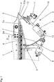
- Fig. 1 are a portion of an Apexzubringers 1, arranged next to the Apexzubringer 1 guide device 2, a cutting device 3 and a material web 4 are shown.
- the material web 4 is produced in particular by extrusion from a rubber mixture and has a cross section which is customary for an apex (core profile).
- the web 4 by means of the Apexzubringers 1 according to the direction indicated by the arrow D transport direction upright, for example, on a bar or the like, transported to a directly adjacent to the Apexzubringer 1 cutting plate 5.
- the material web 4 is cut by means of the cutting device 3.
- the cut-to-length material web pieces formed in the process are subsequently shaped in each case into an annular apex whose end portions are spliced in an overlapping manner.
- the annular apex is joined together with a bead core to form a core package.
- the apex feeder 1 can also be arranged such that the material web 4 is transported in a lying orientation to the cutting device 3. The orientation of the cutting device 3 relative to the Apexzubringer 1 is to be adjusted accordingly.
- the guide device 2 has a concave curved, in particular circular arc curved, guide surface 2a and is pivotally mounted on a non-designated frame or the like via a hinge 6.
- the guide device 2 is by means of a particular pneumatically operated drive 8 together with the cutting device 3 and the hold-7 around the Joint 6 pivotable such that the distance of the cutting device 3 and the pressure element 7a of the cutting plate 5 can be changed and adjusted.
- cutting device 3 pivoted away from the cutting plate 5 the material web 4 to be cut off can be conveyed to the cutting plate 5. If the desired length of material web 4 is conveyed forward, the hold-down device 7 and the cutting device 3 are pivoted back again so that the hold-down device 7 presses the material web 4 against the cutting plate 5.
- the cutting device 3 has a holder 9 with a knife drive 10 and an adjusting unit 11 arranged on the knife drive 10 with a knife 12 directed towards the cutting plate 5.
- the holder 9 is in a manner not shown along the guide surface 2a adjustable and fixed relative to this by means of a clamping device 13, so that the formed between the material web plane and the knife 12 first cutting angle ⁇ is adjustable.
- the guide surface 2a is preferably designed such that the first intersection angle ⁇ can be between 10 ° and 45 °.
- the knife 12 has a cutting edge 12 a, which at the in Fig. 1 is oriented vertically oriented embodiment ( Fig. 3a ).
- the blade 12 can be moved linearly away from the cutting plate 5 while maintaining the cutting angle ⁇ and away from it.
- the knife 12 is moved toward the cutting plate 5, wherein the cutting edge 12a strikes over its entire extent substantially simultaneously on the material web 4, so that it is cut across its entire width in one.
- the material web 4 is therefore along a substantially vertical cutting line, which in Fig. 1 as point P occurs, cut through.
- Fig. 2a shows a section of the material web 4 with a cut surface S 1 created according to this cutting process, whose size (surface area) depends on the set first cutting angle ⁇ . The smaller the first intersection angle ⁇ was chosen, the larger the intersection area S 1 .
- the guide surface 2a is designed in the form of a cylinder shell piece whose cylinder axis lies in the material web plane and is aligned perpendicular to the transport direction D. Since in this embodiment the point P and thus also the cutting line are always at the same position at all cutting angles ⁇ , it is not necessary to have further devices, components, components and the like downstream of the apex feeder 1 and the cutting device 3 for further processing or onward transport the cut material web pieces to adapt to different cutting angle ⁇ .
- the cutting process can be carried out such that substantially parallelogram-shaped cut surfaces S 2 > S 1 (FIG. Fig. 2b ) are formed.
- the knife 12 is to be aligned by means of the setting unit 11 with respect to the vertical direction at a cutting angle ⁇ , the angle of intersection ⁇ being maintained ( Fig. 2b ).
- the blade 12 is inclined by means of the adjusting unit 11 to the desired cutting angle ⁇ .
- the cutting operation is performed. In this embodiment, too, it must be ensured that the width of the blade 12 'is so large that, under the possible cutting angles ⁇ , the material web 4 is cut through its entire width in one.
- the blade of the blade is inclined so that after setting the desired cutting angle ⁇ and when performing a cutting operation at this cutting angle ⁇ , the entire blade simultaneously impinges on the cutting plate 5.
- Fig. 3b shows the view of such a knife 12 'with a blade 12a'.
- the cutting edge 12a ' extends at an angle ⁇ of, for example, 15 ° and lies at an adjusted cutting angle ⁇ in a plane running parallel to the material web plane.
- the punctual position indicated by the point P 2 is constant at all adjustable cutting angles ⁇ .
- the axis of rotation of the Actuator 11 the line of intersection of the horizontally standing on the web level and through the lower edge of the web 4 extending plane and that plane which is spanned by the material web 4 facing surface of the blade 12, 12 '.
Landscapes
- Engineering & Computer Science (AREA)
- Mechanical Engineering (AREA)
- Life Sciences & Earth Sciences (AREA)
- Forests & Forestry (AREA)
- Textile Engineering (AREA)
- Treatment Of Fiber Materials (AREA)
- Tyre Moulding (AREA)
- Nonmetal Cutting Devices (AREA)
Description
Die Erfindung betrifft Vorrichtung zum Ablängen einer Materialbahn aus einer Kautschukmischung mit einem Zubringer zum Transport der Materialbahn zu einer Schneideinrichtung mit einem Messer, dessen Schneide eine Breite aufweist, welche zumindest der Breite der Materialbahn entspricht, wobei die Materialbahn mittels des Messers über ihre gesamte Breite vorzugsweise simultan durchschneidbar ist.The invention relates to a device for cutting a material web from a rubber mixture with a feeder for transporting the material web to a cutting device with a knife whose cutting edge has a width which corresponds at least to the width of the material web, wherein the material web preferably by means of the knife over its entire width is simultaneously cut through.
Eine derartige Vorrichtung ist beispielsweise aus derSuch a device is for example from the
Aus derFrom the
Es ist bekannt und üblich, im Zuge der Reifenfertigung Kernpakete (Fertigkerne) bestehend aus Wulstkern und Apex (Kernprofil) bereitzustellen. Hierzu wird eine aus einer Kautschukmischung hergestellte Materialbahn mittels einer Schneideinrichtung abgelängt, die Materialbahnstücke jeweils zu einem Ring geformt und ihre Endabschnitte überlappend gespleißt. Der derart erstellte ringförmige Apex wird auf einen ringförmigen Wulstkern appliziert. Um ein Lösen des Spleißbereiches nach erfolgter Applikation des Apexes auf dem Wulstkern zu vermeiden, ist es von Vorteil, die Spleißfläche größtmöglich auszuführen.It is known and customary in the course of tire production to provide core packages (finished cores) consisting of bead core and apex (core profile). For this purpose, a material web made of a rubber mixture is cut to length by means of a cutting device, the material web pieces are each formed into a ring and spliced overlapping their end portions. The thus created annular apex is applied to an annular bead core. In order to avoid a loosening of the splice region after the application of the apex to the bead core, it is advantageous to make the splicing surface as large as possible.
Es ist ferner üblich, die Materialbahn unter einem Schnittwinkel von bis zu 45° relativ zur Materialbahnebene zu schneiden, wobei eine im Wesentlichen rechteckige Spleißfläche gebildet wird. Der Schnittwinkel ist bei den aktuell bekannten Anlagen durch die Anordnung der Schneideinrichtung fest vorgegeben. Um die Schnittfläche weiter zu vergrößern, kann die Materialbahn über ihrer Breite unter einem von 90° abweichenden Schnittwinkel geschnitten werden, sodass eine im Wesentlichen parallelogrammförmige Schnittfläche gebildet wird. Dieser Schnittwinkel wird üblicherweise mit zumindest 45° festgelegt. Derzeit sind keine Anlagen bekannt, bei welchen diese Schnittwinkel und beliebig und variabel gewählt werden können. In Abhängigkeit des zu fertigenden Schnittwinkel wie gewünscht variieren zu können, ist es erforderlich, Schneideinrichtungen mit Wechselteilen zu verwenden.It is also customary to cut the material web at an angle of intersection of up to 45 ° relative to the material web plane, wherein a substantially rectangular splicing surface is formed. The cutting angle is fixed in the currently known systems by the arrangement of the cutting device. In order to further increase the sectional area, the material web can be cut over its width at a cutting angle deviating from 90 °, so that a substantially parallelogram-shaped cut surface is formed. This cutting angle is usually set with at least 45 °. Currently, no facilities are known in which these cutting angles and can be chosen arbitrarily and variably. Depending on the one to be produced Cutting angle can be varied as desired, it is necessary to use cutting devices with change parts.
Der Erfindung liegt daher die Aufgabe zugrunde, eine Vorrichtung bereitzustellen, welche auf komfortable Weise das Ablängen einer Materialbahn unter variablen Schnittwinkeln gestattet.The invention is therefore based on the object to provide a device which allows the cutting of a material web under variable cutting angles in a comfortable manner.
Die gestellte Aufgabe wird erfindungsgemäß dadurch gelöst, dass neben dem Zubringer eine Führungseinrichtung angeordnet ist, welche eine konkav gekrümmte Führungsfläche aufweist und entlang welcher eine das Messer tragende Stelleinheit verstell- und fixierbar ist, sodass ein erster spitzer Schnittwinkel relativ zur Materialbahnebene stufenlos einstellbar ist, wobei das Messer mittels der Stelleinheit unter Beibehalten des eingestellten ersten Schnittwinkels kippbar ist, sodass die Materialbahn gleichzeitig unter einem zweiten Schnittwinkel zur Bildung einer parallelogrammförmigen von 90° abweichende Winkel aufweisende Schnittfläche durchschneidbar ist.The stated object is achieved in that next to the feeder, a guide device is arranged, which has a concave curved guide surface and along which a knife bearing adjusting unit is adjustable and fixable, so that a first acute cutting angle is continuously adjustable relative to the web plane, wherein the knife is tiltable by means of the adjusting unit while maintaining the set first cutting angle, so that the material web can be cut through at the same time at a second cutting angle to form a parallelogram-shaped cut surface deviating from 90 °.
Durch das Vorsehen einer das Messer tragenden Stelleinheit mit einer konkav gekrümmten Führungsfläche ist es auf besonders rationelle Weise möglich, den ersten spitzen Schnittwinkel zu variieren und seine Größe einzustellen. Mittels der Stelleinheit ist es ferner möglich, das Messer derart zu kippen, dass der Schneidvorgang gleichzeitig unter einem zweiten einstellbaren Schnittwinkel durchführbar ist, sodass eine parallelogrammförmige Schnittfläche erstellt wird und dementsprechend eine größere Spleißfläche erzielt wird. Mit der erfindungsgemäßen Vorrichtung ist es daher auf besonders komfortable Weise möglich, Materialbahnstücke mit relativ großen Schnittflächen zu erstellen. Da in Abhängigkeit der Materialeigenschaften der zu spleißenden Materialbahnstücke unterschiedliche Schnittwinkel und unterschiedliche Schnittflächen für den nachfolgenden Spleißvorgang vorteilhaft sind, lässt sich mit der erfindungsgemäßen Vorrichtung die Qualität des Spleißes deutlich verbessern.By providing a control unit carrying the blade with a concavely curved guide surface, it is possible in a particularly rational manner to vary the first acute cutting angle and to adjust its size. By means of the adjusting unit, it is also possible to tilt the knife so that the cutting operation is carried out simultaneously at a second adjustable cutting angle, so that a parallelogram-shaped cut surface is created and, accordingly, a larger splice surface is achieved. With the device according to the invention it is therefore possible in a particularly comfortable way to create material web pieces with relatively large cut surfaces. Since, depending on the material properties of the material web pieces to be spliced, different cutting angles and different cutting surfaces are advantageous for the subsequent splicing process, the quality of the splice can be significantly improved with the device according to the invention.
Bei einer bevorzugten erfindungsgemäßen Ausführungsform der Erfindung ist die Führungsfläche in Form eines Zylindermantelstückes ausgeführt, dessen Zylinderachse in der Materialbahnebene liegt und senkrecht zur Transportrichtung der Materialbahn ausgerichtet ist. Da sich bei dieser Ausführungsform die Schnittlinie des Messers an der Materialbahn unabhängig vom ersten Schnittwinkel immer an derselben Position befindet, ist es nicht erforderlich, weitere dem Apexzubringer und der Schneideinrichtung nachgelagerte Vorrichtungen, Komponenten, Bauteile und dergleichen zur Weiterverarbeitung bzw. zum Weitertransport der zugeschnittenen Materialbahnstücke an unterschiedliche erste Schnittwinkel anzupassen.In a preferred embodiment of the invention, the guide surface is designed in the form of a cylinder shell piece whose cylinder axis in the web level lies and is aligned perpendicular to the transport direction of the web. Since, in this embodiment, the cutting line of the knife on the material web is always at the same position independently of the first cutting angle, it is not necessary to have further devices, components, components and the like downstream of the apex feeder and the cutting device for further processing or further transport of the cut material web pieces to adapt to different first cutting angle.
Für eine besonders schnelle und einfache Vorförderung der Materialbahn im gewünschten Ausmaß ist es von Vorteil, wenn die Führungseinrichtung gemeinsam mit der Stelleinheit und dem Messer aus dem Schneidbereich wegbewegbar ist. Ist die gewünschte Länge an Materialbahn vorgefördert, wird die Führungseinrichtung zur Durchführung der Schneidvorgänge wieder zurückbewegt.For a particularly quick and easy advancement of the material web to the desired extent, it is advantageous if the guide device can be moved away from the cutting area together with the setting unit and the knife. If the desired length of material web is conveyed forward, the guide device is moved back to carry out the cutting operations.
Zur Erstellung besonders exakter, qualitativ einwandfreier Schnittflächen ist vorzugsweise ein die Materialbahn vor dem Schneidbereich fixierender Niederhalter mit einem elastisch biegbaren Andrückelement angeordnet.In order to produce particularly precise, qualitatively perfect cut surfaces, a holding-down device which fixes the material web in front of the cutting region is preferably arranged with an elastically bendable pressing element.
Weitere Merkmale, Vorteile und Einzelheiten der Erfindung werden nun anhand der Zeichnung, die schematisch ein Ausführungsbeispiel der Erfindung darstellt, näher beschrieben. Dabei zeigen
-
Fig. 1 eine schematische Ansicht einer Vorrichtung zum Ablängen einer Materialbahn in Draufsicht gemäß einer Ausführungsform der Erfindung, -
Fig. 2a und Fig. 2b je eine mittels der Vorrichtung ausFig. 1 geschnittene Materialbahn und -
Fig. 3a und Fig. 3b unterschiedliche Ausführungsformen eines Messers.
-
Fig. 1 a schematic view of an apparatus for cutting a material web in plan view according to an embodiment of the invention, -
Fig. 2a and Fig. 2b one each by means of the deviceFig. 1 cut material web and -
Fig. 3a and Fig. 3b different embodiments of a knife.
In der nachfolgenden Beschreibung beziehen sich Begriffe wie vertikal, horizontal und dergleichen auf die in den Figuren gezeigte Anordnung der betreffenden Bauteile der Vorrichtung. Unter dem Begriff Materialbahnebene wird im Nachfolgenden jene Ebene verstanden, entlang welcher die Materialbahn einer Schneideinrichtung zugeführt wird.In the following description, terms such as vertical, horizontal and the like refer to the arrangement shown in the figures of the respective components of the Contraption. The term material web level is understood below to mean the plane along which the material web is fed to a cutting device.
In
Die Materialbahn 4 wird insbesondere durch Extrusion aus einer Kautschukmischung hergestellt und weist einen für einen Apex (Kernprofil) üblichen Querschnitt auf. Bei der in
Die Führungseinrichtung 2 weist eine konkav gekrümmte, insbesondere kreisbogenförmig gekrümmte, Führungsfläche 2a auf und ist an einem nicht bezeichneten Gestell oder dergleichen über ein Gelenk 6 schwenkbar angeordnet. An der Führungseinrichtung 2 ist ein zur Schneidplatte 5 gerichteter Niederhalter 7 angeordnet, welcher ein elastisch biegbares Andrückelement 7a aufweist, mittels welchem die abzulängende Materialbahn 4 gegen die Schneidplatte 5 gedrückt wird. Diese Maßnahme unterstützt das Erstellen von besonders exakten, qualitativ einwandfreien Schnittflächen.The
Die Führungseinrichtung 2 ist mittels eines insbesondere pneumatisch betriebenen Antriebes 8 gemeinsam mit der Schneideinrichtung 3 und dem Niederhalter 7 um das Gelenk 6 derart schwenkbar, dass der Abstand der Schneideinrichtung 3 und des Andrückelementes 7a von der Schneidplatte 5 geändert und eingestellt werden kann. Bei von der Schneidplatte 5 weggeschwenkter Schneideinrichtung 3 kann die abzulängende Materialbahn 4 zur Schneidplatte 5 gefördert werden. Ist die gewünschte Länge an Materialbahn 4 vorgefördert, werden der Niederhalter 7 und die Schneideinrichtung 3 wieder zurückgeschwenkt, sodass der Niederhalter 7 die Materialbahn 4 gegen die Schneidplatte 5 drückt.The
Die Schneideinrichtung 3 weist eine Halterung 9 mit einem Messerantrieb 10 sowie eine am Messerantrieb 10 angeordnete Stelleinheit 11 mit einem zur Schneidplatte 5 gerichteten Messer 12 auf. Die Halterung 9 ist auf nicht gezeigte Weise entlang der Führungsfläche 2a verstellbar und gegenüber dieser mittels einer Klemmeinrichtung 13 fixierbar, sodass der zwischen der Materialbahnebene und dem Messer 12 gebildete erste Schnittwinkel α einstellbar ist. Die Führungsfläche 2a ist vorzugsweise derart ausgeführt, dass der erste Schnittwinkel α zwischen 10° und 45° betragen kann.The
Das Messer 12 weist eine Schneide 12a auf, welche bei der in
Bei einer bevorzugten Ausführungsform der Erfindung ist die Führungsfläche 2a in Form eines Zylindermantelstückes ausgeführt, dessen Zylinderachse in der Materialbahnebene liegt und senkrecht zur Transportrichtung D ausgerichtet ist. Da sich bei dieser Ausführungsform der Punkt P und damit auch die Schnittlinie bei sämtlichen Schnittwinkeln α immer an derselben Position befinden, ist es nicht erforderlich, weitere dem Apexzubringer 1 und der Schneideinrichtung 3 nachgelagerte Vorrichtungen, Komponenten, Bauteile und dergleichen zur Weiterverarbeitung bzw. zum Weitertransport der zugeschnittenen Materialbahnstücke an unterschiedliche Schnittwinkel α anzupassen.In a preferred embodiment of the invention, the
Um die Schnittfläche der Materialbahn 4 gegenüber der in
Bei einer besonders bevorzugten Ausführungsform der Erfindung verläuft die Schneide des Messers derart schräg, dass nach Einstellung des gewünschten Schnittwinkels β und bei Durchführung eines Schneidvorganges unter diesem Schnittwinkel β die gesamte Schneide gleichzeitig auf die Schneidplatte 5 auftrifft.
Bei einer besonders bevorzugten Ausführung der Erfindung ist die durch den Punkt P2 gekennzeichnete punktuelle Position bei sämtlichen einstellbaren Schnittwinkeln β konstant. Bei dieser erfindungsgemäßen Ausführungsform ist die Drehachse der Stelleinheit 11 die Schnittgerade der horizontal auf die Materialbahnebene stehenden und durch die Unterkante der Materialbahn 4 verlaufenden Ebene und jener Ebene, welche durch die der Materialbahn 4 zugewandten Fläche des Messers 12, 12' aufgespannt wird.In a particularly preferred embodiment of the invention, the punctual position indicated by the point P 2 is constant at all adjustable cutting angles β. In this embodiment according to the invention, the axis of rotation of the
- 11
- ApexzubringerApexzubringer
- 22
- Führungseinrichtungguide means
- 2a2a
- Führungsflächeguide surface
- 33
- Schneideinrichtungcutter
- 44
- Materialbahnweb
- 55
- Schneidplattecutting board
- 66
- Gelenkjoint
- 77
- NiederhalterStripper plate
- 7a7a
- Andrückelementpressing element
- 88th
- Antriebdrive
- 99
- Halterungselementsupporting member
- 1010
- Messerantriebknife drive
- 1111
- Stelleinheitactuator
- 1212
- Messerknife
- 12'12 '
- Messerknife
- 12a12a
- Schneidecutting edge
- 12a'12a '
- Schneidecutting edge
- 1313
- Klemmeinrichtungclamper
Claims (5)
- Apparatus for cutting to length a material web (4) made of a rubber compound, having a conveyor (1) for transporting the material web (4) to a cutting device (3) with a cutter (12, 12'), the blade (12a, 12a') of which has a width that corresponds at least to the width of the material web (4), wherein the material web (4) is able to be severed preferably simultaneously across its entire width by means of the cutter (12, 12'),
characterized
in that, next to the conveyor (1), a guide device (2) is arranged, which has a concavely curved guide surface (2a) and along which an adjusting unit (11) carrying the cutter (12, 12') is able to be adjusted and fixed, such that a first acute cutting angle (α) relative to the material web plane is continuously adjustable, wherein the cutter (12, 12') is tiltable by means of the adjusting unit (11) with the set first cutting angle (α) being maintained, such that the material web (4) is able to be severed simultaneously at a second cutting angle (β) to form a parallelogram-shaped cut surface (S2) having angles other than 90°. - Apparatus according to Claim 1,
characterized in that
the cutter (12, 12') is arranged on the adjusting unit (11) in such a way,
wherein the "point-wise" position (P2) of the cut material web (4) is independent of the set second cutting angle (β). - Apparatus according to Claim 1 or 2, characterized in that the guide surface (2a) is embodied in the form of a cylinder jacket section, the cylinder axis of which lies in the material web plane and is oriented perpendicularly to the transport direction (D) of the material web (4).
- Apparatus according to one of Claims 1 to 3,
characterized in that the guide device (2) is movable away from the cutting region together with the adjusting unit (11) and the cutter (12, 12'). - Apparatus according to one of Claims 1 to 4,
characterized in that a holding-down means (7) that fixes the material web (4) in front of the cutting region and has an elastically bendable contact-pressure element (7a) is arranged on the guide device (2).
Applications Claiming Priority (1)
| Application Number | Priority Date | Filing Date | Title |
|---|---|---|---|
| DE102015209873.7A DE102015209873A1 (en) | 2015-05-29 | 2015-05-29 | Device for cutting a material web |
Publications (2)
| Publication Number | Publication Date |
|---|---|
| EP3098036A1 EP3098036A1 (en) | 2016-11-30 |
| EP3098036B1 true EP3098036B1 (en) | 2019-10-02 |
Family
ID=55443058
Family Applications (1)
| Application Number | Title | Priority Date | Filing Date |
|---|---|---|---|
| EP16154773.2A Active EP3098036B1 (en) | 2015-05-29 | 2016-02-09 | Device for cutting a sheet of material |
Country Status (2)
| Country | Link |
|---|---|
| EP (1) | EP3098036B1 (en) |
| DE (1) | DE102015209873A1 (en) |
Family Cites Families (6)
| Publication number | Priority date | Publication date | Assignee | Title |
|---|---|---|---|---|
| GB995132A (en) * | 1961-05-02 | 1965-06-16 | Dunlop Rubber Co | Improvements in apparatus for cutting tread strips for pneumatic tyres |
| US6755105B2 (en) * | 2001-06-01 | 2004-06-29 | The Goodyear Tire & Rubber Company | Method and apparatus for cutting elastomeric materials and the article made by the method |
| JP2004202960A (en) * | 2002-12-26 | 2004-07-22 | Sumitomo Rubber Ind Ltd | Jointing device and jointing method for bead apex |
| US7455002B2 (en) * | 2004-12-23 | 2008-11-25 | The Goodyear Tire & Rubber Company | Method for cutting elastomeric materials and the article made by the method |
| US7811399B2 (en) * | 2006-09-21 | 2010-10-12 | The Goodyear Tire & Rubber Company | Tire component cutter apparatus and method of cutting |
| US8245615B2 (en) * | 2008-10-22 | 2012-08-21 | Paul Brazier | Tire tread skiving machine |
-
2015
- 2015-05-29 DE DE102015209873.7A patent/DE102015209873A1/en not_active Withdrawn
-
2016
- 2016-02-09 EP EP16154773.2A patent/EP3098036B1/en active Active
Non-Patent Citations (1)
| Title |
|---|
| None * |
Also Published As
| Publication number | Publication date |
|---|---|
| EP3098036A1 (en) | 2016-11-30 |
| DE102015209873A1 (en) | 2016-12-01 |
Similar Documents
| Publication | Publication Date | Title |
|---|---|---|
| DE102007006754A1 (en) | Veneer cutter | |
| AT514821B1 (en) | Bending press and bending process | |
| EP3125696B1 (en) | Device and method for removing a surface layer including the skin from fish fillets | |
| EP0739692B1 (en) | Cutting device for food products | |
| DE69924565T2 (en) | Method and device for sharpening plate-shaped material | |
| DE102010053199A1 (en) | Device useful for processing continuous material web, preferably planar continuous material, comprises working table as support for the material web, and cutting device for separating the material web at cutting position | |
| DE3920825C2 (en) | Device for trimming and butt welding strip or sheet edges with a laser device | |
| DE3925472A1 (en) | METHOD AND DEVICE FOR CUTTING SANDWICH PANELS | |
| EP3098036B1 (en) | Device for cutting a sheet of material | |
| EP2759215A1 (en) | Device and method for cutting tobacco from a tobacco cake | |
| EP2582479B1 (en) | Method and device for trimming heavy plates | |
| EP2404691B1 (en) | Rotating ring used for machining profiles | |
| DE2062517A1 (en) | Wire cutting device | |
| DE10334739B3 (en) | Holder for use when welding two sections of continuous strip material comprises support plates on either side of central welding unit which swivel upwards about central pivot, so that strips are held at angle to each other | |
| DE202019104780U1 (en) | cutter | |
| EP0145049B1 (en) | Cable-stripping device, especially for conductors with with tough insulation material | |
| EP3684569B1 (en) | Method for segmenting a preferably flat workpiece | |
| WO2017076527A1 (en) | Cutting device for cutting at least one edge of a conveyor belt | |
| DE10322302B4 (en) | Plant for the production of blanks of strip-shaped material | |
| AT405801B (en) | DEVICE AND METHOD FOR CUTTING PLATE-SHAPED STRANDS | |
| EP3081355B1 (en) | Cutting device | |
| DE102019102404A1 (en) | Device and method for cutting a hose provided with a reinforcing element | |
| DE102022130333B3 (en) | Device and method for cutting a strip of deformable material | |
| AT515653B1 (en) | Positioning system of workpieces to be machined and a machine equipped with such a system | |
| DE19929927A1 (en) | Device for separating and transferring an insertion strip |
Legal Events
| Date | Code | Title | Description |
|---|---|---|---|
| PUAI | Public reference made under article 153(3) epc to a published international application that has entered the european phase |
Free format text: ORIGINAL CODE: 0009012 |
|
| AK | Designated contracting states |
Kind code of ref document: A1 Designated state(s): AL AT BE BG CH CY CZ DE DK EE ES FI FR GB GR HR HU IE IS IT LI LT LU LV MC MK MT NL NO PL PT RO RS SE SI SK SM TR |
|
| AX | Request for extension of the european patent |
Extension state: BA ME |
|
| STAA | Information on the status of an ep patent application or granted ep patent |
Free format text: STATUS: REQUEST FOR EXAMINATION WAS MADE |
|
| 17P | Request for examination filed |
Effective date: 20170530 |
|
| RBV | Designated contracting states (corrected) |
Designated state(s): AL AT BE BG CH CY CZ DE DK EE ES FI FR GB GR HR HU IE IS IT LI LT LU LV MC MK MT NL NO PL PT RO RS SE SI SK SM TR |
|
| GRAP | Despatch of communication of intention to grant a patent |
Free format text: ORIGINAL CODE: EPIDOSNIGR1 |
|
| STAA | Information on the status of an ep patent application or granted ep patent |
Free format text: STATUS: GRANT OF PATENT IS INTENDED |
|
| INTG | Intention to grant announced |
Effective date: 20190617 |
|
| GRAS | Grant fee paid |
Free format text: ORIGINAL CODE: EPIDOSNIGR3 |
|
| GRAA | (expected) grant |
Free format text: ORIGINAL CODE: 0009210 |
|
| STAA | Information on the status of an ep patent application or granted ep patent |
Free format text: STATUS: THE PATENT HAS BEEN GRANTED |
|
| AK | Designated contracting states |
Kind code of ref document: B1 Designated state(s): AL AT BE BG CH CY CZ DE DK EE ES FI FR GB GR HR HU IE IS IT LI LT LU LV MC MK MT NL NO PL PT RO RS SE SI SK SM TR |
|
| REG | Reference to a national code |
Ref country code: GB Ref legal event code: FG4D Free format text: NOT ENGLISH |
|
| REG | Reference to a national code |
Ref country code: CH Ref legal event code: EP Ref country code: AT Ref legal event code: REF Ref document number: 1185687 Country of ref document: AT Kind code of ref document: T Effective date: 20191015 |
|
| REG | Reference to a national code |
Ref country code: DE Ref legal event code: R096 Ref document number: 502016006853 Country of ref document: DE |
|
| REG | Reference to a national code |
Ref country code: IE Ref legal event code: FG4D Free format text: LANGUAGE OF EP DOCUMENT: GERMAN |
|
| REG | Reference to a national code |
Ref country code: NL Ref legal event code: FP |
|
| REG | Reference to a national code |
Ref country code: LT Ref legal event code: MG4D |
|
| PG25 | Lapsed in a contracting state [announced via postgrant information from national office to epo] |
Ref country code: LT Free format text: LAPSE BECAUSE OF FAILURE TO SUBMIT A TRANSLATION OF THE DESCRIPTION OR TO PAY THE FEE WITHIN THE PRESCRIBED TIME-LIMIT Effective date: 20191002 Ref country code: NO Free format text: LAPSE BECAUSE OF FAILURE TO SUBMIT A TRANSLATION OF THE DESCRIPTION OR TO PAY THE FEE WITHIN THE PRESCRIBED TIME-LIMIT Effective date: 20200102 Ref country code: GR Free format text: LAPSE BECAUSE OF FAILURE TO SUBMIT A TRANSLATION OF THE DESCRIPTION OR TO PAY THE FEE WITHIN THE PRESCRIBED TIME-LIMIT Effective date: 20200103 Ref country code: PL Free format text: LAPSE BECAUSE OF FAILURE TO SUBMIT A TRANSLATION OF THE DESCRIPTION OR TO PAY THE FEE WITHIN THE PRESCRIBED TIME-LIMIT Effective date: 20191002 Ref country code: ES Free format text: LAPSE BECAUSE OF FAILURE TO SUBMIT A TRANSLATION OF THE DESCRIPTION OR TO PAY THE FEE WITHIN THE PRESCRIBED TIME-LIMIT Effective date: 20191002 Ref country code: FI Free format text: LAPSE BECAUSE OF FAILURE TO SUBMIT A TRANSLATION OF THE DESCRIPTION OR TO PAY THE FEE WITHIN THE PRESCRIBED TIME-LIMIT Effective date: 20191002 Ref country code: BG Free format text: LAPSE BECAUSE OF FAILURE TO SUBMIT A TRANSLATION OF THE DESCRIPTION OR TO PAY THE FEE WITHIN THE PRESCRIBED TIME-LIMIT Effective date: 20200102 Ref country code: LV Free format text: LAPSE BECAUSE OF FAILURE TO SUBMIT A TRANSLATION OF THE DESCRIPTION OR TO PAY THE FEE WITHIN THE PRESCRIBED TIME-LIMIT Effective date: 20191002 Ref country code: PT Free format text: LAPSE BECAUSE OF FAILURE TO SUBMIT A TRANSLATION OF THE DESCRIPTION OR TO PAY THE FEE WITHIN THE PRESCRIBED TIME-LIMIT Effective date: 20200203 Ref country code: SE Free format text: LAPSE BECAUSE OF FAILURE TO SUBMIT A TRANSLATION OF THE DESCRIPTION OR TO PAY THE FEE WITHIN THE PRESCRIBED TIME-LIMIT Effective date: 20191002 |
|
| PG25 | Lapsed in a contracting state [announced via postgrant information from national office to epo] |
Ref country code: HR Free format text: LAPSE BECAUSE OF FAILURE TO SUBMIT A TRANSLATION OF THE DESCRIPTION OR TO PAY THE FEE WITHIN THE PRESCRIBED TIME-LIMIT Effective date: 20191002 Ref country code: IS Free format text: LAPSE BECAUSE OF FAILURE TO SUBMIT A TRANSLATION OF THE DESCRIPTION OR TO PAY THE FEE WITHIN THE PRESCRIBED TIME-LIMIT Effective date: 20200224 Ref country code: RS Free format text: LAPSE BECAUSE OF FAILURE TO SUBMIT A TRANSLATION OF THE DESCRIPTION OR TO PAY THE FEE WITHIN THE PRESCRIBED TIME-LIMIT Effective date: 20191002 Ref country code: CZ Free format text: LAPSE BECAUSE OF FAILURE TO SUBMIT A TRANSLATION OF THE DESCRIPTION OR TO PAY THE FEE WITHIN THE PRESCRIBED TIME-LIMIT Effective date: 20191002 |
|
| PG25 | Lapsed in a contracting state [announced via postgrant information from national office to epo] |
Ref country code: AL Free format text: LAPSE BECAUSE OF FAILURE TO SUBMIT A TRANSLATION OF THE DESCRIPTION OR TO PAY THE FEE WITHIN THE PRESCRIBED TIME-LIMIT Effective date: 20191002 |
|
| REG | Reference to a national code |
Ref country code: DE Ref legal event code: R097 Ref document number: 502016006853 Country of ref document: DE |
|
| PG2D | Information on lapse in contracting state deleted |
Ref country code: IS |
|
| PG25 | Lapsed in a contracting state [announced via postgrant information from national office to epo] |
Ref country code: EE Free format text: LAPSE BECAUSE OF FAILURE TO SUBMIT A TRANSLATION OF THE DESCRIPTION OR TO PAY THE FEE WITHIN THE PRESCRIBED TIME-LIMIT Effective date: 20191002 Ref country code: DK Free format text: LAPSE BECAUSE OF FAILURE TO SUBMIT A TRANSLATION OF THE DESCRIPTION OR TO PAY THE FEE WITHIN THE PRESCRIBED TIME-LIMIT Effective date: 20191002 Ref country code: RO Free format text: LAPSE BECAUSE OF FAILURE TO SUBMIT A TRANSLATION OF THE DESCRIPTION OR TO PAY THE FEE WITHIN THE PRESCRIBED TIME-LIMIT Effective date: 20191002 Ref country code: IS Free format text: LAPSE BECAUSE OF FAILURE TO SUBMIT A TRANSLATION OF THE DESCRIPTION OR TO PAY THE FEE WITHIN THE PRESCRIBED TIME-LIMIT Effective date: 20200202 |
|
| PLBE | No opposition filed within time limit |
Free format text: ORIGINAL CODE: 0009261 |
|
| STAA | Information on the status of an ep patent application or granted ep patent |
Free format text: STATUS: NO OPPOSITION FILED WITHIN TIME LIMIT |
|
| PG25 | Lapsed in a contracting state [announced via postgrant information from national office to epo] |
Ref country code: IT Free format text: LAPSE BECAUSE OF FAILURE TO SUBMIT A TRANSLATION OF THE DESCRIPTION OR TO PAY THE FEE WITHIN THE PRESCRIBED TIME-LIMIT Effective date: 20191002 Ref country code: SK Free format text: LAPSE BECAUSE OF FAILURE TO SUBMIT A TRANSLATION OF THE DESCRIPTION OR TO PAY THE FEE WITHIN THE PRESCRIBED TIME-LIMIT Effective date: 20191002 Ref country code: SM Free format text: LAPSE BECAUSE OF FAILURE TO SUBMIT A TRANSLATION OF THE DESCRIPTION OR TO PAY THE FEE WITHIN THE PRESCRIBED TIME-LIMIT Effective date: 20191002 |
|
| 26N | No opposition filed |
Effective date: 20200703 |
|
| REG | Reference to a national code |
Ref country code: CH Ref legal event code: PL |
|
| GBPC | Gb: european patent ceased through non-payment of renewal fee |
Effective date: 20200209 |
|
| REG | Reference to a national code |
Ref country code: BE Ref legal event code: MM Effective date: 20200229 |
|
| PG25 | Lapsed in a contracting state [announced via postgrant information from national office to epo] |
Ref country code: MC Free format text: LAPSE BECAUSE OF FAILURE TO SUBMIT A TRANSLATION OF THE DESCRIPTION OR TO PAY THE FEE WITHIN THE PRESCRIBED TIME-LIMIT Effective date: 20191002 Ref country code: LU Free format text: LAPSE BECAUSE OF NON-PAYMENT OF DUE FEES Effective date: 20200209 |
|
| PG25 | Lapsed in a contracting state [announced via postgrant information from national office to epo] |
Ref country code: CH Free format text: LAPSE BECAUSE OF NON-PAYMENT OF DUE FEES Effective date: 20200229 Ref country code: SI Free format text: LAPSE BECAUSE OF FAILURE TO SUBMIT A TRANSLATION OF THE DESCRIPTION OR TO PAY THE FEE WITHIN THE PRESCRIBED TIME-LIMIT Effective date: 20191002 Ref country code: LI Free format text: LAPSE BECAUSE OF NON-PAYMENT OF DUE FEES Effective date: 20200229 |
|
| PG25 | Lapsed in a contracting state [announced via postgrant information from national office to epo] |
Ref country code: GB Free format text: LAPSE BECAUSE OF NON-PAYMENT OF DUE FEES Effective date: 20200209 Ref country code: IE Free format text: LAPSE BECAUSE OF NON-PAYMENT OF DUE FEES Effective date: 20200209 |
|
| PG25 | Lapsed in a contracting state [announced via postgrant information from national office to epo] |
Ref country code: BE Free format text: LAPSE BECAUSE OF NON-PAYMENT OF DUE FEES Effective date: 20200229 |
|
| REG | Reference to a national code |
Ref country code: AT Ref legal event code: MM01 Ref document number: 1185687 Country of ref document: AT Kind code of ref document: T Effective date: 20210209 |
|
| PG25 | Lapsed in a contracting state [announced via postgrant information from national office to epo] |
Ref country code: AT Free format text: LAPSE BECAUSE OF NON-PAYMENT OF DUE FEES Effective date: 20210209 |
|
| PG25 | Lapsed in a contracting state [announced via postgrant information from national office to epo] |
Ref country code: TR Free format text: LAPSE BECAUSE OF FAILURE TO SUBMIT A TRANSLATION OF THE DESCRIPTION OR TO PAY THE FEE WITHIN THE PRESCRIBED TIME-LIMIT Effective date: 20191002 Ref country code: MT Free format text: LAPSE BECAUSE OF FAILURE TO SUBMIT A TRANSLATION OF THE DESCRIPTION OR TO PAY THE FEE WITHIN THE PRESCRIBED TIME-LIMIT Effective date: 20191002 Ref country code: CY Free format text: LAPSE BECAUSE OF FAILURE TO SUBMIT A TRANSLATION OF THE DESCRIPTION OR TO PAY THE FEE WITHIN THE PRESCRIBED TIME-LIMIT Effective date: 20191002 |
|
| PG25 | Lapsed in a contracting state [announced via postgrant information from national office to epo] |
Ref country code: MK Free format text: LAPSE BECAUSE OF FAILURE TO SUBMIT A TRANSLATION OF THE DESCRIPTION OR TO PAY THE FEE WITHIN THE PRESCRIBED TIME-LIMIT Effective date: 20191002 |
|
| REG | Reference to a national code |
Ref country code: DE Ref legal event code: R081 Ref document number: 502016006853 Country of ref document: DE Owner name: CONTINENTAL REIFEN DEUTSCHLAND GMBH, DE Free format text: FORMER OWNER: CONTINENTAL REIFEN DEUTSCHLAND GMBH, 30165 HANNOVER, DE |
|
| PGFP | Annual fee paid to national office [announced via postgrant information from national office to epo] |
Ref country code: NL Payment date: 20240219 Year of fee payment: 9 |
|
| PGFP | Annual fee paid to national office [announced via postgrant information from national office to epo] |
Ref country code: DE Payment date: 20240229 Year of fee payment: 9 |
|
| PGFP | Annual fee paid to national office [announced via postgrant information from national office to epo] |
Ref country code: FR Payment date: 20240221 Year of fee payment: 9 |