EP3097880A1 - Therapeutic apparatus - Google Patents
Therapeutic apparatus Download PDFInfo
- Publication number
- EP3097880A1 EP3097880A1 EP15740270.2A EP15740270A EP3097880A1 EP 3097880 A1 EP3097880 A1 EP 3097880A1 EP 15740270 A EP15740270 A EP 15740270A EP 3097880 A1 EP3097880 A1 EP 3097880A1
- Authority
- EP
- European Patent Office
- Prior art keywords
- high frequency
- frequency electrode
- electric resistance
- region
- resistance pattern
- Prior art date
- Legal status (The legal status is an assumption and is not a legal conclusion. Google has not performed a legal analysis and makes no representation as to the accuracy of the status listed.)
- Withdrawn
Links
- 230000001225 therapeutic effect Effects 0.000 title 1
- 238000006243 chemical reaction Methods 0.000 claims abstract description 62
- 238000011282 treatment Methods 0.000 claims abstract description 31
- 230000020169 heat generation Effects 0.000 claims description 37
- WABPQHHGFIMREM-UHFFFAOYSA-N lead(0) Chemical compound [Pb] WABPQHHGFIMREM-UHFFFAOYSA-N 0.000 claims description 6
- 210000001519 tissue Anatomy 0.000 description 32
- 230000001070 adhesive effect Effects 0.000 description 24
- 239000000853 adhesive Substances 0.000 description 22
- 238000010336 energy treatment Methods 0.000 description 11
- 239000000758 substrate Substances 0.000 description 9
- 238000010586 diagram Methods 0.000 description 3
- 238000010438 heat treatment Methods 0.000 description 3
- 238000009413 insulation Methods 0.000 description 2
- RYGMFSIKBFXOCR-UHFFFAOYSA-N Copper Chemical compound [Cu] RYGMFSIKBFXOCR-UHFFFAOYSA-N 0.000 description 1
- 239000004642 Polyimide Substances 0.000 description 1
- 210000000683 abdominal cavity Anatomy 0.000 description 1
- 210000003815 abdominal wall Anatomy 0.000 description 1
- PNEYBMLMFCGWSK-UHFFFAOYSA-N aluminium oxide Inorganic materials [O-2].[O-2].[O-2].[Al+3].[Al+3] PNEYBMLMFCGWSK-UHFFFAOYSA-N 0.000 description 1
- 230000015572 biosynthetic process Effects 0.000 description 1
- 239000000919 ceramic Substances 0.000 description 1
- 230000015271 coagulation Effects 0.000 description 1
- 238000005345 coagulation Methods 0.000 description 1
- 229910052802 copper Inorganic materials 0.000 description 1
- 239000010949 copper Substances 0.000 description 1
- PMHQVHHXPFUNSP-UHFFFAOYSA-M copper(1+);methylsulfanylmethane;bromide Chemical compound Br[Cu].CSC PMHQVHHXPFUNSP-UHFFFAOYSA-M 0.000 description 1
- 230000003247 decreasing effect Effects 0.000 description 1
- 239000003822 epoxy resin Substances 0.000 description 1
- 229920006015 heat resistant resin Polymers 0.000 description 1
- 238000000034 method Methods 0.000 description 1
- 230000000149 penetrating effect Effects 0.000 description 1
- 210000004303 peritoneum Anatomy 0.000 description 1
- 229920000647 polyepoxide Polymers 0.000 description 1
- 229920001721 polyimide Polymers 0.000 description 1
- 238000005476 soldering Methods 0.000 description 1
- 238000001356 surgical procedure Methods 0.000 description 1
Images




Classifications
-
- A—HUMAN NECESSITIES
- A61—MEDICAL OR VETERINARY SCIENCE; HYGIENE
- A61B—DIAGNOSIS; SURGERY; IDENTIFICATION
- A61B18/00—Surgical instruments, devices or methods for transferring non-mechanical forms of energy to or from the body
- A61B18/04—Surgical instruments, devices or methods for transferring non-mechanical forms of energy to or from the body by heating
- A61B18/08—Surgical instruments, devices or methods for transferring non-mechanical forms of energy to or from the body by heating by means of electrically-heated probes
- A61B18/082—Probes or electrodes therefor
- A61B18/085—Forceps, scissors
-
- A—HUMAN NECESSITIES
- A61—MEDICAL OR VETERINARY SCIENCE; HYGIENE
- A61B—DIAGNOSIS; SURGERY; IDENTIFICATION
- A61B18/00—Surgical instruments, devices or methods for transferring non-mechanical forms of energy to or from the body
- A61B18/04—Surgical instruments, devices or methods for transferring non-mechanical forms of energy to or from the body by heating
- A61B18/12—Surgical instruments, devices or methods for transferring non-mechanical forms of energy to or from the body by heating by passing a current through the tissue to be heated, e.g. high-frequency current
- A61B18/14—Probes or electrodes therefor
- A61B18/1442—Probes having pivoting end effectors, e.g. forceps
- A61B18/1445—Probes having pivoting end effectors, e.g. forceps at the distal end of a shaft, e.g. forceps or scissors at the end of a rigid rod
-
- A—HUMAN NECESSITIES
- A61—MEDICAL OR VETERINARY SCIENCE; HYGIENE
- A61B—DIAGNOSIS; SURGERY; IDENTIFICATION
- A61B18/00—Surgical instruments, devices or methods for transferring non-mechanical forms of energy to or from the body
- A61B2018/00053—Mechanical features of the instrument of device
- A61B2018/00059—Material properties
- A61B2018/00089—Thermal conductivity
- A61B2018/00095—Thermal conductivity high, i.e. heat conducting
-
- A—HUMAN NECESSITIES
- A61—MEDICAL OR VETERINARY SCIENCE; HYGIENE
- A61B—DIAGNOSIS; SURGERY; IDENTIFICATION
- A61B18/00—Surgical instruments, devices or methods for transferring non-mechanical forms of energy to or from the body
- A61B2018/00053—Mechanical features of the instrument of device
- A61B2018/00184—Moving parts
- A61B2018/00196—Moving parts reciprocating lengthwise
-
- A—HUMAN NECESSITIES
- A61—MEDICAL OR VETERINARY SCIENCE; HYGIENE
- A61B—DIAGNOSIS; SURGERY; IDENTIFICATION
- A61B18/00—Surgical instruments, devices or methods for transferring non-mechanical forms of energy to or from the body
- A61B2018/00571—Surgical instruments, devices or methods for transferring non-mechanical forms of energy to or from the body for achieving a particular surgical effect
- A61B2018/00577—Ablation
-
- A—HUMAN NECESSITIES
- A61—MEDICAL OR VETERINARY SCIENCE; HYGIENE
- A61B—DIAGNOSIS; SURGERY; IDENTIFICATION
- A61B18/00—Surgical instruments, devices or methods for transferring non-mechanical forms of energy to or from the body
- A61B2018/00571—Surgical instruments, devices or methods for transferring non-mechanical forms of energy to or from the body for achieving a particular surgical effect
- A61B2018/00589—Coagulation
-
- A—HUMAN NECESSITIES
- A61—MEDICAL OR VETERINARY SCIENCE; HYGIENE
- A61B—DIAGNOSIS; SURGERY; IDENTIFICATION
- A61B18/00—Surgical instruments, devices or methods for transferring non-mechanical forms of energy to or from the body
- A61B2018/00571—Surgical instruments, devices or methods for transferring non-mechanical forms of energy to or from the body for achieving a particular surgical effect
- A61B2018/00595—Cauterization
-
- A—HUMAN NECESSITIES
- A61—MEDICAL OR VETERINARY SCIENCE; HYGIENE
- A61B—DIAGNOSIS; SURGERY; IDENTIFICATION
- A61B18/00—Surgical instruments, devices or methods for transferring non-mechanical forms of energy to or from the body
- A61B2018/00571—Surgical instruments, devices or methods for transferring non-mechanical forms of energy to or from the body for achieving a particular surgical effect
- A61B2018/00607—Coagulation and cutting with the same instrument
-
- A—HUMAN NECESSITIES
- A61—MEDICAL OR VETERINARY SCIENCE; HYGIENE
- A61B—DIAGNOSIS; SURGERY; IDENTIFICATION
- A61B18/00—Surgical instruments, devices or methods for transferring non-mechanical forms of energy to or from the body
- A61B2018/00994—Surgical instruments, devices or methods for transferring non-mechanical forms of energy to or from the body combining two or more different kinds of non-mechanical energy or combining one or more non-mechanical energies with ultrasound
-
- A—HUMAN NECESSITIES
- A61—MEDICAL OR VETERINARY SCIENCE; HYGIENE
- A61B—DIAGNOSIS; SURGERY; IDENTIFICATION
- A61B18/00—Surgical instruments, devices or methods for transferring non-mechanical forms of energy to or from the body
- A61B18/04—Surgical instruments, devices or methods for transferring non-mechanical forms of energy to or from the body by heating
- A61B18/12—Surgical instruments, devices or methods for transferring non-mechanical forms of energy to or from the body by heating by passing a current through the tissue to be heated, e.g. high-frequency current
- A61B18/1206—Generators therefor
- A61B2018/1266—Generators therefor with DC current output
-
- A—HUMAN NECESSITIES
- A61—MEDICAL OR VETERINARY SCIENCE; HYGIENE
- A61B—DIAGNOSIS; SURGERY; IDENTIFICATION
- A61B18/00—Surgical instruments, devices or methods for transferring non-mechanical forms of energy to or from the body
- A61B18/04—Surgical instruments, devices or methods for transferring non-mechanical forms of energy to or from the body by heating
- A61B18/12—Surgical instruments, devices or methods for transferring non-mechanical forms of energy to or from the body by heating by passing a current through the tissue to be heated, e.g. high-frequency current
- A61B18/14—Probes or electrodes therefor
- A61B18/1442—Probes having pivoting end effectors, e.g. forceps
- A61B2018/1452—Probes having pivoting end effectors, e.g. forceps including means for cutting
- A61B2018/1455—Probes having pivoting end effectors, e.g. forceps including means for cutting having a moving blade for cutting tissue grasped by the jaws
Definitions
- the present invention relates to a treatment apparatus.
- Jpn. Pat. Appln. KOKAI Publication No. 2013-034568 discloses therein a treatment apparatus described later. More specifically, the treatment apparatus has an openable and closable high frequency electrode which grips a body tissue to be treated. A high frequency electrode current line for applying a high frequency voltage is connected to the high frequency electrode. In addition, the high frequency electrode also functions as a heat transfer plate which conducts heat to the gripped body tissue. The high frequency electrode has a sheet heater arranged as an electrothermal conversion element for heating the high frequency electrode. Accordingly, the treatment apparatus can apply a high frequency voltage to the gripped body tissue, and apply thermal energy on the body tissue. The treatment apparatus can cauterize and treat the body tissue with high frequency energy and thermal energy.
- the high frequency electrode current line is joined directly with the high frequency electrode, and excellent in thermal conductivity. For this reason, heat release from the high frequency electrode current line is significant in the case of the high frequency electrode which functions as a heat transfer plate. Consequently, the temperature of the high frequency electrode is likely to be non-uniform in the region with the high frequency electrode current line connected. However, the temperature of the high frequency electrode is preferably uniform.
- the heat generation density of the electrothermal conversion element is adjusted for each region, and a treatment apparatus is thus provided which has a smaller temperature difference in a heat transfer plate.
- a treatment apparatus according to the present exemplary embodiment is used for treating body tissues.
- the treatment apparatus applies at least one of high frequency energy and thermal energy on body tissues.
- a treatment apparatus 300 is schematically illustrated in FIG. 1 .
- the treatment apparatus 300 comprises an energy treatment tool 310, a control device 370, and a foot switch 380.
- the energy treatment tool 310 is a linear type surgical treatment tool penetrating through the abdominal wall for treatment, for example.
- the energy treatment tool 310 includes a handle 350, a shaft 340 attached on the handle 350, and a holding part 320 provided on the tip end of the shaft 340.
- the holding part 320 is a treatment part which is openable and/or closable and is directed to perform treatments such as coagulation and incision of a body tissue by gripping the body tissue to be treated.
- the side of the holding part 320 will be called tip end side and the side of the handle 350 will be called base end side.
- the handle 350 comprises a plurality of operation knobs 352 for operating the holding part 320.
- a shape of the energy treatment tool 310 illustrated herein is exemplary, and any other shape having the same function may be employed.
- the holding part, the handle, and the operation knobs may have different shapes from the shapes shown in FIG. 1 , and the shaft may be curved.
- the energy treatment tool 310 is not limited to a forceps-like shape for gripping body tissues, but may be a trowel-type treatment tool which is pressed against body tissues in use.
- the handle 350 is connected to the control device 370 via a cable 360.
- the cable 360 and the control device 370 are connected with each other via a connector 365, and the connection is removable to permit replacement of the energy treatment tool 310 in accordance with a treatment to be performed.
- the control device 370 is connected with the foot switch 380.
- the foot-operated foot switch 380 may be replaced with a hand-operated switch or another switch. An operator operates the pedal of the foot switch 380 thereby to switch ON/OFF energy supply from the control device 370 to the energy treatment tool 310.
- FIG. 2A illustrates a state in which the holding part 320 is closed
- FIG. 2B illustrates a state in which the holding part 320 is opened.
- the shaft 340 comprises a tube 342 and a sheath 343.
- the tube 342 is fixed at its base end to the handle 350.
- the sheath 343 is slidably arranged on the outer periphery of the tube 342 in the axial direction of the tube 342.
- the holding part 320 is arranged on the tip end of the tube 342.
- the holding part 320 comprises a first holding member 322 and a second holding member 324.
- the base of the first holding member 322 is fixed on the tip end of the tube 342 in the shaft 340.
- the base of the second holding member 324 is rotatably supported on the tip end of the tube 342 in the shaft 340 by a support pin 346. Therefore, the second holding member 324 axially rotates about the support pin 346 and opens/closes relative to the first holding member 322.
- a cross-section shape in which the base of the first holding member 322 and the base of the second holding member 324 are put together is circular.
- the second holding member 324 is energized by an elastic member 347 such as plate spring to open relative to the first holding member 322.
- an elastic member 347 such as plate spring to open relative to the first holding member 322.
- the tube 342 is provided therein with a first high frequency electrode current line 162 connected to a first high frequency electrode 110 and a second high frequency electrode current line 262 connected to a second high frequency electrode 210, which will be described later.
- the tube 342 is provided therein with a pair of first heater current lines 164 connected to an electrothermal conversion element 140 to function as a heat generation member, which is arranged on the first high frequency electrode 110, and a pair of second heater current lines 264 connected to an electrothermal conversion element arranged on a second high frequency electrode 210.
- a drive rod 344 connected on its base end to one of the operation knobs 352 is movably arranged in the axial direction of the tube 342 inside the tube 342.
- a thin plate-shaped cutter 345 forming a blade on its tip end is arranged on the tip end of the drive rod 344.
- FIG. 3A is a plan view of the first holding member 322 as viewed from a direction of the first high frequency electrode 110.
- FIG. 3B is a cross-section view along the line 3B-3B of FIG. 3A .
- FIG. 3C is a cross-section view along the line 3C-3C of FIG. 3A .
- the first holding member 322 is formed with the first cutter guide groove 332 for guiding the cutter 345.
- the first holding member 322 is provided with the first high frequency electrode 110 including a conductive copper thin plate, for example.
- the first high frequency electrode 110 is configured to contact with a body tissue on either main surface thereof (which will be called first main surface below).
- the first high frequency electrode 110 includes the first cutter guide groove 332, and thus its planar shape is U-shaped as illustrated in FIG. 3A .
- the first high frequency electrode 110 is electrically connected with the first high frequency electrode current line 162 to function as a lead wire for applying a high frequency voltage to the first high frequency electrode 110 in a way described later in detail.
- the first high frequency electrode 110 is connected to the control device 370 via the first high frequency electrode current line 162 and the cable 360.
- the electrothermal conversion element 140 and a cover member 150 are arranged to a second main surface of the first high frequency electrode 110 which does not contact with a body tissue as described later in detail.
- a first electrode part 100 formed of the first high frequency electrode 110, the electrothermal conversion element 140, the cover member 150 and the like is formed in this way.
- the first electrode part 100 is embedded in and fixed on a first holding member main body 326. An exemplary structure of the first electrode part 100 will be described below in more detail.
- the second holding member 324 is symmetrical in its shape to the first holding member 322, and has the same structure as the first holding member 322. That is, the second holding member 324 is formed with the second cutter guide groove 334 opposite to the first cutter guide groove 332.
- the second holding member 324 is provided with the second high frequency electrode 210 opposite to the first high frequency electrode 110.
- the second high frequency electrode 210 is configured to contact with a body tissue on either main surface thereof.
- the second high frequency electrode 210 is connected to the control device 370 via the second high frequency electrode current line 262 and the cable 360.
- the electrothermal conversion element and a cover member are arranged to a surface of the second high frequency electrode 210 which does not contact with a body tissue.
- a second electrode part 200 formed of the second high frequency electrode 210, the electrothermal conversion element, the cover member and the like is formed in this way.
- the second electrode part 200 is embedded in and fixed on a second holding member main body 328.
- the first electrode part 100 will be described in detail.
- the second electrode part 200 has the same structure as the first electrode part 100, and thus the description of the second electrode part 200 will be omitted.
- An exploded perspective view of the first electrode part 100 is illustrated in FIG. 4 .
- the first electrode part 100 includes the first high frequency electrode 110, a highly heat-conductive adhesive sheet 130, the electrothermal conversion element 140, and the cover member 150.
- the electrothermal conversion element 140 includes a substrate 142 and an electric resistance pattern 144.
- a perspective view of the first electrode part 100 assembled from the first high frequency electrode 110, the highly heat-conductive adhesive sheet 130, the electrothermal conversion element 140, and the cover member 150 is illustrated in FIG. 5 .
- the first high frequency electrode 110, the highly heat-conductive adhesive sheet 130, and the electrothermal conversion element 140 have a U shape to form the first cutter guide groove 332.
- the cover member 150 has a shape including a groove to form the first cutter guide groove 332.
- the first electrode part 100 forms the first cutter guide groove 332 as a whole.
- the first high frequency electrode current line 162 and first heater current lines 164 extend from a base end of the first electrode part 100.
- the electrothermal conversion element 140 has a substrate 142 including polyimide, for example.
- the shape of the substrate 142 generally matches with the shape of the first high frequency electrode 110 as illustrated in FIG. 4 .
- the substrate 142 is slightly larger in length and slightly smaller in width than the first high frequency electrode 110.
- Parts of the electrothermal conversion element 140 that protrude from the first high frequency electrode 110 are referred to as extension parts.
- An electric resistance pattern 144 is formed of a stainless (SUS) pattern, for example, in most of the substrate 142 except the extension parts.
- First lead connections 146 connected to both ends of the electric resistance pattern 144 are formed of a SUS pattern at the ends including the extension parts of the substrate 142.
- the electrothermal conversion element 140 functions as a sheet heater.
- a thickness of the electrothermal conversion element 140 is around 100 ⁇ m, for example.
- the first high frequency electrode 110 and the electrothermal conversion element 140 are adhered to each other by the highly heat-conductive adhesive sheet 130.
- the electrothermal conversion element 140 is adhered with the surface forming the electric resistance pattern 144 thereon faced toward the first high frequency electrode 110.
- the highly heat-conductive adhesive sheet 130 is a sheet which is high in thermal conductivity and resistant to high temperature and has an adhesive property.
- the highly heat-conductive adhesive sheet 130 is made by mixing highly heat-conductive ceramic such as alumina or aluminum nitride with epoxy resin, for example.
- the highly heat-conductive adhesive sheet 130 has a high adhesive property, preferable thermal conductivity and an electric insulation property.
- a thickness of the highly heat-conductive adhesive sheet 130 is around 50 ⁇ m, for example.
- the highly heat-conductive adhesive sheet 130 has substantially the same shape as the first high frequency electrode 110.
- the highly heat-conductive adhesive sheet 130 is slightly longer than the first high frequency electrode 110. Since the highly heat-conductive adhesive sheet 130 is longer than the first high frequency electrode 110, an electric insulation property between the first high frequency electrode 110 and the first lead connections 146 is secured.
- the pair of first heater current lines 164 is connected to the pair of first lead connections 146.
- the first heater current lines 164 are connected to the surface with the electric resistance pattern 144 of the electrothermal conversion element 140 formed thereon, that is the surface opposed to the first high frequency electrode 110.
- a voltage is applied to the electric resistance pattern 144 from the first heater current lines 164 via the first lead connections 146 so that the electric resistance pattern 144 generates heat and the heat is transferred to the body tissue via the first high frequency electrode 110.
- the electric resistance pattern 144 of the electrothermal conversion element 140 is arranged closer to the first high frequency electrode 110 than to the substrate 142 of the electrothermal conversion element 140, and arranged with the highly heat-conductive adhesive sheet 130 intervened between the electric resistance pattern 144 and the first high frequency electrode 110.
- the electric resistance pattern 144 is thermally coupled with the first high frequency electrode 110 via the highly heat-conductive adhesive sheet 130. Only the highly heat-conductive adhesive sheet 130 is present between the electric resistance pattern 144 and the first high frequency electrode 110, and thus heat generated by the electric resistance pattern 144 is efficiently transferred to the first high frequency electrode 110.
- the heat transferred to the first high frequency electrode 110 is transferred to a body tissue gripped by a holding part 320.
- the first high frequency electrode 110 also functions as a heat transfer plate to transfer the heat.
- the first high frequency electrode current line 162 is further connected to the first high frequency electrode 110.
- the first high frequency electrode current line 162 is connected by soldering, for example, to a part of the second main surface of the first high frequency electrode 110, to which the highly heat-conductive adhesive sheet 130 and the electrothermal conversion element 140 are not adhered.
- a high frequency voltage is applied to the first high frequency electrode 110 from the first high frequency electrode current line 162 so that the first high frequency electrode 110 applies a high frequency current to a body tissue gripped by the holding part 320.
- the cover member 150 is made of heat-resistant resin.
- the cover member 150 has a shape corresponding to the first high frequency electrode 110.
- a thickness of the cover member 150 is about 0.3 mm, for example.
- the cover member 150 and the first holding member main body 326 around the same have lower thermal conductivity than the first high frequency electrode 110 or the highly heat-conductive adhesive sheet 130.
- the cover member 150 and the first holding member main body 326 have low thermal conductivity so that loss of the heat generated by the electrothermal conversion element 140 is decreased.
- the first high frequency electrode 110, the electric resistance pattern 144 of the electrothermal conversion element 140, and the first high frequency electrode current line 162 will be described in more detail.
- An arrangement of the electric resistance pattern 144 on the first high frequency electrode 110 and the first high frequency electrode current line 162 is illustrated in FIG. 6 . While the highly heat-conductive adhesive sheet 130 is illustrated in the figure, for simplification, the substrate 142 of the electrothermal conversion element 140 is not illustrated.
- the first high frequency electrode current line 162 is arranged along the electrothermal conversion element 140 beside the electrothermal conversion element 140, parallel to a longitudinal direction of the first high frequency electrode 110.
- an electrical connection between the first high frequency electrode 110 and the first high frequency electrode current line 162 is arranged around the center with respect to the longitudinal direction of the first high frequency electrode 110.
- the electrical connection between the first high frequency electrode 110 and the first high frequency electrode current line 162 corresponds to a side of the region with the electric resistance pattern 144 formed in the electrothermal conversion element 140.
- the electric resistance pattern 144 is formed in a corrugated shape.
- the line width of the electric resistance pattern 144 is uniform entirely.
- the electric resistance pattern 144 is formed such that the density thereof is higher on the side where the first high frequency electrode current line 162 is arranged with the first cutter guide groove 332 interposed therebetween, than on the side where the first high frequency electrode current line 162 is not arranged. More specifically, the pitch of the electric resistance pattern 144 formed around the first high frequency electrode current line 162 arranged is smaller than the pitch of the other part.
- the heat generation density of the electrothermal conversion element 140 increases in the part where the electric resistance pattern 144 is densely formed. More specifically, the heat generation density around which the first high frequency electrode current line 162 is arranged is higher than the heat generation density of the other part.
- the first electrode part 100 has been described above, and the second electrode part 200 is the same as the first electrode part 100.
- the operations of the treatment apparatus 300 will be described below.
- the operator previously operates the input part of the control device 370 to set the output conditions of the treatment apparatus 300, such as setting power for high frequency energy output, target temperature for thermal energy output, and heating time.
- the treatment apparatus 300 may be configured such that the respective values are independently set or a set of setting values is selected depending on an operation.
- the holding part 320 and the shaft 340 in the energy treatment tool 310 are inserted into the abdominal cavity via the peritoneum, for example.
- the operator operates the operation knobs 352 to open/close the holding part 320 so that a body tissue to be treated is gripped by the first holding member 322 and the second holding member 324.
- the body tissue to be treated contacts on the first main surfaces of both of the first high frequency electrode 110 provided on the first holding member 322 and the second high frequency electrode 210 provided on the second holding member 324.
- the operator When the body tissue to be treated is gripped by the holding part 320, the operator operates the foot switch 380.
- the foot switch 380 When the foot switch 380 is tuned ON, high frequency power for preset power is supplied from the control device 370 to the first high frequency electrode 110 and the second high frequency electrode 210 via the first high frequency electrode current line 162 passing inside the cable 360 and the second high frequency electrode current line 262.
- the supplied power is approximately 20 W to 80 W, for example. Consequently, the body tissue generates heat and the tissue is cauterized. The tissue modifies and coagulates due to the cauterization.
- the electrothermal conversion element 140 is supplied with power such that the temperature of the first high frequency electrode 110 reaches a target temperature.
- the target temperature is 200°C, for example.
- a current flows through the electric resistance pattern 144 of the electrothermal conversion element 140 from the control device 370 via the cable 360 and the first heater current lines 164.
- the electric resistance pattern 144 generates heat due to the current.
- the heat generated by the electric resistance pattern 144 is transferred to the first high frequency electrode 110 via the highly heat-conductive adhesive sheet 130. Consequently, the temperature of the first high frequency electrode 110 increases.
- the electrothermal conversion element in the second electrode part 200 is supplied with power such that a temperature of the second high frequency electrode 210 reaches the target temperature.
- the electrothermal conversion element in the second electrode part 200 is supplied with power from the control device 370 via the cable 360 and the second heater current lines 264 so that the temperature of the second high frequency electrode 210 increases.
- the body tissue contacting with the first high frequency electrode 110 or the second high frequency electrode 210 is further cauterized and further coagulated by the heat.
- the control device 370 stops the output of thermal energy.
- the operator finally operates the operation knobs 352 to move the cutter 345, thereby cutting the body tissue.
- the treatment of the body tissue is completed with the above operations.
- the first electrode part 100 a high voltage is applied to the first high frequency electrode 110.
- a relatively thick conducting wire is used for the first high frequency electrode current line 162.
- the first high frequency electrode current line 162 is a thick conducting wire, and thus excellent in thermal conductivity.
- the temperature of the first high frequency electrode 110 is likely to fall in the vicinity of the first high frequency electrode current line 162, due to the thermal conduction through the first high frequency electrode current line 162.
- the density of the electric resistance pattern 144 formed around which the first high frequency electrode current line 162 is arranged is higher than that of the other part.
- the density of the electric resistance pattern 144 is higher than that of the other part, and the heat generation density of the electrothermal conversion element 140 in the vicinity of the first high frequency electrode current line 162 is thus higher than the heat generation density of the other part of the electrothermal conversion element 140. Consequently, the temperature of the first high frequency electrode 110 in the vicinity of the first high frequency electrode current line 162 is sufficiently increased in spite of release of heat by the first high frequency electrode current line 162. More specifically, the difference in temperature is small in the first high frequency electrode 110. The same applies to the second electrode part 200.
- the electric resistance pattern 144 formed for the electrothermal conversion element 140 is formed such that the density of the side where the first high frequency electrode current line 162 is arranged with the first cutter guide groove 332 interposed therebetween is higher than the density of the side where the first high frequency electrode current line 162 is not arranged.
- the electric resistance pattern 144 may be densely formed in the vicinity of the first high frequency electrode current line 162 on the side where the first high frequency electrode current line 162 is arranged from the first cutter guide groove 332, whereas the electric resistance pattern 144 may be sparsely formed at the part away from the first high frequency electrode current line 162.
- the electric resistance pattern 144 may be formed such that the heat generation density is high in the vicinity of the first high frequency electrode current line 162, whereas the electric resistance pattern 144 may be formed such that the heat generation density is low at the part away from the first high frequency electrode current line 162.
- the electric resistance pattern 144 may be densely formed at an end of the electrothermal conversion element 140 to increase the heat generation density.
- the temperature of the first high frequency electrode 110 can become uniform, with the heat generation density increased by formation of the electric resistance pattern 144 more densely in locations where the heat of the first high frequency electrode 110 is likely to be released than at the other part. While an example of the fact that the heat generation density around the first high frequency electrode current line 162 arranged is higher than the heat generation density at the other part has been presented in the present exemplary embodiment, the present exemplary embodiment never exclude the inclusion of a part with a significantly higher heat generation density.
- the heat generation density associated with the electric resistance pattern 144 in a first region including a region where the distance from the first high frequency electrode current line 162 is smaller than a predetermined value is higher than the heat generation density associated with the electric resistance pattern 144 in a second region including at least a part of the pattern region other than the first region.
- the heat generation density associated with the electric resistance pattern 144 in a third region including a region where the distance from an end of the first high frequency electrode 110 is smaller than a predetermined value is higher than the heat generation associated with the electric resistance pattern 144 in the second region.
- the present exemplary embodiment has provided, but not limited to, the example where the first high frequency electrode current line 162 is connected to the first high frequency electrode 110 around the center of the first high frequency electrode 110 with respect to the longitudinal direction.
- the first high frequency electrode current line 162 just has to be provided in the vicinity of a region of the electric resistance pattern 144 formed in the electrothermal conversion element 140, and the electric resistance pattern 144 in the vicinity of the first high frequency electrode current line 162 just has to be densely formed that electric resistance pattern 144 in at least a region of the other part.
- the pitch of the electric resistance pattern 144 formed in a corrugated shape is varied to cause the heat generation density to differ depending on sites of the electrothermal conversion element 140, thereby making the temperature of the first high frequency electrode 110 uniform.
- the method for varying the heat generation density is not limited thereto.
- the line width of the electric resistance pattern 144 may be reduced to increase the electric resistance, and thus increase the amount of heat generation of the electrothermal conversion element 140.
- the amount of heat generation may be adjusted by adjusting both the pitch and line width of the electric resistance pattern 144.
- a first electrode part 100 differs from the first electrode part 100 according the first exemplary embodiment in the structure of first high frequency electrode 110, electrothermal conversion element 140, and first high frequency electrode current line 162.
- the structures of the first high frequency electrode 110, electrothermal conversion element 140, first high frequency electrode current line 162, and the like in the first electrode part 100 according to the present embodiment are illustrated in FIG. 7 .
- the electrothermal conversion element 140 and highly heat-conductive adhesive sheet 130 according to the present exemplary embodiment are provided with a cutout part 148.
- the first high frequency electrode current line 162 is connected to the first high frequency electrode 110 at the cutout part 148.
- the electric resistance pattern 144 of the electrothermal conversion element 140 according to the present exemplary embodiment is densely formed in the vicinity of the cutout part 148 more than at the other part.
- the first high frequency electrode current line 162 is connected to the first high frequency electrode 110 at the cutout part 148, and thus, at the part, heat is likely to be released from the first high frequency electrode current line 162.
- the electric resistance pattern 144 is densely formed in the region with the cutout part 148. More specifically, the density of heat generation by the electric resistance pattern 144 is higher in the region with the cutout part 148 than in other region.
- the first high frequency electrode current line 162 can be arranged to have an overlap with the electrothermal conversion element 140, by providing the electrothermal conversion element 140 with the cutout part 148 as in the present exemplary embodiment. Consequently, the first electrode part 100 can be reduced in size.
- the heat generation density of the electrothermal conversion element 140 is adjusted to compensate for a decrease in heat generation density, which is caused by providing the electrothermal conversion element 140 with the cutout part 148, and release of heat, which is caused by the presence of the first high frequency electrode current line 162. Therefore, the first high frequency electrode 110 is less likely to produce a difference in temperature.
- the first high frequency electrode current line 162 may be connected to the first high frequency electrode 110 at an opening provided in the electrothermal conversion element 140 in place of the cutout part.
Landscapes
- Health & Medical Sciences (AREA)
- Surgery (AREA)
- Engineering & Computer Science (AREA)
- Life Sciences & Earth Sciences (AREA)
- Biomedical Technology (AREA)
- Otolaryngology (AREA)
- Nuclear Medicine, Radiotherapy & Molecular Imaging (AREA)
- Plasma & Fusion (AREA)
- Physics & Mathematics (AREA)
- Heart & Thoracic Surgery (AREA)
- Medical Informatics (AREA)
- Molecular Biology (AREA)
- Animal Behavior & Ethology (AREA)
- General Health & Medical Sciences (AREA)
- Public Health (AREA)
- Veterinary Medicine (AREA)
- Surgical Instruments (AREA)
Abstract
Description
- The present invention relates to a treatment apparatus.
- There is generally known a treatment apparatus for treating body tissues by use of thermal energy. For example, Jpn. Pat. Appln. KOKAI Publication No.
2013-034568 - The high frequency electrode current line is joined directly with the high frequency electrode, and excellent in thermal conductivity. For this reason, heat release from the high frequency electrode current line is significant in the case of the high frequency electrode which functions as a heat transfer plate. Consequently, the temperature of the high frequency electrode is likely to be non-uniform in the region with the high frequency electrode current line connected. However, the temperature of the high frequency electrode is preferably uniform.
- It is an object of the present invention to provide a treatment apparatus which has a smaller temperature difference in a heat transfer plate.
- To achieve the above described object, according to an aspect of the invention, a treatment apparatus configured to treat a body tissue includes a conductive heat transfer plate configured to transfer heat and power to the body tissue in contact with the body tissue, an electrothermal conversion element provided on the heat transfer plate, the electrothermal conversion element comprising an electric resistance pattern that generates heat with a voltage applied, and a lead wire configured to supply an electric current to the heat transfer plate, wherein heat generation density by the electric resistance pattern in a first region of a pattern region where the electric resistance pattern of the electrothermal conversion element is formed, the first region comprising a region where a distance from the lead wire is smaller than a predetermined value, is higher than heat generation density by the electric resistance pattern in a second region comprising at least a part of the pattern region other than the first region.
- According to the present invention, the heat generation density of the electrothermal conversion element is adjusted for each region, and a treatment apparatus is thus provided which has a smaller temperature difference in a heat transfer plate.
-
-
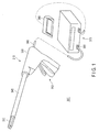
FIG. 1 is a schematic diagram illustrating an exemplary structure of a treatment system according to each exemplary embodiment. -
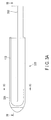
FIG. 2A is a schematic cross-section view illustrating an exemplary structure of a shaft and a holding part in an energy treatment tool according to each exemplary embodiment, which illustrates a state in which the holding part is closed. -
FIG. 2B is a schematic cross-section view illustrating an exemplary structure of the shaft and the holding part in the energy treatment tool according to each exemplary embodiment, which illustrates a state in which the holding part is opened. -
FIG. 3A is a plan view illustrating an exemplary structure of a first holding member in the holding part according to each exemplary embodiment. -
FIG. 3B is a schematic diagram illustrating an exemplary structure of the first holding member in the holding part according to each exemplary embodiment, which is a longitudinal cross-section view along theline 3B-3B illustrated inFIG. 3A . -
FIG. 3C is a schematic diagram illustrating an exemplary structure of the first holding member in the holding part according to each exemplary embodiment, which is a transverse cross-section view along theline 3C-3C illustrated inFIG. 3A . -
FIG. 4 is an exploded perspective view illustrating an exemplary structure of a first electrode part according to a first exemplary embodiment. -
FIG. 5 is a perspective view illustrating an exemplary structure of a first electrode part according to the first exemplary embodiment. -
FIG. 6 is a perspective view illustrating an exemplary structure of a first high frequency electrode, a highly heat-conductive adhesive sheet, an electric resistance pattern, and a first high frequency electrode current line according to the first exemplary embodiment. -
FIG. 7 is a perspective view illustrating an exemplary structure of a first high frequency electrode, a highly heat-conductive adhesive sheet, an electric resistance pattern, and a first high frequency electrode current line according to the second exemplary embodiment. - A first exemplary embodiment according to the present invention will be described with reference to the drawings. A treatment apparatus according to the present exemplary embodiment is used for treating body tissues. The treatment apparatus applies at least one of high frequency energy and thermal energy on body tissues. A
treatment apparatus 300 is schematically illustrated inFIG. 1 . As illustrated, thetreatment apparatus 300 comprises anenergy treatment tool 310, acontrol device 370, and afoot switch 380. - The
energy treatment tool 310 is a linear type surgical treatment tool penetrating through the abdominal wall for treatment, for example. Theenergy treatment tool 310 includes ahandle 350, ashaft 340 attached on thehandle 350, and aholding part 320 provided on the tip end of theshaft 340. Theholding part 320 is a treatment part which is openable and/or closable and is directed to perform treatments such as coagulation and incision of a body tissue by gripping the body tissue to be treated. For the following description, the side of theholding part 320 will be called tip end side and the side of thehandle 350 will be called base end side. Thehandle 350 comprises a plurality ofoperation knobs 352 for operating theholding part 320. - A shape of the
energy treatment tool 310 illustrated herein is exemplary, and any other shape having the same function may be employed. For example, the holding part, the handle, and the operation knobs may have different shapes from the shapes shown inFIG. 1 , and the shaft may be curved. Furthermore, theenergy treatment tool 310 is not limited to a forceps-like shape for gripping body tissues, but may be a trowel-type treatment tool which is pressed against body tissues in use. - The
handle 350 is connected to thecontrol device 370 via acable 360. Herein, thecable 360 and thecontrol device 370 are connected with each other via aconnector 365, and the connection is removable to permit replacement of theenergy treatment tool 310 in accordance with a treatment to be performed. Thecontrol device 370 is connected with thefoot switch 380. The foot-operatedfoot switch 380 may be replaced with a hand-operated switch or another switch. An operator operates the pedal of thefoot switch 380 thereby to switch ON/OFF energy supply from thecontrol device 370 to theenergy treatment tool 310. - An exemplary structure of the
holding part 320 and theshaft 340 is illustrated inFIG. 2A andFIG. 2B .FIG. 2A illustrates a state in which theholding part 320 is closed andFIG. 2B illustrates a state in which theholding part 320 is opened. Theshaft 340 comprises atube 342 and asheath 343. Thetube 342 is fixed at its base end to thehandle 350. Thesheath 343 is slidably arranged on the outer periphery of thetube 342 in the axial direction of thetube 342. - The holding
part 320 is arranged on the tip end of thetube 342. The holdingpart 320 comprises a first holdingmember 322 and asecond holding member 324. The base of the first holdingmember 322 is fixed on the tip end of thetube 342 in theshaft 340. On the other hand, the base of the second holdingmember 324 is rotatably supported on the tip end of thetube 342 in theshaft 340 by asupport pin 346. Therefore, the second holdingmember 324 axially rotates about thesupport pin 346 and opens/closes relative to the first holdingmember 322. - In a state in which the holding
part 320 is closed, a cross-section shape in which the base of the first holdingmember 322 and the base of the second holdingmember 324 are put together is circular. Thesecond holding member 324 is energized by anelastic member 347 such as plate spring to open relative to the first holdingmember 322. When thesheath 343 is slid toward the tip end of thetube 342 so that the base of the first holdingmember 322 and the base of the second holdingmember 324 are covered by thesheath 343, as illustrated inFIG. 2A , the first holdingmember 322 and the second holdingmember 324 are closed against an energizing force of theelastic member 347. On the other hand, when thesheath 343 is slid toward the base end side of thetube 342, as illustrated inFIG. 2B , the second holdingmember 324 is opened relative to the first holdingmember 322 due to an energizing force of theelastic member 347. - The
tube 342 is provided therein with a first high frequency electrodecurrent line 162 connected to a firsthigh frequency electrode 110 and a second high frequency electrode current line 262 connected to a secondhigh frequency electrode 210, which will be described later. In addition, thetube 342 is provided therein with a pair of first heatercurrent lines 164 connected to anelectrothermal conversion element 140 to function as a heat generation member, which is arranged on the firsthigh frequency electrode 110, and a pair of second heater current lines 264 connected to an electrothermal conversion element arranged on a secondhigh frequency electrode 210. - A
drive rod 344 connected on its base end to one of the operation knobs 352 is movably arranged in the axial direction of thetube 342 inside thetube 342. A thin plate-shapedcutter 345 forming a blade on its tip end is arranged on the tip end of thedrive rod 344. When theoperation knob 352 is operated, thecutter 345 is moved in the axial direction of thetube 342 via thedrive rod 344. When thecutter 345 is moved toward the tip end, thecutter 345 is housed in a firstcutter guide groove 332 and a secondcutter guide groove 334 described later formed in the holdingpart 320. - A structure of the first holding
member 322 is schematically illustrated inFIG. 3A ,FIG. 3B andFIG. 3C .FIG. 3A is a plan view of the first holdingmember 322 as viewed from a direction of the firsthigh frequency electrode 110.FIG. 3B is a cross-section view along theline 3B-3B ofFIG. 3A .FIG. 3C is a cross-section view along theline 3C-3C ofFIG. 3A . As illustrated, the first holdingmember 322 is formed with the firstcutter guide groove 332 for guiding thecutter 345. - The
first holding member 322 is provided with the firsthigh frequency electrode 110 including a conductive copper thin plate, for example. The firsthigh frequency electrode 110 is configured to contact with a body tissue on either main surface thereof (which will be called first main surface below). The firsthigh frequency electrode 110 includes the firstcutter guide groove 332, and thus its planar shape is U-shaped as illustrated inFIG. 3A . - The first
high frequency electrode 110 is electrically connected with the first high frequency electrodecurrent line 162 to function as a lead wire for applying a high frequency voltage to the firsthigh frequency electrode 110 in a way described later in detail. The firsthigh frequency electrode 110 is connected to thecontrol device 370 via the first high frequency electrodecurrent line 162 and thecable 360. - The
electrothermal conversion element 140 and acover member 150 are arranged to a second main surface of the firsthigh frequency electrode 110 which does not contact with a body tissue as described later in detail. Afirst electrode part 100 formed of the firsthigh frequency electrode 110, theelectrothermal conversion element 140, thecover member 150 and the like is formed in this way. Thefirst electrode part 100 is embedded in and fixed on a first holding membermain body 326. An exemplary structure of thefirst electrode part 100 will be described below in more detail. - As illustrated in
FIG. 2A andFIG. 2B , the second holdingmember 324 is symmetrical in its shape to the first holdingmember 322, and has the same structure as the first holdingmember 322. That is, the second holdingmember 324 is formed with the secondcutter guide groove 334 opposite to the firstcutter guide groove 332. Thesecond holding member 324 is provided with the secondhigh frequency electrode 210 opposite to the firsthigh frequency electrode 110. The secondhigh frequency electrode 210 is configured to contact with a body tissue on either main surface thereof. The secondhigh frequency electrode 210 is connected to thecontrol device 370 via the second high frequency electrode current line 262 and thecable 360. - The electrothermal conversion element and a cover member are arranged to a surface of the second
high frequency electrode 210 which does not contact with a body tissue. Asecond electrode part 200 formed of the secondhigh frequency electrode 210, the electrothermal conversion element, the cover member and the like is formed in this way. Thesecond electrode part 200 is embedded in and fixed on a second holding membermain body 328. - The
first electrode part 100 will be described in detail. Thesecond electrode part 200 has the same structure as thefirst electrode part 100, and thus the description of thesecond electrode part 200 will be omitted. An exploded perspective view of thefirst electrode part 100 is illustrated inFIG. 4 . As illustrated, thefirst electrode part 100 includes the firsthigh frequency electrode 110, a highly heat-conductive adhesive sheet 130, theelectrothermal conversion element 140, and thecover member 150. Theelectrothermal conversion element 140 includes asubstrate 142 and anelectric resistance pattern 144. A perspective view of thefirst electrode part 100 assembled from the firsthigh frequency electrode 110, the highly heat-conductive adhesive sheet 130, theelectrothermal conversion element 140, and thecover member 150 is illustrated inFIG. 5 . - As illustrated in
FIG. 4 , the firsthigh frequency electrode 110, the highly heat-conductive adhesive sheet 130, and theelectrothermal conversion element 140 have a U shape to form the firstcutter guide groove 332. Thecover member 150 has a shape including a groove to form the firstcutter guide groove 332. As illustrated inFIG. 5 , thefirst electrode part 100 forms the firstcutter guide groove 332 as a whole. In addition, the first high frequency electrodecurrent line 162 and first heatercurrent lines 164 extend from a base end of thefirst electrode part 100. - As illustrated in
FIG. 4 , theelectrothermal conversion element 140 has asubstrate 142 including polyimide, for example. The shape of thesubstrate 142 generally matches with the shape of the firsthigh frequency electrode 110 as illustrated inFIG. 4 . Thesubstrate 142 is slightly larger in length and slightly smaller in width than the firsthigh frequency electrode 110. Parts of theelectrothermal conversion element 140 that protrude from the firsthigh frequency electrode 110 are referred to as extension parts. - An
electric resistance pattern 144 is formed of a stainless (SUS) pattern, for example, in most of thesubstrate 142 except the extension parts. Firstlead connections 146 connected to both ends of theelectric resistance pattern 144 are formed of a SUS pattern at the ends including the extension parts of thesubstrate 142. When a voltage is applied to a pair offirst lead connections 146, theelectric resistance pattern 144 generates heat. In this way, theelectrothermal conversion element 140 functions as a sheet heater. A thickness of theelectrothermal conversion element 140 is around 100 µm, for example. - The first
high frequency electrode 110 and theelectrothermal conversion element 140 are adhered to each other by the highly heat-conductive adhesive sheet 130. Herein, theelectrothermal conversion element 140 is adhered with the surface forming theelectric resistance pattern 144 thereon faced toward the firsthigh frequency electrode 110. The highly heat-conductive adhesive sheet 130 is a sheet which is high in thermal conductivity and resistant to high temperature and has an adhesive property. The highly heat-conductive adhesive sheet 130 is made by mixing highly heat-conductive ceramic such as alumina or aluminum nitride with epoxy resin, for example. The highly heat-conductive adhesive sheet 130 has a high adhesive property, preferable thermal conductivity and an electric insulation property. A thickness of the highly heat-conductive adhesive sheet 130 is around 50 µm, for example. - The highly heat-
conductive adhesive sheet 130 has substantially the same shape as the firsthigh frequency electrode 110. The highly heat-conductive adhesive sheet 130 is slightly longer than the firsthigh frequency electrode 110. Since the highly heat-conductive adhesive sheet 130 is longer than the firsthigh frequency electrode 110, an electric insulation property between the firsthigh frequency electrode 110 and thefirst lead connections 146 is secured. - The pair of first heater
current lines 164 is connected to the pair offirst lead connections 146. The first heatercurrent lines 164 are connected to the surface with theelectric resistance pattern 144 of theelectrothermal conversion element 140 formed thereon, that is the surface opposed to the firsthigh frequency electrode 110. A voltage is applied to theelectric resistance pattern 144 from the first heatercurrent lines 164 via thefirst lead connections 146 so that theelectric resistance pattern 144 generates heat and the heat is transferred to the body tissue via the firsthigh frequency electrode 110. - The
electric resistance pattern 144 of theelectrothermal conversion element 140 is arranged closer to the firsthigh frequency electrode 110 than to thesubstrate 142 of theelectrothermal conversion element 140, and arranged with the highly heat-conductive adhesive sheet 130 intervened between theelectric resistance pattern 144 and the firsthigh frequency electrode 110. Thus, theelectric resistance pattern 144 is thermally coupled with the firsthigh frequency electrode 110 via the highly heat-conductive adhesive sheet 130. Only the highly heat-conductive adhesive sheet 130 is present between theelectric resistance pattern 144 and the firsthigh frequency electrode 110, and thus heat generated by theelectric resistance pattern 144 is efficiently transferred to the firsthigh frequency electrode 110. The heat transferred to the firsthigh frequency electrode 110 is transferred to a body tissue gripped by a holdingpart 320. As described above, the firsthigh frequency electrode 110 also functions as a heat transfer plate to transfer the heat. - The first high frequency electrode
current line 162 is further connected to the firsthigh frequency electrode 110. The first high frequency electrodecurrent line 162 is connected by soldering, for example, to a part of the second main surface of the firsthigh frequency electrode 110, to which the highly heat-conductive adhesive sheet 130 and theelectrothermal conversion element 140 are not adhered. A high frequency voltage is applied to the firsthigh frequency electrode 110 from the first high frequency electrodecurrent line 162 so that the firsthigh frequency electrode 110 applies a high frequency current to a body tissue gripped by the holdingpart 320. - The
cover member 150 is made of heat-resistant resin. Thecover member 150 has a shape corresponding to the firsthigh frequency electrode 110. A thickness of thecover member 150 is about 0.3 mm, for example. - In order to efficiently transfer heat generated by the
electrothermal conversion element 140 to the firsthigh frequency electrode 110, it is preferable that thecover member 150 and the first holding membermain body 326 around the same have lower thermal conductivity than the firsthigh frequency electrode 110 or the highly heat-conductive adhesive sheet 130. Thecover member 150 and the first holding membermain body 326 have low thermal conductivity so that loss of the heat generated by theelectrothermal conversion element 140 is decreased. - The first
high frequency electrode 110, theelectric resistance pattern 144 of theelectrothermal conversion element 140, and the first high frequency electrodecurrent line 162 will be described in more detail. An arrangement of theelectric resistance pattern 144 on the firsthigh frequency electrode 110 and the first high frequency electrodecurrent line 162 is illustrated inFIG. 6 . While the highly heat-conductive adhesive sheet 130 is illustrated in the figure, for simplification, thesubstrate 142 of theelectrothermal conversion element 140 is not illustrated. - As illustrated in
FIG. 6 , the first high frequency electrodecurrent line 162 is arranged along theelectrothermal conversion element 140 beside theelectrothermal conversion element 140, parallel to a longitudinal direction of the firsthigh frequency electrode 110. In addition, an electrical connection between the firsthigh frequency electrode 110 and the first high frequency electrodecurrent line 162 is arranged around the center with respect to the longitudinal direction of the firsthigh frequency electrode 110. The electrical connection between the firsthigh frequency electrode 110 and the first high frequency electrodecurrent line 162 corresponds to a side of the region with theelectric resistance pattern 144 formed in theelectrothermal conversion element 140. - In addition, the
electric resistance pattern 144 is formed in a corrugated shape. The line width of theelectric resistance pattern 144 is uniform entirely. On the other hand, theelectric resistance pattern 144 is formed such that the density thereof is higher on the side where the first high frequency electrodecurrent line 162 is arranged with the firstcutter guide groove 332 interposed therebetween, than on the side where the first high frequency electrodecurrent line 162 is not arranged. More specifically, the pitch of theelectric resistance pattern 144 formed around the first high frequency electrodecurrent line 162 arranged is smaller than the pitch of the other part. - By forming the
electric resistance pattern 144 as described above, the heat generation density of theelectrothermal conversion element 140 increases in the part where theelectric resistance pattern 144 is densely formed. More specifically, the heat generation density around which the first high frequency electrodecurrent line 162 is arranged is higher than the heat generation density of the other part. - The
first electrode part 100 has been described above, and thesecond electrode part 200 is the same as thefirst electrode part 100. - The operations of the
treatment apparatus 300 according to the present exemplary embodiment will be described below. The operator previously operates the input part of thecontrol device 370 to set the output conditions of thetreatment apparatus 300, such as setting power for high frequency energy output, target temperature for thermal energy output, and heating time. Thetreatment apparatus 300 may be configured such that the respective values are independently set or a set of setting values is selected depending on an operation. - The holding
part 320 and theshaft 340 in theenergy treatment tool 310 are inserted into the abdominal cavity via the peritoneum, for example. The operator operates the operation knobs 352 to open/close the holdingpart 320 so that a body tissue to be treated is gripped by the first holdingmember 322 and the second holdingmember 324. At this time, the body tissue to be treated contacts on the first main surfaces of both of the firsthigh frequency electrode 110 provided on the first holdingmember 322 and the secondhigh frequency electrode 210 provided on the second holdingmember 324. - When the body tissue to be treated is gripped by the holding
part 320, the operator operates thefoot switch 380. When thefoot switch 380 is tuned ON, high frequency power for preset power is supplied from thecontrol device 370 to the firsthigh frequency electrode 110 and the secondhigh frequency electrode 210 via the first high frequency electrodecurrent line 162 passing inside thecable 360 and the second high frequency electrode current line 262. The supplied power is approximately 20 W to 80 W, for example. Consequently, the body tissue generates heat and the tissue is cauterized. The tissue modifies and coagulates due to the cauterization. - After the
control device 370 stops outputting high frequency energy, theelectrothermal conversion element 140 is supplied with power such that the temperature of the firsthigh frequency electrode 110 reaches a target temperature. Herein, the target temperature is 200°C, for example. At this time, a current flows through theelectric resistance pattern 144 of theelectrothermal conversion element 140 from thecontrol device 370 via thecable 360 and the first heatercurrent lines 164. Theelectric resistance pattern 144 generates heat due to the current. The heat generated by theelectric resistance pattern 144 is transferred to the firsthigh frequency electrode 110 via the highly heat-conductive adhesive sheet 130. Consequently, the temperature of the firsthigh frequency electrode 110 increases. - Similarly, the electrothermal conversion element in the
second electrode part 200 is supplied with power such that a temperature of the secondhigh frequency electrode 210 reaches the target temperature. The electrothermal conversion element in thesecond electrode part 200 is supplied with power from thecontrol device 370 via thecable 360 and the second heater current lines 264 so that the temperature of the secondhigh frequency electrode 210 increases. - The body tissue contacting with the first
high frequency electrode 110 or the secondhigh frequency electrode 210 is further cauterized and further coagulated by the heat. When the body tissue coagulates by the heating, thecontrol device 370 stops the output of thermal energy. The operator finally operates the operation knobs 352 to move thecutter 345, thereby cutting the body tissue. The treatment of the body tissue is completed with the above operations. - In the
first electrode part 100 according to the exemplary embodiment, a high voltage is applied to the firsthigh frequency electrode 110. For this reason, a relatively thick conducting wire is used for the first high frequency electrodecurrent line 162. The first high frequency electrodecurrent line 162 is a thick conducting wire, and thus excellent in thermal conductivity. Thus, the temperature of the firsthigh frequency electrode 110 is likely to fall in the vicinity of the first high frequency electrodecurrent line 162, due to the thermal conduction through the first high frequency electrodecurrent line 162. - Therefore, according to the present exemplary embodiment, as explained with reference to
FIG. 6 , the density of theelectric resistance pattern 144 formed around which the first high frequency electrodecurrent line 162 is arranged is higher than that of the other part. The density of theelectric resistance pattern 144 is higher than that of the other part, and the heat generation density of theelectrothermal conversion element 140 in the vicinity of the first high frequency electrodecurrent line 162 is thus higher than the heat generation density of the other part of theelectrothermal conversion element 140. Consequently, the temperature of the firsthigh frequency electrode 110 in the vicinity of the first high frequency electrodecurrent line 162 is sufficiently increased in spite of release of heat by the first high frequency electrodecurrent line 162. More specifically, the difference in temperature is small in the firsthigh frequency electrode 110. The same applies to thesecond electrode part 200. - Further, according to the present exemplary embodiment, the
electric resistance pattern 144 formed for theelectrothermal conversion element 140 is formed such that the density of the side where the first high frequency electrodecurrent line 162 is arranged with the firstcutter guide groove 332 interposed therebetween is higher than the density of the side where the first high frequency electrodecurrent line 162 is not arranged. However, without limitation thereto, for example, theelectric resistance pattern 144 may be densely formed in the vicinity of the first high frequency electrodecurrent line 162 on the side where the first high frequency electrodecurrent line 162 is arranged from the firstcutter guide groove 332, whereas theelectric resistance pattern 144 may be sparsely formed at the part away from the first high frequency electrodecurrent line 162. More specifically, theelectric resistance pattern 144 may be formed such that the heat generation density is high in the vicinity of the first high frequency electrodecurrent line 162, whereas theelectric resistance pattern 144 may be formed such that the heat generation density is low at the part away from the first high frequency electrodecurrent line 162. - In addition, heat is likely to be released at ends such as the tip end and base end of the first
high frequency electrode 110. Thus, for compensating for the released heat, theelectric resistance pattern 144 may be densely formed at an end of theelectrothermal conversion element 140 to increase the heat generation density. As described above, the temperature of the firsthigh frequency electrode 110 can become uniform, with the heat generation density increased by formation of theelectric resistance pattern 144 more densely in locations where the heat of the firsthigh frequency electrode 110 is likely to be released than at the other part. While an example of the fact that the heat generation density around the first high frequency electrodecurrent line 162 arranged is higher than the heat generation density at the other part has been presented in the present exemplary embodiment, the present exemplary embodiment never exclude the inclusion of a part with a significantly higher heat generation density. - As described above, when the region where the
electric resistance pattern 144 of theelectrothermal conversion element 140 is formed regarded as a pattern region in thefirst electrode part 100 according to the present exemplary embodiment, the heat generation density associated with theelectric resistance pattern 144 in a first region including a region where the distance from the first high frequency electrodecurrent line 162 is smaller than a predetermined value is higher than the heat generation density associated with theelectric resistance pattern 144 in a second region including at least a part of the pattern region other than the first region. In addition, the heat generation density associated with theelectric resistance pattern 144 in a third region including a region where the distance from an end of the firsthigh frequency electrode 110 is smaller than a predetermined value is higher than the heat generation associated with theelectric resistance pattern 144 in the second region. - Further, the present exemplary embodiment has provided, but not limited to, the example where the first high frequency electrode
current line 162 is connected to the firsthigh frequency electrode 110 around the center of the firsthigh frequency electrode 110 with respect to the longitudinal direction. The first high frequency electrodecurrent line 162 just has to be provided in the vicinity of a region of theelectric resistance pattern 144 formed in theelectrothermal conversion element 140, and theelectric resistance pattern 144 in the vicinity of the first high frequency electrodecurrent line 162 just has to be densely formed thatelectric resistance pattern 144 in at least a region of the other part. - According to the present exemplary embodiment, as illustrated in
FIG. 6 and the like, the pitch of theelectric resistance pattern 144 formed in a corrugated shape is varied to cause the heat generation density to differ depending on sites of theelectrothermal conversion element 140, thereby making the temperature of the firsthigh frequency electrode 110 uniform. However, the method for varying the heat generation density is not limited thereto. For example, for a region where the heat generation density is desired to be increased in theelectrothermal conversion element 140, the line width of theelectric resistance pattern 144 may be reduced to increase the electric resistance, and thus increase the amount of heat generation of theelectrothermal conversion element 140. Alternatively, the amount of heat generation may be adjusted by adjusting both the pitch and line width of theelectric resistance pattern 144. - A second exemplary embodiment will be described. Herein, the differences from the first exemplary embodiment will be described, and the same parts are denoted with the same reference numerals and the description thereof will be omitted. In the present exemplary embodiment, a
first electrode part 100 differs from thefirst electrode part 100 according the first exemplary embodiment in the structure of firsthigh frequency electrode 110,electrothermal conversion element 140, and first high frequency electrodecurrent line 162. - The structures of the first
high frequency electrode 110,electrothermal conversion element 140, first high frequency electrodecurrent line 162, and the like in thefirst electrode part 100 according to the present embodiment are illustrated inFIG. 7 . As illustrated inFIG. 7 , theelectrothermal conversion element 140 and highly heat-conductive adhesive sheet 130 according to the present exemplary embodiment are provided with acutout part 148. The first high frequency electrodecurrent line 162 is connected to the firsthigh frequency electrode 110 at thecutout part 148. In addition, theelectric resistance pattern 144 of theelectrothermal conversion element 140 according to the present exemplary embodiment is densely formed in the vicinity of thecutout part 148 more than at the other part. - In accordance with the present exemplary embodiment, the first high frequency electrode
current line 162 is connected to the firsthigh frequency electrode 110 at thecutout part 148, and thus, at the part, heat is likely to be released from the first high frequency electrodecurrent line 162. In addition, at thecutout part 148, because of the reduced region where theelectric resistance pattern 144 is formed, the amount of heat generation is likely to be relatively lowered. Therefore, according to the present exemplary embodiment, theelectric resistance pattern 144 is densely formed in the region with thecutout part 148. More specifically, the density of heat generation by theelectric resistance pattern 144 is higher in the region with thecutout part 148 than in other region. - The first high frequency electrode
current line 162 can be arranged to have an overlap with theelectrothermal conversion element 140, by providing theelectrothermal conversion element 140 with thecutout part 148 as in the present exemplary embodiment. Consequently, thefirst electrode part 100 can be reduced in size. In addition, the heat generation density of theelectrothermal conversion element 140 is adjusted to compensate for a decrease in heat generation density, which is caused by providing theelectrothermal conversion element 140 with thecutout part 148, and release of heat, which is caused by the presence of the first high frequency electrodecurrent line 162. Therefore, the firsthigh frequency electrode 110 is less likely to produce a difference in temperature. - An example of providing a cutout part at an edge of the
electrothermal conversion element 140 has been given as illustrated inFIG. 7 in the present exemplary embodiment. However, without limitation thereto, the first high frequency electrodecurrent line 162 may be connected to the firsthigh frequency electrode 110 at an opening provided in theelectrothermal conversion element 140 in place of the cutout part. -
- 100
- first electrode part
- 110
- first high frequency electrode
- 130
- highly heat-conductive adhesive sheet
- 140
- electrothermal conversion element
- 142
- substrate
- 144
- electric resistance pattern
- 146
- lead connection
- 148
- cutout part
- 150
- cover member
- 162
- first high frequency electrode current line
- 164
- first heater current line
- 200
- second electrode part
- 210
- second high frequency electrode
- 262
- second high frequency electrode current line
- 264
- second heater current line
- 300
- treatment apparatus
- 310
- energy treatment tool
- 320
- holding part
- 322
- first holding member
- 324
- second holding member
- 326
- first holding member main body
- 328
- second holding member main body
- 332
- first cutter guide groove
- 334
- second cutter guide groove
- 340
- shaft
- 342
- tube
- 343
- sheath
- 344
- drive rod
- 345
- cutter
- 346
- support pin
- 347
- elastic member
- 350
- handle
- 352
- operation knob
- 360
- cable
- 365
- connector
- 370
- control device
- 380
- foot switch
Claims (5)
- A treatment apparatus configured to treat a body tissue, the treatment apparatus comprising:a conductive heat transfer plate configured to transfer heat and power to the body tissue in contact with the body tissue;an electrothermal conversion element provided on the heat transfer plate, the electrothermal conversion element comprising an electric resistance pattern that generates heat with a voltage applied; anda lead wire configured to supply an electric current to the heat transfer plate, whereinheat generation density by the electric resistance pattern in a first region of a pattern region where the electric resistance pattern of the electrothermal conversion element is formed, the first region comprising a region where a distance from the lead wire is smaller than a predetermined value, is higher than heat generation density by the electric resistance pattern in a second region comprising at least a part of the pattern region other than the first region.
- The treatment apparatus according to claim 1, wherein the electric resistance pattern in the first region has a smaller pitch than the electric resistance pattern in the second region, thereby the heat generation density of the first region thus is higher than the heat generation density of the second region.
- The treatment apparatus according to claim 1, wherein the electric resistance pattern in the first region has a smaller line width than the electric resistance pattern in the second region, thereby the heat generation density of the first region is higher than the heat generation density of the second region.
- The treatment apparatus according to any one of claims 1 to 3, wherein
the electrothermal conversion element is provided with a cutout part or an opening, and
the lead wire is connected to the heat transfer plate at the cutout part or the opening. - The treatment apparatus according to any one of claims 1 to 3, wherein heat generation density by the electric resistance pattern in a third region of the pattern region, the third region comprising a region where a distance from an end of the heat transfer plate is smaller than a predetermined value is higher than heat generation density by the electric resistance pattern in the second region.
Applications Claiming Priority (2)
| Application Number | Priority Date | Filing Date | Title |
|---|---|---|---|
| JP2014011843A JP6274881B2 (en) | 2014-01-24 | 2014-01-24 | Therapeutic treatment device |
| PCT/JP2015/051700 WO2015111662A1 (en) | 2014-01-24 | 2015-01-22 | Therapeutic apparatus |
Publications (2)
| Publication Number | Publication Date |
|---|---|
| EP3097880A1 true EP3097880A1 (en) | 2016-11-30 |
| EP3097880A4 EP3097880A4 (en) | 2017-09-27 |
Family
ID=53681463
Family Applications (1)
| Application Number | Title | Priority Date | Filing Date |
|---|---|---|---|
| EP15740270.2A Withdrawn EP3097880A4 (en) | 2014-01-24 | 2015-01-22 | Therapeutic apparatus |
Country Status (5)
| Country | Link |
|---|---|
| US (1) | US20160324566A1 (en) |
| EP (1) | EP3097880A4 (en) |
| JP (1) | JP6274881B2 (en) |
| CN (1) | CN106413612A (en) |
| WO (1) | WO2015111662A1 (en) |
Families Citing this family (9)
| Publication number | Priority date | Publication date | Assignee | Title |
|---|---|---|---|---|
| JPWO2017163410A1 (en) * | 2016-03-25 | 2019-01-24 | オリンパス株式会社 | Energy treatment tool |
| WO2018150532A1 (en) | 2017-02-17 | 2018-08-23 | オリンパス株式会社 | Treatment tool |
| WO2018185815A1 (en) | 2017-04-03 | 2018-10-11 | オリンパス株式会社 | Heat treatment tool |
| WO2018189884A1 (en) * | 2017-04-14 | 2018-10-18 | オリンパス株式会社 | Treatment tool |
| US11648047B2 (en) | 2017-10-06 | 2023-05-16 | Vive Scientific, Llc | System and method to treat obstructive sleep apnea |
| CN112638296B (en) * | 2018-08-31 | 2024-10-18 | 奥林巴斯株式会社 | Medical heater, treatment device, and method for manufacturing the treatment device |
| JP7044895B2 (en) * | 2018-09-11 | 2022-03-30 | オリンパス株式会社 | Medical heaters, treatment tools, and methods for manufacturing treatment tools |
| WO2023148632A1 (en) * | 2022-02-01 | 2023-08-10 | Covidien Lp | Thermal elements for surgical instruments and surgical instruments incorporating the same |
| WO2024150187A1 (en) * | 2023-01-13 | 2024-07-18 | Covidien Lp | Surgical instruments, systems, and methods incorporating ultrasonic energy and thermal heating functionality |
Family Cites Families (14)
| Publication number | Priority date | Publication date | Assignee | Title |
|---|---|---|---|---|
| JP2600835B2 (en) * | 1988-08-25 | 1997-04-16 | 東芝ライテック株式会社 | Fixing heating element, fixing device, and image forming apparatus |
| JP2527836B2 (en) * | 1990-08-17 | 1996-08-28 | 日本碍子株式会社 | Semiconductor wafer-heating device |
| JPH08250266A (en) * | 1995-03-15 | 1996-09-27 | Ushio Inc | Rod-shaped heating element |
| JP2002141163A (en) * | 2000-10-31 | 2002-05-17 | Kyocera Corp | Ceramic heater and optical multiplexer / demultiplexer using the same |
| US9642669B2 (en) * | 2008-04-01 | 2017-05-09 | Olympus Corporation | Treatment system, and treatment method for living tissue using energy |
| JP5687462B2 (en) * | 2010-09-27 | 2015-03-18 | オリンパス株式会社 | Therapeutic treatment device |
| JP5622551B2 (en) * | 2010-12-14 | 2014-11-12 | オリンパス株式会社 | THERAPEUTIC TREATMENT DEVICE AND ITS CONTROL METHOD |
| JP5631716B2 (en) * | 2010-12-14 | 2014-11-26 | オリンパス株式会社 | Therapeutic treatment device |
| US9615877B2 (en) * | 2011-06-17 | 2017-04-11 | Covidien Lp | Tissue sealing forceps |
| JP5814685B2 (en) * | 2011-08-05 | 2015-11-17 | オリンパス株式会社 | Therapeutic treatment device |
| US9526558B2 (en) * | 2011-09-13 | 2016-12-27 | Domain Surgical, Inc. | Sealing and/or cutting instrument |
| JP2013106909A (en) * | 2011-11-24 | 2013-06-06 | Olympus Medical Systems Corp | Therapeutic treatment apparatus |
| US9011435B2 (en) * | 2012-02-24 | 2015-04-21 | Covidien Lp | Method for manufacturing vessel sealing instrument with reduced thermal spread |
| US20150060527A1 (en) * | 2013-08-29 | 2015-03-05 | Weihua Tang | Non-uniform heater for reduced temperature gradient during thermal compression bonding |
-
2014
- 2014-01-24 JP JP2014011843A patent/JP6274881B2/en active Active
-
2015
- 2015-01-22 WO PCT/JP2015/051700 patent/WO2015111662A1/en not_active Ceased
- 2015-01-22 CN CN201580005473.3A patent/CN106413612A/en active Pending
- 2015-01-22 EP EP15740270.2A patent/EP3097880A4/en not_active Withdrawn
-
2016
- 2016-07-22 US US15/216,846 patent/US20160324566A1/en not_active Abandoned
Also Published As
| Publication number | Publication date |
|---|---|
| EP3097880A4 (en) | 2017-09-27 |
| WO2015111662A1 (en) | 2015-07-30 |
| JP2015136604A (en) | 2015-07-30 |
| US20160324566A1 (en) | 2016-11-10 |
| JP6274881B2 (en) | 2018-02-07 |
| CN106413612A (en) | 2017-02-15 |
Similar Documents
| Publication | Publication Date | Title |
|---|---|---|
| EP3097880A1 (en) | Therapeutic apparatus | |
| EP2952149B1 (en) | Therapeutic treatment device | |
| EP2939625B1 (en) | Therapeutic treatment device | |
| JP5931604B2 (en) | Therapeutic treatment device | |
| JP5814685B2 (en) | Therapeutic treatment device | |
| JP5797348B2 (en) | THERAPEUTIC TREATMENT DEVICE AND MANUFACTURING METHOD THEREOF | |
| WO2012161163A1 (en) | Therapeutic treatment apparatus | |
| CN109475380B (en) | disposal device | |
| US7458969B2 (en) | Therapeutic device for tissue from living body | |
| JP2013106909A (en) | Therapeutic treatment apparatus | |
| US20170215937A1 (en) | Therapeutic treatment device | |
| JP5767053B2 (en) | Therapeutic treatment device | |
| JP2013034614A (en) | Therapeutical treatment apparatus | |
| JP2012161566A (en) | Therapeutical treatment device and method for controlling the same | |
| JP5704985B2 (en) | Therapeutic treatment device | |
| WO2018055778A1 (en) | Treatment instrument and treatment system | |
| JP2012249807A (en) | Treatment apparatus for therapy, and control method for the same | |
| WO2018193493A1 (en) | Surgical tool | |
| JP2014023757A (en) | Medical treatment device and control method of the same | |
| WO2014148199A1 (en) | Therapeutic treatment device |
Legal Events
| Date | Code | Title | Description |
|---|---|---|---|
| PUAI | Public reference made under article 153(3) epc to a published international application that has entered the european phase |
Free format text: ORIGINAL CODE: 0009012 |
|
| 17P | Request for examination filed |
Effective date: 20160818 |
|
| AK | Designated contracting states |
Kind code of ref document: A1 Designated state(s): AL AT BE BG CH CY CZ DE DK EE ES FI FR GB GR HR HU IE IS IT LI LT LU LV MC MK MT NL NO PL PT RO RS SE SI SK SM TR |
|
| AX | Request for extension of the european patent |
Extension state: BA ME |
|
| DAX | Request for extension of the european patent (deleted) | ||
| A4 | Supplementary search report drawn up and despatched |
Effective date: 20170828 |
|
| RIC1 | Information provided on ipc code assigned before grant |
Ipc: A61B 18/12 20060101AFI20170821BHEP |
|
| GRAP | Despatch of communication of intention to grant a patent |
Free format text: ORIGINAL CODE: EPIDOSNIGR1 |
|
| STAA | Information on the status of an ep patent application or granted ep patent |
Free format text: STATUS: GRANT OF PATENT IS INTENDED |
|
| INTG | Intention to grant announced |
Effective date: 20190220 |
|
| STAA | Information on the status of an ep patent application or granted ep patent |
Free format text: STATUS: THE APPLICATION IS DEEMED TO BE WITHDRAWN |
|
| 18D | Application deemed to be withdrawn |
Effective date: 20190703 |