EP3097845A1 - Light source module and endoscope light source system - Google Patents
Light source module and endoscope light source system Download PDFInfo
- Publication number
- EP3097845A1 EP3097845A1 EP15740283.5A EP15740283A EP3097845A1 EP 3097845 A1 EP3097845 A1 EP 3097845A1 EP 15740283 A EP15740283 A EP 15740283A EP 3097845 A1 EP3097845 A1 EP 3097845A1
- Authority
- EP
- European Patent Office
- Prior art keywords
- light
- light source
- irradiation
- side connection
- module
- Prior art date
- Legal status (The legal status is an assumption and is not a legal conclusion. Google has not performed a legal analysis and makes no representation as to the accuracy of the status listed.)
- Withdrawn
Links
- 230000003287 optical effect Effects 0.000 claims description 110
- 239000013307 optical fiber Substances 0.000 claims description 43
- 239000000835 fiber Substances 0.000 claims description 42
- 230000008878 coupling Effects 0.000 claims description 33
- 238000010168 coupling process Methods 0.000 claims description 33
- 238000005859 coupling reaction Methods 0.000 claims description 33
- 238000005286 illumination Methods 0.000 claims description 13
- 238000006243 chemical reaction Methods 0.000 description 18
- 239000006059 cover glass Substances 0.000 description 10
- 238000001228 spectrum Methods 0.000 description 7
- 238000003780 insertion Methods 0.000 description 6
- 230000037431 insertion Effects 0.000 description 6
- 230000000694 effects Effects 0.000 description 5
- 230000005855 radiation Effects 0.000 description 5
- 238000003384 imaging method Methods 0.000 description 4
- 238000009792 diffusion process Methods 0.000 description 2
- 238000006073 displacement reaction Methods 0.000 description 2
- 239000000463 material Substances 0.000 description 2
- 230000002093 peripheral effect Effects 0.000 description 2
- 239000002699 waste material Substances 0.000 description 2
- 239000000853 adhesive Substances 0.000 description 1
- 230000001070 adhesive effect Effects 0.000 description 1
- 230000015572 biosynthetic process Effects 0.000 description 1
- 210000004204 blood vessel Anatomy 0.000 description 1
- 239000000919 ceramic Substances 0.000 description 1
- 229910019990 cerium-doped yttrium aluminum garnet Inorganic materials 0.000 description 1
- 230000001427 coherent effect Effects 0.000 description 1
- 230000006866 deterioration Effects 0.000 description 1
- 238000003745 diagnosis Methods 0.000 description 1
- 229910052736 halogen Inorganic materials 0.000 description 1
- 150000002367 halogens Chemical class 0.000 description 1
- 238000002496 oximetry Methods 0.000 description 1
- 238000002560 therapeutic procedure Methods 0.000 description 1
Images




Classifications
-
- A—HUMAN NECESSITIES
- A61—MEDICAL OR VETERINARY SCIENCE; HYGIENE
- A61B—DIAGNOSIS; SURGERY; IDENTIFICATION
- A61B1/00—Instruments for performing medical examinations of the interior of cavities or tubes of the body by visual or photographical inspection, e.g. endoscopes; Illuminating arrangements therefor
- A61B1/06—Instruments for performing medical examinations of the interior of cavities or tubes of the body by visual or photographical inspection, e.g. endoscopes; Illuminating arrangements therefor with illuminating arrangements
- A61B1/0661—Endoscope light sources
- A61B1/0669—Endoscope light sources at proximal end of an endoscope
-
- A—HUMAN NECESSITIES
- A61—MEDICAL OR VETERINARY SCIENCE; HYGIENE
- A61B—DIAGNOSIS; SURGERY; IDENTIFICATION
- A61B1/00—Instruments for performing medical examinations of the interior of cavities or tubes of the body by visual or photographical inspection, e.g. endoscopes; Illuminating arrangements therefor
- A61B1/00002—Operational features of endoscopes
- A61B1/00004—Operational features of endoscopes characterised by electronic signal processing
- A61B1/00006—Operational features of endoscopes characterised by electronic signal processing of control signals
-
- A—HUMAN NECESSITIES
- A61—MEDICAL OR VETERINARY SCIENCE; HYGIENE
- A61B—DIAGNOSIS; SURGERY; IDENTIFICATION
- A61B1/00—Instruments for performing medical examinations of the interior of cavities or tubes of the body by visual or photographical inspection, e.g. endoscopes; Illuminating arrangements therefor
- A61B1/00064—Constructional details of the endoscope body
- A61B1/00105—Constructional details of the endoscope body characterised by modular construction
-
- A—HUMAN NECESSITIES
- A61—MEDICAL OR VETERINARY SCIENCE; HYGIENE
- A61B—DIAGNOSIS; SURGERY; IDENTIFICATION
- A61B1/00—Instruments for performing medical examinations of the interior of cavities or tubes of the body by visual or photographical inspection, e.g. endoscopes; Illuminating arrangements therefor
- A61B1/06—Instruments for performing medical examinations of the interior of cavities or tubes of the body by visual or photographical inspection, e.g. endoscopes; Illuminating arrangements therefor with illuminating arrangements
- A61B1/063—Instruments for performing medical examinations of the interior of cavities or tubes of the body by visual or photographical inspection, e.g. endoscopes; Illuminating arrangements therefor with illuminating arrangements for monochromatic or narrow-band illumination
-
- A—HUMAN NECESSITIES
- A61—MEDICAL OR VETERINARY SCIENCE; HYGIENE
- A61B—DIAGNOSIS; SURGERY; IDENTIFICATION
- A61B1/00—Instruments for performing medical examinations of the interior of cavities or tubes of the body by visual or photographical inspection, e.g. endoscopes; Illuminating arrangements therefor
- A61B1/06—Instruments for performing medical examinations of the interior of cavities or tubes of the body by visual or photographical inspection, e.g. endoscopes; Illuminating arrangements therefor with illuminating arrangements
- A61B1/0638—Instruments for performing medical examinations of the interior of cavities or tubes of the body by visual or photographical inspection, e.g. endoscopes; Illuminating arrangements therefor with illuminating arrangements providing two or more wavelengths
-
- A—HUMAN NECESSITIES
- A61—MEDICAL OR VETERINARY SCIENCE; HYGIENE
- A61B—DIAGNOSIS; SURGERY; IDENTIFICATION
- A61B1/00—Instruments for performing medical examinations of the interior of cavities or tubes of the body by visual or photographical inspection, e.g. endoscopes; Illuminating arrangements therefor
- A61B1/06—Instruments for performing medical examinations of the interior of cavities or tubes of the body by visual or photographical inspection, e.g. endoscopes; Illuminating arrangements therefor with illuminating arrangements
- A61B1/0646—Instruments for performing medical examinations of the interior of cavities or tubes of the body by visual or photographical inspection, e.g. endoscopes; Illuminating arrangements therefor with illuminating arrangements with illumination filters
-
- A—HUMAN NECESSITIES
- A61—MEDICAL OR VETERINARY SCIENCE; HYGIENE
- A61B—DIAGNOSIS; SURGERY; IDENTIFICATION
- A61B1/00—Instruments for performing medical examinations of the interior of cavities or tubes of the body by visual or photographical inspection, e.g. endoscopes; Illuminating arrangements therefor
- A61B1/06—Instruments for performing medical examinations of the interior of cavities or tubes of the body by visual or photographical inspection, e.g. endoscopes; Illuminating arrangements therefor with illuminating arrangements
- A61B1/07—Instruments for performing medical examinations of the interior of cavities or tubes of the body by visual or photographical inspection, e.g. endoscopes; Illuminating arrangements therefor with illuminating arrangements using light-conductive means, e.g. optical fibres
-
- G—PHYSICS
- G02—OPTICS
- G02B—OPTICAL ELEMENTS, SYSTEMS OR APPARATUS
- G02B23/00—Telescopes, e.g. binoculars; Periscopes; Instruments for viewing the inside of hollow bodies; Viewfinders; Optical aiming or sighting devices
- G02B23/24—Instruments or systems for viewing the inside of hollow bodies, e.g. fibrescopes
- G02B23/2407—Optical details
- G02B23/2461—Illumination
- G02B23/2469—Illumination using optical fibres
-
- G—PHYSICS
- G02—OPTICS
- G02B—OPTICAL ELEMENTS, SYSTEMS OR APPARATUS
- G02B23/00—Telescopes, e.g. binoculars; Periscopes; Instruments for viewing the inside of hollow bodies; Viewfinders; Optical aiming or sighting devices
- G02B23/24—Instruments or systems for viewing the inside of hollow bodies, e.g. fibrescopes
- G02B23/26—Instruments or systems for viewing the inside of hollow bodies, e.g. fibrescopes using light guides
-
- H—ELECTRICITY
- H04—ELECTRIC COMMUNICATION TECHNIQUE
- H04N—PICTORIAL COMMUNICATION, e.g. TELEVISION
- H04N23/00—Cameras or camera modules comprising electronic image sensors; Control thereof
- H04N23/56—Cameras or camera modules comprising electronic image sensors; Control thereof provided with illuminating means
-
- A—HUMAN NECESSITIES
- A61—MEDICAL OR VETERINARY SCIENCE; HYGIENE
- A61B—DIAGNOSIS; SURGERY; IDENTIFICATION
- A61B1/00—Instruments for performing medical examinations of the interior of cavities or tubes of the body by visual or photographical inspection, e.g. endoscopes; Illuminating arrangements therefor
- A61B1/00112—Connection or coupling means
- A61B1/00117—Optical cables in or with an endoscope
-
- A—HUMAN NECESSITIES
- A61—MEDICAL OR VETERINARY SCIENCE; HYGIENE
- A61B—DIAGNOSIS; SURGERY; IDENTIFICATION
- A61B1/00—Instruments for performing medical examinations of the interior of cavities or tubes of the body by visual or photographical inspection, e.g. endoscopes; Illuminating arrangements therefor
- A61B1/00112—Connection or coupling means
- A61B1/00121—Connectors, fasteners and adapters, e.g. on the endoscope handle
- A61B1/00126—Connectors, fasteners and adapters, e.g. on the endoscope handle optical, e.g. for light supply cables
-
- A—HUMAN NECESSITIES
- A61—MEDICAL OR VETERINARY SCIENCE; HYGIENE
- A61B—DIAGNOSIS; SURGERY; IDENTIFICATION
- A61B1/00—Instruments for performing medical examinations of the interior of cavities or tubes of the body by visual or photographical inspection, e.g. endoscopes; Illuminating arrangements therefor
- A61B1/002—Instruments for performing medical examinations of the interior of cavities or tubes of the body by visual or photographical inspection, e.g. endoscopes; Illuminating arrangements therefor having rod-lens arrangements
-
- A—HUMAN NECESSITIES
- A61—MEDICAL OR VETERINARY SCIENCE; HYGIENE
- A61B—DIAGNOSIS; SURGERY; IDENTIFICATION
- A61B1/00—Instruments for performing medical examinations of the interior of cavities or tubes of the body by visual or photographical inspection, e.g. endoscopes; Illuminating arrangements therefor
- A61B1/06—Instruments for performing medical examinations of the interior of cavities or tubes of the body by visual or photographical inspection, e.g. endoscopes; Illuminating arrangements therefor with illuminating arrangements
- A61B1/0653—Instruments for performing medical examinations of the interior of cavities or tubes of the body by visual or photographical inspection, e.g. endoscopes; Illuminating arrangements therefor with illuminating arrangements with wavelength conversion
-
- A—HUMAN NECESSITIES
- A61—MEDICAL OR VETERINARY SCIENCE; HYGIENE
- A61B—DIAGNOSIS; SURGERY; IDENTIFICATION
- A61B1/00—Instruments for performing medical examinations of the interior of cavities or tubes of the body by visual or photographical inspection, e.g. endoscopes; Illuminating arrangements therefor
- A61B1/06—Instruments for performing medical examinations of the interior of cavities or tubes of the body by visual or photographical inspection, e.g. endoscopes; Illuminating arrangements therefor with illuminating arrangements
- A61B1/0661—Endoscope light sources
- A61B1/0684—Endoscope light sources using light emitting diodes [LED]
-
- H—ELECTRICITY
- H04—ELECTRIC COMMUNICATION TECHNIQUE
- H04N—PICTORIAL COMMUNICATION, e.g. TELEVISION
- H04N23/00—Cameras or camera modules comprising electronic image sensors; Control thereof
- H04N23/50—Constructional details
- H04N23/555—Constructional details for picking-up images in sites, inaccessible due to their dimensions or hazardous conditions, e.g. endoscopes or borescopes
Definitions
- the present invention relates to a light source module, and an endoscope light source system including the light source module.
- Patent Literature 1 discloses an example of a light source system in which a plurality of light sources and light guide members corresponding to the respective light sources are mounted.
- this light source system three kinds of light sources, namely a laser light source, a lamp light source and an LED light source, are combined with a single optical fiber for laser light, and a bundle fiber for lamp light and LED light.
- this light source system selective use is implemented in accordance with a purpose of use, such that the lamp light source or LED light source is used for white-light illumination for use in normal optical observation, and the laser light source is used for narrow-band illumination for use in special optical observation.
- Patent Literature 1 Jpn. Pat. Appln. KOKAI Publication No. 2013-125608
- the light source system includes a single connector which connects the laser light source and the single optical fiber, and a bundle connector which connects the lamp light source or LED light source and the bundle fiber.
- the single connector Only the single connector is used for the irradiation module in which only the single optical fiber is mounted, and only the bundle connector is used for the irradiation module in which only the bundle fiber is mounted. Both the single connector and the bundle connector are used for the irradiation module in which the single optical fiber and bundle fiber are mounted.
- the light sources are separate bodies
- the light source-side connection portions, to which the single connector and bundle connector are connected are also separate bodies, and, as a result, a lot of time and labor is taken.
- the present invention has been made in consideration of the above circumstance, and the object of the invention is to provide a light source module which can reduce time and labor for the connection to various kinds of irradiation modules, and an endoscope light source system including this light source module.
- a light source module including a light source-side connection hole portion to which a irradiation-side connection portion of a irradiation module is mechanically detachably attached, such that illumination light corresponding to a purpose of use is emitted from the irradiation module by a combination of the light source module and the irradiation module.
- the light source-side connection hole portion is made common to a first irradiation-side connection portion, which is mounted in a first irradiation module, and a second irradiation-side connection portion, which is mounted in a second irradiation module, such that the light source-side connection hole portion is connectable to the first irradiation-side connection portion and the second irradiation-side connection portion.
- FIG. 1 A first embodiment will be described with reference to FIG. 1 , FIG. 2 , FIG. 3A and FIG. 3B .
- An endoscope light source system 10 as illustrated in FIG. 1 includes a light source module, and an irradiation module which can be mechanically detachably attached to the light source module.
- the endoscope light source system 10 is composed of, for example, one light source module (first light source module 20) and two irradiation modules (first irradiation module 50 and second irradiation module 70).
- the respective irradiation modules 50 and 70 are various kinds of modules having, for example, mutually different optical characteristics.
- the first light module 20 and the irradiation module 50, 70 are combined such that when the first irradiation module 50 is attached to the first light source module 20, the second irradiation module 70 is detached from the first light source module 20, and such that when the second irradiation module 70 is attached to the first light source module 20, the first irradiation module 50 is detached from the first light source module 20.
- illumination light corresponding to a purpose of use is emitted from the irradiation module 50, 70, which is connected to the first light source module 20.
- the first light source module 20 is a common member which is shared and made common to the first irradiation module 50 and second irradiation module 70.
- the first light source module 20 is mounted on, for example, a light source device 11, and the irradiation module 50, 70 is mounted on, for example, an endoscope 13 which is detachably attached to the light source device 11.
- FIG. 1 a description is given of a concrete structure of the light source module by taking the first light source module 20 as an example.
- a first light source 21, and a second light source 23 with a light emission area, which is smaller than a light emission area of the first light source 21, are mounted.
- the first light source 21 includes an LED light source 21a which emits LED light that is first light
- the second light source 23 includes a laser light source 23a which emits a laser beam that is second light.
- the first light source 21 and second light source 23 are disposed such that the optical axis of the first light emitted from the first light source 21 and the optical axis of the second light emitted from the second light source 23 cross perpendicular to each other.
- the LED light source 21a and laser light source 23a there are many combinations of the LED light source 21a and laser light source 23a.
- the special optical observation refers to, for example, observation for distinguishing a superficial vessel and a deep vessel in a living body.
- the LED light source 21a includes a white LED which emits white LED light.
- the laser light source 23a includes a LD which emits a laser beam with a wavelength of 405 nm, a LD which emits a laser beam with a wavelength of 445 nm, and a LD which emits a laser beam with a wavelength of 515 nm.
- the second light source 23 includes single light guide members 23b on which laser beams emitted from the laser light source 23a are made incident; and a coupling member 23c which couples the laser beams guided by the light guide members 23b.
- the second light source 23 further includes a light guide member 23d which guides a laser beam coupled by the coupling member 23c.
- One light guide member 23b is optically connected to one LD.
- Each of the light guide members 23b and 23d includes, for example, a single optical fiber.
- the first light source module 20 further includes a first collimation member 25 including a lens which converts LED light emitted from the first light source 21 to a first parallel beam; and a second collimation member 27 including a lens which converts a laser beam emitted from the second light source 23 to a second parallel beam.
- the laser beam is incident on the second collimation beam 27 in the state in which the laser beam has a divergence angle corresponding to a reception angle (NA) of the light guide member 23d.
- the second collimation beam 27 converts the laser beam in this state to a parallel beam.
- the relative distance between the first light source 21 and first collimation member 25 and the relative distance between the second light source 23 and second collimation member 27 are adjusted as desired, such that the light beam diameter of the first parallel beam and the light beam diameter of the second parallel beam become identical to each other.
- the first light source module 20 further includes a coupling member 29 which is disposed in front of the first collimation member 25 and second collimation member 27 in directions of travel of light, and couples the LED light, which is the first parallel beam, and the laser beam which is the second parallel beam.
- the coupling member 29 couples such that an optical axis of the LED light and an optical axis of the laser beam agree with each other.
- the coupling member 29 further includes a mirror 29a which is disposed at an intersection between the LED light and the laser beam, partially reflects, or reflects, the LED light toward a light source-side connection hole portion 37 (to be described later), and transmits through the laser beam toward the light source-side connection hole portion 37.
- the mirror 29a includes, for example, a dichroic mirror.
- the mirror 29a is disposed, for example, at an angle of 45° to the optical axis of the LED light and the optical axis of the laser beam.
- the mirror 29a a mirror which transmits through the LED light toward the light source-side connection hole portion 37, and totally reflects the laser beam toward the light source-side connection hole portion 37. According to the above, the LED light and laser beam can be coupled by the mirror 29a.
- the coupling member 29 couples the LED light and laser beam such that the light beam diameter of the LED light, which is the first parallel beam, and the light beam diameter of the laser beam, which is the second parallel beam, become identical to each other.
- the coupling member 29 couples the LED light and laser beam such that the entire light beam of the LED light, which is the first parallel beam, overlaps the entirety of the laser beam, which is the second parallel beam.
- the coupling member 29 may couple the LED light and laser beam such that the light distribution angle of the LED light and the light distribution angle of the laser beam agree with each other.
- the first light source module 20 further includes a light focusing member 31 which focuses the light coupled by the coupling member 29 toward the light source-side connection hole portion 37.
- the light focusing member 31 focuses the light onto an irradiation-side optical connection portion 53, 73 of the irradiation module 50, 70, which is placed in a light source-side optical connection portion 37a of the light source-side connection hole portion 37.
- the light focusing member 31 is disposed in front of the coupling member 29 in the direction of travel of light.
- the light focusing member 31 is shared by the first light source 21 and second light source 23.
- the light focusing member 31 includes, for example, a lens.
- the first light source module 20 further includes a determination unit 33 which determines the irradiation module 50, 70 which is connected to the light source module.
- the determination unit 33 determines whether the irradiation module, which is connected to the first light source module 20, is the first irradiation module 50 or the second irradiation module 70, based on information stored in a storage unit 57, 77 (to be described later) which the irradiation module 50, 70 includes.
- the first light source module 20 further includes a light source controller 35 which controls at least one of the first light source 21 and the second light source 23, based on a determination result of the determination unit 33.
- the first light source module 20 further includes the light source-side connection hole portion 37 to/from which a coupling connector 15a that is disposed on a universal cord 15 of the endoscope 13 is attached/detached, and which functions as a receptacle portion of the light source device 11.
- the light source-side connection hole portion 37 is shared and made common to a first irradiation-side connection portion 51 and second irradiation-side connection portion 71, such that the light source-side connection hole portion 37 is detachably connectable to the first irradiation-side connection portion 51 mounted on the first irradiation module 50 and to the second irradiation-side connection portion 71 mounted on the second irradiation module 70.
- the light source-side connection hole portion 37 is mechanically detachably attached to the first irradiation-side connection portion 51 and second irradiation-side connection portion 71 in the respective irradiation modules 50 and 70 which are various kinds of modules with mutually different optical functions, and the light source-side connection hole portion 37 is a common member to the first irradiation-side connection portion 51 and second irradiation-side connection portion 71.
- the light source-side connection hole portion 37 which is connected to the first irradiation-side connection portion 51, is the same part as the light source-side connection hole portion 37 which is connected to the second irradiation-side connection portion 71, and is disposed at the same position as the light source-side connection hole portion 37 which is connected to the second irradiation-side connection portion 71.
- the light source-side connection hole portion 37 positions the first irradiation-side connection portion 51 and second irradiation-side connection portion 71, such that the position of the optical axis of the first irradiation-side connection portion 51 at a time when the light source-side connection hole portion 37 is connected to the first irradiation-side connection portion 51 agrees with the position of the optical axis of the second irradiation-side connection portion 71 at a time when the light source-side connection hole portion 37 is connected to the second irradiation-side connection portion 71.
- the light source-side connection hole portion 37 includes a light source-side optical connection portion 37a which is connected to the irradiation-side optical connection portion 53, 73 of the irradiation-side connection portion 51, 71; and a light source-side electrical connection portion 37b which is connected to an irradiation-side electrical connection portion 55, 75 of the irradiation-side connection portion 51, 71.
- the connection between the light source-side optical connection portion 37a and the irradiation-side optical connection portion 53, 73 is made at the same time as the connection between the light source-side electrical connection portion 37b and the irradiation-side electrical connection portion 55, 75.
- the light source-side optical connection portion 37a is disposed coaxial with, for example, the light focusing member 31, and is disposed coaxial with a position at which the light focused by the light focusing member 31 is focused.
- the light source-side optical connection portion 37a includes a through-hole portion through which the irradiation-side optical connection portion 53, 73 penetrates.
- the light source-side electrical connection portion 37b is connected to the determination unit 33.
- the irradiation modules include the first irradiation module 50 and second irradiation module 70 as illustrated in FIG. 1 , FIG. 3A and FIG. 3B .
- a brief description will be given below of common parts between the first irradiation module 50 and second irradiation module 70.
- the irradiation module 50, 70 includes the irradiation-side connection portion 51, 71 which is connected to the light source-side connection hole portion 37 and on which light emitted from the light source-side connection hole portion 37 is made incident at a time of connection; a light guide member 61, 81 which guides the light that is made incident from the irradiation-side connection portion 51, 71; and an emission unit 63, 83 which emits to an outside the light guided by the light guide member 61, 81.
- the first irradiation module 50 functions as a bundle fiber scope.
- the first irradiation-side connection portion 51, the first light guide member 61 and the first emission unit 63 are mounted.
- the second irradiation module 70 functions as a single fiber scope.
- the second irradiation-side connection portion 71, the second light guide member 81 and second emission unit 83 are mounted.
- Each of the first irradiation-side connection portion 51 and second irradiation-side connection portion 71 is disposed in the coupling connector 15a which is disposed, for example, on the universal cord 15 of the endoscope 13.
- Each of the first light guide member 61 and second light guide member 81 is disposed in the inside of the universal cord 15, an operation section 17 and a soft insertion section 19 of the endoscope 13.
- Each of the first emission unit 63 and second emission unit 83 is disposed a distal end portion of the insertion section 19.
- the endoscope 13, in which the first irradiation module 50 is mounted, is a separate body from the endoscope 13 in which the second irradiation module 70 is mounted.
- a greatest difference between the first irradiation module 50 (bundle fiber scope) and second irradiation module 70 (single fiber scope) is that their optical functions, for example, are different from each other, and, specifically, the kinds of their light guide members 61 and 81 are different from each other.
- the first light guide member 61 includes a bundle fiber 61a which is formed by bundling a plurality of optical fiber strands
- the second light guide member 18 includes a single optical fiber 81a, such that an effective cross-sectional area of the second light guide member 81 becomes smaller than a light-guide cross-sectional area of the first light guide member 61.
- the effective cross-sectional area indicates a cross section perpendicular to the center axis of the light guide member 61, 81, and indicates a light emission area.
- the optical fiber strand includes a core portion (not shown) disposed at a central part of the single optical fiber, and a clad portion (not shown) disposed in a manner to cover the core portion.
- the diameter of the core portion is several ⁇ m to several-ten ⁇ m.
- the refractive index of the clad portion is lower than the refractive index of the core portion.
- the single optical fiber 81a includes a core portion (not shown) disposed at a central part of the single optical fiber 81a, and a clad portion (not shown) disposed in a manner to cover the core portion.
- the diameter of the core portion is several ⁇ m to several-hundred ⁇ m.
- the refractive index of the clad portion is lower than the refractive index of the core portion.
- the first irradiation-side connection portion 51 includes a first irradiation-side optical connection portion 53 which is connected to the light source-side optical connection portion 37a; a first irradiation-side electrical connection portion 55 which is connected to the light source-side electrical connection portion 37b; and a first storage unit 57.
- the first irradiation-side optical connection portion 53 includes a cover glass 53a on which the light focused by the light focusing member 31 is made incident, when the first irradiation-side optical connection portion 53 is connected to the light source-side optical connection portion 37a; and a rod lens 53b which is disposed in rear of the cover glass 53a in the direction of travel of light, and is optically connected to one end portion of the bundle fiber 61a.
- the cover glass 53a is formed of a light-transmissive material.
- the rod lens 53b includes a core portion (not shown) disposed at a central part of the rod lens 53b, and a clad portion (not shown) disposed in a manner to cover the core portion.
- the refractive index of the clad portion is lower than the refractive index of the core portion.
- the rod lens 53b confines the light in the inside of the rod lens 53b, and transmits the light to the bundle fiber 61a without leaking the light.
- the diameter of the rod lens 53b is substantially equal to the diameter of the bundle fiber 61a.
- the rod lens 53b uniformizes the light intensity in the cross section in a direction perpendicular to the optical axis of light. This light indicates the light that is made incident on the first irradiation-side optical connection portion 53 from the first light source module 20.
- the light intensity of a laser beam is strong at a central part of the laser beam, and becomes weaker away from the central part. In this manner, the light intensity of the laser beam is nonuniform. If the laser beam is directly made incident on the bundle fiber 61a in this state, a variance occurs among the amounts of light incident on the respective optical fibers of the bundle fiber 61a. In addition, a deviation occurs in the light intensity of the laser beam emitted from the bundle fiber 61a, and nonuniformity in luminance or nonuniformity in light distribution occurs in illumination light.
- the rod lens 53b the laser beam is repeatedly reflected within the rod lens 53b, and the laser beam is incident, with no variance, on the bundle fiber 61a. Thus, the deviation in light intensity of the laser beam is eliminated, and the light intensity becomes uniform. Therefore, nonuniformity in luminance or nonuniformity in light distribution is prevented.
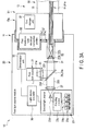
- the first storage unit 57 as illustrated in FIG. 1 and FIG. 3A stores information to the effect that the irradiation module is the first irradiation module 50.
- the first storage unit 57 transmits the information to the determination unit 33 via the first irradiation-side electrical connection portion 55 and light source-side electrical connection portion 37b.
- the first emission unit 63 includes an optical conversion member 63a which is disposed at the other end portion of the first irradiation module 50 and is optically connected to the other end portion of the bundle fiber 61a.
- the optical conversion member 63a includes a lens system which converts the light, which is emitted from the other end portion of the bundle fiber 61a, to illumination light having a desired light distribution and divergence angle, and irradiates the illumination light. In general, since the divergence angle of the light emitted from the end portion of the bundle fiber 61a is small, the optical conversion member 63a increases this divergence angle.
- the second irradiation-side connection portion 71 includes a second irradiation-side optical connection portion 73 which is connected to the light source-side optical connection portion 37a; a second irradiation-side electrical connection portion 75 which is connected to the light source-side electrical connection portion 37b; and a second storage unit 77.
- the position of the second irradiation-side connection portion 71 in the second irradiation module 70 is identical to the position of the first irradiation-side connection portion 51 in the first irradiation module 50.
- the second irradiation-side optical connection portion 73 includes a cover glass 73a on which the light converged by the light focusing member 31 is made incident, when the second irradiation-side optical connection portion 73 is connected to the light source-side optical connection portion 37a; and a light focusing member 73b which is disposed in rear of the cover glass 73a and is optically connected to one end portion of the single optical fiber 81a.
- the cover glass 73a is formed of a light-transmissive material.
- the light focusing member 73b focuses light on the single optical fiber 81a such that the light, which has transmitted through the cover glass 73a, may be made incident on the single optical fiber 81a.
- the diameter of the core portion is several ⁇ m to several-hundred ⁇ m, a positional displacement leads to great optical loss.
- the optical loss is prevented by the light focusing member 73b being disposed also on the irradiation module side.
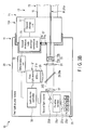
- the second storage unit 77 as illustrated in FIG. 1 and FIG. 3B stores information to the effect that the irradiation module is the second irradiation module 70.
- the second storage unit 77 transmits the information to the light source controller 35 via the second irradiation-side electrical connection portion 75 and light source-side electrical connection portion 37b.
- the second emission unit 83 includes an optical conversion unit 85 which is disposed at the other end portion of the second irradiation module 70 and is optically connected to the other end portion of the single optical fiber 81a.
- the optical conversion unit 85 as illustrated in FIG. 2 includes a wavelength converter 87 which converts, as desired, the wavelength of light which is emitted from the other end portion of the single optical fiber 81a; and a holding member 89 including a first holding hole portion 89a which holds the other end portion of the single optical fiber 81a, and a second holding hole portion 89b which holds the wavelength converter 87.
- the wavelength converter 87 includes a transparent member 87a having, for example, a truncated conical shape; a fluorescent body 87b which is disposed within the transparent member 87a, converts the wavelength of light, and emits fluorescence; and a diffusion member 87c which diffuses the fluorescence emitted from the fluorescent body 87b.
- the transparent member 87a is formed of a member with high transmissivity to a laser beam.
- the fluorescent body 87b is formed of a ceramic of, e.g. YAG:Ce.
- the fluorescent body 87b is excited by an irradiated laser beam, and emits lights with different wavelengths.
- the fluorescent body 87b emits light in all directions.
- part of the light travels back to the optical fiber 81a side, but the light, which travels back, is reflected by the taper-shaped second holding hole portion 89b toward the distal end portion side of the second irradiation module 70.
- the fluorescence emitted from the fluorescent body 87b and the laser beam transmitting through the fluorescent body 87b are diffused by the diffusion member 87c, illuminate a target object, and are utilized as white illumination.
- the optical conversion unit 85 is not limited to the above structure.
- the optical conversion unit 85 has characteristics with a function of converting the peak wavelength, spectrum shape, light distribution angle, light amount, etc., with respect to the optical properties of the light that is incident on the optical conversion unit 85 from the single optical fiber 81a.
- the holding member 89 holds, within the holding member 89, the other end portion of the single optical fiber 81a and the wavelength converter 87 by the first holding hole portion 89a and second holding hole portion 89b, such that the other end portion of the single optical fiber 81a and the wavelength converter 87 are optically coupled in the inside of the holding member 89.
- the holding member 89 functions as, for example, a sleeve.
- the other end portion of the single optical fiber 81a is adhered to an end face portion of the holding member 89 by an adhesive 89c.
- the first holding hole portion 89a has a cylindrical shape
- the second holding hole portion 89b has a taper shape.
- connection between the first light source module 20 and the first irradiation module 50 (bundle fiber scope), and the connection between the first light source module 20 and the second irradiation module 70 (single fiber scope).
- the endoscope light source system 10 includes light guide routes which include the light source, the light source-side connection hole portion 37, the irradiation-side connection portion, the light guide member and the emission unit, and which are optical paths for passage of light.
- the following is defined in the connection between the first light source module 20 and the first irradiation module 50 illustrated in FIG. 3A .
- a light guide route which includes the first light source 21, the light source-side connection hole portion 37, the first irradiation-side connection portion 51, the first light guide member 61 and the first emission unit 63, is defined as a first light guide route 201.
- a light guide route which includes the second light source 23, the light source-side connection hole portion 37, the first irradiation-side connection portion 51, the first light guide member 61 and the first emission unit 63, is defined as a third light guide route 203.
- a light guide route which includes the first light source 21, the second light source 23, the light source-side connection hole portion 37, the first irradiation-side connection portion 51, the first light guide member 61 and the first emission unit 63, is defined as a fourth light guide route 204.
- the following is defined in the connection between the first light source module 20 and the second irradiation module 70 illustrated in FIG. 3B .
- a light guide route which includes the second light source 23, the light source-side connection hole portion 37, the second irradiation-side connection portion 71, the second light guide member 81 and the second emission unit 83, is defined as a second light guide route 202.
- the light source-side connection hole portion 37 is shared and made common to the first irradiation-side connection portion 51 and second irradiation-side connection portion 71, such that the first light guide route 201, the second light guide route 202, the third light guide route 203 and the fourth light guide route 204 can be constituted.
- the first storage unit 57 transmits the information to the determination unit 33 via the first irradiation-side electrical connection portion 55 and light source-side electrical connection portion 37b. This information includes information to the effect that the irradiation module is the first irradiation module 50.
- the determination unit 33 determines that the irradiation module, which is connected to the first light source module 20, is the first irradiation module 50, and transmits the determination result to the light source controller 35. Based on this determination result, the light source controller 35 controls the LED light source 21a and laser light source 23a.
- the first light guide route 201 is used. Specifically, by the control of the light source controller 35, the LED light source 21a is driven, and white LED light is emitted.
- the white LED light irradiates a target object via the first collimation member 25, coupling member 29, light focusing member 31, cover glass 53a, rod lens 53b, first light guide member 61 (bundle fiber 61a) and optical conversion member 63a.
- the white LED light is white light.
- the third light guide route 203 is used. Specifically, by the control of the light source controller 35, the LD in the laser light source 23a, which emits a laser beam with a wavelength of 405 nm, and the LD, which emits a laser beam with a wavelength of 515 nm, are driven, and a laser beam with a wavelength of 405 nm and a laser beam with a wavelength of 515 nm are emitted.
- the laser beam irradiates a target object via the light guide member 23b, coupling member 23c, light guide member 23d, second collimation member 27, coupling member 29, light focusing member 31, cover glass 53a, rod lens 53b, first light guide member 61 (bundle fiber 61a) and optical conversion member 63a.
- the laser beam is special light.
- the target object which is illuminated by the white light or special light, is imaged by an imaging unit (not shown) which is disposed at a distal end portion of the insertion section 19, and is displayed as an observation image on a display unit (not shown) which is connected to the coupling connector 15a.
- a normal optical image which is an observation image in the normal optical observation
- a special optical image which is an observation image in the special optical observation
- the display unit can display, in a superimposed manner, the special optical image, which was obtained by the special light and in which blood vessels are emphasized, upon the normal optical image obtained by the white light.
- the light source controller 35 switches at high speed the driving of the LED light source 21a and the driving of the laser light source 23a, that is, if the first light guide route 201 and third light guide route 203 are switched at high speed, the white light and special light are alternately emitted, and the white light and special light are made incident on the first irradiation module 50 alternately at high speed.
- the normal optical image obtained by the white light and the special optical image obtained by the special light can be acquired during one frame captured by the imaging unit.
- the display unit can display these two observation images on one screen. The above applies similarly to the fourth light guide route.
- the above is controlled, for example, by the light source controller 35.
- the LED light and laser beam are selectively used in accordance with various purposes of use for observation.
- the second storage unit 77 transmits the information to the determination unit 33 via the second irradiation-side electrical connection portion 75 and light source-side electrical connection portion 37b. This information includes information to the effect that the irradiation module is the second irradiation module 70.
- the determination unit 33 determines that the irradiation module, which is connected to the first light source module 20, is the second irradiation module 70, and transmits the determination result to the light source controller 35. Based on this determination result, the light source controller 35 controls the laser light source 23a.
- the second light guide route 202 is used. Specifically, by the control of the light source controller 35, the LD in the laser light source 23a, which emits a laser beam with a wavelength of 405 nm, and the LD, which emits a laser beam with a wavelength of 445 nm, are driven, and a laser beam with a wavelength of 405 nm and a laser beam with a wavelength of 445 nm are emitted.
- the laser beam irradiates a target object via the light guide member 23b, coupling member 23c, light guide member 23d, second collimation member 27, coupling member 29, light focusing member 31, cover glass 73a, light focusing member 73b, single optical fiber 81a and optical conversion unit 85. In the meantime, the laser beams are coupled in the coupling member 23c and converted to white light.
- the first light source module 20, which includes the first light source 21 and second light source 23, is shared and made common to the first irradiation module 50 and second irradiation module 70.
- the light source-side connection hole portion 37 of the first light source module 20 is a common member, which is shared between the first irradiation-side connection portion 51 of the first irradiation module 50, which is connected to the light source-side connection hole portion 37, and the second irradiation-side connection portion 71 of the second irradiation module 70, which is connected to the light source-side connection hole portion 37.
- the first light source module 20 which can reduce time and labor for the connection to various kinds of irradiation modules 50, 70, and the endoscope light source system 10 including this first light source module 20. Furthermore, in this embodiment, since the light source-side connection hole portion 37 of the first light source module 20 is common to irradiation modules 50 and 70 and is disposed at the same position, the time and labor for the connection can be reduced.
- the light source-side connection hole portion 37 is made common to the first irradiation-side connection portion 51 and second irradiation-side connection portion 71, such that the first light guide route 201, second light guide route 202, third light guide route 203 and fourth light guide route 204 can be constituted.
- the first irradiation module 50 and second irradiation module 70 can exhibit performances.
- the characteristics of the first light source 21 which emits scattered light are different from the characteristics of the second light source 23 which emits coherent light such as a laser beam.
- the lamp light is largest, the LED light is second largest, and laser beam is smallest. If the light emission area is large, even if an optical element such as a lens is used, the light beam diameter cannot be reduced to focus on an area smaller than the effective light emission area.
- the bundle fiber 61a with a large cross-sectional area is used for the LED light or lamp light with a large light emission area.
- a laser beam with a very small light emission area can be incident on the single optical fiber with a small cross-sectional area with high efficiency.
- the single optical fiber with a small cross-sectional area is used for the laser beam with a very small light emission area.
- the lamp light is widest
- the LED light is second widest
- laser beam is narrowest.
- the bundle fiber 61a with a large reception angle (NA) is used for the lamp light or LED light.
- the single optical fiber 81a with a small reception angle (NA) is used for the LED light.
- the light guide members 61 and 81 which are used, are different from each other, in accordance with the light sources 21 and 23.
- the first light source module 20 for example, the light source-side connection hole portion 37, which is connected to the first irradiation module 50, is disposed as a separate body from the light source-side connection hole portion 37, which is connected to the second irradiation module 70.
- the first light source module becomes heavier, and the scope needs to be connected by visually distinguishing the light source-side connection hole portion 37. As a result, a load is imposed on the user.
- the light source-side connection hole portion 37 of the first light source module 20 is common to the irradiation modules 50 and 70, and is disposed at the same position.
- the first light source module 20 can have compatibility.
- the lamp light has a largest spectrum width
- the LED light source 21a has a second largest spectrum width
- the laser beam has a smallest spectrum width.
- lamp light or LED light having a broad spectrum shape is suitable.
- a laser beam having a narrow spectrum shape is needed.
- the present embodiment is very effective, in which lamp light or LED light, and a laser beam are simultaneously used, or lamp light or LED light, and a laser beam are quickly switched and used.
- the first light source module 20 can adapt to various purposes of use for observation.
- the user can selectively use the irradiation module 50, 70 in accordance with the purpose of use, and can perform various diagnoses, etc.
- the first light guide member 61 includes the bundle fiber 61a and the second light guide member 81 includes the single optical fiber 81a, such that the effective cross-sectional area of the second light guide member 81 becomes smaller than the light-guide cross-sectional area of the first light guide member 61.
- the first irradiation module 50 functions as a bundle fiber scope
- the second irradiation module 70 functions as a single fiber scope.
- the first, third and fourth light guide routes are formed by the first irradiation module 50, and the second light guide route 202 is formed by the second irradiation module 70, thus being able to adapt to various purposes of use for observation.
- the laser beam is made incident on the single optical fiber 81a by the light focusing member 31 with high efficiency.
- a high optical coupling efficiency can be obtained with reduced power consumption, and with no optical loss.
- the single optical fiber 81a with the thickness of several-hundred ⁇ m substantially the same amount of light as with the bundle fiber 61a with the thickness of several mm can be transmitted to the optical conversion unit 85, and the insertion section 19 can be reduced in thickness.
- the second irradiation module 70 is used, and thereby a large amount of illumination light can be obtained.
- the light source-side connection hole portion 37 positions the first irradiation-side connection portion 51 and second irradiation-side connection portion 71, such that the position of the optical axis of the first irradiation-side connection portion 51 agrees with the position of the optical axis of the second irradiation-side connection portion 71.
- most parts of the structure of the first irradiation module 50 and the structure of the second irradiation module 70 can be made uniform.
- a special optical image can be superimposed on a normal optical image.
- a normal optical image and a special optical image can be displayed on one screen.
- the present embodiment can adapt to various purposes of use for observation.
- first light source 21 and second light source 23 can be used, thus being able to adapt to various purposes of use for observation.
- the optical axis of the LED light agrees with the optical axis of the laser beam.
- the degree of freedom of the position of disposition of the first light source 21 and second light source 23 can be enhanced.
- the coupling member 29 by the coupling member 29, the light beam diameter of the LED light and the light beam diameter of the laser beam become identical to each other. Thereby, when the LED light and laser beam are incident on the first irradiation module 50, the uniformity in incidence efficiency and light intensity can be improved.
- the relative distance between the first light source 21 and first collimation member 25 and the relative distance between the second light source 23 and second collimation member 27 are adjusted as desired.
- the light beam diameter of the first parallel beam and the light beam diameter of the second parallel beam can be made identical to each other.
- the coupling member 29 by the coupling member 29, the light distribution angle of the LED light and the light distribution angle of the laser beam agree with each other. Thereby, when the LED light and laser beam are incident on the first irradiation module 50, the uniformity in incidence efficiency and light intensity can be improved.
- the insertion section 19 would become thicker, the number of members would increase, and the cost would increase. Since the first emission units 63 are different from each other, their light emission points are different from each other. As a result, in a normal optical observation image and a special optical observation image, deviation would occur in formation of shades or in color.
- the LED light or laser beam can be made incident on the first irradiation module 50 or second irradiation module 70 with no waste.
- the determination unit 33 the irradiation module, which is connected, can easily be determined.
- the light source controller 35 by the light source controller 35, light corresponding to a purpose of use for observation can quickly be emitted by connecting the irradiation module to the light source module, for example, at the same time as the irradiation module is connected to the light source module.
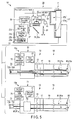
- the light source module includes any one of the first light source module 20 as illustrated in FIG. 1 , a second light source module 100 in which only the first light source 21 is mounted as illustrated in FIG. 4A , and a third light source module 101 in which only the second light source 23 is mounted as illustrated in FIG. 4B .
- the LED light source 21a emits white light.
- the white LED may be replaced with a plurality of LEDs which emit lights of mutually different wavelengths, and these lights may be coupled to produce white light.
- the laser light source 23a may include a plurality of optimal LDs in accordance with purposes of use.
- the purposes of use indicate, for example, fluorescent observation or therapy such as PDT or PDD, oximetry, and pseudo-white observation by an RGB laser.
- the LDs emit lights with mutually different wavelengths or outputs. In particular, by plural LDs of different types being mounted, the light source module can adapt to various purposes of use.
- the coupling member 29 may include, in place of the mirror 29a, a half mirror or an optical system, for instance.
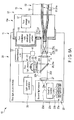
- FIG. 5 Referring to FIG. 5 , FIG. 6A and FIG. 6B , only different points from the first embodiment will be described.
- the first light source 21 includes, in place of the LED light source 21a, a lamp light source 21b such as a Xe lamp or a halogen lamp.
- the lamp light source 21b emits lamp light having very broad spectrum characteristics in a visible light region.
- a clear observation image can be obtained by lamp light than in the case where LED light of the LED light source 21a is used.
- the first collimation member 25 converts the lamp light, which is emitted from the lamp light source 21b, to parallel light.
- the first light source module 20 includes a filter member 39 which is disposed between the first collimation member 25 and mirror 29a and cuts off unnecessary light of the lamp light.
- the filter member 39 includes, for example, a cold filter which cuts off light of an infrared region, which is unnecessary light, or an RGB band-pass filter corresponding to an RGB field-sequential imaging method. Thereby, it is possible to adapt to not only photography by white light, but also to a scope of the RGB field-sequential imaging method.
- the first light source module 20 includes an adjusting member 41 which adjusts, based on the determination result of the determination unit 33, at least one of the light distribution angle, intensity distribution and light beam diameter of the light which is incident on the irradiation-side connection portion 51, 71 from the light source 21, 23 in accordance with a light guide route.
- the adjusting member 41 moves, for example, the light focusing member 31 in the direction of travel of light, and adjusts the position of the light focusing member 31.
- the adjusting member 41 may move the first collimation member 25 or second collimation member 27, and may adjust the position of the first collimation member 25 or the positon of the second collimation member 27.
- the adjusting member 41 may include a movable lens system which is movable based on the determination result, such that the optimal light distribution angle, light intensity distribution or light beam diameter is realized in accordance with the scope.
- the light focusing member 31 can exactly focus light on the irradiation-side optical connection portion 53, 73 in accordance with the irradiation module 50, 70.
- the position of focus can be adjusted in accordance with the irradiation module 50, 70.
- light can exactly be made incident on the light guide member 61, 81 with no waste.
- the light focus is implemented by the length of the irradiation-side optical connection portion 53, 73 being adjusted as desired.
- the first irradiation-side optical connection portion 53 includes a GRIN lens 53c in place of the rod lens 53b.
- the refractive index of a central part of the GRIN lens 53c is higher than the refractive index of a peripheral part around the central part.
- the second irradiation-side optical connection portion 73 includes a GRIN lens 73c in place of the light focusing member 73b.
- the refractive index of a central part of the GRIN lens 73c is higher than the refractive index of a peripheral part around the central part.
- the light guide member 61, 81 is branched into a plurality of parts.
- an end portion of the bundle fiber 61a is branched into two parts.
- the optical fiber is divided with a desired ratio.
- an optical coupler 79 which is a branching member which branches light, is disposed, for example, in the second irradiation-side connection portion 71.
- a plurality of single optical fibers 81a are connected to the optical coupler 79.
Landscapes
- Health & Medical Sciences (AREA)
- Life Sciences & Earth Sciences (AREA)
- Physics & Mathematics (AREA)
- Surgery (AREA)
- Optics & Photonics (AREA)
- Engineering & Computer Science (AREA)
- Animal Behavior & Ethology (AREA)
- Veterinary Medicine (AREA)
- Pathology (AREA)
- Nuclear Medicine, Radiotherapy & Molecular Imaging (AREA)
- Biomedical Technology (AREA)
- Heart & Thoracic Surgery (AREA)
- Medical Informatics (AREA)
- Molecular Biology (AREA)
- Biophysics (AREA)
- General Health & Medical Sciences (AREA)
- Public Health (AREA)
- Radiology & Medical Imaging (AREA)
- Astronomy & Astrophysics (AREA)
- General Physics & Mathematics (AREA)
- Signal Processing (AREA)
- Multimedia (AREA)
- Endoscopes (AREA)
- Instruments For Viewing The Inside Of Hollow Bodies (AREA)
- Non-Portable Lighting Devices Or Systems Thereof (AREA)
- Planar Illumination Modules (AREA)
- Optical Couplings Of Light Guides (AREA)
- Microelectronics & Electronic Packaging (AREA)
Abstract
Description
- The present invention relates to a light source module, and an endoscope light source system including the light source module.
- For example, Patent Literature 1 discloses an example of a light source system in which a plurality of light sources and light guide members corresponding to the respective light sources are mounted. In this light source system, three kinds of light sources, namely a laser light source, a lamp light source and an LED light source, are combined with a single optical fiber for laser light, and a bundle fiber for lamp light and LED light.
- In addition, in this light source system, selective use is implemented in accordance with a purpose of use, such that the lamp light source or LED light source is used for white-light illumination for use in normal optical observation, and the laser light source is used for narrow-band illumination for use in special optical observation.
- Patent Literature 1:
Jpn. Pat. Appln. KOKAI Publication No. 2013-125608 - In the light source system disclosed in Patent Literature 1, two kinds of coupling connectors are used in combination, with respect to a coupling connector which connects a light source module that includes a light source, and an irradiation module that includes a light guide such as a light guide member. Specifically, the light source system includes a single connector which connects the laser light source and the single optical fiber, and a bundle connector which connects the lamp light source or LED light source and the bundle fiber. Only the single connector is used for the irradiation module in which only the single optical fiber is mounted, and only the bundle connector is used for the irradiation module in which only the bundle fiber is mounted. Both the single connector and the bundle connector are used for the irradiation module in which the single optical fiber and bundle fiber are mounted.
- In the above, since the light sources are separate bodies, the light source-side connection portions, to which the single connector and bundle connector are connected, are also separate bodies, and, as a result, a lot of time and labor is taken.
- The present invention has been made in consideration of the above circumstance, and the object of the invention is to provide a light source module which can reduce time and labor for the connection to various kinds of irradiation modules, and an endoscope light source system including this light source module.
- According to one embodiment of the invention, there is provided a light source module including a light source-side connection hole portion to which a irradiation-side connection portion of a irradiation module is mechanically detachably attached, such that illumination light corresponding to a purpose of use is emitted from the irradiation module by a combination of the light source module and the irradiation module. The light source-side connection hole portion is made common to a first irradiation-side connection portion, which is mounted in a first irradiation module, and a second irradiation-side connection portion, which is mounted in a second irradiation module, such that the light source-side connection hole portion is connectable to the first irradiation-side connection portion and the second irradiation-side connection portion.
-
-
FIG. 1 is a schematic view of a first light source module according to a first embodiment of the present invention, and an endoscope light source system including the first light source module. -
FIG. 2 is a view illustrating the structure of a second emission unit. -
FIG. 3A is a view illustrating a state in which the first light source module shown inFIG. 1 is connected to a first irradiation module. -
FIG. 3B is a view illustrating a state in which the first light source module shown inFIG. 1 is connected to a second irradiation module. -
FIG. 4A is a view illustrating the structure of a second light source module. -
FIG. 4B is a view illustrating the structure of a third light source module. -
FIG. 5 is a schematic view of a first light source module according to a second embodiment, and an endoscope light source system including the first light source module. -
FIG. 6A is a view illustrating a state in which the first light source module shown inFIG. 5 is connected to a first irradiation module. -
FIG. 6B is a view illustrating a state in which the first light source module shown inFIG. 5 is connected to a second irradiation module. - Hereinafter, embodiments of the present invention will be described in detail with reference to the accompanying drawings. Incidentally, in some drawings, depiction of some of members is omitted for the purpose of clearer illustration.
- A first embodiment will be described with reference to
FIG. 1 ,FIG. 2 ,FIG. 3A andFIG. 3B . - An endoscope
light source system 10 as illustrated inFIG. 1 includes a light source module, and an irradiation module which can be mechanically detachably attached to the light source module. As illustrated inFIG. 1 , the endoscopelight source system 10 is composed of, for example, one light source module (first light source module 20) and two irradiation modules (first irradiation module 50 and second irradiation module 70). Therespective irradiation modules FIG. 1 ,FIG. 3A andFIG. 3B , thefirst light module 20 and theirradiation module first irradiation module 50 is attached to the firstlight source module 20, thesecond irradiation module 70 is detached from the firstlight source module 20, and such that when thesecond irradiation module 70 is attached to the firstlight source module 20, thefirst irradiation module 50 is detached from the firstlight source module 20. By this combination, illumination light corresponding to a purpose of use is emitted from theirradiation module light source module 20. Furthermore, the firstlight source module 20 is a common member which is shared and made common to thefirst irradiation module 50 andsecond irradiation module 70. - The first
light source module 20 is mounted on, for example, alight source device 11, and theirradiation module endoscope 13 which is detachably attached to thelight source device 11. - Hereinafter, referring to
FIG. 1 ,FIG. 3A andFIG. 3B , a description is given of a concrete structure of the light source module by taking the firstlight source module 20 as an example. - As illustrated in
FIG. 1 ,FIG. 3A andFIG. 3B , in the firstlight source module 20, afirst light source 21, and asecond light source 23 with a light emission area, which is smaller than a light emission area of thefirst light source 21, are mounted. Thefirst light source 21 includes anLED light source 21a which emits LED light that is first light, and thesecond light source 23 includes alaser light source 23a which emits a laser beam that is second light. Thefirst light source 21 andsecond light source 23 are disposed such that the optical axis of the first light emitted from thefirst light source 21 and the optical axis of the second light emitted from thesecond light source 23 cross perpendicular to each other. - Depending on purposes of use, there are many combinations of the
LED light source 21a andlaser light source 23a. Hereinafter, a description is given of, for example, a case in which theLED light source 21a is used for normal optical observation, and thelaser light source 23a is used for special optical observation. In the meantime, the special optical observation refers to, for example, observation for distinguishing a superficial vessel and a deep vessel in a living body. - The LED
light source 21a includes a white LED which emits white LED light. Thelaser light source 23a includes a LD which emits a laser beam with a wavelength of 405 nm, a LD which emits a laser beam with a wavelength of 445 nm, and a LD which emits a laser beam with a wavelength of 515 nm. - The second
light source 23 includes singlelight guide members 23b on which laser beams emitted from thelaser light source 23a are made incident; and acoupling member 23c which couples the laser beams guided by thelight guide members 23b. The secondlight source 23 further includes alight guide member 23d which guides a laser beam coupled by thecoupling member 23c. Onelight guide member 23b is optically connected to one LD. Each of thelight guide members - As illustrated in
FIG. 1 ,FIG. 3A andFIG. 3B , the firstlight source module 20 further includes afirst collimation member 25 including a lens which converts LED light emitted from thefirst light source 21 to a first parallel beam; and asecond collimation member 27 including a lens which converts a laser beam emitted from the secondlight source 23 to a second parallel beam. - The laser beam is incident on the
second collimation beam 27 in the state in which the laser beam has a divergence angle corresponding to a reception angle (NA) of thelight guide member 23d. Thesecond collimation beam 27 converts the laser beam in this state to a parallel beam. - The relative distance between the
first light source 21 andfirst collimation member 25 and the relative distance between the secondlight source 23 andsecond collimation member 27 are adjusted as desired, such that the light beam diameter of the first parallel beam and the light beam diameter of the second parallel beam become identical to each other. - As illustrated in
FIG. 1 ,FIG. 3A andFIG. 3B , the firstlight source module 20 further includes a coupling member 29 which is disposed in front of thefirst collimation member 25 andsecond collimation member 27 in directions of travel of light, and couples the LED light, which is the first parallel beam, and the laser beam which is the second parallel beam. The coupling member 29 couples such that an optical axis of the LED light and an optical axis of the laser beam agree with each other. Thus, the coupling member 29 further includes a mirror 29a which is disposed at an intersection between the LED light and the laser beam, partially reflects, or reflects, the LED light toward a light source-side connection hole portion 37 (to be described later), and transmits through the laser beam toward the light source-sideconnection hole portion 37. The mirror 29a includes, for example, a dichroic mirror. The mirror 29a is disposed, for example, at an angle of 45° to the optical axis of the LED light and the optical axis of the laser beam. In the meantime, when thefirst light source 21 and secondlight source 23 are reversely disposed, use is made of, as the mirror 29a, a mirror which transmits through the LED light toward the light source-sideconnection hole portion 37, and totally reflects the laser beam toward the light source-sideconnection hole portion 37. According to the above, the LED light and laser beam can be coupled by the mirror 29a. - As described above, the light beam diameter of the first parallel beam and the light beam diameter of the second parallel beam are made identical to each other, by the relative distance between the
first light source 21 andfirst collimation member 25 and the relative distance between the secondlight source 23 andsecond collimation member 27. Thus, the coupling member 29 couples the LED light and laser beam such that the light beam diameter of the LED light, which is the first parallel beam, and the light beam diameter of the laser beam, which is the second parallel beam, become identical to each other. The coupling member 29 couples the LED light and laser beam such that the entire light beam of the LED light, which is the first parallel beam, overlaps the entirety of the laser beam, which is the second parallel beam. The coupling member 29 may couple the LED light and laser beam such that the light distribution angle of the LED light and the light distribution angle of the laser beam agree with each other. - As illustrated in
FIG. 1 ,FIG. 3A andFIG. 3B , the firstlight source module 20 further includes alight focusing member 31 which focuses the light coupled by the coupling member 29 toward the light source-sideconnection hole portion 37. Specifically, thelight focusing member 31 focuses the light onto an irradiation-sideoptical connection portion irradiation module optical connection portion 37a of the light source-sideconnection hole portion 37. Thelight focusing member 31 is disposed in front of the coupling member 29 in the direction of travel of light. Thelight focusing member 31 is shared by thefirst light source 21 and secondlight source 23. Thelight focusing member 31 includes, for example, a lens. - As illustrated in
FIG. 1 ,FIG. 3A andFIG. 3B , the firstlight source module 20 further includes adetermination unit 33 which determines theirradiation module determination unit 33 determines whether the irradiation module, which is connected to the firstlight source module 20, is thefirst irradiation module 50 or thesecond irradiation module 70, based on information stored in astorage unit 57, 77 (to be described later) which theirradiation module - As illustrated in
FIG. 1 ,FIG. 3A andFIG. 3B , the firstlight source module 20 further includes alight source controller 35 which controls at least one of thefirst light source 21 and the secondlight source 23, based on a determination result of thedetermination unit 33. - As illustrated in
FIG. 1 ,FIG. 3A andFIG. 3B , the firstlight source module 20 further includes the light source-sideconnection hole portion 37 to/from which acoupling connector 15a that is disposed on auniversal cord 15 of theendoscope 13 is attached/detached, and which functions as a receptacle portion of thelight source device 11. The light source-sideconnection hole portion 37 is shared and made common to a first irradiation-side connection portion 51 and second irradiation-side connection portion 71, such that the light source-sideconnection hole portion 37 is detachably connectable to the first irradiation-side connection portion 51 mounted on thefirst irradiation module 50 and to the second irradiation-side connection portion 71 mounted on thesecond irradiation module 70. For example, the light source-sideconnection hole portion 37 is mechanically detachably attached to the first irradiation-side connection portion 51 and second irradiation-side connection portion 71 in therespective irradiation modules connection hole portion 37 is a common member to the first irradiation-side connection portion 51 and second irradiation-side connection portion 71. Hence, the light source-sideconnection hole portion 37, which is connected to the first irradiation-side connection portion 51, is the same part as the light source-sideconnection hole portion 37 which is connected to the second irradiation-side connection portion 71, and is disposed at the same position as the light source-sideconnection hole portion 37 which is connected to the second irradiation-side connection portion 71. Thus, the light source-sideconnection hole portion 37 positions the first irradiation-side connection portion 51 and second irradiation-side connection portion 71, such that the position of the optical axis of the first irradiation-side connection portion 51 at a time when the light source-sideconnection hole portion 37 is connected to the first irradiation-side connection portion 51 agrees with the position of the optical axis of the second irradiation-side connection portion 71 at a time when the light source-sideconnection hole portion 37 is connected to the second irradiation-side connection portion 71. - As illustrated in
FIG. 1 ,FIG. 3A andFIG. 3B , the light source-sideconnection hole portion 37 includes a light source-sideoptical connection portion 37a which is connected to the irradiation-sideoptical connection portion side connection portion electrical connection portion 37b which is connected to an irradiation-sideelectrical connection portion side connection portion optical connection portion 37a and the irradiation-sideoptical connection portion electrical connection portion 37b and the irradiation-sideelectrical connection portion - The light source-side
optical connection portion 37a is disposed coaxial with, for example, thelight focusing member 31, and is disposed coaxial with a position at which the light focused by thelight focusing member 31 is focused. The light source-sideoptical connection portion 37a includes a through-hole portion through which the irradiation-sideoptical connection portion - The light source-side
electrical connection portion 37b is connected to thedetermination unit 33. - As described above, the irradiation modules include the
first irradiation module 50 andsecond irradiation module 70 as illustrated inFIG. 1 ,FIG. 3A andFIG. 3B . A brief description will be given below of common parts between thefirst irradiation module 50 andsecond irradiation module 70. - The
irradiation module side connection portion connection hole portion 37 and on which light emitted from the light source-sideconnection hole portion 37 is made incident at a time of connection; a light guide member 61, 81 which guides the light that is made incident from the irradiation-side connection portion emission unit 63, 83 which emits to an outside the light guided by the light guide member 61, 81. - Hereinafter, concrete structures of the
first irradiation module 50 andsecond irradiation module 70 of the irradiation modules will be described. - The
first irradiation module 50 functions as a bundle fiber scope. In thefirst irradiation module 50, the first irradiation-side connection portion 51, the first light guide member 61 and the first emission unit 63 are mounted. - The
second irradiation module 70 functions as a single fiber scope. In thesecond irradiation module 70, the second irradiation-side connection portion 71, the second light guide member 81 andsecond emission unit 83 are mounted. - Each of the first irradiation-
side connection portion 51 and second irradiation-side connection portion 71 is disposed in thecoupling connector 15a which is disposed, for example, on theuniversal cord 15 of theendoscope 13. Each of the first light guide member 61 and second light guide member 81 is disposed in the inside of theuniversal cord 15, anoperation section 17 and asoft insertion section 19 of theendoscope 13. Each of the first emission unit 63 andsecond emission unit 83 is disposed a distal end portion of theinsertion section 19. - The
endoscope 13, in which thefirst irradiation module 50 is mounted, is a separate body from theendoscope 13 in which thesecond irradiation module 70 is mounted. - A greatest difference between the first irradiation module 50 (bundle fiber scope) and second irradiation module 70 (single fiber scope) is that their optical functions, for example, are different from each other, and, specifically, the kinds of their light guide members 61 and 81 are different from each other.
- For example, the first light guide member 61 includes a bundle fiber 61a which is formed by bundling a plurality of optical fiber strands, and the second light guide member 18 includes a single optical fiber 81a, such that an effective cross-sectional area of the second light guide member 81 becomes smaller than a light-guide cross-sectional area of the first light guide member 61. The effective cross-sectional area indicates a cross section perpendicular to the center axis of the light guide member 61, 81, and indicates a light emission area.
- In the bundle fiber 61a, the optical fiber strand includes a core portion (not shown) disposed at a central part of the single optical fiber, and a clad portion (not shown) disposed in a manner to cover the core portion. The diameter of the core portion is several µm to several-ten µm. The refractive index of the clad portion is lower than the refractive index of the core portion. Thus, light is reflected by an interface between the core portion and clad portion, confined in the core portion, and guided by the core portion. Thereby, the optical fiber strand confines the light in the inside of the optical fiber strand, and transmits the light to the first emission unit 63 without leaking the light. The diameter of the bundle fiber 61a is, for example, about several mm.
- The single optical fiber 81a includes a core portion (not shown) disposed at a central part of the single optical fiber 81a, and a clad portion (not shown) disposed in a manner to cover the core portion. The diameter of the core portion is several µm to several-hundred µm. The refractive index of the clad portion is lower than the refractive index of the core portion. Thus, light is reflected by an interface between the core portion and clad portion, confined in the core portion, and guided by the core portion. Thereby, the optical fiber 81a confines the light in the inside of the optical fiber 81a, and transmits the light to the
second emission unit 83 without leaking the light. - As illustrated in
FIG. 1 andFIG. 3A , the first irradiation-side connection portion 51 includes a first irradiation-sideoptical connection portion 53 which is connected to the light source-sideoptical connection portion 37a; a first irradiation-sideelectrical connection portion 55 which is connected to the light source-sideelectrical connection portion 37b; and afirst storage unit 57. - As illustrated in
FIG. 1 andFIG. 3A , the first irradiation-sideoptical connection portion 53 includes acover glass 53a on which the light focused by thelight focusing member 31 is made incident, when the first irradiation-sideoptical connection portion 53 is connected to the light source-sideoptical connection portion 37a; and arod lens 53b which is disposed in rear of thecover glass 53a in the direction of travel of light, and is optically connected to one end portion of the bundle fiber 61a. - The
cover glass 53a is formed of a light-transmissive material. - The
rod lens 53b includes a core portion (not shown) disposed at a central part of therod lens 53b, and a clad portion (not shown) disposed in a manner to cover the core portion. The refractive index of the clad portion is lower than the refractive index of the core portion. Thus, light is reflected by an interface between the core portion and clad portion, confined in the core portion, and guided by the core portion. Thereby, therod lens 53b confines the light in the inside of therod lens 53b, and transmits the light to the bundle fiber 61a without leaking the light. The diameter of therod lens 53b is substantially equal to the diameter of the bundle fiber 61a. Therod lens 53b uniformizes the light intensity in the cross section in a direction perpendicular to the optical axis of light. This light indicates the light that is made incident on the first irradiation-sideoptical connection portion 53 from the firstlight source module 20. - In general, the light intensity of a laser beam is strong at a central part of the laser beam, and becomes weaker away from the central part. In this manner, the light intensity of the laser beam is nonuniform. If the laser beam is directly made incident on the bundle fiber 61a in this state, a variance occurs among the amounts of light incident on the respective optical fibers of the bundle fiber 61a. In addition, a deviation occurs in the light intensity of the laser beam emitted from the bundle fiber 61a, and nonuniformity in luminance or nonuniformity in light distribution occurs in illumination light. However, by the
rod lens 53b, the laser beam is repeatedly reflected within therod lens 53b, and the laser beam is incident, with no variance, on the bundle fiber 61a. Thus, the deviation in light intensity of the laser beam is eliminated, and the light intensity becomes uniform. Therefore, nonuniformity in luminance or nonuniformity in light distribution is prevented. - The
first storage unit 57 as illustrated inFIG. 1 andFIG. 3A stores information to the effect that the irradiation module is thefirst irradiation module 50. When the first irradiation-sideelectrical connection portion 55 is connected to the light source-sideelectrical connection portion 37b, thefirst storage unit 57 transmits the information to thedetermination unit 33 via the first irradiation-sideelectrical connection portion 55 and light source-sideelectrical connection portion 37b. - As illustrated in
FIG. 1 andFIG. 3A , the first emission unit 63 includes an optical conversion member 63a which is disposed at the other end portion of thefirst irradiation module 50 and is optically connected to the other end portion of the bundle fiber 61a. The optical conversion member 63a includes a lens system which converts the light, which is emitted from the other end portion of the bundle fiber 61a, to illumination light having a desired light distribution and divergence angle, and irradiates the illumination light. In general, since the divergence angle of the light emitted from the end portion of the bundle fiber 61a is small, the optical conversion member 63a increases this divergence angle. - As illustrated in
FIG. 1 andFIG. 3B , the second irradiation-side connection portion 71 includes a second irradiation-sideoptical connection portion 73 which is connected to the light source-sideoptical connection portion 37a; a second irradiation-sideelectrical connection portion 75 which is connected to the light source-sideelectrical connection portion 37b; and asecond storage unit 77. The position of the second irradiation-side connection portion 71 in thesecond irradiation module 70 is identical to the position of the first irradiation-side connection portion 51 in thefirst irradiation module 50. - As illustrated in
FIG. 1 andFIG. 3B , the second irradiation-sideoptical connection portion 73 includes acover glass 73a on which the light converged by thelight focusing member 31 is made incident, when the second irradiation-sideoptical connection portion 73 is connected to the light source-sideoptical connection portion 37a; and alight focusing member 73b which is disposed in rear of thecover glass 73a and is optically connected to one end portion of the single optical fiber 81a. - The
cover glass 73a is formed of a light-transmissive material. - The
light focusing member 73b focuses light on the single optical fiber 81a such that the light, which has transmitted through thecover glass 73a, may be made incident on the single optical fiber 81a. In the optical fiber 81a, since the diameter of the core portion is several µm to several-hundred µm, a positional displacement leads to great optical loss. The optical loss is prevented by thelight focusing member 73b being disposed also on the irradiation module side. - The
second storage unit 77 as illustrated inFIG. 1 andFIG. 3B stores information to the effect that the irradiation module is thesecond irradiation module 70. When the second irradiation-sideelectrical connection portion 75 is connected to the light source-sideelectrical connection portion 37b, thesecond storage unit 77 transmits the information to thelight source controller 35 via the second irradiation-sideelectrical connection portion 75 and light source-sideelectrical connection portion 37b. - As illustrated in
FIG. 2 , thesecond emission unit 83 includes anoptical conversion unit 85 which is disposed at the other end portion of thesecond irradiation module 70 and is optically connected to the other end portion of the single optical fiber 81a. - The
optical conversion unit 85 as illustrated inFIG. 2 includes awavelength converter 87 which converts, as desired, the wavelength of light which is emitted from the other end portion of the single optical fiber 81a; and a holdingmember 89 including a firstholding hole portion 89a which holds the other end portion of the single optical fiber 81a, and a secondholding hole portion 89b which holds thewavelength converter 87. - The
wavelength converter 87 includes atransparent member 87a having, for example, a truncated conical shape; afluorescent body 87b which is disposed within thetransparent member 87a, converts the wavelength of light, and emits fluorescence; and a diffusion member 87c which diffuses the fluorescence emitted from thefluorescent body 87b. Thetransparent member 87a is formed of a member with high transmissivity to a laser beam. Thefluorescent body 87b is formed of a ceramic of, e.g. YAG:Ce. Thefluorescent body 87b is excited by an irradiated laser beam, and emits lights with different wavelengths. Thefluorescent body 87b emits light in all directions. Thus, part of the light travels back to the optical fiber 81a side, but the light, which travels back, is reflected by the taper-shaped second holdinghole portion 89b toward the distal end portion side of thesecond irradiation module 70. Part of the laser beam, which is irradiated on thefluorescent body 87b, transmits through thefluorescent body 87b. The fluorescence emitted from thefluorescent body 87b and the laser beam transmitting through thefluorescent body 87b are diffused by the diffusion member 87c, illuminate a target object, and are utilized as white illumination. - Here, the
optical conversion unit 85 is not limited to the above structure. Theoptical conversion unit 85 has characteristics with a function of converting the peak wavelength, spectrum shape, light distribution angle, light amount, etc., with respect to the optical properties of the light that is incident on theoptical conversion unit 85 from the single optical fiber 81a. - The holding
member 89 holds, within the holdingmember 89, the other end portion of the single optical fiber 81a and thewavelength converter 87 by the firstholding hole portion 89a and second holdinghole portion 89b, such that the other end portion of the single optical fiber 81a and thewavelength converter 87 are optically coupled in the inside of the holdingmember 89. The holdingmember 89 functions as, for example, a sleeve. The other end portion of the single optical fiber 81a is adhered to an end face portion of the holdingmember 89 by an adhesive 89c. The firstholding hole portion 89a has a cylindrical shape, and the secondholding hole portion 89b has a taper shape. - Hereinafter, a description is given of the connection between the first
light source module 20 and the first irradiation module 50 (bundle fiber scope), and the connection between the firstlight source module 20 and the second irradiation module 70 (single fiber scope). - By the above-described connection, the endoscope
light source system 10 includes light guide routes which include the light source, the light source-sideconnection hole portion 37, the irradiation-side connection portion, the light guide member and the emission unit, and which are optical paths for passage of light. - For the purpose of convenience, the following is defined in the connection between the first
light source module 20 and thefirst irradiation module 50 illustrated inFIG. 3A . - A light guide route, which includes the
first light source 21, the light source-sideconnection hole portion 37, the first irradiation-side connection portion 51, the first light guide member 61 and the first emission unit 63, is defined as a firstlight guide route 201. - A light guide route, which includes the second
light source 23, the light source-sideconnection hole portion 37, the first irradiation-side connection portion 51, the first light guide member 61 and the first emission unit 63, is defined as a thirdlight guide route 203. - A light guide route, which includes the
first light source 21, the secondlight source 23, the light source-sideconnection hole portion 37, the first irradiation-side connection portion 51, the first light guide member 61 and the first emission unit 63, is defined as a fourthlight guide route 204. - For the purpose of convenience, the following is defined in the connection between the first
light source module 20 and thesecond irradiation module 70 illustrated inFIG. 3B . - A light guide route, which includes the second
light source 23, the light source-sideconnection hole portion 37, the second irradiation-side connection portion 71, the second light guide member 81 and thesecond emission unit 83, is defined as a secondlight guide route 202. - In addition, the light source-side
connection hole portion 37 is shared and made common to the first irradiation-side connection portion 51 and second irradiation-side connection portion 71, such that the firstlight guide route 201, the secondlight guide route 202, the thirdlight guide route 203 and the fourthlight guide route 204 can be constituted. - As illustrated in
FIG. 3A , if the first irradiation-side connection portion 51 is inserted in the light source-sideconnection hole portion 37, the light source-sideoptical connection portion 37a is connected to the first irradiation-sideoptical connection portion 53, and the light source-sideelectrical connection portion 37b is connected to the first irradiation-sideelectrical connection portion 55. These connections are implemented at the same time. At the same time, thefirst storage unit 57 transmits the information to thedetermination unit 33 via the first irradiation-sideelectrical connection portion 55 and light source-sideelectrical connection portion 37b. This information includes information to the effect that the irradiation module is thefirst irradiation module 50. Based on this information, thedetermination unit 33 determines that the irradiation module, which is connected to the firstlight source module 20, is thefirst irradiation module 50, and transmits the determination result to thelight source controller 35. Based on this determination result, thelight source controller 35 controls theLED light source 21a andlaser light source 23a. - In normal optical observation, the first
light guide route 201 is used. Specifically, by the control of thelight source controller 35, the LEDlight source 21a is driven, and white LED light is emitted. The white LED light irradiates a target object via thefirst collimation member 25, coupling member 29,light focusing member 31,cover glass 53a,rod lens 53b, first light guide member 61 (bundle fiber 61a) and optical conversion member 63a. The white LED light is white light. - In special optical observation, the third
light guide route 203 is used. Specifically, by the control of thelight source controller 35, the LD in thelaser light source 23a, which emits a laser beam with a wavelength of 405 nm, and the LD, which emits a laser beam with a wavelength of 515 nm, are driven, and a laser beam with a wavelength of 405 nm and a laser beam with a wavelength of 515 nm are emitted. The laser beam irradiates a target object via thelight guide member 23b,coupling member 23c,light guide member 23d,second collimation member 27, coupling member 29,light focusing member 31,cover glass 53a,rod lens 53b, first light guide member 61 (bundle fiber 61a) and optical conversion member 63a. The laser beam is special light. - The target object, which is illuminated by the white light or special light, is imaged by an imaging unit (not shown) which is disposed at a distal end portion of the
insertion section 19, and is displayed as an observation image on a display unit (not shown) which is connected to thecoupling connector 15a. - In the meantime, in the above, for example, if the
LED light source 21a andlaser light source 23a are driven individually and independently, the normal optical observation and special optical observation are individually implemented. In addition, a normal optical image, which is an observation image in the normal optical observation, is displayed on the display unit, and a special optical image, which is an observation image in the special optical observation, is displayed on the display unit. - For example, if the
LED light source 21a andlaser light source 23a are simultaneously driven, the white light and special light are simultaneously made incident on thefirst irradiation module 50 in the fourth light guide route. In this manner, the white light and special light may be mixed and used. Thereby, the display unit can display, in a superimposed manner, the special optical image, which was obtained by the special light and in which blood vessels are emphasized, upon the normal optical image obtained by the white light. - If the
light source controller 35 switches at high speed the driving of the LEDlight source 21a and the driving of thelaser light source 23a, that is, if the firstlight guide route 201 and thirdlight guide route 203 are switched at high speed, the white light and special light are alternately emitted, and the white light and special light are made incident on thefirst irradiation module 50 alternately at high speed. Thereby, the normal optical image obtained by the white light and the special optical image obtained by the special light can be acquired during one frame captured by the imaging unit. In addition, the display unit can display these two observation images on one screen. The above applies similarly to the fourth light guide route. - The above is controlled, for example, by the
light source controller 35. In this manner, the LED light and laser beam are selectively used in accordance with various purposes of use for observation. - In this manner, in this connection state, one of the following is selected:
- the first
light guide route 201 along which, with only theLED light source 21a being driven, the LED light is guided from the LEDlight source 21a to the optical conversion member 63a via the bundle fiber 61a, etc.; - the third
light guide route 203 along which, with only thelaser light source 23a being driven, the laser beam is guided from thelaser light source 23a to the optical conversion member 63a via the bundle fiber 61a, etc.; and - the fourth
light guide route 204 along which, with theLED light source 21a andlaser light source 23a being driven, the LED light and the laser beam are guided from the LEDlight source 21a andlaser light source 23a to the optical conversion member 63a via the bundle fiber 61a, etc. - As illustrated in
FIG. 3B , if the second irradiation-side connection portion 71 is inserted in the light source-sideconnection hole portion 37, the light source-sideoptical connection portion 37a is connected to the second irradiation-sideoptical connection portion 73, and the light source-sideelectrical connection portion 37b is connected to the second irradiation-sideelectrical connection portion 75. These connections are implemented at the same time. At the same time, thesecond storage unit 77 transmits the information to thedetermination unit 33 via the second irradiation-sideelectrical connection portion 75 and light source-sideelectrical connection portion 37b. This information includes information to the effect that the irradiation module is thesecond irradiation module 70. Based on this information, thedetermination unit 33 determines that the irradiation module, which is connected to the firstlight source module 20, is thesecond irradiation module 70, and transmits the determination result to thelight source controller 35. Based on this determination result, thelight source controller 35 controls thelaser light source 23a. - In this case, the second
light guide route 202 is used. Specifically, by the control of thelight source controller 35, the LD in thelaser light source 23a, which emits a laser beam with a wavelength of 405 nm, and the LD, which emits a laser beam with a wavelength of 445 nm, are driven, and a laser beam with a wavelength of 405 nm and a laser beam with a wavelength of 445 nm are emitted. The laser beam irradiates a target object via thelight guide member 23b,coupling member 23c,light guide member 23d,second collimation member 27, coupling member 29,light focusing member 31,cover glass 73a,light focusing member 73b, single optical fiber 81a andoptical conversion unit 85. In the meantime, the laser beams are coupled in thecoupling member 23c and converted to white light. - Incidentally, in this connection state, it is possible that only the
LED light source 21 is driven and LED light is guided to theoptical conversion unit 85 by the single optical fiber 81a. However, when light with a large light emission point, such as LED light, is incident on a small light guide such as the single optical fiber 81a, light loss increases, and there is concern that a sufficient amount of light does not reach the optical conversion member 63a. Thus, the merit of using this structure is small. - Thus, in this connection state, only the
laser light source 23a is driven, and the secondlight guide route 202 is formed, along which the laser beam is guided from the secondlight source 23 to theoptical conversion unit 85 via the single optical fiber 81a, etc. - As described above, in the present embodiment, the first
light source module 20, which includes thefirst light source 21 and secondlight source 23, is shared and made common to thefirst irradiation module 50 andsecond irradiation module 70. In addition, the light source-sideconnection hole portion 37 of the firstlight source module 20 is a common member, which is shared between the first irradiation-side connection portion 51 of thefirst irradiation module 50, which is connected to the light source-sideconnection hole portion 37, and the second irradiation-side connection portion 71 of thesecond irradiation module 70, which is connected to the light source-sideconnection hole portion 37. Therefore, in the present embodiment, it is possible to provide the firstlight source module 20 which can reduce time and labor for the connection to various kinds ofirradiation modules light source system 10 including this firstlight source module 20. Furthermore, in this embodiment, since the light source-sideconnection hole portion 37 of the firstlight source module 20 is common toirradiation modules - In the present embodiment, the light source-side
connection hole portion 37 is made common to the first irradiation-side connection portion 51 and second irradiation-side connection portion 71, such that the firstlight guide route 201, secondlight guide route 202, thirdlight guide route 203 and fourthlight guide route 204 can be constituted. Thus, in this embodiment, even if thefirst irradiation module 50 andsecond irradiation module 70 have mutually different optical functions, thefirst irradiation module 50 andsecond irradiation module 70 can exhibit performances. - In the meantime, in general, for the light sources having mutually different optical characteristics, such as the
first light source 21 and secondlight source 23, if use is made of the light source-sideconnection hole portions 37, irradiation-side connection portions - Specifically, the characteristics of the
first light source 21 which emits scattered light, such as LED light or lamp light, are different from the characteristics of the secondlight source 23 which emits coherent light such as a laser beam. - To begin with, as regards the light emission area, the lamp light is largest, the LED light is second largest, and laser beam is smallest. If the light emission area is large, even if an optical element such as a lens is used, the light beam diameter cannot be reduced to focus on an area smaller than the effective light emission area.
- In other words, it is difficult for LED light or lamp light with a large light emission area to be efficiently made incident on the single optical fiber 81a with a small cross-sectional area. Necessarily, the bundle fiber 61a with a large cross-sectional area is used for the LED light or lamp light with a large light emission area.
- By contrast, a laser beam with a very small light emission area can be incident on the single optical fiber with a small cross-sectional area with high efficiency. Thus, the single optical fiber with a small cross-sectional area is used for the laser beam with a very small light emission area.
- As regards the divergence angle of light, the lamp light is widest, the LED light is second widest, and laser beam is narrowest. Thus, the bundle fiber 61a with a large reception angle (NA) is used for the lamp light or LED light. The single optical fiber 81a with a small reception angle (NA) is used for the LED light.
- As described above, the light guide members 61 and 81, which are used, are different from each other, in accordance with the
light sources light source module 20, for example, the light source-sideconnection hole portion 37, which is connected to thefirst irradiation module 50, is disposed as a separate body from the light source-sideconnection hole portion 37, which is connected to thesecond irradiation module 70. Thus, the first light source module becomes heavier, and the scope needs to be connected by visually distinguishing the light source-sideconnection hole portion 37. As a result, a load is imposed on the user. - However, in the present embodiment, as described above, the light source-side
connection hole portion 37 of the firstlight source module 20 is common to theirradiation modules light source module 20 can have compatibility. There is no need to provide the same number of light source-sideconnection hole portions 37 as the number ofirradiation modules light source module 20 can be reduced in size, and the cost of the firstlight source module 20 can be reduced. - As regards the spectrum shape, the lamp light has a largest spectrum width, the LED
light source 21a has a second largest spectrum width, and the laser beam has a smallest spectrum width. By these lights being combined, the degree of freedom of the spectrum shape of illumination light, which is usable for diagnosis, etc., can be remarkably enhanced. - Specifically, in normal optical observation, lamp light or LED light having a broad spectrum shape is suitable. However, in special optical observation using only a specific wavelength, a laser beam having a narrow spectrum shape is needed. Thus, as described above, the present embodiment is very effective, in which lamp light or LED light, and a laser beam are simultaneously used, or lamp light or LED light, and a laser beam are quickly switched and used.
- From this viewpoint, by various kinds of
light sources light source module 20, the firstlight source module 20 can adapt to various purposes of use for observation. By preparing one firstlight source module 20, the user can selectively use theirradiation module - In the present embodiment, the first light guide member 61 includes the bundle fiber 61a and the second light guide member 81 includes the single optical fiber 81a, such that the effective cross-sectional area of the second light guide member 81 becomes smaller than the light-guide cross-sectional area of the first light guide member 61. Thus, the
first irradiation module 50 functions as a bundle fiber scope, and thesecond irradiation module 70 functions as a single fiber scope. - Thereby, in the present embodiment, the first, third and fourth light guide routes are formed by the
first irradiation module 50, and the secondlight guide route 202 is formed by thesecond irradiation module 70, thus being able to adapt to various purposes of use for observation. - When the
second irradiation module 70 is used, the laser beam is made incident on the single optical fiber 81a by thelight focusing member 31 with high efficiency. Thus, in thesecond irradiation module 70, a high optical coupling efficiency can be obtained with reduced power consumption, and with no optical loss. By the single optical fiber 81a with the thickness of several-hundred µm, substantially the same amount of light as with the bundle fiber 61a with the thickness of several mm can be transmitted to theoptical conversion unit 85, and theinsertion section 19 can be reduced in thickness. In the case where the insertion section 91 is thin, thesecond irradiation module 70 is used, and thereby a large amount of illumination light can be obtained. - In the present embodiment, the light source-side
connection hole portion 37 positions the first irradiation-side connection portion 51 and second irradiation-side connection portion 71, such that the position of the optical axis of the first irradiation-side connection portion 51 agrees with the position of the optical axis of the second irradiation-side connection portion 71. Thus, in this embodiment, most parts of the structure of thefirst irradiation module 50 and the structure of thesecond irradiation module 70 can be made uniform. - In the present embodiment, if the white light and special light are simultaneously made incident on the
first irradiation module 50, a special optical image can be superimposed on a normal optical image. - In this embodiment, if the white light and special light are alternately made incident on the
first irradiation module 50 at high speed, a normal optical image and a special optical image can be displayed on one screen. - In this manner, the present embodiment can adapt to various purposes of use for observation.
- In the present embodiment, by the coupling member 29, various kinds of first
light source 21 and secondlight source 23 can be used, thus being able to adapt to various purposes of use for observation. - In the present embodiment, by the coupling member 29, the optical axis of the LED light agrees with the optical axis of the laser beam. Thereby, when the LED light and laser beam are incident on the
first irradiation module 50, the uniformity in incidence efficiency and light intensity can be improved. - In the present embodiment, by the mirror 29a, the degree of freedom of the position of disposition of the
first light source 21 and secondlight source 23 can be enhanced. - In this embodiment, by the coupling member 29, the light beam diameter of the LED light and the light beam diameter of the laser beam become identical to each other. Thereby, when the LED light and laser beam are incident on the
first irradiation module 50, the uniformity in incidence efficiency and light intensity can be improved. - In the present embodiment, the relative distance between the
first light source 21 andfirst collimation member 25 and the relative distance between the secondlight source 23 andsecond collimation member 27 are adjusted as desired. Thereby, in this embodiment, the light beam diameter of the first parallel beam and the light beam diameter of the second parallel beam can be made identical to each other. Thereby, when the LED light and laser beam are incident on thefirst irradiation module 50, the uniformity in incidence efficiency and light intensity can be improved. - In the present embodiment, by the coupling member 29, the light distribution angle of the LED light and the light distribution angle of the laser beam agree with each other. Thereby, when the LED light and laser beam are incident on the
first irradiation module 50, the uniformity in incidence efficiency and light intensity can be improved. - By the above, in the normal optical observation and special optical observation, the occurrence of displacement can be prevented.
- For example, in the
first irradiation module 50, if the bundle fiber 61a for a laser beam is a separate body from the bundle fiber 61a for LED light, and if the first emission unit 63 for a laser beam is a separately body from the first emission unit 63 for LED light, theinsertion section 19 would become thicker, the number of members would increase, and the cost would increase. Since the first emission units 63 are different from each other, their light emission points are different from each other. As a result, in a normal optical observation image and a special optical observation image, deviation would occur in formation of shades or in color. However, in the present embodiment, even if the position of thefirst light source 21 and the position of the secondlight source 23 are different from each other, since the first light guide member 61 and first emission unit 63 are made common in thefirst irradiation module 50, the above can be solved. - In the present embodiment, by the
light focusing member 31, the LED light or laser beam can be made incident on thefirst irradiation module 50 orsecond irradiation module 70 with no waste. - In this embodiment, by the
determination unit 33, the irradiation module, which is connected, can easily be determined. - In the present embodiment, by the
light source controller 35, light corresponding to a purpose of use for observation can quickly be emitted by connecting the irradiation module to the light source module, for example, at the same time as the irradiation module is connected to the light source module. - It should suffice if the light source module includes any one of the first
light source module 20 as illustrated inFIG. 1 , a secondlight source module 100 in which only thefirst light source 21 is mounted as illustrated inFIG. 4A , and a thirdlight source module 101 in which only the secondlight source 23 is mounted as illustrated inFIG. 4B . - It should suffice if the
LED light source 21a emits white light. The white LED may be replaced with a plurality of LEDs which emit lights of mutually different wavelengths, and these lights may be coupled to produce white light. - The
laser light source 23a may include a plurality of optimal LDs in accordance with purposes of use. The purposes of use indicate, for example, fluorescent observation or therapy such as PDT or PDD, oximetry, and pseudo-white observation by an RGB laser. The LDs emit lights with mutually different wavelengths or outputs. In particular, by plural LDs of different types being mounted, the light source module can adapt to various purposes of use. - The coupling member 29 may include, in place of the mirror 29a, a half mirror or an optical system, for instance.
- Referring to
FIG. 5 ,FIG. 6A andFIG. 6B , only different points from the first embodiment will be described. - As illustrated in
FIG. 5 , in the firstlight source module 20, thefirst light source 21 includes, in place of the LEDlight source 21a, alamp light source 21b such as a Xe lamp or a halogen lamp. Thelamp light source 21b emits lamp light having very broad spectrum characteristics in a visible light region. Thus, in the present embodiment, in normal optical observation, a clear observation image can be obtained by lamp light than in the case where LED light of the LEDlight source 21a is used. - The
first collimation member 25 converts the lamp light, which is emitted from thelamp light source 21b, to parallel light. - The first
light source module 20 includes afilter member 39 which is disposed between thefirst collimation member 25 and mirror 29a and cuts off unnecessary light of the lamp light. Thefilter member 39 includes, for example, a cold filter which cuts off light of an infrared region, which is unnecessary light, or an RGB band-pass filter corresponding to an RGB field-sequential imaging method. Thereby, it is possible to adapt to not only photography by white light, but also to a scope of the RGB field-sequential imaging method. - The first
light source module 20 includes an adjustingmember 41 which adjusts, based on the determination result of thedetermination unit 33, at least one of the light distribution angle, intensity distribution and light beam diameter of the light which is incident on the irradiation-side connection portion light source member 41 moves, for example, thelight focusing member 31 in the direction of travel of light, and adjusts the position of thelight focusing member 31. In the meantime, the adjustingmember 41 may move thefirst collimation member 25 orsecond collimation member 27, and may adjust the position of thefirst collimation member 25 or the positon of thesecond collimation member 27. The adjustingmember 41 may include a movable lens system which is movable based on the determination result, such that the optimal light distribution angle, light intensity distribution or light beam diameter is realized in accordance with the scope. - By the above, for example, the
light focusing member 31 can exactly focus light on the irradiation-sideoptical connection portion irradiation module light focusing member 31, the position of focus can be adjusted in accordance with theirradiation module - In the meantime, the light focus is implemented by the length of the irradiation-side
optical connection portion - The first irradiation-side
optical connection portion 53 includes aGRIN lens 53c in place of therod lens 53b. The refractive index of a central part of theGRIN lens 53c is higher than the refractive index of a peripheral part around the central part. - The second irradiation-side
optical connection portion 73 includes aGRIN lens 73c in place of thelight focusing member 73b. The refractive index of a central part of theGRIN lens 73c is higher than the refractive index of a peripheral part around the central part. - The light guide member 61, 81 is branched into a plurality of parts.
- In the
first irradiation module 50, an end portion of the bundle fiber 61a is branched into two parts. In this case, the optical fiber is divided with a desired ratio. - In the
second irradiation module 70, anoptical coupler 79, which is a branching member which branches light, is disposed, for example, in the second irradiation-side connection portion 71. A plurality of single optical fibers 81a are connected to theoptical coupler 79. - By the above, light is emitted from a plurality of locations at the end portion of the
irradiation module - The present invention is not limited directly to the above-described embodiments. At the stage of practicing the invention, the structural elements may be modified and embodied without departing from the spirit of the invention. Further, various inventions maybe made by suitably combining a plurality of structural elements disclosed in the embodiments.
Claims (22)
- A light source module including a light source-side connection hole portion to which an irradiation-side connection portion of an irradiation module is mechanically detachably attached, such that illumination light corresponding to a purpose of use is emitted from the irradiation module by a combination of the light source module and the irradiation module,
wherein the light source-side connection hole portion is made common to a first irradiation-side connection portion, which is mounted in a first irradiation module, and a second irradiation-side connection portion, which is mounted in a second irradiation module, such that the light source-side connection hole portion is connectable to the first irradiation-side connection portion and the second irradiation-side connection portion. - The light source module according to Claim 1, wherein the light source module further includes at least one of a first light source and a second light source which emit mutually different lights,
the first irradiation module includes the first irradiation-side connection portion which is connected to the light source-side connection hole portion and on which the light emitted from the light source-side connection hole portion is made incident at a time of the connection, a first light guide member configured to guide the light made incident from the first irradiation-side connection portion, and a first emission unit configured to emit to an outside the light guided by the first light guide member,
the second irradiation module includes the second irradiation-side connection portion which is connected to the light source-side connection hole portion and on which the light emitted from the light source-side connection hole portion is made incident at a time of the connection, a second light guide member configured to guide the light made incident from the second irradiation-side connection portion, and a second emission unit configured to emit to the outside the light guided by the second light guide member,
a light guide route, which is an optical path for passage of the light, and which includes the first light source, the light source-side connection hole portion, the first irradiation-side connection portion, the first light guide member and the first emission unit, is defined as a first light guide route,
the light guide route, which includes the second light source, the light source-side connection hole portion, the second irradiation-side connection portion, the second light guide member and the second emission unit, is defined as a second light guide route,
the light guide route, which includes the second light source, the light source-side connection hole portion, the first irradiation-side connection portion, the first light guide member and the first emission unit, is defined as a third light guide route, and
the light source-side connection hole portion is made common to the first irradiation-side connection portion and the second irradiation-side connection portion, such that the first light guide route, the second light guide route and the third light guide route are capable of being constituted. - The light source module according to Claim 2 , wherein the light source-side connection hole portion is configured to position the first irradiation-side connection portion and the second irradiation-side connection portion, such that a position of an optical axis of the first irradiation-side connection portion at a time when the light source-side connection hole portion is connected to the first irradiation-side connection portion agrees with a position of an optical axis of the second irradiation-side connection portion at a time when the light source-side connection hole portion is connected to the second irradiation-side connection portion.
- The light source module according to Claim 3, wherein the second light source has a light emission area which is smaller than a light emission area of the first light source.
- The light source module according to Claim 4, wherein the first light source includes an LED light source.
- The light source module according to Claim 4, wherein the first light source includes a lamp light source.
- The light source module according to Claim 4, wherein the second light source includes a laser light source.
- The light source module according to Claim 4, wherein the light source module further includes an adjusting member configured to adjust, in accordance with the light guide route, at least one of a light distribution angle, an intensity distribution and a light beam diameter of the light which is incident on the irradiation-side connection portion from the light source module.
- The light source module according to Claim 4, wherein the light source module includes the first light source and the second light source, and
the light guide route, which is defined as a fourth light guide route and includes the first light source, the second light source, the light source-side connection hole portion, the first irradiation-side connection portion, the first light guide member and the first emission unit, is formed when the light source module is connected to the first irradiation module. - The light source module according to Claim 9, wherein in the fourth light guide route, first light emitted from the first light source and second light emitted from the second light source are capable of being simultaneously made incident on the first irradiation module.
- The light source module according to Claim 9, Wherein in the fourth light guide route, first light emitted from the first light source and second light emitted from the second light source are capable of being made incident on the first irradiation module alternately at high speed.
- The light source module according to Claim 10, further comprising a coupling member configured to couple the first light and the second light.
- The light source module according to Claim 12, wherein the coupling member is configured to couple such that an optical axis of the first light and an optical axis of the second light agree with each other.
- The light source module according to Claim 13, wherein the first light source and the second light source are disposed such that the optical axis of the first light and the optical axis of the second light cross perpendicular to each other, and
the coupling member includes a mirror disposed at a crossing part, and configured to reflect the first light and transmit through the second light, or configured to reflect the second light and transmit through the first light. - The light source module according to Claim 12, wherein the coupling member is configured to couple the first light and the second light such that a light beam diameter of the first light and a light beam diameter of the second light become identical to each other.
- The light source module according to Claim 15, further including a first collimation member configured to convert the first light emitted from the first light source to first parallel light, and a second collimation member configured to convert the second light emitted from the second light source to second parallel light, and
a relative distance between the first light source and the first collimation member and a relative distance between the second light source and the second collimation member are adjusted as desired, such that a light beam diameter of the first parallel light and a light beam diameter of the second parallel light become identical to each other. - The light source module according to Claim 12, wherein the coupling member is configured to couple the first light and the second light such that a light distribution angle of the first light and a light distribution angle of the second light agree with each other.
- The light source module according to Claim 17, further including a light focusing member configured to focus light, which is coupled by the coupling member, toward the light source-side connection hole portion.
- The light source module according to Claim 2, further including a determination unit configured to determine the irradiation module which is connected to the light source module.
- The light source module according to Claim 19, further including a light source controller configured to control at least one of the first light source and the second light source, based on a determination result of the determination unit.
- An endoscope light source system configured such that illumination light corresponding to a purpose of use is emitted by a combination of the light source module according to Claim 2 and the first irradiation module or the second irradiation module, which is mechanically detachably attached to the light source module,
wherein the first light guide member includes a bundle fiber which is formed by bundling a plurality of optical fiber strands, and the second light guide member includes a single optical fiber, such that an effective cross-sectional area of the second light guide member becomes less than a light-guide cross-sectional area of the first light guide member. - The endoscope light source system according to Claim 21, wherein a position of the first irradiation-side connection portion in the first irradiation module is identical to a position of the second irradiation-side connection portion in the second irradiation module.
Applications Claiming Priority (2)
| Application Number | Priority Date | Filing Date | Title |
|---|---|---|---|
| JP2014010727A JP6442141B2 (en) | 2014-01-23 | 2014-01-23 | Light source system for endoscope having light source module and light source module |
| PCT/JP2015/051214 WO2015111541A1 (en) | 2014-01-23 | 2015-01-19 | Light source module and endoscope light source system |
Publications (2)
| Publication Number | Publication Date |
|---|---|
| EP3097845A1 true EP3097845A1 (en) | 2016-11-30 |
| EP3097845A4 EP3097845A4 (en) | 2017-11-15 |
Family
ID=53681345
Family Applications (1)
| Application Number | Title | Priority Date | Filing Date |
|---|---|---|---|
| EP15740283.5A Withdrawn EP3097845A4 (en) | 2014-01-23 | 2015-01-19 | Light source module and endoscope light source system |
Country Status (5)
| Country | Link |
|---|---|
| US (1) | US10548466B2 (en) |
| EP (1) | EP3097845A4 (en) |
| JP (1) | JP6442141B2 (en) |
| CN (1) | CN106413519B (en) |
| WO (1) | WO2015111541A1 (en) |
Cited By (2)
| Publication number | Priority date | Publication date | Assignee | Title |
|---|---|---|---|---|
| EP3831273A1 (en) * | 2019-12-04 | 2021-06-09 | Schott Ag | Endoscope, disposable endoscope system and light source for endoscope |
| US11510553B2 (en) | 2018-03-29 | 2022-11-29 | Schott Ag | Light guide or image guide components for disposable endoscopes |
Families Citing this family (8)
| Publication number | Priority date | Publication date | Assignee | Title |
|---|---|---|---|---|
| AU2017387098B2 (en) * | 2016-12-27 | 2022-12-15 | DePuy Synthes Products, Inc. | Systems, methods, and devices for providing illumination in an endoscopic imaging environment |
| KR101969893B1 (en) * | 2017-05-12 | 2019-04-17 | 주식회사 바이오프리즘 | Light device for fluorescence molecular imaging endoscopy |
| CN110785112B (en) * | 2017-06-28 | 2022-06-03 | 奥林巴斯株式会社 | Light source system, endoscope system, and light source control method |
| WO2019138492A1 (en) * | 2018-01-11 | 2019-07-18 | オリンパス株式会社 | Light source device |
| JP7174918B2 (en) * | 2018-08-06 | 2022-11-18 | パナソニックIpマネジメント株式会社 | lighting equipment |
| US11617541B2 (en) | 2019-06-20 | 2023-04-04 | Cilag Gmbh International | Optical fiber waveguide in an endoscopic system for fluorescence imaging |
| US12461299B2 (en) | 2023-11-02 | 2025-11-04 | Orbotech Ltd. | LED and laser diode combined illumination system |
| WO2025094009A1 (en) * | 2023-11-02 | 2025-05-08 | Orbotech Ltd. | Led and laser diode combined illumination system |
Family Cites Families (17)
| Publication number | Priority date | Publication date | Assignee | Title |
|---|---|---|---|---|
| JPH0470710A (en) * | 1990-07-11 | 1992-03-05 | Olympus Optical Co Ltd | Endoscope device |
| US5749830A (en) * | 1993-12-03 | 1998-05-12 | Olympus Optical Co., Ltd. | Fluorescent endoscope apparatus |
| JP3070405B2 (en) * | 1994-08-18 | 2000-07-31 | 富士写真光機株式会社 | Endoscope light guide connector |
| JP3872852B2 (en) | 1996-02-26 | 2007-01-24 | オリンパス株式会社 | Endoscope TV observation system, light source unit used for endoscope TV observation system, and small light source unit for endoscope |
| JP3574591B2 (en) * | 1998-05-01 | 2004-10-06 | ペンタックス株式会社 | Electronic endoscope device for fluorescence diagnosis |
| US6371908B1 (en) * | 1998-05-01 | 2002-04-16 | Asahi Kogaku Kogyo Kabushiki Kaisha | Video endoscopic apparatus for fluorescent diagnosis |
| JP2000035544A (en) * | 1998-07-16 | 2000-02-02 | Asahi Optical Co Ltd | Light guide connector connection part of endoscope device |
| JP2002112962A (en) * | 2000-10-12 | 2002-04-16 | Asahi Optical Co Ltd | Electronic endoscope device |
| JP2003164417A (en) * | 2001-12-04 | 2003-06-10 | Pentax Corp | Electronic endoscope |
| JP2006181061A (en) * | 2004-12-27 | 2006-07-13 | Pentax Corp | Endoscope system |
| JP2006204341A (en) * | 2005-01-25 | 2006-08-10 | Pentax Corp | Light source device |
| JP2009072213A (en) * | 2007-09-18 | 2009-04-09 | Hoya Corp | Endoscope light source unit and endoscope system |
| JP2010042153A (en) * | 2008-08-13 | 2010-02-25 | Fujifilm Corp | Illumination device and endoscope using this |
| JP2010081957A (en) * | 2008-09-29 | 2010-04-15 | Olympus Corp | Light source device |
| CN101485558B (en) * | 2009-02-27 | 2011-03-23 | 浙江工商大学 | Single-optical fiber multiphoton fluorescence scanning endoscope |
| JP2012010962A (en) * | 2010-06-30 | 2012-01-19 | Fujifilm Corp | Light source device for excitation light, and electronic endoscope system |
| JP5926943B2 (en) | 2011-12-13 | 2016-05-25 | オリンパス株式会社 | Light source system having a plurality of light guide routes |
-
2014
- 2014-01-23 JP JP2014010727A patent/JP6442141B2/en active Active
-
2015
- 2015-01-19 EP EP15740283.5A patent/EP3097845A4/en not_active Withdrawn
- 2015-01-19 WO PCT/JP2015/051214 patent/WO2015111541A1/en not_active Ceased
- 2015-01-19 CN CN201580005256.4A patent/CN106413519B/en active Active
-
2016
- 2016-07-21 US US15/215,717 patent/US10548466B2/en active Active
Cited By (4)
| Publication number | Priority date | Publication date | Assignee | Title |
|---|---|---|---|---|
| US11510553B2 (en) | 2018-03-29 | 2022-11-29 | Schott Ag | Light guide or image guide components for disposable endoscopes |
| EP3831273A1 (en) * | 2019-12-04 | 2021-06-09 | Schott Ag | Endoscope, disposable endoscope system and light source for endoscope |
| US11633090B2 (en) | 2019-12-04 | 2023-04-25 | Schott Ag | Endoscope, disposable endoscope system and light source for endoscope |
| EP4437932A3 (en) * | 2019-12-04 | 2024-12-25 | Schott Ag | Light source for endoscope |
Also Published As
| Publication number | Publication date |
|---|---|
| CN106413519A (en) | 2017-02-15 |
| US10548466B2 (en) | 2020-02-04 |
| CN106413519B (en) | 2019-11-05 |
| US20160324408A1 (en) | 2016-11-10 |
| JP6442141B2 (en) | 2018-12-19 |
| JP2015138712A (en) | 2015-07-30 |
| WO2015111541A1 (en) | 2015-07-30 |
| EP3097845A4 (en) | 2017-11-15 |
Similar Documents
| Publication | Publication Date | Title |
|---|---|---|
| EP3097845A1 (en) | Light source module and endoscope light source system | |
| JP6463903B2 (en) | Endoscope system | |
| JP6314041B2 (en) | Endoscope light source device | |
| US20080310181A1 (en) | Brightness with reduced optical losses | |
| CN103988014B (en) | There is the light-source system in multiple guide-lighting path | |
| EP2343006A1 (en) | Medical apparatus and endoscope apparatus | |
| EP2965683A1 (en) | Subject observation system and method | |
| EP2124703A1 (en) | Illumination for endoscope | |
| US20120053420A1 (en) | Endoscopic light guide and endoscope having the same | |
| JP2013090706A (en) | Light source device | |
| CN106308731A (en) | Endoscopic multi-spectrum excited imaging system | |
| EP3838110A1 (en) | Medical system, medical light source device and method for medical light source device | |
| US10598850B2 (en) | Lighting unit | |
| WO2019021388A1 (en) | Endoscope system | |
| JP2011050667A (en) | Optical scan type endoscope | |
| JP5145119B2 (en) | Endoscope light source device | |
| US20190269309A1 (en) | Electronic scope and electronic endoscope system | |
| EP4413914A1 (en) | Beam shaping lens, beam shaping element, light source device for endoscope, and endoscope | |
| US9897757B2 (en) | Fluorescence excitation illumination fiber | |
| JP2006158789A (en) | Endoscope | |
| CN114206197B (en) | Optical device, wireless endoscope, and endoscope system | |
| JP2021096998A (en) | Light source module | |
| JP2011206567A (en) | Endoscope system | |
| CN120753600A (en) | Multi-wavelength optical fiber imaging device and system |
Legal Events
| Date | Code | Title | Description |
|---|---|---|---|
| PUAI | Public reference made under article 153(3) epc to a published international application that has entered the european phase |
Free format text: ORIGINAL CODE: 0009012 |
|
| 17P | Request for examination filed |
Effective date: 20160816 |
|
| AK | Designated contracting states |
Kind code of ref document: A1 Designated state(s): AL AT BE BG CH CY CZ DE DK EE ES FI FR GB GR HR HU IE IS IT LI LT LU LV MC MK MT NL NO PL PT RO RS SE SI SK SM TR |
|
| AX | Request for extension of the european patent |
Extension state: BA ME |
|
| RAP1 | Party data changed (applicant data changed or rights of an application transferred) |
Owner name: OLYMPUS CORPORATION |
|
| DAX | Request for extension of the european patent (deleted) | ||
| A4 | Supplementary search report drawn up and despatched |
Effective date: 20171018 |
|
| RIC1 | Information provided on ipc code assigned before grant |
Ipc: G02B 23/24 20060101ALI20171011BHEP Ipc: A61B 1/002 20060101ALN20171011BHEP Ipc: A61B 1/00 20060101ALI20171011BHEP Ipc: G02B 23/26 20060101ALI20171011BHEP Ipc: H04N 5/225 20060101ALI20171011BHEP Ipc: F21V 7/22 20060101ALI20171011BHEP Ipc: F21S 2/00 20160101ALI20171011BHEP Ipc: F21V 8/00 20060101ALI20171011BHEP Ipc: A61B 1/06 20060101AFI20171011BHEP Ipc: A61B 1/07 20060101ALI20171011BHEP |
|
| STAA | Information on the status of an ep patent application or granted ep patent |
Free format text: STATUS: THE APPLICATION IS DEEMED TO BE WITHDRAWN |
|
| 18D | Application deemed to be withdrawn |
Effective date: 20180518 |