JP3574591B2 - Electronic endoscope device for fluorescence diagnosis - Google Patents
Electronic endoscope device for fluorescence diagnosis Download PDFInfo
- Publication number
- JP3574591B2 JP3574591B2 JP11339699A JP11339699A JP3574591B2 JP 3574591 B2 JP3574591 B2 JP 3574591B2 JP 11339699 A JP11339699 A JP 11339699A JP 11339699 A JP11339699 A JP 11339699A JP 3574591 B2 JP3574591 B2 JP 3574591B2
- Authority
- JP
- Japan
- Prior art keywords
- image
- fluorescence
- electronic endoscope
- normal observation
- image signal
- Prior art date
- Legal status (The legal status is an assumption and is not a legal conclusion. Google has not performed a legal analysis and makes no representation as to the accuracy of the status listed.)
- Expired - Fee Related
Links
- 238000003745 diagnosis Methods 0.000 title claims description 34
- 238000005286 illumination Methods 0.000 claims description 36
- 230000005284 excitation Effects 0.000 claims description 24
- 238000003384 imaging method Methods 0.000 claims description 13
- 238000001514 detection method Methods 0.000 claims description 6
- 238000001429 visible spectrum Methods 0.000 claims 1
- 230000015654 memory Effects 0.000 description 77
- 206010028980 Neoplasm Diseases 0.000 description 27
- 230000003287 optical effect Effects 0.000 description 23
- 230000002159 abnormal effect Effects 0.000 description 12
- 238000003780 insertion Methods 0.000 description 9
- 230000037431 insertion Effects 0.000 description 9
- 238000010586 diagram Methods 0.000 description 8
- 238000000034 method Methods 0.000 description 8
- 230000000694 effects Effects 0.000 description 2
- 230000001678 irradiating effect Effects 0.000 description 2
- 230000003321 amplification Effects 0.000 description 1
- 238000005452 bending Methods 0.000 description 1
- 201000011510 cancer Diseases 0.000 description 1
- 238000006243 chemical reaction Methods 0.000 description 1
- 239000000835 fiber Substances 0.000 description 1
- 238000002073 fluorescence micrograph Methods 0.000 description 1
- 230000006870 function Effects 0.000 description 1
- 239000004973 liquid crystal related substance Substances 0.000 description 1
- 239000011159 matrix material Substances 0.000 description 1
- 238000003199 nucleic acid amplification method Methods 0.000 description 1
- 210000003437 trachea Anatomy 0.000 description 1
Images


Landscapes
- Instruments For Viewing The Inside Of Hollow Bodies (AREA)
- Endoscopes (AREA)
Description
【0001】
【発明が属する技術分野】
本発明は、生体から発せられる自家蛍光に基づいて体腔内を撮像して、生体が正常であるか異常であるかの診断に供される画像データを出力する蛍光診断用電子内視鏡装置に、関する。
【0002】
【従来の技術】
生体に対して特定波長の励起光を照射すると、生体から蛍光が発せられることが知られている(この蛍光は「自家蛍光」と言われる)。さらに、自家蛍光の緑光領域の強度は生体の異常部位(腫瘍,癌)の方が正常部位よりも低いので、画像として表されると、異常部位が正常部位よりも暗く表示されることも、知られている。
【0003】
このような知識をベースに、世界に先駆けて、東京医科大学の加藤治文教授より、生体の自家蛍光を撮像し、生体が正常であるか異常であるかの診断に供される自家蛍光画像を表示する蛍光診断用の電子内視鏡装置が発案され、この発案に基づいて、本件出願人が開発を推し進め、その結果として、生まれた一例が、特開平9−70384号において開示されたものである。
【0004】
この公報に開示された蛍光診断用電子内視鏡装置では、自家蛍光が非常に微弱な光であることが考慮され、電子内視鏡の先端部における対物光学系と撮像素子との間に、自家蛍光を増幅するイメージインテンシファイアが設けられている。従って、この蛍光診断用電子内視鏡装置によると、イメージインテンシファイアによって増幅された自家蛍光の像が撮像素子によって撮像されるので、明るい自家蛍光画像を得ることができる。
【0005】
【発明が解決しようとする課題】
しかしながら、このように電子内視鏡の先端部にイメージインテンシファイアが組み込まれると、この先端部の外径が大きくなってしまう。この先端部は患者の体腔内に挿入される部位であるので、この先端部が太くなり過ぎると、患者に負担が掛かる問題がある。また、イメージインテンシファイアは比較的高価であるので、イメージインテンシファイアを電子内視鏡の先端部に組み込むと、蛍光診断用電子内視鏡装置全体のコストが上昇してしまう問題もある。
【0006】
本発明の課題は、イメージインテンシファイアを用いなくても適正な蛍光診断用画像を得ることができる蛍光診断用電子内視鏡装置を、提供することである。
【0007】
【課題を解決するための手段】
本発明は、上記課題を解決するために、以下の構成を採用した。
【0008】
即ち、請求項1記載の発明は、可視帯域の照明光及び紫外帯域の励起光とを切り替えて生体に照射する照明装置を有するとともに、可視帯域の照明光を照射された前記生体の通常観察画像及び前記励起光を前記生体に照射することによって生じる前記生体の自家蛍光の画像を夫々撮像する撮像装置と、前記通常観察画像から第1の閾値より高い輝度領域を抽出し、前記自家蛍光画像から第2の閾値より低い輝度領域を抽出し、前記通常観察画像から抽出された領域のうち、自家蛍光画像から抽出された領域にも含まれる領域を特定領域として検出する検出部と、前記特定領域を示す画像信号を出力する表示制御装置とを、備えた蛍光診断用電子内視鏡装置である。
【0009】
このように構成されると、検出部が特定領域を抽出し、表示制御装置がこの特定領域を示す画像信号を出力するので、CRTや液晶ディスプレイ等の表示装置上でこの特定領域の形状及び位置を示す画像が表示され得る。従って、検出部が抽出する特定領域の輝度範囲を生体の異常部位から発せられる自家蛍光の輝度が属する範囲に設定すれば、異常部位が特定領域として表示される。このため、イメージインテンシファイアを有していなくても、適正な蛍光診断用の画像を蛍光観察用電子内視鏡装置の利用者(医師等)に提供でき、利用者が適正に自家蛍光に基づく診断を行うことができる。
【0010】
ここに、検出部及び表示制御装置は、例えば、CPU(中央処理装置)のプログラム実行による機能として構成でき、また、LSIやASIC等でも構成できる。
【0013】
また、請求項2記載の発明は、請求項1の表示制御装置が、前記特定領域のみが所定の色で示された蛍光観察画像を表示するための画像信号を出力することで、特定したものである。このように構成されると、被写体となる生体に異常部位があれば、蛍光診断用画像中において、その異常部位が特定領域として所定の色で表示される。このため、装置利用者が容易に異常部位か否かの診断を行うことができる。
【0014】
また、請求項3記載の発明は、請求項1の表示制御装置が、前記通常観察画像のうち前記特定領域のみを単色で示すとともに前記特定領域以外をカラーで示す蛍光観察画像を表示するための画像信号を出力することで、特定したものである。蛍光観察画像は、その全体がモノクロで表示されても良いし、特定領域以外が疑似カラーで表示されても良い。但し、特定領域のみが所定色で表示されるとともに特定領域以外がカラー表示されるように構成すれば、診断がより容易になる。
【0015】
また、請求項4記載の発明は、請求項3の撮像装置が、前記照明装置によって赤,緑,青の各照明光を順番に前記生体に照射しつつ、各照明光が照射された時の前記生体の通常観察画像を夫々撮像し、上記表示制御装置が、前記各照明光が照射された時の前記生体の通常観察画像に基づいてカラー画像を合成するとともに、前記自家蛍光画像から前記特定領域のみを抽出した特定領域画像を生成し、前記カラー画像上に前記特定領域画像をスーパーインポーズしてなる蛍光観察画像を表示するための画像信号を出力することで、特定したものである。
【0016】
また、請求項5記載の発明は、請求項4の表示制御装置が、前記カラー画像と前記蛍光観察画像とを同時に表示するための画像信号を出力することで、特定したものである。このように構成されると、利用者が二つの画像を対比観察することができるので、生体の正常/異常の診断が容易に行われ得る。
【0017】
また、請求項6記載の発明は、請求項1の表示制御装置が、前記通常観察画像を動画として表示するための画像信号を出力することで、特定したものである。
【0018】
また、請求項7記載の発明は、請求項6において、操作者によって操作され、前記通常観察画像のみを表示するための画像信号と前記通常観察画像及び前記蛍光診断用画像を同時に表示するための画像信号とを前記表示制御装置に対して切り替えさせるための切換信号を生じるスイッチをさらに備えたことで、特定したものである。
【0019】
【発明の実施の形態】
以下、図面を参照して本発明の実施の形態を説明する。
〔電子内視鏡装置の構成〕
図1は、本実施形態による蛍光観察用電子内視鏡装置(以下、単に「電子内視鏡装置」という)10の概略構成図である。図1において、電子内視鏡装置10は、電子内視鏡11と、電子内視鏡11に接続された光源装置12及びビデオプロセッサ13と、ビデオプロセッサ13に接続されたパーソナルコンピュータ(PC)14及びモニタ15とから、構成されている。以下、これらの各装置の説明を、個別に行う。
【0020】
電子内視鏡11は、図1では挿入部16のみ図示されているが、実際には、この挿入部の先端近傍に設けられた湾曲部を湾曲操作するためのダイアルや各種の操作スイッチが設けられた操作部,光源装置12に接続されるライトガイド可撓管等、各種の部品から構成されている。図1に図示された挿入部16は、被写体としての生体の体腔内に挿入されるパーツであり、この挿入部16の先端には、軸方向に沿って少なくとも2本の貫通孔が開けられた硬質部材からなる先端部(図示略)が、固定されている。
【0021】
これら二つの貫通孔の挿入部16先端側の開口には、夫々、対物光学系18及び配光レンズ21が填め込まれている。この対物光学系18は、被写体の像を形成する結像光学系であり、その後方(基端側)には、順番に、カットオフフィルタ19及び固体撮像素子(CCD)17が固定されている。このカットオフフィルタ19は、自家蛍光を励起するための励起光(紫外線)が被写体に照射された際に、この被写体表面で反射して対物光学系18を透過した励起光を遮光する。CCD17は、対物光学系18による被写体の結像位置に配置され、信号線17aを介してビデオプロセッサ13に接続されている。このCCD17が対物光学系18による被写体像を撮像して得た画像信号は、この信号線17aを介してビデオプロセッサ13に入力され、このビデオプロセッサ13によって処理される。
【0022】
一方、配光レンズ21の基端側には、電子内視鏡11の図示せぬライトガイド可撓管及び操作部を通って挿入部16に引き通されたライトガイドファイババンドル(以下、「ライトガイド」という)20の出射端面が配置されている。このライトガイド20の入射端面は、光源装置12の内部に配置されるので、ライトガイド20は、光源装置12から供給される照明光を挿入部16の先端まで伝達する。このライトガイド20の出射端面から出射された照明光は、配光レンズ21によって広げられ、対物光学系18及びCCD17による撮像範囲を照明する。
【0023】
光源装置12は、ライトガイド20に照明光を供給する装置であり、その内部には、白色光源22が設けられている。白色光源22は、通常観察用の照明光としての白色光を出射するランプと、このランプから出射された白色光を収束するリフレクタとから、構成されている。上記したライトガイド20の入射端面は、白色光源22のリフレクタの光軸上において白色光が収束される位置に配置されているので、白色光源22から出射された照明光が効率よくこのライトガイド20に入射する。
【0024】
ライトガイド20と白色光源22との間における照明光の光路途中には、RGB回転フィルタ23が配置されている。RGB回転フィルタ23は、等角度の扇状の平面形状を有するとともに互いの間に遮光部を挟んで配置されたR(赤),G(緑)及びB(青)の三色のカラーフィルタを有しており、図示せぬモータによって等速度で回転する。従って、RGB回転フィルタ23に組み込まれた各カラーフィルタは、R,G,Bの順で、白色光源22から発せられた照明光の光路に繰り返し挿入される。これによって、R光,G光及びB光の各照明光が、ライトガイド20の入射端面に繰り返し入射され、ライトガイド20を通って挿入部16の先端から出射され、配光レンズ21を介して被写体を照明する。そして、各照明光によって照明された被写体の対物光学系18による像(即ち、被写体像)をCCD17が撮像し、ビデオプロセッサ13がカラー画像として合成する。このようにして、いわゆるRGB面順次方式による撮像が行われる。
【0025】
さらに、光源装置12の内部には、自家蛍光の励起光としての紫外線を出射するランプとこのランプから出射された励起光を収束するリフレクタとから構成される光源(UV光源)24,このUV光源24から発せられた励起光をライトガイド20の入射端面に導く第1ミラー25及び第2ミラー26が、設けられている。この第1ミラー25は、通常観察時には、UV光源24から発せられる励起光の光路外に配置され、蛍光診断時には、励起光の光路内に挿入され、励起光を第2ミラー26へ向けて反射する。第2ミラー26は、通常観察時には、白色光源22から出射される照明光の光路外に配置され、蛍光診断時には、RGB回転フィルタ23とライトガイド20との間における照明光の光路内に挿入されて、白色光源22からの照明光を遮光するとともに、第1ミラー25によって反射された励起光をライトガイド20の入射端面へ向けて反射する。以上の構成により、通常観察時にはRGB回転フィルタ23を経た照明光(R光,G光,B光)がライトガイド20の入射端面に入射し、蛍光診断時にはUV光源24から出射された励起光がライトガイド20の入射端面に入射する。
【0026】
さらに、光源装置12は、光源制御部27を有している。この光源制御部27は、例えばPC14からの指示に従って、ライトガイド20に入射される照明光や励起光の光量を調整するとともに、白色光源22,RGB回転フィルタ23,第1ミラー25及び第2ミラー26の動作を制御する。また、光源制御部27は、RGBの各カラーフィルタが白色光源22から出射された照明光の光路を通過するタイミングを示す信号(同期信号)を、PC14に与える。
【0027】
ビデオプロセッサ13は、信号線17aに接続されたスイッチSWを有している。スイッチSWは、二つの出力端子T1,T2とこれら各出力端子T1,T2に対して選択的に接触し得るスイッチ片に導通した入力端子とからなるスイッチであるが、実際にはこのような構成のスイッチと等価な電子回路として構成される。このスイッチSWのスイッチ片は、通常観察時には出力端子T1と接触し、蛍光診断時には出力端子T2と接触する。スイッチSWの出力端子T1は、アナログ/デジタル変換器(A/Dコンバータ)28の入力端子に接続されている。
【0028】
このA/Dコンバータ28は、通常観察時におけるCCD17の出力信号(画像信号)をアナログ・ディジタル変換して、その出力端子に出力する。このA/Dコンバータ28の出力端子は、Rメモリ29,Gメモリ30及びBメモリ31の夫々の入力端子に接続されている。
【0029】
Rメモリ29は、被写体にR光が照射された際にCCD17から出力された画像信号(「R画像信号」と称する)を格納する。また、Gメモリ30は、被写体にG光が照射された際にCCD17から出力された画像信号(「G画像信号」と称する)を格納する。また、Bメモリ31は、被写体にB光が照射された際にCCD17から出力された画像信号(「B画像信号」と称する)を格納する。
【0030】
一方、スイッチSWの出力端子T2は、アンプ32の入力端子に接続されている。このアンプ32は、蛍光診断時にCCD17から出力された画像信号(「F画像信号」と称する)を増幅して、その出力端子に出力する。このアンプ32の出力端子は、A/Dコンバータ33の入力端子に接続されている。このA/Dコンバータ33は、アンプ32によって増幅されたF画像信号をアナログ・ディジタル変換して、その出力端子に出力する。このA/Dコンバータ33の出力端子は、Fメモリ34の入力端子に接続されている。このFメモリ34は、A/Dコンバータ33から出力されるF画像信号を格納する。
【0031】
これらRメモリ29,Gメモリ30,Bメモリ31及びFメモリ34の各出力端子は、スキャンコンバータ36に接続されている。このスキャンコンバータ36の各出力端子は、PC14に接続されている。このスキャンコンバータ36は、PC14から入力される同期信号に従って、Rメモリ29,Gメモリ30,及び、Bメモリ31に格納されたRGBの各画像信号を読み出し、同期をとってPC14へ向けて出力する。同様に、スキャンコンバータ36は、PC14から入力される同期信号に従って、Fメモリ34からF画像信号を読み出し、PC14へ向けて出力する。
【0032】
なお、ビデオプロセッサ13は、マイクロコンピュータ(MIC)35を有している。このMIC35は、PC14に接続されるとともに、ビデオプロセッサ13の外部に設けられた外部スイッチ36aに接続されている。また、MIC35は、スイッチSW,アンプ32,Rメモリ29,Gメモリ30,Bメモリ31及びFメモリ34の各制御端子にも接続されている。このMIC35は、PC14からの制御命令に従って、スイッチSWのスイッチ片を出力端子T1及び出力端子T2の何れか一方に対して選択的に接触させる。また、MIC35は、PC14からの制御命令に従って、アンプ32の増幅率を調整する。また、MIC35は、PC14から入力される同期信号に従って、各A/Dコンバータ28,33からの出力信号を、Rメモリ,Gメモリ,Bメモリ,Fメモリのうち、該当するメモリに格納する。
【0033】
さらに、ビデオプロセッサ13は、PC14に接続されたディジタル/アナログ変換器(D/Aコンバータ)37を有している。D/Aコンバータ37は、PC14から出力されるRGB画像信号をディジタル・アナログ変換し、モニタ15に入力する。これによって、モニタ15には、アナログRGB画像信号に基づく被写体の画像が表示される。
【0034】
PC14は、ビデオプロセッサ13から出力された各画像信号に対して更に画像処理を施すコンピュータである。このPC14は、図2のブロックに詳細に図示されているように、光源装置12の光源制御部27及びビデオプロセッサ13のMIC35に接続されたCPU(中央処理装置)38と、CPU38に接続されたビデオキャプチャー39,メモリ部40及びVRAM(ビデオRAM)41とから、構成されている。
【0035】
このビデオキャプチャー39は、ビデオプロセッサ13のスキャンコンバータ36から出力されるRGBの各画像信号,或いはF画像信号を一旦蓄積し、CPU38からの指示に従ってメモリ部40に入力する。
【0036】
このメモリ部40は、ビデオキャプチャー39から出力されたRGBの各画像信号を格納するメモリM1(mem_RGB)の領域と、ビデオキャプチャー39から出力されたF画像信号を格納するメモリMF(mem_FL)の領域と、蛍光診断用画像の作成処理に使用されるメモリM2(mem_RGB2)の領域とに区別されたRAM(Random Access Memory)であり、CPU38による処理に際して使用される。
【0037】
VRAM41は、CPU38から出力されたモニタ15に表示されるべき内容を示すデータ(RGB画像信号)を保持し、CPU38からの指示に従って、保持しているRGB画像信号をD/Aコンバータ37へ出力する。
【0038】
CPU38は、図示せぬROM(Read Only Memory)に格納された制御プログラムを実行することによって、光源制御部27,MIC35,ビデオキャプチャー39,メモリ部40及びVRAM41の動作を制御する。
【0039】
以下、上記した構成を有する各装置からなる電子内視鏡装置の動作例を、PC14のCPU38による処理に沿って説明する。
【0040】
図3は、CPU38による処理(メインルーチン)を示すフローチャートであり、図4は、図3のS8にて実行される蛍光診断用画像生成処理のサブルーチンを示すフローチャートである。図3に示された処理は、光源装置12,ビデオプロセッサ13,及びPC14の主電源が夫々投入されることをトリガに、スタートする。
【0041】
スタート後、最初に、CPU38は、光源装置12を通常観察状態にて動作させる旨の制御命令を、光源制御部27に対して与える(S1)。すると、光源装置12の光源制御部27は、UV光源24から出射された励起光の光路外に第1ミラー25を待避させるとともに、白色光源22から出射された照明光の光路外に第2ミラー26を待避させる(図1の破線参照)。続いて、光源制御部27は、白色光源22及びUV光源24を点灯させるとともに、RGB回転フィルタ23を回転させる。そして、光源制御部27は、RGB回転フィルタ23の同期信号をCPU38に与える。CPU38は、この同期信号をMIC35及びスキャンコンバータ36に与える(S2)。また、CPU38が、スイッチSWのスイッチ片を出力端子T1に接触させる旨の制御命令を、MIC35に与える(S3)。これによって、MIC35が、スイッチSWのスイッチ片と出力端子T1とを接触させる。
【0042】
これまでのS1からS3までの制御が実行されることにより、白色光源22から白色照明光が出射され、この白色照明光は、RGB回転フィルタ23を通過することによってR光,G光,B光の各照明光となり、順番に、ライトガイド20に入射される。そして、各色の照明光は、ライトガイド20を通じて電子内視鏡11の先端部まで伝達され、ライトガイド20の出射端面から出射され、配光レンズ21によって拡散されつつ、被写体(即ち、体腔内壁)を順番に照明する。
【0043】
被写体が各照明光によって順番に照射されると、被写体からの反射光が対物光学系18によってCCD17の撮像面に被写体の像を結び、この被写体像がCCD17によって撮像される。すると、CCD17から、各照明光に基づく画像信号(R画像信号,G画像信号,B画像信号)が、順次出力される。各画像信号は、信号線17a,スイッチSWを経てA/Dコンバータ28に入力され、A/Dコンバータ28によってアナログ・ディジタル変換され、各メモリ29,30,31の入力端子に入力される。この時、CPU38からの同期信号に基づいてMIC35が各メモリ29,30,31の制御端子に対して順番に制御信号を入力する。
【0044】
この制御信号が入力されると、各メモリ29,30,31は、その時点でA/Dコンバータ28から出力されている画像信号を取り込み、次の制御信号が入力されるまでその画像信号を保持し続ける。従って、R画像信号はRメモリ29に格納され、G画像信号はGメモリ30に格納され、B画像信号はBメモリ31に格納される。このようにして、Rメモリ29,Gメモリ30及びBメモリ31には、夫々、RGBの各画像信号が1画面分記憶される。すると、スキャンコンバータ36が、各メモリ29〜31からRGBの各画像信号を読み出し、同期をとってPC14へ向けて出力する。このようにしてPC14に送信されたRGBの各画像信号は、PC14のビデオキャプチャー39に蓄積される。
【0045】
すると、CPU38は、ビデオキャプチャー39に蓄積されたRGBの画像信号を、順次、メモリ部40のメモリM1に書き込む(S4)。その結果、メモリM1上では、夫々8ビットの輝度値であるR画像信号,G画像信号及びB画像信号から各画素が構成される24ビットRGB画像信号(通常観察画像のデータ)が、合成される。
【0046】
続いて、CPU38は、メモリM1に格納された通常観察画像のデータ(RGB画像信号)を読み出してVRAM41に書き込む(S5)。続いて、CPU38は、VRAM41に格納されたRGB画像信号をD/Aコンバータ37へ向けて出力させる(S6)。すると、D/Aコンバータ37は、VRAM41から出力されたRGB画像信号をディジタル・アナログ変換し、モニタ15に供給する。これによって、図5に示すように、モニタ15の左側の表示領域には、照明光によって照明された際における被写体(生体)の画像,即ち、通常観察画像が、カラー表示される。本実施形態では、VRAM41からは、例えば1/30秒毎に1画面分のRGB画像信号が出力され、この画像信号に基づく画像がモニタ15に表示されるようになっている。このため、モニタ15の左側の表示領域には、通常観察画像が動画で表示される。
【0047】
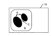
以上の動作が通常観察時における動作である。図5には、被写体の通常観察画像として、気管の管空部Aと、気管の管壁部Bとからなる通常観察画像が示されている。但し、実際には管壁部Bには腫瘍部位Cが含まれているが、通常観察画像の輝度分布は図6に示す通りであるので、この腫瘍部位Cは、通常観察画像では正常部分と殆ど見分けがつかない。
【0048】
次に、蛍光診断時における電子内視鏡装置10の動作を説明する。
【0049】
外部スイッチ36aが投入されると、ビデオプロセッサ13のMIC35は、この投入によって生じる信号(ON信号)を検出し、その旨をPC14(CPU38)に通知する。一方、CPU38は、上記S1〜S6の処理が終了する毎に、MIC35からON信号を検出した旨の通知があったかを判定し(S7)、なかった場合には処理をS1に戻し、あった場合にはS8において、蛍光診断用画像作成処理を実行する。
【0050】
図4は、このS8において実行される蛍光診断用画像作成処理サブルーチンを示すフローチャートである。このサブルーチンに入ると、CPU38は、最初に、最新に得られた通常観察画像のデータ(RGB画像信号)を、メモリM1に格納させる(S101)。ここでは、メモリM1には、図5に示したのとほぼ同じ通常観察画像のデータが、格納されたものとする。
【0051】
続いて、CPU38は、光源装置12を蛍光観察状態にて動作させる旨の制御命令を、光源制御部27に与える(S102)。すると、光源装置12の光源制御部27が、UV光源24からの励起光の光路内に第1ミラー25を挿入するとともに、この第1ミラー25によって反射された励起光をライトガイド20の入射端面に向けて反射させる位置に第2ミラー26を移動させる。続いて、CPU38は、スイッチSWのスイッチ片を出力端子T2に接触させるとともにアンプ32を起動させる旨の制御命令を、MIC35に与える(S103)。これによって、MIC35は、スイッチSWのスイッチ片を出力端子T2と接触させるとともに、アンプ32の制御端子に制御信号を与える。
【0052】
S102及びS103の制御が実行されることにより、UV光源24から出射された励起光が、第1ミラー25及び第2ミラー26によって反射され、ライトガイド20に入射される。そして、この励起光は、ライトガイド20を通じて電子内視鏡11の先端部まで伝達されて、ライトガイド20の出射端面から出射され、配光レンズ21によって拡散されつつ、被写体に照射される。すると、被写体たる気管の生体組織から自家蛍光が発せられる。このとき、生体組織の正常部位から発する自家蛍光中の緑光帯域成分の強度は腫瘍部位Cから発する自家蛍光中の緑光帯域成分の強度よりも高い。
【0053】
この自家蛍光及び励起光の反射光を含む被写体からの光は、対物光学系18に入射し、カットオフフィルタ19を透過する。このカットオフフィルタ19は紫外帯域の光をカットするので、自家蛍光成分のみがカットオフフィルタ19を透過し、CCD17の撮像面に被写体の像を結ぶ。これによって、CCD17は、励起光が照射された際における被写体(生体)の画像,即ち、自家蛍光画像を、撮像する。このとき、生体の正常部位からの自家蛍光の強度は異常部位からの自家蛍光の強度よりも高いので、図9に示されるように、CCD17の各画素のうち正常部位の像を撮像した画素の受光量は、腫瘍部位Cの像を撮像した画素の受光量よりも大きくなる。そして、CCD17は、これら各画素の受光量に対応する画像信号(F画像信号)を出力する。
【0054】
その後、F画像信号は、信号線17a及びスイッチSWを通ってアンプ32に伝達され、このアンプ32によって増幅され、A/Dコンバータ33にてアナログ・デジタル変換され、Fメモリ34に格納される。このようにして1画面分のF画像信号がFメモリ34に記憶されると、スキャンコンバータ36が、Fメモリ34内部のF画像信号をPC14へ向けて出力する。これによって、F画像信号がビデオキャプチャー39に蓄積される。
【0055】
すると、CPU38は、ビデオキャプチャー39に蓄積されたF画像信号(自家蛍光画像のデータ)を、メモリMFに格納する(S104)。このようにして、ほぼ同一の撮像範囲について、メモリM1には通常観察画像のデータ(RGB画像信号)が格納され、メモリMFには自家蛍光画像のデータ(F画像信号)が格納される。
【0056】
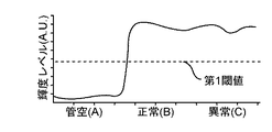
続いて、CPU38は、この時点でメモリM1に格納されているRGB画像信号(通常観察画像のデータ)における同じ画素についてのR画像信号の輝度値,G画像信号の輝度値及びB画像信号の輝度値に対して所定のマトリックス演算を施すことによって、その画素全体の輝度値(8ビットで表される二進値)を算出する(RGB−YCC変換)。CPU38は、このようにして全画素について夫々算出された輝度値(Y信号)をメモリM2に書き込む(S105)。その結果メモリM2に格納された画像信号は、図5及び図6に示されるように、管空部Aの輝度が低く、腫瘍部位Cを含む管壁部Bの輝度が高いものとなる。
【0057】
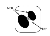
次に、CPU38は、メモリM2に格納されている画像信号の各画素の輝度値を所定の第1閾値(図6において破線で示される)と比較して、2値化する(S106)。即ち、CPU38は、第1閾値より輝度値が低い画素の、当該輝度値を表す8個のビットを全て“0”に書き換える。他方、第1閾値より輝度値が高い画素の、当該輝度値を表す8個のビットを全て“1”に書き換える。これによって、図7及び図8に示されるように、管空部Aと管壁部Bとが区分けされ、管壁部Bに対応する画素のみが輝度値“11111111”を有するようになる。
【0058】
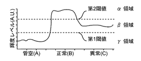
ところで、メモリMFには、図9に示すような輝度値(8ビットで表される二進値)の分布を有するF画像信号が、格納されている。そこで、CPU38は、メモリM2に格納された各画素の輝度値を構成する各ビットの値とメモリMFに格納された各画素の輝度値を構成する各ビットの値とについて論理積(AND)演算を行い、その演算結果をメモリMFに上書きする(S107)。これによって、図10及び図11に示すように、F画像信号のうち管空部Aに対応する部分がマスクされ、残りの管壁部B(腫瘍部位Cを含む)に対応する部分のみが元の状態のままとなっている画像信号が、メモリMFに保持されるようになる。なお、このメモリMFに格納された画像信号のうち管壁部Bを示す部分の輝度値は、図11に示すように、正常部位の方が腫瘍部位Cよりも高くなっている。
【0059】
次に、CPU38は、メモリMFに格納された画像信号の各画素の輝度値を所定の第2閾値(図11において破線で示されるように第1閾値よりも大きい値)と比較して、2値化する(S108)。即ち、CPU38は、第2閾値よりも低いβ領域及びγ領域に輝度値が存する画素の、当該輝度値を表す8個のビットを全て“0”に書き換える。他方、第2閾値より高いα領域に輝度値が存する画素の、当該輝度値を表す8個のビットを全て“1”に書き換える。これによって、管壁部Bから正常部位のみが抽出され、この正常部位のみが輝度値“11111111”を有するようになる。
【0060】
次に、CPU38は、メモリM2に格納された各画素の輝度値を構成する各ビットの値とメモリMFに格納された各画素の輝度値を構成する各ビットの値とについて排他OR演算を行い、その演算結果をメモリM2に上書きする(S109)。これによって、図12及び図13に示されるように、腫瘍部位Cの形状及び位置を示す画像信号が、メモリM2に保持されるようになる。
【0061】
続いて、CPU38は、メモリM1に格納されている画像信号(通常観察画像のデータ)をVRAM41の左側の領域に書き込む(S110)。次に、CPU38は、通常観察画像の静止画像と自家蛍光の強度に基づいて判定された腫瘍部位Cの画像(輝度値がβ領域に属する画素からなる特定領域を示す画像)とを合成した画像(通常観察画像中に特定領域を青色でスーパーインポーズした画像)を、生成する。即ち、CPU38は、メモリM2に格納されている画像信号中の輝度値が“11111111”である画素(腫瘍部位Cに属する画素)をメモリM1にマッピングし、メモリM1上において、マッピングされた画素のカラーを例えばB(青)に設定する(S111)。これにより、メモリM1上では、通常観察画像のうちの腫瘍部位C(異常部位)に対応する領域が青で示された蛍光診断用画像の静止画データが、生成される。そして、CPU38は、メモリM1に格納された蛍光診断用画像のデータをVRAM41の右側の領域に書き込む(S112)。 以上のようにしてVRAM41全体が画像データで満たされると、CPU38は、VRAM41の格納内容(モニタ15に表示すべき画像を示す画像データ)を、D/Aコンバータ37へ向けて出力する(S113)。
【0062】
VRAM41の格納内容は、D/Aコンバータ37を経てモニタ15に供給される。これによって、モニタ15の右側の表示領域に、腫瘍部位Cを青で示した蛍光診断用画像の静止画が表示される。
【0063】
その後、CPU38は、光源装置12及びビデオプロセッサ13を通常観察状態にて動作させる旨の制御命令を、光源制御部27及びMIC35に与え(S114)、このサブルーチンを終了させる。S114の制御命令を受けたMIC35は、スイッチSWのスイッチ片を出力端子T1と接触させる。また、光源制御部27は、第1ミラー25及び第2ミラー26を照明光及び励起光の光路から退避させる。これによって、電子内視鏡装置10が再び通常観察時の状態となり、図14に示すように、モニタ15の左側の表示領域に表示される通常観察画像が動画となる。
〔電子内視鏡装置の使用例〕
次に、上述した電子内視鏡装置10の使用例を説明する。最初に、電子内視鏡装置10の操作者は、光源装置12,ビデオプロセッサ13,PC14及びモニタ15の電源を投入する。これによって、PC14のCPU38が図3に示したメインルーチンを実行し、モニタ15の左側の表示領域には、被写体の通常観察画像が表示される。
【0064】
続いて、操作者は、電子内視鏡11の挿入部16を体腔内に挿入し、モニタ15に表示される通常観察画像を観察しながら腫瘍部位Cと予想される部位を探索する。
【0065】
その後、腫瘍部位Cと予想される部位がモニタ15に表示されると(図5参照)、操作者は、外部スイッチ36aを投入する。すると、PC14のCPU38は、図4に示した蛍光診断用画像生成処理を実行する。これによって、モニタ15の右側の表示領域に蛍光診断用画像が表示される。
【0066】
このとき、蛍光診断用画像に青で表示された領域がある場合には、腫瘍部位Cと予想される部位が実際に腫瘍部位である可能性が高く、青で表示された領域がない場合には、腫瘍部位Cと予想される部位が正常部位である可能性が高い。そして、操作者は、通常観察画像と蛍光診断用画像とに基づいて、腫瘍部位Cと予想される部位が実際に腫瘍部位か否かの診断を行う。
〔実施形態の効果〕
本実施形態の電子内視鏡装置10によると、操作者が腫瘍部位Cと予想される部位にて外部スイッチ36aを投入すれば、PC14のCPU38が、自家蛍光の強度の相違に基づいて、自家蛍光画像から腫瘍部位C(輝度値がβ領域に属する画素からなる部位)を抽出し、腫瘍部位Cが青で表示された蛍光診断用画像をモニタ15に表示させる。このため、操作者は、腫瘍部位Cと予想される部位が実際に主要部であるか否かを適正に診断することができる。
【0067】
また、本実施形態の電子内視鏡装置10によると、イメージインテンシファイアを有していなくても腫瘍部位Cを適正に示す蛍光診断画像をモニタ15に表示させることができる。このため、電子内視鏡装置10の構成を簡易にでき、コストの低減を図ることができる。特に、イメージインテンシファイアを電子内視鏡の先端部に配置する必要がないので、電子内視鏡の先端部が太くなってしまうのを防止することができ、患者の負担を軽減することができる。
【0068】
なお、本実施形態では、メモリM1に格納された通常観察画像のうち腫瘍部位(自家蛍光画像において輝度値がβ領域に属している部位)に対応する領域を青で示した蛍光診断用画像をモニタ15に表示させる構成としたが、メモリMFに格納された自家蛍光画像のうちの腫瘍部位(自家蛍光画像において輝度値がβ領域に属している部位)を青で示した蛍光診断画像をモニタ15に表示させるようにしても良い。
【0069】
また、本実施形態では、蛍光診断時におけるCCD17の出力信号をアンプ32で増幅する構成としたが、アンプ32の他にフレーム加算を用いてCCD17の出力信号を増幅しても良い。
【0070】
【発明の効果】
本発明による蛍光診断用電子内視鏡装置によれば、イメージインテンシファイアを有していなくても、適正な蛍光診断用の画像を得ることができ、蛍光診断用電子内視鏡装置の構成を簡易にすることができるとともに、コストの低減を図ることができる。
【0071】
【図面の簡単な説明】
【図1】本発明の実施の形態である蛍光診断用電子内視鏡装置の構成図
【図2】図1に示したPCの構成図
【図3】図2に示したCPUによる処理のメインルーチンを示すフローチャート
【図4】図3に示した蛍光診断用画像生成処理サブルーチンを示すフローチャート
【図5】通常観察画像の表示例を示す図
【図6】通常観察画像における輝度分布を示すグラフ
【図7】第1閾値に基づく二値化後の通常観察画像の表示例を示す図
【図8】第1閾値に基づく二値化後の通常観察画像における輝度分布を示すグラフ
【図9】自家蛍光画像における輝度分布を示すグラフ
【図10】論理積処理後の自家蛍光画像の表示例を示す図
【図11】論理積処理後の自家蛍光画像における輝度分布を示すグラフ
【図12】第2閾値に基づく二値化後の自家蛍光画像の表示例を示す図
【図13】第2閾値に基づく二値化後の自家蛍光画像における輝度分布を示すグラフ
【図14】モニタ上に表示される画面例を示す図
【符号の説明】
10 蛍光診断用電子内視鏡装置
11 電子内視鏡
12 光源装置
13 ビデオプロセッサ
14 パーソナルコンピュータ
17 CCD
36 外部スイッチ
38 CPU[0001]
TECHNICAL FIELD OF THE INVENTION
The present invention relates to an electronic endoscope apparatus for fluorescence diagnosis that images the inside of a body cavity based on autofluorescence emitted from a living body and outputs image data used for diagnosis of whether the living body is normal or abnormal. About.
[0002]
[Prior art]
It is known that when a living body is irradiated with excitation light of a specific wavelength, the living body emits fluorescence (this fluorescence is called “autofluorescence”). Furthermore, since the intensity of the autofluorescent green light region is lower at the abnormal part (tumor, cancer) of the living body than at the normal part, when represented as an image, the abnormal part may be displayed darker than the normal part. Are known.
[0003]
Based on this knowledge, the world's pioneering professor, Professor Haruhumi Kato of Tokyo Medical University, captured the autofluorescence of a living body and created an autofluorescence image that was used to diagnose whether the living body was normal or abnormal. An electronic endoscope apparatus for fluorescent diagnosis to be displayed was proposed, and based on this proposal, the applicant of the present invention has proceeded with the development, and as a result, an example has been disclosed in Japanese Patent Application Laid-Open No. 9-70384. is there.
[0004]
In the electronic endoscope apparatus for fluorescence diagnosis disclosed in this publication, it is considered that the auto-fluorescence is very weak light, and between the objective optical system and the imaging device at the tip of the electronic endoscope, An image intensifier that amplifies autofluorescence is provided. Therefore, according to the fluorescence diagnostic electronic endoscope, an image of the autofluorescence amplified by the image intensifier is picked up by the imaging device, so that a bright autofluorescence image can be obtained.
[0005]
[Problems to be solved by the invention]
However, when the image intensifier is incorporated in the distal end portion of the electronic endoscope, the outer diameter of the distal end portion becomes large. Since the distal end is a part to be inserted into the body cavity of the patient, there is a problem that if the distal end is too thick, a burden is imposed on the patient. Further, since the image intensifier is relatively expensive, there is also a problem that if the image intensifier is incorporated into the distal end portion of the electronic endoscope, the cost of the entire fluorescence diagnostic electronic endoscope apparatus increases.
[0006]
An object of the present invention is to provide an electronic endoscope apparatus for fluorescence diagnosis that can obtain an appropriate fluorescence diagnosis image without using an image intensifier.
[0007]
[Means for Solving the Problems]
The present invention has the following features to attain the object mentioned above.
[0008]
That is, the invention of
[0009]
With this configuration, the detection unit But special Since the constant region is extracted and the display control device outputs an image signal indicating the specific region, an image indicating the shape and position of the specific region can be displayed on a display device such as a CRT or a liquid crystal display. Therefore, if the luminance range of the specific region extracted by the detection unit is set to a range to which the luminance of the autofluorescence emitted from the abnormal part of the living body belongs, the abnormal part is displayed as the specific region. For this reason, even if it does not have an image intensifier, an appropriate image for fluorescence diagnosis can be provided to the user (doctor, etc.) of the electronic endoscope apparatus for fluorescence observation, and the user can appropriately generate the autofluorescence. Based diagnosis can be made.
[0010]
Here, the detection unit and the display control device can be configured as a function by executing a program of a CPU (central processing unit), for example, and can also be configured as an LSI, an ASIC, or the like.
[0013]
[0014]
[0015]
Claims 4 The invention described in the
[0016]
Claims 5 The invention described in the claims 4 Is output by outputting an image signal for simultaneously displaying the color image and the fluorescence observation image. With this configuration, the user can compare and observe the two images, so that normal / abnormal diagnosis of the living body can be easily performed.
[0017]
[0018]
[0019]
BEST MODE FOR CARRYING OUT THE INVENTION
Hereinafter, embodiments of the present invention will be described with reference to the drawings.
(Configuration of electronic endoscope device)
FIG. 1 is a schematic configuration diagram of an electronic endoscope apparatus for fluorescence observation (hereinafter, simply referred to as “electronic endoscope apparatus”) 10 according to the present embodiment. In FIG. 1, an
[0020]
Although only the
[0021]
An objective
[0022]
On the other hand, on the proximal end side of the light distribution lens 21, a light guide fiber bundle (hereinafter, “light”) passed through the
[0023]
The
[0024]
In the middle of the optical path of the illumination light between the
[0025]
Further, inside the
[0026]
Further, the
[0027]
The
[0028]
The A /
[0029]
The
[0030]
On the other hand, the output terminal T2 of the switch SW is connected to the input terminal of the
[0031]
Output terminals of the
[0032]
The
[0033]
Further, the
[0034]
The
[0035]
The
[0036]
The
[0037]
The
[0038]
The
[0039]
Hereinafter, an operation example of the electronic endoscope apparatus including the respective devices having the above-described configuration will be described along processing by the
[0040]
FIG. 3 is a flowchart showing a process (main routine) by the
[0041]
After the start, first, the
[0042]
By performing the above-described control from S1 to S3, white illumination light is emitted from the white light source 22. The white illumination light passes through the
[0043]
When the subject is sequentially illuminated with each illumination light, the reflected light from the subject forms an image of the subject on the imaging surface of the CCD 17 by the objective
[0044]
When this control signal is input, each of the
[0045]
Then, the
[0046]
Subsequently, the
[0047]
The above operation is an operation during normal observation. FIG. 5 shows a normal observation image including a tracheal tube cavity A and a tracheal tube wall B as a normal observation image of a subject. However, although the tumor region C is actually included in the tube wall portion B, the luminance distribution of the normal observation image is as shown in FIG. Almost indistinguishable.
[0048]
Next, the operation of the
[0049]
When the
[0050]
FIG. 4 is a flowchart showing a fluorescence diagnostic image creation processing subroutine executed in S8. When entering this subroutine, the
[0051]
Subsequently, the
[0052]
By executing the control in S102 and S103, the excitation light emitted from the UV
[0053]
The light from the subject including the reflected light of the autofluorescence and the excitation light enters the objective
[0054]
Thereafter, the F image signal is transmitted to the
[0055]
Then, the
[0056]
Subsequently, the
[0057]
Next, the
[0058]
By the way, an F image signal having a distribution of luminance values (binary values represented by 8 bits) as shown in FIG. 9 is stored in the memory MF. Therefore, the
[0059]
Next, the
[0060]
Next, the
[0061]
Subsequently, the
[0062]
The contents stored in the
[0063]
Thereafter, the
(Example of use of electronic endoscope device)
Next, a usage example of the above-described
[0064]
Subsequently, the operator inserts the
[0065]
Thereafter, when a site expected to be a tumor site C is displayed on the monitor 15 (see FIG. 5), the operator turns on the
[0066]
At this time, if there is a region displayed in blue in the fluorescence diagnostic image, it is highly likely that the site predicted to be the tumor site C is actually a tumor site, and if there is no region displayed in blue. Indicates that the site predicted as the tumor site C is likely to be a normal site. Then, based on the normal observation image and the image for fluorescence diagnosis, the operator makes a diagnosis as to whether or not the site expected to be the tumor site C is actually a tumor site.
[Effects of Embodiment]
According to the
[0067]
In addition, according to the
[0068]
In the present embodiment, a fluorescence diagnosis image in which a region corresponding to a tumor site (a site whose luminance value belongs to the β region in the autofluorescence image) in the normal observation image stored in the memory M1 is shown in blue. Although the
[0069]
In this embodiment, the output signal of the CCD 17 at the time of the fluorescence diagnosis is configured to be amplified by the
[0070]
【The invention's effect】
ADVANTAGE OF THE INVENTION According to the electronic endoscope apparatus for a fluorescence diagnosis by this invention, even if it does not have an image intensifier, the image for an appropriate fluorescence diagnosis can be obtained and the structure of the electronic endoscope apparatus for a fluorescence diagnosis Can be simplified, and the cost can be reduced.
[0071]
[Brief description of the drawings]
FIG. 1 is a configuration diagram of an electronic endoscope apparatus for fluorescence diagnosis according to an embodiment of the present invention.
FIG. 2 is a configuration diagram of a PC shown in FIG. 1;
FIG. 3 is a flowchart showing a main routine of processing by a CPU shown in FIG. 2;
FIG. 4 is a flowchart showing a fluorescence diagnostic image generation processing subroutine shown in FIG. 3;
FIG. 5 is a diagram showing a display example of a normal observation image.
FIG. 6 is a graph showing a luminance distribution in a normal observation image.
FIG. 7 is a diagram showing a display example of a normal observation image after binarization based on a first threshold value;
FIG. 8 is a graph showing a luminance distribution in a normal observation image after binarization based on a first threshold.
FIG. 9 is a graph showing a luminance distribution in an autofluorescence image.
FIG. 10 is a diagram showing a display example of an autofluorescence image after a logical product process;
FIG. 11 is a graph showing a luminance distribution in an autofluorescence image after the logical product processing;
FIG. 12 is a diagram illustrating a display example of an autofluorescence image after binarization based on a second threshold value;
FIG. 13 is a graph showing a luminance distribution in an autofluorescence image after binarization based on a second threshold.
FIG. 14 is a diagram showing an example of a screen displayed on a monitor.
[Explanation of symbols]
10. Electronic endoscope device for fluorescence diagnosis
11 Electronic endoscope
12 Light source device
13 Video Processor
14 Personal computer
17 CCD
36 External switch
38 CPU
Claims (7)
前記通常観察画像から第1の閾値より高い輝度領域を抽出し、前記自家蛍光画像から第2の閾値より低い輝度領域を抽出し、前記通常観察画像から抽出された領域のうち、自家蛍光画像から抽出された領域にも含まれる領域を特定領域として検出する検出部と、
前記特定領域を示す画像信号を出力する表示制御装置
とを備えたことを特徴とする蛍光診断用電子内視鏡装置。 And has a lighting device for illuminating the living body by switching between the excitation light of the illumination light and ultraviolet bands of the visible spectrum, illuminating the normal observation image and the excitation light of the living body irradiated with illumination light of the visible band to the living body an imaging device for each of an image of the autofluorescence of the living body caused by,
A luminance region higher than a first threshold value is extracted from the normal observation image, a luminance region lower than a second threshold value is extracted from the autofluorescence image, and a region extracted from the normal observation image is extracted from the autofluorescence image. A detection unit that detects a region included in the extracted region as a specific region ,
Display control equipment that outputs an image signal indicative of the specific area
Preparative fluorescence diagnostic electronic endoscope apparatus comprising the.
ことを特徴とする請求項1記載の蛍光診断用電子内視鏡装置。The electronic endoscope apparatus for fluorescence diagnosis according to claim 1, wherein the display control device outputs an image signal for displaying a fluorescence observation image in which only the specific region is displayed in a predetermined color.
ことを特徴とする請求項1記載の蛍光診断用電子内視鏡装置。The display control device according to claim 1, characterized in that outputs an image signal for displaying the fluorescence observation image showing other than the specific region in color with showing only the specific area of the normal observation image in a single color An electronic endoscope apparatus for fluorescence diagnosis according to the above.
前記表示制御装置は、前記各照明光が照射された時の前記生体の通常観察画像に基づいてカラー画像を合成するとともに、前記自家蛍光画像から前記特定領域のみを抽出した特定領域画像を生成し、前記カラー画像上に前記特定領域画像をスーパーインポーズしてなる蛍光観察画像を表示するための画像信号を出力する
ことを特徴とする請求項3記載の蛍光診断用電子内視鏡装置。The imaging device, by illuminating the living body in sequence with red, green, and blue illumination light by the illumination device, respectively captures a normal observation image of the living body when each illumination light is irradiated,
The display control device synthesizes a color image based on the normal observation image of the living body when each of the illumination lights is irradiated, and generates a specific region image in which only the specific region is extracted from the autofluorescence image. 4. An electronic endoscope apparatus for fluorescence diagnosis according to claim 3 , wherein an image signal for displaying a fluorescence observation image obtained by superimposing the specific area image on the color image is output.
ことを特徴とする請求項4記載の蛍光診断用電子内視鏡装置。The electronic endoscope apparatus for fluorescence diagnosis according to claim 4 , wherein the display control device outputs an image signal for simultaneously displaying the color image and the fluorescence observation image.
ことを特徴とする請求項1記載の蛍光診断用電子内視鏡装置。The display control device, the normal observation image fluorescence diagnostic electronic endoscope apparatus according to claim 1, wherein the outputting the image signal for displaying the videos.
ことを特徴とする請求項5記載の蛍光診断用電子内視鏡装置。An image signal for displaying only the normal observation image and an image signal for simultaneously displaying the normal observation image and the fluorescence diagnostic image, which are operated by an operator, for switching the display control device. The electronic endoscope apparatus for fluorescence diagnosis according to claim 5 , further comprising a switch for generating a switching signal.
Priority Applications (1)
| Application Number | Priority Date | Filing Date | Title |
|---|---|---|---|
| JP11339699A JP3574591B2 (en) | 1998-05-01 | 1999-04-21 | Electronic endoscope device for fluorescence diagnosis |
Applications Claiming Priority (3)
| Application Number | Priority Date | Filing Date | Title |
|---|---|---|---|
| JP12256198 | 1998-05-01 | ||
| JP10-122561 | 1998-05-01 | ||
| JP11339699A JP3574591B2 (en) | 1998-05-01 | 1999-04-21 | Electronic endoscope device for fluorescence diagnosis |
Publications (2)
| Publication Number | Publication Date |
|---|---|
| JP2000023903A JP2000023903A (en) | 2000-01-25 |
| JP3574591B2 true JP3574591B2 (en) | 2004-10-06 |
Family
ID=26452385
Family Applications (1)
| Application Number | Title | Priority Date | Filing Date |
|---|---|---|---|
| JP11339699A Expired - Fee Related JP3574591B2 (en) | 1998-05-01 | 1999-04-21 | Electronic endoscope device for fluorescence diagnosis |
Country Status (1)
| Country | Link |
|---|---|
| JP (1) | JP3574591B2 (en) |
Families Citing this family (19)
| Publication number | Priority date | Publication date | Assignee | Title |
|---|---|---|---|---|
| JP3762623B2 (en) * | 2000-08-10 | 2006-04-05 | ペンタックス株式会社 | Electronic endoscope switchable between normal light illumination and special wavelength light illumination |
| JP2002034913A (en) * | 2000-07-27 | 2002-02-05 | Asahi Optical Co Ltd | Optical system of light source device of electronic endoscope system |
| JP4520016B2 (en) * | 2000-11-16 | 2010-08-04 | Hoya株式会社 | Electronic endoscope device |
| JP2002153414A (en) * | 2000-11-17 | 2002-05-28 | Asahi Optical Co Ltd | Electronic endoscope and electronic endoscope system |
| JP4681740B2 (en) * | 2001-01-29 | 2011-05-11 | Hoya株式会社 | Electronic endoscope device for simultaneous capture of strobe images |
| JP2003061909A (en) * | 2001-08-22 | 2003-03-04 | Pentax Corp | Light source device and electronic endoscope device |
| JP4199510B2 (en) | 2002-09-30 | 2008-12-17 | Hoya株式会社 | Diagnostic aid device |
| EP1614378A4 (en) | 2003-04-03 | 2009-07-29 | Kao Corp | Carious tooth detection device |
| US20080017787A1 (en) * | 2004-04-30 | 2008-01-24 | J. Morita Manufacturing Corporation | Living Body Observing Apparatus, Intraoral Imaging Apparatus and Medical Treatment Appliance |
| JP2006020788A (en) * | 2004-07-07 | 2006-01-26 | Pentax Corp | Electronic endoscope apparatus and system capable of autofluorescence observation |
| JP2006043196A (en) * | 2004-08-05 | 2006-02-16 | Pentax Corp | Electronic endoscope system and processor for electronic endoscope |
| JP2006116153A (en) * | 2004-10-22 | 2006-05-11 | Olympus Corp | Image processing apparatus for endoscope and endoscope apparatus |
| JP4587811B2 (en) * | 2005-01-11 | 2010-11-24 | オリンパス株式会社 | Fluorescence observation endoscope device |
| JP2006198106A (en) | 2005-01-19 | 2006-08-03 | Olympus Corp | Electronic endoscope system |
| EP2679137B1 (en) * | 2011-06-07 | 2016-03-23 | Olympus Corporation | Endoscope apparatus for controlling light quantity of fluorescence imaging |
| JP6442141B2 (en) * | 2014-01-23 | 2018-12-19 | オリンパス株式会社 | Light source system for endoscope having light source module and light source module |
| JP6389652B2 (en) * | 2014-06-13 | 2018-09-12 | オリンパス株式会社 | Endoscope |
| JP7306461B2 (en) * | 2019-08-02 | 2023-07-11 | 株式会社島津製作所 | Treatment support device and treatment support method |
| JP7411515B2 (en) * | 2020-07-16 | 2024-01-11 | 富士フイルム株式会社 | Endoscope system and its operating method |
Family Cites Families (5)
| Publication number | Priority date | Publication date | Assignee | Title |
|---|---|---|---|---|
| JP2836863B2 (en) * | 1989-02-21 | 1998-12-14 | オリンパス光学工業株式会社 | Endoscope insertion control device |
| DE4026821A1 (en) * | 1990-08-24 | 1992-03-05 | Philips Patentverwaltung | METHOD FOR DETECTING ANOMALIES OF THE SKIN, ESPECIALLY MELANOMAS, AND DEVICE FOR IMPLEMENTING THE METHOD |
| JP3285265B2 (en) * | 1993-12-03 | 2002-05-27 | オリンパス光学工業株式会社 | Fluorescence observation device |
| JPH07250804A (en) * | 1994-03-15 | 1995-10-03 | Olympus Optical Co Ltd | Fluorescence observer |
| JP3467131B2 (en) * | 1994-09-21 | 2003-11-17 | ペンタックス株式会社 | Electronic endoscope device for fluorescence diagnosis |
-
1999
- 1999-04-21 JP JP11339699A patent/JP3574591B2/en not_active Expired - Fee Related
Also Published As
| Publication number | Publication date |
|---|---|
| JP2000023903A (en) | 2000-01-25 |
Similar Documents
| Publication | Publication Date | Title |
|---|---|---|
| JP3574591B2 (en) | Electronic endoscope device for fluorescence diagnosis | |
| US6371908B1 (en) | Video endoscopic apparatus for fluorescent diagnosis | |
| JP7135082B2 (en) | Endoscope device, method of operating endoscope device, and program | |
| US20020021355A1 (en) | Video endoscope system | |
| JP2004024611A (en) | Image processor for fluorescent observation | |
| JPWO2015156153A1 (en) | Fluorescence observation endoscope system | |
| JP4190917B2 (en) | Endoscope device | |
| WO2003075752A1 (en) | Endoscope image processing apparatus | |
| JP2004024656A (en) | Fluorescent endoscope equipment | |
| JP2001137174A (en) | Method for displaying fluorescence image and equipment | |
| JP2006166940A (en) | Lighting device for endoscope | |
| WO2020178962A1 (en) | Endoscope system and image processing device | |
| JP3884265B2 (en) | Endoscope device | |
| JP2003061909A (en) | Light source device and electronic endoscope device | |
| JP2003164414A (en) | Method and device for displaying fluoroscopic image | |
| JP4495513B2 (en) | Fluorescence endoscope device | |
| JP2010094153A (en) | Electron endoscopic system and observation image forming method | |
| JP2002345739A (en) | Image display device | |
| JP4459709B2 (en) | Fluorescence observation endoscope device | |
| JP5331394B2 (en) | Endoscope device | |
| JP2010094152A (en) | Electron endoscopic system | |
| JP4242578B2 (en) | Endoscope device | |
| JP4575208B2 (en) | Electronic endoscope device | |
| JP4426225B2 (en) | Fluorescence observation endoscope system and light source device for fluorescence observation endoscope | |
| JP2008043383A (en) | Fluorescence observation endoscope device |
Legal Events
| Date | Code | Title | Description |
|---|---|---|---|
| A977 | Report on retrieval |
Free format text: JAPANESE INTERMEDIATE CODE: A971007 Effective date: 20040319 |
|
| A131 | Notification of reasons for refusal |
Free format text: JAPANESE INTERMEDIATE CODE: A131 Effective date: 20040330 |
|
| A521 | Written amendment |
Free format text: JAPANESE INTERMEDIATE CODE: A523 Effective date: 20040527 |
|
| TRDD | Decision of grant or rejection written | ||
| A01 | Written decision to grant a patent or to grant a registration (utility model) |
Free format text: JAPANESE INTERMEDIATE CODE: A01 Effective date: 20040622 |
|
| A61 | First payment of annual fees (during grant procedure) |
Free format text: JAPANESE INTERMEDIATE CODE: A61 Effective date: 20040702 |
|
| R150 | Certificate of patent or registration of utility model |
Free format text: JAPANESE INTERMEDIATE CODE: R150 |
|
| FPAY | Renewal fee payment (event date is renewal date of database) |
Free format text: PAYMENT UNTIL: 20090709 Year of fee payment: 5 |
|
| FPAY | Renewal fee payment (event date is renewal date of database) |
Free format text: PAYMENT UNTIL: 20100709 Year of fee payment: 6 |
|
| FPAY | Renewal fee payment (event date is renewal date of database) |
Free format text: PAYMENT UNTIL: 20110709 Year of fee payment: 7 |
|
| FPAY | Renewal fee payment (event date is renewal date of database) |
Free format text: PAYMENT UNTIL: 20120709 Year of fee payment: 8 |
|
| FPAY | Renewal fee payment (event date is renewal date of database) |
Free format text: PAYMENT UNTIL: 20120709 Year of fee payment: 8 |
|
| FPAY | Renewal fee payment (event date is renewal date of database) |
Free format text: PAYMENT UNTIL: 20130709 Year of fee payment: 9 |
|
| LAPS | Cancellation because of no payment of annual fees |