EP3097397B1 - Système de mesure de rail - Google Patents
Système de mesure de rail Download PDFInfo
- Publication number
- EP3097397B1 EP3097397B1 EP15702154.4A EP15702154A EP3097397B1 EP 3097397 B1 EP3097397 B1 EP 3097397B1 EP 15702154 A EP15702154 A EP 15702154A EP 3097397 B1 EP3097397 B1 EP 3097397B1
- Authority
- EP
- European Patent Office
- Prior art keywords
- fiber
- rail
- sensor unit
- optic sensor
- neutral axis
- Prior art date
- Legal status (The legal status is an assumption and is not a legal conclusion. Google has not performed a legal analysis and makes no representation as to the accuracy of the status listed.)
- Active
Links
Images


Classifications
-
- G—PHYSICS
- G01—MEASURING; TESTING
- G01M—TESTING STATIC OR DYNAMIC BALANCE OF MACHINES OR STRUCTURES; TESTING OF STRUCTURES OR APPARATUS, NOT OTHERWISE PROVIDED FOR
- G01M11/00—Testing of optical apparatus; Testing structures by optical methods not otherwise provided for
- G01M11/08—Testing mechanical properties
-
- G—PHYSICS
- G01—MEASURING; TESTING
- G01L—MEASURING FORCE, STRESS, TORQUE, WORK, MECHANICAL POWER, MECHANICAL EFFICIENCY, OR FLUID PRESSURE
- G01L1/00—Measuring force or stress, in general
- G01L1/24—Measuring force or stress, in general by measuring variations of optical properties of material when it is stressed, e.g. by photoelastic stress analysis using infrared, visible light, ultraviolet
- G01L1/242—Measuring force or stress, in general by measuring variations of optical properties of material when it is stressed, e.g. by photoelastic stress analysis using infrared, visible light, ultraviolet the material being an optical fibre
- G01L1/246—Measuring force or stress, in general by measuring variations of optical properties of material when it is stressed, e.g. by photoelastic stress analysis using infrared, visible light, ultraviolet the material being an optical fibre using integrated gratings, e.g. Bragg gratings
-
- B—PERFORMING OPERATIONS; TRANSPORTING
- B61—RAILWAYS
- B61K—AUXILIARY EQUIPMENT SPECIALLY ADAPTED FOR RAILWAYS, NOT OTHERWISE PROVIDED FOR
- B61K9/00—Railway vehicle profile gauges; Detecting or indicating overheating of components; Apparatus on locomotives or cars to indicate bad track sections; General design of track recording vehicles
- B61K9/08—Measuring installations for surveying permanent way
-
- B—PERFORMING OPERATIONS; TRANSPORTING
- B61—RAILWAYS
- B61L—GUIDING RAILWAY TRAFFIC; ENSURING THE SAFETY OF RAILWAY TRAFFIC
- B61L23/00—Control, warning or like safety means along the route or between vehicles or trains
- B61L23/04—Control, warning or like safety means along the route or between vehicles or trains for monitoring the mechanical state of the route
- B61L23/042—Track changes detection
- B61L23/047—Track or rail movements
-
- B—PERFORMING OPERATIONS; TRANSPORTING
- B61—RAILWAYS
- B61L—GUIDING RAILWAY TRAFFIC; ENSURING THE SAFETY OF RAILWAY TRAFFIC
- B61L25/00—Recording or indicating positions or identities of vehicles or trains or setting of track apparatus
- B61L25/02—Indicating or recording positions or identities of vehicles or trains
- B61L25/021—Measuring and recording of train speed
-
- G—PHYSICS
- G01—MEASURING; TESTING
- G01L—MEASURING FORCE, STRESS, TORQUE, WORK, MECHANICAL POWER, MECHANICAL EFFICIENCY, OR FLUID PRESSURE
- G01L1/00—Measuring force or stress, in general
- G01L1/24—Measuring force or stress, in general by measuring variations of optical properties of material when it is stressed, e.g. by photoelastic stress analysis using infrared, visible light, ultraviolet
- G01L1/247—Measuring force or stress, in general by measuring variations of optical properties of material when it is stressed, e.g. by photoelastic stress analysis using infrared, visible light, ultraviolet using distributed sensing elements, e.g. microcapsules
-
- G—PHYSICS
- G01—MEASURING; TESTING
- G01M—TESTING STATIC OR DYNAMIC BALANCE OF MACHINES OR STRUCTURES; TESTING OF STRUCTURES OR APPARATUS, NOT OTHERWISE PROVIDED FOR
- G01M11/00—Testing of optical apparatus; Testing structures by optical methods not otherwise provided for
- G01M11/08—Testing mechanical properties
- G01M11/083—Testing mechanical properties by using an optical fiber in contact with the device under test [DUT]
- G01M11/085—Testing mechanical properties by using an optical fiber in contact with the device under test [DUT] the optical fiber being on or near the surface of the DUT
Definitions
- the present application relates in general to an optical measuring device for detecting measured variables by means of sensors embedded in optical fibers, and in particular to a use of at least one fiber-optic sensor element for measuring a mechanical variable which acts on a rail, and a rail measuring system. Furthermore, the present application relates to a method for attaching a fiber optic sensor element to a rail.
- one or more embedded in optical waveguide sensors such as fiber Bragg gratings, are used to detect an induced by a mechanical size expansion of the optical fiber, and thus to detect the forces, torques, accelerations, loads, pressure conditions, etc. to be able to.
- the sensor elements integrated in fiber sensors are irradiated with optical radiation in a suitable wavelength range.
- the optical fiber is stretched, and a reflection wavelength of the fiber Bragg grating changes.
- a portion of the incident light is reflected by the sensor and fed to an evaluation and analysis unit.
- the wavelength change which is based on the applied force, can be investigated in the analysis unit and used to detect mechanical influences on the sensor element.
- the intensity and / or the wavelength range of the optical radiation reflected at the sensor element or the optical radiation transmitted through the sensor element have features that are influenced by the applied mechanical variable.
- the fiber-optic sensor elements integrated in the optical sensor fiber are sensitive to strains of the sensor fiber, among other things, as a result of the sensor element reflected or the transmitted through the sensor element wavelength spectrum is affected.
- strains of the optical fiber and thus of the optical sensor element in the fiber and / or changes in the fiber Bragg grating structure depend not only on the mechanical variable to be measured, such as the force, but can also by unwanted disturbances, such as For example, temperature fluctuations are influenced. It is thus desirable to eliminate or at least suppress disturbances which have an effect on the measurement accuracy in the detection of the desired values.
- CN 101 797 928 A discloses an axle counting system on a rail comprising a broadband light source, an optical circulator, an extensible fiber Bragg grating disposed on the rail, and a photodetector and a detector for evaluating the light signal / counting the axes.
- DE 695 21 971 T1 discloses an optical microsystem with dielectric conductors for measuring longitudinal stresses in the form of a rosette.
- a rosette a plurality of optical fibers are arranged at different angles to each other, which makes it possible to measure a longitudinal stress independent of the temperature.
- the present application provides a use of at least one fiber optic sensor element for measuring a mechanical quantity which is on a rail
- a use of at least one fiber optic sensor unit for measuring a mechanical quantity acting on a rail having a longitudinal extent and a neutral fiber extending along the length thereof wherein the use comprises attaching the at least one fiber optic sensor unit below one Angle of 30 ° to 60 °, in particular 45 °, relative to the neutral fiber or at an angle of -30 ° to -60 °, in particular -45 °, relative to the neutral fiber on the rail, irradiating the at least one fiber optic sensor unit with Primary light for generating a signal light in reflection or transmission, detecting the intensity of the signal light, and an evaluation of the signal light comprises.
- an attachment point of the fiber optic sensor unit is disposed on one side of the neutral fiber and another attachment point on the opposite side of the neutral fiber.
- the fiber optic sensor unit for detecting a mechanical force applied to a rail preferably comprises an optical fiber, a fiber Bragg grating provided in the optical fiber, having a mechanical force dependent Bragg wavelength, a transducer structure, the transducer structure a signal amplification lever, and an edge filter for filtering the first part of the signal light comprises, in particular wherein the edge filter has a filter characteristic with a nominal slope of 8% per nm based on the transmitted intensity or less, in particular between 2% - 7% per nm, In particular, wherein a range of axle loads acting on the rail of 200 kg to 50,000 kg is provided.
- an attachment point of the fiber optic sensor unit is disposed on one side of the neutral fiber and another attachment point on the opposite side of the neutral fiber.
- a method for attaching a fiber optic sensor unit to a rail in particular a fiber optic sensor unit with a fiber Bragg grating, is provided on a rail, the method comprising attaching the fiber optic sensor unit at a further angle of 30 ° up to 60 °, in particular 45 °, relative to the neutral fiber or at a further angle of -30 ° to -60 °, in particular -45 °, relative to the neutral fiber of the rail, in particular wherein the fiber optic sensor unit is attached approximately to the neutral fiber is.
- an attachment point of the fiber optic sensor unit is disposed on one side of the neutral fiber and another attachment point on the opposite side of the neutral fiber.
- a use of at least one fiber optic sensor unit for measuring a mechanical quantity acting on a rail with a longitudinal extent and a neutral fiber extending along the longitudinal extent preferably comprises providing the at least one fiber optic sensor unit to the neutral fiber, in particular so that the fiber optic sensor unit crossing the neutral fiber, irradiating the at least one fiber optic sensor unit with primary light to generate a signal light in reflection or transmission, detecting the intensity of the signal light, and evaluating the signal light.
- a rail measuring system comprising a rail having a longitudinal extent and a neutral fiber extending along the longitudinal extent, which is acted upon by a mechanical force generated by a train passing over it, and at least one fiber optic sensor unit, typically two fiber optic ones Sensor units, for Detecting the mechanical force acting on the rail, wherein a fiber optic sensor unit comprises a fiber Bragg grating having a mechanical size dependent Bragg wavelength, and wherein the at least one fiber optic sensor unit is attached to the neutral fiber, in particular the fitted with neutral fiber crossing.
- a method for attaching a fiber optic sensor unit, in particular a fiber optic sensor unit with a fiber Bragg grating, to a rail comprising attaching the fiber optic sensor unit to the neutral fiber of the rail in particular the fiber optic sensor unit crosses the neutral fiber.
- a measuring method for measuring a mechanical quantity acting on a rail having a longitudinal extent and a neutral fiber extending along the longitudinal extent comprising irradiating at least one primary-optical fiber-optic sensor unit to produce a Signal light in reflection or transmission, detecting the intensity of the signal light, and an evaluation of the signal light comprises, in particular with the signal light clipping occurs that is used to evaluate the signal light.
- Embodiments of the present invention described herein relate to, among others: a use of at least one fiber optic sensor unit for measuring a mechanical variable, a fiber optic sensor unit for detecting a mechanical force acting on a rail, a rail measuring system and a method for attaching a fiber optic sensor unit, in particular a fiber optic sensor unit with a fiber Bragg grating to a rail ,
- Fig. 1 illustrates a sensor integrated into an optical waveguide or a sensor element 303, which has a fiber Bragg grating 306.
- a fiber Bragg grating 306 is shown, it is to be understood that the present invention is not limited to data acquisition from a single fiber Bragg grating 306, but that along a transmission fiber and sensor fiber 304, respectively, is a plurality of fibers -Bragg gratings 306 may be arranged.
- Fig. 1 thus shows only a portion of an optical waveguide which is formed as a sensor fiber 304, wherein this sensor fiber 304 is sensitive to a fiber elongation 308.
- optical or "light” is intended to indicate a wavelength range in the electromagnetic spectrum, which may extend from the ultraviolet spectral range over the visible spectral range to the infrared spectral range.
- n k is the effective refractive index of the fundamental mode of the core of the sensor fiber 304 and ⁇ the spatial grating period (modulation period) of the fiber Bragg grating 306.
- a spectral width which is given by a half width of the reflection response, depends on the extent of the fiber Bragg grating 306 along the sensor fiber 304.
- the light propagation within the sensor fiber 304 is thus, for example, dependent on forces, moments and mechanical stresses as well as temperatures at which the sensor fiber 304 and in particular the fiber Bragg grating 306 within the sensor fiber 304 are acted upon by the effect of the fiber Bragg grating 306 ,
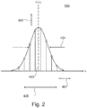
- measuring light 204 enters the sensor fiber 304 from the left, wherein a portion of the measuring light 204 emerges as a transmitted light 206 with a wavelength variation as compared to the measuring light 204. Further, it is possible to receive reflected light 205 at the input end of the fiber (ie, at the end where the measuring light 204 is also irradiated), the reflected light 204 also having a modified wavelength distribution, such as that shown in FIG Fig. 2 is shown (sensor reflection response).
- a transmission minimum results in the transmitted light 206 at the location of the Bragg wavelength Fig. 2 Inverse curve shown, ie maximum absorption at the Bragg wavelength). In the reflected light results at this point a reflection maximum, which below with reference to Fig. 2 is explained.
- Fig. 2 schematically illustrates a sensor reflection response 400 received when broadband measurement light 204 is irradiated and when the center wavelength of the fiber Bragg grating 306 (FIG. Fig. 1 ), ie the Bragg wavelength ⁇ B corresponding to the dashed line 403.
- the sensor reflection response 400 may have a symmetrical profile with respect to the center wavelength 403, the profile having a half-width 404 (FWHM, full width at half maximum), ie a spectral width at half the maximum intensity.
- Fig. 2 Schematically are in Fig. 2 here spatial sampling points (circles) marked.
- I intensity distribution
- ⁇ intensity distribution to be detected by the measuring device results from a wavelength response range 405 indicated by the double arrow in FIG Fig. 2
- Modified secondary light 203 has wavelength components in this region as the fiber Bragg grating 306 is measured.
- the modified secondary light 203 then corresponds to the in Fig. 2 Sensor reflection response 400, that is, a reflection intensity 402 is recorded as a function of the wavelength 401.
- FIG. 3 shows a schematic block diagram of a fiber optic measuring device with light source, fiber coupler and detection device or a fiber optic sensor unit, or a rail measuring system according to embodiments of the present invention.
- a rail 320 a fiber optic sensor unit 330 mounted on the rail, and an optical measuring device 340 are shown.
- the fiber optic sensor unit 330 can in the FIG. 2 be shown sensor unit 303, or be similar.
- the rail 320 may be considered approximately as a bar.
- a beam is generally a rod-shaped support member that can be loaded by loads transverse to its axis.
- the reaction of the beam to the loads are bending and shear deformations. For example, if a force acts on an attack surface of the beam, it deforms in the course of bending deformation in such a way that a first region facing the attack surface undergoes a contraction (negative expansion) and a second region facing away from the attack surface undergoes stretching (positive expansion) , Between these areas, an area is arranged which does not undergo stretching by the bend. This is called neutral fiber. In addition to the bend, the above shear deformation exists.
- Rail 320 has a foot 322 in a lower portion and a head 324 in an upper portion. Between these, an approximately rectangular region 326 is formed. When a mechanical amount acts on the rail 320, the rail 320 deforms to form a neutral fiber 328 as described above.
- the rail 320 is preferably formed so that the neutral fiber 328 is formed in the rectangular region 326.
- the fiber optic sensor unit makes an angle greater than or less than 0 ° with the neutral fiber.
- the fiber optic sensor unit is at an angle of 30 ° to 60 °, especially 45 °, relative to the neutral fiber or at an angle of -30 ° to -60 ° °, in particular -45 °, arranged relative to the neutral fiber.
- Attaching the fiber optic sensor unit 330 at an angle of ⁇ 30 ° to ⁇ 60 °, in particular ⁇ 45 °, relative to the neutral fiber offers the advantage that shear deformations are detected by the fiber optic sensor unit, which leads to a positive or negative strain not parallel to the neutral fiber.
- the fiber optic sensor unit is attached to the neutral fiber and straddling it so that the optical sensor unit is attached to the rail at two positions such that the sensor unit intersects with the neutral fiber, i. an attachment point is disposed on one side of the neutral fiber and the other attachment point is disposed on the opposite side of the neutral fiber.
- the attachment points of the neutral fiber can be queried gleichweit, ie symmetrically relative to the neutral fiber, in particular point symmetry, are arranged.
- the fiber optic sensor unit 330 is attached to the rail 320 via two attachment points 332, 334 that are, for example, equidistant from the neutral fiber.
- the bending deformations caused at the fastening points 332, 334 by a mechanical variable acting on the rail cancel each other out, as a result of which the shear deformation is measured substantially directly or substantially undisturbed.
- the fiber optic sensor unit may be substantially over or over the neutral fiber, i. cross. According to some embodiments which may be combined with other embodiments, the fiber optic sensor unit may be at an angle of 30 ° to 60 °, in particular 45 °, relative to the neutral fiber or at an angle of -30 ° to -60 °, in particular -45 ° °, are arranged relative to the neutral fiber. In particular, the fiber optic sensor unit may be substantially disposed on or over the neutral fiber, i.e., straddling it. cross over and at an angle of 30 ° to 60 °, in particular 45 °, relative to the neutral fiber or at an angle of -30 ° to -60 °. By such attachment types only shear deformations are introduced into the sensor. These are independent of the bending of the rail and thus independent of the exact bearing of the rail on the track bed and the sleepers.
- the optical measuring device shown comprises a primary light source 341, a fiber coupler 343 and a photodetector 345.
- An optical transmission fiber 342 is provided between the primary light source 341 and the fiber coupler 343.
- the fiber coupler 343 aligns the primary light 201 of the primary source 341 with the fiber optic sensor unit 330.
- the sensor reflection response 400, ie the signal light, returned by the fiber optic sensor unit 330 in response to the mechanical quantity acting on the rail 150 is in turn forwarded to the fiber coupler 343.
- the recirculated light or a part of the recirculated light is supplied as a secondary light 347 or signal light 347 to the photodetector 345.
- a detector detects the intensity distribution, preferably the intensity of the signal light. For example, the detector triggers a change in the center wavelength 403 of the secondary light 347 reflected back from the fiber optic sensor unit.
- a beam splitter 344 may be provided between the fiber coupler 343 and the photodetector 345 which splits the incident light and directs a first portion 347a to a photodetector 345 and directs a second portion 347b to a second photodetector 348 via a filter 346.
- the filter 346 is preferably designed as an edge filter.
- the evaluation of the signals at the first photodetector 345 and / or at the second photodetector 348 takes place in an evaluation unit, not shown, in which in particular the signal light can be evaluated.
- the signals can be processed together or billed together.
- the first and / or the second photodetector are designed as a photodiode, photomultiplier, avalanche photodiode or the like.
- Such photodetectors convert the incoming signal light into a photocurrent, which allows a quick and easy evaluation.
- a difference of the signals generated at the photodetectors 345, 348 formed as photodiodes can be formed.
- a detector can spectrally integrate the signal light, ie detect the intensity, for example after the edge filter, without a spectral resolution.
- the optical signals of the photodiodes can be read out after the edge filter at high frequency, in particular greater than 5 kHz, advantageously greater than 8 kHz, typically greater than 10 kHz, since a simple scanning of the photocurrents takes place.
- detection may also be performed by means of a spectrometer or the like to resolve the wavelength distribution reflected back from the fiber optic sensor unit 330 according to its spectrum.
- the use of photodetectors, in particular photodiodes offers the advantage of high-frequency scanning with a simple measurement setup.
- the nominal slope of the filter characteristic is preferably less than 8% nm, in particular in a range of 2% - 7%, based on the transmitted intensity.
- the nominal slope refers to the average slope of the edge filter, the slope in a significant / predominant area of the edge filter, or a slope characteristic of the edge filter, for example, as a representative value, to different edge filters with respect to their pitch to compare.
- a typical center wavelength 403 of the light reflected back from the fiber Bragg grating 306 is about 1550 nm. Other aspects of the dynamic range change will be discussed with reference to FIGS FIGS. 5A and 5B explained.
- the readout of the fiber Bragg grating signal ie the signal change of the fiber optic sensor unit caused by the mechanical variable acting on the rail, can be done by the just-shown edge filter structure, whereby a high-frequency measurement can be performed.
- a second or further fiber optic sensor unit is at a further angle of 30 ° to 60 °, in particular 45 °, relative to the neutral fiber or at a further angle of -30 ° to -60 °, in particular -45 °, relative to neutral fiber provided to increase the scope.
- the sign of the further angle of the further fiber-optic sensor unit differs from the sign of the angle of the fiber-optic sensor unit. In this case, by adding these two signals, a signal can be made available that is proportional to the load on the rail.
- a third or fourth sensor unit may also be arranged at the angles described herein. But they can also be arranged at other angles, such as 0 ° or 90 ° relative to the neutral fiber.
- the primary light can be intensity-modulated by the primary light source 341 prior to irradiation of the fiber-optic sensor units in order to eliminate or at least reduce unwanted interference, for example by means of a lock-in technique.
- the modulation frequency can be made available to the photodetectors in order to enable synchronized detection in the photodetectors.
- the fiber optic sensor units formed as fiber Bragg gratings can also be operated in transmission such that transmitted primary light 201 is supplied as a secondary light (transmitted secondary light) 202 to the optical measuring device.
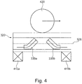
- the FIG. 4 shows a schematic of a rail measuring system according to another embodiment. It should be noted here that components already with reference to Fig. 3 have not been mentioned again here in order to avoid a redundant description.
- the rail measuring system includes the rail 320 and at least one fiber optic sensor unit 330.
- the rail 320 rests on a plurality of sleepers.
- two thresholds 410a, 410b are shown between which at least one fiber optic sensor unit, typically two fiber optic sensor units 330a, 330b, are arranged.
- At least one sensor unit 330 in particular at least two sensor units, may be attached to the rail so as to enclose with the neutral fiber an angle of ⁇ 30 ° to ⁇ 60 °, typically ⁇ 45 °.
- reference numeral 420 exemplifies the wheels of a train traveling over the rail 320.
- the passing train exerts a force on the rail 320 via its wheels 420, as a result of which, as discussed above, the rail 320 deforms.
- the at least one fiber-optic sensor unit is stretched positively or negatively. This leads to a change in the wavelength distribution reflected or transmitted by the at least one fiber-optic sensor unit. This is recorded as a measuring signal and evaluated in order to draw conclusions about the passing train can. For example, the shear deformation caused by the train traveling over the rail can be determined.
- At least one fiber optic sensor unit may be provided at a measurement position.
- An evaluation of the measurement signal can be used here for axle counting.
- the measurement signal here corresponds to the light reflected by the fiber-optic sensor unit and / or transmitted, ie the signal light.
- At least two fiber optic sensor units are provided at two measuring positions.
- a fiber-optic sensor unit may also have two or more have optical fibers with fiber Bragg gratings, which can be attached to the same or different measuring positions.
- Each fiber-optic sensor unit can therefore have at least one fiber Bragg grating provided in an optical fiber, which has a Bragg wavelength dependent on an acting mechanical variable.
- An evaluation of the measurement signals of the at least two fiber-optic sensor units or the at least one fiber-optic sensor unit with at least two fiber Bragg gratings can be a determination of the load on the rail, a speed measurement, a direction detection passing trains, wheel damage of trains on the rail and / or a Train classification of passing trains include.
- two fiber optic sensor units 330a, 330b are attached to the rail 320 at two measurement positions.
- the rail 320 can here be divided into three sections.
- a first portion is disposed near the first threshold 410a and between the first and second thresholds 410a
- a second portion is disposed between the first and second thresholds 410a, 410b
- a third portion is proximate the second threshold 410b and disposed between the first and second thresholds 410a, the second portion lying between the first and third portions.
- the first, second, and third sections divide the area between two thresholds into three equal thirds.
- the first fiber optic sensor unit 330a is mounted in the first section, and the second fiber optic sensor unit 330b is preferably mounted in the third section.
- the fiber optic sensor units may also be in the range of the threshold, ie closer than in a range of 30% of the distance between the thresholds.
- the first and / or third portion may be 15% of the range between two thresholds, and the second portion may be 70% of the range between two thresholds.
- the first fiber optic sensor unit 330a includes a positive angle with the neutral fiber 326 and the second fiber optic sensor unit 330b includes a negative angle with the neutral fiber 326.
- the first and the second optical fiber sensor units 330a, 330b may have an identical angle with different signs.
- the first and second fiber optic sensor units 330a, 330b are arranged in mirror symmetry.
- the at least one fiber optic sensor unit is provided at a variable angle relative to the neutral fiber that varies with the distance of the fiber optic sensor unit from the threshold.
- the variable angle is steeper when the fiber optic sensor unit is located near the threshold, and becomes flatter the farther the fiber optic sensor unit is mounted midway between two adjacent thresholds. This offers the advantage of being able to align the fiber-optic sensor unit with the shear stresses acting in different directions along the rail.
- an evaluation of a high-frequency measurement signal can take place in order to be able to detect passing high-speed trains.
- measurement rates of greater than 5 kHz, typically greater than 8 kHz, in particular greater than 10 kHz, are advantageous.
- the optical signals can be read out at high frequency after the edge filter, since a simple, electrical scanning of the photocurrents takes place.
- the optical fiber or the fiber optic sensor unit By attaching the optical fiber or the fiber optic sensor unit at an angle relative to the neutral fiber, typically 30 ° -60 °, in particular 45 °, so that the optical fiber or the fiber optic sensor unit spans the neutral fiber of the rail centrally, only shear deformations introduced into the sensor. These are independent of the bending of the rail and thus independent of the exact bearing of the rail on the track bed and the sleepers. By using two parallel measuring systems of this type and mounting the sensors in angles with different signs close to each other, as well as adding these two signals, a signal proportional to the load on the rail can be generated.
- axle loads of 200 kg to 50,000 kg occur on the same rail, which requires a high dynamic range (large measurement range).
- the high dynamic range requires a clear lifting of the measurement signal from the background of the measurement uncertainty (high signal to noise ratio) in order to be able to reliably detect even small signals (safety requirements of better than 1 ppm error rate).
- the measurement of fiber Bragg gratings involves the problem of polarization error. This error represents an inherent measuring error of the system and is a fixed quantity for these measuring systems, which is predetermined by the fiber Bragg grating sensor used. Since the signal level is fixed by the strains on the rail, this signal can not be easily overcome uncertainty ratio. As a result, very small axle loads can not be reliably detected.
- some embodiments of the present invention suggest reinforcing the existing stretch on the rail by a suitable lever structure.
- FIGS. 5A and 5B show schematic images of a transducer structure used in a fiber optic sensor unit.
- the transducer structure 510 has an H-shape, but is not limited thereto.
- the transducer structure may have any suitable shape as long as it provides an increase in the elongation of the rail on the optical fiber with the fiber Bragg grating in order to increase the sensitivity.
- the in the FIG. 5A The transducer structure shown has two spaced apart bars 512a, 512b and a bar 514 connecting the bars 512a, 512b.
- the web 514 simultaneously represents the fixed point or pivot point of the transducer structure around which the transducer structure rotates upon application of force.
- An optical fiber 304 having a fiber Bragg grating 306 provided is at two suspension points 516a, 516b in a first portion between the two Fixed or pivot point of the transducer structure relative to the attachment points on the rail and the suspension points for the optical fiber thus decides on the sign of the lever ratio.
- the lever ratio k is preferably greater than 1, in particular greater than 2, preferably between 2 and 3.
- the FIG. 5B shows the transducer structure when the rail stretches, for example, under the influence of a mechanical force or by temperature change. Like in the FIG. 5B As shown, the distance of the attachment points 518a, 518b to each other changes, resulting in a change in the distance of the suspension points 516a, 516b.
- the lever ratio is preferably greater than 1, in particular greater than 2, preferably between 2 and 3.
- the optical fiber 304 is stretched more strongly (positively or negatively) than the rail 320, which amplifies the measurement signal. As a result, the signal is increased to the measurement uncertainty ratio, whereby even small signals can be detected safely.
- the gain k is greater in magnitude than 1.
- the gear ratio may be negative, such as in FIG FIGS. 5A and 5B or it may be positive, in particular if the attachment points of the attachment structure to the rail and the attachment points of the fiber to the transducer structure are located on the same side of the fulcrum of the lever.
- FIGS. 5A and 5B represent an exemplary arrangement.
- Further embodiments of levers are also possible in the context of embodiments described herein, wherein k is greater in magnitude 1 and in particular the temperature compensation described below is made possible.
- the fiber may be attached with less or more bias between the suspension points 516a, 516b.
- the slope of the edge filter can be chosen correspondingly flat, this may in particular a nominal slope less than 8% per nm, in particular between 2% and 7% per nm, based on the transmitted intensity, to the entire measuring range or To cover dynamic range.
- the sensitivity increased by the transducer structure and the measuring range is also increased by the described here flat slope of the edge filter. This allows a safe measurement of widely varying axle loads.
- a measuring system based on fiber Bragg grating sensors is provided, which can convert a mechanical quantity by means of optical elements into an electrical signal. Furthermore, the mechanically acting size over a in the Fig. 5 shown, which causes a change in the optical signal, which manifests itself by an increased sensitivity, which has to be evaluated by electronics. Thus, the demands on the evaluation unit are increased in terms of the measuring range, but the signal is provided with a better signal-to-noise ratio, resulting in a lower error rate.
- the measuring range of the meter is adjusted by adjusting the filter edge to match the new dynamic range of the strain signal.
- the filter characteristic of the filter in the meter is flattened, for example to 8% per nm or below, in particular to a value between 2% and 7% per nm, based on the transmitted intensity. This further reduces measuring errors of the measuring device.
- the measuring signal can also be amplified by the transducer structure to the extent that the measuring signal runs out of the measuring range at high loads. Here then takes place a clipping of the measurement signal. Although it is no longer possible to quantify the correct measured value for the axle load, a qualitative statement can be made.
- the evaluation unit can generate an output that corresponds to the passage of a train with a weight greater than a predetermined value. Furthermore, such a signal can be used for axle counting.
- a clipping can take place if the measurement signal runs out of the filter range of the edge filter, that is no longer filtered or changed by the edge filter, so that a differential evaluation with the unfiltered signal no longer shows a quantitative difference. This is the case, for example, when a train with such a high axle load drives past the fiber-optic sensor unit or comes to a standstill in the area of the fiber-optic sensor unit, that the generated measurement signal lies in a region of the edge filter in which it no longer has a relevant slope.
- a form of clipping may also occur in the optical fiber 304.
- This is suspended according to some embodiments with a bias voltage between the suspension points of the transducer structure or on the rail, so that contractions (negative strains) lead to a measurement signal.
- the bias voltage can be chosen so that the optical fiber 304 from the occurrence of a certain mechanical force undergoes such a high contractions that the bias voltage is used up and the optical fiber 304 in particular sags. In this case, no quantitative statement can be made. However, a measurement signal corresponding to the passing train is still generated. With this, for example, an axle counting or speed determination can be performed.
- the bias of the optical fiber is selected so that the mechanical size induced changes in length of the optical fiber 304, particularly the fiber Bragg grating 306, result in a wavelength change that is in the range of 5 nm-10 nm, in particular smaller than 12 nm. If the expected changes in length are, for example, at the border or outside the range, the type of suspension of the optical fiber just described offers the advantage that the mechanical stress of the optical fiber can be reduced, since at high loads they no longer follow the high change in length got to.
- a measuring method with a sensor unit according to embodiments described herein or with a rail measuring system according to embodiments described herein can be provided, wherein in a first measuring range a signal proportional to the axle load is generated and in a second measuring range, in particular for axle loads, which are higher than in the first measuring range, a signal which is disproportionate to the axle load is generated, for example a signal which merely indicates the existence of an axle load.
- the second area can be done by clipping, for example, one of the above aspects.
- the changes in length just described need not include the entire modulation range of the optical fiber 304 or the fiber Bragg grating 306.
- the optical fiber 304 is biased to the center wavelength 403 without the action of a mechanical variable from the outside, for example, the acting by a passing train mechanical size, approximately in the middle of the available Aus Kunststoff Anlagens, for example, to compensate for a change in temperature can.
- the transducer structure can be used for temperature compensation. Temperature changes cause the rail to stretch. This stretching can cause an offset or offset of the signal and lead to measurement errors. Therefore, it is advantageous for absolute measurement applications, such as load measurement and tensile weighing, to have temperature compensation.
- temperature compensation can be achieved by adjusting the expansion coefficient of the lever.
- the geometry and the material of the lever are chosen so that the expansion of the fiber and the rail are compensated straight to zero.
- the coefficient of expansion of the transducer structure in a negative gear ratio converter structure is smaller than the coefficient of expansion of the rail.
- the coefficient of expansion of the transducer structure in a positive gear ratio converter structure is greater than the coefficient of expansion of the rail.
Landscapes
- Engineering & Computer Science (AREA)
- Mechanical Engineering (AREA)
- Physics & Mathematics (AREA)
- General Physics & Mathematics (AREA)
- Chemical & Material Sciences (AREA)
- Analytical Chemistry (AREA)
- Optical Transform (AREA)
- Length Measuring Devices By Optical Means (AREA)
- Force Measurement Appropriate To Specific Purposes (AREA)
- Investigating Materials By The Use Of Optical Means Adapted For Particular Applications (AREA)
- Investigating Or Analyzing Materials By The Use Of Magnetic Means (AREA)
- Machines For Laying And Maintaining Railways (AREA)
- Length Measuring Devices With Unspecified Measuring Means (AREA)
Claims (11)
- Utilisation d'au moins une unité de capteur à fibres optiques (303 ; 330 ; 330a, 330b) pour mesurer une grandeur mécanique agissant sur un rail (320) présentant une étendue longitudinale et une fibre neutre (328) s'étendant le long de ladite extension longitudinale, comprenant :la fixation de l'au moins une unité de capteur à fibres optiques (303 ; 330 ; 330a, 330b) sur le rail (320) ;l'exposition de l'au moins une unité de capteur à fibres optiques (303 ; 330 ; 330a, 330b) à une lumière primaire (204) pour générer une lumière de signal (347) en réflexion ou en transmission ;la détection de l'intensité de la lumière de signal (347) ; etl'évaluation de la lumière de signal (347),caractérisée en ce que l'au moins une unité de capteur à fibres optiques (303 ; 330 ; 330a, 330b) est fixée au rail (320) selon un angle de 30° à 60°, en particulier de 45°, par rapport à la fibre neutre (328) du rail (320) ou selon un angle de -30° à -60°, en particulier de -45°, par rapport à la fibre neutre (328) du rail (320), dans laquelle un point de fixation (332) de l'unité de capteur à fibres optiques (303 ; 330 ; 330a, 330b) est disposé sur un côté de la fibre neutre (328) et un autre point de fixation (334) est disposé sur le côté opposé de la fibre neutre (328).
- Utilisation selon la revendication 1, dans laquelle l'évaluation détermine les déformations en cisaillement du rail (320) provoquées par un train se déplaçant sur le rail (320).
- Utilisation selon l'une des revendications 1 à 2, dans laquelle l'évaluation comprend le comptage des essieux qui passent par l'unité de capteur à fibres optiques (303 ; 330 ; 330a, 330b).
- Utilisation selon l'une des revendications 1 à 3, comprenant en outre :
la fourniture d'une autre unité de capteur à fibres optiques (303 ; 330 ; 330b) selon un autre angle de 30° à 60°, en particulier de 45°, par rapport à la fibre neutre (328) ou selon un autre angle de -30° à -60°, en particulier de -45°, par rapport à la fibre neutre (328). - Utilisation selon la revendication 4, dans laquelle le signe de l'autre angle diffère du signe de l'angle.
- Utilisation selon l'une des revendications 4 à 5, dans laquelle l'évaluation comprend une détermination de la charge exercée sur le rail (320), une mesure de vitesse, une reconnaissance de direction des trains lors de leur passage, des endommagements des roues de trains présents sur le rail (320) et/ou une classification des trains lors de leur passage.
- Utilisation selon l'une des revendications 1 à 6, dans laquelle l'unité de capteur à fibres optiques (303 ; 330 ; 330a, 330b) présente une structure de transducteur qui amplifie la grandeur mécanique agissant sur l'unité de capteur (303 ; 330 ; 330a, 330b).
- Système de mesure de rails comprenant :un rail (320) présentant une étendue longitudinale et une fibre neutre (328) s'étendant le long de l'étendue longitudinale, sur laquelle s'exerce une force mécanique produite par un train passant sur celle-ci ; etau moins une unité de capteur à fibres optiques (303 ; 330 ; 330a, 330b), typiquement deux unités de capteurs à fibres optiques (303 ; 330 ; 330a, 330b), pour détecter la force mécanique agissant sur le rail (320), dans lequel une unité de capteur à fibres optiques (303 ; 330 ; 330a, 330b) comprend:un réseau de Bragg à fibres optiques (306) ayant une longueur d'onde de Bragg dépendant de la taille mécanique ;caractérisé en ce que l'au moins une unité de capteur à fibres optiques (303 ; 330 ; 330a, 330b) est fixée au rail (320) selon un angle de 30° à 60°, en particulier de 45°, par rapport à la fibre neutre (328) ou selon un angle de -30° à -60°, en particulier de -45°, par rapport à la fibre neutre (328) du rail (320), dans lequel un point de fixation (332) de l'unité de capteur à fibres optiques (303 ; 330 ; 330a) est disposé sur un côté de la fibre neutre (328) et un autre point de fixation (332) est disposé sur le côté opposé de la fibre neutre (328).
- Système de mesure de rails selon la revendication 8, comprenant en outre :
une unité d'évaluation conçue pour une fréquence de mesure de 5 kHz ou plus, plus particulièrement de 8 kHz ou plus, et encore plus particulièrement de 10 kHz ou plus. - Système de mesure de rails selon l'une des revendications 8 à 9, comprenant en outre :une source de lumière à large bande (341) destinée à exposer l'unité de capteur à fibres optiques (303 ; 330 ; 330a, 330b). à une lumière primaire (201) afin de générer une lumière de signal (347) ;un diviseur de faisceau (344) destiné à diviser la lumière de signal (347) en une première partie (347a) de la lumière de signal (347) et en une seconde partie (347b) de lumière de signal (347) ;un premier détecteur (345) destiné à détecter la première partie (347a) de la lumière de signal (347) et un second détecteur (348) destiné à détecter la seconde partie (347b) de la lumière de signal (347).
- Procédé de fixation d'une unité de capteur à fibres optiques (303 ; 330 ; 330a, 330b) sur un rail (320), en particulier une unité de capteur à fibres optiques (303 ; 330 ; 330a, 330b) comportant un réseau de Bragg à fibres optiques (306),
caractérisé en ce que :
l'unité de capteur à fibres optiques (303 ; 330 ; 330a, 330b) est montée selon un autre angle de 30° à 60°, en particulier de 45°, par rapport à la fibre neutre (328) ou selon un autre angle de -30° à -60°, en particulier de -45°, par rapport à la fibre neutre (328) du rail (320), dans lequel un point de fixation (332) de l'unité de capteur à fibres optiques (303 ; 330 ; 330a) est disposé sur un côté de la fibre neutre (328) et un autre point de fixation (334) est disposé sur le côté opposé de la fibre neutre (328).
Priority Applications (7)
| Application Number | Priority Date | Filing Date | Title |
|---|---|---|---|
| RS20190685A RS58826B1 (sr) | 2014-01-21 | 2015-01-16 | Sistem za merenje šina |
| EP18163775.2A EP3376196B1 (fr) | 2014-01-21 | 2015-01-16 | Système de mesure de rail |
| HRP20190929TT HRP20190929T1 (hr) | 2014-01-21 | 2015-01-16 | Sistem za mjerenje tračnica |
| DK18163775.2T DK3376196T3 (da) | 2014-01-21 | 2015-01-16 | Skinnemålesystem |
| SI201530688T SI3097397T1 (sl) | 2014-01-21 | 2015-01-16 | Sistem za merjenje tračnic |
| PL15702154T PL3097397T3 (pl) | 2014-01-21 | 2015-01-16 | Szynowy system pomiarowy |
| PL18163775T PL3376196T3 (pl) | 2014-01-21 | 2015-01-16 | Szynowy system pomiarowy |
Applications Claiming Priority (2)
| Application Number | Priority Date | Filing Date | Title |
|---|---|---|---|
| DE102014100653.4A DE102014100653B4 (de) | 2014-01-21 | 2014-01-21 | Schienenmesssystem |
| PCT/EP2015/050797 WO2015110361A2 (fr) | 2014-01-21 | 2015-01-16 | Système de mesure de rail |
Related Child Applications (2)
| Application Number | Title | Priority Date | Filing Date |
|---|---|---|---|
| EP18163775.2A Division EP3376196B1 (fr) | 2014-01-21 | 2015-01-16 | Système de mesure de rail |
| EP18163775.2A Division-Into EP3376196B1 (fr) | 2014-01-21 | 2015-01-16 | Système de mesure de rail |
Publications (3)
| Publication Number | Publication Date |
|---|---|
| EP3097397A2 EP3097397A2 (fr) | 2016-11-30 |
| EP3097397B1 true EP3097397B1 (fr) | 2019-03-13 |
| EP3097397B8 EP3097397B8 (fr) | 2019-06-12 |
Family
ID=52444258
Family Applications (2)
| Application Number | Title | Priority Date | Filing Date |
|---|---|---|---|
| EP18163775.2A Active EP3376196B1 (fr) | 2014-01-21 | 2015-01-16 | Système de mesure de rail |
| EP15702154.4A Active EP3097397B8 (fr) | 2014-01-21 | 2015-01-16 | Système de mesure de rail |
Family Applications Before (1)
| Application Number | Title | Priority Date | Filing Date |
|---|---|---|---|
| EP18163775.2A Active EP3376196B1 (fr) | 2014-01-21 | 2015-01-16 | Système de mesure de rail |
Country Status (25)
| Country | Link |
|---|---|
| US (2) | US10444095B2 (fr) |
| EP (2) | EP3376196B1 (fr) |
| JP (1) | JP6560238B2 (fr) |
| KR (1) | KR102001291B1 (fr) |
| CN (1) | CN106414212B (fr) |
| AU (2) | AU2015208343B2 (fr) |
| BR (1) | BR112016015605B8 (fr) |
| CA (2) | CA2937436C (fr) |
| DE (1) | DE102014100653B4 (fr) |
| DK (2) | DK3097397T3 (fr) |
| ES (2) | ES2720502T3 (fr) |
| HR (2) | HRP20190929T1 (fr) |
| HU (2) | HUE053200T2 (fr) |
| IL (1) | IL246484B (fr) |
| LT (1) | LT3376196T (fr) |
| MA (1) | MA39167B1 (fr) |
| MX (1) | MX361202B (fr) |
| PL (2) | PL3097397T3 (fr) |
| PT (2) | PT3097397T (fr) |
| RS (2) | RS61335B1 (fr) |
| RU (1) | RU2672772C2 (fr) |
| SI (2) | SI3376196T1 (fr) |
| TR (1) | TR201906716T4 (fr) |
| WO (1) | WO2015110361A2 (fr) |
| ZA (1) | ZA201603988B (fr) |
Families Citing this family (32)
| Publication number | Priority date | Publication date | Assignee | Title |
|---|---|---|---|---|
| DE102015115925B3 (de) * | 2015-09-21 | 2016-12-08 | fos4X GmbH | Lichtleiter-Einspannvorrichtung, faseroptischer Sensor und Herstellungsverfahren |
| US10072992B2 (en) * | 2015-09-29 | 2018-09-11 | Siemens Industry Software Nv | System and method for monitoring machine condition and force measurement in a stator of an electrical machine |
| WO2017079986A1 (fr) | 2015-11-14 | 2017-05-18 | 北京东方瑞威科技发展股份有限公司 | Appareil de détection de fibre optique utilisant un rail en acier comme corps élastique, et système de détection de charge déséquilibrée et de surcharge ferroviaire |
| JP6663267B2 (ja) * | 2016-03-28 | 2020-03-11 | 日本製鉄株式会社 | 鉄道車両の車輪とレール間の縦クリープ力測定方法及び装置 |
| KR101871798B1 (ko) | 2016-11-21 | 2018-07-31 | 김인호 | 전차레일 자동 측정장치 및 그 방법 |
| US10907958B2 (en) * | 2017-09-07 | 2021-02-02 | Frank J Smith | Railroad track defect detection apparatus and method |
| DE102017216811A1 (de) | 2017-09-22 | 2019-03-28 | Thales Management & Services Deutschland Gmbh | Verfahren zur Montage eines Schienenüberwachungselements |
| PL3459811T3 (pl) * | 2017-09-22 | 2022-02-14 | Thales Management & Services Deutschland Gmbh | Sposób montażu układu pomiaru odkształcenia, w szczególności do licznika osi i związane z nim zastosowanie |
| CN108593324A (zh) * | 2018-04-28 | 2018-09-28 | 北京卫星环境工程研究所 | 消减辐射环境模型不确定性对航天器性能评价影响的方法 |
| JP2019215267A (ja) * | 2018-06-13 | 2019-12-19 | 宮地エンジニアリング株式会社 | 梁構造物の支点反力算定方法、梁構造物の支点反力管理システム |
| RU2682523C1 (ru) * | 2018-06-21 | 2019-03-19 | Акционерное общество "Научно-исследовательский и проектно-конструкторский институт информатизации, автоматизации и связи на железнодорожном транспорте" | Оптическое устройство для контроля заполнения пути |
| DE202018105484U1 (de) * | 2018-09-24 | 2020-01-02 | Robel Bahnbaumaschinen Gmbh | Überwachungsvorrichtung zur Überwachung einer temporären Schienenverbindung von zwei Schienenabschnitten einer Schiene und Schienenverbindungssystem mit einer derartigen Überwachungsvorrichtung |
| EP3887222A1 (fr) * | 2018-11-26 | 2021-10-06 | Plasser & Theurer Export Von Bahnbaumaschinen Gesellschaft m.b.H. | Système de mesure destiné à la surveillance d'une voie ferrée |
| US10614708B1 (en) * | 2019-01-28 | 2020-04-07 | Alstom Transport Technologies | Train detection system for a railway track section, associated railway track section, and associated method for detecting presence of a railway vehicle on a track section |
| FR3093493B1 (fr) * | 2019-03-04 | 2021-04-09 | Commissariat Energie Atomique | Procédé de détection d’anomalie de matériel roulant exploitant un signal de déformation d’un support de rail |
| ES2914115T3 (es) * | 2019-03-14 | 2022-06-07 | Thales Man & Services Deutschland Gmbh | Unidad sensora de fibra óptica, sistema de medición óptica, dispositivo de recuento de ejes, método de recuento de ejes |
| DE102019204331A1 (de) * | 2019-03-28 | 2020-10-01 | Siemens Mobility GmbH | Einrichtung und Verfahren zum Detektieren eines sich entlang einer Fahrschiene bewegenden Rades |
| PT3835166T (pt) * | 2019-12-12 | 2022-11-16 | Thales Man & Services Deutschland Gmbh | Elemento de contacto com um carril e unidade de deteção de queda |
| ES2914853T3 (es) * | 2019-12-12 | 2022-06-17 | Thales Man & Services Deutschland Gmbh | Elemento de fijación, unidad de sensor con un sensor y un elemento de fijación, unidad de sensor y procedimiento para la fijación de una unidad de sensor |
| US12116030B2 (en) * | 2020-02-14 | 2024-10-15 | International Electronic Machines Corp. | Methods and systems for monitoring a transportation path with acoustic or vibration sensing |
| KR102351875B1 (ko) * | 2020-03-05 | 2022-01-18 | 한국철도기술연구원 | 광학스펙클을 이용한 철도 윤중 측정시스템 |
| CN112097884A (zh) * | 2020-06-09 | 2020-12-18 | 承德石油高等专科学校 | 具有柔性放大结构的动态轨道称重光纤光栅压力传感器 |
| CN111751570B (zh) * | 2020-06-18 | 2023-10-27 | 武汉理工大学 | 用于磁悬浮列车测速定位的阵列光纤光栅传感系统与方法 |
| CN112284585B (zh) * | 2020-10-16 | 2022-03-08 | 广州特种机电设备检测研究院 | 一种基于光纤测试轮压的装置 |
| GB2603205A (en) * | 2021-02-02 | 2022-08-03 | Focus Sensors Ltd | Ground sensing utlising active sources |
| CN113335338B (zh) * | 2021-06-30 | 2023-01-20 | 北京全路通信信号研究设计院集团有限公司 | 一种计轴用轮轨耦合垂向力检测装置及计轴方法 |
| WO2023282859A1 (fr) | 2021-07-07 | 2023-01-12 | Güralp Vi̇nç Ve Maki̇na Konstrüksi̇yon Sanayi̇ Ve Ti̇caret Anoni̇m Şi̇rketi̇ | Dispositif de mesure de rail de grue |
| CN114454726B (zh) * | 2022-01-06 | 2024-01-19 | 北京全路通信信号研究设计院集团有限公司 | 一种用于磁浮列车的停车定位方法、系统和存储介质 |
| NL2030518B1 (nl) * | 2022-01-13 | 2023-07-25 | Dual Inventive Holding B V | Werkwijze en systeem voor het meten van spoorspatting van een deel van een spoorrails. |
| CN114593759A (zh) * | 2022-03-10 | 2022-06-07 | 蚌埠学院 | 一种光纤传感器的柔性夹具 |
| AU2023264255A1 (en) | 2022-05-04 | 2024-11-14 | Hitachi Rail Gts Deutschland Gmbh | Measurement method for detecting a mechanical force acting on an object, and measuring device having a fibre-optic sensor unit |
| DE102024210287B3 (de) | 2024-10-24 | 2026-02-05 | Hottinger Brüel & Kjaer Austria GmbH | Sensoreinrichtung zum erfassen von dehnungen an einem linienförmigen infrastrukturbauteil, insbesondere einer gleisschiene, messanordnung, verfahren und applikationsvorrichtung |
Family Cites Families (45)
| Publication number | Priority date | Publication date | Assignee | Title |
|---|---|---|---|---|
| US5319435A (en) * | 1991-09-04 | 1994-06-07 | Melle Serge M | Method and apparatus for measuring the wavelength of spectrally narrow optical signals |
| NL9201667A (nl) * | 1992-09-25 | 1994-04-18 | Nl Spoorwegen Nv | Stelsel voor het detecteren van treinen. |
| US5330136A (en) * | 1992-09-25 | 1994-07-19 | Union Switch & Signal Inc. | Railway coded track circuit apparatus and method utilizing fiber optic sensing |
| US5361130A (en) * | 1992-11-04 | 1994-11-01 | The United States Of America As Represented By The Secretary Of The Navy | Fiber grating-based sensing system with interferometric wavelength-shift detection |
| FR2727203B1 (fr) * | 1994-11-18 | 1996-12-13 | Commissariat Energie Atomique | Micro-systeme optique de type rosette de jauges de contraintes a guides dielectriques pour la mesure d'une contrainte longitudinale en structure plane |
| US5529267A (en) * | 1995-07-21 | 1996-06-25 | Union Switch & Signal Inc. | Railway structure hazard predictor |
| US5713540A (en) * | 1996-06-26 | 1998-02-03 | At&T Corp. | Method and apparatus for detecting railway activity |
| US5743495A (en) * | 1997-02-12 | 1998-04-28 | General Electric Company | System for detecting broken rails and flat wheels in the presence of trains |
| GB9824756D0 (en) * | 1998-11-11 | 1999-01-06 | Europ Economic Community | A strain sensor and strain sensing apparatus |
| JP2000258135A (ja) * | 1999-03-09 | 2000-09-22 | Fujikura Ltd | 光ファイバセンサ |
| EP1128171A1 (fr) * | 2000-02-22 | 2001-08-29 | Sensor Line Gesellschaft für optoelektronische Sensoren mbH | Capteur de charge à fibre optique pour la detection des véhicules ferroviaires |
| KR100412324B1 (ko) * | 2002-01-28 | 2003-12-31 | 주식회사 아이세스 | 다중형 광섬유 브래그 그레이팅 센서 시스템 |
| US7119960B1 (en) * | 2003-05-06 | 2006-10-10 | Semrock, Inc. | Method of making high performance optical edge and laser-line filters and resulting products |
| US7466879B2 (en) * | 2003-05-22 | 2008-12-16 | Nanyang Technological University | Fiber optic force sensor for measuring shear force |
| US7392117B1 (en) * | 2003-11-03 | 2008-06-24 | Bilodeau James R | Data logging, collection, and analysis techniques |
| KR20040004263A (ko) * | 2003-12-10 | 2004-01-13 | 한국유지관리 주식회사 | Tdr 및 otdr을 이용한 장대레일의 모니터링 시스템 |
| FR2864202B1 (fr) * | 2003-12-22 | 2006-08-04 | Commissariat Energie Atomique | Dispositif tubulaire instrumente pour le transport d'un fluide sous pression |
| JP4216202B2 (ja) * | 2004-01-26 | 2009-01-28 | 三菱電機株式会社 | リブ構造体およびその構造体の製造方法 |
| US7295724B2 (en) * | 2004-03-01 | 2007-11-13 | University Of Washington | Polymer based distributive waveguide sensor for pressure and shear measurement |
| ES2401127T3 (es) * | 2004-03-29 | 2013-04-17 | The Hong Kong Polytechnic University | Sistema y procedimiento para controlar vías ferroviarias |
| US20060214068A1 (en) * | 2005-03-25 | 2006-09-28 | Fibera, Inc. | Fiber optic monitor for railroad switch |
| US20070031084A1 (en) * | 2005-06-20 | 2007-02-08 | Fibera, Inc. | Trafic monitoring system |
| DE102005030753B4 (de) * | 2005-06-29 | 2018-04-12 | Hottinger Baldwin Messtechnik Gmbh | Optischer Dehnungsmessstreifen |
| US20080106745A1 (en) * | 2006-08-31 | 2008-05-08 | Haber Todd C | Method and apparatus for high frequency optical sensor interrogation |
| US7379169B1 (en) * | 2006-12-08 | 2008-05-27 | General Electric Company | System and method for integrated measurement using optical sensors |
| JP4975519B2 (ja) * | 2007-05-14 | 2012-07-11 | 株式会社Ihi検査計測 | 回転体の計測装置及び計測方法 |
| EP2056086A1 (fr) * | 2007-11-05 | 2009-05-06 | Technische Universität München | Capteur effort-moment |
| KR101624364B1 (ko) * | 2008-04-04 | 2016-05-25 | 카오카부시키가이샤 | 모발용 컨디셔닝 조성물 |
| US7796844B2 (en) * | 2008-07-22 | 2010-09-14 | The Hong Kong Polytechnic University | Temperature-compensated fibre optic strain gauge |
| EP2330390B1 (fr) * | 2008-08-20 | 2017-05-17 | Kabusikikaisha Watanabeseisakusyo | Système de détection à fibre optique |
| GB2463696A (en) * | 2008-09-22 | 2010-03-24 | Vestas Wind Sys As | Edge-wise bending insensitive strain sensor system |
| US8121442B2 (en) * | 2008-12-24 | 2012-02-21 | At&T Intellectual Property I, L.P. | Optical fiber surveillance topology |
| US9109883B2 (en) * | 2009-05-29 | 2015-08-18 | The Board Of Trustees Of The University Of Illinois | High resolution large displacement/crack sensor |
| JP2011145102A (ja) * | 2010-01-12 | 2011-07-28 | Railway Technical Research Institute | 光ファイバーセンサーの設置装置 |
| GB2477529A (en) * | 2010-02-04 | 2011-08-10 | Vestas Wind Sys As | A wind turbine optical wind sensor for determining wind speed and direction |
| CN101797928B (zh) * | 2010-02-11 | 2011-07-20 | 西南交通大学 | 基于半自由度封装fbg的轨道交通计轴装置 |
| WO2011127134A2 (fr) * | 2010-04-09 | 2011-10-13 | Luna Innovations Incorporated | Détection de contrainte à l'aide de rosettes de fibres optiques |
| KR101852629B1 (ko) * | 2010-05-11 | 2018-04-26 | 브루엘 앤드 크재르 사운드 앤드 바이브레이션 미져먼트 에이/에스 | 섬유 광학 가속도계 |
| US20160047095A1 (en) * | 2010-12-17 | 2016-02-18 | Heightened Security, Inc | Barrier capping systems and methods of constructing same |
| JP6091052B2 (ja) * | 2011-04-05 | 2017-03-08 | オリンパス株式会社 | 光学式曲がり測定装置 |
| GB201203273D0 (en) * | 2012-02-24 | 2012-04-11 | Qinetiq Ltd | Monitoring transport network infrastructure |
| US9063032B2 (en) * | 2012-04-06 | 2015-06-23 | The Boeing Company | Signal monitoring system for monitoring strain applied to a composite component |
| DE102012104877B4 (de) * | 2012-06-05 | 2018-12-27 | Technische Universität München | Verfahren zur Kompensation von faseroptischen Messsystemen und faseroptisches Messsystem |
| US9090271B2 (en) * | 2012-10-24 | 2015-07-28 | Progress Rail Services Corporation | System and method for characterizing dragging equipment |
| WO2017079986A1 (fr) * | 2015-11-14 | 2017-05-18 | 北京东方瑞威科技发展股份有限公司 | Appareil de détection de fibre optique utilisant un rail en acier comme corps élastique, et système de détection de charge déséquilibrée et de surcharge ferroviaire |
-
2014
- 2014-01-21 DE DE102014100653.4A patent/DE102014100653B4/de active Active
-
2015
- 2015-01-16 RS RS20210061A patent/RS61335B1/sr unknown
- 2015-01-16 HU HUE18163775A patent/HUE053200T2/hu unknown
- 2015-01-16 BR BR112016015605A patent/BR112016015605B8/pt active IP Right Grant
- 2015-01-16 CA CA2937436A patent/CA2937436C/fr active Active
- 2015-01-16 CN CN201580005355.2A patent/CN106414212B/zh active Active
- 2015-01-16 EP EP18163775.2A patent/EP3376196B1/fr active Active
- 2015-01-16 PL PL15702154T patent/PL3097397T3/pl unknown
- 2015-01-16 PT PT15702154T patent/PT3097397T/pt unknown
- 2015-01-16 WO PCT/EP2015/050797 patent/WO2015110361A2/fr not_active Ceased
- 2015-01-16 ES ES15702154T patent/ES2720502T3/es active Active
- 2015-01-16 EP EP15702154.4A patent/EP3097397B8/fr active Active
- 2015-01-16 MA MA39167A patent/MA39167B1/fr unknown
- 2015-01-16 RU RU2016133991A patent/RU2672772C2/ru active IP Right Revival
- 2015-01-16 RS RS20190685A patent/RS58826B1/sr unknown
- 2015-01-16 DK DK15702154.4T patent/DK3097397T3/da active
- 2015-01-16 LT LTEP18163775.2T patent/LT3376196T/lt unknown
- 2015-01-16 DK DK18163775.2T patent/DK3376196T3/da active
- 2015-01-16 HR HRP20190929TT patent/HRP20190929T1/hr unknown
- 2015-01-16 KR KR1020167022638A patent/KR102001291B1/ko active Active
- 2015-01-16 SI SI201531459T patent/SI3376196T1/sl unknown
- 2015-01-16 TR TR2019/06716T patent/TR201906716T4/tr unknown
- 2015-01-16 PL PL18163775T patent/PL3376196T3/pl unknown
- 2015-01-16 AU AU2015208343A patent/AU2015208343B2/en active Active
- 2015-01-16 MX MX2016009424A patent/MX361202B/es active IP Right Grant
- 2015-01-16 CA CA3004835A patent/CA3004835C/fr active Active
- 2015-01-16 HU HUE15702154 patent/HUE044950T2/hu unknown
- 2015-01-16 JP JP2016548029A patent/JP6560238B2/ja active Active
- 2015-01-16 SI SI201530688T patent/SI3097397T1/sl unknown
- 2015-01-16 ES ES18163775T patent/ES2840050T3/es active Active
- 2015-01-16 PT PT181637752T patent/PT3376196T/pt unknown
-
2016
- 2016-06-13 ZA ZA2016/03988A patent/ZA201603988B/en unknown
- 2016-06-27 IL IL246484A patent/IL246484B/en active IP Right Grant
- 2016-07-18 US US15/212,461 patent/US10444095B2/en active Active
-
2018
- 2018-01-12 AU AU2018200259A patent/AU2018200259B2/en active Active
-
2021
- 2021-02-02 HR HRP20210173TT patent/HRP20210173T1/hr unknown
-
2022
- 2022-09-24 US US17/935,090 patent/US20230408351A1/en active Pending
Non-Patent Citations (1)
| Title |
|---|
| None * |
Also Published As
Similar Documents
| Publication | Publication Date | Title |
|---|---|---|
| EP3097397B1 (fr) | Système de mesure de rail | |
| EP3069952B1 (fr) | Procédé de comptage d'axe et dispositif compteur d'axe | |
| EP1379857B1 (fr) | Ensemble interferometrique permettant de determiner le temps de propagation de la lumiere dans un echantillon | |
| EP2856097B1 (fr) | Méthode pour compenser des systèmes de mesure aux fibre optique et systèmes de mesure aux fibre optique | |
| EP2856096B1 (fr) | Système optique de mesure avec compensation de polarisation et une méthode correspondante | |
| EP3559681B1 (fr) | Capteur d'accélération à fibre optique avec bras de levier | |
| EP1975584B1 (fr) | Dispositif de mesure dynamométrique de contact et procédé de mesure d'une force de contact entre une prise de courant et une ligne de courant | |
| EP0554211A2 (fr) | Procédés de mesure d'une force utilisant une fibre optique | |
| DE3145795A1 (de) | "faseroptisches messgeraet zum messen physikalischer groessen" | |
| DE10140482B4 (de) | Verfahren und Vorrichtung zur Störgrößenkompensation eines optischen Sensors | |
| EP4519647A1 (fr) | Procédé de mesure de détection d'une force mécanique agissant sur un objet, et dispositif de mesure comportant un capteur à fibre optique | |
| DE102012104884A1 (de) | Faseroptischer Kraftaufnehmer und optisches Messverfahren | |
| EP3338060B1 (fr) | Détecteur de courbure optique | |
| DE102006002500B4 (de) | Optisches Spektrometer | |
| DE102012100733A1 (de) | Verfahren zum Kompensieren parasitärer Reflexionen und Messvorrichtung | |
| HK1226139B (en) | Rail measuring system |
Legal Events
| Date | Code | Title | Description |
|---|---|---|---|
| PUAI | Public reference made under article 153(3) epc to a published international application that has entered the european phase |
Free format text: ORIGINAL CODE: 0009012 |
|
| 17P | Request for examination filed |
Effective date: 20160822 |
|
| AK | Designated contracting states |
Kind code of ref document: A2 Designated state(s): AL AT BE BG CH CY CZ DE DK EE ES FI FR GB GR HR HU IE IS IT LI LT LU LV MC MK MT NL NO PL PT RO RS SE SI SK SM TR |
|
| AX | Request for extension of the european patent |
Extension state: BA ME |
|
| RIN1 | Information on inventor provided before grant (corrected) |
Inventor name: GLUECK, MARTIN Inventor name: MUELLER, MATHIAS |
|
| RAX | Requested extension states of the european patent have changed |
Extension state: BA Payment date: 20160822 |
|
| REG | Reference to a national code |
Ref country code: HK Ref legal event code: DE Ref document number: 1226139 Country of ref document: HK |
|
| RAP1 | Party data changed (applicant data changed or rights of an application transferred) |
Owner name: THALES MANAGEMENT & SERVICES DEUTSCHLAND GMBH |
|
| STAA | Information on the status of an ep patent application or granted ep patent |
Free format text: STATUS: EXAMINATION IS IN PROGRESS |
|
| 17Q | First examination report despatched |
Effective date: 20180103 |
|
| GRAP | Despatch of communication of intention to grant a patent |
Free format text: ORIGINAL CODE: EPIDOSNIGR1 |
|
| STAA | Information on the status of an ep patent application or granted ep patent |
Free format text: STATUS: GRANT OF PATENT IS INTENDED |
|
| INTG | Intention to grant announced |
Effective date: 20180725 |
|
| RBV | Designated contracting states (corrected) |
Designated state(s): AL AT BE BG CH CY CZ DK EE ES FI FR GB GR HR HU IE IS IT LI LT LU LV MC MK MT NL NO PL PT RO RS SE SI SK SM TR |
|
| REG | Reference to a national code |
Ref country code: DE Ref legal event code: R108 |
|
| GRAS | Grant fee paid |
Free format text: ORIGINAL CODE: EPIDOSNIGR3 |
|
| GRAJ | Information related to disapproval of communication of intention to grant by the applicant or resumption of examination proceedings by the epo deleted |
Free format text: ORIGINAL CODE: EPIDOSDIGR1 |
|
| GRAL | Information related to payment of fee for publishing/printing deleted |
Free format text: ORIGINAL CODE: EPIDOSDIGR3 |
|
| STAA | Information on the status of an ep patent application or granted ep patent |
Free format text: STATUS: EXAMINATION IS IN PROGRESS |
|
| INTC | Intention to grant announced (deleted) | ||
| GRAR | Information related to intention to grant a patent recorded |
Free format text: ORIGINAL CODE: EPIDOSNIGR71 |
|
| STAA | Information on the status of an ep patent application or granted ep patent |
Free format text: STATUS: GRANT OF PATENT IS INTENDED |
|
| INTG | Intention to grant announced |
Effective date: 20190103 |
|
| GRAA | (expected) grant |
Free format text: ORIGINAL CODE: 0009210 |
|
| STAA | Information on the status of an ep patent application or granted ep patent |
Free format text: STATUS: THE PATENT HAS BEEN GRANTED |
|
| AK | Designated contracting states |
Kind code of ref document: B1 Designated state(s): AL AT BE BG CH CY CZ DK EE ES FI FR GB GR HR HU IE IS IT LI LT LU LV MC MK MT NL NO PL PT RO RS SE SI SK SM TR |
|
| AX | Request for extension of the european patent |
Extension state: BA |
|
| REG | Reference to a national code |
Ref country code: GB Ref legal event code: FG4D Free format text: NOT ENGLISH |
|
| REG | Reference to a national code |
Ref country code: CH Ref legal event code: EP Ref country code: AT Ref legal event code: REF Ref document number: 1108368 Country of ref document: AT Kind code of ref document: T Effective date: 20190315 |
|
| REG | Reference to a national code |
Ref country code: IE Ref legal event code: FG4D Free format text: LANGUAGE OF EP DOCUMENT: GERMAN |
|
| REG | Reference to a national code |
Ref country code: CH Ref legal event code: NV Representative=s name: RIEDERER HASLER AND PARTNER PATENTANWAELTE AG, CH |
|
| REG | Reference to a national code |
Ref country code: RO Ref legal event code: EPE |
|
| REG | Reference to a national code |
Ref country code: HR Ref legal event code: TUEP Ref document number: P20190929 Country of ref document: HR |
|
| REG | Reference to a national code |
Ref country code: CH Ref legal event code: PK Free format text: BERICHTIGUNG B8 |
|
| REG | Reference to a national code |
Ref country code: DK Ref legal event code: T3 Effective date: 20190604 |
|
| REG | Reference to a national code |
Ref country code: NL Ref legal event code: FP Ref country code: PT Ref legal event code: SC4A Ref document number: 3097397 Country of ref document: PT Date of ref document: 20190612 Kind code of ref document: T Free format text: AVAILABILITY OF NATIONAL TRANSLATION Effective date: 20190603 |
|
| REG | Reference to a national code |
Ref country code: SE Ref legal event code: TRGR |
|
| REG | Reference to a national code |
Ref country code: ES Ref legal event code: FG2A Ref document number: 2720502 Country of ref document: ES Kind code of ref document: T3 Effective date: 20190722 |
|
| REG | Reference to a national code |
Ref country code: LT Ref legal event code: MG4D |
|
| REG | Reference to a national code |
Ref country code: HR Ref legal event code: T1PR Ref document number: P20190929 Country of ref document: HR |
|
| PG25 | Lapsed in a contracting state [announced via postgrant information from national office to epo] |
Ref country code: LT Free format text: LAPSE BECAUSE OF FAILURE TO SUBMIT A TRANSLATION OF THE DESCRIPTION OR TO PAY THE FEE WITHIN THE PRESCRIBED TIME-LIMIT Effective date: 20190313 |
|
| REG | Reference to a national code |
Ref country code: GR Ref legal event code: EP Ref document number: 20190401587 Country of ref document: GR Effective date: 20190708 |
|
| REG | Reference to a national code |
Ref country code: NO Ref legal event code: T2 Effective date: 20190313 |
|
| REG | Reference to a national code |
Ref country code: SK Ref legal event code: T3 Ref document number: E 31166 Country of ref document: SK |
|
| PG25 | Lapsed in a contracting state [announced via postgrant information from national office to epo] |
Ref country code: EE Free format text: LAPSE BECAUSE OF FAILURE TO SUBMIT A TRANSLATION OF THE DESCRIPTION OR TO PAY THE FEE WITHIN THE PRESCRIBED TIME-LIMIT Effective date: 20190313 Ref country code: AL Free format text: LAPSE BECAUSE OF FAILURE TO SUBMIT A TRANSLATION OF THE DESCRIPTION OR TO PAY THE FEE WITHIN THE PRESCRIBED TIME-LIMIT Effective date: 20190313 |
|
| REG | Reference to a national code |
Ref country code: HU Ref legal event code: AG4A Ref document number: E044950 Country of ref document: HU |
|
| PG25 | Lapsed in a contracting state [announced via postgrant information from national office to epo] |
Ref country code: SM Free format text: LAPSE BECAUSE OF FAILURE TO SUBMIT A TRANSLATION OF THE DESCRIPTION OR TO PAY THE FEE WITHIN THE PRESCRIBED TIME-LIMIT Effective date: 20190313 |
|
| PG25 | Lapsed in a contracting state [announced via postgrant information from national office to epo] |
Ref country code: IS Free format text: LAPSE BECAUSE OF FAILURE TO SUBMIT A TRANSLATION OF THE DESCRIPTION OR TO PAY THE FEE WITHIN THE PRESCRIBED TIME-LIMIT Effective date: 20190713 |
|
| PLBE | No opposition filed within time limit |
Free format text: ORIGINAL CODE: 0009261 |
|
| STAA | Information on the status of an ep patent application or granted ep patent |
Free format text: STATUS: NO OPPOSITION FILED WITHIN TIME LIMIT |
|
| 26N | No opposition filed |
Effective date: 20191216 |
|
| REG | Reference to a national code |
Ref country code: HR Ref legal event code: ODRP Ref document number: P20190929 Country of ref document: HR Payment date: 20200210 Year of fee payment: 6 |
|
| PG25 | Lapsed in a contracting state [announced via postgrant information from national office to epo] |
Ref country code: MC Free format text: LAPSE BECAUSE OF FAILURE TO SUBMIT A TRANSLATION OF THE DESCRIPTION OR TO PAY THE FEE WITHIN THE PRESCRIBED TIME-LIMIT Effective date: 20190313 |
|
| REG | Reference to a national code |
Ref country code: BE Ref legal event code: MM Effective date: 20200131 |
|
| PG25 | Lapsed in a contracting state [announced via postgrant information from national office to epo] |
Ref country code: BE Free format text: LAPSE BECAUSE OF NON-PAYMENT OF DUE FEES Effective date: 20200131 |
|
| REG | Reference to a national code |
Ref country code: HR Ref legal event code: ODRP Ref document number: P20190929 Country of ref document: HR Payment date: 20210114 Year of fee payment: 7 |
|
| REG | Reference to a national code |
Ref country code: HR Ref legal event code: ODRP Ref document number: P20190929 Country of ref document: HR Payment date: 20220113 Year of fee payment: 8 |
|
| PG25 | Lapsed in a contracting state [announced via postgrant information from national office to epo] |
Ref country code: MT Free format text: LAPSE BECAUSE OF FAILURE TO SUBMIT A TRANSLATION OF THE DESCRIPTION OR TO PAY THE FEE WITHIN THE PRESCRIBED TIME-LIMIT Effective date: 20190313 Ref country code: CY Free format text: LAPSE BECAUSE OF FAILURE TO SUBMIT A TRANSLATION OF THE DESCRIPTION OR TO PAY THE FEE WITHIN THE PRESCRIBED TIME-LIMIT Effective date: 20190313 |
|
| PG25 | Lapsed in a contracting state [announced via postgrant information from national office to epo] |
Ref country code: MK Free format text: LAPSE BECAUSE OF FAILURE TO SUBMIT A TRANSLATION OF THE DESCRIPTION OR TO PAY THE FEE WITHIN THE PRESCRIBED TIME-LIMIT Effective date: 20190313 |
|
| REG | Reference to a national code |
Ref country code: HR Ref legal event code: ODRP Ref document number: P20190929 Country of ref document: HR Payment date: 20230104 Year of fee payment: 9 |
|
| REG | Reference to a national code |
Ref country code: HR Ref legal event code: ODRP Ref document number: P20190929 Country of ref document: HR Payment date: 20240105 Year of fee payment: 10 |
|
| P01 | Opt-out of the competence of the unified patent court (upc) registered |
Free format text: CASE NUMBER: APP_35432/2024 Effective date: 20240613 |
|
| REG | Reference to a national code |
Ref country code: HR Ref legal event code: ODRP Ref document number: P20190929 Country of ref document: HR Payment date: 20250109 Year of fee payment: 11 |
|
| PGFP | Annual fee paid to national office [announced via postgrant information from national office to epo] |
Ref country code: BG Payment date: 20241231 Year of fee payment: 11 |
|
| PGFP | Annual fee paid to national office [announced via postgrant information from national office to epo] |
Ref country code: TR Payment date: 20250113 Year of fee payment: 11 |
|
| PGFP | Annual fee paid to national office [announced via postgrant information from national office to epo] |
Ref country code: GB Payment date: 20251218 Year of fee payment: 12 |
|
| PGFP | Annual fee paid to national office [announced via postgrant information from national office to epo] |
Ref country code: FI Payment date: 20251230 Year of fee payment: 12 |
|
| PGFP | Annual fee paid to national office [announced via postgrant information from national office to epo] |
Ref country code: HR Payment date: 20251223 Year of fee payment: 12 Ref country code: NL Payment date: 20251225 Year of fee payment: 12 Ref country code: FR Payment date: 20251222 Year of fee payment: 12 |
|
| PGFP | Annual fee paid to national office [announced via postgrant information from national office to epo] |
Ref country code: GR Payment date: 20251230 Year of fee payment: 12 |
|
| PGFP | Annual fee paid to national office [announced via postgrant information from national office to epo] |
Ref country code: IE Payment date: 20251223 Year of fee payment: 12 |
|
| PGFP | Annual fee paid to national office [announced via postgrant information from national office to epo] |
Ref country code: LV Payment date: 20251219 Year of fee payment: 12 |
|
| PGFP | Annual fee paid to national office [announced via postgrant information from national office to epo] |
Ref country code: PL Payment date: 20251230 Year of fee payment: 12 |
|
| PGFP | Annual fee paid to national office [announced via postgrant information from national office to epo] |
Ref country code: SK Payment date: 20251223 Year of fee payment: 12 |
|
| PGFP | Annual fee paid to national office [announced via postgrant information from national office to epo] |
Ref country code: RS Payment date: 20251231 Year of fee payment: 12 |
|
| PGFP | Annual fee paid to national office [announced via postgrant information from national office to epo] |
Ref country code: SI Payment date: 20251226 Year of fee payment: 12 |
|
| REG | Reference to a national code |
Ref country code: HR Ref legal event code: ODRP Ref document number: P20190929 Country of ref document: HR Payment date: 20251223 Year of fee payment: 12 |
|
| REG | Reference to a national code |
Ref country code: CH Ref legal event code: U11 Free format text: ST27 STATUS EVENT CODE: U-0-0-U10-U11 (AS PROVIDED BY THE NATIONAL OFFICE) Effective date: 20260201 |
|
| PGFP | Annual fee paid to national office [announced via postgrant information from national office to epo] |
Ref country code: LU Payment date: 20260116 Year of fee payment: 12 |
|
| PGFP | Annual fee paid to national office [announced via postgrant information from national office to epo] |
Ref country code: HU Payment date: 20260122 Year of fee payment: 12 |
|
| PGFP | Annual fee paid to national office [announced via postgrant information from national office to epo] |
Ref country code: SE Payment date: 20251230 Year of fee payment: 12 |
|
| PGFP | Annual fee paid to national office [announced via postgrant information from national office to epo] |
Ref country code: ES Payment date: 20260212 Year of fee payment: 12 |
|
| PGFP | Annual fee paid to national office [announced via postgrant information from national office to epo] |
Ref country code: NO Payment date: 20260109 Year of fee payment: 12 Ref country code: DK Payment date: 20260113 Year of fee payment: 12 |
|
| PGFP | Annual fee paid to national office [announced via postgrant information from national office to epo] |
Ref country code: AT Payment date: 20251230 Year of fee payment: 12 |
|
| PGFP | Annual fee paid to national office [announced via postgrant information from national office to epo] |
Ref country code: RO Payment date: 20260112 Year of fee payment: 12 Ref country code: IT Payment date: 20251230 Year of fee payment: 12 |
|
| PGFP | Annual fee paid to national office [announced via postgrant information from national office to epo] |
Ref country code: CZ Payment date: 20260109 Year of fee payment: 12 Ref country code: CH Payment date: 20260201 Year of fee payment: 12 Ref country code: PT Payment date: 20260116 Year of fee payment: 12 |