EP3096513A1 - Radiographic image detector, radiographic imaging apparatus, radiographic imaging system - Google Patents
Radiographic image detector, radiographic imaging apparatus, radiographic imaging system Download PDFInfo
- Publication number
- EP3096513A1 EP3096513A1 EP16177350.2A EP16177350A EP3096513A1 EP 3096513 A1 EP3096513 A1 EP 3096513A1 EP 16177350 A EP16177350 A EP 16177350A EP 3096513 A1 EP3096513 A1 EP 3096513A1
- Authority
- EP
- European Patent Office
- Prior art keywords
- pixels
- pixel
- radiation
- imaging
- lines
- Prior art date
- Legal status (The legal status is an assumption and is not a legal conclusion. Google has not performed a legal analysis and makes no representation as to the accuracy of the status listed.)
- Granted
Links
- 238000003384 imaging method Methods 0.000 title claims description 348
- 230000005855 radiation Effects 0.000 claims abstract description 341
- 238000001514 detection method Methods 0.000 claims abstract description 76
- 230000005484 gravity Effects 0.000 claims description 74
- 210000000481 breast Anatomy 0.000 claims description 25
- 238000003825 pressing Methods 0.000 claims description 19
- 230000001678 irradiating effect Effects 0.000 claims description 8
- 238000000034 method Methods 0.000 abstract description 20
- 238000012545 processing Methods 0.000 description 123
- 238000003860 storage Methods 0.000 description 57
- 239000003990 capacitor Substances 0.000 description 53
- 239000010410 layer Substances 0.000 description 50
- 238000006243 chemical reaction Methods 0.000 description 45
- 239000010408 film Substances 0.000 description 26
- 230000010354 integration Effects 0.000 description 22
- 238000003745 diagnosis Methods 0.000 description 16
- 239000004065 semiconductor Substances 0.000 description 13
- 238000004891 communication Methods 0.000 description 9
- 239000000463 material Substances 0.000 description 9
- 239000011669 selenium Substances 0.000 description 9
- 239000011229 interlayer Substances 0.000 description 8
- 230000002093 peripheral effect Effects 0.000 description 8
- BUGBHKTXTAQXES-UHFFFAOYSA-N Selenium Chemical compound [Se] BUGBHKTXTAQXES-UHFFFAOYSA-N 0.000 description 7
- 238000010586 diagram Methods 0.000 description 7
- 238000009607 mammography Methods 0.000 description 7
- 229910052711 selenium Inorganic materials 0.000 description 7
- 230000035945 sensitivity Effects 0.000 description 7
- 239000000758 substrate Substances 0.000 description 7
- 238000004519 manufacturing process Methods 0.000 description 6
- 230000005540 biological transmission Effects 0.000 description 5
- 238000005259 measurement Methods 0.000 description 5
- 238000005070 sampling Methods 0.000 description 5
- 238000000926 separation method Methods 0.000 description 5
- 238000005229 chemical vapour deposition Methods 0.000 description 3
- 229910052802 copper Inorganic materials 0.000 description 3
- 239000002184 metal Substances 0.000 description 3
- 229910052751 metal Inorganic materials 0.000 description 3
- 229910004205 SiNX Inorganic materials 0.000 description 2
- 229910021417 amorphous silicon Inorganic materials 0.000 description 2
- 230000000694 effects Effects 0.000 description 2
- 239000012535 impurity Substances 0.000 description 2
- 238000009413 insulation Methods 0.000 description 2
- 239000011159 matrix material Substances 0.000 description 2
- 239000010409 thin film Substances 0.000 description 2
- 239000004925 Acrylic resin Substances 0.000 description 1
- 229920000178 Acrylic resin Polymers 0.000 description 1
- OKTJSMMVPCPJKN-UHFFFAOYSA-N Carbon Chemical compound [C] OKTJSMMVPCPJKN-UHFFFAOYSA-N 0.000 description 1
- CERQOIWHTDAKMF-UHFFFAOYSA-N Methacrylic acid Chemical compound CC(=C)C(O)=O CERQOIWHTDAKMF-UHFFFAOYSA-N 0.000 description 1
- 230000003321 amplification Effects 0.000 description 1
- 229920005601 base polymer Polymers 0.000 description 1
- 238000005452 bending Methods 0.000 description 1
- 229910052799 carbon Inorganic materials 0.000 description 1
- 239000003795 chemical substances by application Substances 0.000 description 1
- 239000002131 composite material Substances 0.000 description 1
- 238000012790 confirmation Methods 0.000 description 1
- 230000001747 exhibiting effect Effects 0.000 description 1
- 230000006870 function Effects 0.000 description 1
- VOZRXNHHFUQHIL-UHFFFAOYSA-N glycidyl methacrylate Chemical compound CC(=C)C(=O)OCC1CO1 VOZRXNHHFUQHIL-UHFFFAOYSA-N 0.000 description 1
- 230000006698 induction Effects 0.000 description 1
- 238000011835 investigation Methods 0.000 description 1
- QVEIBLDXZNGPHR-UHFFFAOYSA-N naphthalene-1,4-dione;diazide Chemical compound [N-]=[N+]=[N-].[N-]=[N+]=[N-].C1=CC=C2C(=O)C=CC(=O)C2=C1 QVEIBLDXZNGPHR-UHFFFAOYSA-N 0.000 description 1
- 238000003199 nucleic acid amplification method Methods 0.000 description 1
- 239000011368 organic material Substances 0.000 description 1
- 238000005192 partition Methods 0.000 description 1
- 210000000779 thoracic wall Anatomy 0.000 description 1
Images


Classifications
-
- A—HUMAN NECESSITIES
- A61—MEDICAL OR VETERINARY SCIENCE; HYGIENE
- A61B—DIAGNOSIS; SURGERY; IDENTIFICATION
- A61B6/00—Apparatus for radiation diagnosis, e.g. combined with radiation therapy equipment
- A61B6/02—Devices for diagnosis sequentially in different planes; Stereoscopic radiation diagnosis
- A61B6/025—Tomosynthesis
-
- A—HUMAN NECESSITIES
- A61—MEDICAL OR VETERINARY SCIENCE; HYGIENE
- A61B—DIAGNOSIS; SURGERY; IDENTIFICATION
- A61B6/00—Apparatus for radiation diagnosis, e.g. combined with radiation therapy equipment
- A61B6/02—Devices for diagnosis sequentially in different planes; Stereoscopic radiation diagnosis
- A61B6/03—Computerised tomographs
- A61B6/032—Transmission computed tomography [CT]
-
- A—HUMAN NECESSITIES
- A61—MEDICAL OR VETERINARY SCIENCE; HYGIENE
- A61B—DIAGNOSIS; SURGERY; IDENTIFICATION
- A61B6/00—Apparatus for radiation diagnosis, e.g. combined with radiation therapy equipment
- A61B6/04—Positioning of patients; Tiltable beds or the like
- A61B6/0407—Supports, e.g. tables or beds, for the body or parts of the body
- A61B6/0414—Supports, e.g. tables or beds, for the body or parts of the body with compression means
-
- A—HUMAN NECESSITIES
- A61—MEDICAL OR VETERINARY SCIENCE; HYGIENE
- A61B—DIAGNOSIS; SURGERY; IDENTIFICATION
- A61B6/00—Apparatus for radiation diagnosis, e.g. combined with radiation therapy equipment
- A61B6/42—Apparatus for radiation diagnosis, e.g. combined with radiation therapy equipment with arrangements for detecting radiation specially adapted for radiation diagnosis
- A61B6/4208—Apparatus for radiation diagnosis, e.g. combined with radiation therapy equipment with arrangements for detecting radiation specially adapted for radiation diagnosis characterised by using a particular type of detector
- A61B6/4233—Apparatus for radiation diagnosis, e.g. combined with radiation therapy equipment with arrangements for detecting radiation specially adapted for radiation diagnosis characterised by using a particular type of detector using matrix detectors
-
- A—HUMAN NECESSITIES
- A61—MEDICAL OR VETERINARY SCIENCE; HYGIENE
- A61B—DIAGNOSIS; SURGERY; IDENTIFICATION
- A61B6/00—Apparatus for radiation diagnosis, e.g. combined with radiation therapy equipment
- A61B6/44—Constructional features of apparatus for radiation diagnosis
- A61B6/4429—Constructional features of apparatus for radiation diagnosis related to the mounting of source units and detector units
- A61B6/4452—Constructional features of apparatus for radiation diagnosis related to the mounting of source units and detector units the source unit and the detector unit being able to move relative to each other
-
- A—HUMAN NECESSITIES
- A61—MEDICAL OR VETERINARY SCIENCE; HYGIENE
- A61B—DIAGNOSIS; SURGERY; IDENTIFICATION
- A61B6/00—Apparatus for radiation diagnosis, e.g. combined with radiation therapy equipment
- A61B6/50—Clinical applications
- A61B6/502—Clinical applications involving diagnosis of breast, i.e. mammography
-
- G—PHYSICS
- G01—MEASURING; TESTING
- G01N—INVESTIGATING OR ANALYSING MATERIALS BY DETERMINING THEIR CHEMICAL OR PHYSICAL PROPERTIES
- G01N23/00—Investigating or analysing materials by the use of wave or particle radiation, e.g. X-rays or neutrons, not covered by groups G01N3/00 – G01N17/00, G01N21/00 or G01N22/00
- G01N23/02—Investigating or analysing materials by the use of wave or particle radiation, e.g. X-rays or neutrons, not covered by groups G01N3/00 – G01N17/00, G01N21/00 or G01N22/00 by transmitting the radiation through the material
- G01N23/04—Investigating or analysing materials by the use of wave or particle radiation, e.g. X-rays or neutrons, not covered by groups G01N3/00 – G01N17/00, G01N21/00 or G01N22/00 by transmitting the radiation through the material and forming images of the material
- G01N23/046—Investigating or analysing materials by the use of wave or particle radiation, e.g. X-rays or neutrons, not covered by groups G01N3/00 – G01N17/00, G01N21/00 or G01N22/00 by transmitting the radiation through the material and forming images of the material using tomography, e.g. computed tomography [CT]
-
- G—PHYSICS
- G01—MEASURING; TESTING
- G01T—MEASUREMENT OF NUCLEAR OR X-RADIATION
- G01T1/00—Measuring X-radiation, gamma radiation, corpuscular radiation, or cosmic radiation
- G01T1/16—Measuring radiation intensity
-
- H—ELECTRICITY
- H04—ELECTRIC COMMUNICATION TECHNIQUE
- H04N—PICTORIAL COMMUNICATION, e.g. TELEVISION
- H04N25/00—Circuitry of solid-state image sensors [SSIS]; Control thereof
- H04N25/40—Extracting pixel data from image sensors by controlling scanning circuits, e.g. by modifying the number of pixels sampled or to be sampled
- H04N25/46—Extracting pixel data from image sensors by controlling scanning circuits, e.g. by modifying the number of pixels sampled or to be sampled by combining or binning pixels
-
- H—ELECTRICITY
- H04—ELECTRIC COMMUNICATION TECHNIQUE
- H04N—PICTORIAL COMMUNICATION, e.g. TELEVISION
- H04N5/00—Details of television systems
- H04N5/30—Transforming light or analogous information into electric information
- H04N5/32—Transforming X-rays
Definitions
- the present invention relates to a radiographic image detector, a radiographic imaging apparatus and a radiographic imaging system.
- the present invention particularly relates to a radiographic image detector, radiographic imaging apparatus and a radiographic imaging system for direct conversion of radiation into charges.
- radiographic image detection apparatuses that have being put into practice employ radiation detectors such as Flat Panel Detectors (FPDs) that have a X-ray-sensitive layer disposed above a Thin Film Transistor (TFT) active matrix substrate, and are capable of directly converting X-ray data into digital data.
- FPDs Flat Panel Detectors
- TFT Thin Film Transistor
- Various types of radiation detectors are proposed, for example, there are direct-conversion-type in which radiation is directly converted into charges in a semiconductor layer and the charges accumulated, and indirect-conversion-type in which radiation is first converted into light by a scintillator, such as CsI: Tl or GOS (Gd 2 O 2 S:Tb), and then the converted light is converted into charges in a semiconductor layer and the charges accumulated.
- a scintillator such as CsI: Tl or GOS (Gd 2 O 2 S:Tb)
- plural scan lines and plural signal lines are disposed intersecting with each other, and pixels are disposed in a matrix pattern corresponding to each of the intersections between the scan lines and the signal lines.
- the plural scan lines and the plural signal lines are connected to an external circuit, such as, for example an amplifier Integrated Circuit (IC) or a gate IC.
- IC Integrated Circuit
- Reducing the size of the pixels in radiation detectors is an effective way to increase the resolution of FPDs.
- various radiation detectors are proposed for high definition enhanced image quality, that contribute to increasing the resolution whilst leaving the pixel size virtually unchanged.
- products with small pixel size are proposed for FPDs for mammography where there is an emphasis on resolution.
- the present invention provides a radiographic image detector, a radiographic imaging apparatus and a radiographic imaging system that may maintain even resolution before and after combining the charges of plural pixels in each of the horizontal, vertical and diagonal directions.
- a first aspect of the present invention is a radiographic image detector including: a detection section including a plurality of pixels having hexagonal shaped pixel regions arrayed in a honeycomb pattern, each pixel including a sensor portion that generates charges according to irradiated radiation, a first switching element that reads out the generated charges, and a second switching element that reads out the generated charges; a plurality of first scan lines, disposed one for each of a plurality of pixel rows configured by a plurality of the pixels adjacent to each other along a row direction, that are connected to a control terminal of the first switching element in each of the pixels of the corresponding pixel row; and a plurality of second scan lines, disposed one for each of a plurality of pixel groups each configured by a combination of a specific number of mutually adjacent pixels out of the plurality of pixels, that are connected to a control terminal of the second switching element in each of the pixels in the respective pixel group so as to combine and read generated charges by pixel group unit, wherein the specific number of pixels
- a second aspect of the present invention is a radiographic image detector including: a detection section including a plurality of pixels having hexagonal shaped pixel regions arrayed in a honeycomb pattern, each pixel including, a sensor portion that generates charges according to irradiated radiation, a first switching element that reads out the generated charges, and a second switching element that reads out the generated charges; a plurality of first scan lines, disposed one for each of a plurality of pixel rows configured by a plurality of the pixels adjacent to each other along a row direction, that are connected to a control terminal of the first switching element in each of the pixels of the corresponding pixel row; a plurality of second scan lines, disposed one for each of the plurality of pixel rows, that are split into a plurality of line-groups and are connected to control terminals of the second switching elements of the pixel groups belonging to each respective group such that, when combining and reading charges from a plurality of pixel groups each configured from a plurality of adjacent pixels in the plurality of
- each of the plurality of pixel groups may be configured from 3 pixels, control terminals of the second switching elements of each of the pixels in respective of the plurality of pixel groups alongside each other in a row direction may be respectively connected to the second scan lines, and adjacent scan lines may be commonly connected as a single line-group.
- the 3 pixels may be 3 pixels disposed such that two adjoining sides of each of the pixels are respectively adjacent to one side of each of the other two pixels.
- the plurality of pixel groups may be each configured by 4 pixels
- the second scan lines may be commonly connected in a line-group configured by an adjacent pair of the second scan lines, each pair of the second scan lines being configured by a second scan line connected to control terminals of the second switching elements of 3 individual pixels in a plurality of respective pixel groups alongside each other in the row direction, and the second scan line connected to the control terminals of the second switching elements of one individual pixel in each of the plurality of pixel groups.
- the 4 pixels may be configured by 4 pixels made up from 3 pixels disposed such that two adjoining sides of each of the pixels are respectively adjacent to one side of the other 2 pixels out of the 3 pixels, and by 1 pixel may be disposed such that two adjoining sides are respectively adjacent to one side of 2 pixels out of the 3 pixels.
- the second switching elements may be connected to the plurality of second scan lines are controlled as blocks with shifted timings for each of the line-groups.
- combinations of the pixels configuring respective pixel groups may be determined such that, when a plurality of hexagonal shaped regions are formed adjacent to each other, the plurality of hexagonal shape regions results in a honeycomb pattern array, wherein each of the hexagonal shape regions may be formed by including inside one center of gravity of a region surrounded by an outline of the plurality of pixel groups configured by the respective 3 pixels or the respective 4 pixels, and by connecting together 6 individual centers of gravity present at the periphery of the one center of gravity.
- the hexagonal shaped pixel regions may be formed as regular hexagonal shapes.
- the hexagonal shaped pixel regions may be formed as flattened hexagonal shapes.
- the hexagonal shaped pixel regions may be formed flattened such that one diagonal line out of 3 diagonal lines passing through the center of each of the pixel regions is shorter than the other two diagonal lines and the other two diagonal lines are of equal length to each other
- the plurality of data lines may be laid out bent along one portion of the hexagonal shaped pixel region periphery.
- the sensor portions may include a semiconductor film that receives irradiation with the radiation and generates charges, and the charges may be accumulated in a storage capacitor provided in each of the plurality of pixels and the charges accumulated in the storage capacitor are read by the first switching element and the second switching element.
- the sensor portions may include a scintillator that converts the radiation that has been irradiated into visible light, and after the converted visible light has been converted into charges by a semiconductor layer, the charges may be read out by the first switching element and the second switching element.
- the thirteenth aspect may further include, a plurality of common lines that connect together one electrode of each of the storage capacitors and that fixes the electrodes to a specific electrical potential.
- the plurality of common lines may extend between the plurality of data lines in a straight line shape or in a substantially straight line shape.
- the plurality of common lines may be connected to the plurality of data lines through the storage capacitors, the first switching elements and the second switching elements.
- the plurality of first scan lines, the plurality of second scan lines, the plurality of data lines, the plurality of common lines, the first switching elements, and the second switching elements are disposed at a lower layer side of the sensor portions.
- a nineteenth aspect of the present invention is a radiographic imaging apparatus including: the radiographic image detector of the above aspects; and a radiation irradiation section provided facing the radiographic image detector and that irradiates radiation onto an imaging subject placed above the radiographic image detector, wherein a radiographic image is imaged with the radiographic image detector.
- the radiation irradiation section may irradiate radiation onto the imaging subject from each of a plurality of different imaging angles.
- a twenty-first aspect of the present invention is a radiographic imaging system including: the radiographic imaging apparatus of the above nineteenth and twentieth aspects; and control means that instructs the radiographic imaging apparatus to perform imaging of a radiographic image, and that acquires a radiographic image from the radiographic imaging apparatus, wherein the control means includes, switching means that, based on an external instruction, switches between a first radiographic image acquisition mode that acquires a first radiographic image configured from image data in single-pixel units of a radiographic image detection device, and a second radiographic image acquisition mode that acquires a second radiographic image configured from image data in multi-pixel units of the radiographic image detection device.
- the control means when instructed to perform imaging to acquire the second radiographic image, may control the radiation irradiation section such that the radiation amount irradiated onto the imaging subject is an amount according to the multi-pixel unit and smaller than when imaging to acquire the first radiographic image.
- a twenty-third aspect of the present invention is a radiographic imaging system including: the radiographic imaging apparatus of the twentieth aspect; control means that instructs the radiographic imaging apparatus to perform imaging of a radiographic image, and that acquires a plurality of radiographic images from the radiographic image detector that have been imaged by the radiographic image detector at each of the imaging angles; and tomographic image generation means that generates a plurality of tomographic images reconstructed with reference to a detection face of the radiographic image detector based on the plurality of radiographic images acquired by the control means; wherein the control means includes, switching means that, based on an external instruction, switches between a first radiographic image acquisition mode that acquires a first radiographic image configured from image data in single-pixel units of a radiographic image detection device, and a second radiographic image acquisition mode that acquires a second radiographic image configured from image data in multi-pixel units of the radiographic image detection device, and wherein the radiation irradiation section has a range of image angles for irradiating radiation onto the imaging subject
- the thickness of the tomographic image generated by the tomographic image generation means based on the first radiographic images may be thinner than the thickness of the tomographic images generated based on the second radiographic images.
- the present invention may image radiographic images at a fast rate, and may maintain even resolution in each of the horizontal, vertical and diagonal directions, before and after charge binning of pixel groups configured by plural pixels.
- Fig. 1 is a block diagram illustrating a configuration of a radiographic imaging system 100 according to a first exemplary embodiment of the present invention.
- the radiographic imaging system 100 includes an imaging apparatus 41 that images radiographic images, an image processing apparatus 50 that performs image processing on image data expressing imaged radiographic images, and a display device 80 for displaying an image expressed by the image data that has been subjected to image processing.
- the imaging apparatus 41 includes a radiation irradiation section 24, a radiation detector 42 that detects a radiographic image, an operation panel 44 that is input with exposure conditions including data, such as, tube voltage, tube current, irradiation duration, imaging conditions, various operation data and various operation instructions, an imaging apparatus control section 46 that controls the operation of the apparatus overall, a display 47 that displays such displays as an operation menu and various information, and a communication I/F section 48 that is connected to a network 56 such as a LAN and that transmits and receives various data to and from other devices connected to the network 56.
- the imaging apparatus 41 according to the present exemplary embodiment is configured capable of switching between a video imaging mode that successively images radiographic images (video imaging) and a still imaging mode that performs still imaging.
- the imaging mode can be input as one of the imaging conditions to the imaging apparatus 41 from the operation panel 44.
- the imaging apparatus 41 performs video imaging or still imaging according to the imaging mode input through the operation panel 44.
- the imaging apparatus control section 46 includes a CPU 46A, ROM 46B, RAM 46C and a non-volatile storage section 46D configured, for example, from a HDD or flash memory.
- the imaging apparatus control section 46 is connected to the radiation irradiation section 24, the radiation detector 42, the operation panel 44, the display 47 and the communication I/F section 48 through a bus (not shown in the drawings).
- Programs, such as a program for execution by the CPU 46A are stored in the storage section 46D.
- Data such as image data (digital data) expressing radiographic images is stored in the storage section 46D.
- radiographic image data obtained by imaging the breast of a subject is stored in the storage section 46D.
- the radiation detector 42 When irradiated with radiation from the radiation source 31 of the radiation irradiation section 24 according to the exposure conditions, the radiation detector 42 detects the radiation and outputs image data expressing a radiographic image to the imaging apparatus control section 46. Details regarding the configuration of the radiation detector 42 are given later.
- the imaging apparatus control section 46 is capable of communicating with the image processing apparatus 50 through the communication I/F section 48 and the network 56, and the imaging apparatus control section 46 performs transmission and reception of various data to and from the image processing apparatus 50.
- a management server 57 is also connected to the network 56.
- the management server 57 is configured including a storage section 57A that stores specific management data.
- the imaging apparatus control section 46 is enabled for communication with the management server 57 through the communication I/F section 48 and the network 56.
- the image processing apparatus 50 is configured as a server computer and includes a display 52 that displays for example an operation menu and various data, and an operation input section 54 configured including plural keys for inputting various data and operation instructions.
- the image processing apparatus 50 includes a CPU 60 for controlling the apparatus operation overall, ROM 62 that is pre-stored with various programs including a control program, RAM 64 for temporary storage of various data, a HDD 66 for storing and retaining various data, a display driver 68 for controlling the display of various data on the display 52, an operation input detection section 70 for detecting operation states with respect to the operation input section 54, a communication I/F section 72 that is connected to the imaging apparatus 41 through the network 56 and that performs transmission and reception of various data to and from the imaging apparatus 41, and an image signal output section 74 that outputs image data through a display cable 58 to the display device 80.
- the image processing apparatus 50 acquires image data (digital data) expressing radiographic images stored in the storage section 46D from the imaging apparatus 41, via the communication I/F section 72
- the CPU 60, the ROM 62, the RAM 64, the HDD 66, the display driver 68, the operation input detection section 70, the communication I/F section 72 and the image signal output section 74 are mutually connected through a system BUS.
- the CPU 60 is accordingly able to access the ROM 62, the RAM 64 and the HDD 66.
- the CPU 60 is capable of performing various control, such as controlling display of various data on the display 52 through the display driver 68, controlling transmission and reception of various data to and from the imaging apparatus 41 through the communication I/F section 72, and controlling image display on a display section 80A of the display device 80 through the image signal output section 74.
- the CPU 60 is also capable of ascertaining user operation states to the operation input section 54 through the operation input detection section 70.
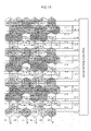
- Fig. 2 illustrates an electrical configuration of a radiation detector of an imaging apparatus according to the present exemplary embodiment.
- a radiation detection element 10 of the radiation detector 42 illustrated in Fig 2 is configured with plural pixels 20 that have hexagonal shaped pixel regions arrayed adjacently in a two dimensional honeycomb pattern, so as to configure a region that is substantially rectangular shaped overall.
- Each of the pixels 20 is configured including a sensor portion 103 that receives radiation (X-rays) that has been irradiated and generates charges, a charge storage capacitor 5 that accumulates the charges that have been generated in the sensor portion 103, and two thin film transistors (hereinbelow referred to as TFT switches) 4a, 4b for reading the charges accumulated in the charge storage capacitors 5.
- the radiation detector 42 is accordingly a direct-conversion-type radiation detector that employs a radiation - charge conversion material, such as amorphous selenium in a photoelectric conversion layer, to absorb radiation and convert it into charges, as described later.
- Disposing the pixels 20 in a honeycomb pattern means that the pixels 20 having hexagonal shaped pixel regions of the same size as each other are arrayed with plural first pixel rows arrayed in a row direction (the horizontal direction in Fig. 2 ), and plural second pixel rows, configured by pixels 20 having hexagonal shaped pixel regions of the same size as the first pixel row pixels 20 arrayed in the row direction.
- the first pixel rows and the second pixel rows are arrayed alternately along a direction that intersects with a column direction (the vertical direction in Fig. 2 ).
- the pixels 20 of the second pixel rows are disposed aligned between adjacent pixels of the first pixel rows, such that the pixels 20 of the second pixel rows are displaced in the row direction from the pixels 20 in the first pixel rows by 1/2 the array pitch of the first pixel row pixels 20.
- the radiation detector 42 includes first scan lines G1-0 to G1-7 (also referred to as first scan lines G1, further also referred collectively to as scan lines G when referred together with the below mentioned scan lines) disposed corresponding to each of the pixel rows.
- the gate electrodes of the TFT switches 4a provided in each of the pixels 20 are connected to the first scan lines G1, and the TFT switches 4a are ON/OFF controlled according to signals flowing in the first scan lines G1.
- the radiation detector 42 is also equipped with second scan lines G2-0 to G2-3 (also referred to as second scan lines G2) disposed corresponding to each of the pixel rows equipped with the first scan lines G1-0 to G 1-3, and with third scan lines G3-0 to G3-3 (also referred to as third scan lines G3) disposed corresponding to each of the pixel rows equipped with the first scan lines G1-4 to G1-7.
- the gate electrodes of the TFT switches 4b provided in pixels configuring pixel groups are connected to the second scan lines G2 and the third scan lines G3, and the TFT switches 4b are ON/OFF controlled according to signals flowing in the second scan lines G2 and the third scan lines G3.
- the radiation detection element 10 of the radiation detector 42 is configured with pixel rows disposed with one of the first scan lines G1 and one of the second scan lines G2, and with pixel rows disposed with one of the first scan lines G1 and one of the third scan lines G3.
- the radiation detector 42 is also equipped with plural data lines D1 to D6 (also referred to collectively as data lines D) for reading the charges that were generated in the sensor portions 103 in each of the pixels and accumulated in the respective charge storage capacitors 5, and with common ground lines 30.
- Fig. 2 illustrates a configuration in which the second scan lines G2-0 to G2-3 and the third scan lines G3-0 to G3-3 respectively branch from a single line extending out from a scan signal control section 35 into four lines
- configuration may be made such that each of the second scan lines G2-0 to G2-3 and the third scan lines G3-0 to G3-3 extend out separately from the scan signal control section 35, and the second scan lines G2-0 to G2-3 are driven simultaneously and then the third scan lines G3-0 to G3-3 are driven simultaneously.
- Configuration may also be made with a second scan signal control section provided separately to the scan signal control section 35, such that 1 line extending out from the second scan signal control section branches into 4. Further, configuration made such that there are separate individual second scan lines G2-0 to G2-3 and third scan lines G3-0 to G3-3 extending out from the second scan signal control section provided separately to the scan signal control section 35, with the second scan lines G2-0 to G2-3 driven simultaneously and the third scan lines G3-0 to G3-3 driven simultaneously. Note that, although the drive load is large in a configuration with a single line branching into 4, there is the advantage that a second scan signal control section does not have to be provided, and a configuration respectively connected to a separate second scan signal control section has the advantage that the drive load is small.
- Fig. 2 for ease of explanation and illustration, an example is shown of a configuration laid out with 14 scan lines G and 6 data lines D.
- m ⁇ n individual pixels 20 respectively disposed in the row direction and the column direction (wherein m and n are positive integers)
- the scan lines G1 to G3 are disposed so as to intersect with the data lines D and the common ground lines 30.
- the data lines D are laid out along the peripheral edges of the pixels 20 with hexagonal shaped pixel regions in a zigzag pattern (so as to meander) so as to bypass these pixels 20. Namely, the data lines D extend in the column direction while running along 3 adjoining sides out of the peripheral edges (6 sides) of each of the individual pixels 20.
- the common ground lines 30 are also disposed in a zigzag pattern (so as to meaner) to match the data lines D, there is the possibility of various issues such as, for example, locations where the separation between TFT switches 4a, 4b in the pixels 20 is narrow occurring at portions meandering to the left or right, common ground lines 30 and TFT switches 4a and 4b colliding, and/or the capacity between data lines D and the common ground lines 30 increasing.
- the radiation detector 42 of the present exemplary embodiment is therefore, as illustrated in Fig. 2 , laid out with the plural scan lines G1 to G3 running along a row direction (the horizontal direction in Fig.
- the TFT switches 4a, 4b etc., inside each of the pixels 20, are also laid out towards one side so as to secure specific free spaces in each of the pixels 20, and the common ground lines 30 are laid out so as to pass through these free spaces.
- the TFT switches 4a, 4b etc. are disposed in regions surrounded by a line segment that partitions each of the pixels 20 in half along the column direction (the vertical direction in Fig. 2 ) and 3 sides at the periphery of each of the pixels 20 where the data lines D are provided.
- the TFT switches 4a, 4b etc. are laid out in the region of the right hand half for pixels in a given pixel row
- the TFT switches 4a, 4b etc. are laid out in the region of the left hand half for pixels 20 in the pixel row positioned above and below the given pixel row in the column direction.
- the common ground lines 30 may be disposed as straight lines intersecting with the scan lines G 1 to G3 between the plural data lines D 1 to D6 and without intersecting with the data lines D1 to D6.
- the storage capacitor lower electrodes 11 of the charge storage capacitors 5 of each of the pixels 20 can be mutually connected together by the shortest common ground lines 30, in a direct-conversion-type radiographic image detector 42.
- the need to make the common ground lines 30 meander to match the data lines D is also eliminated. Since there is also no intersection between the data lines D and the common ground lines 30, an increase in noise caused by such effects as induction in the data lines, and an increase in the interline capacitance between the data lines D and the common ground lines 30, may not occur.
- the resolution of the radiation detection device can also be raised without the straight line common ground lines 30 impeding higher definition of pixels 20 of the radiation detection element 10. Moreover, in the manufacturing processes for the radiation detection element 10, a drop in manufacturing yield of the radiation detection device due to interline pitch between the data lines D and the common ground lines 30 narrower, may be avoided. Note that, disposing the common ground lines 30 as straight lines means that a straight state is maintained within a range obtainable while allowing for manufacturing error in manufacturing processes of the radiation element 10.
- OFF signals are output to the first scan lines G1 and each of the TFT switches 4a is switched OFF, and OFF signals are output to the second scan lines G2 and the third scan lines G3, switching each of the TFT switches 4b OFF.
- the charges generated in a semiconductor layer are accordingly accumulated in each of the charge storage capacitors 5.
- ON signals are output in sequence one line at a time to the first scan lines G1-0 to G1-7, switching the TFT switches 4a in each of the pixels 20 ON.
- ON signals are output simultaneously to the second scan lines G2-0 to G2-3 and then ON signals are output simultaneously to the third scan lines G3-0 to G3-3, switching ON the TFT switches 4b of plural pixels in pixel groups.
- the charges accumulated in each of the charge storage capacitors 5 are thereby read as electrical signals, and a radiographic image is obtained by converting the read electrical signals into digital data.
- a signal processing section 25 includes signal detectors (not shown in the drawings) that detect charges flowing out of each of the data lines D 1 to D6 as electrical signals, and subjects the detected electrical signals to specific processing.
- the signal processing section 25 also outputs control signals expressing a signal detection timing to the signal detectors and control signals expressing a scan signal output timing to the scan signal control section 35.
- the scan signal control section 35 outputs signals to the first scan lines G1-0 to G1-7 for switching the TFT switches 4a ON/OFF.
- the scan signal control section 35 also outputs signals to the second scan lines G2-0 to G2-3 and the third scan lines G3-0 to G3-3 for switching the TFT switches 4b ON/OFF.
- the charge signals transmitted by the individual data lines D1 to D3 are amplified in the signal processing section 25 by amplifiers, and are held in sample-and-hold circuits (not shown in the drawings).
- the charge signals held by the individual sample-and-hold circuits are input in sequence to a multiplexer (not shown in the drawings), and then converted into digital image data by an A/D converter.
- an image memory 90 is connected to the signal processing section 25, and the digital image data output from the A/D converter is stored in sequence in the image memory 90.
- the image memory 90 for example, stores digital image data for plural frames worth of imaged radiographic images.
- Fig. 3 illustrates a partial cross-sectional view including a single pixel of a radiation detection element 10 of a radiation detector 42 according to the first exemplary embodiment.
- the radiation detection element 10 of the radiation detector 42 is, as shown in Fig. 3 , a structure in which gate electrodes 2, scan lines G (not shown in Fig. 3 ) and storage capacitor lower electrodes 14 are formed as a gate wiring layer on an insulating substrate 1.
- a wiring layer also referred to as a source wiring layer
- source electrodes 9, drain electrodes 13, data lines D, and storage capacitor upper electrodes 16 is formed using a layered film of, for example, Al or Cu, or mainly ofAl or Cu.
- An impurity doped semiconductor layer (not shown in the drawings) such as impurity doped amorphous silicon is formed between semiconductor active layers 8 and the source electrodes 9, and the drain electrodes 13. Note that the source electrodes 9 and the drain electrodes 13 are reversed in the TFT switches 4a, 4b according to the polarity of the charges collected and accumulated by a lower electrode 11.
- the gate wiring layer for the gate electrodes 2 is formed using a layered film of, for example, Al or Cu, or mainly of Al or Cu.
- An insulating film 15A is formed on one face on the gate wiring layer, and the locations of the insulating film 15A above the gate electrodes 2 act as gate insulation films for the TFT switches 4a, 4b.
- the insulating film 15A is, for example, configured from SiNx, and is formed, for example, by a Chemical Vapor Deposition (CVD) film forming process.
- the semiconductor active layers 8 are formed with island shapes on the insulation film 15A above each of the gate electrodes 2.
- the semiconductor active layers 8 are channel portions of the TFT switches 4a, 4b and are, for example, formed from an amorphous silicon film.
- the source electrodes 9 and the drain electrodes 13 are formed in a layer above the gate electrodes 2.
- the data lines D are also formed together with the source electrodes 9 and the drain electrodes 13.
- the storage capacitor upper electrodes 16 are also formed at positions on the insulating film 15A corresponding to the storage capacitor lower electrodes 14.
- the drain electrodes 13 are connected to the storage capacitor upper electrodes 16.
- the data lines D are disposed running along the peripheral edges of the pixels 20 in the manner described above, bent so as to bypass between one pixel and an adjacent pixel.
- the data lines 3 are connected to the source electrodes 9 formed to the pixels 20 in each of the pixel rows.
- a TFT protection layer 15B is formed over substantially the whole surface (substantially all regions) of the region where the pixels are provided on the substrate 1 so as to cover the source wiring layer.
- the TFT protection layer 15B is formed, for example, from a material such as SiN x by, for example, a CVD film forming method.
- a coated interlayer insulating film 12 is then formed on the TFT protection layer 15B.
- inter-metal capacitance between metal disposed in the layers above the interlayer insulating film 12 and below the interlayer insulating film 12 is suppressed to be small by the interlayer insulating film 12.
- the materials of the interlayer insulating film 12 also function as a flattening film, exhibiting an effect of flattening out steps in the layers below.
- contact holes 17 are formed in the interlayer insulating film 12 and the TFT protection layer 15B at locations corresponding to the storage capacitor upper electrodes 16.
- Lower electrodes 11 of each of the sensor portions 103 are formed on the interlayer insulating film 12 for each of the pixels 20, so as to cover the pixel region while also filling each of the contact holes 17.
- the lower electrodes 11 are formed from an amorphous transparent conducting oxide film (ITO) and are connected to the storage capacitor upper electrodes 16 through the contact holes 17.
- ITO amorphous transparent conducting oxide film
- the lower electrodes 11 and the TFT switches 4a, 4b are electrically connected through the storage capacitor upper electrodes 16.
- the lower electrodes 11 are preferably formed in shapes to match the shapes of the pixel regions of the pixels 20, there is no limitation thereto.
- the lower electrodes 11 are preferably formed with slightly smaller regular hexagonal shapes so as not to touch the lower electrodes of adjacent pixels.
- the lower electrodes 11 are preferably formed in slightly smaller hexagonal shapes. As long as the pixel placement of the lower electrodes configures a hexagonal lattice, configuration may be made with beveled corner hexagonal shaped or square shaped lower electrodes 11.
- a photoelectric conversion layer 6 is uniformly formed on the lower electrodes 11 over substantially the entire surface of the pixel region where the pixels 20 are provided on the substrate 1.
- the photoelectric conversion layer 6 generates charges (electrons-holes) internally on irradiation with radiation such as X-rays.
- the photoelectric conversion layer 6 has electrical conduction properties and is employed to convert image data from radiation into charge data.
- the photoelectric conversion layer 6 may be formed from amorphous selenium (a-Se) having selenium as the main component and a film thickness of 100 ⁇ m to 1000 ⁇ m. Note that, the main component means contained at a ratio of 50% of more.
- An upper electrode 7 is formed on the photoelectric conversion layer 6.
- the upper electrode 7 is connected to a bias power source (not shown in the drawings) and supplies a bias voltage (for example several kV) from the bias power source.
- the plural scan lines G1, G2, G3, the data lines 3, the common ground lines 30 and the TFT switches 4a, 4b are disposed at a lower layer side of the sensor portions 103 configured by the photoelectric conversion layer 6.
- the gate electrodes 2 In the radiation detection element 10 of the radiation detector 42, the gate electrodes 2, the first to the third scan lines G1 to G3 and the storage capacitor lower electrodes 14 are formed as the gate wiring layer on the substrate 1, and the common ground lines 30 are formed on the substrate 1, for example in the same metal layer as the storage capacitor lower electrodes 14.
- Charges are generated in the photoelectric conversion layer 6 when X-rays are irradiated onto the photoelectric conversion layer 6 in a state in which a bias voltage is being applied across the upper electrode 7 and the storage capacitor lower electrodes 14.
- the photoelectric conversion layer 6 and the charge storage capacitors 5 are electrically connected in series, and so electrons generated in the photoelectric conversion layer 6 migrate to the + (plus) electrode side and holes migrate to the - (minus) electrode side.
- OFF signals (for example, 0V) are output from the scan signal control section 35 to the first scan lines G1-0 to G1-7, the second scan lines G2-0 to G2-3 and the third scan lines G3-0 to G3-3, applying a negative bias to the gate electrodes of the TFT switches 4a, 4b.
- Each of the TFT switches 4a, 4b are thereby maintained in an OFF state.
- electrons generated in the photoelectric conversion layer 6 are collected by the lower electrodes 11, and are accumulated in the charge storage capacitors 5.
- the photoelectric conversion layer 6 generates a charge amount according to the amount of radiation irradiated, and so the charges according to image data carried by the radiation are accumulated in the charge storage capacitors 5 of each of the pixels.
- the charge storage capacitors 5 need to be given a larger capacitance than the capacitance formed by the photoelectric conversion layer 6 due to the voltage of several kV referred to above being applied across the upper electrode 7 and the storage capacitor lower electrodes 14.
- the radiation detector 42 performs in a still imaging mode or a video imaging mode according to instruction from the image processing apparatus 50 as described above.
- the signal processing section 25 controls the scan signal control section 35 such that scan signals are output from the second scan lines G2-0 to G2-3 and the third scan lines G3-0 to G3-3 for switching OFF the TFT switches 4b in each of the pixels 20.
- the signal processing section 25 also controls the scan signal control section 35 to apply ON signals for example with a voltage of +10 V to 20 V in sequence from the first scan lines G1-0 to G1-7 to the gates of each of the TFT switches 4a in order to switch ON the TFT switches 4a in each of the pixels 20.
- the TFT switches 4a in each of the pixels 20 are thereby switched to an ON state in sequence for each of the pixel rows, charges are read from the sensor portions 103 by the TFT switches 4a, and signals corresponding to these charges are output to the data lines D.
- the 4 pixels P0 to P3 form a pixel group PG0
- the 4 pixels P4 to P7 form a pixel group PG1
- the 4 pixels P8 to P11 form a pixel group PG2
- the 4 pixels P12 to P15 form a pixel group PG3
- the 4 pixels P16 to P19 form a pixel group PG4.
- the gate electrodes of each of the TFT switches 4b in, the pixel P0 of the pixel group PG0, the pixel P4 of the pixel group PG1 and the pixel P8 of the pixel group PG2, are connected to the second scan line G2-0.
- the gate electrodes of each of the TFT switches 4b in, the pixels P1 to P3 of the pixel group PG0, the pixels P5 to P7 of the pixel group PG1, and the pixels P9 to P11 of the pixel group PG2, are connected to the second scan line G2-1.
- the gate electrodes of each of the TFT switches 4b in, the pixel P12 of the pixel group PG3, and the pixel P16 of the pixel group PG4, are connected to the second scan line G2-2, and the gate electrodes of each of the TFT switches 4b in, the pixels P13 to P15 of the pixel group PG3, and the pixels P 17 to P 19 of the pixel group PG4, are connected to the second scan line G2-3.
- connections of the pixel groups (PG5 to PG9) configured by the pixels P20 to P23, the pixels P24 to P27, the pixels P28 to P31, the pixels P32 to P35, and the pixels P36 to P39, and the third scan lines G3-0 to G3-3, are connected in a similar pattern to the connections described above of the pixel groups PG0 to PG4 to the second scan lines G2-0 to G2-3.
- the signal processing section 25 controls the scan signal control section 35 so as to switch OFF the TFT switches 4a of each of the pixels 20, and outputs OFF signals from the first scan lines G1-0 to G 1-7 to each of the gate electrodes of the TFT switches 4a of each of the pixels 20.
- the signal processing section 25 also controls the scan signal control section 35 to simultaneously drive the second scan lines G2-0 to G2-3 to output scan signals (ON signals).
- the TFT switches 4b of all the pixels 20 in the pixel groups PG0 to PG4 are switched ON when the ON signal is output simultaneously to the second scan lines G2-0 to G2-3.
- the charges accumulated in each of the charge storage capacitors 5 of the four individual pixels P0 to P3 of the pixel group PG0 are combined and the combined charge signal is output to the data line D2.
- a combined charge signal of the four individual pixels P12 to P15 of the pixel group PG3 is output to the data line D3
- a combined charge signal of the four individual pixels P4 to P7 of the pixel group PG1 is output to the data line D4
- a combined charge signal of the four individual pixels P16 to P 19 of the pixel group PG4 is output to the data line D5
- a combined charge signal of the four individual pixels P8 to P11 of the pixel group PG2 is output to the data line D6.
- the signal processing section 25 controls the scan signal control section 35 to simultaneously drive the third scan lines G3-0 to G3-3 and output scan signals (ON signals) thereto.
- the TFT switches 4b of all the pixels 20 in the pixel groups PG5 to PG9 are switched ON when the ON signals are simultaneously output to the third scan lines G3-0 to G3-3.
- a combined charge signal from the four pixels of the pixel group PG5 is output to the data line D2
- a combined charge signal of the four pixels of the pixel group PG8 is output to the data line D3
- a combined charge signal of the four pixels of the pixel group PG6 is output to the data line D4
- a combined charge signal of the four pixels of the pixel group PG9 is output to the data line D5
- a combined charge signal of the four pixels of the pixel group PG7 is output to the data line D6.
- the binning scan lines G (G2 and G3) are split into plural groups (G2 and G3), and scan signals for the TFT switch 4b are sent to the scan lines G belonging to each of the groups at timings shifted for each of the groups.
- the charge signals corresponding to the combined charge amounts read from different pixel groups are not transmitted through the same data lines D.
- Fig. 4 illustrates a layout of pixels and pixel groups subject to binning in the video imaging mode described above. Note that, in Fig. 4 , the shading pattern has been changed for each of the pixels in adjacent pixel groups to make it easier to discriminate the respective pixel groups from each other.
- the radiation detection element 10 of the radiation detector 42 specifies pixel groups A, B, C, D, E, F, G formed from 4 adjacent pixels as described above.
- Each of the pixel groups are configured from 4 pixels, configured by a first pixel out of the plural pixels, a second pixel and a third pixel that are each mutually adjacent to each other in a row adjacent to the first pixel row, and a fourth pixel that is in a row adjacent to the second pixel and third pixel row.
- the 4 pixels are disposed such that two adjoining sides of the first pixel and two adjoining sides of the fourth pixel are respectively adjacent to one side of the second pixel and the third pixel, respectively, so as to lie between the second pixel and the third pixel.
- each of the pixel groups can be defined as being a combination of 4 pixels configured by 3 pixels, disposed such that two adjoining sides of each of the pixels are respectively mutually adjacent to one side of the remaining 2 pixels, and by 1 pixel, disposed such that two adjoining sides are respectively mutually adjacent to one side of 2 pixels out of the 3 pixels.
- the combination of 4 pixels may also be described as being a combination of 4 pixels formed from 2 pairs of mutually adjacent pixels disposed alongside each other, with 2 adjoining sides of 1 pixel from a first pair disposed mutually adjacent to 1 side of each of the 2 pixels in the other pair respectively.
- the signal processing section 25 switches ON the TFT switches 4a in each of the pixels 20 of the radiation detector 42, reads out the charges from each of the pixels, and outputs signals corresponding to the charges to the data lines D. Since pixels with hexagonal shaped pixel regions are employed as the individual pixels in the radiation detection element 10 of the radiation detector 42 of the present exemplary embodiment, a high resolution may be secured in each of the horizontal, vertical and diagonal directions.
- the 4 pixels act as a single pixel, and binning is performed to combine 4 pixels worth of charges.
- the positions of the center of gravity for each of the pixel groups A, B, C, D, E, F, G formed from 4 pixels are positioned as black dots indicated respectively as a, b, c, d, e, f, g.
- a regular hexagonal shape is formed by connecting the centers of gravity of other pixel groups a - b - e - g - f - c - a, with the center of gravity d of the pixel group D at the center. It can also be seen that the inter center of gravity distances of these pixel groups, namely in the 6 directions d to a, d to b, d to e, d to g, d to f, and d to c, are all the same as each other.
- each of the pixels 20 may be a hexagonal shape, even resolution may be secured in each of the horizontal, vertical and diagonal directions, before binning.
- a regular hexagonal shape is also formed by connecting together the centers of gravity of the pixel groups, even resolution may also be secured in each of the horizontal, vertical and diagonal directions, after binning.
- each of the pixels in each of the pixel groups are determined such that plural hexagonal shaped regions are arrayed in a honeycomb pattern.
- the center of gravity a, b, c, d, e, f, g of each of the regions surrounded by the outlines of the pixel groups A, B, C, D, E, F, G each of the hexagonal shaped regions are formed including, 1 center of gravity d at the inside, and hexagonal shaped region formed by the line segments connecting the 6 individual centers of gravity a, b, e, g, f, c present at the periphery of the center of gravity d.
- the present exemplary embodiment may suppress unevenness in each of the horizontal, vertical and diagonal directions of the pixel positions (the center of gravity positions of the pixel groups) after binning, and may enable even resolution to be secured in each of the respective directions, similarly to in an image before binning.
- processing may be performed with a similar algorithm when performing pixel density conversion after binning, to when performing pixel density conversion without binning.
- the algorithm for pixel density conversion processing may be commonly employed both before and after binning, without preparing another separate algorithm for pixel density conversion processing after binning.
- a program for performing pixel density conversion on image data expressing radiographic images detected by the radiation detector 42 is stored on the ROM 62 and/or the HDD 66.
- the image data output to the display device 80 is accordingly image data after performing pixel density conversion.
- Fig. 5 is a flow chart showing an example of an imaging processing sequence executed in the image processing apparatus 50 of a radiographic imaging system 100 according to the present exemplary embodiment.
- the amount of radiation irradiated from the radiation irradiation section 24 is detected in the radiation detector 42 of the imaging apparatus 41.
- determination is made as to whether or not the radiation amount has exceeded a predetermined threshold value. When determined that the amount of radiation irradiated has exceeded the threshold value, it is determined that sufficient sensitively can be obtained for imaging (image S/N will be sufficient).
- step S104 ON signals are output in sequence one line at a time to the first scan lines G 1-0 to G1-7, scan signals are transmitting to the respective plural pixels 20, and normal processing to read the charge signals accumulated in the storage capacitors 5 of each of the pixels 20 is performed (still imaging mode).
- step S106 when determined at step S102 that the amount of radiation irradiated is the threshold value or lower, it is considered that the S/N for the image obtained would be insufficient, processing proceeds to step S106, and processing is performed to image a high S/N image.
- the pixel groups A, B, C, D, E etc. formed from specific 4 pixels are set as described above.
- scan signals ON signals
- step S108 scan signals (ON signals) are output by the scan signal control section 35 to the second scan lines G2 and the third scan lines G3 to switch on the TFT switches 4b of each of the pixels disposed in the pixel groups A, B, C, D, E etc., and binning processing is performed to treat the 4 pixels of each of the pixel groups as a single pixel.
- the amount of radiation irradiated is the threshold value or lower, a radiographic image with good S/N is obtained by processing to combine the charges of plural pixels (binning) due to the consideration that otherwise there would be insufficient imaging sensitivity.
- process is performed in consideration of the S/N of the radiographic image that will be obtained according to the amount of radiation irradiated.
- configuration may be made so as to switch between normal processing without binning and processing with binning according to instruction for the still imaging mode or the video imaging mode, irrespective of the amount of radiation irradiated.
- Configuration may be made to perform the above switching according to the required resolution for imaging.
- scan lines G1 are disposed for each pixel row connected to the TFT switches 4a in each of the pixels 20 of plural pixels 20 having hexagonal shaped pixel regions arrayed in a honeycomb pattern, and for the predetermined plural pixel groups each configured from 4 pixels, scan lines G2 and G3 are disposed for each pixel row for performing binning processing by reading and combining 4 pixels worth of charges at the same timing.
- the binning processing scan lines G2 and G3 then output a signal to simultaneously switch ON the TFT switches 4b in the pixels of specific plural pixel groups, and configuration is made such that the charge signals for the combined charges of each of the respective plural pixel groups flow in the separate respective data lines.
- imaging may be performed at 4 times the rate in comparison to when reading the charge signals from the individual pixels without binning processing.
- the S/N may be raised by increasing the amount of charge collected, may enable application to a video imaging mode demanding a high frame rate as well as application to low sensitivity images generated by irradiating a small amount of radiation.
- the pixel groups configured from 4 pixels are treated as a single pixel, the charges are simultaneously read from plural pixel groups, and binning process is performed to combine the charges accumulated in each of the pixels configuring these pixel groups.
- a frame rate that is 4 times (a frame duration of 1/4) that of the still imaging mode can be achieved for reading charges successively from each pixel row.
- combination of 4 pixels in each of the pixel groups is determined such that plural hexagonal shaped regions are arrayed in a honeycomb pattern.
- Each of the plural hexagonal shaped regions are formed by including inside 1 center of gravity of the region surrounded by the outlines of the pixel groups and the line segments connecting the 6 individual centers of gravity present at the periphery of the 1 center of gravity. Accordingly, unevenness of the pixel positions (the center of gravity position when plural pixels are treated a single pixel clump) after binning in each of the horizontal, vertical and diagonal directions may be suppressed, and even resolution may be secured in each of the respective directions, similarly to in an image before binning.
- a common integrated circuit may be employed for pixel density conversion before and after binning. Further, processing can be performed employing the same algorithm even in processing by programmable devices such as a FPGA and software rather than with an IC with fixed circuit.
- radiographic imaging system 100 is similar to the radiographic imaging system 100 according to the first exemplary embodiment illustrated in Fig. 1 , and so illustration and further explanation will be omitted.
- Fig. 6 illustrates an electrical configuration of a radiation detector 142 in an imaging apparatus 41 of a radiographic imaging system 100 according to the present exemplary embodiment.
- a radiation detection element 110 of a radiation detector 142 illustrated in Fig. 6 is configured with plural pixels 20 that have hexagonal shaped pixel regions arrayed adjacently in a two dimensional honeycomb pattern, such that the pixels 20 arrayed in a honeycomb pattern configure a rectangular shaped pixel region.
- Each of the pixels 20 is configured similarly to in the radiation detection element 10 of the radiation detector 42 illustrated in Fig 2 .
- the radiation detector 142 includes: fourth scan lines G4-1 to G4-4 (also referred to as fourth scan lines G4) connected to the gate electrodes of the TFT switches 4a provided in each of the pixels 20 for ON/OFF controlling the TFT switches 4a; fifth scan lines G5-1, G5-2 (also referred to as fifth scan lines G5) connected to the gate electrodes of the TFT switches 4b for ON/OFF controlling the TFT switches 4b, plural data lines D1 to D3 (also referred to as data lines D) that read charges generated in sensor portions 103 and accumulated in charge storage capacitors 5; and common ground lines 30.
- fourth scan lines G4-1 to G4-4 also referred to as fourth scan lines G4
- fifth scan lines G5-1, G5-2 also referred to as fifth scan lines G5
- plural data lines D1 to D3 also referred to as data lines D
- Fig. 6 for ease of explanation and illustration, an example is shown of a configuration laid out with 4 lines of the fourth scan lines G4, 2 lines of the fifth scan lines G5, 3 lines of the data lines D, and 3 lines of the common ground lines 30.
- the number of the fifth scan lines G5 is half the number of the fourth scan lines G4, namely m/2 lines are provided.
- the radiation detection element 110 of the radiation detector 142 employs a radiation - charge conversion material such as amorphous selenium, as described later, in a configuration that directly converts radiation to charges.
- the common lines (not shown in the drawings) are connected to the sensor portions 103 of each of the pixels 20, in a configuration in which a bias voltage from a power source (not shown in the drawings) is applied through the common lines.
- the scan lines G4, G5 are disposed so as to intersect with the data lines D and the common ground lines 30.
- the data lines D are laid out along the peripheral edges of the pixels 20 with hexagonal shaped pixel regions in a zigzag pattern (so as to meander) so as to bypass these pixels 20. Namely, the data lines D extend in the column direction while running along 3 adjoining sides out of the peripheral edges (6 sides) of each of the individual pixels 20.
- the common ground lines 30 are also disposed in a zigzag pattern (so as to meaner) so as to keep away from the TFT switches 4a, 4b of each of the pixels 20.
- the gate electrodes of the TFT switches 4a are connected to the fourth scan lines G4, and the gate electrodes of the TFT switches 4b are connected to the fifth scan lines G5.
- One or other of the drain electrodes or the source electrodes of the TFT switches 4a, 4b are connected to one electrode of the charge storage capacitors 5, and the other of the drain electrodes or the source electrodes are connected to the data lines D.
- OFF signals are output to the fourth scan lines G4 and each of the TFT switches 4a is switched OFF, and OFF signals are output to the fifth scan lines G5, switching each of the TFT switches 4b OFF. Accordingly, the charges generated in a semiconductor layer are accumulated in each of the charge storage capacitors 5.
- ON signals are output in sequence one line at a time to the fourth scan lines G4, switching the TFT switches 4a in each of the pixels 20 ON.
- ON signals are output in sequence one line at a time to the fifth scan lines G5, switching ON the TFT switches 4b of plural pixels in pixel groups.
- the charges accumulated in each of the charge storage capacitors 5 are thereby read as electrical signals, and a radiographic image is obtained by converting the read electrical signals into digital data.
- a signal processing section 125 includes signal detectors (not shown in the drawings) that detect charges flowing out of each of the data lines D 1 to D3 as electrical signals, and subjects the detected electrical signals to specific processing.
- the signal processing section 125 also outputs control signals expressing a signal detection timing and control signals expressing a scan signal output timing respectively to each of the signal detectors and scan signal control sections 35a, 35b.
- the scan signal control section 35a on receipt of the control signals from the signal processing section 125, the scan signal control section 35a outputs scan signals to the fourth scan lines G4-1 to G4-4 for switching the TFT switches 4a ON/OFF.
- the scan signal control section 35b also outputs scan signals to the fifth scan lines G5-1, G5-2 for switching the TFT switches 4b ON/OFF.
- the charge signals transmitted by the individual data lines D1 to D3 are amplified in the signal processing section 125 by amplifiers and held in sample-and-hold circuits, not shown in the drawings.
- the charge signals held by the individual sample-and-hold circuits are input in sequence to a multiplexer (not shown in the drawings), and then converted into digital image data by an A/D converter.
- the digital image data output from the A/D converter is, for example, stored in sequence in the image memory 90 as digital image data for plural frames worth of imaged radiographic images.
- OFF signals for example, 0V
- OFF signals are output from the scan signal control sections 35a, 35b to the fourth scan lines G4-1 to G4-4 and the fifth scan lines G5-1, G5-2, applying a negative bias to the gate electrodes of the TFT switches 4a, 4b.
- Each of the TFT switches 4a, 4b are thereby maintained in an OFF state.
- the radiation detector 142 performs in a still imaging mode or a video imaging mode, according to instruction from an image processing apparatus.
- the signal processing section 125 controls the scan signal control sections 35b such that scan signals are output from the fifth scan lines G5-1, G5-2 for switching OFF the TFT switches 4b in each of the pixels 20.
- the signal processing section 125 also controls the scan signal control sections 35a to apply ON signals for example with a voltage of +10 V to 20 V in sequence from the fourth scan lines G4-1 to G4-4 to the gates of each of the TFT switches 4a, in order to switch ON the TFT switches 4a in each of the pixels 20.
- the TFT switches 4a in each of the pixels 20 are thereby switched to an ON state in sequence for each of the pixel rows, charges are read from the sensor portions 103 by the TFT switches 4a, and signals corresponding to these charges are output to the data lines D.
- charge signals flow corresponding to each of the pixels 20 in each of the pixel rows.
- Image data expressing an image representing radiation irradiated onto the radiation detection element 110 of the radiation detector 142 can accordingly be obtained.
- the signal processing section 125 the charge signals are then converted into digital signals, and a radiographic image based on the image data corresponding to the charge signals is generated.
- the gate electrodes of each of the TFT switches 4b in the 4 pixels P2, P3, P5, P6 surrounded by a dashed line are connected to the fifth scan line G5-1.
- the gate electrodes of each of the TFT switches 4b in the 4 pixels P8, P9, P11, P12 surrounded by a dashed line are connected to the fifth scan line G5-2.
- the pixels P2, P3, P5, P6 are referred to together as pixel group PG1
- the pixels P8, P9, P11, P12 are referred to together as pixel group PG2.
- the pixel groups in the radiation detection element 110 while omitted from illustration in Fig. 6 , are also configured by plural other pixel groups each formed from 4 specific pixels other than the pixel groups PG1, PG2 (see for example Fig. 7 ).
- the signal processing section 125 controls the scan signal control section 35a so as to switch OFF the TFT switches 4a of each of the pixels 20, and outputs OFF signals from the fourth scan lines G4-1 to G4-4 to each of the gate electrodes of the TFT switches 4a of each of the pixels 20.
- the signal processing section 125 also controls the scan signal control section 35b to sequentially drive the fifth scan lines G5-1, G5-2 to output scan signals (ON signals). Namely, the TFT switches 4b of the four individual pixels P2, P3, P5, P6 of pixel group PG1 are switched ON when the ON signal is output from the fifth scan line G5-1. As a result a combined charge signal summing the charges accumulated in each of the charge storage capacitors 5 of the four individual pixels P2, P3, P5, P6 is output to the data line D2. Then, the TFT switches 4b of the four individual pixels P8, P9, P 11, P12 of pixel group PG2 are switched ON when the ON signal is output from the fifth scan line G5-2. In this case a combined charge signal summing the charges accumulated in the four individual pixels P8, P9, P11, P 12 is output to the data line D 1.
- Fig. 7 illustrates a layout of pixels and pixel groups subject to binning in the video imaging mode described above. Note that in Fig. 7 the shading pattern is changed in each of the pixels in adjacent pixel groups to make it easier to discriminate the respective pixel groups from each other.
- the radiation detection element 110 of the radiation detector 142 specifies pixel groups A, B, C, D, E, F, G, H formed from 4 adjacent pixels as described above.
- the pixel group A is configured from a total of 4 pixels (the 4 pixels applied with a vertical line pattern), these being 2 adjacent pixels out of the pixels 20 in a first pixel row that is along the row direction appended with 20a in Fig. 7 , and 2 mutually adjacent pixels out of the pixels 20 in a second pixel row positioned in the row below the first pixel row along the row direction appended with 20b in Fig. 7 , displaced by 1/2 the array pitch of the first pixel row to the first 2 pixels.
- Each of the pixel groups can be defined as being a combination of 4 pixels configured by 3 pixels disposed such that two adjoining sides of each of the pixels are respectively mutually adjacent to one side of the remaining 2 pixels, and by 1 pixel disposed such that two adjoining sides are respectively mutually adjacent to one side of 2 pixels out of the 3 pixels.
- the combination of 4 pixels may also be described as being a combination of 4 pixels formed from 2 pairs of mutually adjacent pixels disposed alongside each other, with 2 adjoining sides of 1 pixel from a first pair respectively disposed mutually adjacent to 1 side of each of the 2 pixels in the other pair.
- the signal processing section 125 switches ON the TFT switches 4a in each of the pixels 20 of the radiation detector 142, reads the charges from each of the pixels, and outputs signals corresponding to the charges to the data lines D. Since pixels with hexagonal shaped pixel regions are employed as the individual pixels in the radiation detection element 110 of the radiation detector 142 a high resolution may be secured in each of the horizontal, vertical and diagonal directions.
- the 4 pixels act as a single pixel, and binning is performed to combine 4 pixels worth of charges.
- the positions of the center of gravity for each of the pixel groups A, B, C, D, E, F, G, H formed from 4 pixels are positioned at the black dots indicated respectively as a, b, c, d, e, f, g, h.
- a regular hexagonal shape is formed by connecting the centers of gravity a - c-g - h - e - b - a, with the center of gravity d of the pixel group D at the center. It can also be seen that the inter-center of gravity distances of these pixel groups, namely in the 6 directions d to a, d to c, d to g, d to h, d to e, d to b, are all the same as each other.
- each of the pixels in each of the pixel groups are determined such that plural hexagonal shaped regions are arrayed in a honeycomb pattern.
- the centers of gravity a, b, c, d, e, g, h of each of the regions surrounded by the outlines of the pixel groups A, B, C, D, E, F, G, H each of the hexagonal shaped regions are formed including, 1 center of gravity d at the inside, and hexagonal shaped regions formed by the line segments connecting the 6 individual centers of gravity a, c, g, h, e, b present at the periphery of the center of gravity d.
- the present exemplary embodiment may suppress unevenness in each of the horizontal, vertical and diagonal directions of the pixel positions (the center of gravity positions of the pixel groups) after binning, and may enable even resolution to be secured in each of the respective directions, similarly to in an image before binning.
- processing may be performed with a similar algorithm when performing pixel density conversion after binning and to when performing pixel density conversion without binning.
- the algorithm for pixel density conversion processing may be commonly employed both before and after binning, without preparing another separate algorithm for pixel density conversion processing after binning.
- the imaging processing executed in the imaging apparatus 41 of the radiographic imaging system 100 according to the present exemplary embodiment is similar to the imaging processing executed by the imaging apparatus 41 according to the first exemplary embodiment illustrated in Fig 5 , further explanation thereof is omitted.
- the S/N may be raised by increasing the amount of charge collected, and may enabling application to a video imaging mode demanding a high frame rate as well as application to low sensitivity images generated by irradiating a small amount of radiation.
- combination of each of the pixels in each of the pixel groups is determined such that plural hexagonal shaped regions are arrayed in a honeycomb pattern.
- Each of the plural hexagonal shaped regions are formed by including inside 1 center of gravity of the region surrounded by the outlines of the pixel groups and the line segments connecting the 6 individual centers of gravity present at the periphery of the 1 center of gravity. Accordingly, unevenness of the pixel positions (the center of gravity position when plural pixels are treated a single pixel clump) after binning in each of the horizontal, vertical and diagonal directions may be suppressed, and even resolution may be secured in each of the respective directions, similarly to in an image before binning. As a result, a common integrated circuit (IC) may be employed for pixel density conversion before and after binning.
- IC integrated circuit
- the pixel groups configured from 2 pixels ⁇ 2 pixels are read as a single pixel, and binning process is performed combining the charges accumulated in each of the pixels configuring each of the pixel groups.
- a frame rate can be achieved that is 2 times (a frame duration of 1/2) that for reading charges from each pixel row in the still imaging mode.
- the number of scan lines G can be reduced to 1/2 the number of pixel rows subject to binning, in comparison to cases in which scan lines G are provided one for each of the pixel rows subject to binning. Namely, the number of scan lines G can be greatly reduced in comparison to the radiation detector 42 according to the first exemplary embodiment illustrated in Fig. 2 .
- the total number of scan lines required for scanning the pixels has previously been twice the 4 lines, i.e. 8 lines. However, in the present exemplary embodiment only 1.5 times the 4 lines, i.e. 6 lines, are required.
- radiographic imaging system 100 according to a third exemplary embodiment of the present invention.
- the radiographic imaging system 100 according to the third exemplary embodiment is similar to the radiographic imaging system 100 according to the first exemplary embodiment illustrated in Fig. 1 , and so illustration and further explanation will be omitted.
- Fig. 8 illustrates an electrical configuration of a radiation detector 342 in an imaging apparatus 41 according to the third exemplary embodiment.
- a radiation detection element 310 of a radiation detector 342 illustrated in Fig. 8 is, similarly to the radiation detector 42 according to the first exemplary embodiment illustrated in Fig. 2 , configured with plural pixels 20 that have hexagonal shaped pixel regions arrayed adjacently in a two dimensional honeycomb pattern, such that the pixels 20 arrayed in a honeycomb pattern configure a rectangular shaped pixel region.
- the radiation detector 342 includes plural scan lines G6-0 to G6-12, G7-0 to G7-11 arrayed parallel to a row direction (the horizontal direction in Fig. 8 ) and plural data lines D1 to D6 that intersect the scan lines and are provided extending along a column direction (the vertical direction in Fig. 8 ) bending around the periphery of the pixels 20.
- the scan lines G6-0 to G6-12 are referred to below as sixth scan lines G6 and the scan lines G7-0 to G7-11 are referred to as seventh scan lines G7.
- common ground lines 30 are disposed intersecting with the scan lines G6 and G7 as straight lines between the plural data lines D1 to D6 and without intersecting with the data lines D1 to D6. Note that, disposing the common ground lines 30 as straight lines means that a straight state is maintained within a range obtainable while allowing for manufacturing error in manufacturing processes of the radiation detection element 310.
- Each of the pixels 20 in the radiation detection element 310 is configured including a sensor portion 103 that receives radiation (X-rays) that has been irradiated and generates charges, a charge storage capacitor 5 that accumulates the charges that have been generated in the sensor portion 103, and two TFT switches 4a, 4b for reading the charges accumulated in the charge storage capacitors 5.
- the radiation detector 342 is accordingly a direct-conversion-type radiation detector 342 that employs a radiation - charge conversion material, such as amorphous selenium, in a photoelectric conversion layer to absorb radiation and convert it into charges.
- scan signals are output from a scan signal control section 335 to the sixth scan lines G6-0 to G6-12 so as to switch ON the TFT switches 4a in each of the pixels 20 in sequence by pixel row, and scan signals are output from the scan signal control section 335 to the seventh scan lines G7-0 to G7-11 to switch OFF the TFT switches 4b in each of the pixels 20.
- the charges are read out from the sensor portions 103 in each of the pixels, and signals corresponding to these charges are output to the data lines D1 to D6.
- Image data expressing images representing radiation that has been irradiated onto the radiation detector 342 is thereby obtained from the charge signals corresponding to each of the pixels 20.
- scan signals are output from the scan signal control section 335 to the sixth scan lines G6-0 to G6-12 to switch OFF the TFT switches 4a in each of the pixels 20, and scan signals are output to the seventh scan lines G7-0 to G7-11 to switch ON the TFT switches 4b in each of the pixels 20 as described below.
- the radiation detection element 310 of the radiation detector 342 is configured with plural pixel groups respectively configured from 3 predetermined pixels.
- the 3 pixels P0 to P2 form a pixel group PG0
- the 3 pixels P3 to P5 form a pixel group PG1
- the 3 pixels P6 to P8 form a pixel group PG2
- the 3 pixels P9 to P11 form a pixel group PG3
- the 3 pixels P12 to P14 form a pixel group PG4
- the 3 pixels P 15 to P17 form a pixel group PG5
- the 3 pixels P 18 to P20 form a pixel group PG6
- the 3 pixels P21 to P23 form a pixel group PG7.
- the scan line G7-0 is connected to the gate electrodes of each of the TFT switches 4b in the pixels P0 to P2 configuring the pixel group PG0 and the gate electrodes of each of the TFT switches 4b in the pixels P3 to P5 of pixel group PG1.
- the scan line G7-1 is connected to the gate electrodes of each of the TFT switches 4b in the pixels P6 to P8 configuring the pixel group PG2 and the gate electrodes of each of the TFT switches 4b in the pixels P9 to P11 of pixel group PG3.
- the scan line G7-0 and the scan line G7-1 are configured as branches of a signal line extending form the scan signal control section 335.
- the TFT switches 4b of all of the pixels 20 in the pixel groups PG0 to PG3 are switched ON.
- the charges accumulated in each of the charge storage capacitors 5 of the 3 individual pixels configuring the respective pixel groups PG0 to PG3 are combined (binned), and the combined charge signal of the pixel group PG0 is output to the data line D1, the combined charge signal of the pixel group PG1 is output to the data line D4, the combined charge signal of the pixel group PG2 is output to the data line D3, and the combined charge signal of the pixel group PG3 is output to the data line D6.
- Connections between the each of the TFT switches 4b in each of the pixels configuring the pixel groups PG4 to PG7 and the scan lines G7-2, G7-3 are made in a similar pattern to the connections between the pixel groups PG0 to PG3 and the scan lines G7-0, G7-1 described above. Accordingly, when scan signals (ON signals) are output by the scan signal control section 335 to the scan lines G7-2, G7-3 the TFT switches 4b of all of the pixels 20 in the pixel groups PG4 to PG7 are switched ON.
- a combined charge signal (binned signal) of the pixel group PG4 is output to the data line D1
- a combined charge signal of pixel group PG5 is output to the data line D4
- a combined charge signal of the pixel group PG6 is output to the data line D3
- a combined charge signal of the pixel group PG7 is output to the data line D6.
- the pixel groups PG8 to PG11 receive scan signals from the scan lines G7-4, G7-5
- the pixel groups PG12 to PG15 receive scan signals from the scan lines G7-6, G7-7
- the pixel groups PG16 to PG19 receive scan signals from the scan lines G7-8, G7-9
- the pixel groups PG20 to PG23 receive scan signals from the scan lines G7-10, G7-11.
- the binning scan lines G7 are split into plural groups, and scan signals for TFT switches 4b are sent to the scan lines G7 belonging to these groups with timings shifted for each of the groups.
- scan signals for TFT switches 4b are sent to the scan lines G7 belonging to these groups with timings shifted for each of the groups.
- configuration may be made such that a floating state is avoided by, for example, connecting the source electrodes or the drain electrodes of the TFT switches 4b to the data lines D2, D5 fixed at a specific electrical potential, or connected to lines in the vicinity.
- the scan lines G7-0 to G7-1, G7-2 to G7-3 etc. are configured as 2 branches from a single line respectively extending from the scan signal control section 335.
- the scan lines G7-0 to G7-1 may be extended separately from the scan signal control section 335 and may be driven simultaneously, and then the scan lines G7-2 to G7-3 may be driven simultaneously.
- Configuration may also be made with a second scan signal control section provided separately to the scan signal control section 335 in which 1 line extending out from the second scan signal control section branches into 2.
- Configuration may also be made such that the scan lines G7-0 to G7-3 are extended separately out from the second scan signal control section that is separate to the scan signal control section 335, and the scan lines G7-0, G7-1 are driven simultaneously, and then the scan lines G7-2, G7-3 are driven simultaneously.
- Fig. 8 for ease of explanation and illustration, an example is shown of a configuration laid out with 25 scan lines G and 6 data lines D.
- m ⁇ n individual pixels 20 disposed in the row direction and the column direction (wherein m and n are positive integers)
- 2m scan lines and n data lines D are provided.
- Fig. 9 illustrates a layout of pixels and pixel groups subject to binning in the video imaging mode, described above.
- the shading pattern is again changed for each of the pixels in adjacent pixel groups to make it easier to discriminate the respective pixel groups from each other.
- the radiation detection element 310 of the radiation detector 342 specifies pixel groups A, B, C, D, E, F, G each formed from adjacent 3 pixels as described above.
- Each of the pixel groups here is configured by 3 pixels, these being a first pixel out of the plural pixels and 2 other pixels, a second pixel and a third pixel, adjacent to each other in a row adjacent to the first pixel row.
- each of the pixel groups can be defined as being a combination of 3 pixels, made up from 3 pixels disposed such that two adjoining sides of each of the pixels are respectively adjacent to one side of each of the other 2 pixels.
- the signal processing section 325 switches ON the TFT switches 4a in each of the pixels 20 of the radiation detector 342, reads the charges from each of the pixels, and outputs signals corresponding to the charges to the data lines D. Since pixels with hexagonal shaped pixel regions are employed as the individual pixels in the radiation detection element 310 of the radiation detector 342 a high resolution can be secured in each of the horizontal, vertical and diagonal directions. However, in the video imaging mode, due to the signal processing section 325 switching ON the TFT switches 4b in the respective 3 pixels configuring each of the pixel groups, the 3 pixels act as a single pixel, and binning is performed to combine 3 pixels worth of charges.
- Fig. 9 the positions of the center of gravity for each of the pixel groups A, B, C, D, E, F, G formed from 3 pixels are positioned at the black dots indicated respectively as a, b, c, d, e, f, g.
- a regular hexagonal shape is formed with the center of gravity d of the pixel group D at the center by connecting the centers of gravity a - b - c - e - f - a of the other pixel groups.
- the inter center of gravity distances of these pixel groups namely in the 6 directions d to a, d to b, d to c, d to e, d to f, d to g, are all the same as each other.
- the pixel regions of each of the pixels 20 a hexagonal shape, even resolution may be secured in each of the horizontal, vertical and diagonal directions before binning.
- a regular hexagonal shape is also formed by connecting together the centers of gravity of the pixel groups, even resolution may also be secured in each of the horizontal, vertical and diagonal directions after binning.
- each of the pixels in each of the pixel groups are determined such that plural hexagonal shaped regions are arrayed in a honeycomb pattern.
- the center of gravity a, b, c, d, e, f, g of each of the regions surrounded by the outlines of the pixel groups A, B, C, D, E, F, G each of the hexagonal shaped regions are formed including, 1 center of gravity d at the inside, and hexagonal shaped region formed by the line segments connecting the 6 individual centers of gravity a, b, e, g, f, c present at the periphery of the center of gravity d.
- the present exemplary embodiment may suppress unevenness in each of the horizontal, vertical and diagonal directions of the pixel positions (the center of gravity positions of the pixel groups) after binning, and may enable even resolution to be secured in each of the respective directions, similarly to in an image before binning.
- processing may be performed with a similar algorithm when performing pixel density conversion after binning to when performing pixel density conversion without binning.
- the algorithm for pixel density conversion processing may be commonly employed both before and after binning, without preparing another separate algorithm for pixel density conversion processing after binning.
- scan lines G7 are disposed for each pixel row in order to perform binning processing to read and combine respective 3 pixels worth of charges for predetermined plural pixel groups each configured from 3 pixels, and signals are output to specific binning processing scan lines G7 to simultaneously switch ON the TFT switches 4b in each of the pixels of plural pixel groups. Then, configuration is made such that charge scan signals for the charges combined in each of the plural pixel groups flow in separate data lines.
- the present exemplary embodiment may simultaneously read and combine 3 pixels worth of charges for the plural pixel groups during binning process, imaging may be performed at 2 times the rate in comparison to when reading out the charge signals from the individual pixels 20 without binning.
- the present exemplary embodiment may raise the S/N by increasing the amount of charge collected, enable application to a video imaging mode demanding a high frame rate as well as enabling application to low sensitivity images generated by irradiating a small amount of radiation.
- the pixel groups configured from 3 pixels are treated as a single pixel, the charges are simultaneously read from plural pixel groups, and binning processing is performed to combine the charges accumulated in each of the pixels configuring these pixel groups.
- a frame rate of 2 times (a frame duration of 1/2) that of the still imaging mode for reading charges sequentially from each pixel row may be achieved.
- radiographic imaging system 100 according to a fourth exemplary embodiment of the present invention.
- the radiographic imaging system 100 according to the fourth exemplary embodiment is configured similarly to the radiographic imaging system 100 according to the first exemplary embodiment described above, and so illustration and further explanation will be omitted.
- Fig. 10 illustrates an electrical configuration of a radiation detector 442 in an imaging apparatus of a radiographic imaging system 100 according to the fourth exemplary embodiment.
- a radiation detection element 410 of a radiation detector 442 illustrated in Fig. 10 is, similarly to the radiation detector 42 according to the first exemplary embodiment illustrated in Fig. 2 , configured with plural pixels 20 that have hexagonal shaped pixel regions arrayed adjacently in a two dimensional honeycomb pattern, configuring a region that is rectangular shaped overall.
- the radiation detector 442 includes: eighth scan lines G8-1 to G8-5 (also referred to as eighth scan lines G8) connected to the gate electrodes of the TFT switches 4a provided in each of the pixels 20 for ON/OFF controlling the TFT switches 4a; ninth scan lines G9-1, G9-2 (also referred to as ninth scan lines G9) connected to the gate electrodes of TFT switches 4b for ON/OFF controlling the TFT switches 4b; plural data lines D1 to D3 (also referred to as data lines D) that read charges generated in sensor portions 103 and accumulated in charge storage capacitors 5; and common ground lines 30.
- pixels P6, P12 and so on each only have the TFT switch 4a as a transistor for reading charges accumulated in the charge storage capacitor 5 in each of the pixels due to the relationship to the timing for reading charges in an imaging mode.
- Fig. 10 for ease of explanation and illustration, an example is shown of a configuration laid out with 5 lines of the eighth scan lines G8, 2 lines of the ninth scan lines G9, 4 lines of the data lines D, and 4 lines of the common ground lines 30.
- the radiation detection element 410 of the radiation detector 442 employs a radiation - charge conversion material such as amorphous selenium that directly converts radiation to charges.
- the common lines (not shown in the drawings) are connected to the sensor portions 103 of each of the pixels 20 in which a bias voltage from a power source (not shown in the drawings) is applied through the common lines.
- the scan lines G8, G9 are disposed so as to intersect with the data lines D and the common ground lines 30.
- the data lines D are laid out along the peripheral edges of the pixels 20 with hexagonal shaped pixel regions in a zigzag pattern (so as to meander) so as to bypass these pixels 20. Namely, the data lines D extend in the column direction while running along 3 adjoining sides of the peripheral edges (6 sides) of each of the pixels 20.
- the common ground lines 30 are also disposed in a zigzag pattern (so as to meaner) so as to keep away from the TFT switches 4a, 4b of each of the pixels 20.
- the gate electrodes of the TFT switches 4a are connected to the eighth scan lines G8, and the gate electrodes of the TFT switches 4b are connected to the ninth scan lines G9.
- One or other of the drain electrodes or the source electrodes of the TFT switches 4a, 4b are connected to one electrode of the charge storage capacitors 5, and the other of the drain electrodes or the source electrodes are connected to the data lines D.
- a control section 150 of the radiation detector 442 outputs control signals expressing signal detection timing, and control signals expressing scan signal output timing to scan signal control sections 435a, 435b.
- the scan signal control section 435a On receipt of the control signals from the control section 150, the scan signal control section 435a outputs scan signals to the eighth scan lines G8-1 to G8-5 for switching the TFT switches 4a ON/OFF.
- the scan signal control section 435b also outputs scan signals to the ninth scan lines G9-1, G9-2 for switching the TFT switches 4b ON/OFF.
- ON signals are output in sequence one line at a time to the eighth scan lines G8, switching the TFT switches 4a in each of the pixels 20 ON.
- ON signals are output in sequence one line at a time to the ninth scan lines G9, switching ON the TFT switches 4b of plural pixels in pixel groups, described later, and ON signals are output to specific eighth scan lines G8 to switch ON the TFT switches 4a in the pixels 20.
- the charges accumulated in each of the charge storage capacitors 5 are thereby read as electrical signals, and a radiographic image is obtained by converting the read electrical signals into digital data.
- the radiation detector 442 is equipped with variable gain pre-amplifiers (also referred to as charge amplifiers or integrating amplifiers) CA1 to CA3 corresponding to one for each of the data lines D1 to D3, as illustrated in Fig. 10 .
- Sample-and-hold (SH) circuits 97A to 97D are also disposed in the radiation detector 442 at the output side of each of the charge amplifiers CA1 to CA3.
- the radiation detector 442 is configured with plural data lines disposed in repeating units of data lines D 1 to D3, and the plural charge amplifiers are disposed in repeating units of charge amplifiers CA1 to CA3 corresponding thereto.
- the charge amplifiers CA1 to CA3 are each configured including an operational amplifier 92a with grounded positive input side, a capacitor 92b connected in parallel across the negative input side and the output side of the operational amplifier 92a, and a reset switch 92c.
- the reset switch 92c is switched by the control section 150.
- the radiation detector 442 is also equipped with a multiplexor 98 and an analogue to digital (A/D) converter 99.
- the multiplexor 98 is configured bundling together 4 pixels into 1.
- the multiplexor 98 may be configured to match the repeating units of the data lines D1 to D3 described above, with 3 pixels bundled into 1.
- OFF signals (for example, 0V) are output from the scan signal control sections 435a, 435b to the eighth scan lines G8-1 to G8-5 and the ninth scan lines G9-1, G9-2, applying a negative bias to the gate electrodes of the TFT switches 4a, 4b.
- Each of the TFT switches 4a, 4b are thereby maintained in an OFF state.
- the radiation detector 442 performs imaging in a still imaging mode or a video imaging mode according to instruction from an image processing apparatus 50, as described above.
- the control section 150 controls the scan signal control section 435b such that scan signals are output from the ninth scan lines G9-1, G9-2 for switching OFF the TFT switches 4b in each of the pixels 20.
- the control section 150 also controls the scan signal control section 435a to apply ON signals for example with a voltage of +10 to 20 V in sequence from the eighth scan lines G8-1 to G8-5 to the gates of each of the TFT switches 4a in order to switch ON the TFT switches 4a in each of the pixels 20.
- the TFT switches 4a in each of the pixels 20 are thereby switched to an ON state in sequence for each of the pixel rows, charges are read out from the sensor portions 103 by the TFT switches 4a, and signals corresponding to these charges are output to the data lines D.
- charge signals corresponding to each of the pixels 20 flow in each of the data lines D1 to D3 by pixel row.
- Image data expressing an image representing radiation irradiated onto the radiation detection element 410 of the radiation detector 442 can accordingly be obtained.
- the charge signals are then converted into digital signals in a signal processing section 425, and a radiographic image based on the image data corresponding to the charge signals is generated.
- the gate electrodes of each of the TFT switches 4b disposed in the pixels P7 to P9 are connected to the ninth scan line G9-2 and the gate electrodes of the TFT switches 4b disposed in the pixels P 10, P 11 out of the pixels P10 to P 12 are also connected to the ninth scan line G9-2.
- the pixels P1 to P3 are referred to as pixel group PG1
- the pixels P4 to P6 are referred to as pixel group PG2
- the pixels P7 to P9 are referred to as pixel group PG3
- the pixels P10 to P12 are referred to as pixel group PG4.
- the radiation detection element 410 is also configured from plural other pixel groups each formed from 3 specific pixels as configuring pixels, mutually adjacent to the pixel groups PG1, PG2 etc.
- these pixel groups configure pixel group repeating units (each of a total of 6 pixels) with the 3 pixels of the pixel group PG1 (P1 to P3), and 3 pixels made up from 2 pixels of pixel group PG2 (P4, P5) and 1 pixel of pixel group PG2 (P6).
- the repeating units include 3 successive pixels in the same pixel row direction (in this case P1, P4, P5), 2 successive pixels along a pixel row direction disposed adjacent in the pixel column direction below these 3 successive pixels (in this case P2, P3), and 1 pixel disposed adjacent in the pixel column direction above these 3 successive pixels (in this case P6).
- Each of the 3 pixels of the respective pixel groups PG1, PG2 are disposed such that two adjoining sides of each of the pixels are respectively adjacent to 1 side of each of the remaining 2 pixels.
- the radiation detection element 410 is configured by disposing such pixel group units successively along the horizontal and vertical directions of Fig. 10 .
- the radiation detection element 410 is configured by disposing such pixel group units successively along the horizontal and vertical directions of Fig. 10 .
- control section 150 When the video imaging mode is instructed to the radiation detector 442, the control section 150 initially controls the scan signal control section 435a so as to output OFF signals from the eighth scan lines G8-1 to G8-5 to each of the gate electrodes of the TFT switches 4a of each of the pixels 20 to switch OFF the TFT switches 4a of each of the pixels 20.
- the control section 150 then outputs reset signals to short reset switches in the charge amplifiers. For example, as illustrated in (5) and (6) of Fig. 11 , reset signals are output to the charge amplifiers CA1, CA2, and the charges accumulated in the capacitors of the charge amplifiers CA1, CA2 are discharged (reset).
- the control section 150 then controls the scan signal control section 435b to output scan signals (ON signals) to the ninth scan line G9-1. Specifically, as illustrated in (1) of Fig. 11 , an ON signal is output for a specific period of time by the ninth scan line G9-1.
- the TFT switches 4b of the 3 individual pixels P1 to P3 of the pixel group PG1 are thereby switched ON. As a result, charge signals of the charges that have been accumulated in each of the charge storage capacitors 5 of the pixels P1 to P3 are combined inside the radiation detection element 410, and the combined charge signal of these 3 pixels flows out through the data line D1.
- the electrical signal (3 pixels worth of combined charge signal) transmitted by the data line D1 is amplified by a predetermined amplification in the charge amplifier CA1 for a period of time illustrated in (7) of Fig. 11 (referred to as the integration period T1-1), and held in the sample-and-hold circuit 97B. Sampling of the charge signals is stopped as the integration period T1-1 elapses.
- the TFT switches 4b in the pixels P4, P5 of the pixel group PG2 are switched ON.
- a combined charge signal of charges accumulated in each of the charge storage capacitors 5 of the pixels P4, P5 flows out through the data line D2.
- the electrical signal (the combined charge signal of pixels P4, P5) transmitted by the data line D2 is amplified by the charge amplifier CA2 for a period of time equivalent to the above integration period T1-1 within the integration period T2-1, as shown at (8) of Fig. 11 , and held in the sample-and-hold circuit 97C.
- the control section 150 ends the integration period T1-1 when the output signal from the ninth scan line G9-1 has changed from ON to OFF, however the integration period T2-1 is continued, in a state in which the charge signals can continue to be accumulated and amplified (integrated) in the charge amplifier CA2.
- the control section 150 after switching the output signal from the ninth scan line G9-1 to OFF, then, as illustrated in (2) of Fig. 11 , controls the scan signal control section 435a such that the output signal from the eighth scan line G8-1 becomes ON.
- the TFT switches 4a in the pixels of the pixel row corresponding to the eighth scan line G8-1 are accordingly switched ON, and the charge signals read out from these pixels flow out through each of the data lines.
- the charge amplifier CA2 is in a state capable of accumulating and amplifying (integrating) the charge signals as described above, however the charge amplifier CA1 is in a non-operational state. Note that in the video imaging mode (during binning driving), since there are no signals flowing through the data lines D3, the control section 150 places the charge amplifier CA3 in a constant non-operational state, as illustrated in (9) of Fig. 11 .
- the charge signal of the pixel P6 of the pixel group PG2 flows out through the data line D2, and the charge signal of the pixel P6 is accumulated and amplified (integrated) in the charge amplifier CA2 connected to the data line D2.
- the charge amplifier CA2 adds the charge signal of the pixel P6 to the previously accumulated and amplified (integrated) charge signals of the pixels P4, P5.
- the combined charge signal of the pixels P4 to P6 are then held in the sample-and-hold circuit 97C, and sampling is ended as the integration period T2-1 elapses.
- the control section 150 continues the above processing, and performs binning processing for the pixel groups that are adjacent in the column direction to the pixel groups PG1, PG2 etc. (the pixel groups PG3, PG4 in the example illustrated in Fig. 10 ). Namely, the control section 150, as illustrated in (5) and (6) of Fig. 11 , sends reset signals to the charge amplifiers CA1, CA2 so as to discharge (reset) the charges that have accumulated in the capacitors of these amplifiers. The control section 150, as illustrated in (3) of Fig. 11 , controls the scan signal control section 435b so as to output a scan signal (ON signal) with the ninth scan line G9-2.
- the TFT switches 4b of the 3 individual pixels P7 to P9 of the pixel group PG3 are thereby switched ON, charge signals of charges accumulated in each of the charge storage capacitors 5 of the pixels P7 to P9 are combined in the radiation detection element 410, and a combined charge signal for the 3 pixels (P7 to P9) flows out in the data line D1.
- the combined charge signal for 3 pixels is amplified by the charge amplifier CA1 during the integration period T1-2, as illustrated in (7) of Fig. 11 , and is held by the sample-and-hold circuit 97B. Then sampling of the charge signal is ended as the integration period T1-2 elapses.
- the TFT switches 4b in the pixels P 10, P11 of the pixel group 4 are switched ON, and a combined charge signal of the charges accumulated in the pixels P10, P11 flows out in the data line D2.
- the combined charge signal is amplified by the charge amplifier CA2 for a period of time equivalent to the integration period T1-2 within the integration period T2-2, as illustrated in (8) of Fig. 11 , and is held in the sample-and-hold circuit 97C.
- control section 150 ends the integration period T1-2 when the output signal from the ninth scan line G9-2 has become OFF, but the integration period T2-2 is not ended, and a state continues in which the charge signal can continue to be accumulated and amplified (integrated) in the charge amplifier CA2.
- the output signal from the ninth scan line G9-2 has become OFF, as illustrated in (4) of Fig. 11 , the output signal from the eighth scan line G8-3 is switched ON.
- the TFT switches 4a in the pixels of the pixel row corresponding to the eighth scan line G8-3 are thereby switched ON.
- the charge amplifier CA1 is not in an operational state, however the charge amplifier CA2 is maintained in a state capable of accumulating and amplifying (integrating) the charge signals, as described above. Note that, as described above, in video imaging mode (during binning driving) signals do not flow in the data line D3. Consequently, as illustrated in (9) of Fig. 11 , the charge amplifier CA3 is constantly in a non-operational state during binning driving.
- the charge signal of the pixel P12 of the pixel group PG4 flows in the data line D2, and the charge signal of the pixel P 12 is accumulated and amplified (integrated) in the charge amplifier CA2 connected to the data line D2.
- the charge signal of the pixel P12 is added to the charge signals of the pixels P10, P11 previously accumulated and amplified (integrated) in the charge amplifier CA2.
- the combined charge signal for the pixels P10 to P 12 is held in the sample-and-hold circuit 97C, and sampling is ended as the integration period T2-2 elapses.
- the control section 150 driving the sample-and-hold circuits 97A to 97D for specific periods of time, the signal levels of the electrical signals that have been amplified by the variable gain charge amplifiers CA1 to CA3 are held in the sample-and-hold circuits.
- the charge signals respectively held in the individual sample-and-hold circuits are, after being selected in sequence by the multiplexer 98, converted into digital image data by the A/D converter 99.
- the digital image data output from the A/D converter 99 is stored in sequence in an image memory 90.
- the image memory 90 for example, stores plural frames worth of imaged radiographic images as digital image data.
- the charges accumulated in the 3 individual pixels are combined (binned) and charge signals corresponding to the charges combined through binning are output to the data lines.
- the ninth scan lines G9 by outputting ON signals from the odd numbered scan lines (G8-1, G8-3 etc.) out of the eighth scan lines G8 in Fig. 10 , the charge signals of the remaining single pixels, in the pixel groups for which 2 pixels worth of combined charge signals have already been acquired, flow in the data lines.
- an OFF signal is constantly output from the even numbered scan lines (G8-2, G8-4 etc.) out of the eighth scan lines G8.
- 3-pixel binning processing is performed for the pixels of specific pixel groups (PG2, PG4 etc.) by employing the same charge amplifier to add together and combine 2 pixels worth of the charge signals out of the 3 pixels configuring each of the pixel groups, and then the charge signal of the remaining 1 pixel using shifted integration timings.
- processing may be performed with a similar algorithm when performing pixel density conversion after binning to when performing pixel density conversion without binning.
- the algorithm for pixel density conversion processing may be commonly employed both before and after binning, without preparing a separate algorithm for pixel density conversion processing after binning.
- the S/N may be by increasing the amount of charge collected, and may enable application to a video imaging mode demanding a high frame rate as well as application to low sensitivity images generated by irradiating a small amount of radiation.
- combination of each of the pixels in each of the pixel groups is determined such that plural hexagonal shaped regions are arrayed in a honeycomb pattern.
- Each of the plural hexagonal shaped regions are formed by including inside 1 center of gravity of the region surrounded by the outlines of the pixel groups, and the line segments connecting the 6 individual centers of gravity present at the periphery of the 1 center of gravity. Accordingly, unevenness of the pixel positions (the center of gravity position when plural pixels are treated a single pixel clump) after binning in each of the horizontal, vertical and diagonal directions may be suppressed, and even resolution may be secured in each of the respective directions, similarly to in an image before binning. As a result, a common integrated circuit (IC) may be employed for pixel density conversion before and after binning.
- IC integrated circuit
- the number of scan lines G9 can be reduced to 1/2 the number of pixel rows subject to binning, in comparison to cases in which scan lines G9 are provided one for each of the pixel rows subject to binning. Namely, the number of scan lines G may be greatly reduced in comparison to the radiation detector 342 according to the third exemplary embodiment illustrated in Fig.
- the total number of scan lines required for scanning the pixels has previously been twice the 5 lines, i.e. 10 lines.
- the present exemplary embodiment only 7 lines are required.
- the hexagonal shaped pixels of the radiation detection element 410 may include regular hexagonal shaped pixels and substantially hexagonal shaped pixels that have their corners beveled.
- flattened hexagonal shaped pixels squashed in the top-bottom direction on the page of Fig. 2 and substantially hexagonal shaped pixels when viewed in plan view may also included.
- configuration may be made with pixels having hexagonal shaped pixel regions formed flattened such that one diagonal line out of 3 diagonal lines passing through the center of each of the pixels is shorter than the other two diagonal lines and the other two diagonal lines are of equal length to each other.
- the relationships of the center of gravity separations and the six horizontal, vertical and diagonal directions may be maintained before and after binning processing.
- Fig. 12 illustrates a simplified example of the radiation detector 42 of the first exemplary embodiment applied to an indirect-conversion-type radiation detector.
- Fig. 13 illustrates a simplified example of the radiation detector 342 of the third exemplary embodiment applied to an indirect-conversion-type radiation detector. Note that operations of the indirect conversion type radiation detectors illustrated in Fig. 12 and Fig. 13 are respectively similar to that of the radiation detector of the first exemplary embodiment and the radiation detector of the third exemplary embodiment, and therefore explanation thereof is omitted.
- the common ground lines 30 are disposed on the insulating substrate 1, have been disclosed.
- the common ground lines 30 may be disposed in any layer below the lower electrodes 11 as the pixel electrode that collect charges generated in the photoelectric conversion layer 6. In such case, the common ground lines 30 lowering the irradiation efficiency of radiation irradiated onto the sensor portions 103 may be prevented.
- the scan signal control sections (35a and 35b, or 435a and 435b) are respectively disposed along the column direction to the sides of the radiation detection element (110 and 410) of the radiation detector (142 and 442), have been described.
- the placements of the scan signal control sections (35a and 35b, or 435a and 435b) are not limited thereto.
- the scan signal control section (35a and 35b, or 435a and 435b) may be provided along the column direction at one side of the radiation detection element ( 110 and 410), with the other side along the column direction disposed on the side of the subject's chest wall.
- two general purpose gate ICs may be employed as the scan signal control section (35a and 35b, or 435a and 435b) in a layered structure (double-layer) with scan lines G extending respectively therefrom, or scan lines G extending from a single custom gate IC.
- Fig. 14 illustrates a schematic configuration of a configuration of an imaging apparatus 41 employed for mammography in the present exemplary embodiment.
- Fig. 15 is a configuration diagram of a configuration of the imaging apparatus 41 of the present exemplary embodiment during imaging.
- Fig. 16 is an explanatory diagram for explaining the imaging apparatus 41 of the present exemplary embodiment during imaging.
- the imaging apparatus 41 of the present exemplary embodiment is an apparatus that images a breast N of a subject W with radiation (for example X-rays) when the subject W is standing in an upright stance.
- radiation for example X-rays
- the front side that is near to the subject W when the subject W is facing the imaging apparatus 41 during imaging is referred to as "the apparatus front side” of the imaging apparatus 41
- the far side that is positioned away from the subject W when the subject W is facing the imaging apparatus 41 is referred to as "the apparatus back side” of the imaging apparatus 41.
- the left-right direction of the subject W when the subject W is facing the imaging apparatus 41 is referred to as "the apparatus left-right direction" of the imaging apparatus 41 (see each of the arrows in Fig. 14 to Fig. 16 ).
- the imaging apparatus 41 includes a measurement section 500 that is provided to the apparatus front side and is substantially C-shaped in side view, and a base stand section 502 that supports the measurement section 500 from the apparatus back side.
- the measurement section 500 includes an imaging table 510 formed with a flat plane shaped imaging face 512 that makes contact with the breast N of the subject W who is in an upright stance, a pressing plate 514 for pressing the breast N between the pressing plate 514 and the imaging face 512 of the imaging table 510, and a holder section 506 that supports the imaging table 510 and the pressing plate 514.
- the measurement section 500 is provided with a radiation source 31 such as a tube, a radiation irradiation section 24 that irradiates radiation for investigation from the radiation source 31 towards the imaging face 512, and a support section 507 that is separate from the holder section 506 and supports the radiation irradiation section 24.
- a radiation source 31 such as a tube
- a radiation irradiation section 24 that irradiates radiation for investigation from the radiation source 31 towards the imaging face 512
- a support section 507 that is separate from the holder section 506 and supports the radiation irradiation section 24.
- a rotation shaft 504 supported by the base stand section 502 so as to be able to rotate is provided to the measurement section 500.
- the rotation shaft 504 is fixed to the support section 507 such that the rotation shaft 504 rotates as one with the support section 507.
- the rotation shaft 504 is capable of switching between a state coupled to and rotating as one with the holder section 506, and a state in which the rotation shaft 504 is separate and rotates freely.
- gears are respectively provided to the rotation shaft 504 and the holder section 506 with the gears configured capable of switching between a meshed state with each other and an unmeshed state. Note that switching between transmission and non-transmission of rotation force of the rotation shaft 504 can be accomplished using various mechanical elements.
- the holder section 506 supports the imaging table 510 and the radiation irradiation section 24 such that the imaging face 512 and the radiation irradiation section 24 are separated from each other by a specific separation, and slidably retains the pressing plate 514 such that the separation between the pressing plate 514 and the imaging face 512 is variable.
- the present exemplary embodiment is configured such that the position of the pressing plate 514 (the separation between the pressing plate 514 and the imaging face 512) is detectable.
- a sensor (not shown in the drawings) may be provided to the sliding mechanism of the pressing plate 514, and the position of the pressing plate 514 detected by the sensor. Adopting such a configuration in the present exemplary embodiment enables the thickness of the breast N pressed by the pressing plate 514 to be detected.
- the imaging face 512 that makes contact with the breast N is formed for example from a carbon composite from the perspectives of radiation transmissivity and strength.
- a radiation detector 542 is disposed inside the imaging table 510, and radiation irradiated through the breast N and the imaging face 512 is detected by the radiation detector 542.
- the radiation detector 542 in the present exemplary embodiment may be any radiation detector (42, 142, 342, 442) of each of the above exemplary embodiments, and may be selected (changed) by a user according to the imaging.
- the imaging apparatus 41 of the present exemplary embodiment is an apparatus capable of performing imaging from plural directions with respect to the breast N as the imaging subject.
- Fig. 15 and Fig. 16 respectively illustrate orientations of the imaging apparatus 41 during imaging, and positions of the radiation irradiation section 24 during imaging. As illustrated in Fig. 15 and Fig. 16 , imaging is performed with the support section 507 tilted.
- the rotation shaft 504 is free to rotate with respect to the holder section 506, and only the radiation irradiation section 24 moves in a circular arc shape due to the support section 507 rotating without the imaging table 510 or the pressing plate 514 moving.
- tomosynthesis imaging as illustrated in Fig. 16 , the imaging position is moved from an angle ⁇ by a specific angle ⁇ each time, and imaging is performed at N locations P1 to PN for the position of the radiation irradiation section 24.
- a diagnosis mode and an imaging mode are provided as imaging modes, with these being selectable by a user such as a doctor.
- the diagnosis mode is a mode in which a user performs rough imaging of the imaging subject for such purposes as a diagnosis or diagnosis.
- imaging is performed with a specific angle of 1 degree over a range of - 10 degrees to + 10 degrees.
- the imaging mode is a mode for performing imaging at higher definition than the imaging of the diagnosis mode.
- imaging is performed with a specific angle of 1 degree over a range of - 20 degrees to + 20 degrees.
- Fig. 17 is a flow chart illustrating a sequence of processing for imaging an image according to the present exemplary embodiment.
- imaging is executed according to an imaging menu in the imaging apparatus 41.
- the imaging apparatus 41 is input with an imaging instruction to perform Cranial and Caudal (CC) imaging
- the orientation of the holder section 506 is adjusted such that the imaging face 512 is in an upwards facing state
- the orientation of the support section 507 is adjusted such that the radiation irradiation section 24 is situated above the imaging face 512.
- instruction is for Mediolateral-Oblique (MLO) imaging
- MLO Mediolateral-Oblique
- either the diagnosis mode or the imaging mode is set.
- setting method may be made based on an imaging menu when there is data indicating which mode contained in the imaging menu.
- setting may be made based on an instruction when a user instructs using for example an operation panel 44 and an operation input section 54.
- a user contacts the breast N of the subject W with the imaging face 512 of the imaging apparatus 41.
- the imaging apparatus 41 moves the pressing plate 514 towards the imaging face 512, pressing the breast N.
- the user When pressing of the breast N is complete, the user instructs imaging start using the operation panel 44 of the imaging apparatus 41 and the operation input section 54 of the image processing apparatus 50.
- the image processing apparatus 50 actuates the imaging apparatus 41 according to the instruction to start imaging, thereby imaging a radiographic image.
- step S204 determination is made as to whether the imaging mode is the diagnosis mode or the imaging mode. There are no particular limitations to the determination method, and determination may be made based on the setting of step S200.
- step S206 the radiation amount is determined according to the thickness of the breast N detected as described above. Due to the radiation amount reaching the radiation detector 42 (passing through the breast N) varying according to the thickness of the breast N, in the present exemplary embodiment, a correspondence relationship between the thickness of the breast N and the radiation amount irradiated is determined in advance. In step S206, the radiation amount irradiated is determined according to the thickness of the breast N based on the predetermined relationship.
- the number of times for imaging is determined based on the imaging angle range and the specific angle.
- the imaging angle range is ⁇ 20 degrees and the specific angle is 1 degree in order to obtain a high definition image.
- the number of individual imaging times is accordingly determined as 40 times.
- the support section 507 is moved to the maximum imaging angle (20 degrees on the left in the present exemplary embodiment), and the radiation irradiation section 24 moved.
- radiation is irradiated from the radiation irradiation section 24 and the breast N is imaged.
- imaging is performed similarly to imaging with the normal processing of imaging processing of the first exemplary embodiment (see step S104 of Fig. 5 ). Namely, in order to read out charges from each of respective pixels 20, an ON signal is output in sequence one line at a time to scan lines (the first scan lines G1-0 to G1-7 in the first exemplary embodiment). The respective charge signals accumulated in a charge storage capacitor 5 of each of the pixels 20 is accordingly read, and a radiographic image is acquired by performing normal processing.
- the imaged radiographic images (40 times worth) are output from the radiation detector 42 to the image processing apparatus 50.
- the total number of times worth of the radiographic images are output from the radiation detector 42 after imaging has been completed, there is no limitation thereto. Configuration may be made such that a radiographic image is output from the radiation detector 42 each time imaging is completed.
- the image processing apparatus 50 reconstructs a tomographic image based on the radiographic images obtained from the radiation detector 42.
- reconstruction of a tomographic image may be performed according to a known reconstruction method.
- the slice thickness (thickness of the tomographic image) during reconstruction of a tomographic image is predetermined according to the mode.
- the slice thickness thickness of the tomographic image
- the present exemplary embodiment more detailed depth direction data is obtained in the imaging mode due to imaging with a larger angle of swing in the imaging mode than in the diagnosis mode.
- the slice thickness may be thinner in the imaging mode than in the diagnosis mode, and specific thicknesses in the present exemplary embodiment are 0.5mm in the imaging mode and 1mm in the diagnosis mode.
- the slice thickness may be determined according to the imaging angle.
- the slice thickness may be determined according to user instruction when slice thickness is user instructed.
- next step S222 after instructing the reconstructed tomographic image to be displayed on a display 52 of the image processing apparatus 50 and on a display section 80A of a display device 80 the current processing is ended.
- processing proceeds to step S224 when determination at step S204 is the diagnosis mode.
- the radiation amount is determined according to the thickness of the breast N, similarly to as in step S206 of the imaging mode.
- the diagnosis mode the radiation amount for irradiation each time of imaging is made smaller, according to the content of binning processing, than in the imaging mode in which binning processing is not performed. For example, when binning processing is performed with 4 pixels 20 as a pixel group, as in the first exemplary embodiment and the second exemplary embodiment, where each pixel group is treated as a single pixel, the radiation amount is 1/4 the radiation amount when imaging by performing normal processing such that the radiation amount per single pixel is the same as when normal processing is performed.
- the radiation amount is 1/3 the radiation amount when imaging by performing normal processing such that the radiation amount per single pixel is the same as when normal processing is performed.
- the number of times of imaging is determined based on the imaging angle range and the specific angle.
- the imaging angle range is ⁇ 10 degrees and the specific angle is 1 degree in order to perform rough imaging.
- the number of individual times for imaging is accordingly determined as 20 times.
- an ON signal is output to scan lines (for example to the second scan lines G2 and the third scan lines G3 in the first exemplary embodiment) and binning processing is performed treating each of the pixel groups as a single pixel.
- the respective charge signals of each of the pixels viewed as a signal pixel is accordingly read and binning processing performed thereon.
- a binning-processed radiographic image is accordingly acquired in the radiation detector 42.
- step S232 similarly to in step S214 in the imaging mode, determination is made as to whether or not imaging has been completed for the number of imaging times determined at step S226. Determination is negative and processing proceeds to step S234 when not complete.
- step S236 when imaging has been completed for the determined number of times.
- step S236 similarly to in step S218 in the imaging mode, the imaged radiographic images (20 times worth) are output from the radiation detector 42 to the image processing apparatus 50.
- the image processing apparatus 50 reconstructs a tomographic image based on the radiographic images obtained from the radiation detector 42.
- the tomographic image reconstruction there are no particular limitations to the specification of the tomographic image reconstruction, and reconstruction of a tomographic image may be performed according to a known reconstruction method. Note that as stated above, in the present exemplary embodiment, the slice thickness (thickness of tomographic image) when reconstructing the tomographic images is 1 mm in the diagnosis mode, this being thicker than in the imaging mode.
- next step S240 after instructing the reconstructed tomographic image to be displayed on the display 52 of the image processing apparatus 50 and on the display section 80A of the display device 80 the current processing is ended.
- high speed imaging may be performed due to having a smaller imaging angle range and a smaller number of times of imaging in the diagnosis mode for performing rough imaging.
- Binning processing may also be performed.
- due to having a smaller radiation amount for irradiation when performing binning processing more specifically due to controlling the radiation amount per pixel group (treated as one pixel) to be the same amount as the radiation amount per pixel in the imaging mode, then radiation dose to the subject W may be reduced.
- a larger amount of data image data
- image data may be obtained due to the imaging angle range being larger (swinging over a large imaging angle).
- detailed data may be obtained in the depth direction. Accordingly a high definition image may be obtained.
- the configurations, operations and the like of the radiation imaging system, the radiation detector, the pixels and the like that were described in the present exemplary embodiment are examples, and may, of course, be changed in accordance with the situation within a range that does not deviate from the gist of the present invention.
- the radiation of the present invention is not particularly limited, and X-rays, ⁇ -rays or the like can be used.
Abstract
Description
- The present invention relates to a radiographic image detector, a radiographic imaging apparatus and a radiographic imaging system. The present invention particularly relates to a radiographic image detector, radiographic imaging apparatus and a radiographic imaging system for direct conversion of radiation into charges.
- Recently, radiographic image detection apparatuses that have being put into practice employ radiation detectors such as Flat Panel Detectors (FPDs) that have a X-ray-sensitive layer disposed above a Thin Film Transistor (TFT) active matrix substrate, and are capable of directly converting X-ray data into digital data. Such FPDs have the advantage of enabling more immediate image and video image confirmation than for example conventional film screens, and their use is rapidly widening. Various types of radiation detectors are proposed, for example, there are direct-conversion-type in which radiation is directly converted into charges in a semiconductor layer and the charges accumulated, and indirect-conversion-type in which radiation is first converted into light by a scintillator, such as CsI: Tl or GOS (Gd2O2S:Tb), and then the converted light is converted into charges in a semiconductor layer and the charges accumulated.
- In radiation detectors, for example, plural scan lines and plural signal lines are disposed intersecting with each other, and pixels are disposed in a matrix pattern corresponding to each of the intersections between the scan lines and the signal lines. The plural scan lines and the plural signal lines are connected to an external circuit, such as, for example an amplifier Integrated Circuit (IC) or a gate IC.
- Reducing the size of the pixels in radiation detectors is an effective way to increase the resolution of FPDs. Particularly in direct-conversion-type radiation detectors employing for example Se, various radiation detectors are proposed for high definition enhanced image quality, that contribute to increasing the resolution whilst leaving the pixel size virtually unchanged. For example, products with small pixel size are proposed for FPDs for mammography where there is an emphasis on resolution.
- However, simply reducing the pixel size may lead to a drop in sensitivity due to the proportional relationship to surface area in a radiation detection device. Accordingly, the use of hexagonal shaped pixels in radiation detection apparatuses in order to achieve an increase in both resolution and sensitivity is proposed (see for example Japanese Patent Application Laid-Open (
JP-A) No. 2003-255049 - When the use of the hexagonal shaped pixels described above in still imaging and video imaging (fluoroscopic imaging) is considered, methods of reading charges from plural pixels at the same time and summing the obtained values (binning) are being considered, in particular in order to maintain a high frame rate such as in video. Performing such pixel summing within a sensor is also being considered.
- However, in pixel summing of plural hexagonal shaped pixels, unevenness in pixel positions (the positions of the center of gravity when plural pixels are treated as one pixel cluster) may occur before and after summing, depending on the summing method. Accordingly, even resolution in each of the horizontal, vertical and diagonal directions that has been secured in before summing may not be maintained in after summing.
- The present invention provides a radiographic image detector, a radiographic imaging apparatus and a radiographic imaging system that may maintain even resolution before and after combining the charges of plural pixels in each of the horizontal, vertical and diagonal directions.
- A first aspect of the present invention is a radiographic image detector including: a detection section including a plurality of pixels having hexagonal shaped pixel regions arrayed in a honeycomb pattern, each pixel including a sensor portion that generates charges according to irradiated radiation, a first switching element that reads out the generated charges, and a second switching element that reads out the generated charges; a plurality of first scan lines, disposed one for each of a plurality of pixel rows configured by a plurality of the pixels adjacent to each other along a row direction, that are connected to a control terminal of the first switching element in each of the pixels of the corresponding pixel row; and a plurality of second scan lines, disposed one for each of a plurality of pixel groups each configured by a combination of a specific number of mutually adjacent pixels out of the plurality of pixels, that are connected to a control terminal of the second switching element in each of the pixels in the respective pixel group so as to combine and read generated charges by pixel group unit, wherein the specific number of pixels are combined such that, when a plurality of hexagonal shaped regions are placed adjacent to each other, the plurality of hexagonal shaped regions are arrayed in a honeycomb pattern, wherein each of hexagonal shaped regions are formed by including one out of a plurality of centers of gravity of the plurality of pixel groups at the inside and line segments connecting together 6 individual centers of gravity present at the periphery of the one center of gravity.
- A second aspect of the present invention is a radiographic image detector including: a detection section including a plurality of pixels having hexagonal shaped pixel regions arrayed in a honeycomb pattern, each pixel including, a sensor portion that generates charges according to irradiated radiation, a first switching element that reads out the generated charges, and a second switching element that reads out the generated charges; a plurality of first scan lines, disposed one for each of a plurality of pixel rows configured by a plurality of the pixels adjacent to each other along a row direction, that are connected to a control terminal of the first switching element in each of the pixels of the corresponding pixel row; a plurality of second scan lines, disposed one for each of the plurality of pixel rows, that are split into a plurality of line-groups and are connected to control terminals of the second switching elements of the pixel groups belonging to each respective group such that, when combining and reading charges from a plurality of pixel groups each configured from a plurality of adjacent pixels in the plurality of pixel rows, charge signals corresponding to combined charge amounts read out from the respective plurality of pixel groups are transmitted through different respective data lines; and a plurality of data lines, disposed so as to respectively intersect with the plurality of first scan lines and the plurality of second scan lines, that transmit first charge signals corresponding to charges read out by the first switching elements in each of the plurality of pixels, and that transmit second charge signals corresponding to the combined charge amounts read by the second switching elements of the respective plurality of pixel groups.
- In a third aspect of the present invention, in the second aspect, each of the plurality of pixel groups may be configured from 3 pixels, control terminals of the second switching elements of each of the pixels in respective of the plurality of pixel groups alongside each other in a row direction may be respectively connected to the second scan lines, and adjacent scan lines may be commonly connected as a single line-group.
- In a fourth aspect of the present invention, in the third aspect, the 3 pixels may be 3 pixels disposed such that two adjoining sides of each of the pixels are respectively adjacent to one side of each of the other two pixels.
- In a fifth aspect of the present invention, in the second aspect, the plurality of pixel groups may be each configured by 4 pixels, the second scan lines may be commonly connected in a line-group configured by an adjacent pair of the second scan lines, each pair of the second scan lines being configured by a second scan line connected to control terminals of the second switching elements of 3 individual pixels in a plurality of respective pixel groups alongside each other in the row direction, and the second scan line connected to the control terminals of the second switching elements of one individual pixel in each of the plurality of pixel groups.
- In a sixth aspect of the present invention, in the fifth aspect, the 4 pixels may be configured by 4 pixels made up from 3 pixels disposed such that two adjoining sides of each of the pixels are respectively adjacent to one side of the other 2 pixels out of the 3 pixels, and by 1 pixel may be disposed such that two adjoining sides are respectively adjacent to one side of 2 pixels out of the 3 pixels.
- In a seventh aspect of the present invention, in the second to the sixth aspects, the second switching elements may be connected to the plurality of second scan lines are controlled as blocks with shifted timings for each of the line-groups.
- In an eighth aspect of the present invention, in the second to the seventh aspects, wherein combinations of the pixels configuring respective pixel groups may be determined such that, when a plurality of hexagonal shaped regions are formed adjacent to each other, the plurality of hexagonal shape regions results in a honeycomb pattern array, wherein each of the hexagonal shape regions may be formed by including inside one center of gravity of a region surrounded by an outline of the plurality of pixel groups configured by the respective 3 pixels or the respective 4 pixels, and by connecting together 6 individual centers of gravity present at the periphery of the one center of gravity.
- In a ninth aspect of the present invention, in the above aspects, the hexagonal shaped pixel regions may be formed as regular hexagonal shapes.
- In a tenth aspect of the present invention, in the first to the eighth aspects, the hexagonal shaped pixel regions may be formed as flattened hexagonal shapes.
- In an eleventh aspect of the present invention, in the tenth aspect, the hexagonal shaped pixel regions may be formed flattened such that one diagonal line out of 3 diagonal lines passing through the center of each of the pixel regions is shorter than the other two diagonal lines and the other two diagonal lines are of equal length to each other
- In a twelfth aspect of the present invention, in the above aspects, the plurality of data lines may be laid out bent along one portion of the hexagonal shaped pixel region periphery.
- In a thirteenth aspect of the present invention, in the above aspects, the sensor portions may include a semiconductor film that receives irradiation with the radiation and generates charges, and the charges may be accumulated in a storage capacitor provided in each of the plurality of pixels and the charges accumulated in the storage capacitor are read by the first switching element and the second switching element.
- In a fourteenth aspect of the present invention, in the first to the twelfth aspects, the sensor portions may include a scintillator that converts the radiation that has been irradiated into visible light, and after the converted visible light has been converted into charges by a semiconductor layer, the charges may be read out by the first switching element and the second switching element.
- In a fifteenth aspect of the present invention, in the thirteenth aspect, may further include, a plurality of common lines that connect together one electrode of each of the storage capacitors and that fixes the electrodes to a specific electrical potential.
- In a sixteenth aspect of the present invention, in the fifteenth aspect, the plurality of common lines may extend between the plurality of data lines in a straight line shape or in a substantially straight line shape.
- In a seventeenth aspect of the present invention, in the sixteenth aspect, the plurality of common lines may be connected to the plurality of data lines through the storage capacitors, the first switching elements and the second switching elements.
- In an eighteenth aspect of the present invention, in the seventeenth aspect, wherein the plurality of first scan lines, the plurality of second scan lines, the plurality of data lines, the plurality of common lines, the first switching elements, and the second switching elements, are disposed at a lower layer side of the sensor portions.
- A nineteenth aspect of the present invention is a radiographic imaging apparatus including: the radiographic image detector of the above aspects; and a radiation irradiation section provided facing the radiographic image detector and that irradiates radiation onto an imaging subject placed above the radiographic image detector, wherein a radiographic image is imaged with the radiographic image detector.
- In a twentieth aspect of the present invention, in the nineteenth aspect, the radiation irradiation section may irradiate radiation onto the imaging subject from each of a plurality of different imaging angles.
- A twenty-first aspect of the present invention is a radiographic imaging system including: the radiographic imaging apparatus of the above nineteenth and twentieth aspects; and control means that instructs the radiographic imaging apparatus to perform imaging of a radiographic image, and that acquires a radiographic image from the radiographic imaging apparatus, wherein the control means includes, switching means that, based on an external instruction, switches between a first radiographic image acquisition mode that acquires a first radiographic image configured from image data in single-pixel units of a radiographic image detection device, and a second radiographic image acquisition mode that acquires a second radiographic image configured from image data in multi-pixel units of the radiographic image detection device.
- In a twenty-second aspect of the present invention, in the twenty-first aspect, when instructed to perform imaging to acquire the second radiographic image, the control means may control the radiation irradiation section such that the radiation amount irradiated onto the imaging subject is an amount according to the multi-pixel unit and smaller than when imaging to acquire the first radiographic image.
- A twenty-third aspect of the present invention is a radiographic imaging system including: the radiographic imaging apparatus of the twentieth aspect; control means that instructs the radiographic imaging apparatus to perform imaging of a radiographic image, and that acquires a plurality of radiographic images from the radiographic image detector that have been imaged by the radiographic image detector at each of the imaging angles; and tomographic image generation means that generates a plurality of tomographic images reconstructed with reference to a detection face of the radiographic image detector based on the plurality of radiographic images acquired by the control means; wherein the control means includes, switching means that, based on an external instruction, switches between a first radiographic image acquisition mode that acquires a first radiographic image configured from image data in single-pixel units of a radiographic image detection device, and a second radiographic image acquisition mode that acquires a second radiographic image configured from image data in multi-pixel units of the radiographic image detection device, and wherein the radiation irradiation section has a range of image angles for irradiating radiation onto the imaging subject that is larger when imaging to acquire the first radiographic image than when imaging to acquire the second radiographic image.
- In a twenty-second aspect of the present invention, in the twenty-first aspect, the thickness of the tomographic image generated by the tomographic image generation means based on the first radiographic images may be thinner than the thickness of the tomographic images generated based on the second radiographic images.
- Thus according to the above aspects, the present invention may image radiographic images at a fast rate, and may maintain even resolution in each of the horizontal, vertical and diagonal directions, before and after charge binning of pixel groups configured by plural pixels.
- Exemplary embodiments of the present invention will be described in detail based on the following figures, wherein:
-
Fig. 1 is a block diagram illustrating a configuration of a radiographic imaging system according to a first exemplary embodiment of the present invention; -
Fig. 2 is a drawing illustrating an electrical configuration of a radiation detector of an imaging apparatus according to the first exemplary embodiment; -
Fig. 3 is a drawing illustrating a partial cross-sectional view of a radiation detection device of a radiation detector according to the first exemplary embodiment; -
Fig. 4 is a drawing illustrating a layout of pixels and pixel groups subject for binning in the first exemplary embodiment; -
Fig. 5 is a flow chart showing an example of an imaging processing sequence of a radiographic imaging system according the first exemplary embodiment; -
Fig. 6 is a drawing illustrating an electrical configuration of a radiation detector of an imaging apparatus according to a second exemplary embodiment of the present invention; -
Fig. 7 is a drawing illustrating a layout of pixels and pixel groups subject for binning in the second exemplary embodiment; -
Fig. 8 is a drawing illustrating an electrical configuration of a radiation detector of an imaging apparatus according to a third exemplary embodiment of the present invention; -
Fig. 9 is a drawing illustrating a layout of pixels and pixel groups subject to binning in the third exemplary embodiment; -
Fig. 10 is a drawing illustrating an electrical configuration of a radiation detector of an imaging apparatus according to a fourth exemplary embodiment of the present invention; -
Fig. 11 is an operation timing chart of a radiation detector during binning processing of the fourth exemplary embodiment; -
Fig. 12 is a drawing illustrating a simplified example of a radiation detector of the first exemplary embodiment applied to an indirect-conversion-type radiation detector; -
Fig. 13 is a drawing illustrating a simplified example of a radiation detector of the third exemplary embodiment applied to an indirect-conversion-type radiation detector; -
Fig. 14 is a schematic configuration diagram illustrating a configuration of an imaging apparatus for mammography of a fifth exemplary embodiment of the present invention; -
Fig. 15 is a configuration diagram illustrating a configuration of an imaging apparatus according to the fifth exemplary embodiment during imaging; -
Fig. 16 is an explanatory diagram to explain an imaging apparatus according to the fifth exemplary embodiment during imaging; and -
Fig. 17 is a flow chart illustrating a sequence of processing for imaging an image in a radiographic imaging system according to the fifth exemplary embodiment. - Explanation follows regarding exemplary embodiments of the present invention, with reference to the drawings.
-
Fig. 1 is a block diagram illustrating a configuration of aradiographic imaging system 100 according to a first exemplary embodiment of the present invention. Theradiographic imaging system 100 includes animaging apparatus 41 that images radiographic images, animage processing apparatus 50 that performs image processing on image data expressing imaged radiographic images, and adisplay device 80 for displaying an image expressed by the image data that has been subjected to image processing. - The
imaging apparatus 41 includes aradiation irradiation section 24, aradiation detector 42 that detects a radiographic image, anoperation panel 44 that is input with exposure conditions including data, such as, tube voltage, tube current, irradiation duration, imaging conditions, various operation data and various operation instructions, an imagingapparatus control section 46 that controls the operation of the apparatus overall, adisplay 47 that displays such displays as an operation menu and various information, and a communication I/F section 48 that is connected to anetwork 56 such as a LAN and that transmits and receives various data to and from other devices connected to thenetwork 56. Theimaging apparatus 41 according to the present exemplary embodiment is configured capable of switching between a video imaging mode that successively images radiographic images (video imaging) and a still imaging mode that performs still imaging. The imaging mode can be input as one of the imaging conditions to theimaging apparatus 41 from theoperation panel 44. Theimaging apparatus 41 performs video imaging or still imaging according to the imaging mode input through theoperation panel 44. - The imaging
apparatus control section 46 includes aCPU 46A,ROM 46B,RAM 46C and anon-volatile storage section 46D configured, for example, from a HDD or flash memory. The imagingapparatus control section 46 is connected to theradiation irradiation section 24, theradiation detector 42, theoperation panel 44, thedisplay 47 and the communication I/F section 48 through a bus (not shown in the drawings). Programs, such as a program for execution by theCPU 46A, are stored in thestorage section 46D. Data such as image data (digital data) expressing radiographic images is stored in thestorage section 46D. For example, when theimaging apparatus 41 of the present exemplary embodiment is employed for mammography, radiographic image data obtained by imaging the breast of a subject is stored in thestorage section 46D. - When irradiated with radiation from the
radiation source 31 of theradiation irradiation section 24 according to the exposure conditions, theradiation detector 42 detects the radiation and outputs image data expressing a radiographic image to the imagingapparatus control section 46. Details regarding the configuration of theradiation detector 42 are given later. - The imaging
apparatus control section 46 is capable of communicating with theimage processing apparatus 50 through the communication I/F section 48 and thenetwork 56, and the imagingapparatus control section 46 performs transmission and reception of various data to and from theimage processing apparatus 50. Amanagement server 57 is also connected to thenetwork 56. Themanagement server 57 is configured including astorage section 57A that stores specific management data. The imagingapparatus control section 46 is enabled for communication with themanagement server 57 through the communication I/F section 48 and thenetwork 56. - The
image processing apparatus 50 is configured as a server computer and includes adisplay 52 that displays for example an operation menu and various data, and anoperation input section 54 configured including plural keys for inputting various data and operation instructions. Theimage processing apparatus 50 includes aCPU 60 for controlling the apparatus operation overall,ROM 62 that is pre-stored with various programs including a control program,RAM 64 for temporary storage of various data, aHDD 66 for storing and retaining various data, adisplay driver 68 for controlling the display of various data on thedisplay 52, an operationinput detection section 70 for detecting operation states with respect to theoperation input section 54, a communication I/F section 72 that is connected to theimaging apparatus 41 through thenetwork 56 and that performs transmission and reception of various data to and from theimaging apparatus 41, and an imagesignal output section 74 that outputs image data through adisplay cable 58 to thedisplay device 80. Theimage processing apparatus 50 acquires image data (digital data) expressing radiographic images stored in thestorage section 46D from theimaging apparatus 41, via the communication I/F section 72. - The
CPU 60, theROM 62, theRAM 64, theHDD 66, thedisplay driver 68, the operationinput detection section 70, the communication I/F section 72 and the imagesignal output section 74 are mutually connected through a system BUS. TheCPU 60 is accordingly able to access theROM 62, theRAM 64 and theHDD 66. TheCPU 60 is capable of performing various control, such as controlling display of various data on thedisplay 52 through thedisplay driver 68, controlling transmission and reception of various data to and from theimaging apparatus 41 through the communication I/F section 72, and controlling image display on adisplay section 80A of thedisplay device 80 through the imagesignal output section 74. TheCPU 60 is also capable of ascertaining user operation states to theoperation input section 54 through the operationinput detection section 70. -
Fig. 2 illustrates an electrical configuration of a radiation detector of an imaging apparatus according to the present exemplary embodiment. Aradiation detection element 10 of theradiation detector 42 illustrated inFig 2 is configured withplural pixels 20 that have hexagonal shaped pixel regions arrayed adjacently in a two dimensional honeycomb pattern, so as to configure a region that is substantially rectangular shaped overall. Each of thepixels 20 is configured including asensor portion 103 that receives radiation (X-rays) that has been irradiated and generates charges, acharge storage capacitor 5 that accumulates the charges that have been generated in thesensor portion 103, and two thin film transistors (hereinbelow referred to as TFT switches) 4a, 4b for reading the charges accumulated in thecharge storage capacitors 5. Theradiation detector 42 is accordingly a direct-conversion-type radiation detector that employs a radiation - charge conversion material, such as amorphous selenium in a photoelectric conversion layer, to absorb radiation and convert it into charges, as described later. - Disposing the
pixels 20 in a honeycomb pattern means that thepixels 20 having hexagonal shaped pixel regions of the same size as each other are arrayed with plural first pixel rows arrayed in a row direction (the horizontal direction inFig. 2 ), and plural second pixel rows, configured bypixels 20 having hexagonal shaped pixel regions of the same size as the firstpixel row pixels 20 arrayed in the row direction. The first pixel rows and the second pixel rows are arrayed alternately along a direction that intersects with a column direction (the vertical direction inFig. 2 ). Thepixels 20 of the second pixel rows are disposed aligned between adjacent pixels of the first pixel rows, such that thepixels 20 of the second pixel rows are displaced in the row direction from thepixels 20 in the first pixel rows by 1/2 the array pitch of the firstpixel row pixels 20. - The
radiation detector 42 includes first scan lines G1-0 to G1-7 (also referred to as first scan lines G1, further also referred collectively to as scan lines G when referred together with the below mentioned scan lines) disposed corresponding to each of the pixel rows. The gate electrodes of the TFT switches 4a provided in each of thepixels 20 are connected to the first scan lines G1, and the TFT switches 4a are ON/OFF controlled according to signals flowing in the first scan lines G1. Theradiation detector 42 is also equipped with second scan lines G2-0 to G2-3 (also referred to as second scan lines G2) disposed corresponding to each of the pixel rows equipped with the first scan lines G1-0 to G 1-3, and with third scan lines G3-0 to G3-3 (also referred to as third scan lines G3) disposed corresponding to each of the pixel rows equipped with the first scan lines G1-4 to G1-7. The gate electrodes of the TFT switches 4b provided in pixels configuring pixel groups, are connected to the second scan lines G2 and the third scan lines G3, and the TFT switches 4b are ON/OFF controlled according to signals flowing in the second scan lines G2 and the third scan lines G3. - Accordingly, the
radiation detection element 10 of theradiation detector 42 is configured with pixel rows disposed with one of the first scan lines G1 and one of the second scan lines G2, and with pixel rows disposed with one of the first scan lines G1 and one of the third scan lines G3. Theradiation detector 42 is also equipped with plural data lines D1 to D6 (also referred to collectively as data lines D) for reading the charges that were generated in thesensor portions 103 in each of the pixels and accumulated in the respectivecharge storage capacitors 5, and with common ground lines 30. - Note that the
sensor portions 103 of each of thepixels 20 are configured connected to common lines (not shown in the drawings) so as to be applied with a bias voltage from a power supply (not shown in the drawings) through the common lines. Moreover, althoughFig. 2 illustrates a configuration in which the second scan lines G2-0 to G2-3 and the third scan lines G3-0 to G3-3 respectively branch from a single line extending out from a scansignal control section 35 into four lines, there is no limitation thereto. For example, configuration may be made such that each of the second scan lines G2-0 to G2-3 and the third scan lines G3-0 to G3-3 extend out separately from the scansignal control section 35, and the second scan lines G2-0 to G2-3 are driven simultaneously and then the third scan lines G3-0 to G3-3 are driven simultaneously. - Configuration may also be made with a second scan signal control section provided separately to the scan
signal control section 35, such that 1 line extending out from the second scan signal control section branches into 4. Further, configuration made such that there are separate individual second scan lines G2-0 to G2-3 and third scan lines G3-0 to G3-3 extending out from the second scan signal control section provided separately to the scansignal control section 35, with the second scan lines G2-0 to G2-3 driven simultaneously and the third scan lines G3-0 to G3-3 driven simultaneously. Note that, although the drive load is large in a configuration with a single line branching into 4, there is the advantage that a second scan signal control section does not have to be provided, and a configuration respectively connected to a separate second scan signal control section has the advantage that the drive load is small. - In
Fig. 2 , for ease of explanation and illustration, an example is shown of a configuration laid out with 14 scan lines G and 6 data lines D. In general, when, for example, there are m × nindividual pixels 20 respectively disposed in the row direction and the column direction (wherein m and n are positive integers), there are 2m scan lines and n data lines provided. - In the
radiation detector 42, the scan lines G1 to G3 are disposed so as to intersect with the data lines D and the common ground lines 30. The data lines D are laid out along the peripheral edges of thepixels 20 with hexagonal shaped pixel regions in a zigzag pattern (so as to meander) so as to bypass thesepixels 20. Namely, the data lines D extend in the column direction while running along 3 adjoining sides out of the peripheral edges (6 sides) of each of theindividual pixels 20. - In the radiation detector 45 of the present exemplary embodiment, if, for example, the
common ground lines 30 are also disposed in a zigzag pattern (so as to meaner) to match the data lines D, there is the possibility of various issues such as, for example, locations where the separation betweenTFT switches pixels 20 is narrow occurring at portions meandering to the left or right,common ground lines 30 andTFT switches common ground lines 30 increasing. Theradiation detector 42 of the present exemplary embodiment is therefore, as illustrated inFig. 2 , laid out with the plural scan lines G1 to G3 running along a row direction (the horizontal direction inFig. 2 ) arrayed parallel to each other, and the plural data lines D1 to D6 disposed extending along a column direction (the vertical direction inFig. 2 ) so as to intersect with thescan lines G 1 to G3 and to bend around along the peripheral edges ofpixels 20. - The TFT switches 4a, 4b etc., inside each of the
pixels 20, are also laid out towards one side so as to secure specific free spaces in each of thepixels 20, and thecommon ground lines 30 are laid out so as to pass through these free spaces. For example, the TFT switches 4a, 4b etc. are disposed in regions surrounded by a line segment that partitions each of thepixels 20 in half along the column direction (the vertical direction inFig. 2 ) and3 sides at the periphery of each of thepixels 20 where the data lines D are provided. Namely, the TFT switches 4a, 4b etc. are laid out in the region of the right hand half for pixels in a given pixel row, and the TFT switches 4a, 4b etc. are laid out in the region of the left hand half forpixels 20 in the pixel row positioned above and below the given pixel row in the column direction. - Accordingly, the
common ground lines 30 may be disposed as straight lines intersecting with thescan lines G 1 to G3 between the pluraldata lines D 1 to D6 and without intersecting with the data lines D1 to D6. Hence, the storage capacitorlower electrodes 11 of thecharge storage capacitors 5 of each of thepixels 20 can be mutually connected together by the shortestcommon ground lines 30, in a direct-conversion-typeradiographic image detector 42. The need to make thecommon ground lines 30 meander to match the data lines D is also eliminated. Since there is also no intersection between the data lines D and thecommon ground lines 30, an increase in noise caused by such effects as induction in the data lines, and an increase in the interline capacitance between the data lines D and thecommon ground lines 30, may not occur. - The resolution of the radiation detection device can also be raised without the straight line
common ground lines 30 impeding higher definition ofpixels 20 of theradiation detection element 10. Moreover, in the manufacturing processes for theradiation detection element 10, a drop in manufacturing yield of the radiation detection device due to interline pitch between the data lines D and thecommon ground lines 30 narrower, may be avoided. Note that, disposing thecommon ground lines 30 as straight lines means that a straight state is maintained within a range obtainable while allowing for manufacturing error in manufacturing processes of theradiation element 10. - When imaging a radiographic image with the
radiation detector 42, during irradiation with external radiation (X-rays) OFF signals are output to the first scan lines G1 and each of the TFT switches 4a is switched OFF, and OFF signals are output to the second scan lines G2 and the third scan lines G3, switching each of the TFT switches 4b OFF. The charges generated in a semiconductor layer are accordingly accumulated in each of thecharge storage capacitors 5. - When reading an image, for example a still image, ON signals are output in sequence one line at a time to the first scan lines G1-0 to G1-7, switching the TFT switches 4a in each of the
pixels 20 ON. Or, for example when reading a video image, ON signals are output simultaneously to the second scan lines G2-0 to G2-3 and then ON signals are output simultaneously to the third scan lines G3-0 to G3-3, switching ON the TFT switches 4b of plural pixels in pixel groups. The charges accumulated in each of thecharge storage capacitors 5 are thereby read as electrical signals, and a radiographic image is obtained by converting the read electrical signals into digital data. - A
signal processing section 25 includes signal detectors (not shown in the drawings) that detect charges flowing out of each of thedata lines D 1 to D6 as electrical signals, and subjects the detected electrical signals to specific processing. Thesignal processing section 25 also outputs control signals expressing a signal detection timing to the signal detectors and control signals expressing a scan signal output timing to the scansignal control section 35. As a result, on receipt of the control signals from thesignal processing section 25, the scansignal control section 35 outputs signals to the first scan lines G1-0 to G1-7 for switching the TFT switches 4a ON/OFF. The scansignal control section 35 also outputs signals to the second scan lines G2-0 to G2-3 and the third scan lines G3-0 to G3-3 for switching the TFT switches 4b ON/OFF. - The charge signals transmitted by the individual data lines D1 to D3 are amplified in the
signal processing section 25 by amplifiers, and are held in sample-and-hold circuits (not shown in the drawings). The charge signals held by the individual sample-and-hold circuits are input in sequence to a multiplexer (not shown in the drawings), and then converted into digital image data by an A/D converter. Note that animage memory 90 is connected to thesignal processing section 25, and the digital image data output from the A/D converter is stored in sequence in theimage memory 90. Theimage memory 90, for example, stores digital image data for plural frames worth of imaged radiographic images. -
Fig. 3 illustrates a partial cross-sectional view including a single pixel of aradiation detection element 10 of aradiation detector 42 according to the first exemplary embodiment. Theradiation detection element 10 of theradiation detector 42 is, as shown inFig. 3 , a structure in whichgate electrodes 2, scan lines G (not shown inFig. 3 ) and storage capacitorlower electrodes 14 are formed as a gate wiring layer on an insulatingsubstrate 1. A wiring layer (also referred to as a source wiring layer) formed withsource electrodes 9,drain electrodes 13, data lines D, and storage capacitorupper electrodes 16 is formed using a layered film of, for example, Al or Cu, or mainly ofAl or Cu. An impurity doped semiconductor layer (not shown in the drawings) such as impurity doped amorphous silicon is formed between semiconductoractive layers 8 and thesource electrodes 9, and thedrain electrodes 13. Note that thesource electrodes 9 and thedrain electrodes 13 are reversed in the TFT switches 4a, 4b according to the polarity of the charges collected and accumulated by alower electrode 11. - The gate wiring layer for the
gate electrodes 2 is formed using a layered film of, for example, Al or Cu, or mainly of Al or Cu. An insulatingfilm 15A is formed on one face on the gate wiring layer, and the locations of the insulatingfilm 15A above thegate electrodes 2 act as gate insulation films for the TFT switches 4a, 4b. The insulatingfilm 15A is, for example, configured from SiNx, and is formed, for example, by a Chemical Vapor Deposition (CVD) film forming process. The semiconductoractive layers 8 are formed with island shapes on theinsulation film 15A above each of thegate electrodes 2. The semiconductoractive layers 8 are channel portions of the TFT switches 4a, 4b and are, for example, formed from an amorphous silicon film. - The
source electrodes 9 and thedrain electrodes 13 are formed in a layer above thegate electrodes 2. In the wiring layer in which thesource electrodes 9 and thedrain electrodes 13 are formed, the data lines D are also formed together with thesource electrodes 9 and thedrain electrodes 13. The storage capacitorupper electrodes 16 are also formed at positions on the insulatingfilm 15A corresponding to the storage capacitorlower electrodes 14. Thedrain electrodes 13 are connected to the storage capacitorupper electrodes 16. The data lines D are disposed running along the peripheral edges of thepixels 20 in the manner described above, bent so as to bypass between one pixel and an adjacent pixel. The data lines 3 are connected to thesource electrodes 9 formed to thepixels 20 in each of the pixel rows. - A
TFT protection layer 15B is formed over substantially the whole surface (substantially all regions) of the region where the pixels are provided on thesubstrate 1 so as to cover the source wiring layer. TheTFT protection layer 15B is formed, for example, from a material such as SiNx by, for example, a CVD film forming method. A coatedinterlayer insulating film 12 is then formed on theTFT protection layer 15B. Theinterlayer insulating film 12 is formed from a low permittivity (specific permittivity εr = 2 to 4) photosensitive organic material (examples of such materials include positive working photosensitive acrylic resin materials with a base polymer formed by copolymerizing methacrylic acid and glycidyl methacrylate, mixed with a naphthoquinone diazide positive working photosensitive agent) at a film thickness of 1 µm to 4 µm. - In the
radiation detection element 10 of theradiation detector 42 according to the present exemplary embodiment, inter-metal capacitance between metal disposed in the layers above theinterlayer insulating film 12 and below theinterlayer insulating film 12 is suppressed to be small by theinterlayer insulating film 12. Generally the materials of theinterlayer insulating film 12 also function as a flattening film, exhibiting an effect of flattening out steps in the layers below. In theradiation detection element 10 of theradiation detector 42, contact holes 17 are formed in theinterlayer insulating film 12 and theTFT protection layer 15B at locations corresponding to the storage capacitorupper electrodes 16. -
Lower electrodes 11 of each of thesensor portions 103 are formed on theinterlayer insulating film 12 for each of thepixels 20, so as to cover the pixel region while also filling each of the contact holes 17. Thelower electrodes 11 are formed from an amorphous transparent conducting oxide film (ITO) and are connected to the storage capacitorupper electrodes 16 through the contact holes 17. As a result, thelower electrodes 11 and the TFT switches 4a, 4b are electrically connected through the storage capacitorupper electrodes 16. Note that while thelower electrodes 11 are preferably formed in shapes to match the shapes of the pixel regions of thepixels 20, there is no limitation thereto. For example, when the pixel regions of thepixels 20 are regular hexagonal shaped, thelower electrodes 11 are preferably formed with slightly smaller regular hexagonal shapes so as not to touch the lower electrodes of adjacent pixels. Similarly, when the pixel regions of thepixels 20 are formed in flattened hexagonal shapes thelower electrodes 11 are preferably formed in slightly smaller hexagonal shapes. As long as the pixel placement of the lower electrodes configures a hexagonal lattice, configuration may be made with beveled corner hexagonal shaped or square shapedlower electrodes 11. - A
photoelectric conversion layer 6 is uniformly formed on thelower electrodes 11 over substantially the entire surface of the pixel region where thepixels 20 are provided on thesubstrate 1. Thephotoelectric conversion layer 6 generates charges (electrons-holes) internally on irradiation with radiation such as X-rays. In other words, thephotoelectric conversion layer 6 has electrical conduction properties and is employed to convert image data from radiation into charge data. For example, thephotoelectric conversion layer 6 may be formed from amorphous selenium (a-Se) having selenium as the main component and a film thickness of 100µm to 1000µm. Note that, the main component means contained at a ratio of 50% of more. Anupper electrode 7 is formed on thephotoelectric conversion layer 6. Theupper electrode 7 is connected to a bias power source (not shown in the drawings) and supplies a bias voltage (for example several kV) from the bias power source. The plural scan lines G1, G2, G3, thedata lines 3, thecommon ground lines 30 and the TFT switches 4a, 4b are disposed at a lower layer side of thesensor portions 103 configured by thephotoelectric conversion layer 6. - In the
radiation detection element 10 of theradiation detector 42, thegate electrodes 2, the first to the third scan lines G1 to G3 and the storage capacitorlower electrodes 14 are formed as the gate wiring layer on thesubstrate 1, and thecommon ground lines 30 are formed on thesubstrate 1, for example in the same metal layer as the storage capacitorlower electrodes 14. - Explanation next follows regarding operation of the
radiation detector 42 according to the present exemplary embodiment. Charges (electron-hole pairs) are generated in thephotoelectric conversion layer 6 when X-rays are irradiated onto thephotoelectric conversion layer 6 in a state in which a bias voltage is being applied across theupper electrode 7 and the storage capacitorlower electrodes 14. Thephotoelectric conversion layer 6 and thecharge storage capacitors 5 are electrically connected in series, and so electrons generated in thephotoelectric conversion layer 6 migrate to the + (plus) electrode side and holes migrate to the - (minus) electrode side. - During image detection, OFF signals (for example, 0V) are output from the scan
signal control section 35 to the first scan lines G1-0 to G1-7, the second scan lines G2-0 to G2-3 and the third scan lines G3-0 to G3-3, applying a negative bias to the gate electrodes of the TFT switches 4a, 4b. Each of the TFT switches 4a, 4b are thereby maintained in an OFF state. As a result, electrons generated in thephotoelectric conversion layer 6 are collected by thelower electrodes 11, and are accumulated in thecharge storage capacitors 5. Thephotoelectric conversion layer 6 generates a charge amount according to the amount of radiation irradiated, and so the charges according to image data carried by the radiation are accumulated in thecharge storage capacitors 5 of each of the pixels. Note that thecharge storage capacitors 5 need to be given a larger capacitance than the capacitance formed by thephotoelectric conversion layer 6 due to the voltage of several kV referred to above being applied across theupper electrode 7 and the storage capacitorlower electrodes 14. - During image reading, the
radiation detector 42 performs in a still imaging mode or a video imaging mode according to instruction from theimage processing apparatus 50 as described above. When instruction was for the still imaging mode, thesignal processing section 25 controls the scansignal control section 35 such that scan signals are output from the second scan lines G2-0 to G2-3 and the third scan lines G3-0 to G3-3 for switching OFF the TFT switches 4b in each of thepixels 20. Thesignal processing section 25 also controls the scansignal control section 35 to apply ON signals for example with a voltage of +10 V to 20 V in sequence from the first scan lines G1-0 to G1-7 to the gates of each of the TFT switches 4a in order to switch ON the TFT switches 4a in each of thepixels 20. The TFT switches 4a in each of thepixels 20 are thereby switched to an ON state in sequence for each of the pixel rows, charges are read from thesensor portions 103 by the TFT switches 4a, and signals corresponding to these charges are output to the data lines D. - Thus in the
radiation detector 42, in the still imaging mode, in all of the data lines D1 to D6 charge signals flow corresponding to each of thepixels 20 in each of the pixel rows. Accordingly, image data expressing an image representing radiation irradiated onto theradiation detection element 10 of theradiation detector 42 can be obtained. In thesignal processing section 25, the charge signals are then converted into digital signals, and a radiographic image based on the image data corresponding to the charge signals is generated. - Explanation follows regarding the video imaging mode. In the
radiation detector 42 according to the present exemplary embodiment, out of theplural pixels 20 illustrated inFig. 2 , for example, the 4 pixels P0 to P3 form a pixel group PG0, the 4 pixels P4 to P7 form a pixel group PG1, the 4 pixels P8 to P11 form a pixel group PG2, the 4 pixels P12 to P15 form a pixel group PG3, the 4 pixels P16 to P19 form a pixel group PG4. In these 5 pixel groups, the gate electrodes of each of the TFT switches 4b in, the pixel P0 of the pixel group PG0, the pixel P4 of the pixel group PG1 and the pixel P8 of the pixel group PG2, are connected to the second scan line G2-0. The gate electrodes of each of the TFT switches 4b in, the pixels P1 to P3 of the pixel group PG0, the pixels P5 to P7 of the pixel group PG1, and the pixels P9 to P11 of the pixel group PG2, are connected to the second scan line G2-1. - Similarly, the gate electrodes of each of the TFT switches 4b in, the pixel P12 of the pixel group PG3, and the pixel P16 of the pixel group PG4, are connected to the second scan line G2-2, and the gate electrodes of each of the TFT switches 4b in, the pixels P13 to P15 of the pixel group PG3, and the
pixels P 17 to P 19 of the pixel group PG4, are connected to the second scan line G2-3. In theradiation detection element 10, connections of the pixel groups, (PG5 to PG9) configured by the pixels P20 to P23, the pixels P24 to P27, the pixels P28 to P31, the pixels P32 to P35, and the pixels P36 to P39, and the third scan lines G3-0 to G3-3, are connected in a similar pattern to the connections described above of the pixel groups PG0 to PG4 to the second scan lines G2-0 to G2-3. - When the video imaging mode is instructed to the
radiation detector 42, thesignal processing section 25 controls the scansignal control section 35 so as to switch OFF the TFT switches 4a of each of thepixels 20, and outputs OFF signals from the first scan lines G1-0 to G 1-7 to each of the gate electrodes of the TFT switches 4a of each of thepixels 20. - The
signal processing section 25 also controls the scansignal control section 35 to simultaneously drive the second scan lines G2-0 to G2-3 to output scan signals (ON signals). The TFT switches 4b of all thepixels 20 in the pixel groups PG0 to PG4 are switched ON when the ON signal is output simultaneously to the second scan lines G2-0 to G2-3. As a result, the charges accumulated in each of thecharge storage capacitors 5 of the four individual pixels P0 to P3 of the pixel group PG0 are combined and the combined charge signal is output to the data line D2. Similarly, a combined charge signal of the four individual pixels P12 to P15 of the pixel group PG3 is output to the data line D3, a combined charge signal of the four individual pixels P4 to P7 of the pixel group PG1 is output to the data line D4, a combined charge signal of the four individual pixels P16 to P 19 of the pixel group PG4 is output to the data line D5, and a combined charge signal of the four individual pixels P8 to P11 of the pixel group PG2 is output to the data line D6. - Then the
signal processing section 25 controls the scansignal control section 35 to simultaneously drive the third scan lines G3-0 to G3-3 and output scan signals (ON signals) thereto. The TFT switches 4b of all thepixels 20 in the pixel groups PG5 to PG9 are switched ON when the ON signals are simultaneously output to the third scan lines G3-0 to G3-3. As a result a combined charge signal from the four pixels of the pixel group PG5 is output to the data line D2, a combined charge signal of the four pixels of the pixel group PG8 is output to the data line D3, a combined charge signal of the four pixels of the pixel group PG6 is output to the data line D4, a combined charge signal of the four pixels of the pixel group PG9 is output to the data line D5, and a combined charge signal of the four pixels of the pixel group PG7 is output to the data line D6. - Thus, when in the video imaging mode, in each of the plural pixel groups configured by four pre-specified pixels from the
plural pixels 20 configuring theradiation detection element 10, the charges accumulated in the four individual pixels are combined (binned) and a charge signal corresponding to the binned charges is output to the respective data lines. This means that when performing video imaging, due to performing binning processing at 2 pixels × 2 pixels imaging may be performed at 4 times the rate of the still imaging mode. - As described above, the binning scan lines G (G2 and G3) are split into plural groups (G2 and G3), and scan signals for the
TFT switch 4b are sent to the scan lines G belonging to each of the groups at timings shifted for each of the groups. Hence, when combining and reading the charges of the plural pixel groups at each timing, the charge signals corresponding to the combined charge amounts read from different pixel groups are not transmitted through the same data lines D. -
Fig. 4 illustrates a layout of pixels and pixel groups subject to binning in the video imaging mode described above. Note that, inFig. 4 , the shading pattern has been changed for each of the pixels in adjacent pixel groups to make it easier to discriminate the respective pixel groups from each other. - In the example illustrated in
Fig. 4 , theradiation detection element 10 of theradiation detector 42 specifies pixel groups A, B, C, D, E, F, G formed from 4 adjacent pixels as described above. Each of the pixel groups are configured from 4 pixels, configured by a first pixel out of the plural pixels, a second pixel and a third pixel that are each mutually adjacent to each other in a row adjacent to the first pixel row, and a fourth pixel that is in a row adjacent to the second pixel and third pixel row. The 4 pixels are disposed such that two adjoining sides of the first pixel and two adjoining sides of the fourth pixel are respectively adjacent to one side of the second pixel and the third pixel, respectively, so as to lie between the second pixel and the third pixel. - In other words, each of the pixel groups can be defined as being a combination of 4 pixels configured by 3 pixels, disposed such that two adjoining sides of each of the pixels are respectively mutually adjacent to one side of the remaining 2 pixels, and by 1 pixel, disposed such that two adjoining sides are respectively mutually adjacent to one side of 2 pixels out of the 3 pixels. The combination of 4 pixels may also be described as being a combination of 4 pixels formed from 2 pairs of mutually adjacent pixels disposed alongside each other, with 2 adjoining sides of 1 pixel from a first pair disposed mutually adjacent to 1 side of each of the 2 pixels in the other pair respectively.
- When still imaging mode is instructed as described above in the
radiation detector 42 of the present exemplary embodiment, thesignal processing section 25 switches ON the TFT switches 4a in each of thepixels 20 of theradiation detector 42, reads out the charges from each of the pixels, and outputs signals corresponding to the charges to the data lines D. Since pixels with hexagonal shaped pixel regions are employed as the individual pixels in theradiation detection element 10 of theradiation detector 42 of the present exemplary embodiment, a high resolution may be secured in each of the horizontal, vertical and diagonal directions. - However, in the video imaging mode, due to the
signal processing section 25 switching ON the TFT switches 4b inside 4 pixels configuring each of the pixel groups as described above, the 4 pixels act as a single pixel, and binning is performed to combine 4 pixels worth of charges. Note that inFig. 4 ,the positions of the center of gravity for each of the pixel groups A, B, C, D, E, F, G formed from 4 pixels are positioned as black dots indicated respectively as a, b, c, d, e, f, g. - In the example indicated in
Fig. 4 , when performing 4 pixel binning for each of the pixel groups, a regular hexagonal shape is formed by connecting the centers of gravity of other pixel groups a - b - e - g - f - c - a, with the center of gravity d of the pixel group D at the center. It can also be seen that the inter center of gravity distances of these pixel groups, namely in the 6 directions d to a, d to b, d to e, d to g, d to f, and d to c, are all the same as each other. Thus by making each of thepixels 20 a hexagonal shape, even resolution may be secured in each of the horizontal, vertical and diagonal directions, before binning. Moreover, since a regular hexagonal shape is also formed by connecting together the centers of gravity of the pixel groups, even resolution may also be secured in each of the horizontal, vertical and diagonal directions, after binning. - Namely, the combinations of each of the pixels in each of the pixel groups are determined such that plural hexagonal shaped regions are arrayed in a honeycomb pattern. By employing, for example, the center of gravity a, b, c, d, e, f, g of each of the regions surrounded by the outlines of the pixel groups A, B, C, D, E, F, G, each of the hexagonal shaped regions are formed including, 1 center of gravity d at the inside, and hexagonal shaped region formed by the line segments connecting the 6 individual centers of gravity a, b, e, g, f, c present at the periphery of the center of gravity d. Accordingly, the present exemplary embodiment may suppress unevenness in each of the horizontal, vertical and diagonal directions of the pixel positions (the center of gravity positions of the pixel groups) after binning, and may enable even resolution to be secured in each of the respective directions, similarly to in an image before binning.
- Since the centers of gravity arrayed before binning, and the hexagonal shaped regions formed by the centers of gravity arrayed after binning, are both arrayed in a honeycomb pattern, processing may be performed with a similar algorithm when performing pixel density conversion after binning, to when performing pixel density conversion without binning. Namely, the algorithm for pixel density conversion processing may be commonly employed both before and after binning, without preparing another separate algorithm for pixel density conversion processing after binning. In the image processing apparatus 50 a program for performing pixel density conversion on image data expressing radiographic images detected by the
radiation detector 42 is stored on theROM 62 and/or theHDD 66. The image data output to thedisplay device 80 is accordingly image data after performing pixel density conversion. -
Fig. 5 is a flow chart showing an example of an imaging processing sequence executed in theimage processing apparatus 50 of aradiographic imaging system 100 according to the present exemplary embodiment. At step S100 ofFig. 5 , the amount of radiation irradiated from theradiation irradiation section 24 is detected in theradiation detector 42 of theimaging apparatus 41. Then at step S102 determination is made as to whether or not the radiation amount has exceeded a predetermined threshold value. When determined that the amount of radiation irradiated has exceeded the threshold value, it is determined that sufficient sensitively can be obtained for imaging (image S/N will be sufficient). Processing then proceeds to step S104, ON signals are output in sequence one line at a time to the first scan lines G 1-0 to G1-7, scan signals are transmitting to the respectiveplural pixels 20, and normal processing to read the charge signals accumulated in thestorage capacitors 5 of each of thepixels 20 is performed (still imaging mode). - However, when determined at step S102 that the amount of radiation irradiated is the threshold value or lower, it is considered that the S/N for the image obtained would be insufficient, processing proceeds to step S106, and processing is performed to image a high S/N image. Specifically, the pixel groups A, B, C, D, E etc. formed from specific 4 pixels are set as described above. At step S108, scan signals (ON signals) are output by the scan
signal control section 35 to the second scan lines G2 and the third scan lines G3 to switch on the TFT switches 4b of each of the pixels disposed in the pixel groups A, B, C, D, E etc., and binning processing is performed to treat the 4 pixels of each of the pixel groups as a single pixel. Thus, if the amount of radiation irradiated is the threshold value or lower, a radiographic image with good S/N is obtained by processing to combine the charges of plural pixels (binning) due to the consideration that otherwise there would be insufficient imaging sensitivity. - Note that, in the imaging process shown in
Fig. 5 , process is performed in consideration of the S/N of the radiographic image that will be obtained according to the amount of radiation irradiated. However there is no limitation thereto. For example, configuration may be made so as to switch between normal processing without binning and processing with binning according to instruction for the still imaging mode or the video imaging mode, irrespective of the amount of radiation irradiated. Configuration may be made to perform the above switching according to the required resolution for imaging. - Thus, in the present exemplary embodiment, in the
radiation detection element 10 of theradiation detector 42, scan lines G1 are disposed for each pixel row connected to the TFT switches 4a in each of thepixels 20 ofplural pixels 20 having hexagonal shaped pixel regions arrayed in a honeycomb pattern, and for the predetermined plural pixel groups each configured from 4 pixels, scan lines G2 and G3 are disposed for each pixel row for performing binning processing by reading and combining 4 pixels worth of charges at the same timing. The binning processing scan lines G2 and G3 then output a signal to simultaneously switch ON the TFT switches 4b in the pixels of specific plural pixel groups, and configuration is made such that the charge signals for the combined charges of each of the respective plural pixel groups flow in the separate respective data lines. - By so doing, when binning processing performed by simultaneously reading and combining 4 pixels worth of charges for the plural pixel groups, imaging may be performed at 4 times the rate in comparison to when reading the charge signals from the individual pixels without binning processing. Accordingly, in the present exemplary embodiment, the S/N may be raised by increasing the amount of charge collected, may enable application to a video imaging mode demanding a high frame rate as well as application to low sensitivity images generated by irradiating a small amount of radiation.
- Namely, when performing video imaging, the pixel groups configured from 4 pixels are treated as a single pixel, the charges are simultaneously read from plural pixel groups, and binning process is performed to combine the charges accumulated in each of the pixels configuring these pixel groups. Hence, although the resolution is lower than for a still image, a frame rate that is 4 times (a frame duration of 1/4) that of the still imaging mode can be achieved for reading charges successively from each pixel row.
- Moreover, combination of 4 pixels in each of the pixel groups is determined such that plural hexagonal shaped regions are arrayed in a honeycomb pattern. Each of the plural hexagonal shaped regions are formed by including inside 1 center of gravity of the region surrounded by the outlines of the pixel groups and the line segments connecting the 6 individual centers of gravity present at the periphery of the 1 center of gravity. Accordingly, unevenness of the pixel positions (the center of gravity position when plural pixels are treated a single pixel clump) after binning in each of the horizontal, vertical and diagonal directions may be suppressed, and even resolution may be secured in each of the respective directions, similarly to in an image before binning. As a result, a common integrated circuit (IC) may be employed for pixel density conversion before and after binning. Further, processing can be performed employing the same algorithm even in processing by programmable devices such as a FPGA and software rather than with an IC with fixed circuit.
- Explanation follows regarding a
radiographic imaging system 100 according to a second exemplary embodiment of the present invention. Note that theradiographic imaging system 100 according to the second exemplary embodiment is similar to theradiographic imaging system 100 according to the first exemplary embodiment illustrated inFig. 1 , and so illustration and further explanation will be omitted. -
Fig. 6 illustrates an electrical configuration of aradiation detector 142 in animaging apparatus 41 of aradiographic imaging system 100 according to the present exemplary embodiment. Aradiation detection element 110 of aradiation detector 142 illustrated inFig. 6 is configured withplural pixels 20 that have hexagonal shaped pixel regions arrayed adjacently in a two dimensional honeycomb pattern, such that thepixels 20 arrayed in a honeycomb pattern configure a rectangular shaped pixel region. Each of thepixels 20 is configured similarly to in theradiation detection element 10 of theradiation detector 42 illustrated inFig 2 . - The
radiation detector 142 includes: fourth scan lines G4-1 to G4-4 (also referred to as fourth scan lines G4) connected to the gate electrodes of the TFT switches 4a provided in each of thepixels 20 for ON/OFF controlling the TFT switches 4a; fifth scan lines G5-1, G5-2 (also referred to as fifth scan lines G5) connected to the gate electrodes of the TFT switches 4b for ON/OFF controlling the TFT switches 4b, plural data lines D1 to D3 (also referred to as data lines D) that read charges generated insensor portions 103 and accumulated incharge storage capacitors 5; and common ground lines 30. - In
Fig. 6 , for ease of explanation and illustration, an example is shown of a configuration laid out with 4 lines of the fourth scan lines G4, 2 lines of the fifth scan lines G5, 3 lines of the data lines D, and 3 lines of the common ground lines 30. When, for example, there are m × nindividual pixels 20 respectively disposed in the row direction and the column direction (wherein m and n are positive integers), there are m lines of the fourth scan lines G4 and n lines of the data lines D provided. In such cases, the number of the fifth scan lines G5 is half the number of the fourth scan lines G4, namely m/2 lines are provided. Theradiation detection element 110 of theradiation detector 142 employs a radiation - charge conversion material such as amorphous selenium, as described later, in a configuration that directly converts radiation to charges. Note that, the common lines (not shown in the drawings) are connected to thesensor portions 103 of each of thepixels 20, in a configuration in which a bias voltage from a power source (not shown in the drawings) is applied through the common lines. - In the
radiation detector 142, the scan lines G4, G5 are disposed so as to intersect with the data lines D and the common ground lines 30. The data lines D are laid out along the peripheral edges of thepixels 20 with hexagonal shaped pixel regions in a zigzag pattern (so as to meander) so as to bypass thesepixels 20. Namely, the data lines D extend in the column direction while running along 3 adjoining sides out of the peripheral edges (6 sides) of each of theindividual pixels 20. Thecommon ground lines 30 are also disposed in a zigzag pattern (so as to meaner) so as to keep away from the TFT switches 4a, 4b of each of thepixels 20. - The gate electrodes of the TFT switches 4a are connected to the fourth scan lines G4, and the gate electrodes of the TFT switches 4b are connected to the fifth scan lines G5. One or other of the drain electrodes or the source electrodes of the TFT switches 4a, 4b are connected to one electrode of the
charge storage capacitors 5, and the other of the drain electrodes or the source electrodes are connected to the data lines D. When imaging a radiographic image with theradiation detector 142, during irradiation with external radiation (X-rays), OFF signals are output to the fourth scan lines G4 and each of the TFT switches 4a is switched OFF, and OFF signals are output to the fifth scan lines G5, switching each of the TFT switches 4b OFF. Accordingly, the charges generated in a semiconductor layer are accumulated in each of thecharge storage capacitors 5. - When reading an image, for example a still image, ON signals are output in sequence one line at a time to the fourth scan lines G4, switching the TFT switches 4a in each of the
pixels 20 ON. Or, for example when reading a video image, ON signals are output in sequence one line at a time to the fifth scan lines G5, switching ON the TFT switches 4b of plural pixels in pixel groups. The charges accumulated in each of thecharge storage capacitors 5 are thereby read as electrical signals, and a radiographic image is obtained by converting the read electrical signals into digital data. - A
signal processing section 125 includes signal detectors (not shown in the drawings) that detect charges flowing out of each of thedata lines D 1 to D3 as electrical signals, and subjects the detected electrical signals to specific processing. Thesignal processing section 125 also outputs control signals expressing a signal detection timing and control signals expressing a scan signal output timing respectively to each of the signal detectors and scansignal control sections signal processing section 125, the scansignal control section 35a outputs scan signals to the fourth scan lines G4-1 to G4-4 for switching the TFT switches 4a ON/OFF. The scansignal control section 35b also outputs scan signals to the fifth scan lines G5-1, G5-2 for switching the TFT switches 4b ON/OFF. - The charge signals transmitted by the individual data lines D1 to D3 are amplified in the
signal processing section 125 by amplifiers and held in sample-and-hold circuits, not shown in the drawings. The charge signals held by the individual sample-and-hold circuits are input in sequence to a multiplexer (not shown in the drawings), and then converted into digital image data by an A/D converter. Note that the digital image data output from the A/D converter is, for example, stored in sequence in theimage memory 90 as digital image data for plural frames worth of imaged radiographic images. - Explanation next follows regarding operation of the
radiation detector 142 according to the present exemplary embodiment. During image detection with theradiation detector 142, OFF signals (for example, 0V) are output from the scansignal control sections - During image reading, the
radiation detector 142 performs in a still imaging mode or a video imaging mode, according to instruction from an image processing apparatus. When instruction was for the still imaging mode, thesignal processing section 125 controls the scansignal control sections 35b such that scan signals are output from the fifth scan lines G5-1, G5-2 for switching OFF the TFT switches 4b in each of thepixels 20. Thesignal processing section 125 also controls the scansignal control sections 35a to apply ON signals for example with a voltage of +10 V to 20 V in sequence from the fourth scan lines G4-1 to G4-4 to the gates of each of the TFT switches 4a, in order to switch ON the TFT switches 4a in each of thepixels 20. The TFT switches 4a in each of thepixels 20 are thereby switched to an ON state in sequence for each of the pixel rows, charges are read from thesensor portions 103 by the TFT switches 4a, and signals corresponding to these charges are output to the data lines D. - Thus in the
radiation detector 142, in the still imaging mode, in each of the data lines D1 to D3 charge signals flow corresponding to each of thepixels 20 in each of the pixel rows. Image data expressing an image representing radiation irradiated onto theradiation detection element 110 of theradiation detector 142 can accordingly be obtained. In thesignal processing section 125, the charge signals are then converted into digital signals, and a radiographic image based on the image data corresponding to the charge signals is generated. - Explanation follows regarding the video imaging mode. In the
radiation detector 142 according to the present exemplary embodiment, out of theplural pixels 20 illustrated inFig. 6 , for example, the gate electrodes of each of the TFT switches 4b in the 4 pixels P2, P3, P5, P6 surrounded by a dashed line are connected to the fifth scan line G5-1. Similarly, the gate electrodes of each of the TFT switches 4b in the 4 pixels P8, P9, P11, P12 surrounded by a dashed line are connected to the fifth scan line G5-2. The pixels P2, P3, P5, P6 are referred to together as pixel group PG1, and the pixels P8, P9, P11, P12 are referred to together as pixel group PG2. Note that the pixel groups in theradiation detection element 110, while omitted from illustration inFig. 6 , are also configured by plural other pixel groups each formed from 4 specific pixels other than the pixel groups PG1, PG2 (see for exampleFig. 7 ). - When the video imaging mode is instructed to the
radiation detector 142, thesignal processing section 125 controls the scansignal control section 35a so as to switch OFF the TFT switches 4a of each of thepixels 20, and outputs OFF signals from the fourth scan lines G4-1 to G4-4 to each of the gate electrodes of the TFT switches 4a of each of thepixels 20. - The
signal processing section 125 also controls the scansignal control section 35b to sequentially drive the fifth scan lines G5-1, G5-2 to output scan signals (ON signals). Namely, the TFT switches 4b of the four individual pixels P2, P3, P5, P6 of pixel group PG1 are switched ON when the ON signal is output from the fifth scan line G5-1. As a result a combined charge signal summing the charges accumulated in each of thecharge storage capacitors 5 of the four individual pixels P2, P3, P5, P6 is output to the data line D2. Then, the TFT switches 4b of the four individual pixels P8, P9,P 11, P12 of pixel group PG2 are switched ON when the ON signal is output from the fifth scan line G5-2. In this case a combined charge signal summing the charges accumulated in the four individual pixels P8, P9, P11,P 12 is output to thedata line D 1. - While omitted from illustration in
Fig. 6 , when the ON signals are output by the fifth scan lines G5-1, G5-2, in the other plural pixels following in the row direction from the pixels of the pixel groups PG1, PG2, charge signals summed in 4 pixel units are also output to data lines similarly to with the pixel groups PG1, PG2. - Thus, when in the video imaging mode, in each of the plural pixel groups configured by four pre-specified pixels that have been bundled together from the
plural pixels 20 configuring theradiation detection element 110, the charges accumulated in the four individual pixels are combined (binned), and a combined charge signal corresponding to the binned charges is output to the respective data lines. This means that when performing video imaging, charge signals corresponding to the sum of 2 pixels × 2 pixels flow alternately in adjacent data lines D (inFig. 6 alternately in the even numbered data lines D2 and the odd numbered data lines D1 and D3). -
Fig. 7 illustrates a layout of pixels and pixel groups subject to binning in the video imaging mode described above. Note that inFig. 7 the shading pattern is changed in each of the pixels in adjacent pixel groups to make it easier to discriminate the respective pixel groups from each other. - In the example illustrated in
Fig. 7 , theradiation detection element 110 of theradiation detector 142 specifies pixel groups A, B, C, D, E, F, G, H formed from 4 adjacent pixels as described above. For example, the pixel group A is configured from a total of 4 pixels (the 4 pixels applied with a vertical line pattern), these being 2 adjacent pixels out of thepixels 20 in a first pixel row that is along the row direction appended with 20a inFig. 7 , and2 mutually adjacent pixels out of thepixels 20 in a second pixel row positioned in the row below the first pixel row along the row direction appended with 20b inFig. 7 , displaced by 1/2 the array pitch of the first pixel row to the first 2 pixels. - Each of the pixel groups can be defined as being a combination of 4 pixels configured by 3 pixels disposed such that two adjoining sides of each of the pixels are respectively mutually adjacent to one side of the remaining 2 pixels, and by 1 pixel disposed such that two adjoining sides are respectively mutually adjacent to one side of 2 pixels out of the 3 pixels. The combination of 4 pixels may also be described as being a combination of 4 pixels formed from 2 pairs of mutually adjacent pixels disposed alongside each other, with 2 adjoining sides of 1 pixel from a first pair respectively disposed mutually adjacent to 1 side of each of the 2 pixels in the other pair.
- When still imaging mode is instructed, as described above, in the
radiation detector 142, thesignal processing section 125 switches ON the TFT switches 4a in each of thepixels 20 of theradiation detector 142, reads the charges from each of the pixels, and outputs signals corresponding to the charges to the data lines D. Since pixels with hexagonal shaped pixel regions are employed as the individual pixels in theradiation detection element 110 of the radiation detector 142 a high resolution may be secured in each of the horizontal, vertical and diagonal directions. - However, in the video imaging mode, due to the
signal processing section 125 switching ON the TFT switches 4b in the respective 4 pixels configuring each of the pixel groups, the 4 pixels act as a single pixel, and binning is performed to combine 4 pixels worth of charges. The positions of the center of gravity for each of the pixel groups A, B, C, D, E, F, G, H formed from 4 pixels are positioned at the black dots indicated respectively as a, b, c, d, e, f, g, h. - In the example indicated in
Fig. 7 , when performing 4 pixel binning for each of the pixel groups, a regular hexagonal shape is formed by connecting the centers of gravity a - c-g - h - e - b - a, with the center of gravity d of the pixel group D at the center. It can also be seen that the inter-center of gravity distances of these pixel groups, namely in the 6 directions d to a, d to c, d to g, d to h, d to e, d to b, are all the same as each other. Thus, in the present exemplary embodiment, by making the pixel regions of each of thepixels 20 a hexagonal shape, even resolution may be secured in each of the horizontal, vertical and diagonal directions before binning. Moreover, in the present exemplary embodiment, since a regular hexagonal shape is also formed by connecting together the centers of gravity of the pixel groups, even resolution may also be secured in each of the horizontal, vertical and diagonal directions after binning. - Namely, the combinations of each of the pixels in each of the pixel groups are determined such that plural hexagonal shaped regions are arrayed in a honeycomb pattern. By employing, for example, the centers of gravity a, b, c, d, e, g, h of each of the regions surrounded by the outlines of the pixel groups A, B, C, D, E, F, G, H, each of the hexagonal shaped regions are formed including, 1 center of gravity d at the inside, and hexagonal shaped regions formed by the line segments connecting the 6 individual centers of gravity a, c, g, h, e, b present at the periphery of the center of gravity d. Accordingly, the present exemplary embodiment may suppress unevenness in each of the horizontal, vertical and diagonal directions of the pixel positions (the center of gravity positions of the pixel groups) after binning, and may enable even resolution to be secured in each of the respective directions, similarly to in an image before binning.
- Since the centers of gravity arrayed before binning, and the centers of gravity arrayed after binning, both are in a state in which hexagonal shaped regions formed by the centers of gravity are arrayed in a honeycomb pattern, processing may be performed with a similar algorithm when performing pixel density conversion after binning and to when performing pixel density conversion without binning. Namely, the algorithm for pixel density conversion processing may be commonly employed both before and after binning, without preparing another separate algorithm for pixel density conversion processing after binning.
- Note that, since the imaging processing executed in the
imaging apparatus 41 of theradiographic imaging system 100 according to the present exemplary embodiment is similar to the imaging processing executed by theimaging apparatus 41 according to the first exemplary embodiment illustrated inFig 5 , further explanation thereof is omitted. - Thus, as explained above, in the present exemplary embodiment, for each of the respective predetermined plural pixel groups each configured from 4 pixels out of the plural pixels with hexagonal shaped pixel regions arrayed in a honeycomb pattern in the radiation detector, binning process is performed by simultaneously reading and combining 4 pixels worth of charges, in the
radiation detection element 110 of theradiation detector 142. Accordingly, in the present exemplary embodiment, the S/N may be raised by increasing the amount of charge collected, and may enabling application to a video imaging mode demanding a high frame rate as well as application to low sensitivity images generated by irradiating a small amount of radiation. - Moreover, combination of each of the pixels in each of the pixel groups is determined such that plural hexagonal shaped regions are arrayed in a honeycomb pattern. Each of the plural hexagonal shaped regions are formed by including inside 1 center of gravity of the region surrounded by the outlines of the pixel groups and the line segments connecting the 6 individual centers of gravity present at the periphery of the 1 center of gravity. Accordingly, unevenness of the pixel positions (the center of gravity position when plural pixels are treated a single pixel clump) after binning in each of the horizontal, vertical and diagonal directions may be suppressed, and even resolution may be secured in each of the respective directions, similarly to in an image before binning. As a result, a common integrated circuit (IC) may be employed for pixel density conversion before and after binning.
- Moreover, when performing video imaging, the pixel groups configured from 2 pixels × 2 pixels are read as a single pixel, and binning process is performed combining the charges accumulated in each of the pixels configuring each of the pixel groups. Hence, although the resolution is lower than for a still image, a frame rate can be achieved that is 2 times (a frame duration of 1/2) that for reading charges from each pixel row in the still imaging mode.
- Moreover, by thus providing the scan lines G5 for binning, one for each adjacent pair of the pixel rows in the plural pixel rows, the number of scan lines G can be reduced to 1/2 the number of pixel rows subject to binning, in comparison to cases in which scan lines G are provided one for each of the pixel rows subject to binning. Namely, the number of scan lines G can be greatly reduced in comparison to the
radiation detector 42 according to the first exemplary embodiment illustrated inFig. 2 . Moreover, in the configuration of theradiation detector 142 illustrated inFig. 6 , in comparison to the 4 scan lines G1 required when binning is not performed, the total number of scan lines required for scanning the pixels, including performing scanning with binning, has previously been twice the 4 lines, i.e. 8 lines. However, in the present exemplary embodiment only 1.5 times the 4 lines, i.e. 6 lines, are required. - Explanation next follows regarding a
radiographic imaging system 100 according to a third exemplary embodiment of the present invention. Note that theradiographic imaging system 100 according to the third exemplary embodiment is similar to theradiographic imaging system 100 according to the first exemplary embodiment illustrated inFig. 1 , and so illustration and further explanation will be omitted. -
Fig. 8 illustrates an electrical configuration of aradiation detector 342 in animaging apparatus 41 according to the third exemplary embodiment. Aradiation detection element 310 of aradiation detector 342 illustrated inFig. 8 is, similarly to theradiation detector 42 according to the first exemplary embodiment illustrated inFig. 2 , configured withplural pixels 20 that have hexagonal shaped pixel regions arrayed adjacently in a two dimensional honeycomb pattern, such that thepixels 20 arrayed in a honeycomb pattern configure a rectangular shaped pixel region. - The
radiation detector 342 includes plural scan lines G6-0 to G6-12, G7-0 to G7-11 arrayed parallel to a row direction (the horizontal direction inFig. 8 ) and plural data lines D1 to D6 that intersect the scan lines and are provided extending along a column direction (the vertical direction inFig. 8 ) bending around the periphery of thepixels 20. For simplicity the scan lines G6-0 to G6-12 are referred to below as sixth scan lines G6 and the scan lines G7-0 to G7-11 are referred to as seventh scan lines G7. - Similarly to in the
radiation detector 42 according to the first exemplary embodiment,common ground lines 30 are disposed intersecting with the scan lines G6 and G7 as straight lines between the plural data lines D1 to D6 and without intersecting with the data lines D1 to D6.
Note that, disposing thecommon ground lines 30 as straight lines means that a straight state is maintained within a range obtainable while allowing for manufacturing error in manufacturing processes of theradiation detection element 310. - Each of the
pixels 20 in theradiation detection element 310 is configured including asensor portion 103 that receives radiation (X-rays) that has been irradiated and generates charges, acharge storage capacitor 5 that accumulates the charges that have been generated in thesensor portion 103, and twoTFT switches charge storage capacitors 5. Theradiation detector 342 is accordingly a direct-conversion-type radiation detector 342 that employs a radiation - charge conversion material, such as amorphous selenium, in a photoelectric conversion layer to absorb radiation and convert it into charges. - Explanation follows regarding operation when imaging a radiographic image with the
radiation detector 342 according to the third exemplary embodiment. For example, in a still imaging mode, scan signals are output from a scansignal control section 335 to the sixth scan lines G6-0 to G6-12 so as to switch ON the TFT switches 4a in each of thepixels 20 in sequence by pixel row, and scan signals are output from the scansignal control section 335 to the seventh scan lines G7-0 to G7-11 to switch OFF the TFT switches 4b in each of thepixels 20. Accordingly, the charges are read out from thesensor portions 103 in each of the pixels, and signals corresponding to these charges are output to the data lines D1 to D6. Image data expressing images representing radiation that has been irradiated onto theradiation detector 342 is thereby obtained from the charge signals corresponding to each of thepixels 20. - When in video imaging mode, scan signals are output from the scan
signal control section 335 to the sixth scan lines G6-0 to G6-12 to switch OFF the TFT switches 4a in each of thepixels 20, and scan signals are output to the seventh scan lines G7-0 to G7-11 to switch ON the TFT switches 4b in each of thepixels 20 as described below. - The
radiation detection element 310 of theradiation detector 342 according to the present exemplary embodiment is configured with plural pixel groups respectively configured from 3 predetermined pixels. For example, as shown inFig. 8 , the 3 pixels P0 to P2 form a pixel group PG0, the 3 pixels P3 to P5 form a pixel group PG1, the 3 pixels P6 to P8 form a pixel group PG2, the 3 pixels P9 to P11 form a pixel group PG3, the 3 pixels P12 to P14 form a pixel group PG4, the 3 pixels P 15 to P17 form a pixel group PG5, the 3 pixels P 18 to P20 form a pixel group PG6, and the 3 pixels P21 to P23 form a pixel group PG7. - Out of the seventh scan lines, the scan line G7-0 is connected to the gate electrodes of each of the TFT switches 4b in the pixels P0 to P2 configuring the pixel group PG0 and the gate electrodes of each of the TFT switches 4b in the pixels P3 to P5 of pixel group PG1. Out of the seventh scan lines, the scan line G7-1 is connected to the gate electrodes of each of the TFT switches 4b in the pixels P6 to P8 configuring the pixel group PG2 and the gate electrodes of each of the TFT switches 4b in the pixels P9 to P11 of pixel group PG3. The scan line G7-0 and the scan line G7-1 are configured as branches of a signal line extending form the scan
signal control section 335. - Hence, when a scan signal (ON signal) is output by the scan
signal control section 335 to the scan lines G7-0, G7-1, the TFT switches 4b of all of thepixels 20 in the pixel groups PG0 to PG3 are switched ON. As a result the charges accumulated in each of thecharge storage capacitors 5 of the 3 individual pixels configuring the respective pixel groups PG0 to PG3 are combined (binned), and the combined charge signal of the pixel group PG0 is output to the data line D1, the combined charge signal of the pixel group PG1 is output to the data line D4, the combined charge signal of the pixel group PG2 is output to the data line D3, and the combined charge signal of the pixel group PG3 is output to the data line D6. - Connections between the each of the TFT switches 4b in each of the pixels configuring the pixel groups PG4 to PG7 and the scan lines G7-2, G7-3 are made in a similar pattern to the connections between the pixel groups PG0 to PG3 and the scan lines G7-0, G7-1 described above. Accordingly, when scan signals (ON signals) are output by the scan
signal control section 335 to the scan lines G7-2, G7-3 the TFT switches 4b of all of thepixels 20 in the pixel groups PG4 to PG7 are switched ON. As a result, a combined charge signal (binned signal) of the pixel group PG4 is output to the data line D1, a combined charge signal of pixel group PG5 is output to the data line D4, a combined charge signal of the pixel group PG6 is output to the data line D3, and a combined charge signal of the pixel group PG7 is output to the data line D6. - The above similarly applies to other pixel groups. Specifically, for example, the pixel groups PG8 to PG11 receive scan signals from the scan lines G7-4, G7-5, the pixel groups PG12 to PG15 receive scan signals from the scan lines G7-6, G7-7, the pixel groups PG16 to PG19 receive scan signals from the scan lines G7-8, G7-9, and the pixel groups PG20 to PG23 receive scan signals from the scan lines G7-10, G7-11.
- Thus, in the
radiation detector 342, when the pixel groups PG0 to PG3, PG8 to PG11, PG16 to PG19 are referred to as even numbered blocks, and when the pixel groups PG4 to PG7, PG12 to PG15, PG20 to PG23 are referred to as odd numbered blocks, charge signals of charges summed in 3-pixel units in theradiation detector 342, alternately for even numbered blocks and odd numbered blocks, flow out into the data lines D1, D3, D4, D6. Charge signals do not flow in the data lines D2, D5 during binning and are in a floating state. - As described above, the binning scan lines G7 are split into plural groups, and scan signals for
TFT switches 4b are sent to the scan lines G7 belonging to these groups with timings shifted for each of the groups. Thereby, when combining and reading charges for the plural pixel groups with each timing, charge signals corresponding to combined charge amounts read out from different pixel groups are not transmitted through the same data line. - Note that, for the data lines D2, D5 that are in a floating state during binning process, configuration may be made such that a floating state is avoided by, for example, connecting the source electrodes or the drain electrodes of the TFT switches 4b to the data lines D2, D5 fixed at a specific electrical potential, or connected to lines in the vicinity.
- Moreover, whilst in
Fig. 8 the scan lines G7-0 to G7-1, G7-2 to G7-3 etc. are configured as 2 branches from a single line respectively extending from the scansignal control section 335. However, there is no limitation thereto. For example, the scan lines G7-0 to G7-1 may be extended separately from the scansignal control section 335 and may be driven simultaneously, and then the scan lines G7-2 to G7-3 may be driven simultaneously. Configuration may also be made with a second scan signal control section provided separately to the scansignal control section 335 in which 1 line extending out from the second scan signal control section branches into 2. Configuration may also be made such that the scan lines G7-0 to G7-3 are extended separately out from the second scan signal control section that is separate to the scansignal control section 335, and the scan lines G7-0, G7-1 are driven simultaneously, and then the scan lines G7-2, G7-3 are driven simultaneously. - In the example illustrated in
Fig. 8 , for ease of explanation and illustration, an example is shown of a configuration laid out with 25 scan lines G and 6 data lines D. When, for example, there are m × nindividual pixels 20 disposed in the row direction and the column direction (wherein m and n are positive integers), 2m scan lines and n data lines D are provided. -
Fig. 9 illustrates a layout of pixels and pixel groups subject to binning in the video imaging mode, described above. The shading pattern is again changed for each of the pixels in adjacent pixel groups to make it easier to discriminate the respective pixel groups from each other. In the example illustrated inFig. 9 , theradiation detection element 310 of theradiation detector 342 specifies pixel groups A, B, C, D, E, F, G each formed from adjacent 3 pixels as described above. Each of the pixel groups here is configured by 3 pixels, these being a first pixel out of the plural pixels and 2 other pixels, a second pixel and a third pixel, adjacent to each other in a row adjacent to the first pixel row. The three individual pixels are disposed such that two adjoining sides of the first pixel are respectively adjacent to one side of each of the second pixel and the third pixel. Namely, each of the pixel groups can be defined as being a combination of 3 pixels, made up from 3 pixels disposed such that two adjoining sides of each of the pixels are respectively adjacent to one side of each of the other 2 pixels. - In the
radiation detector 342 of the present exemplary embodiment, when the still imaging mode is instructed as described above, thesignal processing section 325 switches ON the TFT switches 4a in each of thepixels 20 of theradiation detector 342, reads the charges from each of the pixels, and outputs signals corresponding to the charges to the data lines D. Since pixels with hexagonal shaped pixel regions are employed as the individual pixels in theradiation detection element 310 of the radiation detector 342 a high resolution can be secured in each of the horizontal, vertical and diagonal directions. However, in the video imaging mode, due to thesignal processing section 325 switching ON the TFT switches 4b in the respective 3 pixels configuring each of the pixel groups, the 3 pixels act as a single pixel, and binning is performed to combine 3 pixels worth of charges. - In
Fig. 9 , the positions of the center of gravity for each of the pixel groups A, B, C, D, E, F, G formed from 3 pixels are positioned at the black dots indicated respectively as a, b, c, d, e, f, g. In the example indicated inFig. 9 , when performing 3 pixel binning for each of the pixel groups, a regular hexagonal shape is formed with the center of gravity d of the pixel group D at the center by connecting the centers of gravity a - b - c - e - f - a of the other pixel groups. It can also be seen that the inter center of gravity distances of these pixel groups, namely in the 6 directions d to a, d to b, d to c, d to e, d to f, d to g, are all the same as each other. Thus by making the pixel regions of each of thepixels 20 a hexagonal shape, even resolution may be secured in each of the horizontal, vertical and diagonal directions before binning. Moreover, since a regular hexagonal shape is also formed by connecting together the centers of gravity of the pixel groups, even resolution may also be secured in each of the horizontal, vertical and diagonal directions after binning. - Namely, the combinations of each of the pixels in each of the pixel groups are determined such that plural hexagonal shaped regions are arrayed in a honeycomb pattern. By employing, for example, the center of gravity a, b, c, d, e, f, g of each of the regions surrounded by the outlines of the pixel groups A, B, C, D, E, F, G, each of the hexagonal shaped regions are formed including, 1 center of gravity d at the inside, and hexagonal shaped region formed by the line segments connecting the 6 individual centers of gravity a, b, e, g, f, c present at the periphery of the center of gravity d. Accordingly, the present exemplary embodiment may suppress unevenness in each of the horizontal, vertical and diagonal directions of the pixel positions (the center of gravity positions of the pixel groups) after binning, and may enable even resolution to be secured in each of the respective directions, similarly to in an image before binning.
- In the present exemplary embodiment, similarly to in the first exemplary embodiment described above, since the centers of gravity arrayed before binning, and the centers of gravity arrayed after binning, both are in a state in which hexagonal shaped regions formed by the centers of gravity are arrayed in a honeycomb pattern, processing may be performed with a similar algorithm when performing pixel density conversion after binning to when performing pixel density conversion without binning. Hence, the algorithm for pixel density conversion processing may be commonly employed both before and after binning, without preparing another separate algorithm for pixel density conversion processing after binning.
- As described above, in the third exemplary embodiment, in the
radiation detection element 310 of theradiation detector 342, scan lines G7 are disposed for each pixel row in order to perform binning processing to read and combine respective 3 pixels worth of charges for predetermined plural pixel groups each configured from 3 pixels, and signals are output to specific binning processing scan lines G7 to simultaneously switch ON the TFT switches 4b in each of the pixels of plural pixel groups. Then, configuration is made such that charge scan signals for the charges combined in each of the plural pixel groups flow in separate data lines. - Due to the above configuration, the present exemplary embodiment may simultaneously read and combine 3 pixels worth of charges for the plural pixel groups during binning process, imaging may be performed at 2 times the rate in comparison to when reading out the charge signals from the
individual pixels 20 without binning. As a result, the present exemplary embodiment may raise the S/N by increasing the amount of charge collected, enable application to a video imaging mode demanding a high frame rate as well as enabling application to low sensitivity images generated by irradiating a small amount of radiation. - Namely, when performing video imaging, the pixel groups configured from 3 pixels are treated as a single pixel, the charges are simultaneously read from plural pixel groups, and binning processing is performed to combine the charges accumulated in each of the pixels configuring these pixel groups. Hence, although the resolution is lower than for a still image, a frame rate of 2 times (a frame duration of 1/2) that of the still imaging mode for reading charges sequentially from each pixel row may be achieved.
- Explanation follows regarding a
radiographic imaging system 100 according to a fourth exemplary embodiment of the present invention. Note that theradiographic imaging system 100 according to the fourth exemplary embodiment is configured similarly to theradiographic imaging system 100 according to the first exemplary embodiment described above, and so illustration and further explanation will be omitted. -
Fig. 10 illustrates an electrical configuration of aradiation detector 442 in an imaging apparatus of aradiographic imaging system 100 according to the fourth exemplary embodiment. Aradiation detection element 410 of aradiation detector 442 illustrated inFig. 10 is, similarly to theradiation detector 42 according to the first exemplary embodiment illustrated inFig. 2 , configured withplural pixels 20 that have hexagonal shaped pixel regions arrayed adjacently in a two dimensional honeycomb pattern, configuring a region that is rectangular shaped overall. - The
radiation detector 442 includes: eighth scan lines G8-1 to G8-5 (also referred to as eighth scan lines G8) connected to the gate electrodes of the TFT switches 4a provided in each of thepixels 20 for ON/OFF controlling the TFT switches 4a; ninth scan lines G9-1, G9-2 (also referred to as ninth scan lines G9) connected to the gate electrodes of TFT switches 4b for ON/OFF controlling the TFT switches 4b; plural data lines D1 to D3 (also referred to as data lines D) that read charges generated insensor portions 103 and accumulated incharge storage capacitors 5; and common ground lines 30. - Note that out of the
plural pixels 20, for example pixels P6, P12 and so on each only have theTFT switch 4a as a transistor for reading charges accumulated in thecharge storage capacitor 5 in each of the pixels due to the relationship to the timing for reading charges in an imaging mode. - In
Fig. 10 , for ease of explanation and illustration, an example is shown of a configuration laid out with 5 lines of the eighth scan lines G8, 2 lines of the ninth scan lines G9, 4 lines of the data lines D, and 4 lines of the common ground lines 30. In general when, for example, there are m × nindividual pixels 20 respectively disposed in the row direction and the column direction (wherein m and n are positive integers), there are m lines of the eighth scan lines G8 and n data lines provided. Theradiation detection element 410 of theradiation detector 442 employs a radiation - charge conversion material such as amorphous selenium that directly converts radiation to charges. Note that the common lines (not shown in the drawings) are connected to thesensor portions 103 of each of thepixels 20 in which a bias voltage from a power source (not shown in the drawings) is applied through the common lines. - In the
radiation detector 442, the scan lines G8, G9 are disposed so as to intersect with the data lines D and the common ground lines 30. The data lines D are laid out along the peripheral edges of thepixels 20 with hexagonal shaped pixel regions in a zigzag pattern (so as to meander) so as to bypass thesepixels 20. Namely, the data lines D extend in the column direction while running along 3 adjoining sides of the peripheral edges (6 sides) of each of thepixels 20. Thecommon ground lines 30 are also disposed in a zigzag pattern (so as to meaner) so as to keep away from the TFT switches 4a, 4b of each of thepixels 20. - The gate electrodes of the TFT switches 4a are connected to the eighth scan lines G8, and the gate electrodes of the TFT switches 4b are connected to the ninth scan lines G9. One or other of the drain electrodes or the source electrodes of the TFT switches 4a, 4b are connected to one electrode of the
charge storage capacitors 5, and the other of the drain electrodes or the source electrodes are connected to the data lines D. - A
control section 150 of theradiation detector 442 outputs control signals expressing signal detection timing, and control signals expressing scan signal output timing to scansignal control sections control section 150, the scansignal control section 435a outputs scan signals to the eighth scan lines G8-1 to G8-5 for switching the TFT switches 4a ON/OFF. The scansignal control section 435b also outputs scan signals to the ninth scan lines G9-1, G9-2 for switching the TFT switches 4b ON/OFF. - When imaging a radiographic image, during irradiation with external radiation (X-rays) OFF signals are output to the eighth scan lines G8 and each of the TFT switches 4a is switched OFF, and OFF signals are output to the ninth scan lines G9, switching each of the TFT switches 4b OFF. The charges generated in a semiconductor layer are accordingly accumulated in each of the
charge storage capacitors 5. - When reading an image, for example a still image, ON signals are output in sequence one line at a time to the eighth scan lines G8, switching the TFT switches 4a in each of the
pixels 20 ON. On the other hand, for example when reading a video image, ON signals are output in sequence one line at a time to the ninth scan lines G9, switching ON the TFT switches 4b of plural pixels in pixel groups, described later, and ON signals are output to specific eighth scan lines G8 to switch ON the TFT switches 4a in thepixels 20. The charges accumulated in each of thecharge storage capacitors 5 are thereby read as electrical signals, and a radiographic image is obtained by converting the read electrical signals into digital data. - The
radiation detector 442 is equipped with variable gain pre-amplifiers (also referred to as charge amplifiers or integrating amplifiers) CA1 to CA3 corresponding to one for each of the data lines D1 to D3, as illustrated inFig. 10 . Sample-and-hold (SH)circuits 97A to 97D are also disposed in theradiation detector 442 at the output side of each of the charge amplifiers CA1 to CA3. Theradiation detector 442 is configured with plural data lines disposed in repeating units ofdata lines D 1 to D3, and the plural charge amplifiers are disposed in repeating units of charge amplifiers CA1 to CA3 corresponding thereto. The charge amplifiers CA1 to CA3 are each configured including anoperational amplifier 92a with grounded positive input side, acapacitor 92b connected in parallel across the negative input side and the output side of theoperational amplifier 92a, and areset switch 92c. Thereset switch 92c is switched by thecontrol section 150. Theradiation detector 442 is also equipped with amultiplexor 98 and an analogue to digital (A/D)converter 99. - Note that sampling timings of the sample-and-
hold circuit 97A to 97D and selection outputs byswitches 98a to 98d provided to themultiplexor 98 are also switched by thecontrol section 150. InFig. 10 , themultiplexor 98 is configured bundling together 4 pixels into 1. However, there is no limitation thereto. For example, themultiplexor 98 may be configured to match the repeating units of the data lines D1 to D3 described above, with 3 pixels bundled into 1. - Explanation next follows regarding operation of the
radiation detector 442 according to the present exemplary embodiment. During image detection with theradiation detector 442, OFF signals (for example, 0V) are output from the scansignal control sections - During image reading, the
radiation detector 442 performs imaging in a still imaging mode or a video imaging mode according to instruction from animage processing apparatus 50, as described above. When instruction was for the still imaging mode, thecontrol section 150 controls the scansignal control section 435b such that scan signals are output from the ninth scan lines G9-1, G9-2 for switching OFF the TFT switches 4b in each of thepixels 20. Thecontrol section 150 also controls the scansignal control section 435a to apply ON signals for example with a voltage of +10 to 20 V in sequence from the eighth scan lines G8-1 to G8-5 to the gates of each of the TFT switches 4a in order to switch ON the TFT switches 4a in each of thepixels 20. The TFT switches 4a in each of thepixels 20 are thereby switched to an ON state in sequence for each of the pixel rows, charges are read out from thesensor portions 103 by the TFT switches 4a, and signals corresponding to these charges are output to the data lines D. - Thus in the still imaging mode, in the
radiation detector 442 charge signals corresponding to each of thepixels 20 flow in each of the data lines D1 to D3 by pixel row. Image data expressing an image representing radiation irradiated onto theradiation detection element 410 of theradiation detector 442 can accordingly be obtained. The charge signals are then converted into digital signals in asignal processing section 425, and a radiographic image based on the image data corresponding to the charge signals is generated. - Explanation next follows regarding operation of the video imaging mode in the radiation detector according to the present exemplary embodiment, with reference to an operation timing chart illustrated in
Fig. 11 . Out of theplural pixels 20 in theradiation detector 442 of the present exemplary embodiment, for example, the gate electrodes of each of the TFT switches 4b disposed in the 3 pixels P1 to P3 surrounded by a dashed line inFig. 10 are connected to the ninth scan line G9-1. The gate electrodes of the TFT switches 4b disposed in the pixels P4, P5 out of the pixels P4 to P6 likewise surrounded by a dashed line are also connected to the ninth scan line G9-1. - Similarly, the gate electrodes of each of the TFT switches 4b disposed in the pixels P7 to P9 are connected to the ninth scan line G9-2 and the gate electrodes of the TFT switches 4b disposed in the
pixels P 10,P 11 out of the pixels P10 toP 12 are also connected to the ninth scan line G9-2. - Here, the pixels P1 to P3 are referred to as pixel group PG1, the pixels P4 to P6 are referred to as pixel group PG2, the pixels P7 to P9 are referred to as pixel group PG3, and the pixels P10 to P12 are referred to as pixel group PG4. Note that, while omitted from illustration in
Fig. 10 , theradiation detection element 410 is also configured from plural other pixel groups each formed from 3 specific pixels as configuring pixels, mutually adjacent to the pixel groups PG1, PG2 etc. Taking the pixel groups PG1, PG2 as an example, these pixel groups configure pixel group repeating units (each of a total of 6 pixels) with the 3 pixels of the pixel group PG1 (P1 to P3), and 3 pixels made up from 2 pixels of pixel group PG2 (P4, P5) and 1 pixel of pixel group PG2 (P6). The repeating units include 3 successive pixels in the same pixel row direction (in this case P1, P4, P5), 2 successive pixels along a pixel row direction disposed adjacent in the pixel column direction below these 3 successive pixels (in this case P2, P3), and 1 pixel disposed adjacent in the pixel column direction above these 3 successive pixels (in this case P6). Each of the 3 pixels of the respective pixel groups PG1, PG2 are disposed such that two adjoining sides of each of the pixels are respectively adjacent to 1 side of each of the remaining 2 pixels. - In the
radiation detector 442 of the present exemplary embodiment, treating the pixels P1 to P6 described above as a single pixel group unit, theradiation detection element 410 is configured by disposing such pixel group units successively along the horizontal and vertical directions ofFig. 10 . In other words, in theradiation detector 442, the pixels P1 to P5 and the pixel P12 are treated as a single pixel group unit, and theradiation detection element 410 is configured by disposing such pixel group units successively along the horizontal and vertical directions ofFig. 10 . - When the video imaging mode is instructed to the
radiation detector 442, thecontrol section 150 initially controls the scansignal control section 435a so as to output OFF signals from the eighth scan lines G8-1 to G8-5 to each of the gate electrodes of the TFT switches 4a of each of thepixels 20 to switch OFF the TFT switches 4a of each of thepixels 20. - The
control section 150 then outputs reset signals to short reset switches in the charge amplifiers. For example, as illustrated in (5) and (6) ofFig. 11 , reset signals are output to the charge amplifiers CA1, CA2, and the charges accumulated in the capacitors of the charge amplifiers CA1, CA2 are discharged (reset). - The
control section 150 then controls the scansignal control section 435b to output scan signals (ON signals) to the ninth scan line G9-1. Specifically, as illustrated in (1) ofFig. 11 , an ON signal is output for a specific period of time by the ninth scan line G9-1. The TFT switches 4b of the 3 individual pixels P1 to P3 of the pixel group PG1 are thereby switched ON. As a result, charge signals of the charges that have been accumulated in each of thecharge storage capacitors 5 of the pixels P1 to P3 are combined inside theradiation detection element 410, and the combined charge signal of these 3 pixels flows out through the data line D1. - The electrical signal (3 pixels worth of combined charge signal) transmitted by the data line D1 is amplified by a predetermined amplification in the charge amplifier CA1 for a period of time illustrated in (7) of
Fig. 11 (referred to as the integration period T1-1), and held in the sample-and-hold circuit 97B. Sampling of the charge signals is stopped as the integration period T1-1 elapses. - When an ON signal is output by the ninth scan line G9-1 ((1) of
Fig. 11 ), the TFT switches 4b in the pixels P4, P5 of the pixel group PG2 are switched ON. As a result, a combined charge signal of charges accumulated in each of thecharge storage capacitors 5 of the pixels P4, P5 flows out through the data line D2. The electrical signal (the combined charge signal of pixels P4, P5) transmitted by the data line D2 is amplified by the charge amplifier CA2 for a period of time equivalent to the above integration period T1-1 within the integration period T2-1, as shown at (8) ofFig. 11 , and held in the sample-and-hold circuit 97C. Thecontrol section 150 ends the integration period T1-1 when the output signal from the ninth scan line G9-1 has changed from ON to OFF, however the integration period T2-1 is continued, in a state in which the charge signals can continue to be accumulated and amplified (integrated) in the charge amplifier CA2. - The
control section 150, after switching the output signal from the ninth scan line G9-1 to OFF, then, as illustrated in (2) ofFig. 11 , controls the scansignal control section 435a such that the output signal from the eighth scan line G8-1 becomes ON. The TFT switches 4a in the pixels of the pixel row corresponding to the eighth scan line G8-1 are accordingly switched ON, and the charge signals read out from these pixels flow out through each of the data lines. When this occurs, the charge amplifier CA2 is in a state capable of accumulating and amplifying (integrating) the charge signals as described above, however the charge amplifier CA1 is in a non-operational state. Note that in the video imaging mode (during binning driving), since there are no signals flowing through the data lines D3, thecontrol section 150 places the charge amplifier CA3 in a constant non-operational state, as illustrated in (9) ofFig. 11 . - Hence, as illustrated in (8) of
Fig. 11 , in the integration period T2-1 after the period of time of the integration period T1-1 has elapsed, the charge signal of the pixel P6 of the pixel group PG2 flows out through the data line D2, and the charge signal of the pixel P6 is accumulated and amplified (integrated) in the charge amplifier CA2 connected to the data line D2. As a result, in the integration period T2-1 the charge amplifier CA2 adds the charge signal of the pixel P6 to the previously accumulated and amplified (integrated) charge signals of the pixels P4, P5. The combined charge signal of the pixels P4 to P6 are then held in the sample-and-hold circuit 97C, and sampling is ended as the integration period T2-1 elapses. - As described above, when an ON signal is output by the ninth scan line G9-1 and an ON signal is output by the eighth scan line G8-1, similarly to with the pixel groups PG1, PG2, 3 specific pixels worth of combined charge signals are output to data lines in the plural other pixels following in the row direction from the pixels of the pixel groups PG1, PG2.
- The
control section 150 continues the above processing, and performs binning processing for the pixel groups that are adjacent in the column direction to the pixel groups PG1, PG2 etc. (the pixel groups PG3, PG4 in the example illustrated inFig. 10 ). Namely, thecontrol section 150, as illustrated in (5) and (6) ofFig. 11 , sends reset signals to the charge amplifiers CA1, CA2 so as to discharge (reset) the charges that have accumulated in the capacitors of these amplifiers. Thecontrol section 150, as illustrated in (3) ofFig. 11 , controls the scansignal control section 435b so as to output a scan signal (ON signal) with the ninth scan line G9-2. The TFT switches 4b of the 3 individual pixels P7 to P9 of the pixel group PG3 are thereby switched ON, charge signals of charges accumulated in each of thecharge storage capacitors 5 of the pixels P7 to P9 are combined in theradiation detection element 410, and a combined charge signal for the 3 pixels (P7 to P9) flows out in the data line D1. - The combined charge signal for 3 pixels is amplified by the charge amplifier CA1 during the integration period T1-2, as illustrated in (7) of
Fig. 11 , and is held by the sample-and-hold circuit 97B. Then sampling of the charge signal is ended as the integration period T1-2 elapses. - When an ON signal is output by the ninth scan line G9-2, the TFT switches 4b in the
pixels P 10, P11 of thepixel group 4 are switched ON, and a combined charge signal of the charges accumulated in the pixels P10, P11 flows out in the data line D2. The combined charge signal is amplified by the charge amplifier CA2 for a period of time equivalent to the integration period T1-2 within the integration period T2-2, as illustrated in (8) ofFig. 11 , and is held in the sample-and-hold circuit 97C. In this case too, thecontrol section 150 ends the integration period T1-2 when the output signal from the ninth scan line G9-2 has become OFF, but the integration period T2-2 is not ended, and a state continues in which the charge signal can continue to be accumulated and amplified (integrated) in the charge amplifier CA2. - After the output signal from the ninth scan line G9-2 has become OFF, as illustrated in (4) of
Fig. 11 , the output signal from the eighth scan line G8-3 is switched ON. The TFT switches 4a in the pixels of the pixel row corresponding to the eighth scan line G8-3 are thereby switched ON. When this occurs, the charge amplifier CA1 is not in an operational state, however the charge amplifier CA2 is maintained in a state capable of accumulating and amplifying (integrating) the charge signals, as described above. Note that, as described above, in video imaging mode (during binning driving) signals do not flow in the data line D3. Consequently, as illustrated in (9) ofFig. 11 , the charge amplifier CA3 is constantly in a non-operational state during binning driving. - Hence, as illustrated in (8) of
Fig. 11 , for the period of time of the integration period T2-2 after the integration period T1-2 has elapsed, the charge signal of the pixel P12 of the pixel group PG4 flows in the data line D2, and the charge signal of thepixel P 12 is accumulated and amplified (integrated) in the charge amplifier CA2 connected to the data line D2. As a result, in the charge amplifier CA2, during the integration period T2-2 the charge signal of the pixel P12 is added to the charge signals of the pixels P10, P11 previously accumulated and amplified (integrated) in the charge amplifier CA2. Then, the combined charge signal for the pixels P10 toP 12 is held in the sample-and-hold circuit 97C, and sampling is ended as the integration period T2-2 elapses. - When ON signals are output by the ninth scan line G9-2 and the eighth scan line G8-3, similarly to with the pixel groups PG3, PG4, 3, specific pixels worth of combined charge signals are output to data lines from the plural other pixels following in the row direction from the pixel groups PG3, PG4.
- By the
control section 150 driving the sample-and-hold circuits 97A to 97D for specific periods of time, the signal levels of the electrical signals that have been amplified by the variable gain charge amplifiers CA1 to CA3 are held in the sample-and-hold circuits. The charge signals respectively held in the individual sample-and-hold circuits are, after being selected in sequence by themultiplexer 98, converted into digital image data by the A/D converter 99. Note that the digital image data output from the A/D converter 99 is stored in sequence in animage memory 90. Theimage memory 90, for example, stores plural frames worth of imaged radiographic images as digital image data. - Note that while not illustrated in
Fig. 10 , when ON signals are output by the ninth scan lines G9-1, G9-2, similarly to with the pixel groups PG1, PG2, charge signals summed in 3 pixel units are output to the data lines from the plural other pixels following in the row direction from the pixel groups PG1, PG2. - Thus, in the video imaging mode, in the respective plural pixel groups configured by bundles of 3 pre-specified pixels from the plural pixels configuring the
radiation detection element 410, the charges accumulated in the 3 individual pixels are combined (binned) and charge signals corresponding to the charges combined through binning are output to the data lines. Then after controlling the ninth scan lines G9, by outputting ON signals from the odd numbered scan lines (G8-1, G8-3 etc.) out of the eighth scan lines G8 inFig. 10 , the charge signals of the remaining single pixels, in the pixel groups for which 2 pixels worth of combined charge signals have already been acquired, flow in the data lines. In the video imaging mode, an OFF signal is constantly output from the even numbered scan lines (G8-2, G8-4 etc.) out of the eighth scan lines G8. - Consequently, in the radiation detector according to the present exemplary embodiment, 3-pixel binning processing is performed for the pixels of specific pixel groups (PG2, PG4 etc.) by employing the same charge amplifier to add together and combine 2 pixels worth of the charge signals out of the 3 pixels configuring each of the pixel groups, and then the charge signal of the remaining 1 pixel using shifted integration timings.
- Note that, also in the video imaging mode of the
radiation detector 442 according to the present exemplary embodiment, similarly to in theradiation detector 342 according to the third exemplary embodiment illustrated inFig. 8 , taking the center of gravity of one pixel group out of the pixel groups configured from 3 pixels as the center, a regular hexagonal shape is formed by connecting together the centers of gravity of the other pixel groups, and the inter-center of gravity distances of these pixel groups are all the same as each other in 6 directions. Thus, in the present exemplary embodiment, even resolution may be secured in each of the horizontal, vertical and diagonal directions in before and after binning. Thus, in the present exemplary embodiment, unevenness in the pixel positions (the center of gravity positions of the pixel groups) may be suppressed after binning, enabling even resolution to be secured in each of the respective directions, similarly to in an image before binning. - Thus in the present exemplary embodiment, since the centers of gravity arrayed before binning, and the centers of gravity arrayed after binning, both are in a state in which hexagonal shaped regions formed by the centers of gravity are arrayed in a honeycomb pattern, processing may be performed with a similar algorithm when performing pixel density conversion after binning to when performing pixel density conversion without binning. Hence, the algorithm for pixel density conversion processing may be commonly employed both before and after binning, without preparing a separate algorithm for pixel density conversion processing after binning.
- In the present exemplary embodiment, for each of the respective predetermined plural pixel groups each configured from 3 pixels out of the plural pixels with hexagonal shaped pixel regions arrayed in a honeycomb pattern in the
radiation detector 442, binning process is performed by simultaneously reading and combining 3 pixels worth of charges in theradiation detection element 410 of theradiation detector 442. Moreover 3-pixel binning process is performed for specific pixel groups, by employing the same charge amplifier to add together 2 pixels worth of the charge signals out of the 3 pixels configuring each of the pixel groups, and then the charge signal of the remaining 1 pixel using shifted integration timings. Accordingly, in the present exemplary embodiment, the S/N may be by increasing the amount of charge collected, and may enable application to a video imaging mode demanding a high frame rate as well as application to low sensitivity images generated by irradiating a small amount of radiation. - Moreover, combination of each of the pixels in each of the pixel groups is determined such that plural hexagonal shaped regions are arrayed in a honeycomb pattern. Each of the plural hexagonal shaped regions are formed by including inside 1 center of gravity of the region surrounded by the outlines of the pixel groups, and the line segments connecting the 6 individual centers of gravity present at the periphery of the 1 center of gravity. Accordingly, unevenness of the pixel positions (the center of gravity position when plural pixels are treated a single pixel clump) after binning in each of the horizontal, vertical and diagonal directions may be suppressed, and even resolution may be secured in each of the respective directions, similarly to in an image before binning. As a result, a common integrated circuit (IC) may be employed for pixel density conversion before and after binning.
- Moreover, when performing video imaging, charges are acquired by treating each of the pixel groups configured from 3 respective pixels as a single pixel, and binning process is performed by combining the charges accumulated in each of the pixels configuring each of the pixel groups. Hence, although the resolution is lower than for a still image, a frame rate of 2 times (a frame duration of 1/2) that for reading charges from each pixel row may be achieved in the still imaging mode. Moreover, the number of scan lines G9 can be reduced to 1/2 the number of pixel rows subject to binning, in comparison to cases in which scan lines G9 are provided one for each of the pixel rows subject to binning. Namely, the number of scan lines G may be greatly reduced in comparison to the
radiation detector 342 according to the third exemplary embodiment illustrated inFig. 8 . Moreover, in the configuration of theradiation detector 442 illustrated inFig. 10 , in comparison to the 5 scan lines G8 required when binning is not performed, the total number of scan lines required for scanning the pixels, including performing scanning with binning, has previously been twice the 5 lines, i.e. 10 lines. However, in the present exemplary embodiment only 7 lines are required. - In each of the above exemplary embodiments, the hexagonal shaped pixels of the
radiation detection element 410 may include regular hexagonal shaped pixels and substantially hexagonal shaped pixels that have their corners beveled. Moreover, for example, flattened hexagonal shaped pixels squashed in the top-bottom direction on the page ofFig. 2 , and substantially hexagonal shaped pixels when viewed in plan view may also included. Namely, configuration may be made with pixels having hexagonal shaped pixel regions formed flattened such that one diagonal line out of 3 diagonal lines passing through the center of each of the pixels is shorter than the other two diagonal lines and the other two diagonal lines are of equal length to each other. Thus even though pixels of flattened hexagonal shape are employed, the relationships of the center of gravity separations and the six horizontal, vertical and diagonal directions may be maintained before and after binning processing. - In each of the above exemplary embodiments, explanation has been given of cases in which the present invention is applied to a direct-conversion-
type radiation detector 410 employing a radiation - charge conversion material such as amorphous selenium in a photoelectric conversion layer that absorbs radiation and converts the radiation into charge. However, the present invention is not limited thereto. For example, the present invention may be applied to an indirect-conversion-type radiation detector equipped with a scintillator that converts irradiated radiation into visible light. -
Fig. 12 illustrates a simplified example of theradiation detector 42 of the first exemplary embodiment applied to an indirect-conversion-type radiation detector.Fig. 13 illustrates a simplified example of theradiation detector 342 of the third exemplary embodiment applied to an indirect-conversion-type radiation detector. Note that operations of the indirect conversion type radiation detectors illustrated inFig. 12 andFig. 13 are respectively similar to that of the radiation detector of the first exemplary embodiment and the radiation detector of the third exemplary embodiment, and therefore explanation thereof is omitted. - In each of the above exemplary embodiments, a case in which the
common ground lines 30 are disposed on the insulatingsubstrate 1, have been disclosed. However, there is no limitation thereto. For example, thecommon ground lines 30 may be disposed in any layer below thelower electrodes 11 as the pixel electrode that collect charges generated in thephotoelectric conversion layer 6. In such case, thecommon ground lines 30 lowering the irradiation efficiency of radiation irradiated onto thesensor portions 103 may be prevented. - In the second exemplary embodiment and the fourth exemplary embodiment, cases in which the scan signal control sections (35a and 35b, or 435a and 435b) are respectively disposed along the column direction to the sides of the radiation detection element (110 and 410) of the radiation detector (142 and 442), have been described. However, the placements of the scan signal control sections (35a and 35b, or 435a and 435b) are not limited thereto. For example, in mammography applications, the scan signal control section (35a and 35b, or 435a and 435b) may be provided along the column direction at one side of the radiation detection element ( 110 and 410), with the other side along the column direction disposed on the side of the subject's chest wall. In such cases, two general purpose gate ICs may be employed as the scan signal control section (35a and 35b, or 435a and 435b) in a layered structure (double-layer) with scan lines G extending respectively therefrom, or scan lines G extending from a single custom gate IC.
- Specific explanation follows regarding an exemplary embodiment in which a radiation detector (42, 142, 342, 442) of each of the above exemplary embodiments is applied in mammography performed by tomosynthesis imaging.
-
Fig. 14 illustrates a schematic configuration of a configuration of animaging apparatus 41 employed for mammography in the present exemplary embodiment.Fig. 15 is a configuration diagram of a configuration of theimaging apparatus 41 of the present exemplary embodiment during imaging.Fig. 16 is an explanatory diagram for explaining theimaging apparatus 41 of the present exemplary embodiment during imaging. - As illustrated in
Fig. 14 to Fig. 16 , theimaging apparatus 41 of the present exemplary embodiment is an apparatus that images a breast N of a subject W with radiation (for example X-rays) when the subject W is standing in an upright stance. Note that, in the following, the front side that is near to the subject W when the subject W is facing theimaging apparatus 41 during imaging is referred to as "the apparatus front side" of theimaging apparatus 41, and the far side that is positioned away from the subject W when the subject W is facing theimaging apparatus 41 is referred to as "the apparatus back side" of theimaging apparatus 41. Moreover, in the explanation, the left-right direction of the subject W when the subject W is facing theimaging apparatus 41 is referred to as "the apparatus left-right direction" of the imaging apparatus 41 (see each of the arrows inFig. 14 to Fig. 16 ). - The
imaging apparatus 41, as illustrated inFig. 14 , includes ameasurement section 500 that is provided to the apparatus front side and is substantially C-shaped in side view, and abase stand section 502 that supports themeasurement section 500 from the apparatus back side. - The
measurement section 500 includes an imaging table 510 formed with a flat plane shapedimaging face 512 that makes contact with the breast N of the subject W who is in an upright stance, apressing plate 514 for pressing the breast N between thepressing plate 514 and theimaging face 512 of the imaging table 510, and aholder section 506 that supports the imaging table 510 and thepressing plate 514. - The
measurement section 500 is provided with aradiation source 31 such as a tube, aradiation irradiation section 24 that irradiates radiation for investigation from theradiation source 31 towards theimaging face 512, and asupport section 507 that is separate from theholder section 506 and supports theradiation irradiation section 24. - A
rotation shaft 504 supported by thebase stand section 502 so as to be able to rotate is provided to themeasurement section 500. Therotation shaft 504 is fixed to thesupport section 507 such that therotation shaft 504 rotates as one with thesupport section 507. - The
rotation shaft 504 is capable of switching between a state coupled to and rotating as one with theholder section 506, and a state in which therotation shaft 504 is separate and rotates freely. Specifically, gears are respectively provided to therotation shaft 504 and theholder section 506 with the gears configured capable of switching between a meshed state with each other and an unmeshed state. Note that switching between transmission and non-transmission of rotation force of therotation shaft 504 can be accomplished using various mechanical elements. - The
holder section 506 supports the imaging table 510 and theradiation irradiation section 24 such that theimaging face 512 and theradiation irradiation section 24 are separated from each other by a specific separation, and slidably retains thepressing plate 514 such that the separation between thepressing plate 514 and theimaging face 512 is variable. Note that the present exemplary embodiment is configured such that the position of the pressing plate 514 (the separation between thepressing plate 514 and the imaging face 512) is detectable. For example, a sensor (not shown in the drawings) may be provided to the sliding mechanism of thepressing plate 514, and the position of thepressing plate 514 detected by the sensor. Adopting such a configuration in the present exemplary embodiment enables the thickness of the breast N pressed by thepressing plate 514 to be detected. - The
imaging face 512 that makes contact with the breast N is formed for example from a carbon composite from the perspectives of radiation transmissivity and strength. Aradiation detector 542 is disposed inside the imaging table 510, and radiation irradiated through the breast N and theimaging face 512 is detected by theradiation detector 542. Note that theradiation detector 542 in the present exemplary embodiment may be any radiation detector (42, 142, 342, 442) of each of the above exemplary embodiments, and may be selected (changed) by a user according to the imaging. - The
imaging apparatus 41 of the present exemplary embodiment is an apparatus capable of performing imaging from plural directions with respect to the breast N as the imaging subject.Fig. 15 andFig. 16 respectively illustrate orientations of theimaging apparatus 41 during imaging, and positions of theradiation irradiation section 24 during imaging. As illustrated inFig. 15 andFig. 16 , imaging is performed with thesupport section 507 tilted. - In the
imaging apparatus 41, as illustrated inFig. 16 , when imaging (tomosynthesis imaging) is performed from plural directions with respect to the breast N, therotation shaft 504 is free to rotate with respect to theholder section 506, and only theradiation irradiation section 24 moves in a circular arc shape due to thesupport section 507 rotating without the imaging table 510 or thepressing plate 514 moving. In tomosynthesis imaging, as illustrated inFig. 16 , the imaging position is moved from an angle α by a specific angle θ each time, and imaging is performed at N locations P1 to PN for the position of theradiation irradiation section 24. - In the present exemplary embodiment, as a specific example, a diagnosis mode and an imaging mode are provided as imaging modes, with these being selectable by a user such as a doctor. The diagnosis mode is a mode in which a user performs rough imaging of the imaging subject for such purposes as a diagnosis or diagnosis. As a specific example, in the present exemplary embodiment imaging is performed with a specific angle of 1 degree over a range of - 10 degrees to + 10 degrees. The imaging mode is a mode for performing imaging at higher definition than the imaging of the diagnosis mode. As a specific example, in the present exemplary embodiment imaging is performed with a specific angle of 1 degree over a range of - 20 degrees to + 20 degrees. Thereby in the present exemplary embodiment, when performing imaging to obtain a high definition image, imaging is performed by swinging over a large angle to increase the volume of data (image data volume).
- Explanation next follows regarding operation of the
imaging apparatus 41 of the present exemplary embodiment.Fig. 17 is a flow chart illustrating a sequence of processing for imaging an image according to the present exemplary embodiment. When imaging is performed, imaging is executed according to an imaging menu in theimaging apparatus 41. When theimaging apparatus 41 is input with an imaging instruction to perform Cranial and Caudal (CC) imaging, the orientation of theholder section 506 is adjusted such that theimaging face 512 is in an upwards facing state, and the orientation of thesupport section 507 is adjusted such that theradiation irradiation section 24 is situated above theimaging face 512. When instruction is for Mediolateral-Oblique (MLO) imaging, the imaging table 510 is rotated a specific angle, and the orientation of theholder section 506 is adjusted to tilt thepressing plate 514. - At step S200 of
Fig. 17 , either the diagnosis mode or the imaging mode is set. There are no particular limitations to the setting method, and setting may be made based on an imaging menu when there is data indicating which mode contained in the imaging menu. Moreover setting may be made based on an instruction when a user instructs using for example anoperation panel 44 and anoperation input section 54. - A user contacts the breast N of the subject W with the
imaging face 512 of theimaging apparatus 41. When in this state an operation instruction is given by a user to start pressing, at the next step S202, theimaging apparatus 41 moves thepressing plate 514 towards theimaging face 512, pressing the breast N. - When pressing of the breast N is complete, the user instructs imaging start using the
operation panel 44 of theimaging apparatus 41 and theoperation input section 54 of theimage processing apparatus 50. Theimage processing apparatus 50 actuates theimaging apparatus 41 according to the instruction to start imaging, thereby imaging a radiographic image. - At the next step S204, determination is made as to whether the imaging mode is the diagnosis mode or the imaging mode. There are no particular limitations to the determination method, and determination may be made based on the setting of step S200.
- Processing proceeds to step S206 when the mode is the imaging mode. At step S206 the radiation amount is determined according to the thickness of the breast N detected as described above. Due to the radiation amount reaching the radiation detector 42 (passing through the breast N) varying according to the thickness of the breast N, in the present exemplary embodiment, a correspondence relationship between the thickness of the breast N and the radiation amount irradiated is determined in advance. In step S206, the radiation amount irradiated is determined according to the thickness of the breast N based on the predetermined relationship.
- At the next step S208, the number of times for imaging is determined based on the imaging angle range and the specific angle. As described above, in the present exemplary embodiment, as a specific example, in the imaging mode the imaging angle range is ± 20 degrees and the specific angle is 1 degree in order to obtain a high definition image. The number of individual imaging times is accordingly determined as 40 times.
- In the next step S210, the
support section 507 is moved to the maximum imaging angle (20 degrees on the left in the present exemplary embodiment), and theradiation irradiation section 24 moved. Then, at the next step S212, radiation is irradiated from theradiation irradiation section 24 and the breast N is imaged. Note that, in this imaging, imaging is performed similarly to imaging with the normal processing of imaging processing of the first exemplary embodiment (see step S104 ofFig. 5 ). Namely, in order to read out charges from each ofrespective pixels 20, an ON signal is output in sequence one line at a time to scan lines (the first scan lines G1-0 to G1-7 in the first exemplary embodiment). The respective charge signals accumulated in acharge storage capacitor 5 of each of thepixels 20 is accordingly read, and a radiographic image is acquired by performing normal processing. - In the next step S214 determination is made as to whether or not imaging has been completed for the number of imaging times determined at step S208. Determination is negative and processing proceeds to step S216 when not complete. At step S216 the
support section 507 is moved to the right by the specific angle = 1 degree and theradiation irradiation section 24 is moved before the processing then returns to step S212 and the current processing repeated. However determination is affirmative and processing proceeds to step S218 when imaging has been completed for the determined number of times. - At step S218, the imaged radiographic images (40 times worth) are output from the
radiation detector 42 to theimage processing apparatus 50. Note that although in the present exemplary embodiment the total number of times worth of the radiographic images are output from theradiation detector 42 after imaging has been completed, there is no limitation thereto. Configuration may be made such that a radiographic image is output from theradiation detector 42 each time imaging is completed. - At the next step S220, the
image processing apparatus 50 reconstructs a tomographic image based on the radiographic images obtained from theradiation detector 42. There are no particular limitations to the specification of the tomographic image reconstruction, and reconstruction of a tomographic image may be performed according to a known reconstruction method. Note that, in the present exemplary embodiment, the slice thickness (thickness of the tomographic image) during reconstruction of a tomographic image is predetermined according to the mode. In tomosynthesis imaging, generally the larger the angle of swing the higher the resolution in the depth direction, and the more detailed the data that can be obtained in the depth direction. In the present exemplary embodiment, more detailed depth direction data is obtained in the imaging mode due to imaging with a larger angle of swing in the imaging mode than in the diagnosis mode. Reconstruction is accordingly performed when imaging in the imaging mode with a thinner slice thickness than in the diagnosis mode. Note that, the slice thickness may be thinner in the imaging mode than in the diagnosis mode, and specific thicknesses in the present exemplary embodiment are 0.5mm in the imaging mode and 1mm in the diagnosis mode. However, there are no particular limitations thereto and, for example, the slice thickness may be determined according to the imaging angle. Moreover, there is no limitation to the above, and the slice thickness may be determined according to user instruction when slice thickness is user instructed. - In the next step S222, after instructing the reconstructed tomographic image to be displayed on a
display 52 of theimage processing apparatus 50 and on adisplay section 80A of adisplay device 80 the current processing is ended. - However, processing proceeds to step S224 when determination at step S204 is the diagnosis mode. At step S224, the radiation amount is determined according to the thickness of the breast N, similarly to as in step S206 of the imaging mode. However, in the diagnosis mode, the radiation amount for irradiation each time of imaging is made smaller, according to the content of binning processing, than in the imaging mode in which binning processing is not performed. For example, when binning processing is performed with 4
pixels 20 as a pixel group, as in the first exemplary embodiment and the second exemplary embodiment, where each pixel group is treated as a single pixel, the radiation amount is 1/4 the radiation amount when imaging by performing normal processing such that the radiation amount per single pixel is the same as when normal processing is performed. Moreover, when binning processing is performed with 3pixels 20 as a pixel group, as in the third exemplary embodiment and the fourth exemplary embodiment, where each pixel group is treated as a single pixel, the radiation amount is 1/3 the radiation amount when imaging by performing normal processing such that the radiation amount per single pixel is the same as when normal processing is performed. - In the next step S226, similarly to in step S208 of the imaging mode, the number of times of imaging is determined based on the imaging angle range and the specific angle. As a specific example in the present exemplary embodiment, as explained above, in the diagnosis mode, the imaging angle range is ± 10 degrees and the specific angle is 1 degree in order to perform rough imaging. The number of individual times for imaging is accordingly determined as 20 times.
- In the next step S228, similarly to step S210 in the imaging mode, the
support section 507 is moved to the maximum imaging angle (10 degrees on the left in the present exemplary embodiment), and theradiation irradiation section 24 moved. Then at the next step S230, radiation is irradiated from theradiation irradiation section 24 and the breast N is imaged, and theradiation detector 42 also performs binning processing. Note that imaging and binning processing is performed here similarly (step S106 ofFig. 5 ). Namely, in order to read out charges from each of the respective pixel groups, an ON signal is output to scan lines (for example to the second scan lines G2 and the third scan lines G3 in the first exemplary embodiment) and binning processing is performed treating each of the pixel groups as a single pixel. The respective charge signals of each of the pixels viewed as a signal pixel is accordingly read and binning processing performed thereon. A binning-processed radiographic image is accordingly acquired in theradiation detector 42. - In the next step S232, similarly to in step S214 in the imaging mode, determination is made as to whether or not imaging has been completed for the number of imaging times determined at step S226. Determination is negative and processing proceeds to step S234 when not complete. At step S234 the
support section 507 is moved to the right by the specific angle = 1 degree and theradiation irradiation section 24 is moved before the processing then returns to step S230, and the current processing repeated. However determination is affirmative and processing proceeds to step S236 when imaging has been completed for the determined number of times. At step S236, similarly to in step S218 in the imaging mode, the imaged radiographic images (20 times worth) are output from theradiation detector 42 to theimage processing apparatus 50. - At the next step S238, the
image processing apparatus 50 reconstructs a tomographic image based on the radiographic images obtained from theradiation detector 42. Similarly to in step S220 in the imaging mode, there are no particular limitations to the specification of the tomographic image reconstruction, and reconstruction of a tomographic image may be performed according to a known reconstruction method. Note that as stated above, in the present exemplary embodiment, the slice thickness (thickness of tomographic image) when reconstructing the tomographic images is 1 mm in the diagnosis mode, this being thicker than in the imaging mode. - In the next step S240, after instructing the reconstructed tomographic image to be displayed on the
display 52 of theimage processing apparatus 50 and on thedisplay section 80A of thedisplay device 80 the current processing is ended. - When performing tomosynthesis imaging as in the present exemplary embodiment, high speed imaging may be performed due to having a smaller imaging angle range and a smaller number of times of imaging in the diagnosis mode for performing rough imaging. Binning processing may also be performed. Moreover, due to having a smaller radiation amount for irradiation when performing binning processing, more specifically due to controlling the radiation amount per pixel group (treated as one pixel) to be the same amount as the radiation amount per pixel in the imaging mode, then radiation dose to the subject W may be reduced. Moreover, in the imaging mode, a larger amount of data (image data) may be obtained due to the imaging angle range being larger (swinging over a large imaging angle). In particular, detailed data may be obtained in the depth direction. Accordingly a high definition image may be obtained.
- Note that although in the present exemplary embodiment explanation has been given of a specific example with the
imaging apparatus 41 performing tomosynthesis imaging and applied to mammography, there is no limitation thereto. It should be noted that the processing for imaging images and the image display processing of the present exemplary embodiment may be similarly applied to theimaging apparatus 41 performing tomosynthesis imaging to other sites. - Moreover, in the present exemplary embodiment, although explanation has been given of a case in which instructions related to imaging are given by a user employing the
operation panel 44 of theimaging apparatus 41 and theoperation input section 54 of theimage processing apparatus 50, there is no limitation thereto. For example, configuration wherein a user performs instruction employing a separately provided device such as a console. - In addition, the configurations, operations and the like of the radiation imaging system, the radiation detector, the pixels and the like that were described in the present exemplary embodiment are examples, and may, of course, be changed in accordance with the situation within a range that does not deviate from the gist of the present invention.
- Further, in the present exemplary embodiment, the radiation of the present invention is not particularly limited, and X-rays, γ-rays or the like can be used.
- Preferred embodiments of the invention are outlined in the following paragraphs:
- 1. A radiographic image detector comprising:
- a detection section including a plurality of pixels having hexagonal shaped pixel regions arrayed in a honeycomb pattern, each pixel including
- a sensor portion that generates charges according to irradiated radiation,
- a first switching element that reads out the generated charges, and
- a second switching element that reads out the generated charges;
- a plurality of first scan lines, disposed one for each of a plurality of pixel rows configured by a plurality of the pixels adjacent to each other along a row direction, that are connected to a control terminal of the first switching element in each of the pixels of the corresponding pixel row; and
- a plurality of second scan lines, disposed one for each of a plurality of pixel groups each configured by a combination of a specific number of mutually adjacent pixels out of the plurality of pixels, that are connected to a control terminal of the second switching element in each of the pixels in the respective pixel group so as to combine and read generated charges by pixel group unit,
- a detection section including a plurality of pixels having hexagonal shaped pixel regions arrayed in a honeycomb pattern, each pixel including
- 2. A radiographic image detector comprising:
- a detection section including a plurality of pixels having hexagonal shaped pixel regions arrayed in a honeycomb pattern, each pixel including,
- a sensor portion that generates charges according to irradiated radiation,
- a first switching element that reads out the generated charges, and
- a second switching element that reads out the generated charges;
- a plurality of first scan lines, disposed one for each of a plurality of pixel rows configured by a plurality of the pixels adjacent to each other along a row direction, that are connected to a control terminal of the first switching element in each of the pixels of the corresponding pixel row;
- a plurality of second scan lines, disposed one for each of the plurality of pixel rows, that are split into a plurality of line-groups and are connected to control terminals of the second switching elements of the pixel groups belonging to each respective group such that, when combining and reading charges from a plurality of pixel groups each configured from a plurality of adjacent pixels in the plurality of pixel rows, charge signals corresponding to combined charge amounts read out from the respective plurality of pixel groups are transmitted through different respective data lines; and
- a plurality of data lines, disposed so as to respectively intersect with the plurality of first scan lines and the plurality of second scan lines, that transmit first charge signals corresponding to charges read out by the first switching elements in each of the plurality of pixels, and that transmit second charge signals corresponding to the combined charge amounts read by the second switching elements of the respective plurality of pixel groups.
- a detection section including a plurality of pixels having hexagonal shaped pixel regions arrayed in a honeycomb pattern, each pixel including,
- 3. The radiographic image detector of
para 2, wherein, when each of the plurality of pixel groups is configured from 3 pixels, control terminals of the second switching elements of each of the pixels in respective of the plurality of pixel groups alongside each other in a row direction are respectively connected to the second scan lines, and adjacent scan lines are commonly connected as a single line-group. - 4. The radiographic image detector of
para 3, wherein the 3 pixels are 3 pixels disposed such that two adjoining sides of each of the pixels are respectively adjacent to one side of each of the other two pixels. - 5. The radiographic image detector of
para 2, wherein, when the plurality of pixel groups are each configured by 4 pixels, the second scan lines are commonly connected in a line-group configured by an adjacent pair of the second scan lines, each pair of the second scan lines being configured by a second scan line connected to control terminals of the second switching elements of 3 individual pixels in a plurality of respective pixel groups alongside each other in the row direction, and the second scan line connected to the control terminals of the second switching elements of one individual pixel in each of the plurality of pixel groups. - 6. The radiographic image detector of
para 5, wherein the 4 pixels are configured by 4 pixels made up from 3 pixels disposed such that two adjoining sides of each of the pixels are respectively adjacent to one side of the other 2 pixels out of the 3 pixels, and by 1 pixel disposed such that two adjoining sides are respectively adjacent to one side of 2 pixels out of the 3 pixels. - 7. The radiographic image detector of any one of
para 2 topara 6, wherein the second switching elements connected to the plurality of second scan lines are controlled as blocks with shifted timings for each of the line-groups. - 8. The radiographic image detector of any one of
para 2 topara 7, wherein combinations of the pixels configuring respective pixel groups are determined such that, when a plurality of hexagonal shaped regions are formed adjacent to each other, the plurality of hexagonal shape regions results in a honeycomb pattern array,
wherein each of the hexagonal shape regions are formed by including inside one center of gravity of a region surrounded by an outline of the plurality of pixel groups configured by the respective 3 pixels or the respective 4 pixels, and by connecting together 6 individual centers of gravity present at the periphery of the one center of gravity. - 9. The radiographic image detector of any one of
para 1 topara 8, wherein the hexagonal shaped pixel regions are formed as regular hexagonal shapes. - 10. The radiographic image detector of any one of
para 1 topara 8, wherein the hexagonal shaped pixel regions are formed as flattened hexagonal shapes. - 11. The radiographic image detector of
para 10, wherein the hexagonal shaped pixel regions are formed flattened such that one diagonal line out of 3 diagonal lines passing through the center of each of the pixel regions is shorter than the other two diagonal lines and the other two diagonal lines are of equal length to each other - 12. The radiographic image detector of any one of
para 1 topara 11, wherein the plurality of data lines are laid out bent along one portion of the hexagonal shaped pixel region periphery. - 13. The radiographic image detector of any one of
para 1 topara 12, wherein the sensor portions includes a semiconductor film that receives irradiation with the radiation and generates charges, and
wherein, the charges are accumulated in a storage capacitor provided in each of the plurality of pixels and the charges accumulated in the storage capacitor are read by the first switching element and the second switching element. - 14. The radiographic image detector of any one of
para 1 topara 12, wherein the sensor portions includes a scintillator that converts the radiation that has been irradiated into visible light, and
wherein, after the converted visible light has been converted into charges by a semiconductor layer, the charges are read out by the first switching element and the second switching element. - 15. The radiographic image detector of
para 13 further comprising, a plurality of common lines that connect together one electrode of each of the storage capacitors and that fixes the electrodes to a specific electrical potential. - 16. The radiographic image detector of para 15, wherein the plurality of common lines extend between the plurality of data lines in a straight line shape or in a substantially straight line shape.
- 17. The radiographic image detector of
para 16, wherein the plurality of common lines are connected to the plurality of data lines through the storage capacitors, the first switching elements and the second switching elements. - 18. The radiographic image detector of
para 17, wherein the plurality of first scan lines, the plurality of second scan lines, the plurality of data lines, the plurality of common lines, the first switching elements, and the second switching elements, are disposed at a lower layer side of the sensor portions. - 19. A radiographic imaging apparatus comprising:
- the radiographic image detector of any one of any one of
para 1 to para 18; and - a radiation irradiation section provided facing the radiographic image detector and that irradiates radiation onto an imaging subject above the radiographic image detector,
- the radiographic image detector of any one of any one of
- 20. The radiographic imaging apparatus of para 19, wherein the radiation irradiation section irradiates radiation onto the imaging subject from each of a plurality of different imaging angles.
- 21. A radiographic imaging system comprising:
- the radiographic imaging apparatus of para 19 or
para 20; and - control means that instructs the radiographic imaging apparatus to perform imaging of a radiographic image, and that acquires a radiographic image from the radiographic imaging apparatus,
- the radiographic imaging apparatus of para 19 or
- 22. The radiographic imaging system of para 21, wherein, when instructed to perform imaging to acquire the second radiographic image, the control means controls the radiation irradiation section such that the radiation amount irradiated onto the imaging subject is an amount according to the multi-pixel unit and smaller than when imaging to acquire the first radiographic image.
- 23. A radiographic imaging system comprising:
- the radiographic imaging apparatus of
para 20; - control means that instructs the radiographic imaging apparatus to perform imaging of a radiographic image, and that acquires a plurality of radiographic images from the radiographic image detector that have been imaged by the radiographic image detector at each of the imaging angles; and
- tomographic image generation means that generates a plurality of tomographic images reconstructed with reference to a detection face of the radiographic image detector based on the plurality of radiographic images acquired by the control means;
wherein the radiation irradiation section has a range of image angles for irradiating radiation onto the imaging subject that is larger when imaging to acquire the first radiographic image than when imaging to acquire the second radiographic image. - the radiographic imaging apparatus of
- 24. The radiographic imaging system of para 23, wherein the thickness of the tomographic image generated by the tomographic image generation means based on the first radiographic images is thinner than the thickness of the tomographic images generated based on the second radiographic images.
Claims (6)
- A radiographic imaging system comprising:a pressing plate that fixes a breast;a radiation irradiation section that irradiates radiation onto the breast fixed by the pressing plate from different imaging angles;a radiation detector that includes a plurality of pixels that are arrayed in a honeycomb pattern and have a hexagonal shaped pixel region, each pixel generating and reading-out charges according to the radiation irradiated from the radiation irradiation section, the radiation detector outputting a first radiation image of a first resolution formed from image data of single-pixel units, or a second radiation image of a second resolution lower than the first resolution and formed from image data read-out from multi-pixel units;a setting section that sets tomosynthesis imaging to be performed in a first mode or a second mode;a control section that, in cases in which the first mode is set by the setting section, performs tomosynthesis imaging by irradiating radiation from the radiation irradiation section at each imaging angle in a first imaging angle range and outputs a plurality of the first radiation images from the radiation detector, and, in cases in which the second mode is set by the setting section, performs tomosynthesis imaging by irradiating radiation from the radiation irradiation section at each imaging angle in a second imaging angle range included in the first imaging angle range and narrower than the first imaging angle range and outputs a plurality of the second radiation images from the radiation detector; anda tomographic image generation means that generates a plurality of tomographic images reconstructed with reference to a detection face of the radiation detector based on a plurality of the first radiation images or a plurality of the second radiation images output from the radiation detector,wherein, in cases in which the setting of the setting section is the second mode, the control section controls the radiation irradiation section such that the radiation amount irradiated onto the breast is an amount according to the multi-pixel unit smaller than in the first mode.
- The radiographic imaging system of claim 1, wherein, in cases in which the setting of the setting section is the second mode, the control section controls the radiation irradiation section such that the radiation amount irradiated onto the breast becomes the radiation amount irradiated onto the breast in the first mode divided by the number of pixels included per one multi-pixel unit.
- The radiographic imaging system of claim 1 or 2, wherein a thickness of the tomographic images based on the first radiation images generated by the tomographic image generation section is thinner than that of the tomographic images based on the second radiation images.
- The radiographic imaging system according to any one of claims 1 to 3, wherein the radiation detector includes:a detection section configured by a plurality of pixels having hexagonal shaped pixel regions arrayed in a honeycomb pattern, each pixel includinga sensor portion that generates charges according to irradiated radiation,a first switching element that reads out the generated charges, anda second switching element that reads out the generated charges;a plurality of first scan lines, disposed one for each of a plurality of pixel rows configured by a plurality of the pixels adjacent to each other along a row direction, that are connected to a control terminal of the first switching element in each of the pixels of the corresponding pixel row;a plurality of second scan lines, disposed one for each of the plurality of pixel rows, that are split into a plurality of groups and are connected to control terminals of the second switching elements of pixel groups belonging to each respective group such that, when combining and reading charges from a plurality of the pixel groups each configured from a plurality of adjacent pixels in the plurality of pixel rows, charge signals corresponding to combined charge amounts read out from the respective plurality of pixel groups are transmitted through different respective data lines; anda plurality of data lines, disposed so as to respectively intersect with the plurality of first scan lines and the plurality of second scan lines, that transmit first charge signals corresponding to charges read out by the first switching elements in each of the plurality of pixels, and that transmit second charge signals corresponding to the combined charge amounts read out by the second switching elements of the respective plurality of pixel groups; andwherein combinations of the pixels configuring respective pixel groups are determined such that, when a plurality of hexagonal shaped regions are formed adjacent to each other, the plurality of hexagonal shaped regions results in a honeycomb pattern array, and wherein each of the hexagonal shaped regions are formed by including therein one center of gravity of a region surrounded by an outline of the plurality of pixel groups configured by 3 pixels or 4 pixels, and by connecting together 6 individual centers of gravity present at the periphery of the one center of gravity.
- The radiographic imaging system according to any one of claims 1 to 4, wherein the pixels of the radiation detector generate charges according to irradiated radiation by absorbing irradiated radiation and converting the absorbed radiation into charges.
- The radiographic imaging system according to any one of claims 1 to 4, wherein the pixels of the radiation detector generate charges according to irradiated radiation by converting irradiated radiation into visible light, and generating charges according to the converted light.
Applications Claiming Priority (3)
| Application Number | Priority Date | Filing Date | Title |
|---|---|---|---|
| JP2011282355 | 2011-12-22 | ||
| JP2012267524A JP5497874B2 (en) | 2011-12-22 | 2012-12-06 | Radiation image detector, radiation image capturing apparatus, and radiation image capturing system |
| EP12198748.1A EP2608530B1 (en) | 2011-12-22 | 2012-12-20 | Radiographic image detector, radiographic imaging apparatus, radiographic imaging system |
Related Parent Applications (2)
| Application Number | Title | Priority Date | Filing Date |
|---|---|---|---|
| EP12198748.1A Division EP2608530B1 (en) | 2011-12-22 | 2012-12-20 | Radiographic image detector, radiographic imaging apparatus, radiographic imaging system |
| EP12198748.1A Division-Into EP2608530B1 (en) | 2011-12-22 | 2012-12-20 | Radiographic image detector, radiographic imaging apparatus, radiographic imaging system |
Publications (2)
| Publication Number | Publication Date |
|---|---|
| EP3096513A1 true EP3096513A1 (en) | 2016-11-23 |
| EP3096513B1 EP3096513B1 (en) | 2018-03-14 |
Family
ID=47623862
Family Applications (3)
| Application Number | Title | Priority Date | Filing Date |
|---|---|---|---|
| EP12198748.1A Active EP2608530B1 (en) | 2011-12-22 | 2012-12-20 | Radiographic image detector, radiographic imaging apparatus, radiographic imaging system |
| EP16177350.2A Active EP3096513B1 (en) | 2011-12-22 | 2012-12-20 | Radiographic image detector, radiographic imaging apparatus, radiographic imaging system |
| EP18156336.2A Withdrawn EP3343902A1 (en) | 2011-12-22 | 2012-12-20 | Radiographic image detector, radiographic imaging apparatus, radiographic imaging system |
Family Applications Before (1)
| Application Number | Title | Priority Date | Filing Date |
|---|---|---|---|
| EP12198748.1A Active EP2608530B1 (en) | 2011-12-22 | 2012-12-20 | Radiographic image detector, radiographic imaging apparatus, radiographic imaging system |
Family Applications After (1)
| Application Number | Title | Priority Date | Filing Date |
|---|---|---|---|
| EP18156336.2A Withdrawn EP3343902A1 (en) | 2011-12-22 | 2012-12-20 | Radiographic image detector, radiographic imaging apparatus, radiographic imaging system |
Country Status (5)
| Country | Link |
|---|---|
| US (2) | US8879686B2 (en) |
| EP (3) | EP2608530B1 (en) |
| JP (1) | JP5497874B2 (en) |
| CN (2) | CN103169490B (en) |
| TW (1) | TWI468720B (en) |
Cited By (2)
| Publication number | Priority date | Publication date | Assignee | Title |
|---|---|---|---|---|
| SE2050777A1 (en) * | 2020-06-26 | 2021-07-13 | Direct Conv Ab | Sensor unit, radiation detector, method of manufacturing sensor unit, and method of using sensor unit |
| RU2754629C1 (en) * | 2018-01-16 | 2021-09-06 | Кэнон Кабусики Кайся | Emission imaging system, camera control apparatus and method for control |
Families Citing this family (44)
| Publication number | Priority date | Publication date | Assignee | Title |
|---|---|---|---|---|
| US9276031B2 (en) | 2013-03-04 | 2016-03-01 | Apple Inc. | Photodiode with different electric potential regions for image sensors |
| US9741754B2 (en) | 2013-03-06 | 2017-08-22 | Apple Inc. | Charge transfer circuit with storage nodes in image sensors |
| JP2015043564A (en) * | 2013-07-25 | 2015-03-05 | 富士フイルム株式会社 | Radiation detection element substrate, inspection device for radiation detection element substrate and method for inspecting radiation detection element substrate |
| JP2015043563A (en) * | 2013-07-25 | 2015-03-05 | 富士フイルム株式会社 | Radiation detection element substrate, inspection device for radiation detection element substrate and method for inspecting radiation detection element substrate |
| JP6088382B2 (en) * | 2013-08-02 | 2017-03-01 | 富士フイルム株式会社 | Radiation detector and radiographic imaging apparatus |
| FR3012710B1 (en) * | 2013-10-29 | 2017-02-10 | Commissariat Energie Atomique | PROCESS FOR PROCESSING SIGNALS DELIVERED BY PIXELS OF A DETECTOR |
| KR102178335B1 (en) * | 2014-01-02 | 2020-11-12 | 삼성전자주식회사 | Method of binning pixels in image sensor and image sensor |
| US10285626B1 (en) | 2014-02-14 | 2019-05-14 | Apple Inc. | Activity identification using an optical heart rate monitor |
| JP6138754B2 (en) * | 2014-03-03 | 2017-05-31 | 富士フイルム株式会社 | Radiographic imaging system, radiographic imaging device, radiographic imaging device control method, and radiographic imaging device control program |
| US9686485B2 (en) * | 2014-05-30 | 2017-06-20 | Apple Inc. | Pixel binning in an image sensor |
| KR20150139375A (en) * | 2014-06-03 | 2015-12-11 | 삼성전자주식회사 | X-ray imaging apparatus and control method for the same |
| US10198840B2 (en) * | 2014-06-27 | 2019-02-05 | Koninklijke Philips N.V. | Silhouette display for visual assessment of calcified rib-cartilage joints |
| CN104079848A (en) * | 2014-07-02 | 2014-10-01 | 中国科学院长春光学精密机械与物理研究所 | Numeric field L-type pixel binning method |
| JP6541313B2 (en) * | 2014-07-31 | 2019-07-10 | キヤノン株式会社 | Photoelectric conversion device and imaging system |
| JP6702195B2 (en) * | 2014-11-12 | 2020-05-27 | ソニー株式会社 | Solid-state imaging device and electronic device |
| US10269839B2 (en) * | 2015-03-26 | 2019-04-23 | Carestream Health, Inc. | Apparatus and method using a dual gate TFT structure |
| JP2017012408A (en) * | 2015-06-30 | 2017-01-19 | キヤノン株式会社 | Mamma imaging apparatus, mamma imaging apparatus control method, and program |
| WO2017010047A1 (en) | 2015-07-10 | 2017-01-19 | パナソニックIpマネジメント株式会社 | Imaging device |
| JP6719104B2 (en) * | 2015-08-28 | 2020-07-08 | パナソニックIpマネジメント株式会社 | Image output device, image transmission device, image reception device, image output method, and recording medium |
| JP6730150B2 (en) | 2016-09-16 | 2020-07-29 | 株式会社東芝 | Photodetector and distance measuring device |
| JP6818875B2 (en) | 2016-09-23 | 2021-01-20 | アップル インコーポレイテッドApple Inc. | Laminated back-illuminated SPAD array |
| CN110235024B (en) | 2017-01-25 | 2022-10-28 | 苹果公司 | SPAD detector with modulation sensitivity |
| US10656251B1 (en) | 2017-01-25 | 2020-05-19 | Apple Inc. | Signal acquisition in a SPAD detector |
| WO2018139212A1 (en) | 2017-01-25 | 2018-08-02 | パナソニックIpマネジメント株式会社 | Operation control system and operation control method |
| US10962628B1 (en) | 2017-01-26 | 2021-03-30 | Apple Inc. | Spatial temporal weighting in a SPAD detector |
| CN110418607B (en) * | 2017-02-28 | 2023-02-24 | 株式会社岛津制作所 | Image processing method |
| US10622538B2 (en) | 2017-07-18 | 2020-04-14 | Apple Inc. | Techniques for providing a haptic output and sensing a haptic input using a piezoelectric body |
| US10440301B2 (en) | 2017-09-08 | 2019-10-08 | Apple Inc. | Image capture device, pixel, and method providing improved phase detection auto-focus performance |
| CN116417313A (en) | 2017-09-18 | 2023-07-11 | Asml荷兰有限公司 | Switch matrix design for beam image systems |
| WO2019053173A1 (en) | 2017-09-18 | 2019-03-21 | Asml Netherlands B.V. | Field programmable detector array |
| WO2019066056A1 (en) * | 2017-09-29 | 2019-04-04 | 株式会社ニコン | Imaging element and imaging device |
| JP7067912B2 (en) | 2017-12-13 | 2022-05-16 | キヤノン株式会社 | Radiation imaging device and radiation imaging system |
| JP7083403B2 (en) * | 2018-04-20 | 2022-06-10 | エーエスエムエル ネザーランズ ビー.ブイ. | Wide active area fast detector pixel shape and section shape selection |
| US10848693B2 (en) | 2018-07-18 | 2020-11-24 | Apple Inc. | Image flare detection using asymmetric pixels |
| US11019294B2 (en) | 2018-07-18 | 2021-05-25 | Apple Inc. | Seamless readout mode transitions in image sensors |
| US11233966B1 (en) | 2018-11-29 | 2022-01-25 | Apple Inc. | Breakdown voltage monitoring for avalanche diodes |
| CN110353710A (en) * | 2019-07-18 | 2019-10-22 | 江苏康众数字医疗科技股份有限公司 | Composite material support plate and mammary gland X- optical detection equipment |
| JP7362446B2 (en) * | 2019-11-22 | 2023-10-17 | キヤノンメディカルシステムズ株式会社 | mammography equipment |
| US11284045B2 (en) * | 2020-04-22 | 2022-03-22 | OmniVision Technologies. Inc. | Image sensor with shifted color filter array pattern and bit line pairs |
| US11563910B2 (en) | 2020-08-04 | 2023-01-24 | Apple Inc. | Image capture devices having phase detection auto-focus pixels |
| WO2022109867A1 (en) * | 2020-11-25 | 2022-06-02 | Shenzhen Xpectvision Technology Co., Ltd. | Imaging systems |
| CN112401912A (en) * | 2020-12-10 | 2021-02-26 | 杭州美诺瓦医疗科技股份有限公司 | Children bone age imaging method with lower radiation dose and imaging device thereof |
| JP2022131968A (en) * | 2021-02-26 | 2022-09-07 | 富士フイルム株式会社 | Image processing apparatus, imaging control device, radiation image capturing system, image processing method and image processing program |
| US11546532B1 (en) | 2021-03-16 | 2023-01-03 | Apple Inc. | Dynamic correlated double sampling for noise rejection in image sensors |
Citations (5)
| Publication number | Priority date | Publication date | Assignee | Title |
|---|---|---|---|---|
| US5812629A (en) * | 1997-04-30 | 1998-09-22 | Clauser; John F. | Ultrahigh resolution interferometric x-ray imaging |
| US5864146A (en) * | 1996-11-13 | 1999-01-26 | University Of Massachusetts Medical Center | System for quantitative radiographic imaging |
| WO2003045246A2 (en) * | 2001-11-21 | 2003-06-05 | University Of Massachusetts Medical Center | X-ray fluoroscopic imaging |
| JP2003255049A (en) | 2002-03-06 | 2003-09-10 | Canon Inc | Light-detecting apparatus and radiation-detecting apparatus |
| WO2010116974A1 (en) * | 2009-04-07 | 2010-10-14 | ローム株式会社 | Photoelectric conversion device and image pickup device |
Family Cites Families (16)
| Publication number | Priority date | Publication date | Assignee | Title |
|---|---|---|---|---|
| US5756981A (en) * | 1992-02-27 | 1998-05-26 | Symbol Technologies, Inc. | Optical scanner for reading and decoding one- and-two-dimensional symbologies at variable depths of field including memory efficient high speed image processing means and high accuracy image analysis means |
| AU6168594A (en) * | 1993-01-29 | 1994-08-15 | Q-Dot Photonics, Inc. | Methods and apparatus for image processing |
| US6295026B1 (en) * | 1999-11-19 | 2001-09-25 | Trw Inc. | Enhanced direct radiating array |
| JP4195169B2 (en) * | 2000-03-14 | 2008-12-10 | 富士フイルム株式会社 | Solid-state imaging device and signal processing method |
| JP2003023555A (en) * | 2001-07-05 | 2003-01-24 | Fuji Photo Film Co Ltd | Image photographing apparatus |
| JP3920085B2 (en) * | 2001-12-11 | 2007-05-30 | 富士フイルム株式会社 | Solid-state imaging device, smear correction method thereof, and digital still camera |
| JP4514182B2 (en) * | 2002-05-21 | 2010-07-28 | キヤノン株式会社 | Image forming apparatus and radiation detection apparatus |
| US7304309B2 (en) * | 2005-03-14 | 2007-12-04 | Avraham Suhami | Radiation detectors |
| US7598478B2 (en) * | 2005-04-26 | 2009-10-06 | Konica Minolta Holdings, Inc. | Image pickup device having a light shield element |
| JP4582198B2 (en) * | 2008-05-30 | 2010-11-17 | ソニー株式会社 | Solid-state imaging device, imaging device, and driving method of solid-state imaging device |
| EP2366172B1 (en) | 2008-11-26 | 2013-04-10 | Analogic Corporation | Method of and apparatus for continuous wave tomosynthesis using photon counting |
| JP4760915B2 (en) * | 2009-01-08 | 2011-08-31 | ソニー株式会社 | Solid-state image sensor |
| US20100252744A1 (en) * | 2009-04-06 | 2010-10-07 | Koninklijke Philips Electronics N.V. | Radiation detector with a plurality of electrode systems |
| JP2011060611A (en) * | 2009-09-10 | 2011-03-24 | Fujifilm Corp | Organic electroluminescence device and method of manufacturing the same |
| CN103179906B (en) | 2010-10-05 | 2016-04-06 | 霍洛吉克公司 | There is CT pattern, multilamellar analyses image pickup mode and the erect-type X-ray breast imaging of mammary gland image pickup mode |
| WO2012132323A1 (en) | 2011-03-28 | 2012-10-04 | 富士フイルム株式会社 | Method and device for imaging radiological image of breast |
-
2012
- 2012-12-06 JP JP2012267524A patent/JP5497874B2/en active Active
- 2012-12-20 US US13/722,510 patent/US8879686B2/en active Active
- 2012-12-20 EP EP12198748.1A patent/EP2608530B1/en active Active
- 2012-12-20 EP EP16177350.2A patent/EP3096513B1/en active Active
- 2012-12-20 EP EP18156336.2A patent/EP3343902A1/en not_active Withdrawn
- 2012-12-21 CN CN201210563796.2A patent/CN103169490B/en active Active
- 2012-12-21 CN CN201410796134.9A patent/CN104605879B/en active Active
- 2012-12-21 TW TW101149155A patent/TWI468720B/en active
-
2014
- 2014-09-25 US US14/496,258 patent/US9055872B2/en active Active
Patent Citations (6)
| Publication number | Priority date | Publication date | Assignee | Title |
|---|---|---|---|---|
| US5864146A (en) * | 1996-11-13 | 1999-01-26 | University Of Massachusetts Medical Center | System for quantitative radiographic imaging |
| US5812629A (en) * | 1997-04-30 | 1998-09-22 | Clauser; John F. | Ultrahigh resolution interferometric x-ray imaging |
| WO2003045246A2 (en) * | 2001-11-21 | 2003-06-05 | University Of Massachusetts Medical Center | X-ray fluoroscopic imaging |
| JP2003255049A (en) | 2002-03-06 | 2003-09-10 | Canon Inc | Light-detecting apparatus and radiation-detecting apparatus |
| WO2010116974A1 (en) * | 2009-04-07 | 2010-10-14 | ローム株式会社 | Photoelectric conversion device and image pickup device |
| US20120086095A1 (en) * | 2009-04-07 | 2012-04-12 | Rohm Co., Ltd. | Photoelectric Conversion Device and Image Pick-Up Device |
Cited By (5)
| Publication number | Priority date | Publication date | Assignee | Title |
|---|---|---|---|---|
| RU2754629C1 (en) * | 2018-01-16 | 2021-09-06 | Кэнон Кабусики Кайся | Emission imaging system, camera control apparatus and method for control |
| US11635532B2 (en) | 2018-01-16 | 2023-04-25 | Canon Kabushiki Kaisha | Radiation imaging system, camera control apparatus, and control method |
| SE2050777A1 (en) * | 2020-06-26 | 2021-07-13 | Direct Conv Ab | Sensor unit, radiation detector, method of manufacturing sensor unit, and method of using sensor unit |
| SE543756C2 (en) * | 2020-06-26 | 2021-07-13 | Direct Conv Ab | Sensor unit, radiation detector, method of manufacturing sensor unit, and method of using sensor unit |
| US11536860B2 (en) | 2020-06-26 | 2022-12-27 | Direct Conversion Ab | Sensor unit, radiation detector, method of manufacturing sensor unit, and method using sensor unit |
Also Published As
| Publication number | Publication date |
|---|---|
| JP5497874B2 (en) | 2014-05-21 |
| EP3096513B1 (en) | 2018-03-14 |
| TW201326873A (en) | 2013-07-01 |
| TWI468720B (en) | 2015-01-11 |
| CN103169490B (en) | 2015-01-21 |
| US20130163716A1 (en) | 2013-06-27 |
| CN104605879B (en) | 2017-06-20 |
| EP2608530A2 (en) | 2013-06-26 |
| CN104605879A (en) | 2015-05-13 |
| US8879686B2 (en) | 2014-11-04 |
| US9055872B2 (en) | 2015-06-16 |
| CN103169490A (en) | 2013-06-26 |
| EP2608530B1 (en) | 2016-10-19 |
| EP3343902A1 (en) | 2018-07-04 |
| EP2608530A3 (en) | 2015-08-26 |
| JP2013150304A (en) | 2013-08-01 |
| US20150049858A1 (en) | 2015-02-19 |
Similar Documents
| Publication | Publication Date | Title |
|---|---|---|
| EP3096513B1 (en) | Radiographic image detector, radiographic imaging apparatus, radiographic imaging system | |
| JP5430642B2 (en) | Radiation image detector, radiation image capturing apparatus, and radiation image capturing system | |
| US8841624B2 (en) | Radiographic image detector, radiographic imaging apparatus, radiographic imaging system | |
| US20130068952A1 (en) | Radiation detection element, radiographic image detection panel and radiographic imaging device | |
| JP6104337B2 (en) | Radiation imaging system | |
| EP3062348A1 (en) | Radiation detection element and radiograph detection device | |
| EP2742864B1 (en) | Radiograph imaging device and radiograph imaging method | |
| EP2742863B1 (en) | Radiograph imaging device and radiograph imaging method | |
| JP5784448B2 (en) | Radiation image capturing apparatus and radiation image capturing method |
Legal Events
| Date | Code | Title | Description |
|---|---|---|---|
| PUAI | Public reference made under article 153(3) epc to a published international application that has entered the european phase |
Free format text: ORIGINAL CODE: 0009012 |
|
| AC | Divisional application: reference to earlier application |
Ref document number: 2608530 Country of ref document: EP Kind code of ref document: P |
|
| AK | Designated contracting states |
Kind code of ref document: A1 Designated state(s): AL AT BE BG CH CY CZ DE DK EE ES FI FR GB GR HR HU IE IS IT LI LT LU LV MC MK MT NL NO PL PT RO RS SE SI SK SM TR |
|
| 17P | Request for examination filed |
Effective date: 20161216 |
|
| RBV | Designated contracting states (corrected) |
Designated state(s): AL AT BE BG CH CY CZ DE DK EE ES FI FR GB GR HR HU IE IS IT LI LT LU LV MC MK MT NL NO PL PT RO RS SE SI SK SM TR |
|
| 17Q | First examination report despatched |
Effective date: 20170316 |
|
| GRAP | Despatch of communication of intention to grant a patent |
Free format text: ORIGINAL CODE: EPIDOSNIGR1 |
|
| INTG | Intention to grant announced |
Effective date: 20170927 |
|
| GRAS | Grant fee paid |
Free format text: ORIGINAL CODE: EPIDOSNIGR3 |
|
| GRAA | (expected) grant |
Free format text: ORIGINAL CODE: 0009210 |
|
| AC | Divisional application: reference to earlier application |
Ref document number: 2608530 Country of ref document: EP Kind code of ref document: P |
|
| AK | Designated contracting states |
Kind code of ref document: B1 Designated state(s): AL AT BE BG CH CY CZ DE DK EE ES FI FR GB GR HR HU IE IS IT LI LT LU LV MC MK MT NL NO PL PT RO RS SE SI SK SM TR |
|
| REG | Reference to a national code |
Ref country code: GB Ref legal event code: FG4D |
|
| REG | Reference to a national code |
Ref country code: CH Ref legal event code: EP Ref country code: AT Ref legal event code: REF Ref document number: 979918 Country of ref document: AT Kind code of ref document: T Effective date: 20180315 |
|
| REG | Reference to a national code |
Ref country code: IE Ref legal event code: FG4D |
|
| REG | Reference to a national code |
Ref country code: DE Ref legal event code: R096 Ref document number: 602012044094 Country of ref document: DE |
|
| REG | Reference to a national code |
Ref country code: NL Ref legal event code: MP Effective date: 20180314 |
|
| REG | Reference to a national code |
Ref country code: LT Ref legal event code: MG4D |
|
| PG25 | Lapsed in a contracting state [announced via postgrant information from national office to epo] |
Ref country code: CY Free format text: LAPSE BECAUSE OF FAILURE TO SUBMIT A TRANSLATION OF THE DESCRIPTION OR TO PAY THE FEE WITHIN THE PRESCRIBED TIME-LIMIT Effective date: 20180314 Ref country code: NO Free format text: LAPSE BECAUSE OF FAILURE TO SUBMIT A TRANSLATION OF THE DESCRIPTION OR TO PAY THE FEE WITHIN THE PRESCRIBED TIME-LIMIT Effective date: 20180614 Ref country code: FI Free format text: LAPSE BECAUSE OF FAILURE TO SUBMIT A TRANSLATION OF THE DESCRIPTION OR TO PAY THE FEE WITHIN THE PRESCRIBED TIME-LIMIT Effective date: 20180314 Ref country code: LT Free format text: LAPSE BECAUSE OF FAILURE TO SUBMIT A TRANSLATION OF THE DESCRIPTION OR TO PAY THE FEE WITHIN THE PRESCRIBED TIME-LIMIT Effective date: 20180314 Ref country code: HR Free format text: LAPSE BECAUSE OF FAILURE TO SUBMIT A TRANSLATION OF THE DESCRIPTION OR TO PAY THE FEE WITHIN THE PRESCRIBED TIME-LIMIT Effective date: 20180314 |
|
| REG | Reference to a national code |
Ref country code: AT Ref legal event code: MK05 Ref document number: 979918 Country of ref document: AT Kind code of ref document: T Effective date: 20180314 |
|
| PG25 | Lapsed in a contracting state [announced via postgrant information from national office to epo] |
Ref country code: RS Free format text: LAPSE BECAUSE OF FAILURE TO SUBMIT A TRANSLATION OF THE DESCRIPTION OR TO PAY THE FEE WITHIN THE PRESCRIBED TIME-LIMIT Effective date: 20180314 Ref country code: BG Free format text: LAPSE BECAUSE OF FAILURE TO SUBMIT A TRANSLATION OF THE DESCRIPTION OR TO PAY THE FEE WITHIN THE PRESCRIBED TIME-LIMIT Effective date: 20180614 Ref country code: LV Free format text: LAPSE BECAUSE OF FAILURE TO SUBMIT A TRANSLATION OF THE DESCRIPTION OR TO PAY THE FEE WITHIN THE PRESCRIBED TIME-LIMIT Effective date: 20180314 Ref country code: SE Free format text: LAPSE BECAUSE OF FAILURE TO SUBMIT A TRANSLATION OF THE DESCRIPTION OR TO PAY THE FEE WITHIN THE PRESCRIBED TIME-LIMIT Effective date: 20180314 Ref country code: GR Free format text: LAPSE BECAUSE OF FAILURE TO SUBMIT A TRANSLATION OF THE DESCRIPTION OR TO PAY THE FEE WITHIN THE PRESCRIBED TIME-LIMIT Effective date: 20180615 |
|
| PG25 | Lapsed in a contracting state [announced via postgrant information from national office to epo] |
Ref country code: RO Free format text: LAPSE BECAUSE OF FAILURE TO SUBMIT A TRANSLATION OF THE DESCRIPTION OR TO PAY THE FEE WITHIN THE PRESCRIBED TIME-LIMIT Effective date: 20180314 Ref country code: PL Free format text: LAPSE BECAUSE OF FAILURE TO SUBMIT A TRANSLATION OF THE DESCRIPTION OR TO PAY THE FEE WITHIN THE PRESCRIBED TIME-LIMIT Effective date: 20180314 Ref country code: ES Free format text: LAPSE BECAUSE OF FAILURE TO SUBMIT A TRANSLATION OF THE DESCRIPTION OR TO PAY THE FEE WITHIN THE PRESCRIBED TIME-LIMIT Effective date: 20180314 Ref country code: NL Free format text: LAPSE BECAUSE OF FAILURE TO SUBMIT A TRANSLATION OF THE DESCRIPTION OR TO PAY THE FEE WITHIN THE PRESCRIBED TIME-LIMIT Effective date: 20180314 Ref country code: EE Free format text: LAPSE BECAUSE OF FAILURE TO SUBMIT A TRANSLATION OF THE DESCRIPTION OR TO PAY THE FEE WITHIN THE PRESCRIBED TIME-LIMIT Effective date: 20180314 Ref country code: AL Free format text: LAPSE BECAUSE OF FAILURE TO SUBMIT A TRANSLATION OF THE DESCRIPTION OR TO PAY THE FEE WITHIN THE PRESCRIBED TIME-LIMIT Effective date: 20180314 |
|
| PG25 | Lapsed in a contracting state [announced via postgrant information from national office to epo] |
Ref country code: AT Free format text: LAPSE BECAUSE OF FAILURE TO SUBMIT A TRANSLATION OF THE DESCRIPTION OR TO PAY THE FEE WITHIN THE PRESCRIBED TIME-LIMIT Effective date: 20180314 Ref country code: SM Free format text: LAPSE BECAUSE OF FAILURE TO SUBMIT A TRANSLATION OF THE DESCRIPTION OR TO PAY THE FEE WITHIN THE PRESCRIBED TIME-LIMIT Effective date: 20180314 Ref country code: CZ Free format text: LAPSE BECAUSE OF FAILURE TO SUBMIT A TRANSLATION OF THE DESCRIPTION OR TO PAY THE FEE WITHIN THE PRESCRIBED TIME-LIMIT Effective date: 20180314 Ref country code: SK Free format text: LAPSE BECAUSE OF FAILURE TO SUBMIT A TRANSLATION OF THE DESCRIPTION OR TO PAY THE FEE WITHIN THE PRESCRIBED TIME-LIMIT Effective date: 20180314 |
|
| REG | Reference to a national code |
Ref country code: DE Ref legal event code: R097 Ref document number: 602012044094 Country of ref document: DE |
|
| PG25 | Lapsed in a contracting state [announced via postgrant information from national office to epo] |
Ref country code: PT Free format text: LAPSE BECAUSE OF FAILURE TO SUBMIT A TRANSLATION OF THE DESCRIPTION OR TO PAY THE FEE WITHIN THE PRESCRIBED TIME-LIMIT Effective date: 20180716 |
|
| PLBE | No opposition filed within time limit |
Free format text: ORIGINAL CODE: 0009261 |
|
| STAA | Information on the status of an ep patent application or granted ep patent |
Free format text: STATUS: NO OPPOSITION FILED WITHIN TIME LIMIT |
|
| PG25 | Lapsed in a contracting state [announced via postgrant information from national office to epo] |
Ref country code: DK Free format text: LAPSE BECAUSE OF FAILURE TO SUBMIT A TRANSLATION OF THE DESCRIPTION OR TO PAY THE FEE WITHIN THE PRESCRIBED TIME-LIMIT Effective date: 20180314 |
|
| 26N | No opposition filed |
Effective date: 20181217 |
|
| PG25 | Lapsed in a contracting state [announced via postgrant information from national office to epo] |
Ref country code: SI Free format text: LAPSE BECAUSE OF FAILURE TO SUBMIT A TRANSLATION OF THE DESCRIPTION OR TO PAY THE FEE WITHIN THE PRESCRIBED TIME-LIMIT Effective date: 20180314 |
|
| REG | Reference to a national code |
Ref country code: CH Ref legal event code: PL |
|
| PG25 | Lapsed in a contracting state [announced via postgrant information from national office to epo] |
Ref country code: LU Free format text: LAPSE BECAUSE OF NON-PAYMENT OF DUE FEES Effective date: 20181220 Ref country code: MC Free format text: LAPSE BECAUSE OF FAILURE TO SUBMIT A TRANSLATION OF THE DESCRIPTION OR TO PAY THE FEE WITHIN THE PRESCRIBED TIME-LIMIT Effective date: 20180314 |
|
| REG | Reference to a national code |
Ref country code: IE Ref legal event code: MM4A |
|
| REG | Reference to a national code |
Ref country code: BE Ref legal event code: MM Effective date: 20181231 |
|
| PG25 | Lapsed in a contracting state [announced via postgrant information from national office to epo] |
Ref country code: IE Free format text: LAPSE BECAUSE OF NON-PAYMENT OF DUE FEES Effective date: 20181220 |
|
| PG25 | Lapsed in a contracting state [announced via postgrant information from national office to epo] |
Ref country code: BE Free format text: LAPSE BECAUSE OF NON-PAYMENT OF DUE FEES Effective date: 20181231 |
|
| PG25 | Lapsed in a contracting state [announced via postgrant information from national office to epo] |
Ref country code: LI Free format text: LAPSE BECAUSE OF NON-PAYMENT OF DUE FEES Effective date: 20181231 Ref country code: CH Free format text: LAPSE BECAUSE OF NON-PAYMENT OF DUE FEES Effective date: 20181231 |
|
| PG25 | Lapsed in a contracting state [announced via postgrant information from national office to epo] |
Ref country code: MT Free format text: LAPSE BECAUSE OF NON-PAYMENT OF DUE FEES Effective date: 20181220 |
|
| PG25 | Lapsed in a contracting state [announced via postgrant information from national office to epo] |
Ref country code: TR Free format text: LAPSE BECAUSE OF FAILURE TO SUBMIT A TRANSLATION OF THE DESCRIPTION OR TO PAY THE FEE WITHIN THE PRESCRIBED TIME-LIMIT Effective date: 20180314 |
|
| PG25 | Lapsed in a contracting state [announced via postgrant information from national office to epo] |
Ref country code: HU Free format text: LAPSE BECAUSE OF FAILURE TO SUBMIT A TRANSLATION OF THE DESCRIPTION OR TO PAY THE FEE WITHIN THE PRESCRIBED TIME-LIMIT; INVALID AB INITIO Effective date: 20121220 Ref country code: MK Free format text: LAPSE BECAUSE OF NON-PAYMENT OF DUE FEES Effective date: 20180314 |
|
| PG25 | Lapsed in a contracting state [announced via postgrant information from national office to epo] |
Ref country code: IS Free format text: LAPSE BECAUSE OF FAILURE TO SUBMIT A TRANSLATION OF THE DESCRIPTION OR TO PAY THE FEE WITHIN THE PRESCRIBED TIME-LIMIT Effective date: 20180714 |
|
| PGFP | Annual fee paid to national office [announced via postgrant information from national office to epo] |
Ref country code: FR Payment date: 20201112 Year of fee payment: 9 Ref country code: IT Payment date: 20201110 Year of fee payment: 9 Ref country code: GB Payment date: 20201210 Year of fee payment: 9 |
|
| GBPC | Gb: european patent ceased through non-payment of renewal fee |
Effective date: 20211220 |
|
| PG25 | Lapsed in a contracting state [announced via postgrant information from national office to epo] |
Ref country code: GB Free format text: LAPSE BECAUSE OF NON-PAYMENT OF DUE FEES Effective date: 20211220 |
|
| PG25 | Lapsed in a contracting state [announced via postgrant information from national office to epo] |
Ref country code: FR Free format text: LAPSE BECAUSE OF NON-PAYMENT OF DUE FEES Effective date: 20211231 |
|
| PG25 | Lapsed in a contracting state [announced via postgrant information from national office to epo] |
Ref country code: IT Free format text: LAPSE BECAUSE OF NON-PAYMENT OF DUE FEES Effective date: 20211220 |
|
| P01 | Opt-out of the competence of the unified patent court (upc) registered |
Effective date: 20230515 |
|
| PGFP | Annual fee paid to national office [announced via postgrant information from national office to epo] |
Ref country code: DE Payment date: 20231031 Year of fee payment: 12 |