EP3096129A1 - Control apparatus, measurement apparatus, control method, program, and storage medium - Google Patents
Control apparatus, measurement apparatus, control method, program, and storage medium Download PDFInfo
- Publication number
- EP3096129A1 EP3096129A1 EP16169532.5A EP16169532A EP3096129A1 EP 3096129 A1 EP3096129 A1 EP 3096129A1 EP 16169532 A EP16169532 A EP 16169532A EP 3096129 A1 EP3096129 A1 EP 3096129A1
- Authority
- EP
- European Patent Office
- Prior art keywords
- test object
- light
- objective function
- wavefront
- control apparatus
- Prior art date
- Legal status (The legal status is an assumption and is not a legal conclusion. Google has not performed a legal analysis and makes no representation as to the accuracy of the status listed.)
- Withdrawn
Links
- 238000005259 measurement Methods 0.000 title claims description 77
- 238000000034 method Methods 0.000 title claims description 29
- 238000012360 testing method Methods 0.000 claims abstract description 99
- 238000012545 processing Methods 0.000 claims abstract description 40
- 230000003287 optical effect Effects 0.000 claims description 34
- 230000008859 change Effects 0.000 claims description 28
- 230000002123 temporal effect Effects 0.000 claims description 8
- 210000004204 blood vessel Anatomy 0.000 description 54
- 230000006870 function Effects 0.000 description 50
- 238000007493 shaping process Methods 0.000 description 41
- 238000003384 imaging method Methods 0.000 description 25
- 238000002604 ultrasonography Methods 0.000 description 14
- 230000008569 process Effects 0.000 description 13
- 230000001678 irradiating effect Effects 0.000 description 12
- 238000012544 monitoring process Methods 0.000 description 12
- 238000005516 engineering process Methods 0.000 description 8
- 238000010521 absorption reaction Methods 0.000 description 6
- 230000017531 blood circulation Effects 0.000 description 6
- 230000007423 decrease Effects 0.000 description 5
- 230000000694 effects Effects 0.000 description 5
- 239000007850 fluorescent dye Substances 0.000 description 5
- 239000013307 optical fiber Substances 0.000 description 5
- 230000000875 corresponding effect Effects 0.000 description 4
- 239000000835 fiber Substances 0.000 description 4
- 238000003745 diagnosis Methods 0.000 description 3
- 239000000284 extract Substances 0.000 description 3
- 230000003446 memory effect Effects 0.000 description 3
- 239000000523 sample Substances 0.000 description 3
- INGWEZCOABYORO-UHFFFAOYSA-N 2-(furan-2-yl)-7-methyl-1h-1,8-naphthyridin-4-one Chemical compound N=1C2=NC(C)=CC=C2C(O)=CC=1C1=CC=CO1 INGWEZCOABYORO-UHFFFAOYSA-N 0.000 description 2
- 108010064719 Oxyhemoglobins Proteins 0.000 description 2
- 230000005540 biological transmission Effects 0.000 description 2
- 238000012937 correction Methods 0.000 description 2
- 238000005314 correlation function Methods 0.000 description 2
- 238000011157 data evaluation Methods 0.000 description 2
- 108010002255 deoxyhemoglobin Proteins 0.000 description 2
- 238000006073 displacement reaction Methods 0.000 description 2
- 230000005684 electric field Effects 0.000 description 2
- 230000002068 genetic effect Effects 0.000 description 2
- 238000002347 injection Methods 0.000 description 2
- 239000007924 injection Substances 0.000 description 2
- 238000012014 optical coherence tomography Methods 0.000 description 2
- 238000005457 optimization Methods 0.000 description 2
- 230000035515 penetration Effects 0.000 description 2
- 230000010287 polarization Effects 0.000 description 2
- 230000004044 response Effects 0.000 description 2
- 239000000243 solution Substances 0.000 description 2
- 230000003595 spectral effect Effects 0.000 description 2
- XLYOFNOQVPJJNP-UHFFFAOYSA-N water Substances O XLYOFNOQVPJJNP-UHFFFAOYSA-N 0.000 description 2
- XUIMIQQOPSSXEZ-UHFFFAOYSA-N Silicon Chemical compound [Si] XUIMIQQOPSSXEZ-UHFFFAOYSA-N 0.000 description 1
- 238000000862 absorption spectrum Methods 0.000 description 1
- QVGXLLKOCUKJST-UHFFFAOYSA-N atomic oxygen Chemical compound [O] QVGXLLKOCUKJST-UHFFFAOYSA-N 0.000 description 1
- 238000005452 bending Methods 0.000 description 1
- 238000004364 calculation method Methods 0.000 description 1
- 238000006243 chemical reaction Methods 0.000 description 1
- 230000001427 coherent effect Effects 0.000 description 1
- 238000004624 confocal microscopy Methods 0.000 description 1
- 230000001276 controlling effect Effects 0.000 description 1
- 230000002596 correlated effect Effects 0.000 description 1
- 238000001514 detection method Methods 0.000 description 1
- 238000010586 diagram Methods 0.000 description 1
- 238000011156 evaluation Methods 0.000 description 1
- 238000001727 in vivo Methods 0.000 description 1
- 230000031700 light absorption Effects 0.000 description 1
- 239000004973 liquid crystal related substance Substances 0.000 description 1
- 239000002075 main ingredient Substances 0.000 description 1
- 230000002503 metabolic effect Effects 0.000 description 1
- 230000004089 microcirculation Effects 0.000 description 1
- 238000012986 modification Methods 0.000 description 1
- 230000004048 modification Effects 0.000 description 1
- 238000012634 optical imaging Methods 0.000 description 1
- 229910052760 oxygen Inorganic materials 0.000 description 1
- 239000001301 oxygen Substances 0.000 description 1
- 230000010363 phase shift Effects 0.000 description 1
- 230000001902 propagating effect Effects 0.000 description 1
- 108090000623 proteins and genes Proteins 0.000 description 1
- 102000004169 proteins and genes Human genes 0.000 description 1
- 230000035945 sensitivity Effects 0.000 description 1
- 229910052710 silicon Inorganic materials 0.000 description 1
- 239000010703 silicon Substances 0.000 description 1
- 238000001228 spectrum Methods 0.000 description 1
Images


Classifications
-
- A—HUMAN NECESSITIES
- A61—MEDICAL OR VETERINARY SCIENCE; HYGIENE
- A61B—DIAGNOSIS; SURGERY; IDENTIFICATION
- A61B5/00—Measuring for diagnostic purposes; Identification of persons
- A61B5/0059—Measuring for diagnostic purposes; Identification of persons using light, e.g. diagnosis by transillumination, diascopy, fluorescence
-
- G—PHYSICS
- G01—MEASURING; TESTING
- G01N—INVESTIGATING OR ANALYSING MATERIALS BY DETERMINING THEIR CHEMICAL OR PHYSICAL PROPERTIES
- G01N21/00—Investigating or analysing materials by the use of optical means, i.e. using sub-millimetre waves, infrared, visible or ultraviolet light
- G01N21/17—Systems in which incident light is modified in accordance with the properties of the material investigated
- G01N21/47—Scattering, i.e. diffuse reflection
- G01N21/4795—Scattering, i.e. diffuse reflection spatially resolved investigating of object in scattering medium
-
- A—HUMAN NECESSITIES
- A61—MEDICAL OR VETERINARY SCIENCE; HYGIENE
- A61B—DIAGNOSIS; SURGERY; IDENTIFICATION
- A61B5/00—Measuring for diagnostic purposes; Identification of persons
- A61B5/02—Detecting, measuring or recording for evaluating the cardiovascular system, e.g. pulse, heart rate, blood pressure or blood flow
- A61B5/02007—Evaluating blood vessel condition, e.g. elasticity, compliance
-
- A—HUMAN NECESSITIES
- A61—MEDICAL OR VETERINARY SCIENCE; HYGIENE
- A61B—DIAGNOSIS; SURGERY; IDENTIFICATION
- A61B2562/00—Details of sensors; Constructional details of sensor housings or probes; Accessories for sensors
- A61B2562/02—Details of sensors specially adapted for in-vivo measurements
- A61B2562/0233—Special features of optical sensors or probes classified in A61B5/00
-
- A—HUMAN NECESSITIES
- A61—MEDICAL OR VETERINARY SCIENCE; HYGIENE
- A61B—DIAGNOSIS; SURGERY; IDENTIFICATION
- A61B2576/00—Medical imaging apparatus involving image processing or analysis
-
- G—PHYSICS
- G01—MEASURING; TESTING
- G01N—INVESTIGATING OR ANALYSING MATERIALS BY DETERMINING THEIR CHEMICAL OR PHYSICAL PROPERTIES
- G01N21/00—Investigating or analysing materials by the use of optical means, i.e. using sub-millimetre waves, infrared, visible or ultraviolet light
- G01N21/17—Systems in which incident light is modified in accordance with the properties of the material investigated
- G01N21/47—Scattering, i.e. diffuse reflection
- G01N21/49—Scattering, i.e. diffuse reflection within a body or fluid
-
- G—PHYSICS
- G01—MEASURING; TESTING
- G01N—INVESTIGATING OR ANALYSING MATERIALS BY DETERMINING THEIR CHEMICAL OR PHYSICAL PROPERTIES
- G01N2201/00—Features of devices classified in G01N21/00
- G01N2201/06—Illumination; Optics
- G01N2201/069—Supply of sources
Definitions
- the present invention relates generally to a control apparatus, and more particularly to a control apparatus configured to control measuring of an optical property in a test object.
- Vellekoop discloses a technology for irradiating light onto a scattering medium as a test object, such as biological tissues, and for observing scattered light with a CCD which has transmitted through the medium.
- Vellekoop also discloses a technology for shaping an incident wavefront using a spatial light modulator ("SLM”) so as to improve a light intensity at a specific position in a captured image.
- SLM spatial light modulator
- U.S. Patent Application Publication No. 2013/0182253 discloses a technology using a fluorescent (such as a multiphoton absorption) signal, as a monitoring signal, instead of the transmitted light intensity.
- U.S. Patent Application Publication No. 2013/0182253 shapes an incident wavefront so as to improve the fluorescent signal, focuses the light on a fluorescent light emitting spot in a medium, and images the fluorescent signal.
- the technologies of U.S. Patent Applications Publication Nos. 2011/0083509 and 2012/0127557 utilize a focused ultrasound: U.S. Patent Application Publication No.
- U.S. Patent Application Publication No. 2012/0127557 uses ultrasound modulated and frequency-shifted light (ultrasound modulated light) as the monitoring signal.
- U.S. Patent Applications Publication Nos. 2011/0083509 and 2012/0127557 can focus the light on an ultrasound focus position in the medium by shaping the incident wavefront so as to improve the monitoring signal.
- the light can be focused on a position by distance longer than a transport mean free path inside or through the medium by combining the monitoring signal with the wavefront shaping.
- 2011/0083509 and 2012/0127557 can image inside the medium utilizing the monitoring signal with a high signal-to-noise ratio ("SNR") by improving the intensity of the monitoring signal.
- SNR signal-to-noise ratio
- Ma records two scattered waves in holograms before and after those intrinsic changes of the medium, and generates a phase conjugate wave based on a wavefront obtained from a difference between these two scattered wavefronts, and again illuminates the medium with the phase conjugate wave. It is demonstrated that the phase conjugate wave propagates to a local position at which the intrinsic change occurs and the inside of the medium can be imaged by utilizing this effect.
- the apparatus needs an ultrasound system including ultrasound probe, and the ultrasound probe needs to be contacted with the test object and also a matching solution (layer) is necessary between the ultrasound probe and the test object so as to introduce the ultrasound into the test object (acoustic matching). Therefore, in measuring the test object in a noninvasive and noncontact manner, the fluorescence or ultrasound cannot be used as the monitoring signal.
- a method for utilizing a change of an endogenous optical property in the medium, as in Ma enables light to be focused in the test object in a noninvasive and noncontact manner and to form an image.
- this method which needs generation of the phase conjugate wave, requires the scattered wave emitted from the test object to be recorded in the hologram, where a reference optical path is separately required for the interference measurement.
- a transmission type arrangement needs to place detectors in such a manner that the detector can detect object light and reproduced light at both sides of the test object, where object light and reproduced light are passing through the test object in recording and replaying the hologram respectively.
- the measurement apparatus becomes relatively complicated.
- the phase conjugate wave obtained by the difference cannot be correctly focused on the changing spot.
- the present invention provides a control apparatus, a measurement apparatus, a control method, and a storage medium advantageous to a measurement of an optical property in a test object.
- the present invention in its first aspect provides a control apparatus as specified in claims 1 to 9.
- the present invention in its second aspect provides a measurement apparatus as specified in claims 10 to 13.
- the present invention in its third aspect provides a control method as specified in claims 14 and 15.
- the present invention in its fourth aspect provides a program as specified in claim 16.
- the present invention in its fourth aspect provides a non-transitory computer-readable storage medium as specified in claim 17.
- confocal microscopy or OCT (Optical Coherence Tomography) for example, which removes scattered light and extracts only signal light (non-scattered light or weakly scattered light having the very small number of scatterings).
- OCT Optical Coherence Tomography
- the present invention adopts a technology that properly shapes a wavefront of light entering the above medium and efficiently sends light to a specific position in the scattering medium.
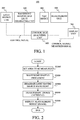
- FIG. 1 schematically illustrates a basic configuration of an imaging apparatus (measurement apparatus) according to the present invention.
- the imaging apparatus 100 includes a light source unit 200, a wavefront shaping and light irradiating unit 300, a measurement unit 500, a control and analyzing unit 600, and a display unit 700.
- the test object 400 to be measured including a living tissue, and its optical property, such as scattering property or absorption property, changes with time at a certain local position in the test object.
- the test object 400 contains an area in which the optical property, such as the scattering property or the absorption property, changes with time.
- the light source unit 200 includes a light source configured to emit light ranging from visible to near infrared wavelength, the wavefront of the light emitted from the light source is shaped by the wavefront shaping and light irradiating unit 300.
- the wavefront-shaped light enters the test object 400.
- the measurement unit 500 measures the light emitted from the test object, such as transmitted light or reflected light.
- the control and analyzing unit 600 controls each component in accordance with processing flow illustrated in FIG. 2 .
- the control and analyzing unit 600 serves as a control apparatus that controls the light source unit 200, the wavefront shaping and light irradiating unit 300, the measurement unit 500, and the display unit 700.
- the control and analyzing unit 600 also analyzes a signal measured by the measurement unit 500.
- FIG. 2 is a view illustrating a basic processing flow of the imaging method according to the present invention. Each step in the flowchart in FIG. 2 is executed by a command of a CPU in the control and analyzing unit 600.
- the CPU sets an area to be measured (measurement area) in the test object 400.
- the wavefront shaping and light irradiating unit 300 and the measurement unit 500 are controlled in such a way that the light can be irradiated onto the area, and the transmitted or reflected light from the test object 400 is measured.
- S2000 the wavefront of the light entering the test object 400 is shaped by wavefront shaping process which will be described later.
- the wavefront-shaped light is irradiated onto the test object.
- the light emitted from the test object is measured (captured) using the measurement unit 500.
- the CPU performs necessary processing for the obtained measurement data or captured image through the control and analyzing unit 600, and then displays the measurement result (image) on the display unit 700 in S5000.
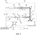
- FIG. 3 is a view of an illustrative apparatus according to this embodiment.
- the imaging apparatus according to this embodiment sets a living tissue, such as a finger or a hand, as the test object 400, captures an image of blood vessel 410 in the test object 400, and provides the image used for medical applications, such as diagnosis.
- the light source unit 200 includes a light source 210, and outputs light 110 collimated with a predetermined beam size by the light source unit 200.
- the light source 210 is a laser that emits continuous wave ("CW") light having a constant intensity with time in a range from visible wavelength to near infrared wavelength, such as 400 nm to 1,500 nm.
- the wavelength may correspond to an absorption spectrum, such as water, fat, protein, oxy-hemoglobin, deoxy-hemoglobin as a main ingredient of the test object 400.
- the wavelength may be outside of the above range if necessary, and the laser may emit light having an intensity modulated at an arbitrary frequency or pulsed light.
- the light intensity irradiated onto the test object 400 is adjusted so as to satisfy the safety standard.
- the light emitted from the light source 210 has a sufficiently long coherence length, such as several tens of centimeters or longer.
- the light emitted from the light source 210 is collimated by a spatial filter 220 and a lens 230, and the beam size and the light intensity are properly adjusted by a variable aperture diaphragm 240 and an ND filter 250.
- the light intensity can be adjusted by directly adjusting the output of the light source 210 instead of the ND filter 250.
- the beam size is adjusted based on the effective region of a spatial light modulator 320, which will be described later.
- the light 110 having the adjusted beam size and light intensity is reflected by the mirror 260, is output from the light source unit 200, and enters the wavefront shaping and light irradiating unit 300.
- the input light 110 transmits a beam splitter ("BS") 310 and enters a spatial light modulator (“SLM") 320.
- the SLM 320 can use, for example, a liquid crystal on silicon (“LCOS").
- the SLM 320 may be a reflection type device, or a transmission type device.
- the SLM 320 is connected to the control and analyzing unit 600 such as PC, and shapes (phase-modulates) the wavefront based on the processing of the wavefront shaping process S2000 in FIG. 2 .
- the SLM 320 serves as a modulator configured to modulate the wavefront of the light entering the test object 400.
- the polarization of the light entering the SLM 320 is adjusted so as to correspond to a polarization direction in which the phase modulation of the SLM 320 works.
- the wavefront-shaped light 120 reflected on the SLM 320 is reflected on the BS 310, passes through the lens (optical system) 330, and is output from the wavefront shaping and light irradiating unit 300.
- the light output from the wavefront shaping and light irradiating unit 300 enters and illuminates the test object 400.
- Each of a distance between the lens 330 and the SLM 320 and a distance between the lens 330 and the incident surface of the test object 400 is equal to a focal length of the lens 330.
- the SLM 320 and the incident surface of the test object 400 have a Fourier transform relationship, and a Fourier-transformed distribution of the wavefront-shaped light by the SLM 320 enters the test object 400.
- the measurement unit 500 serves to measure light emitted from the test object 400.
- the measurement unit 500 includes a lens (optical system) 510 and a CCD 520, and the scattered light 130 forms an image on the CCD 520 via the lens 510.
- a lens optical system
- CCD image intensifier
- EMCCD electrostatic cell detector
- sCMOS image intensifier
- the CCD 520 is connected to and controlled by the PC 600.
- the image captured by the CCD 520 is sent to the PC 600, and received by a data acquiring unit 600a in the PC 600.
- the captured image obtained by the data acquiring unit 600a is analyzed by a processing unit 600b in the PC 600.
- the data acquiring unit 600a and the processing unit 600b are controlled by a control unit 600c in the PC 600.
- the analyzed and generated image is displayed on the monitor 700 as a display unit.
- image processing such as edge emphasis, gamma correction, and color correction, may be performed so that the user can correctly recognize the measurement data and image, if necessary.
- the test object 410 includes a blood vessel 410 to be measured in this apparatus, and a purpose of this embodiment is to enhance the visibility of the blood vessel 410 by sending light to or by focusing light onto the local position.
- this embodiment utilizes a temporal change of the optical property of the blood vessel 410 in the test object 400. Because of the blood flows in the blood vessel 410, a variety of micro objects (scatterers) such as cells flowing in the blood vessel move, which optically result in the change of the scattering property with time. The signal measured by the measurement unit 500 changes due to the influence of this change.
- a change of the signal contained in the measured signal is caused by the change of the optical property in the local blood vessel site.
- One characteristic of this embodiment is to extract this change by statistically processing the measured signal and to use the change as a monitoring signal in the wavefront shaping. Thereby, light can be efficiently focused on the local area (blood vessel volume) in the test object in a noninvasive and noncontact manner so as to form an image of the area without using the fluorescent probe or the ultrasound system.
- a description of a processing flow of this embodiment including the wavefront shaping process utilizing above statistical processing will now be given.
- the basic flow is similar to the one illustrated in FIG. 2 .
- the blood vessel 410 is set and, the wavefront shaping and light irradiating unit 300 and the measurement unit 500 are controlled so that the blood vessel 410 can be measured.
- the measurement area may be set based on a previously captured image of the test object 400 in the premeasurement.
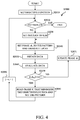
- FIG. 4 a description will be given of the wavefront shaping process in S2000.
- Each step in the flowchart in FIG. 4 is executed in accordance with a command by the controller 600c in the PC 600.
- an objective function is set in S2010 for wavefront shaping (optimizing).
- This objective function is based on a value obtained through the statistical processing (a statistical value) of the image captured by the CCD 520. More specifically, the speckle contrast C S expressed in Expression (1) calculated with the captured image is set as the objective function.
- C s ⁇ s / ⁇ I > where I is a light intensity measured at each pixel in the CCD, ⁇ > is an average value and ⁇ S is a standard deviation of the light intensity I in the image.
- the measurement unit 500 can acquire a temporal change of the optical property in the test object through a plurality of spatial measurements.
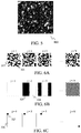
- the objective function is the speckle contrast that relies on the standard deviation of the light intensity I and the average value as expressed in Expression (1). Since the incident light 120 has a relatively long coherence length, the image captured by the CCD 520 is an image 800 containing a random speckle pattern, as schematically illustrated in FIG. 5 .
- the measurement unit 500 is controlled so as to properly adjust the speckle grain size, in order to resolve the speckle grain by the CCD 520, and to measure the speckle contrast C S .
- the speckle grain size may be maintained as small as possible so as to measure as many speckle grains as possible, and evaluate the speckle contrast C S with a statistically large number. Therefore, the pixel size of the CCD 520 may be equal to the speckle grain size or the speckle grain size may slightly be larger than the pixel size of the CCD 520 by several pixels.
- the fluctuation range of the speckle contrast C S in the imaging apparatus 100 may be previously measured and set as a system noise to be used in the following process.
- the wavefront of the light incident on the test object 400 will be modulated (or shaped) by this pattern.
- FIGs. 6A to 6C illustrate some patterns. For example, a randomly distributed pattern of a modulated area 321 (illustrated in black) and a non-modulated area 322 (illustrated in white) may be used, as illustrated in FIG. 6A .
- one (single) segment 327 in the SLM 320 may be set as a pattern as the modulated area.
- the segment means an integrated area of a plurality of pixels in the SLM 320, and is a minimum unit for the phase modulation where the phase is uniformly modulated.
- the segment size may be arbitrarily set according to a measurement condition, and even the pixel size of the SLM can be set as the segment.
- an area 326 other than the segment 327 is the non-modulated area.
- the number of patterns N may arbitrarily be set. As the number of patterns N increases, the SNR of the measured signal improves due to the focusing effect of the wavefront shaping. However, the large the number N, the more iterations required in S2020 and the longer the measurement time becomes. Therefore, the number of patterns N may be set by considering the balance between the measured signal SNR and the measurement time. In addition, each pattern may have a mutually orthogonal basis. After the j-th pattern is selected in S2020, the SLM 320 reads (sets) the pattern in S2030. Here, the pattern may be calculated and generated in S2020 on the fly, or the SLM 320 may read previously stored data out of the memory in the PC 600.
- SLM 320 modulates the phase using the j-th pattern.
- the phase ⁇ i of each pixel i (or segment j) in the j-th pattern is set onto the SLM 320 so as to shape the wavefront of the incident light 120, and to illuminate the test object 400.
- the phase of each pixel i is set as the phase distribution obtained in the (j-1)-th process.
- the measurement unit 500 measures the light 130 emitted from the object 400.
- the data acquiring unit 600a obtains a captured image (measured signal) output from the measurement unit 500.
- the data acquiring unit 600a acquires a measured signal obtained by measuring light emitted from the test object.
- the processing unit 600b calculates the objective function that varies according to the statistical value obtained by statistical processing of the acquired image.
- the processing unit 600b calculates the speckle contrast C S from the acquired image using Expression (1).
- the calculated speckle contrast C S is stored in the memory in the PC 600 with the value of the phase ⁇ k , which will be described later.
- the controller 600c updates (changes) the value of the phase ⁇ i .
- S2071 updates the phase ⁇ i of the pixel i as ⁇ i + ⁇ k ( ⁇ i ⁇ i + ⁇ k ). That is, the controller 600c controls a modulation amount of the wavefront of the light illuminating the test object 400.
- the step size ⁇ is set by considering the measurement accuracy and speed.
- the speckle contrast C S is calculated with the pattern of which phase is newly updated, and stored in the memory in the PC 600. This process is repeated until ⁇ k exceeds 2n, and then the flow moves to S2080. In other words, until the flow moves to S2080, the controller 600c repeats the acquisition (S2050) by the data acquiring unit 600a and the calculation (S2060) by the processing unit 600b.
- the controller 600c controls a modulation amount of a wavefront of the light illuminating the test object so as to minimize the objective function. More specifically, the controller 600c makes the data acquiring unit 600a and the processing unit 600b repeat the above process while changing the modulation amount, and determines the modulation amount where the objective function falls minimum.
- the controller 600c provides such control that the wavefront of the incident light is modulated with the phase distribution where the objective function is minimum.
- the flow moves to a next pattern (j+1) and the process of S2020 to S2080 will be repeated.
- the flow ends when all patterns are processed in S2020 (j N).
- the above explained flow is the wavefront shaping process according to this embodiment, where the incident wavefront is shaped in such a manner that the speckle contrast C S (objective function) of the captured image becomes minimum.
- the wavefront shaping process S2000 may use an algorithm that sequentially optimizes a phase of the pattern displayed in the SLM, as described above.
- a genetic algorithm as disclosed in Donald B. Conkey et al., "Genetic algorithm optimization for focusing through turbid media in noisy environments," Optics Express Vol.20, No.5 4840-4849 (2012 ) may be used.
- the wavefront shaping algorithm is not limited to the aforementioned algorithm but may use an arbitrary optimal algorithm. This embedment is characteristic in terms of setting the objective function as the speckle contrast calculated from the captured image.
- those phases may be set onto the SLM 320 simultaneously instead of setting one-by-one.
- the speckle contrast C S does not change.
- the scattering properties such as a scatting direction and a transport mean free path, changes with time.
- the scattered light traces different paths (with a different optical path length) in the test object, and is emitted from the test object 400.
- the measurement unit 500 measures the emitted light
- a variety of scattered waves with random phases are incoherently superimposed, averaged and imaged in an exposure time period of the CCD 520.
- the speckle contrast C S of the image becomes smaller. Therefore, a change of the speckle contrast C S depends on a change of the changing site (blood vessel 410) as well as an amount of light passing through the changing site after the light enters the test object 400.
- the speckle contrast C S decreases as the light passing through the blood vessel 410 increases. Utilizing this effect, this embodiment sets the speckle contrast C S as an objective function. And the wavefront of the incident light is shaped so that the objective function becomes as small as possible.
- the incident wavefront obtained by this optimization generates a wavefront that is most influenced by the blood vessel 410. Therefore, irradiating this wavefront-shaped light results in the intensive irradiation onto the blood vessel 410 in the test object 400.
- the objective function is not limited to the speckle contrast C S and may use another statistical value, such as a variance ⁇ S 2 or a standard deviation ⁇ S of the image.
- the statistical value according to this embodiment may be at least one of the standard deviation, the variance, and the average of the intensity of the captured image (measured signal).
- the wavefront-shaped light is irradiated onto the test object 400 and the blood vessel 410 in the test object is measured in the S3000 to S4000 in the measurement flow illustrated in FIG. 2 .
- the blood vessel 410 in the test object can be imaged with high contrast and high SNR, while it has conventionally been measured with low contrast and low SNR.
- the captured image may be displayed on the monitor 700.
- the captured image may be displayed in addition to another image, such as another diagnosis result or measurement data, which may be superimposed, if necessary.
- the SLM 320 is not limited to the phase modulation SLM, but an amplitude modulation SLM may also be applicable.
- the SLM may be a LCOS that modulates an amplitude or a digital mirror device ("DMD").
- the DMD may generate a distribution of binary amplitude modulation by turning off the pixels in the DMD where the speckle contrast C S (the objective function) increases and by turning on the pixels where the objective function decreases.
- the test object may be measured with incident light shaped by this binary amplitude modulation.
- the phase may be modulated with a DMD of the binary amplitude modulation, as disclosed in Antonio M. Caravaca-Aguirre, Eyal Niv, Donald B.
- the modulator configured to modulate the wavefront of the light irradiated onto the test object 400 may use at least one of the phase modulation or the amplitude modulation. Accordingly the controller 600c controls at least one of the phase modulation amount or the amplitude modulation amount.
- the wavelength property (spectrum property) of the blood vessel 410 of the test object 400 may be visualized by repeating the measurement with a different wavelength of the light source 210.
- the above process with a plurality of arbitrary wavelengths can provide information regarding component ratio of oxy-hemoglobin, deoxy-hemoglobin, water, or metabolic information of oxygen saturation based on the spectral property of a measured blood vessel site.
- the configuration of the imaging apparatus according to this embodiment is the same as that of the first embodiment illustrated in FIG. 3 , except the CCD 520 in the measurement unit 500, which is a CCD that can take images at high frame rate, such as several hundreds of frames per second ("fps") or higher.
- the measurement flow is similar to that of illustrated in FIG. 2 , and the flow of the wavefront shaping process S2000 is basically similar to that in FIG. 4 .
- This embodiment is different from the first embodiment as to setting the objective function in S2010, acquiring data in S2050, and evaluating the data in S2060.
- the controller 600c sets a target area in the captured image (measured signal).
- the target area is an area in the test object 400 where the optical property changes with time.
- the N images are evaluated with respect to the previously set the target area in the captured image (for example, in S1000 or S2010).
- the processing unit 600b calculates an objective function within the set target area in the captured image. This target area is set so as to contain the blood vessel 410.
- the data is evaluated by statistical process on each pixel in the target area of the N image frames. For example, the speckle contrast C t is calculated among the frames as follows by addressing a certain pixel (x, y) in the target area.
- the measurement unit 500 can thus acquire a change of the optical property with time in the test object by performing a plurality of measurements within the measurement time.
- the thus calculated speckle contrast C t is a value that reflects the influence of the blood flow in the blood vessel 410 in the test object 400, similar to the first embodiment. For example, when the speckle contrast C t is compared between the pixels within the blood vessel 410 and the pixels of other steady area in the captured image, the former speckle contrast C t is smaller than the latter one.
- one data evaluating method in S2060 is to extract the blood vessel site in the target area from the image, and to monitor the speckle contrast C t of one arbitrary pixel in the target area as the objective function.
- a sum ( ⁇ C t (x, y)) or an average ( ⁇ C t (x, y)>) of the speckle contrasts C t of a plurality of pixels in the blood vessel area may be monitored.
- the speckle contrasts C t may be evaluated at a plurality of different positions in the blood vessel area, and a linear sum of them with arbitrary coefficients may be monitored.
- the speckle contrast C t is set as the objective function for the wavefront shaping process, and executes the wavefront shaping process so as to decrease the objective function.
- the captured image contains the blood vessel 410 but the wavefront shaping process S2000 does not expressly specify the blood vessel site 410.
- this embodiment specifies the blood vessel site 410 in the image and evaluates the speckle contrast at the site.
- the test object 400 contains a plurality of blood vessels, it is more effective to specify the blood vessels in order to shape the wavefront and take images as explained in this embodiment.
- the wavefront shaping process S2000 sets, in S2010, a pixel (x, y) or an area in the captured image as the target area to be evaluated in S2060.
- the blood vessel 410 may be extracted by the image processing and the specified pixels may be evaluated as the target area.
- pixels containing the blood vessel 410 and its surrounding pixels may be set as the target area.
- the objective function may be based on the speckle contrast C t as expressed in Expression (2).
- the incident wavefront is shaped by iterating the data acquisition in S2050 and the data evaluation in S2060, as described above, with respect to the objective function.
- the process after the wavefront shaping may be executed based on FIG. 2 as described in the first embodiment.
- the light irradiation in S3000 in FIG. 2 uses the wavefront obtained in S2000, as described above, and the image is obtained in S4000 by scanning the incident angle over the target area in the test object 400.
- the SLM 320 may be placed on a multi-axis stage and the stage may be sequentially tilted according to the scanning amount of the SLM 320.
- a linear phase shift corresponding to the scanning may be added to the phase distribution obtained in S2000 and set onto the SLM 320.
- the controller 600c may control the SLM 320 so as to scan the test object 400 with the wavefront-shaped light. This scan is performed within a so called memory effect range where correlation of scattering is preserved.
- the focusing effect on the blood vessel 410 obtained in S2000 is maintained because scattering is correlated.
- This effect can also provide an image near the blood vessel 410 (within the range of the memory effect).
- the range of the memory effect may be obtained in advance by calculating a correlation between the images obtained with different incident angles.
- the light irradiation in S3000 may increase the light intensity output from the light source unit 200 if necessary, and take images of the test object 400.
- the data acquisition in S2050 may set an image size to be as small as possible, in order to increase the frame rate of the CCD 520, as long as the blood vessel 410 is within the image.
- this embodiment may use a method for calculating a difference between each frame of the N images, and calculating a standard deviation where the background is removed or suppressed.
- the method disclosed in Liu may be used so as to precisely extract the blood vessel 410 from the test object 400.
- a standard deviation calculated after such processing is performed may be used as the objective function.
- FIG. 3 A description will now be given of an imaging method and an imaging apparatus according to a third embodiment of the present invention.
- the apparatus according to this embodiment also has a basic configuration illustrated in FIG. 3 .
- a characteristic configuration of the wavefront shaping and light irradiating unit 300 and the measurement unit 500 in this embodiment will be described with reference to FIG. 8 that is an illustrative drawing.
- a wavefront of the light 110 output from the light source unit 200 is shaped by the SLM 320, and the light is coupled with an optical fiber 350 via the optical system 330.
- the test object 400 (containing the blood vessel 410) is irradiated by the light emitted from the exit end of the optical fiber 350.
- the optical fiber 350 may be a fiber bundle of single-mode fibers or one multi-mode fiber.
- the measurement unit 500 includes an optical system 510 for focusing the light output from the unit 300 on a photodetector 540, the photodetector 540, and a correlator 550 configured to measure a temporal correlation of the signal from the photodetector 540 in real time.
- the photodetector 540 may be a single detector, such as a photodiode (PD), or an avalanche photo-diode (APD), or a photomultiplier (PMT).
- the signal from the photodetector 540 may be amplified by an amplifier.
- the photodetector 540 can be an area sensor, however, a single detector may be desirable because of faster response and higher sensitivity.
- the correlator 550 also performs A/D-conversion of the signal from the photodetector 540, and calculates and outputs the correlation of the obtained digital signal.
- the imaging apparatus according to the present invention is applicable to an endoscope that inserts the optical fiber 350 into the test object 400 to observe inside of the test object.
- the basic imaging flow in this apparatus is similar to that of illustrated in FIG. 2 .
- a description will now be given of the characteristic wavefront shaping process according to this embodiment.
- the photodetector 540 detects light that has entered the test object 400 and passed through the blood vessel 410.
- the correlation G 1 ( ⁇ ) of the electric field is measured.
- G 1 ⁇ ⁇ E 0 E * ⁇ >
- the correlation output from the correlator 550 is not a correlation of the electric field E, but a correlation G 2 ( ⁇ ) of the light intensity I as follows.
- G 2 ⁇ ⁇ I 0 I * ⁇ >
- G 1 ( ⁇ ) ⁇ I > 2 + ⁇ G 1 ⁇ 2
- ⁇ a parameter depending on the measurement condition.
- a signal of the correlation G 1 ( ⁇ ) attenuates with time in accordance with a change of scattering caused by the blood flow, as schematically illustrated in FIG. 9 .
- This temporal correlation is the statistical value obtained through statistically processing a plurality of measured signals.
- the temporal change of the correlation G 1 ( ⁇ ) attenuates significantly as the blood flow increases (as the change increases).
- the correlation G 1 ( ⁇ ) also significantly attenuates. Therefore, a value of the correlation G 1 ( ⁇ ) can be used as a monitoring signal.
- G 1 ( ⁇ ) when the wavefront is shaped so that G 1 ( ⁇ ) can significantly attenuate, an amount of the detected light that passes through the blood vessel site relatively increases.
- the objective function is set based on a correlation value output from the correlator 550 in S2010.
- the magnitude of the attenuation of the correlation value output from the correlator 550 is set as the objective function.
- the correlation value is acquired through the detection by the detector 540 during the measurement time period ⁇ and output from the correlator 550.
- the attenuation is evaluated with respect to the measured correlation value.
- the subsequent process flow is similar to that of in the first embodiment.
- the phase is selected so that the objective function G 1 ( ⁇ ) or a reciprocal of
- the wavefront shaping process S2000 enables the generation of an incident light to be efficiently focused on the blood vessel 410 in the test object 400.
- the optical property, such as an absorption property and a scattering property, in the blood vessel site may be measured with the above wavefront in S3000 and S4000 illustrated in FIG. 2 , and a spectral property may be measured by changing the wavelength of the incident light.
- a spectral property may be measured by changing the wavelength of the incident light.
- the measurement unit 500 may include an image capturing unit configured to capture the test object 400.
- the light emitted from the test object 400 enters the measurement unit 500, and part of it passes a BS 560 via an optical system 510 and is imaged on a CCD 520.
- Another part of the light is reflected on the BS 560, and detected by a PD 540 via an optical system 570.
- the signal output from the PD 540 is digitized, and the correlation function G 1 ( ⁇ ) is measured by a correlator 550.
- the signal detected by the PD 540 corresponds to part of the signal captured by the CCD 520.
- the target area that contains the blood vessel 410 to be measured is set based on the image captured by the CCD 520 as the objective function setting in S2010.
- the optical system 570 and the PD 540 are adjusted so that the PD 540 can detect the signal from the area corresponding to the blood vessel 410.
- the area used to measure the correlation G 1 ( ⁇ ) may be adjusted by confirming the previously measured image.
- this apparatus can specify the target area first and then measure the correlation G 1 ( ⁇ ).
- the objective function is set as a reciprocal of the magnitude of the attenuation of the correlation G 1 ( ⁇ ) in a certain measurement time period ⁇ .
- the image is captured by the CCD 520, and the speckle contrast C S (or C t ) may be evaluated and added to the objective function.
- the objective function may be evaluated so that both the speckle contrast and the reciprocal of the attenuation of the correlation G 1 ( ⁇ ) can be small.
- the value of the speckle contrast C S in an area may be set as a constraint condition, and keep the speckle contrast C S within a range of the constraint condition, and the objective function may be evaluated so that G 1 ( ⁇ ) can more significantly attenuate.
- the objective function is evaluated based on the outputs from the CCD 520 and the correlator 550. Finally, in S2080, a phase distribution that minimizes the objective function is selected for each pattern, and the wavefront is shaped.
- the imaging apparatus according to this embodiment has the same configuration according to the first embodiment illustrated in FIG. 3 or may have the configuration according to the third embodiment illustrated in FIG. 10 .
- This embodiment evaluates a contrast of a signal from the blood vessel site in the captured image in addition to the speckle contrast or the correlation as the objective function evaluated in wavefront shaping process S2000.
- a target area 830 is set in the image 820 captured in the CCD 520 ( FIG. 11A ).
- a contrast value V of a signal is evaluated based on an arbitrary one-dimensional sectional distribution ( FIG. 11B ) which contains the blood vessel site.
- V I max ⁇ I min / I max + I min where I max and I min are a maximum value and a minimum value near the blood vessel site.
- the contrast of the absorptive object decreases.
- the signal contrast V improves.
- the wavefront shaping process can be executed in addition to the speckle contrast.
- the image is acquired in S2050, and the speckle contrast C S and the signal contrast V of the absorption image are measured based on the captured image, and the objective function is evaluated based on Expression (7) in S2060. More specifically, the processing unit 600b calculates the contrast value of the image obtained by the image capturing unit, such as the CCD 520 illustrated in FIGs. 3 and 10 . In addition, the processing unit 600b calculates the objective function in accordance with Expression (7) using the contrast value and the speckle contrast C S (or the statistical value, such as the standard deviation and the average value of the light intensity I) as variables. In S2070 to S2071, this procedure is repeated by updating the phase, and the phase that minimizes the objective function ⁇ is read out and set as the phase of the pattern in S2080.
- the incident wavefront is shaped by iterating this procedure with different patterns. After the incident wavefront is obtained, the test object 400 is measured in accordance with the measurement flow illustrated in FIG. 2 . Thereby, this embodiment shapes the wavefront so as to focus the light on the changing site caused by the blood flow, and directly controls the quality of the observed image through the wavefront shaping.
- This embodiment combines the signal contrast V with the speckle contrast C S expressed in Expression (1), but may combine the signal contrast V with the speckle contrast C t expressed in Expression (2) or the correlation function G 1 ( ⁇ ) expressed in Expression (3).
- the present invention utilizes an optical change in the test object.
- the present invention extracts this change by statistically processing the measurement data, shapes the wavefront of the light incident on the test object so that the change becomes remarkable by monitoring the obtained objective function, and then irradiates the light onto the test object.
- This embodiment is applicable to imaging, a variety of optical measurements, and diagnosis, by efficiently irradiating light onto a changing spot in the test object.
- the signal source is not limited to the blood vessel, as long as the dynamic optical property component can be measured in the test object.
- the test object is not limited to the biological tissues, such as a human body, and the present invention is applicable to any media that satisfy the above condition.
- the objective function may be generated by arbitrarily combining the evaluated values obtained by the described statistical processing.
- the present invention can focus light inside the test object in a noninvasive and noncontact manner with a relatively simple apparatus configuration.
- the present invention is robust to unexpected noises by the difference, and can provide precise measurement or imaging of the optical property in the test object.
- Embodiment(s) of the present invention can also be realized by a computer of a system or apparatus that reads out and executes computer executable instructions (e.g., one or more programs) recorded on a storage medium (which may also be referred to more fully as a 'non-transitory computer-readable storage medium') to perform the functions of one or more of the above-described embodiment(s) and/or that includes one or more circuits (e.g., application specific integrated circuit (ASIC)) for performing the functions of one or more of the above-described embodiment(s), and by a method performed by the computer of the system or apparatus by, for example, reading out and executing the computer executable instructions from the storage medium to perform the functions of one or more of the above-described embodiment(s) and/or controlling the one or more circuits to perform the functions of one or more of the above-described embodiment(s).
- computer executable instructions e.g., one or more programs
- a storage medium which may also be referred to more fully as
- the computer may comprise one or more processors (e.g., central processing unit (CPU), micro processing unit (MPU)) and may include a network of separate computers or separate processors to read out and execute the computer executable instructions.
- the computer executable instructions may be provided to the computer, for example, from a network or the storage medium.
- the storage medium may include, for example, one or more of a hard disk, a random-access memory (RAM), a read only memory (ROM), a storage of distributed computing systems, an optical disk (such as a compact disc (CD), digital versatile disc (DVD), or Blu-ray Disc (BD)TM), a flash memory device, a memory card, and the like.
- a control apparatus (600) includes a data acquiring unit (600a) configured to acquire a measured signal obtained by measuring light emitted from a test object onto which light is irradiated, a processing unit (600b) configured to calculate an objective function that varies in accordance with a statistical value obtained by statistically processing the measured signal, and a controller (600c) configured to control a modulation amount of a wavefront of the light irradiated onto the test object so as to minimize the objective function.
- a data acquiring unit (600a) configured to acquire a measured signal obtained by measuring light emitted from a test object onto which light is irradiated
- a processing unit (600b) configured to calculate an objective function that varies in accordance with a statistical value obtained by statistically processing the measured signal
- a controller (600c) configured to control a modulation amount of a wavefront of the light irradiated onto the test object so as to minimize the objective function.
Landscapes
- Health & Medical Sciences (AREA)
- Life Sciences & Earth Sciences (AREA)
- Physics & Mathematics (AREA)
- General Health & Medical Sciences (AREA)
- Pathology (AREA)
- Molecular Biology (AREA)
- Animal Behavior & Ethology (AREA)
- Veterinary Medicine (AREA)
- Engineering & Computer Science (AREA)
- Biomedical Technology (AREA)
- Heart & Thoracic Surgery (AREA)
- Medical Informatics (AREA)
- Public Health (AREA)
- Surgery (AREA)
- Biophysics (AREA)
- Optics & Photonics (AREA)
- Chemical & Material Sciences (AREA)
- Analytical Chemistry (AREA)
- Biochemistry (AREA)
- General Physics & Mathematics (AREA)
- Immunology (AREA)
- Vascular Medicine (AREA)
- Cardiology (AREA)
- Physiology (AREA)
- Investigating Or Analysing Materials By Optical Means (AREA)
Applications Claiming Priority (1)
| Application Number | Priority Date | Filing Date | Title |
|---|---|---|---|
| JP2015102449A JP2016217860A (ja) | 2015-05-20 | 2015-05-20 | 制御装置、測定装置、制御方法、プログラム、記憶媒体 |
Publications (1)
| Publication Number | Publication Date |
|---|---|
| EP3096129A1 true EP3096129A1 (en) | 2016-11-23 |
Family
ID=56368757
Family Applications (1)
| Application Number | Title | Priority Date | Filing Date |
|---|---|---|---|
| EP16169532.5A Withdrawn EP3096129A1 (en) | 2015-05-20 | 2016-05-13 | Control apparatus, measurement apparatus, control method, program, and storage medium |
Country Status (3)
| Country | Link |
|---|---|
| US (1) | US10194803B2 (enExample) |
| EP (1) | EP3096129A1 (enExample) |
| JP (1) | JP2016217860A (enExample) |
Cited By (1)
| Publication number | Priority date | Publication date | Assignee | Title |
|---|---|---|---|---|
| WO2019058122A1 (en) * | 2017-09-22 | 2019-03-28 | University Court Of The University Of St Andrews | IMAGING A SAMPLE THROUGH A BROADCAST ENVIRONMENT |
Families Citing this family (15)
| Publication number | Priority date | Publication date | Assignee | Title |
|---|---|---|---|---|
| JP2016150081A (ja) * | 2015-02-17 | 2016-08-22 | ソニー株式会社 | 光学ユニット、測定システムおよび測定方法 |
| JP6589672B2 (ja) * | 2016-02-08 | 2019-10-16 | コニカミノルタ株式会社 | 移動量検出器、およびそれを備えた画像形成装置 |
| US10162086B2 (en) * | 2016-03-07 | 2018-12-25 | Microsoft Technology Licensing, Llc | Imaging through highly diffusive media with wavefront shaping |
| US20170325693A1 (en) * | 2016-05-10 | 2017-11-16 | Canon Kabushiki Kaisha | Photoacoustic apparatus and control method of photoacoustic apparatus |
| US10578553B2 (en) * | 2016-11-29 | 2020-03-03 | Pioneer Corporation | Measuring apparatus |
| JP6862255B2 (ja) * | 2017-04-12 | 2021-04-21 | キヤノン株式会社 | 撮像装置、撮像方法および撮像プログラム |
| WO2019027697A1 (en) | 2017-07-31 | 2019-02-07 | Wayne State University | OMNIDIRECTIONAL PHOTOACOUSTIC TOMOGRAPHY SYSTEM |
| CN109452944B (zh) * | 2017-09-06 | 2023-08-15 | 东北大学 | 基于荧光脉搏波的血液荧光物质无创检测系统 |
| SE542345C2 (en) * | 2018-08-03 | 2020-04-14 | Redsense Medical Ab | Device for measuring a property of a measurement object by luminescence |
| US20230347036A1 (en) * | 2020-07-08 | 2023-11-02 | I--Sep | Device For Determining The Level Of Haemoglobin Or Haematocrit Of A Circulating Liquid |
| JP7693294B2 (ja) * | 2020-10-14 | 2025-06-17 | キヤノン株式会社 | 測定装置、測定方法、およびプログラム |
| CN113176209B (zh) * | 2021-04-12 | 2022-09-16 | 中山大学 | 一种超声调制光学成像方法 |
| CN116266409A (zh) * | 2021-12-16 | 2023-06-20 | 北京与光科技有限公司 | 识别系统及其工作方法 |
| JPWO2024176997A1 (enExample) * | 2023-02-20 | 2024-08-29 | ||
| US12353802B1 (en) * | 2024-06-27 | 2025-07-08 | Jinling Institute Of Technology | Model-based adaptive multi-aperture optical fiber coupling control system and method |
Citations (8)
| Publication number | Priority date | Publication date | Assignee | Title |
|---|---|---|---|---|
| US6076010A (en) * | 1996-06-20 | 2000-06-13 | Trustees Of The University Of Pennsylvania | Imaging spatially varying dynamic media with diffusing correlation waves |
| US20090118622A1 (en) * | 2007-11-06 | 2009-05-07 | The Regents Of The University Of California | APPARATUS AND METHOD FOR WIDEFIELD FUNCTIONAL IMAGING (WiFI) USING INTEGRATED STRUCTURED ILLUMINATION AND LASER SPECKLE IMAGING |
| US20110083509A1 (en) | 2009-10-09 | 2011-04-14 | Nellcor Puritan Bennett Llc | Photoacoustic Spectroscopy With Focused Light |
| US20120127557A1 (en) | 2010-11-19 | 2012-05-24 | Canon Kabushiki Kaisha | Apparatus and method for irradiating a medium |
| WO2012080838A2 (en) * | 2010-12-17 | 2012-06-21 | Canon Kabushiki Kaisha | Apparatus and method for irradiating a scattering medium |
| US20130182253A1 (en) | 2011-01-19 | 2013-07-18 | Howard Hughes Medical Institute | Wavefront compensation for deep tissue optical microscopy |
| US20140206980A1 (en) * | 2013-01-23 | 2014-07-24 | Nanyang Technological University | Deep tissue flowmetry using diffuse speckle contrast analysis |
| WO2015031395A1 (en) * | 2013-08-26 | 2015-03-05 | The Regents Of The University Of Colorado | Imaging through scattering media with high signal to noise ratio and resolution |
Family Cites Families (22)
| Publication number | Priority date | Publication date | Assignee | Title |
|---|---|---|---|---|
| JPH09159606A (ja) | 1995-07-31 | 1997-06-20 | Instrumentation Metrics Inc | 液体相関分光測定法 |
| SG38866A1 (en) | 1995-07-31 | 1997-04-17 | Instrumentation Metrics Inc | Liquid correlation spectrometry |
| US7295592B2 (en) * | 2002-03-08 | 2007-11-13 | Sharp Kabushiki Kaisha | Light source device and optical communication module employing the device |
| US7761139B2 (en) * | 2003-01-24 | 2010-07-20 | The General Hospital Corporation | System and method for identifying tissue using low-coherence interferometry |
| CA2519937C (en) * | 2003-03-31 | 2012-11-20 | Guillermo J. Tearney | Speckle reduction in optical coherence tomography by path length encoded angular compounding |
| AU2005270037B2 (en) * | 2004-07-02 | 2012-02-09 | The General Hospital Corporation | Endoscopic imaging probe comprising dual clad fibre |
| US20080002211A1 (en) * | 2006-01-20 | 2008-01-03 | The General Hospital Corporation | System, arrangement and process for providing speckle reductions using a wave front modulation for optical coherence tomography |
| US8125648B2 (en) * | 2006-06-05 | 2012-02-28 | Board Of Regents, The University Of Texas System | Polarization-sensitive spectral interferometry |
| US7995814B2 (en) * | 2006-06-26 | 2011-08-09 | California Institute Of Technology | Dynamic motion contrast and transverse flow estimation using optical coherence tomography |
| JP4935736B2 (ja) * | 2008-03-26 | 2012-05-23 | ソニー株式会社 | 光記録方法及び光記録装置 |
| JP5183381B2 (ja) * | 2008-09-16 | 2013-04-17 | キヤノン株式会社 | 測定装置及び測定方法 |
| WO2010096447A2 (en) * | 2009-02-17 | 2010-08-26 | Board Of Regents, The University Of Texas System | Quantitative imaging with multi-exposure speckle imaging (mesi) |
| US9351642B2 (en) * | 2009-03-12 | 2016-05-31 | The General Hospital Corporation | Non-contact optical system, computer-accessible medium and method for measurement at least one mechanical property of tissue using coherent speckle technique(s) |
| JP5783779B2 (ja) | 2011-04-18 | 2015-09-24 | キヤノン株式会社 | 被検体情報取得装置及び被検体情報取得方法 |
| US20130109963A1 (en) * | 2011-10-31 | 2013-05-02 | The University Of Connecticut | Method and apparatus for medical imaging using combined near-infrared optical tomography, fluorescent tomography and ultrasound |
| US9743839B2 (en) * | 2011-11-02 | 2017-08-29 | Seno Medical Instruments, Inc. | Playback mode in an optoacoustic imaging system |
| CA2883402A1 (en) * | 2012-09-10 | 2014-03-13 | Oregon Health & Science University | Quantification of local circulation with oct angiography |
| US20140378845A1 (en) * | 2013-06-19 | 2014-12-25 | The General Hospital Corporation | Apparatus, devices and methods for obtaining omnidirectional viewing by a catheter |
| JP6196825B2 (ja) | 2013-07-09 | 2017-09-13 | オリンパス株式会社 | 顕微鏡システム、及び、試料の屈折率測定方法 |
| US20160232427A1 (en) * | 2014-11-04 | 2016-08-11 | Vanderbilt University | Spectral fractionation detection of gold nanorod contrast agents using optical coherence tomography |
| US10070796B2 (en) * | 2015-02-04 | 2018-09-11 | General Electric Company | Systems and methods for quantitative microcirculation state monitoring |
| US9861319B2 (en) * | 2015-03-23 | 2018-01-09 | University Of Kentucky Research Foundation | Noncontact three-dimensional diffuse optical imaging of deep tissue blood flow distribution |
-
2015
- 2015-05-20 JP JP2015102449A patent/JP2016217860A/ja not_active Withdrawn
-
2016
- 2016-05-12 US US15/152,759 patent/US10194803B2/en not_active Expired - Fee Related
- 2016-05-13 EP EP16169532.5A patent/EP3096129A1/en not_active Withdrawn
Patent Citations (8)
| Publication number | Priority date | Publication date | Assignee | Title |
|---|---|---|---|---|
| US6076010A (en) * | 1996-06-20 | 2000-06-13 | Trustees Of The University Of Pennsylvania | Imaging spatially varying dynamic media with diffusing correlation waves |
| US20090118622A1 (en) * | 2007-11-06 | 2009-05-07 | The Regents Of The University Of California | APPARATUS AND METHOD FOR WIDEFIELD FUNCTIONAL IMAGING (WiFI) USING INTEGRATED STRUCTURED ILLUMINATION AND LASER SPECKLE IMAGING |
| US20110083509A1 (en) | 2009-10-09 | 2011-04-14 | Nellcor Puritan Bennett Llc | Photoacoustic Spectroscopy With Focused Light |
| US20120127557A1 (en) | 2010-11-19 | 2012-05-24 | Canon Kabushiki Kaisha | Apparatus and method for irradiating a medium |
| WO2012080838A2 (en) * | 2010-12-17 | 2012-06-21 | Canon Kabushiki Kaisha | Apparatus and method for irradiating a scattering medium |
| US20130182253A1 (en) | 2011-01-19 | 2013-07-18 | Howard Hughes Medical Institute | Wavefront compensation for deep tissue optical microscopy |
| US20140206980A1 (en) * | 2013-01-23 | 2014-07-24 | Nanyang Technological University | Deep tissue flowmetry using diffuse speckle contrast analysis |
| WO2015031395A1 (en) * | 2013-08-26 | 2015-03-05 | The Regents Of The University Of Colorado | Imaging through scattering media with high signal to noise ratio and resolution |
Non-Patent Citations (9)
| Title |
|---|
| ANTONIO M. CARAVACA-AGUIRRE; EYAL NIV; DONALD B. CONKEY; RAFAEL PIESTUN ET AL.: "Real-time resilient focusing through a bending multimode fiber", OPTICS EXPRESS, vol. 21, no. 10, 2012, pages 12881 - 12887 |
| C. MA ET AL.: "Time-reversed adapted-perturbation (TRAP) optical focusing onto dynamic objects inside scattering media", NATURE PHOTONICS, 2014 |
| CHENG MA ET AL: "Time-reversed adapted-perturbation (TRAP) optical focusing onto dynamic objects inside scattering media", NATURE PHOTONICS, vol. 8, no. 12, 2 November 2014 (2014-11-02), UK, pages 931 - 936, XP055305717, ISSN: 1749-4885, DOI: 10.1038/nphoton.2014.251 * |
| DONALD B CONKEY ET AL: "Genetic algorithm optimization for focusing through turbid media in noisy environments", OPT. LETT. OPT. COMMUN. OPT. LETT. PHYS. REV. LETT. OPT. EXPRESS OPT. EXPRESS J. NATL. CANCER INST. OPT. LETT. NAT. PHOTONICS 12. B. ANNU. REV. NEUROSCI. NAT. METHODS PRACTICAL GENETIC ALGORITHMS OPT. LETT. NAT. PHOTONICS, 1 January 2012 (2012-01-01), pages 2309 - 2311, XP055305718, Retrieved from the Internet <URL:https://www.osapublishing.org/DirectPDFAccess/2B6D4218-ED2B-6E3C-88FDF570E4B4DC17_227654/oe-20-5-4840.pdf?da=1&id=227654&seq=0&mobile=no> [retrieved on 20160929] * |
| DONALD B. CONKEY ET AL.: "Genetic algorithm optimization for focusing through turbid media in noisy environments", OPTICS EXPRESS, vol. 20, no. 5, 2012, pages 4840 - 4849 |
| I. M. VELLEKOOP ET AL: "Demixing light paths inside disordered metamaterials", OPTICS EXPRESS, vol. 16, no. 1, 1 January 2008 (2008-01-01), pages 67 - 80, XP055306229, DOI: 10.1364/OE.16.000067 * |
| I. M. VELLEKOOP; A. P. MOSK: "Focusing coherent light through opaque strongly scattering media", OPTICS LETTERS, vol. 32, no. 16, 2007, pages 2309 - 2311, XP001506776, DOI: doi:10.1364/OL.32.002309 |
| LIU RONG ET AL: "Motion-contrast laser speckle imaging of microcirculation within tissue beds", JOURNAL OF BIOMEDICAL OPTICS, S P I E - INTERNATIONAL SOCIETY FOR OPTICAL ENGINEERING, US, vol. 18, no. 6, 1 June 2013 (2013-06-01), pages 60508, XP060024182, ISSN: 1083-3668, [retrieved on 20130626], DOI: 10.1117/1.JBO.18.6.060508 * |
| RONG LIU; JIA QIN; RUIKANG K. WANG: "Motion-contrast laser speckle imaging of microcirculation within tissue beds in vivo", JOURNAL OF BIOMEDICAL OPTICS, vol. 8, no. 6, 2013, pages 060508 |
Cited By (3)
| Publication number | Priority date | Publication date | Assignee | Title |
|---|---|---|---|---|
| WO2019058122A1 (en) * | 2017-09-22 | 2019-03-28 | University Court Of The University Of St Andrews | IMAGING A SAMPLE THROUGH A BROADCAST ENVIRONMENT |
| GB2566115B (en) * | 2017-09-22 | 2020-04-01 | Univ Court Univ St Andrews | Imaging of a sample through a scattering medium |
| US11204319B2 (en) | 2017-09-22 | 2021-12-21 | University Court Of The University Of St Andrews | Imaging of a sample through a scattering medium |
Also Published As
| Publication number | Publication date |
|---|---|
| US20160338592A1 (en) | 2016-11-24 |
| JP2016217860A (ja) | 2016-12-22 |
| US10194803B2 (en) | 2019-02-05 |
Similar Documents
| Publication | Publication Date | Title |
|---|---|---|
| US10194803B2 (en) | Control apparatus, measurement apparatus, control method, and storage medium | |
| US9737216B2 (en) | Object information acquiring apparatus and method for controlling object information acquiring apparatus | |
| JP5201920B2 (ja) | 測定装置 | |
| JP5183381B2 (ja) | 測定装置及び測定方法 | |
| US20160150968A1 (en) | Object information acquiring apparatus | |
| JP6108705B2 (ja) | 被検体情報取得装置、および、被検体情報取得方法 | |
| US10362933B2 (en) | Ophthalmologic apparatus, tomographic image generation method, and program that determine an imaging region for capturing a plurality of tomographic images for generating an averaged tomographic image | |
| JP5613337B2 (ja) | 媒体を照射する装置 | |
| CN108882881B (zh) | 图像分析设备和图像分析方法 | |
| EP1639350A1 (en) | Analysis apparatus and method comprising auto-focusing means | |
| JP2010164351A (ja) | 光断層画像化装置 | |
| US20160058295A1 (en) | Photoacoustic wave measurement apparatus and photoacoustic wave measurement method | |
| US20210169333A1 (en) | System and method for calculating a characteristic of a region of interest of an individual | |
| KR20140067522A (ko) | 단층 영상 생성 장치 및 단층 영상 생성 방법 | |
| JP2018100923A (ja) | 光照射装置、光照射方法および光照射プログラム | |
| JP6296759B2 (ja) | 被検体情報取得装置 | |
| JP6486085B2 (ja) | 光音響波測定装置 | |
| US20190142277A1 (en) | Photoacoustic apparatus and object information acquiring method | |
| US20170215804A1 (en) | Object information acquiring apparatus and signal processing method | |
| US9597020B2 (en) | Measuring device and glucose concentration measurement method of the measuring device | |
| JP2018179529A (ja) | 応答特性取得装置、応答特性取得方法および応答特性取得プログラム | |
| US20250049338A1 (en) | Interferometer-based synthetic multi-exposure speckle imaging (symesi) method and system | |
| KR102398853B1 (ko) | 광간섭 신호 기반 산란 매체의 체적 운동 측정 방법, oct 신호의 보상 방법, 및 이를 수행하는 oct 장치 | |
| JP7693294B2 (ja) | 測定装置、測定方法、およびプログラム | |
| WO2025100325A1 (ja) | 光計測装置および解析方法 |
Legal Events
| Date | Code | Title | Description |
|---|---|---|---|
| PUAI | Public reference made under article 153(3) epc to a published international application that has entered the european phase |
Free format text: ORIGINAL CODE: 0009012 |
|
| AK | Designated contracting states |
Kind code of ref document: A1 Designated state(s): AL AT BE BG CH CY CZ DE DK EE ES FI FR GB GR HR HU IE IS IT LI LT LU LV MC MK MT NL NO PL PT RO RS SE SI SK SM TR |
|
| AX | Request for extension of the european patent |
Extension state: BA ME |
|
| 17P | Request for examination filed |
Effective date: 20170523 |
|
| RBV | Designated contracting states (corrected) |
Designated state(s): AL AT BE BG CH CY CZ DE DK EE ES FI FR GB GR HR HU IE IS IT LI LT LU LV MC MK MT NL NO PL PT RO RS SE SI SK SM TR |
|
| STAA | Information on the status of an ep patent application or granted ep patent |
Free format text: STATUS: THE APPLICATION HAS BEEN WITHDRAWN |
|
| 18W | Application withdrawn |
Effective date: 20190228 |