EP3096039A1 - Kupplung, kupplungsanordnung und arbeitsmaschine - Google Patents
Kupplung, kupplungsanordnung und arbeitsmaschine Download PDFInfo
- Publication number
- EP3096039A1 EP3096039A1 EP16170590.0A EP16170590A EP3096039A1 EP 3096039 A1 EP3096039 A1 EP 3096039A1 EP 16170590 A EP16170590 A EP 16170590A EP 3096039 A1 EP3096039 A1 EP 3096039A1
- Authority
- EP
- European Patent Office
- Prior art keywords
- coupling
- clutch
- monitoring means
- torque
- monitoring
- Prior art date
- Legal status (The legal status is an assumption and is not a legal conclusion. Google has not performed a legal analysis and makes no representation as to the accuracy of the status listed.)
- Granted
Links
Images





Classifications
-
- F—MECHANICAL ENGINEERING; LIGHTING; HEATING; WEAPONS; BLASTING
- F16—ENGINEERING ELEMENTS AND UNITS; GENERAL MEASURES FOR PRODUCING AND MAINTAINING EFFECTIVE FUNCTIONING OF MACHINES OR INSTALLATIONS; THERMAL INSULATION IN GENERAL
- F16D—COUPLINGS FOR TRANSMITTING ROTATION; CLUTCHES; BRAKES
- F16D48/00—External control of clutches
- F16D48/06—Control by electric or electronic means, e.g. of fluid pressure
-
- F—MECHANICAL ENGINEERING; LIGHTING; HEATING; WEAPONS; BLASTING
- F16—ENGINEERING ELEMENTS AND UNITS; GENERAL MEASURES FOR PRODUCING AND MAINTAINING EFFECTIVE FUNCTIONING OF MACHINES OR INSTALLATIONS; THERMAL INSULATION IN GENERAL
- F16D—COUPLINGS FOR TRANSMITTING ROTATION; CLUTCHES; BRAKES
- F16D2500/00—External control of clutches by electric or electronic means
- F16D2500/10—System to be controlled
- F16D2500/104—Clutch
- F16D2500/10443—Clutch type
- F16D2500/1045—Friction clutch
-
- F—MECHANICAL ENGINEERING; LIGHTING; HEATING; WEAPONS; BLASTING
- F16—ENGINEERING ELEMENTS AND UNITS; GENERAL MEASURES FOR PRODUCING AND MAINTAINING EFFECTIVE FUNCTIONING OF MACHINES OR INSTALLATIONS; THERMAL INSULATION IN GENERAL
- F16D—COUPLINGS FOR TRANSMITTING ROTATION; CLUTCHES; BRAKES
- F16D2500/00—External control of clutches by electric or electronic means
- F16D2500/30—Signal inputs
- F16D2500/302—Signal inputs from the actuator
- F16D2500/3024—Pressure
-
- F—MECHANICAL ENGINEERING; LIGHTING; HEATING; WEAPONS; BLASTING
- F16—ENGINEERING ELEMENTS AND UNITS; GENERAL MEASURES FOR PRODUCING AND MAINTAINING EFFECTIVE FUNCTIONING OF MACHINES OR INSTALLATIONS; THERMAL INSULATION IN GENERAL
- F16D—COUPLINGS FOR TRANSMITTING ROTATION; CLUTCHES; BRAKES
- F16D2500/00—External control of clutches by electric or electronic means
- F16D2500/30—Signal inputs
- F16D2500/302—Signal inputs from the actuator
- F16D2500/3026—Stroke
-
- F—MECHANICAL ENGINEERING; LIGHTING; HEATING; WEAPONS; BLASTING
- F16—ENGINEERING ELEMENTS AND UNITS; GENERAL MEASURES FOR PRODUCING AND MAINTAINING EFFECTIVE FUNCTIONING OF MACHINES OR INSTALLATIONS; THERMAL INSULATION IN GENERAL
- F16D—COUPLINGS FOR TRANSMITTING ROTATION; CLUTCHES; BRAKES
- F16D2500/00—External control of clutches by electric or electronic means
- F16D2500/30—Signal inputs
- F16D2500/302—Signal inputs from the actuator
- F16D2500/3027—Torque
-
- F—MECHANICAL ENGINEERING; LIGHTING; HEATING; WEAPONS; BLASTING
- F16—ENGINEERING ELEMENTS AND UNITS; GENERAL MEASURES FOR PRODUCING AND MAINTAINING EFFECTIVE FUNCTIONING OF MACHINES OR INSTALLATIONS; THERMAL INSULATION IN GENERAL
- F16D—COUPLINGS FOR TRANSMITTING ROTATION; CLUTCHES; BRAKES
- F16D2500/00—External control of clutches by electric or electronic means
- F16D2500/30—Signal inputs
- F16D2500/304—Signal inputs from the clutch
- F16D2500/30404—Clutch temperature
-
- F—MECHANICAL ENGINEERING; LIGHTING; HEATING; WEAPONS; BLASTING
- F16—ENGINEERING ELEMENTS AND UNITS; GENERAL MEASURES FOR PRODUCING AND MAINTAINING EFFECTIVE FUNCTIONING OF MACHINES OR INSTALLATIONS; THERMAL INSULATION IN GENERAL
- F16D—COUPLINGS FOR TRANSMITTING ROTATION; CLUTCHES; BRAKES
- F16D2500/00—External control of clutches by electric or electronic means
- F16D2500/30—Signal inputs
- F16D2500/304—Signal inputs from the clutch
- F16D2500/30406—Clutch slip
-
- F—MECHANICAL ENGINEERING; LIGHTING; HEATING; WEAPONS; BLASTING
- F16—ENGINEERING ELEMENTS AND UNITS; GENERAL MEASURES FOR PRODUCING AND MAINTAINING EFFECTIVE FUNCTIONING OF MACHINES OR INSTALLATIONS; THERMAL INSULATION IN GENERAL
- F16D—COUPLINGS FOR TRANSMITTING ROTATION; CLUTCHES; BRAKES
- F16D2500/00—External control of clutches by electric or electronic means
- F16D2500/30—Signal inputs
- F16D2500/316—Other signal inputs not covered by the groups above
- F16D2500/3163—Using the natural frequency of a component as input for the control
Definitions
- the present invention relates to a clutch, in particular a shiftable and externally operated clutch, according to the preamble of claim 1, a clutch assembly according to the preamble of claim 10, and a work machine according to the preamble of claim 14.
- a coupling of the aforementioned type is well known, for example from the EP 1 559 922 B1 ,
- a clutch in operation is subject to wear or there is an interest in the most predictive maintenance planning a clutch.
- this object is achieved by a coupling with the characterizing features of claim 1, characterized in that the coupling is equipped with at least one condition monitoring means.
- state variables of the coupling such as temperature, operating pressure, torque, friction lining wear, speed, vibrations and / or distances in general. From these measured variables conclusions can be drawn on the state of wear of the coupling and the maintenance can be aligned with the actual conditions of the coupling.
- optimizations in the interaction of the clutch with components of a Work machine in which the clutch is installed be made, for example, the optimization of the utilization of a drive means of a work machine or the detection of the actual states of the clutch itself, such as clutch open or clutch closed.
- Another object of the present invention is to propose an improved clutch assembly comprising an evaluation device and a clutch.
- the clutch may provide the appropriate data, which may be used, for example, to generate a maintenance plan in response to the actual state of wear of the clutch plates, via the temperature measurement to perform a monitoring of the slip of the clutch, in particular of the micro-slip, and / or make an optimization of the utilization of a working machine on the measured torque.
- the evaluation device which may be a computer with the appropriate software
- the clutch may provide the appropriate data, which may be used, for example, to generate a maintenance plan in response to the actual state of wear of the clutch plates, via the temperature measurement to perform a monitoring of the slip of the clutch, in particular of the micro-slip, and / or make an optimization of the utilization of a working machine on the measured torque.
- further measured values can also be incorporated for this purpose.
- Another object of the present invention is to propose an improved work machine, in particular extruder or road construction machine, comprising a drive means, a clutch arrangement and a preferably rotationally driven working means.
- a working machine with the characterizing features of claim 14, characterized in that a coupling arrangement according to the invention is used.
- the clutch of the clutch assembly is integrated here in the drive train of the machine, ie between drive means, such as a diesel engine, and the working medium interposed.
- the working means can be, for example, the comminution plant of a road construction machine, the propulsion of a ship or the screw conveyor of an extruder.
- the evaluation device can be integrated in the machine control.
- the advantages obtained by the clutch or clutch arrangement can be used here.
- the system pressure may be changed as the operating pressure and torque of the clutch increase, or when only the torque increases, the supply of material to the shredder or screw conveyor is throttled. The possibilities and combinations are very extensive.
- a clutch in particular a shiftable and externally operated clutch, essentially comprises a torque input means 1, a torque output means 2, a clutch means 3, a Switching means 4 and preferably a housing or machine frame 5.
- the torque input means as well as the torque output means may be configured, for example, as a shaft, hollow shaft, flange, etc.
- the aforementioned means should be adapted to initiate a torque in the clutch or derive.
- the torque input means or torque output means to be discussed below from input shaft 1 and output shaft 2.
- the coupling means 3 is arranged between the input shaft 1 and the output shaft 2.
- the coupling means 3 is adapted to selectively switch the torque flow between the input shaft 1 and the output shaft 2 on or off.
- a sliding or slipping coupling means are possible.
- the coupling means 3 may comprise, for example, a first pressure disk 31 and a second pressure disk 32, the first pressure disk 31 being fixedly connected to the output shaft 2, for example, and the second pressure disk 32 being received on the output shaft 2 in an axially displaceable manner.
- the first thrust washer 31 can be equipped with at least one axially aligned bolt 33, preferably a plurality of bolts, and the second thrust washer with at least one corresponding opening 34, preferably a plurality of openings, for the bolts.
- at least one spring 35 preferably a plurality of springs, between the pressure plates 31, 32 may be arranged.
- the coupling means may comprise a ring gear 36 and at least one, preferably also a plurality of clutch plates 37, wherein the ring gear 36 is fixedly connected to the input shaft 1 and the clutch disc 37 is axially slidably received, for example via a spline, in the ring gear 36.
- the clutch disc 37 is received between the first thrust washer 31 and the second thrust washer 32.
- the clutch disc 37 is usually equipped with a friction lining to achieve a high coefficient of friction. It can also be provided a plurality of clutch plates 37, in which case preferably between two clutch plates each an inner disc 38 is provided.
- the inner disk 38 is preferably received in an axially displaceable manner on the output shaft 2.
- the inner pane 38 preferably has openings 39 through which the bolts 33 can protrude.
- the switching means 4 can be configured, for example, as a cylinder-piston combination, comprising a cylinder 41 and a piston 42, which is hydraulically operated.
- a cylinder-piston combination comprising a cylinder 41 and a piston 42, which is hydraulically operated.
- other suitable switching means are also conceivable, for example on a mechanical, electrical and / or pneumatic basis.
- the second pressure disk 32 can be displaced via the switching means 4 or the piston 42 so that the clutch disk 37 or the clutch disks optionally enter into frictional engagement with the pressure disks 31, 32 or the inner disks 38 or not.
- the switching means turns the clutch on or off.
- the spring 35 is provided between the pressure plates 31, 32, which presses apart the pressure plates.
- the clutch In one Initial state, the clutch is opened and is closed by operation of the switching means 4. But it is also the other case conceivable that the pressure plates 31, 32, for example via a plate spring (not shown) are compressed and the switching means opens the clutch.
- the coupling comprises a housing 5 or machine frame, which is mounted or fixed in the rule.
- a holder is shown, which is finally fixedly mounted on the housing or machine frame.
- the coupling is equipped with at least one condition monitoring means.
- the condition monitoring means is basically configured to detect the condition of individual components of the clutch.
- the condition monitoring means can also be addressed as a sensor. Here are different approaches conceivable.
- temperature monitoring means 6 pressure monitoring means 7, friction lining wear monitoring means 8 and / or torque monitoring means 9 are possible as preferred condition monitoring means.
- Distance, distance and / or position monitoring means 12 are also conceivable.
- the temperature monitoring means 6 may be, for example, a resistance thermometer, a thermocouple, an infrared thermometer and / or a thermometer.
- One Thermocouple comprises a pair of metallic conductors of different material, which are connected at one end and are suitable due to the thermoelectric effect for temperature measurement.
- the pressure monitoring means 7 may be, for example, an inductive pressure sensor, piezoresistive pressure sensor, a capacitive pressure sensor and / or a pressure sensor with a Hall element.
- the torque monitoring means 8 may be, for example, a strain gauge, a force sensor and / or a sensor based on magnetostriction.
- the friction lining wear monitoring device 9 can be, for example, an inductive displacement transducer, a capacitive displacement transducer, a potentiometer, a measuring washer, an optical distance measurement and / or a mechanical system.
- the displacement, distance and / or position monitoring means 12 may be an inductive displacement transducer, a capacitive displacement transducer, a potentiometer, a measuring washer, an optical distance measurement and / or a mechanical system.
- the friction lining wear monitoring device 9 can simultaneously be a displacement, distance and / or position monitoring device 12 or vice versa.
- the coupling can be equipped with respectively assigned transmission means.
- the transmission means may for example be based on the principles SAW, telemetry and / or radio. Accordingly, the transmission medium may be, for example, SAW, telemetry and / or radio.
- condition monitoring means and the transmission means may be housed in a common housing.
- the temperature monitoring means 6 may be mounted on the inner pane 38, in particular on the rear, of the inner pane which is furthest from the piston.
- the highest temperatures are expected in the coupling, so that the temperature measurement at this point is particularly meaningful.
- temperature monitoring means based on infrared are conceivable, which temperatures of the coupling components even from the outside, that can be detected without direct contact. The temperature is finally measured without contact and special versions are available for potentially explosive areas.
- the infrared based temperature monitor is a cost effective solution and is certified for hazardous areas.
- the pressure monitoring means 7 is connected to the cylinder-piston combination, in particular with the cylinder 41 is in a suitable connection for pressure transmission.
- the torque monitoring means 8 is connected to the torque input means 1 and / or torque output means 2, in particular that the torque monitoring means is designed as a strain gauge and that the strain gauge is applied to the configured as input shaft 1 and output shaft 2 torque input means or torque output means , Preferably, the torques occurring are measured in real time.
- the torque monitoring means 8 may also be potted on the input shaft 1 and output shaft 2, respectively, to be suitable for a harsh environment. As far as the clutch is installed in a working machine, a torque measurement is made possible directly on the main drive train of the working machine.
- the friction lining wear monitoring means 9 is attached to the housing 5 or machine frame.
- the Reibbelagsverschl thoroughly diligentwachungsmittel be adapted to measure the distance between them and the second pressure plate 32 and / or the distance of the pressure plates 31, 32, which then ultimately on the thickness of the clutch plates 37 and possibly also the pressure plates 31, 32 and / or inner disks 38 can be closed.
- the friction lining wear monitoring means 9 comprises an element attached to the cylinder and to a second pressure disk.
- the friction lining wear monitoring means may be configured as a potentiometer comprising an electrically non-conductive support 91 on which a resistive material is applied and a sliding contact 92.
- the support may be mounted on the cylinder 41, for example Sliding contact corresponding to be connected to the second pressure plate 32. This arrangement can be configured accordingly vice versa.
- condition monitoring means such as, for example, a rotational speed monitoring means, means for monitoring the oscillations, ie vibration measurement, in order to detect, for example, bearing damage or tooth damage in advance in the event of a failure.
- a rotational speed monitoring means means for monitoring the oscillations, ie vibration measurement, in order to detect, for example, bearing damage or tooth damage in advance in the event of a failure.
- the individual condition monitoring means may be provided with sensor signal amplifiers 10 for suitably amplifying the respective signals.
- a data transmission device 11 is preferably provided.
- SAW surface acoustic wave
- a system based on near-field telemetry represents a system adapted to the measurement task. Basically, a system based on near field telemetry includes for continuous use designed components. A system based on near-field telemetry is very flexibly adaptable.
- the data transmission device in the form of a system based on near field telemetry may comprise, for example, a stationary arrangement and an arrangement associated with the rotating components of the clutch.
- the fixed arrangement may comprise, for example, an inductive data transmission and power supply means 111.
- the arrangement associated with the rotating components of the clutch may include an inductive data transmission means 112, an inductive power supply 113 and a transmitter module 114.
- the inductive data transmission and power supply means 111 is preferably mounted on the stationary housing 5 or machine frame, while the inductive data transmission means 112, the inductive power supply 113 and the encoder module 114 is in particular attached to a rotating member of the clutch, for example on the outside of the cylinder 41.
- SAW Surface Acoustic Wave
- RFID radio-frequency identification
- a SAW-based data transmission device may comprise, for example, an antenna 115 or antennas, a high-frequency cable 116, a plug connection 117 and a condition monitoring device.
- the condition monitoring means may for example be designed as a temperature monitoring means and be mounted on the inner pane.
- a coupling arrangement according to the invention also essentially comprises a coupling according to the invention and an evaluation device.
- the data determined by the state monitoring means or the data transmitted by the data transmission device are sent to the evaluation device (13), for example a computer.
- the data can be evaluated accordingly.
- the computer is equipped with suitable software for this purpose.
- the clutch assembly or clutch according to the invention can be integrated into a work machine, for example an extruder, a ship drive or a road construction machine.
- a corresponding working machine accordingly comprises a drive means, for example a diesel or electric motor, the clutch arrangement and clutch and a rotationally driven working means, for example the crushing unit of a road construction machine, the drive of a ship or the screw conveyor of an extruder.
- the temperature measurement by the temperature monitoring means 6 can represent a useful supplement to an existing slip monitoring, in particular the temperatures caused by micro-slip can be reliably monitored become.
- the evaluation device is set up to generate from the data of the temperature monitoring means 6 a monitoring of the slip of the clutch, in particular of the micro-slip.
- a wear measurement of the clutch disks 37 can be made via the data supplied by the friction lining wear monitoring means 9.
- the data of the friction lining wear monitoring means 9 a condition-oriented maintenance can be carried out.
- the wear measurement can be done, for example, as follows.
- the friction lining wear monitoring device 9 designed, for example, as a displacement transducer, the path when shifting the clutch is measured.
- a reference value original value is stored fail-safe and permanently in the evaluation or machine control.
- the path is measured and compared to the original value.
- the machine operator receives a message that the wear of the clutch plates 37 has been reached and the clutch plates have to be replaced. After replacing the clutch discs, the original value should or must be reset.
- the evaluation device is set up to generate a maintenance plan as a function of the actual state of wear of the clutch disks.
- the data supplied by the torque monitoring means 8, the measured torque can be used to optimize or control the machine utilization.
- an optimization of the operating point of a diesel engine depending on the actual power in the main drive train can be made, provided that the clutch is installed accordingly in a work machine that is driven by a diesel engine.
- the possibility to create a debit history is opened. It opens the possibility of "condition monitoring".
Landscapes
- Engineering & Computer Science (AREA)
- General Engineering & Computer Science (AREA)
- Physics & Mathematics (AREA)
- Fluid Mechanics (AREA)
- Mechanical Engineering (AREA)
- Hydraulic Clutches, Magnetic Clutches, Fluid Clutches, And Fluid Joints (AREA)
Abstract
Description
- Die vorliegende Erfindung betrifft eine Kupplung, insbesondere eine schaltbare und fremdbetätigte Kupplung, gemäß dem Oberbegriff des Anspruchs 1, eine Kupplungsanordnung gemäß dem Oberbegriff des Anspruchs 10, sowie eine Arbeitsmaschine gemäß dem Oberbegriff des Anspruchs 14.
- Eine Kupplung der vorgenannten Art ist hinreichend bekannt, beispielsweise aus der
EP 1 559 922 B1 . - Eine Kupplung im Betrieb unterliegt einem Verschleiß bzw. es besteht ein Interesse an einer möglichst vorausschauenden Instandhaltungsplanung einer Kupplung.
- Hier setzt die vorliegende Erfindung an und macht es sich zur Aufgabe eine verbesserte Kupplung vorzuschlagen, insbesondere eine Kupplung bereitzustellen, mit der eine möglichst vorausschauende Instandhaltungsplanung möglich ist.
- Erfindungsgemäß wird diese Aufgabe durch eine Kupplung mit den kennzeichnenden Merkmalen des Anspruchs 1 dadurch gelöst, dass die Kupplung mit mindestens einem Zustandsüberwachungsmittel ausgestattet ist. Hierdurch wird die Möglichkeit einer Echtzeitmessung von Zustandsgrößen der Kupplung eröffnet, wie beispielsweise Temperatur, Betriebsdruck, Drehmoment, Reibbelagsverschleiß, Drehzahl, Schwingungen und / oder ganz allgemein Abstände. Aus diesen gemessenen Größen können Rückschlüsse auf den Verschleißzustand der Kupplung gezogen werden und die Instandhaltung kann an den tatsächlichen Gegebenheiten der Kupplung ausgerichtet werden. Ferner können auch Optimierungen im Zusammenspiel der Kupplung mit Komponenten einer Arbeitsmaschine, in welcher die Kupplung verbaut ist, vorgenommen werden, beispielsweise die Optimierung der Auslastung eines Antriebsmittels einer Arbeitsmaschine oder die Erfassung der Istzustände der Kupplung selber, wie Kupplung geöffnet oder Kupplung geschlossen.
- Weitere vorteilhafte Ausgestaltungen der vorgeschlagenen Erfindung ergeben sich insbesondere aus den Merkmalen der Unteransprüche. Die Gegenstände bzw. Merkmale der verschiedenen Ansprüche können grundsätzlich beliebig miteinander kombiniert werden.
- Eine weitere Aufgabe der vorliegenden Erfindung liegt darin, eine verbesserte Kupplungsanordnung, umfassend eine Auswerteeinrichtung und eine Kupplung vorzuschlagen.
- Erfindungsgemäß wird diese Aufgabe durch eine Kupplungsanordnung mit den kennzeichnenden Merkmalen des Anspruchs 10 dadurch gelöst, dass es sich um eine Kupplung gemäß mindestens einem der Ansprüche 1 bis 9 handelt. Zusammen mit der Auswerteeinrichtung, bei der es sich um einen Computer mit der entsprechenden Software handeln kann, kann die Kupplung die entsprechenden Daten liefern, die beispielsweise dazu verwendet werden können, einen Instandhaltungsplan in Abhängigkeit von dem tatsächlichen Verschleißzustand der Kupplungsscheiben zu generieren, über die Temperaturmessung eine Überwachung des Schlupfes der Kupplung, insbesondere des Mikroschlupfes, vorzunehmen und/oder über das gemessene Drehmoment eine Optimierung der Auslastung einer Arbeitsmaschine vorzunehmen. Grundsätzlich können hierzu auch weitere gemessene Werte einfließen.
- Weitere vorteilhafte Ausgestaltungen der vorgeschlagenen Erfindung ergeben sich insbesondere aus den Merkmalen der Unteransprüche. Die Gegenstände bzw. Merkmale der verschiedenen Ansprüche können grundsätzlich beliebig miteinander kombiniert werden.
- Eine weitere Aufgabe der vorliegenden Erfindung liegt darin, eine verbesserte Arbeitsmaschine insbesondere Extruder oder Straßenbaumaschine, umfassend ein Antriebsmittel, eine Kupplungsanordnung und ein vorzugsweise drehend angetriebenes Arbeitsmittel, vorzuschlagen.
- Erfindungsgemäß wird diese Aufgabe durch eine Arbeitsmaschine mit den kennzeichnenden Merkmalen des Anspruchs 14 dadurch gelöst, dass eine erfindungsgemäße Kupplungsanordnung zum Einsatz kommt. Die Kupplung der Kupplungsanordnung ist hier in den Antriebsstrang der Arbeitsmaschine integriert, sprich zwischen Antriebsmittel, beispielsweise einem Dieselmotor, und das Arbeitsmittel zwischengeschaltet. Bei dem Arbeitsmittel kann es sich beispielsweise um das Zerkleinerungswerk einer Straßenbaumaschine, den Antrieb eines Schiffes oder den Schneckenförderer eines Extruders handeln. Die Auswerteeinrichtung kann in die Maschinensteuerung integriert sein. Letztendlich können hier die durch die Kupplung bzw. Kupplungsanordnung erlangten Vorteile genutzt werden. Rein beispielhaft kann beispielsweise der Anlagendruck verändert werden, wenn der Betriebsdruck und das Drehmoment der Kupplung steigen oder wenn lediglich das Drehmoment steigt, wird die Materialzufuhr zum Zerkleinerer oder zum Schneckenförderer gedrosselt. Die Möglichkeiten und Kombinationen sind sehr umfangreich.
- Weitere vorteilhafte Ausgestaltungen der vorgeschlagenen Erfindung ergeben sich insbesondere aus den Merkmalen der Unteransprüche. Die Gegenstände bzw. Merkmale der verschiedenen Ansprüche können grundsätzlich beliebig miteinander kombiniert werden. Weitere Merkmale und Vorteile der vorliegenden Erfindung werden deutlich anhand der nachfolgenden Beschreibung bevorzugter Ausführungsbeispiele unter Bezugnahme auf die beiliegenden Abbildungen. Darin zeigen:
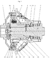
- Fig. 1
- eine erfindungsgemäße Kupplung in einer Querschnittdarstellung;
- Fig. 2
- eine Detailvergrößerung einer erfindungsgemäßen Kupplung mit einer bevorzugten Position eines Temperaturüberwachungsmittels;
- Fig. 3
- eine Detailvergrößerung einer erfindungsgemäßen Kupplung mit einer bevorzugten Position eines Drucküberwachungsmittels und eines Reibbelagsverschleißüberwachungsmittels bzw. Weg-, Abstand- und/oder Positionsüberwachungsmittels;
- Fig. 4
- eine Detailvergrößerung einer erfindungsgemäßen Kupplung mit einer bevorzugten Position eines Reibbelagsverschleißüberwachungsmittels bzw. Weg-, Abstand- und/oder Positionsüberwachungsmittels;
- Fig. 5
- eine Detailvergrößerung einer erfindungsgemäßen Kupplung mit einer bevorzugten Position eines Drehmomentüberwachungsmittels;
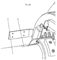
- Fig. 5a
- eine Detailvergrößerung einer erfindungsgemäßen Kupplung mit einer bevorzugten Position eines Drehmomentüberwachungsmittels;
- Fig. 6
- eine erfindungsgemäße Kupplung in einer perspektivischen Ansicht mit Komponenten einer Datenübertragungseinrichtung;
- Fig. 7
- eine erfindungsgemäße Kupplung in einer perspektivischen Ansicht mit Komponenten einer Datenübertragungseinrichtung;
- Fig. 7a
- eine erfindungsgemäße Kupplung in einer perspektivischen Ansicht mit Komponenten einer Datenübertragungseinrichtung;
- Fig. 8
- eine erfindungsgemäße Kupplungsanordnung;
- Fig. 9
- eine erfindungsgemäße Arbeitsmaschine.
- Folgende Bezugszeichen werden in den Abbildungen verwendet:
- K
- Kupplung
- 1
- Eingangswelle
- 2
- Ausgangswelle
- 3
- Kupplungsmittel
- 4
- Schaltmittel
- 5
- Gehäuse / Maschinenrahmen
- 6
- Temperaturüberwachungsmittel
- 7
- Drucküberwachungsmittel
- 8
- Drehmomentüberwachungsmittel
- 9
- Reibbelagsverschleißüberwachungsmittel
- 10
- Sensorsignalverstärker
- 11
- Datenübertragungseinrichtung
- 12
- Weg-, Abstand- und/oder Positionsüberwachungsmittel
- 13
- Auswerteeinrichtung
- 14
- Antriebsmittel
- 15
- Arbeitsmittel
- 31
- erste Druckscheibe
- 32
- zweite Druckscheibe
- 33
- Bolzen
- 34
- Öffnung
- 35
- Feder
- 36
- Zahnkranz
- 37
- Kupplungsscheibe
- 38
- Innenscheibe
- 39
- Öffnung
- 41
- Zylinder
- 42
- Kolben
- 91
- Träger
- 92
- Gleitkontakt
- 111
- Induktive Datenübertragung- und Stromversorgungsmittel
- 112
- Datenübertragungsmittel
- 113
- induktive Stromversorgung
- 114
- Gebermodul
- 115
- Antenne
- 116
- Hochfrequenzkabel
- 117
- Steckverbindung
- Eine Kupplung, insbesondere eine schaltbare und fremdbetätigte Kupplung, umfasst im Wesentlichen ein Drehmomenteingangsmittel 1, ein Drehmomentausgangsmittel 2, ein Kupplungsmittel 3, ein Schaltmittel 4 und vorzugsweise ein Gehäuse oder Maschinenrahmen 5.
- Das Drehmomenteingangsmittel, als auch das Drehmomentausgangsmittel kann beispielsweise als Welle, Hohlwelle, Flansch, etc. ausgestaltet sein. Im Wesentlichen sollen die vorgenannten Mittel dazu eingerichtet sein, ein Drehmoment in die Kupplung einzuleiten bzw. abzuleiten. Als Synonym für das Drehmomenteingangsmittel bzw. Drehmomentausgangsmittel soll nachfolgend von Eingangswelle 1 und Ausgangswelle 2 gesprochen werden.
- Das Kupplungsmittel 3 ist zwischen der Eingangswelle 1 und der Ausgangswelle 2 angeordnet. Das Kupplungsmittel 3 ist dazu eingerichtet, den Drehmomentfluss zwischen der Eingangswelle 1 und der Ausgangswelle 2 wahlweise ein- oder auszuschalten. Je nach Bauweise des Kupplungsmittels 3 sind auch Drehmomentreduzierungen, beispielsweise eine schleifendes oder rutschendes Kupplungsmittel, möglich.
- Das Kupplungsmittel 3 kann beispielsweise eine erste Druckscheibe 31 und eine zweite Druckscheibe 32 umfassen, wobei die erste Druckscheibe 31 beispielsweise fest mit der Ausgangswelle 2 verbunden ist und die zweite Druckscheibe 32 axial verschiebbar auf der Ausgangswelle 2 aufgenommen ist. Zudem kann die erste Druckscheibe 31 mit mindestens einem axial ausgerichteten Bolzen 33, vorzugsweise mehreren Bolzen, und die zweite Druckscheibe mit mindestens einer korrespondierenden Öffnung 34, vorzugsweise mehreren Öffnungen, für die Bolzen ausgestattet sein. Auch kann mindestens eine Feder 35, vorzugsweise mehrere Federn, zwischen den Druckscheiben 31, 32 angeordnet sein.
- Ferner kann das Kupplungsmittel einen Zahnkranz 36 und mindestens eine, vorzugsweise auch mehrere Kupplungsscheiben 37 umfassen, wobei der Zahnkranz 36 fest mit der Eingangswelle 1 verbunden ist und die Kupplungsscheibe 37 axial verschiebbar, beispielsweise über eine Schiebeverzahnung, in dem Zahnkranz 36 aufgenommen ist.
- Die Kupplungsscheibe 37 ist zwischen der ersten Druckscheibe 31 und der zweiten Druckscheibe 32 aufgenommen. Die Kupplungsscheibe 37 ist in der Regel mit einem Reibbelag zur Erreichung eines hohen Reibwertes ausgestattet. Es können auch mehrere Kupplungsscheiben 37 vorgesehen sein, wobei in diesem Fall vorzugsweise zwischen zwei Kupplungsscheiben je eine Innenscheibe 38 vorgesehen ist. Die Innenscheibe 38 ist vorzugsweise axial verschiebbar auf der Ausgangswelle 2 aufgenommen. Vorzugsweise weist die Innenscheibe 38 Öffnungen 39 auf, durch welche die Bolzen 33 hindurchragen können.
- Das Schaltmittel 4 kann beispielsweise als Zylinder-Kolben-Kombination, umfassend einen Zylinder 41 und einen Kolben 42, ausgestaltet sein, welche hydraulisch betrieben wird. Denkbar sind aber auch weitere geeignete Schaltmittel, beispielsweise auf mechanischer, elektrischer und/oder pneumatischer Basis.
- Über das Schaltmittel 4 bzw. den Kolben 42 kann die zweite Druckscheibe 32 verschoben werden, so dass die Kupplungsscheibe 37 bzw. die Kupplungsscheiben wahlweise einen Reibschluss mit den den Druckscheiben 31, 32 bzw. den Innenscheiben 38 eingehen oder nicht. Anders ausgedrückt das Schaltmittel schaltet die Kupplung ein oder aus.
- In der Regel ist die Feder 35 zwischen den Druckscheiben 31, 32 vorgesehen, welche die Druckscheiben auseinanderdrückt. In einem Ausgangszustand ist die Kupplung geöffnet und wird durch Betätigung des Schaltmittels 4 geschlossen. Es ist aber auch der andere Fall denkbar, dass die Druckscheiben 31, 32 beispielsweise über eine Tellerfeder (nicht dargestellt) zusammengedrückt werden und das Schaltmittel die Kupplung öffnet.
- Die Ausführungsmöglichkeiten der Kupplung sind überaus zahlreich, dem Fachmann jedoch hinreichend bekannt.
- Es ist ferner vorzugsweise vorgesehen, dass die Kupplung ein Gehäuse 5 oder Maschinenrahmen umfasst, das bzw. der in der Regel ortsfest angebracht ist. In den hier vorliegenden Abbildungen ist lediglich ein Halter dargestellt, der letztendlich ortsfest an dem Gehäuse oder Maschinenrahmen angebracht ist.
- Erfindungsgemäß ist vorgesehen, dass die Kupplung mit mindestens einem Zustandsüberwachungsmittel ausgestattet ist.
- Das Zustandsüberwachungsmittel ist grundsätzlich dazu eingerichtet, den Zustand einzelner Komponenten der Kupplung zu detektieren. Das Zustandsüberwachungsmittel kann auch als Sensor angesprochen werden. Hier sind verschiedene Ansätze denkbar.
- Als bevorzugte Zustandsüberwachungsmittel kommen insbesondere Temperaturüberwachungsmittel 6, Drucküberwachungsmittel 7, Reibbelagsverschleißüberwachungsmittel 8 und / oder Drehmomentüberwachungsmittel 9 in Frage. Auch Weg-, Abstand- und/oder Positionsüberwachungsmittel 12 sind denkbar.
- Bei dem Temperaturüberwachungsmittel 6 kann es sich beispielsweise um ein Widerstandsthermometer, ein Thermoelement, ein Infrarot-Thermometer und/oder ein Thermometer handeln. Ein Thermoelement umfasst ein Paar metallischer Leiter aus unterschiedlichem Material, die an einem Ende verbunden sind und aufgrund des thermoelektrischen Effektes zur Temperaturmessung geeignet sind.
- Bei dem Drucküberwachungsmittel 7 kann es sich beispielsweise um einen induktiven Drucksensor, piezoresistiven Drucksensor, einen kapazitiven Drucksensor und/oder einen Drucksensor mit Hallelement handeln.
- Bei dem Drehmomentüberwachungsmittel 8 kann es sich beispielsweise um einen Dehnungsmessstreifen, einen Kraftsensor und/oder einen auf Magnetostriktion beruhenden Sensor handeln.
- Bei dem Reibbelagsverschleißüberwachungsmittel 9 kann es sich beispielsweise um einen induktiven Wegaufnehmer, einen kapazitiven Wegaufnehmer, ein Potentiometer, eine Messunterlegscheibe, eine optische Distanzmessung und/oder ein mechanisches System handeln.
- Bei dem Weg-, Abstand- und/oder Positionsüberwachungsmittel 12 kann es sich um einen induktiven Wegaufnehmer, einen kapazitiven Wegaufnehmer, ein Potentiometer, eine Messunterlegscheibe, eine optische Distanzmessung und/oder ein mechanisches System handeln. Das Reibbelagsverschleißüberwachungsmittel 9 kann gleichzeitig ein Weg-, Abstand- und/oder Positionsüberwachungsmittel 12 sein bzw. vice versa.
- Zur Übertragung der von den Zustandsüberwachungsmitteln detektierten Daten kann die Kupplung mit jeweils zugeordneten Übertragungsmitteln ausgestattet sein.
- Das Übertragungsmittel kann beispielsweise auf den Prinzipien SAW, Telemetrie und/oder Funk beruhen. Entsprechend kann es sich bei dem Übertragungsmittel beispielsweise um SAW-, Telemetrie und/oder Funkmittel handeln.
- Das Zustandsüberwachungsmittel und das Übertragungsmittel können in einem gemeinsamen Gehäuse untergebracht sein.
- Als mögliche Montagepositionen für die einzelnen Zustandsüberwachungsmittel kommen unterschiedliche Stellen der Kupplung in Frage.
- So kann beispielsweise vorgesehen sein, dass das Temperaturüberwachungsmittel 6 auf der Innenscheibe 38, insbesondere auf der hinteren, der vom Kolben am weitesten entfernten Innenscheibe, angebracht ist. Hier sind die höchsten Temperaturen in der Kupplung zu erwarten, so dass die Temperaturmessung an dieser Stelle besonders aussagekräftig ist. Auch sind Temperaturüberwachungsmittel auf Infrarot Basis denkbar, welche Temperaturen der Kupplungsbauteile sogar von außen, sprich ohne direkten Kontakt, detektieren können. Die Temperaturmessung erfolgt letztendlich berührungslos und es sind spezielle Ausführungen für explosionsgefährdete Bereiche verfügbar. Das auf Infrarot basierende Temperaturüberwachungsmittel stellt eine kostengünstige Lösung dar und ist für explosionsgefährdete Bereiche zertifiziert.
- Es kann ferner vorgesehen sein, dass das Drucküberwachungsmittel 7 an die Zylinder-Kolben-Kombination angeschlossen ist, insbesondere mit dem Zylinder 41 in einer zur Druckübertragung geeigneten Verbindung steht.
- So kann ferner vorgesehen sein, dass das Drehmomentüberwachungsmittel 8 dem Drehmomenteingangsmittel 1 und/oder Drehmomentausgangsmittel 2 verbunden ist, insbesondere, dass das Drehmomentüberwachungsmittel als Dehnungsmesstreifen ausgestaltet ist und dass der Dehnungsmessstreifen auf dem als Eingangswelle 1 bzw. Ausgangswelle 2 ausgestalteten Drehmomenteingangsmittel bzw. Drehmomentausgangsmittel aufgebracht ist. Vorzugsweise werden die auftretenden Drehmomente in Echtzeit gemessen. Das Drehmomentüberwachungsmittel 8 kann auch auf der Eingangswelle 1 bzw. Ausgangswelle 2 vergossen sein, damit es für eine raue Umgebung geeignet ist. Soweit die Kupplung in einer Arbeitsmaschine verbaut ist, wird eine Drehmomentmessung direkt am Hauptantriebsstrang der Arbeitsmaschine ermöglicht.
- Es kann ferner vorgesehen sein, dass das Reibbelagsverschleißüberwachungsmittel 9 an dem Gehäuse 5 bzw. Maschinenrahmen angebracht ist. Im Wesentlichen kann das Reibbelagsverschleißüberwachungsmittel dazu eingerichtet sein, den Abstand zwischen sich und der zweiten Druckscheibe 32 und/oder den Abstand der Druckscheiben 31, 32 zu messen, woraus dann letztendlich auf die Dicke der Kupplungsscheiben 37 ggf. auch der Druckscheiben 31, 32 und/oder Innenscheiben 38 geschlossen werden kann.
- So kann ferner vorgesehen sein, dass das Reibbelagsverschleißüberwachungsmittel 9 ein an dem Zylinder und ein an der zweiten Druckscheibe angebrachtes Element umfasst. So kann beispielsweise das Reibbelagsverschleißüberwachungsmittel als Potentiometer ausgestaltet sein, umfassend einen elektrisch nichtleitenden Träger 91, auf dem ein Widerstandsmaterial aufgebracht ist, und einen Gleitkontakt 92. Der Träger kann beispielsweise auf dem Zylinder 41 angebracht sein und der Gleitkontakt entsprechend mit der zweiten Druckscheibe 32 verbunden sein. Diese Anordnung lässt sich entsprechend auch vice versa ausgestalten.
- Grundsätzlich sind auch weitere Zustandsüberwachungsmittel denkbar, wie beispielsweise ein Drehzahlüberwachungsmittel, Mittel zur Überwachung der Schwingungen, sprich Schwingungsmessung um beispielsweise Lagerschäden oder Verzahnungsschäden im Vorfeld zu einem Ausfall zu detektieren.
- Die einzelnen Zustandsüberwachungsmittel können mit Sensorsignalverstärkern 10 ausgestattet sein, um die jeweiligen Signale in geeigneter Weise zu verstärken.
- Zur Übertragung der durch die Zustandsüberwachungsmittel detektierten Zustände ist vorzugsweise eine Datenübertragungseinrichtung 11 vorgesehen.
- Als Prinzipien für die Datenübertragungseinrichtung kommen beispielsweise Nahfeldtelemetrie per Funk, Surface Acoustic Wave (SAW) oder auch alternative Systeme in Frage.
- Bei der Nahfeldtelemetrie wird die Übertragung der Messdaten mittels Funk gewährleistet. Die Datenübertragung kann von der rotierenden auf die ortsfeste Seite der Kupplung erfolgen. Die Stromversorgung auf die rotierende Seite kann mittels Induktion erfolgen. Die Datenübertragung kann via Funk oder Induktion erfolgen. Es werden grundsätzlich alle Arten passiver Sensoren unterstützt. Ein auf Nahfeldtelemetrie basierendes System stellt ein an die Messaufgabe angepasstes System dar. Grundsätzlich umfasst ein auf Nahfeldtelemetrie basierendes System für den Dauereinsatz konzipierte Komponenten auf. Ein auf Nahfeldtelemetrie basierendes System ist sehr flexibel anpassbar.
- So kann die Datenübertragungseinrichtung in Form eines auf Nahfeldtelemetrie basierendes System beispielsweise eine ortsfeste Anordnung und ein den drehenden Komponenten der Kupplung zugeordnete Anordnung umfassen.
- Die ortsfeste Anordnung kann beispielsweise ein induktives Datenübertragungs- und Stromversorgungsmittel 111 umfassen. Die den drehenden Komponenten der Kupplung zugeordnete Anordnung kann ein induktives Datenübertragungsmittel 112, eine induktive Stromversorgung 113 und ein Gebermodul 114 umfassen. Das induktive Datenübertragungs- und Stromversorgungsmittel 111 ist vorzugsweise an dem ortsfesten Gehäuse 5 bzw. Maschinenrahmen angebracht, während das induktive Datenübertragungsmittel 112, die induktive Stromversorgung 113 und das Gebermodul 114 insbesondere an einem drehenden Element der Kupplung, beispielsweise außen an dem Zylinder 41 angebracht ist.
- Bei einer auf Surface Acoustic Wave (SAW) basierenden Datenübertragungseinrichtung werden die SAW-Elemente von außen über Funk angeregt, worauf sie mit einem spezifischen Signal antworten, vergleichbar mit einem Echo. Die durch den Sendeimpuls zugeführte Energie reicht für eine Antwort des Elementes aus, vergleichbar mit radio-frequency identification (RFID). Eine auf Surface Acoustic Wave (SAW) basierenden Datenübertragungseinrichtung weist vorteilhafterweise eine geringe Komplexität sowie einfache Bauteile auf. Es ist ferner relativ unempfindlich gegenüber äußeren Einflüssen und vergleichsweise günstig.
- Eine auf SAW basierenden Datenübertragungseinrichtung kann beispielsweise eine Antenne 115 bzw. Antennen, ein Hochfrequenzkabel 116, eine Steckverbindung 117 und ein Zustandsüberwachungsmittel umfassen. Das Zustandsüberwachungsmittel kann beispielsweise als Temperaturüberwachungsmittel ausgestaltet sein und an der Innenscheibe angebracht sein.
- Eine ebenfalls erfindungsgemäße Kupplungsanordnung umfasst im Wesentlichen eine erfindungsgemäße Kupplung und eine Auswerteeinrichtung.
- Die von den Zustandsüberwachungsmitteln ermittelten Daten bzw. die von der Datenübertragungseinrichtung übermittelten Daten werden an die Auswerteeinrichtung (13), beispielsweise einen Computer, geschickt. Hier können die Daten entsprechend ausgewertet werden. Der Computer ist hierzu mit einer geeigneten Software ausgestattet.
- Ferner kann die erfindungsgemäße Kupplungsanordnung bzw. Kupplung in eine Arbeitsmaschine, beispielsweise einen Extruder, einen Schiffsantrieb oder eine Straßenbaumaschine, integriert werden. Eine entsprechende Arbeitsmaschine umfasst entsprechend ein Antriebsmittel, beispielsweise einen Diesel- oder Elektromotor, die erfindungsgemäße Kupplungsanordnung bzw. Kupplung und ein drehend angetriebenes Arbeitsmittel, beispielsweise das Zerkleinerungswerk einer Straßenbaumaschine, den Antrieb eines Schiffes oder den Schneckenförderer eines Extruders.
- So kann beispielsweise die Temperaturmessung durch die Temperaturüberwachungsmittel 6 eine sinnvolle Ergänzung einer bestehenden Schlupfüberwachung darstellen, insbesondere können die durch Mikroschlupf verursachten Temperaturen sicher überwacht werden. Mit anderen Worten, ist die Auswerteeinrichtung dazu eingerichtet, aus den Daten des Temperaturüberwachungsmittels 6 eine Überwachung des Schlupfes der Kupplung, insbesondere des Mikroschlupfes, zu generieren.
- Es kann ferner über die von dem Reibbelagsverschleißüberwachungsmittel 9 gelieferten Daten eine Verschleißmessung der Kupplungsscheiben 37 vorgenommen werden. Mit den Daten der Reibbelagsverschleißüberwachungsmittel 9 kann eine zustandsorientierte Instandhaltung vorgenommen werden. Die Verschleißmessung kann beispielsweise wie folgt erfolgen. Mit dem beispielsweise als Wegaufnehmer ausgestalteten Reibbelagsverschleißüberwachungsmittel 9 wird der Weg beim Schalten der Kupplung gemessen. Bei der Inbetriebnahme der Kupplung bzw. der Maschine, in welcher die Kupplung verbaut ist, wird ein Referenzwert = Ursprungswert ausfallsicher und dauerhaft in der Auswerteeinrichtung bzw. Maschinensteuerung gespeichert. Bei jedem Schaltvorgang wird der Weg gemessen und mit dem Ursprungswert verglichen. Bei Erreichen des maximal zulässigen Weges bekommt der Maschinenbediener eine Meldung, dass der Verschleiß der Kupplungsscheiben 37 erreicht ist und die Kupplungsscheiben ausgewechselt werden müssen. Nach dem Austausch der Kupplungsscheiben sollte bzw. muss der Ursprungswert neu eingestellt werden. Letztendlich ist die Auswerteeinrichtung in diesem Zusammenhang dazu eingerichtet, einen Instandhaltungsplan in Abhängigkeit von dem tatsächlichen Verschleißzustand der Kupplungsscheiben zu generieren.
- Aus dem Einsatz des Reibbelagsverschleißüberwachungsmittels bzw. der Auswertung der gelieferten Daten in der Auswerteeinrichtung ergeben sich einige Vorteile. So entsteht kein manueller Inspektionsaufwand, um den Verschleißzustand der Kupplungsscheiben zu ermitteln. Die Beschaffung der Kupplungsscheiben kann rechtzeitig und geplant erfolgen. Ungeplante Stillstandzeiten durch unerwarteten Ausfall der Kupplungsscheiben im Fall von mangelnder Wartung bzw. Inspektion kann vermieden werden. Wartungs- oder Inspektionsintervalle werden besser planbar. Es wird die Möglichkeit von "Condition Monitoring" (vorbeugende Instandhaltung bzw. kontinuierliche Zustandsüberwachung) eröffnet.
- Über die von den Drehmomentüberwachungsmittel 8 gelieferten Daten kann das gemessene Drehmoment zur Optimierung oder Regelung der Maschinenauslastung genutzt werden. Insbesondere kann eine Optimierung des Betriebspunktes eines Dieselmotors in Abhängigkeit der tatsächlichen Leistung im Hauptantriebsstrang vorgenommen werden, sofern die Kupplung entsprechend in einer Arbeitsmaschine verbaut ist, die von einem Dieselmotor angetrieben wird. Es wird die Möglichkeit zur Erstellung einer Belastungshistorie eröffnet. Es wird die Möglichkeit von "Condition Monitoring" eröffnet.
Claims (15)
- Kupplung (K), insbesondere eine schaltbare und fremdbetätigte Kupplung, umfassend- ein Drehmomenteingangsmittel (1), ein Drehmomentausgangsmittel (2), ein Kupplungsmittel (3) und ein Schaltmittel (4),dadurch gekennzeichnet, dass
die Kupplung mit mindestens einem Zustandsüberwachungsmittel ausgestattet ist. - Kupplung nach Anspruch 1, dadurch gekennzeichnet, dass das Zustandsüberwachungsmittel als- Temperaturüberwachungsmittel (6),- Drucküberwachungsmittel (7),- Drehmomentüberwachungsmittel (8),- Reibbelagsverschleißüberwachungsmittel (9),- Drehzahlüberwachungsmittel- Schwingungsüberwachungsmittel und/oder- Weg-, Abstand- und/oder Positionsüberwachungsmittel (12) ausgestaltet ist.
- Kupplung nach mindestens einem der vorhergehenden Ansprüche, dadurch gekennzeichnet, dass das Drehmomenteingangsmittel (1) und/oder das Drehmomentausgangsmittel (2) als Welle, Hohlwelle oder Flansch ausgestaltet ist.
- Kupplung nach mindestens einem der vorhergehenden Ansprüche, dadurch gekennzeichnet, dass- das Kupplungsmittel eine erste Druckscheibe (31) und eine zweite Druckscheibe (32) umfasst, wobei- die erste Druckscheibe 31 fest mit dem Drehmomentausgangsmittel (2) verbunden ist und die zweite Druckscheibe (32) axial verschiebbar auf dem Drehmomentausgangsmittel (2) aufgenommen ist,- wobei das Kupplungsmittel einen Zahnkranz 36 und mindestens eine, vorzugsweise auch mehrere Kupplungsscheiben (37) umfasst, wobei der Zahnkranz (36) fest mit dem Drehmomenteingangsmittel (1)verbunden ist und die Kupplungsscheibe (37) axial verschiebbar, beispielsweise über eine Schiebeverzahnung, in dem Zahnkranz (36) aufgenommen ist, wobei- die mindestens eine Kupplungsscheibe (37) zwischen der ersten Druckscheibe (31) und der zweiten Druckscheibe (32) aufgenommen ist, wobei- die Kupplung mit einem Schaltmittel (4) ausgestattet ist, welches zur Bewegung der zweiten Druckscheibe (32) eingerichtet ist.
- Kupplung nach mindestens einem der vorhergehenden Ansprüche, dadurch gekennzeichnet, dass die Kupplung mit mindestens einer Innenscheibe (38) ausgestattet ist, die jeweils zwischen zwei Kupplungsscheiben (37) angeordnet ist und axial verschiebbar auf dem Drehmomentausgangsmittel (2) aufgenommen ist.
- Kupplung nach mindestens einem der vorhergehenden Ansprüche, dadurch gekennzeichnet, dass das Schaltmittel (4) als Zylinder-Kolben-Anordnung ausgestaltet ist, umfassend einen Zylinder (41) und einen Kolben (42).
- Kupplung nach mindestens einem der vorhergehenden Ansprüche, dadurch gekennzeichnet, dass die Kupplung mit einem ortsfesten Gehäuse oder Maschinenrahmen (5) ausgestattet ist.
- Kupplung nach mindestens einem der vorhergehenden Ansprüche, dadurch gekennzeichnet, dass das Temperaturüberwachungsmittel (6) an der Innenscheibe (38), insbesondere an der von dem Kolben (42) am weitesten entfernten Innenscheibe (38), angebracht ist.
- Kupplung nach mindestens einem der vorhergehenden Ansprüche, dadurch gekennzeichnet, dass die Kupplung mit einer Datenübertragungseinrichtung (11) ausgestattet ist.
- Kupplungsanordnung, umfassend eine Kupplung (K) und eine Auswerteeinrichtung (13), dadurch gekennzeichnet, dass es sich um eine Kupplung (K) gemäß mindestens einem der Ansprüche 1 bis 9 handelt.
- Kupplungsanordnung nach Anspruch 10, dadurch gekennzeichnet, dass die Auswerteeinrichtung (13) dazu eingerichtet ist, aus den Daten des Reibbelagsverschleißüberwachungsmittels (9) einen Instandhaltungsplan in Abhängigkeit von dem tatsächlichen Verschleißzustand der Kupplungsscheiben (37) zu generieren.
- Kupplungsanordnung nach mindestens einem der vorhergehenden Ansprüche, dadurch gekennzeichnet, dass die Auswerteeinrichtung (13) dazu eingerichtet ist, aus den Daten des Temperaturüberwachungsmittels (6) eine Überwachung des Schlupfes der Kupplung, insbesondere des Mikroschlupfes, vorzunehmen.
- Kupplungsanordnung nach mindestens einem der vorhergehenden Ansprüche, dadurch gekennzeichnet, dass die Auswerteeinrichtung (13) dazu eingerichtet ist, aus den Daten des mittels des Drehmomentüberwachungsmittels (8) gemessenen Drehmoment eine Optimierung der Auslastung eines Antriebsmittel (14) einer Arbeitsmaschine vorzunehmen.
- Arbeitsmaschine, insbesondere Extruder, Schiffsantrieb oder Straßenbaumaschine, umfassend ein Antriebsmittel (14), eine Kupplungsanordnung und ein Arbeitsmittel (15), dadurch gekennzeichnet, dass es sich um eine Kupplungsanordnung gemäß mindestens einem der Ansprüche 10 bis 13 handelt.
- Arbeitsmaschine nach Anspruch 14, dadurch gekennzeichnet, dass das es sich bei dem Arbeitsmittel (15) um das Zerkleinerungswerk einer Straßenbaumaschine, den Antrieb eines Schiffes oder den Schneckenförderer eines Extruders handelt.
Applications Claiming Priority (2)
| Application Number | Priority Date | Filing Date | Title |
|---|---|---|---|
| DE102015107932 | 2015-05-20 | ||
| DE102016106367 | 2016-04-07 |
Publications (2)
| Publication Number | Publication Date |
|---|---|
| EP3096039A1 true EP3096039A1 (de) | 2016-11-23 |
| EP3096039B1 EP3096039B1 (de) | 2020-08-26 |
Family
ID=56026754
Family Applications (1)
| Application Number | Title | Priority Date | Filing Date |
|---|---|---|---|
| EP16170590.0A Active EP3096039B1 (de) | 2015-05-20 | 2016-05-20 | Kupplung, kupplungsanordnung und arbeitsmaschine |
Country Status (2)
| Country | Link |
|---|---|
| EP (1) | EP3096039B1 (de) |
| ES (1) | ES2824491T3 (de) |
Citations (5)
| Publication number | Priority date | Publication date | Assignee | Title |
|---|---|---|---|---|
| GB2324583A (en) * | 1994-02-23 | 1998-10-28 | Luk Getriebe Systeme Gmbh | Electrical clutch control system |
| EP1559922B1 (de) | 2004-01-28 | 2007-11-28 | Desch Antriebstechnik GmbH & Co. KG | Kupplung |
| DE102007034203A1 (de) * | 2006-08-17 | 2008-02-21 | Luk Lamellen Und Kupplungsbau Beteiligungs Kg | Verfahren und Vorrichtung zur Erkennung von Kupplungsverschleiß |
| FR2907867A1 (fr) * | 2006-10-25 | 2008-05-02 | Peugeot Citroen Automobiles Sa | Systeme et procede d'estimation d'un couple transmis par un embrayage a friction de vehicule automobile |
| FR2908484A1 (fr) * | 2006-11-10 | 2008-05-16 | Peugeot Citroen Automobiles Sa | Procede et systeme de diagnostic de l'etat de fonctionnement d'un embrayage a friction seche de vehicule automobile. |
-
2016
- 2016-05-20 EP EP16170590.0A patent/EP3096039B1/de active Active
- 2016-05-20 ES ES16170590T patent/ES2824491T3/es active Active
Patent Citations (5)
| Publication number | Priority date | Publication date | Assignee | Title |
|---|---|---|---|---|
| GB2324583A (en) * | 1994-02-23 | 1998-10-28 | Luk Getriebe Systeme Gmbh | Electrical clutch control system |
| EP1559922B1 (de) | 2004-01-28 | 2007-11-28 | Desch Antriebstechnik GmbH & Co. KG | Kupplung |
| DE102007034203A1 (de) * | 2006-08-17 | 2008-02-21 | Luk Lamellen Und Kupplungsbau Beteiligungs Kg | Verfahren und Vorrichtung zur Erkennung von Kupplungsverschleiß |
| FR2907867A1 (fr) * | 2006-10-25 | 2008-05-02 | Peugeot Citroen Automobiles Sa | Systeme et procede d'estimation d'un couple transmis par un embrayage a friction de vehicule automobile |
| FR2908484A1 (fr) * | 2006-11-10 | 2008-05-16 | Peugeot Citroen Automobiles Sa | Procede et systeme de diagnostic de l'etat de fonctionnement d'un embrayage a friction seche de vehicule automobile. |
Also Published As
| Publication number | Publication date |
|---|---|
| ES2824491T3 (es) | 2021-05-12 |
| EP3096039B1 (de) | 2020-08-26 |
Similar Documents
| Publication | Publication Date | Title |
|---|---|---|
| EP2057386B1 (de) | TEMPERATUR- UND VERSCHLEIßSENSOR FÜR BREMS- ODER KUPPLUNGSEINRICHTUNGEN | |
| EP3126810B1 (de) | Riemenantrieb und verfahren zum überwachen eines solchen riemenantriebs | |
| EP3766646B1 (de) | Zykloidgetriebe mit drehmomenterfassungseinrichtung | |
| EP1955796B1 (de) | Maschinenspindel mit einer Spannvorrichtung | |
| WO2015149775A1 (de) | Modulares aktorkonzept für kupplungsaktor | |
| DE102017107982A1 (de) | Bremsanlagen-telemetriesysteme und verfahren | |
| EP3268635B1 (de) | Planetengetriebe | |
| DE102005038663A1 (de) | Rundschalttisch | |
| EP1365167B1 (de) | Vorrichtung zum wahlweise Aus- bzw. Einrücken einer Reibkupplung für Kraftfahrzeuge | |
| WO2014023278A1 (de) | Nichtschaltbare kupplung mit drehmomentüberwachung | |
| EP3096039B1 (de) | Kupplung, kupplungsanordnung und arbeitsmaschine | |
| EP3313165B1 (de) | Antriebsstrang mit angetriebener welle, magnetostriktiver drehmomentmessung und integriertem freilauf | |
| WO2018215205A1 (de) | Antriebsstrang mit thermischer überlastsicherung | |
| DE102012220073A1 (de) | Elektromechanisches Kupplungsbetätigungssystem und Verfahren zum Ansteuern einer Kupplung | |
| DE102004003287A1 (de) | Kupplungsanordnung | |
| EP4490416B1 (de) | Antriebssystem mit planetengetriebe | |
| EP2893214B1 (de) | Drehmomentübertragungseinrichtung mit belastungsanzeiger | |
| DE19835334C2 (de) | Antriebsstrang für ein unter Tage eingesetztes Betriebsmittel mit umlaufendem Kettenstrang | |
| EP3032233A1 (de) | Vorrichtung zur Drehmomentbestimmung sowie Antrieb zum Betätigen eines Maschinenelements | |
| EP1931892B1 (de) | Drehschwingungsdämpfer mit einer elastischen kupplung | |
| DE3441428A1 (de) | Antriebssystem fuer ueberlastgefaehrdete anlagen bei einfach- und mehrfachantrieb | |
| DE102014204392A1 (de) | System und Verfahren zur Ermittlung von Messgrößen an einem rotierenden Bauteil | |
| EP1931890A1 (de) | Lebensdauerüberwachungssystem | |
| EP3507192B1 (de) | Antriebsanordnung für ein schiff mit mittel zur zustandsüberwachung | |
| WO2018219642A1 (de) | Bürste für eine elektrische maschine, insbesondere eines kraftfahrzeugs, sowie verfahren zum ermitteln eines verschleisses einer solchen bürste |
Legal Events
| Date | Code | Title | Description |
|---|---|---|---|
| PUAI | Public reference made under article 153(3) epc to a published international application that has entered the european phase |
Free format text: ORIGINAL CODE: 0009012 |
|
| AK | Designated contracting states |
Kind code of ref document: A1 Designated state(s): AL AT BE BG CH CY CZ DE DK EE ES FI FR GB GR HR HU IE IS IT LI LT LU LV MC MK MT NL NO PL PT RO RS SE SI SK SM TR |
|
| AX | Request for extension of the european patent |
Extension state: BA ME |
|
| STAA | Information on the status of an ep patent application or granted ep patent |
Free format text: STATUS: REQUEST FOR EXAMINATION WAS MADE |
|
| 17P | Request for examination filed |
Effective date: 20170523 |
|
| RBV | Designated contracting states (corrected) |
Designated state(s): AL AT BE BG CH CY CZ DE DK EE ES FI FR GB GR HR HU IE IS IT LI LT LU LV MC MK MT NL NO PL PT RO RS SE SI SK SM TR |
|
| STAA | Information on the status of an ep patent application or granted ep patent |
Free format text: STATUS: EXAMINATION IS IN PROGRESS |
|
| 17Q | First examination report despatched |
Effective date: 20190717 |
|
| GRAP | Despatch of communication of intention to grant a patent |
Free format text: ORIGINAL CODE: EPIDOSNIGR1 |
|
| STAA | Information on the status of an ep patent application or granted ep patent |
Free format text: STATUS: GRANT OF PATENT IS INTENDED |
|
| INTG | Intention to grant announced |
Effective date: 20200320 |
|
| GRAS | Grant fee paid |
Free format text: ORIGINAL CODE: EPIDOSNIGR3 |
|
| GRAA | (expected) grant |
Free format text: ORIGINAL CODE: 0009210 |
|
| STAA | Information on the status of an ep patent application or granted ep patent |
Free format text: STATUS: THE PATENT HAS BEEN GRANTED |
|
| AK | Designated contracting states |
Kind code of ref document: B1 Designated state(s): AL AT BE BG CH CY CZ DE DK EE ES FI FR GB GR HR HU IE IS IT LI LT LU LV MC MK MT NL NO PL PT RO RS SE SI SK SM TR |
|
| REG | Reference to a national code |
Ref country code: GB Ref legal event code: FG4D Free format text: NOT ENGLISH |
|
| REG | Reference to a national code |
Ref country code: CH Ref legal event code: EP |
|
| REG | Reference to a national code |
Ref country code: DE Ref legal event code: R096 Ref document number: 502016010927 Country of ref document: DE |
|
| REG | Reference to a national code |
Ref country code: AT Ref legal event code: REF Ref document number: 1306667 Country of ref document: AT Kind code of ref document: T Effective date: 20200915 |
|
| REG | Reference to a national code |
Ref country code: IE Ref legal event code: FG4D Free format text: LANGUAGE OF EP DOCUMENT: GERMAN |
|
| REG | Reference to a national code |
Ref country code: FI Ref legal event code: FGE |
|
| REG | Reference to a national code |
Ref country code: NL Ref legal event code: FP |
|
| REG | Reference to a national code |
Ref country code: SE Ref legal event code: TRGR |
|
| REG | Reference to a national code |
Ref country code: NO Ref legal event code: T2 Effective date: 20200826 |
|
| REG | Reference to a national code |
Ref country code: LT Ref legal event code: MG4D |
|
| PG25 | Lapsed in a contracting state [announced via postgrant information from national office to epo] |
Ref country code: LT Free format text: LAPSE BECAUSE OF FAILURE TO SUBMIT A TRANSLATION OF THE DESCRIPTION OR TO PAY THE FEE WITHIN THE PRESCRIBED TIME-LIMIT Effective date: 20200826 Ref country code: BG Free format text: LAPSE BECAUSE OF FAILURE TO SUBMIT A TRANSLATION OF THE DESCRIPTION OR TO PAY THE FEE WITHIN THE PRESCRIBED TIME-LIMIT Effective date: 20201126 Ref country code: PT Free format text: LAPSE BECAUSE OF FAILURE TO SUBMIT A TRANSLATION OF THE DESCRIPTION OR TO PAY THE FEE WITHIN THE PRESCRIBED TIME-LIMIT Effective date: 20201228 Ref country code: HR Free format text: LAPSE BECAUSE OF FAILURE TO SUBMIT A TRANSLATION OF THE DESCRIPTION OR TO PAY THE FEE WITHIN THE PRESCRIBED TIME-LIMIT Effective date: 20200826 |
|
| PG25 | Lapsed in a contracting state [announced via postgrant information from national office to epo] |
Ref country code: RS Free format text: LAPSE BECAUSE OF FAILURE TO SUBMIT A TRANSLATION OF THE DESCRIPTION OR TO PAY THE FEE WITHIN THE PRESCRIBED TIME-LIMIT Effective date: 20200826 Ref country code: PL Free format text: LAPSE BECAUSE OF FAILURE TO SUBMIT A TRANSLATION OF THE DESCRIPTION OR TO PAY THE FEE WITHIN THE PRESCRIBED TIME-LIMIT Effective date: 20200826 Ref country code: LV Free format text: LAPSE BECAUSE OF FAILURE TO SUBMIT A TRANSLATION OF THE DESCRIPTION OR TO PAY THE FEE WITHIN THE PRESCRIBED TIME-LIMIT Effective date: 20200826 Ref country code: IS Free format text: LAPSE BECAUSE OF FAILURE TO SUBMIT A TRANSLATION OF THE DESCRIPTION OR TO PAY THE FEE WITHIN THE PRESCRIBED TIME-LIMIT Effective date: 20201226 |
|
| PG25 | Lapsed in a contracting state [announced via postgrant information from national office to epo] |
Ref country code: EE Free format text: LAPSE BECAUSE OF FAILURE TO SUBMIT A TRANSLATION OF THE DESCRIPTION OR TO PAY THE FEE WITHIN THE PRESCRIBED TIME-LIMIT Effective date: 20200826 Ref country code: SM Free format text: LAPSE BECAUSE OF FAILURE TO SUBMIT A TRANSLATION OF THE DESCRIPTION OR TO PAY THE FEE WITHIN THE PRESCRIBED TIME-LIMIT Effective date: 20200826 Ref country code: RO Free format text: LAPSE BECAUSE OF FAILURE TO SUBMIT A TRANSLATION OF THE DESCRIPTION OR TO PAY THE FEE WITHIN THE PRESCRIBED TIME-LIMIT Effective date: 20200826 Ref country code: CZ Free format text: LAPSE BECAUSE OF FAILURE TO SUBMIT A TRANSLATION OF THE DESCRIPTION OR TO PAY THE FEE WITHIN THE PRESCRIBED TIME-LIMIT Effective date: 20200826 Ref country code: DK Free format text: LAPSE BECAUSE OF FAILURE TO SUBMIT A TRANSLATION OF THE DESCRIPTION OR TO PAY THE FEE WITHIN THE PRESCRIBED TIME-LIMIT Effective date: 20200826 |
|
| REG | Reference to a national code |
Ref country code: ES Ref legal event code: FG2A Ref document number: 2824491 Country of ref document: ES Kind code of ref document: T3 Effective date: 20210512 |
|
| REG | Reference to a national code |
Ref country code: DE Ref legal event code: R097 Ref document number: 502016010927 Country of ref document: DE |
|
| PG25 | Lapsed in a contracting state [announced via postgrant information from national office to epo] |
Ref country code: AL Free format text: LAPSE BECAUSE OF FAILURE TO SUBMIT A TRANSLATION OF THE DESCRIPTION OR TO PAY THE FEE WITHIN THE PRESCRIBED TIME-LIMIT Effective date: 20200826 |
|
| PG25 | Lapsed in a contracting state [announced via postgrant information from national office to epo] |
Ref country code: SK Free format text: LAPSE BECAUSE OF FAILURE TO SUBMIT A TRANSLATION OF THE DESCRIPTION OR TO PAY THE FEE WITHIN THE PRESCRIBED TIME-LIMIT Effective date: 20200826 |
|
| PLBE | No opposition filed within time limit |
Free format text: ORIGINAL CODE: 0009261 |
|
| STAA | Information on the status of an ep patent application or granted ep patent |
Free format text: STATUS: NO OPPOSITION FILED WITHIN TIME LIMIT |
|
| 26N | No opposition filed |
Effective date: 20210527 |
|
| PG25 | Lapsed in a contracting state [announced via postgrant information from national office to epo] |
Ref country code: SI Free format text: LAPSE BECAUSE OF FAILURE TO SUBMIT A TRANSLATION OF THE DESCRIPTION OR TO PAY THE FEE WITHIN THE PRESCRIBED TIME-LIMIT Effective date: 20200826 |
|
| PG25 | Lapsed in a contracting state [announced via postgrant information from national office to epo] |
Ref country code: MC Free format text: LAPSE BECAUSE OF FAILURE TO SUBMIT A TRANSLATION OF THE DESCRIPTION OR TO PAY THE FEE WITHIN THE PRESCRIBED TIME-LIMIT Effective date: 20200826 Ref country code: LU Free format text: LAPSE BECAUSE OF NON-PAYMENT OF DUE FEES Effective date: 20210520 |
|
| PGFP | Annual fee paid to national office [announced via postgrant information from national office to epo] |
Ref country code: NL Payment date: 20220519 Year of fee payment: 7 |
|
| PGFP | Annual fee paid to national office [announced via postgrant information from national office to epo] |
Ref country code: SE Payment date: 20220519 Year of fee payment: 7 Ref country code: FR Payment date: 20220524 Year of fee payment: 7 |
|
| PGFP | Annual fee paid to national office [announced via postgrant information from national office to epo] |
Ref country code: FI Payment date: 20220523 Year of fee payment: 7 Ref country code: BE Payment date: 20220519 Year of fee payment: 7 Ref country code: AT Payment date: 20220523 Year of fee payment: 7 |
|
| PG25 | Lapsed in a contracting state [announced via postgrant information from national office to epo] |
Ref country code: HU Free format text: LAPSE BECAUSE OF FAILURE TO SUBMIT A TRANSLATION OF THE DESCRIPTION OR TO PAY THE FEE WITHIN THE PRESCRIBED TIME-LIMIT; INVALID AB INITIO Effective date: 20160520 |
|
| PG25 | Lapsed in a contracting state [announced via postgrant information from national office to epo] |
Ref country code: CY Free format text: LAPSE BECAUSE OF FAILURE TO SUBMIT A TRANSLATION OF THE DESCRIPTION OR TO PAY THE FEE WITHIN THE PRESCRIBED TIME-LIMIT Effective date: 20200826 |
|
| P01 | Opt-out of the competence of the unified patent court (upc) registered |
Effective date: 20230616 |
|
| PG25 | Lapsed in a contracting state [announced via postgrant information from national office to epo] |
Ref country code: GR Free format text: LAPSE BECAUSE OF FAILURE TO SUBMIT A TRANSLATION OF THE DESCRIPTION OR TO PAY THE FEE WITHIN THE PRESCRIBED TIME-LIMIT Effective date: 20200826 |
|
| REG | Reference to a national code |
Ref country code: SE Ref legal event code: EUG |
|
| REG | Reference to a national code |
Ref country code: NL Ref legal event code: MM Effective date: 20230601 |
|
| REG | Reference to a national code |
Ref country code: AT Ref legal event code: MM01 Ref document number: 1306667 Country of ref document: AT Kind code of ref document: T Effective date: 20230520 |
|
| REG | Reference to a national code |
Ref country code: BE Ref legal event code: MM Effective date: 20230531 |
|
| PG25 | Lapsed in a contracting state [announced via postgrant information from national office to epo] |
Ref country code: SE Free format text: LAPSE BECAUSE OF NON-PAYMENT OF DUE FEES Effective date: 20230521 Ref country code: FI Free format text: LAPSE BECAUSE OF NON-PAYMENT OF DUE FEES Effective date: 20230520 Ref country code: AT Free format text: LAPSE BECAUSE OF NON-PAYMENT OF DUE FEES Effective date: 20230520 |
|
| PG25 | Lapsed in a contracting state [announced via postgrant information from national office to epo] |
Ref country code: NL Free format text: LAPSE BECAUSE OF NON-PAYMENT OF DUE FEES Effective date: 20230601 |
|
| PG25 | Lapsed in a contracting state [announced via postgrant information from national office to epo] |
Ref country code: MK Free format text: LAPSE BECAUSE OF FAILURE TO SUBMIT A TRANSLATION OF THE DESCRIPTION OR TO PAY THE FEE WITHIN THE PRESCRIBED TIME-LIMIT Effective date: 20200826 |
|
| PG25 | Lapsed in a contracting state [announced via postgrant information from national office to epo] |
Ref country code: FR Free format text: LAPSE BECAUSE OF NON-PAYMENT OF DUE FEES Effective date: 20230531 Ref country code: BE Free format text: LAPSE BECAUSE OF NON-PAYMENT OF DUE FEES Effective date: 20230531 |
|
| PG25 | Lapsed in a contracting state [announced via postgrant information from national office to epo] |
Ref country code: MT Free format text: LAPSE BECAUSE OF FAILURE TO SUBMIT A TRANSLATION OF THE DESCRIPTION OR TO PAY THE FEE WITHIN THE PRESCRIBED TIME-LIMIT Effective date: 20200826 |
|
| REG | Reference to a national code |
Ref country code: DE Ref legal event code: R081 Ref document number: 502016010927 Country of ref document: DE Owner name: NIDEC DESCH ANTRIEBSTECHNIK GMBH & CO. KG, DE Free format text: FORMER OWNER: DESCH ANTRIEBSTECHNIK GMBH & CO KG, 59759 ARNSBERG, DE |
|
| PG25 | Lapsed in a contracting state [announced via postgrant information from national office to epo] |
Ref country code: TR Free format text: LAPSE BECAUSE OF FAILURE TO SUBMIT A TRANSLATION OF THE DESCRIPTION OR TO PAY THE FEE WITHIN THE PRESCRIBED TIME-LIMIT Effective date: 20200826 |
|
| REG | Reference to a national code |
Ref country code: CH Ref legal event code: U11 Free format text: ST27 STATUS EVENT CODE: U-0-0-U10-U11 (AS PROVIDED BY THE NATIONAL OFFICE) Effective date: 20260601 |
|
| PGFP | Annual fee paid to national office [announced via postgrant information from national office to epo] |
Ref country code: ES Payment date: 20260618 Year of fee payment: 11 |
|
| PGFP | Annual fee paid to national office [announced via postgrant information from national office to epo] |
Ref country code: GB Payment date: 20260526 Year of fee payment: 11 |
|
| PGFP | Annual fee paid to national office [announced via postgrant information from national office to epo] |
Ref country code: IT Payment date: 20260529 Year of fee payment: 11 |
|
| PGFP | Annual fee paid to national office [announced via postgrant information from national office to epo] |
Ref country code: DE Payment date: 20260520 Year of fee payment: 11 |
|
| PGFP | Annual fee paid to national office [announced via postgrant information from national office to epo] |
Ref country code: NO Payment date: 20260519 Year of fee payment: 11 |
|
| PGFP | Annual fee paid to national office [announced via postgrant information from national office to epo] |
Ref country code: CH Payment date: 20260601 Year of fee payment: 11 Ref country code: IE Payment date: 20260526 Year of fee payment: 11 |