EP3096006B1 - System and methods for controlling noise propagation of wind turbines - Google Patents
System and methods for controlling noise propagation of wind turbines Download PDFInfo
- Publication number
- EP3096006B1 EP3096006B1 EP16170167.7A EP16170167A EP3096006B1 EP 3096006 B1 EP3096006 B1 EP 3096006B1 EP 16170167 A EP16170167 A EP 16170167A EP 3096006 B1 EP3096006 B1 EP 3096006B1
- Authority
- EP
- European Patent Office
- Prior art keywords
- wind turbine
- noise
- turning point
- wake
- signal
- Prior art date
- Legal status (The legal status is an assumption and is not a legal conclusion. Google has not performed a legal analysis and makes no representation as to the accuracy of the status listed.)
- Active
Links
- 238000000034 method Methods 0.000 title claims description 57
- 238000004891 communication Methods 0.000 claims description 9
- 230000033228 biological regulation Effects 0.000 claims description 8
- 230000008569 process Effects 0.000 description 27
- 230000000694 effects Effects 0.000 description 8
- 230000007613 environmental effect Effects 0.000 description 4
- 230000008901 benefit Effects 0.000 description 3
- 238000013459 approach Methods 0.000 description 2
- 238000013461 design Methods 0.000 description 2
- 238000011161 development Methods 0.000 description 2
- 238000004519 manufacturing process Methods 0.000 description 2
- 238000005457 optimization Methods 0.000 description 2
- 238000010248 power generation Methods 0.000 description 2
- 238000012546 transfer Methods 0.000 description 2
- 230000008859 change Effects 0.000 description 1
- 230000008878 coupling Effects 0.000 description 1
- 238000010168 coupling process Methods 0.000 description 1
- 238000005859 coupling reaction Methods 0.000 description 1
- 230000001419 dependent effect Effects 0.000 description 1
- 238000010586 diagram Methods 0.000 description 1
- 230000006870 function Effects 0.000 description 1
- 230000003993 interaction Effects 0.000 description 1
- 239000000203 mixture Substances 0.000 description 1
- 238000012544 monitoring process Methods 0.000 description 1
- 230000009467 reduction Effects 0.000 description 1
- 230000035945 sensitivity Effects 0.000 description 1
Images


Classifications
-
- F—MECHANICAL ENGINEERING; LIGHTING; HEATING; WEAPONS; BLASTING
- F03—MACHINES OR ENGINES FOR LIQUIDS; WIND, SPRING, OR WEIGHT MOTORS; PRODUCING MECHANICAL POWER OR A REACTIVE PROPULSIVE THRUST, NOT OTHERWISE PROVIDED FOR
- F03D—WIND MOTORS
- F03D7/00—Controlling wind motors
- F03D7/02—Controlling wind motors the wind motors having rotation axis substantially parallel to the air flow entering the rotor
- F03D7/0296—Controlling wind motors the wind motors having rotation axis substantially parallel to the air flow entering the rotor to prevent, counteract or reduce noise emissions
-
- F—MECHANICAL ENGINEERING; LIGHTING; HEATING; WEAPONS; BLASTING
- F03—MACHINES OR ENGINES FOR LIQUIDS; WIND, SPRING, OR WEIGHT MOTORS; PRODUCING MECHANICAL POWER OR A REACTIVE PROPULSIVE THRUST, NOT OTHERWISE PROVIDED FOR
- F03D—WIND MOTORS
- F03D7/00—Controlling wind motors
- F03D7/02—Controlling wind motors the wind motors having rotation axis substantially parallel to the air flow entering the rotor
- F03D7/0204—Controlling wind motors the wind motors having rotation axis substantially parallel to the air flow entering the rotor for orientation in relation to wind direction
-
- F—MECHANICAL ENGINEERING; LIGHTING; HEATING; WEAPONS; BLASTING
- F03—MACHINES OR ENGINES FOR LIQUIDS; WIND, SPRING, OR WEIGHT MOTORS; PRODUCING MECHANICAL POWER OR A REACTIVE PROPULSIVE THRUST, NOT OTHERWISE PROVIDED FOR
- F03D—WIND MOTORS
- F03D7/00—Controlling wind motors
- F03D7/02—Controlling wind motors the wind motors having rotation axis substantially parallel to the air flow entering the rotor
- F03D7/022—Adjusting aerodynamic properties of the blades
- F03D7/0224—Adjusting blade pitch
-
- F—MECHANICAL ENGINEERING; LIGHTING; HEATING; WEAPONS; BLASTING
- F03—MACHINES OR ENGINES FOR LIQUIDS; WIND, SPRING, OR WEIGHT MOTORS; PRODUCING MECHANICAL POWER OR A REACTIVE PROPULSIVE THRUST, NOT OTHERWISE PROVIDED FOR
- F03D—WIND MOTORS
- F03D9/00—Adaptations of wind motors for special use; Combinations of wind motors with apparatus driven thereby; Wind motors specially adapted for installation in particular locations
- F03D9/20—Wind motors characterised by the driven apparatus
- F03D9/25—Wind motors characterised by the driven apparatus the apparatus being an electrical generator
- F03D9/255—Wind motors characterised by the driven apparatus the apparatus being an electrical generator connected to electrical distribution networks; Arrangements therefor
- F03D9/257—Wind motors characterised by the driven apparatus the apparatus being an electrical generator connected to electrical distribution networks; Arrangements therefor the wind motor being part of a wind farm
-
- F—MECHANICAL ENGINEERING; LIGHTING; HEATING; WEAPONS; BLASTING
- F05—INDEXING SCHEMES RELATING TO ENGINES OR PUMPS IN VARIOUS SUBCLASSES OF CLASSES F01-F04
- F05B—INDEXING SCHEME RELATING TO WIND, SPRING, WEIGHT, INERTIA OR LIKE MOTORS, TO MACHINES OR ENGINES FOR LIQUIDS COVERED BY SUBCLASSES F03B, F03D AND F03G
- F05B2260/00—Function
- F05B2260/82—Forecasts
- F05B2260/821—Parameter estimation or prediction
-
- F—MECHANICAL ENGINEERING; LIGHTING; HEATING; WEAPONS; BLASTING
- F05—INDEXING SCHEMES RELATING TO ENGINES OR PUMPS IN VARIOUS SUBCLASSES OF CLASSES F01-F04
- F05B—INDEXING SCHEME RELATING TO WIND, SPRING, WEIGHT, INERTIA OR LIKE MOTORS, TO MACHINES OR ENGINES FOR LIQUIDS COVERED BY SUBCLASSES F03B, F03D AND F03G
- F05B2270/00—Control
- F05B2270/10—Purpose of the control system
- F05B2270/20—Purpose of the control system to optimise the performance of a machine
- F05B2270/204—Purpose of the control system to optimise the performance of a machine taking into account the wake effect
-
- F—MECHANICAL ENGINEERING; LIGHTING; HEATING; WEAPONS; BLASTING
- F05—INDEXING SCHEMES RELATING TO ENGINES OR PUMPS IN VARIOUS SUBCLASSES OF CLASSES F01-F04
- F05B—INDEXING SCHEME RELATING TO WIND, SPRING, WEIGHT, INERTIA OR LIKE MOTORS, TO MACHINES OR ENGINES FOR LIQUIDS COVERED BY SUBCLASSES F03B, F03D AND F03G
- F05B2270/00—Control
- F05B2270/30—Control parameters, e.g. input parameters
- F05B2270/333—Noise or sound levels
-
- Y—GENERAL TAGGING OF NEW TECHNOLOGICAL DEVELOPMENTS; GENERAL TAGGING OF CROSS-SECTIONAL TECHNOLOGIES SPANNING OVER SEVERAL SECTIONS OF THE IPC; TECHNICAL SUBJECTS COVERED BY FORMER USPC CROSS-REFERENCE ART COLLECTIONS [XRACs] AND DIGESTS
- Y02—TECHNOLOGIES OR APPLICATIONS FOR MITIGATION OR ADAPTATION AGAINST CLIMATE CHANGE
- Y02E—REDUCTION OF GREENHOUSE GAS [GHG] EMISSIONS, RELATED TO ENERGY GENERATION, TRANSMISSION OR DISTRIBUTION
- Y02E10/00—Energy generation through renewable energy sources
- Y02E10/70—Wind energy
- Y02E10/72—Wind turbines with rotation axis in wind direction
Definitions
- the subject matter disclosed herein relates generally to wind turbines, and specifically to the propagation of noise created by wind turbines.
- Wind turbines typically include multiple blades extending from a central hub.
- the hub is rotatably coupled to a nacelle suspended above the ground by a tower.
- the nacelle houses an electric generator coupled to the hub and configured to generate electrical power as the blades are driven to rotate by the wind.
- Wind turbine blades are typically designed and manufactured to efficiently transfer wind energy into rotational motion, thereby providing the generator with sufficient rotational energy for power generation. See, for example, EP 2 469 081 .
- Wind power plants typically consist of multiple wind turbines of this type spread over a given geographic region. Wind passing over the region causes blades associated with each wind turbine to rotate, thereby generating electrical power.
- Noise generated by a wind turbine, or a group of wind turbines may propagate long distances, in some cases a few kilometers. Sound propagation may be influenced by environmental conditions such as wind, temperature, atmospheric turbulence, terrain, etc. Because of local regulations, the presence of nearby residents, or other factors, an operator may desire to operate one or more wind turbines such that the noise level at one or more acoustic receptors remains below a specified noise level.
- Some wind turbine systems or wind power plants may be located near communities or other sites that are sensitive to noise. Due to local regulations, or the requests of nearby land owners, the operator of one or more wind turbine systems may desire to operate the wind turbine systems so as to keep the noise level at one or more far-field acoustic receptors attributable to the wind turbine systems below a threshold level. Operating a wind turbine system so as to reduce the amount of noise generated may result in a reduced amount of power produced.
- wind turbines generate wake flows in the downwind direction as the turbine blades rotate and interact with the passing air flow.
- the wind turbine wake flow may also influence the sound propagation by changing the speed of sound propagation.
- the wind turbine wake flow may affect the vertical wind profile, which in turn affects the speed at which sound travels.
- noise levels increase.
- noise levels decrease.
- the wake flow may influence the speed at which sound propagates from the wind turbine in a given direction. Because the wake flow varies as one moves away from the wind turbine, the effect of the wake flow on sound propagation also changes with the distance from the wind turbine.
- the techniques described herein may be used to control the wake effects of a wind turbine system, giving the operator the ability to affect noise propagation from the wind turbine system in a given direction.
- yaw adjustments By making yaw adjustments to a wind turbine, an operator can "steer" the wake flow to affect noise propagation. Such yaw adjustments may increase or decrease noise levels attributable to the wind turbine at a given noise sensitive site, depending upon its distance and direction from the wind turbine. If the operator makes yaw adjustments that direct the wake flow away from the noise sensitive site, then sound propagation through the wake flow in the direction of the noise sensitive site may be reduced. The operator may then operate the one or more wind turbine systems so that they produce more power than would otherwise be allowed, resulting in noise levels at the nearby community or noise sensitive site that are either the same or lower than they would otherwise be in similar power generation systems without the benefit of the present approaches.
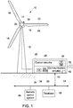
- FIG. 1 is a front view of a wind turbine system 10 configured to convert wind energy into electrical energy.
- the wind turbine system 10 includes a tower 12, a nacelle 14 and blades 16.
- the blades 16 are coupled to a generator 18 within the nacelle 14 by a hub 20 that rotates with the blades 16.
- the blades 16 are configured to convert the linear air flow from the wind into rotational motion. As the blades 16 rotate, the coupling between the hub 20 and the generator 18 within the nacelle 14 drives components of the generator 18 to rotate, thereby producing electrical energy. While three blades 16 are included in the wind turbine system 10 of the present embodiment, alternative embodiments may include more or fewer blades 16.
- Each blade 16 includes a leading edge 22 and a trailing edge 24.
- the air flow engages the leading edge 22 and flows toward the trailing edge 24. Due to the shape of the blades 16, aerodynamic forces caused by the air flow induce the blades 16 to rotate, thereby driving the generator 18 to produce electrical power.
- Efficiency of the wind turbine system 10 is at least partially dependent upon converting linear air flow into rotational energy. Therefore, the blades 16 are generally configured to efficiently transfer wind energy into rotational motion.
- blade shape may be selected to enhance air flow over the blade 16 such that aerodynamic forces induce the blade 16 to rotate.
- the blades 16 are typically manufactured to be substantially smooth, such that air flows over the blades 16 without interference.
- the wind turbine system 10 may also include a controller 26 to control the operation of the wind turbine system 10.
- the controller 26 may control the rotational speed (rpm) of the wind turbine system 10, the pitch of the blades 16, the yaw of the wind turbine system 10, as well as other parameters of operation.
- the controller 26 may include control circuitry 28, which may include a processor 30 and a memory component 32.
- the processor may be configured to analyze data, run programs, execute instructions, optimize operating parameters of the wind turbine system 10, and control the operating parameters of the wind turbine system 10.
- the memory component 32 may be any non-transitory computer readable medium.
- the memory component may store data, processor instructions, programs, optimization algorithms, lookup tables, models, and the like, including processor instructions for implementing the present approaches discussed herein.
- the controller 26 may include or communicate with an operator interface 34.
- the operator interface 34 may include a display 36 and/or operator inputs 38.
- the display may be an LCD, a cathode ray tube display, or some other kind of display.
- the display 36 may be an array of LEDs.
- the operator inputs 38 may include buttons, knobs, dials, and/or a keyboard and mouse.
- the display 36 and the operator inputs 38 may be combined into a single element (e.g., a touchscreen).
- the operator interface 38 allows the wind turbine system 10 to communicate with and control the operator and the operator to communicate with the wind turbine system 10.
- control circuitry 28, processor 30, memory 32, operator interface 34, display 36, operator inputs 38, communication circuitry 40, etc. may be situated in more than one unit and/or location.
- the controller 26 may also include communication circuitry 40.
- the communication circuitry may facilitate communication between the controller and an operator (e.g. via a smart device) by wired or wireless communication.
- the communication circuitry 40 may facilitate communication via a wireless or wired connection, through port 42, with a network 44.
- a remote control system 46 and/or a database 48 may be in communication with the controller 26 via the network 44.
- the remote control system 46 may provide an operator with control of one or more wind turbine systems spread across one or more locations.
- the network 44 may also provide access to one or more a databases 48.
- the databases 48 may provide the controller 26 with lookup tables, noise propagation models, weather models, weather data, local noise regulations, desired threshold noise levels, and the like.
- the disclosed techniques may include management of noise propagation by adjusting the rotational velocity of the wind turbine system 10, the blade 16 pitch, and the yaw of the wind turbine system.
- the rotational velocity of the wind turbine system 10 is the speed at which the blades 16 and the hub 20 rotate as a result of the blades' 16 interaction with the wind.
- FIG. 2A shows blade 16 pitch adjustment. Blade pitch adjustments are made by rotating the blade about the blade axis 60, which runs the length of the blade.
- FIG. 2B shows wind turbine yaw adjustment. A yaw adjustment is made by rotating the nacelle about the tower axis 62, which extends the height of the tower 12.
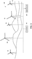
- FIG. 3 is a schematic diagram of a multitude of such wind turbine systems 10 disposed to function together as part of a wind power plant 80.
- Electrical currents produced by the wind turbine systems 10 of the wind power plant 80 are provided to an electrical power grid 82, thereby providing electrical energy to consumers connected to the grid 82.
- one or more controllers 26 may be provided to control and/or monitor operation of the wind power plant 80.
- Such controllers 26 may be provided as general or special purpose computers (or other suitable processor-based systems) configured to execute code or routines that allow monitoring and/or control of the wind power plant 80 as a whole and/or of individual wind turbine systems 10 of the plant 80.
- a controller 26 may execute control logic to optimize performance, noise generation, noise propagation, and/or any number of other factors, as discussed herein.
- the disclosed techniques may be used to control more than one wind turbine system 10 (e.g., wind power plant 80) in order to control the noise propagation attributable to the more than one wind turbine system 10 or wind power plant 80 at a given location.
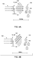
- FIG. 4A shows a wind turbine system 10, or wind power plant 80, that has not implemented the disclosed techniques for affecting sound propagation by misaligning the wake flow with the noise propagation in the direction of a noise sensitive site 104.
- air 100 flows toward the wind turbine system 10, or wind power plant 80, and interacts with the blades 16, causing the blades 16 to spin.
- the blades 16 moving through the air 100 may generate a wake flow 101 and noise 102, which propagate away from the wind turbine system 10.
- the sound 102 may propagate toward one or more noise sensitive sites 104, such as one or more nearby communities.
- the wake flow 100 and the noise propagation 102 are aligned in the direction of the noise sensitive site 104, the sound may propagate with the wake flow.
- noise sensitive sites 104 may represent any location or geographical area that may be sensitive to noise, including one or more residential, commercial, or industrial entities, or regions (e.g., housing, businesses, and so forth) as well as environmentally sensitive sites.
- a site 104 or entity may include a place where one or more people live, a school, an office, a park, a ranch, a farm, a wilderness preserve, etc.
- one or more acoustic receptors 106 may be disposed in or near the sensitive sites 104 in order to monitor noise levels in the site 104. Though FIG.
- the wind turbine system 10, or wind power plant 80 may be located near multiple sensitive sites 104.
- the present techniques may be used to control the wake flow 101 so as to control noise levels due to the wind turbine system 10 at multiple neighboring sites.
- FIG. 4A shows that the sensitive site 104 is located approximately 1500m away from the wind turbine system 10. It should be understood, however, that this distance is merely an example and intended to communicate that the disclosed techniques are concerned with far field sound propagation.
- far-field range is the distance from the wind turbine system 10 at which the environmental effects (e.g., wind, temperature, atmosphere) have a non-negligible effect on sound propagation. For near field range, environmental effects are negligible. Though there are many different ways to determine where far-field range begins, for the sake of simplicity, it is assumed that far-field range begins at approximately 450 to 500 meters from the nearest wind turbine system.
- FIG. 1 shows that the sensitive site 104 is located approximately 1500m away from the wind turbine system 10.
- FIG. 4B shows a wind turbine system 10, or wind power plant 80, that is implementing the disclosed wake management techniques to misalign the wake flow and the sound propagation 102 in the direction of the sensitive site 104.
- the controller 26 of the wind turbine system 10 may adjust one or more of the rotational velocity (rpm) of the wind turbine system 10, the yaw of the wind turbine system 10, or the pitch of the blades 16 in order to manage the wake effects and misalign the wake flow 101 and the sound propagation.
- Local regulations or the wishes of residents in the site 104 may require that noise levels in the site due to the wind turbine system 10 or wind power plant 80 stay below a threshold level. In the embodiment shown in FIG.
- noise reduced operation may be used to reduce the overall noise produced by the wind turbine system 10.
- NRO techniques typically include adjustment of the blade 16 pitch or the rotational velocity of the wind turbine system 10.
- NRO techniques may reduce the amount of power generated by the wind turbine system 10.
- the controller 26 may adjust the settings of the wind turbine system 10 to reduce noise levels at the site 104 as compared to the situation in FIG. 4A or generate more noise (and more power) than would be allowable in the situation shown in FIG. 4A , and still comply with local regulations.
- the disclosed techniques may allow the wind turbine system 10 to generate more power without an increase in the noise sensed by nearby sensitive sites 104.
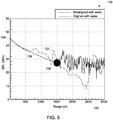
- FIG. 5 shows a sample plot 130 of the sound pressure level (SPL) in the direction of an acoustic receptor when the wake flow is aligned with sound propagation and when the wake flow is misaligned with sound propagation.
- the x-axis 132 represents the range, in meters, from the wind turbine system 10.
- the y-axis represents SPL in A-weighted decibels (dBA).
- Curve 136 shows the SPL when the wake flow and sound propagation are misaligned, as shown in FIG. 4B .
- Curve 137 shows the SPL when the wake flow and sound propagation are aligned, as shown in FIG. 4A .
- Curves 136 and 137 are the SPL in dBA at the given range from the wind turbine system 10, in the direction of interest (e.g., the direction from the wind turbine system 10 to the site 104 or acoustic receptors 106). Note that between 0 and 1500m, the SPL is generally lower when the wake flow and sound propagation are misaligned. Between about 1500m and 2500m, the SPL of curve 137 (wake flow and sound propagation aligned) is lower than the SPL of curve 136 (wake flow and sound propagation misaligned). Accordingly, in the specific example of FIG.
- a noise sensitive site 104 located between 1500m and 2500m from the wind turbine system 10 will likely experience lower noise levels when the wake flow and sound propagation are aligned.
- the distance at which this change occurs that is, the distance in the down wind direction at which the effect of an aligned wake flow on the noise levels at the site 104 changes relative to the misaligned condition, is called the turning point 138.
- the point of interest acoustic receptor 106 or site 104
- yaw adjustment or reduction of NRO modes may be useful in controlling the sound propagation.
- an increase of NRO modes may be useful to increase the power output of the wind turbine while still meeting noise regulations.
- FIG. 6 is a flow chart of a process 160 for maintaining the noise levels at a given location by controlling the wake effects of one or more wind turbine systems 10.
- lookup tables or models for the wake profiles and sound propagation are generated or updated. This may be done at any point before attempting to control the noise propagation of a given wind turbine system 10 (e.g., hours, days, weeks, months, or years before attempting to control the noise propagation of a given wind turbine system 10).
- the one or more lookup tables or models may be stored locally or remotely from a given wind turbine system, such as in the memory 32 of the controller 26, by the remote control system 46, or the database 48.
- the one or more lookup tables or models may be updated manually, remotely, or by software update.
- the one or more lookup tables or models are populated or updated that predict wake profiles based on given weather conditions.
- the weather conditions may include wind shear, wind speed, temperature, humidity, barometric pressure, any combination thereof, or other weather conditions.
- the lookup tables or models may be populated using data determined experimentally, by model, some mixture of the two, or some other way. For example, given the distance and direction of an acoustic receptor, as well as the local weather conditions, a lookup table or model may generate an estimation of the wake profiles for various weather conditions.
- the one or more lookup tables or models are populated or updated that predict sound propagation based on the given wake profiles. For example, given the wake profiles output from the lookup tables or models populated in block 162, the frequency, and the direction of the sensitive sites 104 or acoustic receptor 106 of interest, the lookup table may output an equation, table, or graph of the SPL versus distance, similar to the plot shown in FIG. 5 . In some embodiments, a single lookup table or model may be used to predict both wake profiles and sound propagation based upon weather data, effectively combining blocks 162 and 164 into a single block.
- the process 160 obtains current or predicted weather data, which may be indicative of one or more weather conditions surrounding the wind turbine system 10.
- the weather data may be accessed from the remote control system 46, from the database 48, or pulled from the internet via the network 44.
- the weather data may be updated periodically, and thus may be obtained by the process 160 once a minute, once every 5 minutes, once every 15 minutes, once every 30 minutes, once an hour, once every 2 hours, or 2, 4, 6, 8, or 10 times a day, or any time interval greater than, less than, or in between the listed intervals.
- the weather data may also be obtained upon receipt of a manual update instruction, such as when instructed by an operator.
- the process 160 may be configured to obtain weather data more frequently when the weather is subject to sudden changes (e.g., when a front is forecast to pass the wind turbine system 10).
- the weather data may include wind shear, wind speed, wind direction, temperature, humidity, barometric pressure, or any other weather data.
- the process 160 estimates the wake profiles of the air 100 after interacting with the blades 16 of the wind turbine system 10.
- the weather data obtained by the process 160 in block 166 is plugged into the one or more lookups table populated in block 162 using experimental data, models, or some other method.
- the weather data obtained by the process 160 in block 166 is fed into one or more models in order to estimate the wake profiles.
- the model or lookup table may be based solely on weather data.
- the model or lookup table may consider the rotational velocity (rpm) of the wind turbine system 10, the pitch of the blades, or other operational parameters of the wind turbine system 10. For example, given the distance and direction of an acoustic receptor, as well as the local weather conditions, the lookup table or model may generate an estimation of the wake profiles.
- the wake profiles derived in block 168 are used to estimate the sound propagation from the wind turbine system 10.
- the wake profiles and the sound propagation may be estimated using a single lookup table or model, effectively combining blocks 168 and 170.
- block 170 may produce a two or three dimensional map or prediction to determine how the sound of the wind turbine system propagates from the wind turbine system. In other embodiments, block 170 may only consider the sound propagation at one or more acoustic receptors 106, sensitive sites 104, or other points of interest.
- the lookup table may output an equation, table, or graph of the SPL versus distance, similar to the plot shown in FIG. 5 .
- the process 160 determines the noise turning point 138.
- the turning point 138 may be determined by examining the SPL in a given direction (e.g., the direction of the site 104 or acoustic receptors 106) at far-field distances from the wind turbine system 10, or by comparing noise levels when the wake flow and the sound propagation are aligned and misaligned.
- the turning point is the distance in the down wind direction at which the effect of the aligned wake flow on the noise levels at the site 104 changes relative to the misaligned wake flow.
- the process 160 determines the range at which the turning point 138 occurs.
- the process 160 determines whether the acoustic receptor 106 or site 104 of interest is inside of the turning point 138 range. That is, if the turning point 138 occurs at a known distance from the wind turbine system 10, is the acoustic receptor 106 or site 104 of interest inside of that distance or outside of that distance? If the acoustic receptor 106 or site 104 of interest is inside the turning point 138, the process 160 moves to block 176, wherein the process 160 directs the wake flow with yaw adjustments, and/or reduces NRO modes.
- the yaw adjustment may be in increments of 0.1 degrees, 0.5 degrees, 1 degrees, 2 degrees, 5 degrees, or 10 degrees, or any other increment.
- block 176 may include the act of the processor 30 generating or modifying a yaw signal, an rpm signal, or a blade pitch signal.
- the process 160 moves to block 178 and increases the Noise Reduced Operation (NRO) modes in order to increase the power of the wind turbine system while still maintaining noise levels at the acoustic receptor 106 or site 104 of interest below required levels.
- NRO modes may include adjustments to the rotational velocity (rpm) of the wind turbine system 10 and the pitch angle of the blades 16.
- block 178 may include the act of the processor 30 generating or modifying an rpm signal or a blade pitch signal.
- a wind turbine system 10 is located 1500 meters from a city with noise regulations requiring that the audible noise from the wind turbine system 10 at a given acoustic receptor 106 not exceed 30 dBA. Without making yaw adjustments, the operator of the turbine would likely adjust NRO modes, which would limit the noise (and likely the power) produced by the wind turbine system, without any ability to direct the wake flow and misalign the wake flow and the sound propagation, such that the acoustic receptor within the city measures less than 30 dBA.
- the operator may run the turbine to produce more noise (and likely more power), and then misalign the wake flow and noise propagation, such that the noise level at the relevant acoustic receptor 106 attributable to the wind turbine is below 30 dBA.
- a similar location 1500 meters away in the direction in which the wake flow and the sound propagation are aligned may experience a sound level of 60 dBA. Because there is no sound sensitivity at this location, it is not an issue for the wind turbine system 10 operator. Accordingly, the combination of making yaw adjustments and adjusting NRO modes, allows an operator to run one or more wind turbine systems 10 to produce more noise, and likely more power, than would otherwise be allowed, and then direct the noise away from the sensitive area.
- the process moves to decision 180 and estimates the noise levels at the one or more acoustic receptors 106 or sites 104 of interest. If the estimated noise levels are below the threshold levels, the process 160 operates the wind turbine system 10 according to the parameters determined in block 176 or 178 until new weather data is available or until it is time to obtain new weather data. In some embodiments, if the estimated noise levels are not below the threshold levels, the process 160 may optimize by returning to block 174. The process 160 may be configured to return to block 174 for reoptimization whenever reoptimization is needed, or when only small tweaks to the wind turbine system 10 are needed.
- the process 160 re-optimizes by returning to block 168 where the wake profiles are recalculated based on the new operating parameters determined in blocks 176 and 178. Some embodiments may be configured to re-optimize by returning to block 168 each time through the process 160. Other embodiments may return to block 168 when block 176 or block 178 results in substantial changes (e.g., above a threshold) to rotational velocity, blade pitch, or yaw. The process 160 may then proceed to recalculating the sound propagation (block 170), determining the noise turning point (block 172), and making adjustments to the wind turbine system (blocks 176 and 178).
- the process 160 then recalculates whether the estimated noise levels at the one or more acoustic receptors 106 or sites 104 of interest are below the threshold levels. If the estimated noise levels are not below the threshold levels, the process 160 may go through the optimization process again. If the estimated noise levels are below the threshold levels, the process 160 runs the wind turbine system 10 according to the parameters determined in blocks 176 and 178 until new weather data is available or until it is time to obtain new weather data.
- FIG. 6 shows an embodiment for steering the wake flow of a single wind turbine system relative to sound propagation in the direction of a single noise sensitive site 104 or acoustic receptor 106. It should be understood, however, that the same techniques may be used to control more than one wind turbine systems 10 (e.g., a wind power plant) and/or to steer wake flows to align or misalign the wake flow relative to sound propagation in the direction of multiple noise sensitive sites 104 or acoustic receptors 106.
- a wind turbine systems 10 e.g., a wind power plant
- the techniques described herein may be used to direct or steer the wake flows of one or more wind turbine systems to affect noise propagation in the direction of nearby communities or sites that are sensitive to noise.
- an operator of one or more wind turbine systems may operate the one or more wind turbine systems to generate more noise (and likely more power) than would otherwise be possible, and then reduce the noise at the community or noise sensitive site such that the noise attributable to the one or more wind turbine systems, as perceived from the community, does not increase.
Landscapes
- Engineering & Computer Science (AREA)
- Life Sciences & Earth Sciences (AREA)
- Sustainable Development (AREA)
- Sustainable Energy (AREA)
- Chemical & Material Sciences (AREA)
- Combustion & Propulsion (AREA)
- Mechanical Engineering (AREA)
- General Engineering & Computer Science (AREA)
- Power Engineering (AREA)
- Physics & Mathematics (AREA)
- Fluid Mechanics (AREA)
- Wind Motors (AREA)
Description
- The subject matter disclosed herein relates generally to wind turbines, and specifically to the propagation of noise created by wind turbines.
- Wind turbines typically include multiple blades extending from a central hub. The hub is rotatably coupled to a nacelle suspended above the ground by a tower. Generally, the nacelle houses an electric generator coupled to the hub and configured to generate electrical power as the blades are driven to rotate by the wind. Wind turbine blades are typically designed and manufactured to efficiently transfer wind energy into rotational motion, thereby providing the generator with sufficient rotational energy for power generation. See, for example,
EP 2 469 081 . - Wind power plants typically consist of multiple wind turbines of this type spread over a given geographic region. Wind passing over the region causes blades associated with each wind turbine to rotate, thereby generating electrical power. Noise generated by a wind turbine, or a group of wind turbines, may propagate long distances, in some cases a few kilometers. Sound propagation may be influenced by environmental conditions such as wind, temperature, atmospheric turbulence, terrain, etc. Because of local regulations, the presence of nearby residents, or other factors, an operator may desire to operate one or more wind turbines such that the noise level at one or more acoustic receptors remains below a specified noise level.
- Certain embodiments commensurate in scope with the original claims are summarized below. These embodiments are not intended to limit the scope of the claims, but rather these embodiments are intended only to provide a brief summary of possible forms of the claims. Indeed, the claims may encompass a variety of forms that may be similar to or different from the embodiments set forth below.
- The present invention is defined by the appended claims.
- Various features, aspects, and advantages of the present invention will become better understood when the following detailed description is read with reference to the accompanying drawings in which like characters represent like parts throughout the drawings, wherein:
-
FIG. 1 shows a wind turbine system configured to convert wind energy into electrical energy in accordance with aspects of the present disclosure; -
FIG. 2A shows pitch adjustment of a turbine blade in accordance with aspects of the present disclosure; -
FIG. 2B shows yaw adjustment of a wind turbine system in accordance with aspects of the present disclosure; -
FIG. 3 shows a wind power plant having a plurality of the wind turbine systems shown inFIG. 1 in accordance with aspects of the present disclosure; -
FIG. 4A shows a wind turbine system that is not using the disclosed techniques to direct the wake flow in accordance with aspects of the present disclosure; -
FIG. 4B shows a wind turbine system that uses the disclosed techniques to direct the wake flow in accordance with aspects of the present disclosure; -
FIG. 5 is a sample plot of sound pressure level in the direction of an acoustic receptor plotted against range when the wake flow and the sound propagation are aligned and misaligned in accordance with aspects of the present disclosure; and -
FIG. 6 is a flow chart for a process for maintaining noise levels at a given location by controlling the wake effects in accordance with aspects of the present disclosure. - One or more specific embodiments will be described below. In an effort to provide a concise description of these embodiments, all features of an actual implementation may not be described in the specification. It should be appreciated that in the development of any such actual implementation, as in any engineering or design project, numerous implementation-specific decisions must be made to achieve the developers' specific goals, such as compliance with system-related and business-related constraints, which may vary from one implementation to another. Moreover, it should be appreciated that such a development effort might be complex and time consuming, but would nevertheless be a routine undertaking of design, fabrication, and manufacture for those of ordinary skill having the benefit of this disclosure.
- When introducing elements of various embodiments of the present invention, the articles "a," "an," "the," and "said" are intended to mean that there are one or more of the elements. The terms "comprising," "including," and "having" are intended to be inclusive and mean that there may be additional elements other than the listed elements. Furthermore, any numerical examples in the following discussion are intended to be non-limiting, and thus additional numerical values, ranges, and percentages are within the scope of the disclosed embodiments.
- Some wind turbine systems or wind power plants may be located near communities or other sites that are sensitive to noise. Due to local regulations, or the requests of nearby land owners, the operator of one or more wind turbine systems may desire to operate the wind turbine systems so as to keep the noise level at one or more far-field acoustic receptors attributable to the wind turbine systems below a threshold level. Operating a wind turbine system so as to reduce the amount of noise generated may result in a reduced amount of power produced.
- The way sound propagates from a wind turbine may be affected by environmental conditions such as wind, temperature, atmospheric turbulence, terrain, etc. Additionally, wind turbines generate wake flows in the downwind direction as the turbine blades rotate and interact with the passing air flow. The wind turbine wake flow may also influence the sound propagation by changing the speed of sound propagation. Specifically, the wind turbine wake flow may affect the vertical wind profile, which in turn affects the speed at which sound travels. Generally, when the wake flow and noise propagation are aligned, noise levels increase. When wake flow and noise propagation are misaligned, noise levels decrease. It should be understood, however, that these are general trends (which will be addressed in more detail with regard to
FIG. 5 ) and that there may be specific distances in specific directions at which this trend is reversed. Accordingly, the wake flow may influence the speed at which sound propagates from the wind turbine in a given direction. Because the wake flow varies as one moves away from the wind turbine, the effect of the wake flow on sound propagation also changes with the distance from the wind turbine. The techniques described herein may be used to control the wake effects of a wind turbine system, giving the operator the ability to affect noise propagation from the wind turbine system in a given direction. - By making yaw adjustments to a wind turbine, an operator can "steer" the wake flow to affect noise propagation. Such yaw adjustments may increase or decrease noise levels attributable to the wind turbine at a given noise sensitive site, depending upon its distance and direction from the wind turbine. If the operator makes yaw adjustments that direct the wake flow away from the noise sensitive site, then sound propagation through the wake flow in the direction of the noise sensitive site may be reduced. The operator may then operate the one or more wind turbine systems so that they produce more power than would otherwise be allowed, resulting in noise levels at the nearby community or noise sensitive site that are either the same or lower than they would otherwise be in similar power generation systems without the benefit of the present approaches.
-
FIG. 1 is a front view of awind turbine system 10 configured to convert wind energy into electrical energy. Thewind turbine system 10 includes atower 12, anacelle 14 andblades 16. Theblades 16 are coupled to agenerator 18 within thenacelle 14 by ahub 20 that rotates with theblades 16. Theblades 16 are configured to convert the linear air flow from the wind into rotational motion. As theblades 16 rotate, the coupling between thehub 20 and thegenerator 18 within thenacelle 14 drives components of thegenerator 18 to rotate, thereby producing electrical energy. While threeblades 16 are included in thewind turbine system 10 of the present embodiment, alternative embodiments may include more orfewer blades 16. - Each
blade 16 includes a leadingedge 22 and atrailing edge 24. The air flow engages the leadingedge 22 and flows toward thetrailing edge 24. Due to the shape of theblades 16, aerodynamic forces caused by the air flow induce theblades 16 to rotate, thereby driving thegenerator 18 to produce electrical power. Efficiency of thewind turbine system 10 is at least partially dependent upon converting linear air flow into rotational energy. Therefore, theblades 16 are generally configured to efficiently transfer wind energy into rotational motion. For example, blade shape may be selected to enhance air flow over theblade 16 such that aerodynamic forces induce theblade 16 to rotate. In addition, theblades 16 are typically manufactured to be substantially smooth, such that air flows over theblades 16 without interference. - The
wind turbine system 10 may also include acontroller 26 to control the operation of thewind turbine system 10. For example, thecontroller 26 may control the rotational speed (rpm) of thewind turbine system 10, the pitch of theblades 16, the yaw of thewind turbine system 10, as well as other parameters of operation. Thecontroller 26 may includecontrol circuitry 28, which may include aprocessor 30 and amemory component 32. The processor may be configured to analyze data, run programs, execute instructions, optimize operating parameters of thewind turbine system 10, and control the operating parameters of thewind turbine system 10. Thememory component 32 may be any non-transitory computer readable medium. The memory component may store data, processor instructions, programs, optimization algorithms, lookup tables, models, and the like, including processor instructions for implementing the present approaches discussed herein. - The
controller 26 may include or communicate with anoperator interface 34. Theoperator interface 34 may include adisplay 36 and/oroperator inputs 38. The display may be an LCD, a cathode ray tube display, or some other kind of display. In some embodiments, thedisplay 36 may be an array of LEDs. Theoperator inputs 38 may include buttons, knobs, dials, and/or a keyboard and mouse. In some embodiments, thedisplay 36 and theoperator inputs 38 may be combined into a single element (e.g., a touchscreen). Theoperator interface 38 allows thewind turbine system 10 to communicate with and control the operator and the operator to communicate with thewind turbine system 10. Though the various components of thecontroller 26 are shown within a common unit or housing for purposes of illustration, in some embodiments the various components (e.g.,control circuitry 28,processor 30,memory 32,operator interface 34,display 36,operator inputs 38,communication circuitry 40, etc.) maybe situated in more than one unit and/or location. - The
controller 26 may also includecommunication circuitry 40. In some embodiments, the communication circuitry may facilitate communication between the controller and an operator (e.g. via a smart device) by wired or wireless communication. In some embodiments, thecommunication circuitry 40 may facilitate communication via a wireless or wired connection, throughport 42, with anetwork 44. In some embodiments, aremote control system 46 and/or adatabase 48 may be in communication with thecontroller 26 via thenetwork 44. Theremote control system 46 may provide an operator with control of one or more wind turbine systems spread across one or more locations. Thenetwork 44 may also provide access to one or more adatabases 48. Thedatabases 48 may provide thecontroller 26 with lookup tables, noise propagation models, weather models, weather data, local noise regulations, desired threshold noise levels, and the like. - The disclosed techniques may include management of noise propagation by adjusting the rotational velocity of the
wind turbine system 10, theblade 16 pitch, and the yaw of the wind turbine system. The rotational velocity of thewind turbine system 10 is the speed at which theblades 16 and thehub 20 rotate as a result of the blades' 16 interaction with the wind.FIG. 2A showsblade 16 pitch adjustment. Blade pitch adjustments are made by rotating the blade about theblade axis 60, which runs the length of the blade.FIG. 2B shows wind turbine yaw adjustment. A yaw adjustment is made by rotating the nacelle about thetower axis 62, which extends the height of thetower 12. - With the foregoing discussion of a
wind turbine system 10 in mind,FIG. 3 is a schematic diagram of a multitude of suchwind turbine systems 10 disposed to function together as part of awind power plant 80. Electrical currents produced by thewind turbine systems 10 of thewind power plant 80 are provided to anelectrical power grid 82, thereby providing electrical energy to consumers connected to thegrid 82. Further, one ormore controllers 26 may be provided to control and/or monitor operation of thewind power plant 80.Such controllers 26 may be provided as general or special purpose computers (or other suitable processor-based systems) configured to execute code or routines that allow monitoring and/or control of thewind power plant 80 as a whole and/or of individualwind turbine systems 10 of theplant 80. For example, in one embodiment, a controller 26 (or other processor based system) may execute control logic to optimize performance, noise generation, noise propagation, and/or any number of other factors, as discussed herein. The disclosed techniques may be used to control more than one wind turbine system 10 (e.g., wind power plant 80) in order to control the noise propagation attributable to the more than onewind turbine system 10 orwind power plant 80 at a given location. -
FIG. 4A shows awind turbine system 10, orwind power plant 80, that has not implemented the disclosed techniques for affecting sound propagation by misaligning the wake flow with the noise propagation in the direction of a noisesensitive site 104. InFIG. 4A ,air 100 flows toward thewind turbine system 10, orwind power plant 80, and interacts with theblades 16, causing theblades 16 to spin. Theblades 16 moving through theair 100 may generate awake flow 101 andnoise 102, which propagate away from thewind turbine system 10. In some embodiments, thesound 102 may propagate toward one or more noisesensitive sites 104, such as one or more nearby communities. When thewake flow 100 and thenoise propagation 102 are aligned in the direction of the noisesensitive site 104, the sound may propagate with the wake flow. It should be understood that such noisesensitive sites 104 may represent any location or geographical area that may be sensitive to noise, including one or more residential, commercial, or industrial entities, or regions (e.g., housing, businesses, and so forth) as well as environmentally sensitive sites. For example, such asite 104 or entity may include a place where one or more people live, a school, an office, a park, a ranch, a farm, a wilderness preserve, etc. In some embodiments, one or moreacoustic receptors 106 may be disposed in or near thesensitive sites 104 in order to monitor noise levels in thesite 104. ThoughFIG. 4A shows asingle site 104 in the form of housing, it should be understood that in some embodiments, thewind turbine system 10, orwind power plant 80, may be located near multiplesensitive sites 104. As such, the present techniques may be used to control thewake flow 101 so as to control noise levels due to thewind turbine system 10 at multiple neighboring sites. -
FIG. 4A shows that thesensitive site 104 is located approximately 1500m away from thewind turbine system 10. It should be understood, however, that this distance is merely an example and intended to communicate that the disclosed techniques are concerned with far field sound propagation. In general, far-field range is the distance from thewind turbine system 10 at which the environmental effects (e.g., wind, temperature, atmosphere) have a non-negligible effect on sound propagation. For near field range, environmental effects are negligible. Though there are many different ways to determine where far-field range begins, for the sake of simplicity, it is assumed that far-field range begins at approximately 450 to 500 meters from the nearest wind turbine system.FIG. 4B shows awind turbine system 10, orwind power plant 80, that is implementing the disclosed wake management techniques to misalign the wake flow and thesound propagation 102 in the direction of thesensitive site 104. As will be described in more detail later, thecontroller 26 of thewind turbine system 10 may adjust one or more of the rotational velocity (rpm) of thewind turbine system 10, the yaw of thewind turbine system 10, or the pitch of theblades 16 in order to manage the wake effects and misalign thewake flow 101 and the sound propagation. Local regulations or the wishes of residents in thesite 104 may require that noise levels in the site due to thewind turbine system 10 orwind power plant 80 stay below a threshold level. In the embodiment shown inFIG. 4A , in which thewake flow 101 and thenoise propagation 102 are aligned in the direction of thesite 104, noise reduced operation (NRO) may be used to reduce the overall noise produced by thewind turbine system 10. NRO techniques typically include adjustment of theblade 16 pitch or the rotational velocity of thewind turbine system 10. NRO techniques may reduce the amount of power generated by thewind turbine system 10. - By adjusting the yaw of the
wind turbine system 10, in addition to the rotational speed and the blade pitch, to misalign thenoise propagation 102 and thewake flow 101 in the direction of thesite 104, as shown inFIG. 4B , thecontroller 26 may adjust the settings of thewind turbine system 10 to reduce noise levels at thesite 104 as compared to the situation inFIG. 4A or generate more noise (and more power) than would be allowable in the situation shown inFIG. 4A , and still comply with local regulations. Thecontroller 26 in the example shown inFIG. 4B may then steer thewake flow 101 such that it is misaligned with thenoise propagation 102 in the direction of the noisesensitive site 104, resulting in the noise level sensed at theacoustic receptor 106 being the same or less than the noise sensed in the example shown inFIG. 4A . As such, the disclosed techniques may allow thewind turbine system 10 to generate more power without an increase in the noise sensed by nearbysensitive sites 104. -
FIG. 5 shows asample plot 130 of the sound pressure level (SPL) in the direction of an acoustic receptor when the wake flow is aligned with sound propagation and when the wake flow is misaligned with sound propagation. Thex-axis 132 represents the range, in meters, from thewind turbine system 10. The y-axis represents SPL in A-weighted decibels (dBA).Curve 136 shows the SPL when the wake flow and sound propagation are misaligned, as shown inFIG. 4B .Curve 137 shows the SPL when the wake flow and sound propagation are aligned, as shown inFIG. 4A .Curves wind turbine system 10, in the direction of interest (e.g., the direction from thewind turbine system 10 to thesite 104 or acoustic receptors 106). Note that between 0 and 1500m, the SPL is generally lower when the wake flow and sound propagation are misaligned. Between about 1500m and 2500m, the SPL of curve 137 (wake flow and sound propagation aligned) is lower than the SPL of curve 136 (wake flow and sound propagation misaligned). Accordingly, in the specific example ofFIG. 5 , a noisesensitive site 104 located between 1500m and 2500m from thewind turbine system 10 will likely experience lower noise levels when the wake flow and sound propagation are aligned. The distance at which this change occurs, that is, the distance in the down wind direction at which the effect of an aligned wake flow on the noise levels at thesite 104 changes relative to the misaligned condition, is called theturning point 138. If the point of interest (acoustic receptor 106 or site 104) is before the turning point, yaw adjustment or reduction of NRO modes may be useful in controlling the sound propagation. If the point of interest (acoustic receptor 106 or noise sensitive site 104) is after the turning point, an increase of NRO modes may be useful to increase the power output of the wind turbine while still meeting noise regulations. -
FIG. 6 is a flow chart of aprocess 160 for maintaining the noise levels at a given location by controlling the wake effects of one or morewind turbine systems 10. At some point prior to implementing the disclosed techniques, lookup tables or models for the wake profiles and sound propagation are generated or updated. This may be done at any point before attempting to control the noise propagation of a given wind turbine system 10 (e.g., hours, days, weeks, months, or years before attempting to control the noise propagation of a given wind turbine system 10). The one or more lookup tables or models may be stored locally or remotely from a given wind turbine system, such as in thememory 32 of thecontroller 26, by theremote control system 46, or thedatabase 48. The one or more lookup tables or models may be updated manually, remotely, or by software update. - In
block 162, the one or more lookup tables or models are populated or updated that predict wake profiles based on given weather conditions. In some embodiments, the weather conditions may include wind shear, wind speed, temperature, humidity, barometric pressure, any combination thereof, or other weather conditions. The lookup tables or models may be populated using data determined experimentally, by model, some mixture of the two, or some other way. For example, given the distance and direction of an acoustic receptor, as well as the local weather conditions, a lookup table or model may generate an estimation of the wake profiles for various weather conditions. - In
block 164, the one or more lookup tables or models are populated or updated that predict sound propagation based on the given wake profiles. For example, given the wake profiles output from the lookup tables or models populated inblock 162, the frequency, and the direction of thesensitive sites 104 oracoustic receptor 106 of interest, the lookup table may output an equation, table, or graph of the SPL versus distance, similar to the plot shown inFIG. 5 . In some embodiments, a single lookup table or model may be used to predict both wake profiles and sound propagation based upon weather data, effectively combiningblocks - In
block 166, theprocess 160 obtains current or predicted weather data, which may be indicative of one or more weather conditions surrounding thewind turbine system 10. The weather data may be accessed from theremote control system 46, from thedatabase 48, or pulled from the internet via thenetwork 44. The weather data may be updated periodically, and thus may be obtained by theprocess 160 once a minute, once every 5 minutes, once every 15 minutes, once every 30 minutes, once an hour, once every 2 hours, or 2, 4, 6, 8, or 10 times a day, or any time interval greater than, less than, or in between the listed intervals. Alternatively, the weather data may also be obtained upon receipt of a manual update instruction, such as when instructed by an operator. In some embodiments, theprocess 160 may be configured to obtain weather data more frequently when the weather is subject to sudden changes (e.g., when a front is forecast to pass the wind turbine system 10). The weather data may include wind shear, wind speed, wind direction, temperature, humidity, barometric pressure, or any other weather data. - In
block 168 theprocess 160 estimates the wake profiles of theair 100 after interacting with theblades 16 of thewind turbine system 10. In some embodiments, the weather data obtained by theprocess 160 inblock 166 is plugged into the one or more lookups table populated inblock 162 using experimental data, models, or some other method. In other embodiments, the weather data obtained by theprocess 160 inblock 166 is fed into one or more models in order to estimate the wake profiles. In some embodiments, the model or lookup table may be based solely on weather data. In other embodiments, the model or lookup table may consider the rotational velocity (rpm) of thewind turbine system 10, the pitch of the blades, or other operational parameters of thewind turbine system 10. For example, given the distance and direction of an acoustic receptor, as well as the local weather conditions, the lookup table or model may generate an estimation of the wake profiles. - In
block 170, the wake profiles derived inblock 168 are used to estimate the sound propagation from thewind turbine system 10. As previously mentioned, in some embodiments, the wake profiles and the sound propagation may be estimated using a single lookup table or model, effectively combiningblocks acoustic receptors 106,sensitive sites 104, or other points of interest. For example, given the wake profiles output from the lookup tables or models populated inblock 162, as well as the direction of thesite 104 oracoustic receptor 106 of interest, the lookup table may output an equation, table, or graph of the SPL versus distance, similar to the plot shown inFIG. 5 . - In
block 172, theprocess 160 determines thenoise turning point 138. As was discussed with regard toFIG. 5 , theturning point 138 may be determined by examining the SPL in a given direction (e.g., the direction of thesite 104 or acoustic receptors 106) at far-field distances from thewind turbine system 10, or by comparing noise levels when the wake flow and the sound propagation are aligned and misaligned. As can be seen inFIG. 5 , the turning point is the distance in the down wind direction at which the effect of the aligned wake flow on the noise levels at thesite 104 changes relative to the misaligned wake flow. Inblock 172, theprocess 160 determines the range at which theturning point 138 occurs. - At
decision 174, theprocess 160 determines whether theacoustic receptor 106 orsite 104 of interest is inside of theturning point 138 range. That is, if theturning point 138 occurs at a known distance from thewind turbine system 10, is theacoustic receptor 106 orsite 104 of interest inside of that distance or outside of that distance? If theacoustic receptor 106 orsite 104 of interest is inside theturning point 138, theprocess 160 moves to block 176, wherein theprocess 160 directs the wake flow with yaw adjustments, and/or reduces NRO modes. In some embodiments, the yaw adjustment may be in increments of 0.1 degrees, 0.5 degrees, 1 degrees, 2 degrees, 5 degrees, or 10 degrees, or any other increment. By making yaw adjustments to thewind turbine system 10, theprocess 160 may adjust the angle at which thewind 100 hits theblades 16, which in turn affects the wake profiles. Thus, by making yaw adjustments to thewind turbine system 10, theprocess 160 or thecontroller 26 may misalign the wake flow and the noise propagation in the direction of thesite 104 or acoustic receptor of interest, which may reduce the noise level. In some embodiments, block 176 may include the act of theprocessor 30 generating or modifying a yaw signal, an rpm signal, or a blade pitch signal. - If, on the other hand, the
acoustic receptor 106 orsite 104 of interest is outside of theturning point 138 distance, theprocess 160 moves to block 178 and increases the Noise Reduced Operation (NRO) modes in order to increase the power of the wind turbine system while still maintaining noise levels at theacoustic receptor 106 orsite 104 of interest below required levels. Increasing NRO modes may include adjustments to the rotational velocity (rpm) of thewind turbine system 10 and the pitch angle of theblades 16. In some embodiments, block 178 may include the act of theprocessor 30 generating or modifying an rpm signal or a blade pitch signal. - For example, assume a
wind turbine system 10 is located 1500 meters from a city with noise regulations requiring that the audible noise from thewind turbine system 10 at a givenacoustic receptor 106 not exceed 30 dBA. Without making yaw adjustments, the operator of the turbine would likely adjust NRO modes, which would limit the noise (and likely the power) produced by the wind turbine system, without any ability to direct the wake flow and misalign the wake flow and the sound propagation, such that the acoustic receptor within the city measures less than 30 dBA. However, by using yaw adjustments to steer the wake flow, the operator may run the turbine to produce more noise (and likely more power), and then misalign the wake flow and noise propagation, such that the noise level at the relevantacoustic receptor 106 attributable to the wind turbine is below 30 dBA. In such an embodiment, for example, asimilar location 1500 meters away in the direction in which the wake flow and the sound propagation are aligned, may experience a sound level of 60 dBA. Because there is no sound sensitivity at this location, it is not an issue for thewind turbine system 10 operator. Accordingly, the combination of making yaw adjustments and adjusting NRO modes, allows an operator to run one or morewind turbine systems 10 to produce more noise, and likely more power, than would otherwise be allowed, and then direct the noise away from the sensitive area. - Whether the
acoustic receptor 106 orsite 104 of interest is located before or after theturning point 138, the process moves todecision 180 and estimates the noise levels at the one or moreacoustic receptors 106 orsites 104 of interest. If the estimated noise levels are below the threshold levels, theprocess 160 operates thewind turbine system 10 according to the parameters determined inblock process 160 may optimize by returning to block 174. Theprocess 160 may be configured to return to block 174 for reoptimization whenever reoptimization is needed, or when only small tweaks to thewind turbine system 10 are needed. - In some embodiments, if the estimated noise levels are above the threshold levels, the
process 160 re-optimizes by returning to block 168 where the wake profiles are recalculated based on the new operating parameters determined inblocks process 160. Other embodiments may return to block 168 when block 176 or block 178 results in substantial changes (e.g., above a threshold) to rotational velocity, blade pitch, or yaw. Theprocess 160 may then proceed to recalculating the sound propagation (block 170), determining the noise turning point (block 172), and making adjustments to the wind turbine system (blocks 176 and 178). Theprocess 160 then recalculates whether the estimated noise levels at the one or moreacoustic receptors 106 orsites 104 of interest are below the threshold levels. If the estimated noise levels are not below the threshold levels, theprocess 160 may go through the optimization process again. If the estimated noise levels are below the threshold levels, theprocess 160 runs thewind turbine system 10 according to the parameters determined inblocks - For clarity,
FIG. 6 shows an embodiment for steering the wake flow of a single wind turbine system relative to sound propagation in the direction of a single noisesensitive site 104 oracoustic receptor 106. It should be understood, however, that the same techniques may be used to control more than one wind turbine systems 10 (e.g., a wind power plant) and/or to steer wake flows to align or misalign the wake flow relative to sound propagation in the direction of multiple noisesensitive sites 104 oracoustic receptors 106. - The techniques described herein may be used to direct or steer the wake flows of one or more wind turbine systems to affect noise propagation in the direction of nearby communities or sites that are sensitive to noise. Using these techniques, an operator of one or more wind turbine systems may operate the one or more wind turbine systems to generate more noise (and likely more power) than would otherwise be possible, and then reduce the noise at the community or noise sensitive site such that the noise attributable to the one or more wind turbine systems, as perceived from the community, does not increase.
- This written description uses examples to disclose the invention, including the preferred mode, and also to enable any person skilled in the art to practice the invention, including making and using any devices or systems and performing any incorporated methods. The patentable scope of the invention is defined by the claims.
Claims (17)
- A method (160) of controlling a wind turbine (10) comprising:obtaining (166) weather data indicative of one or more weather conditions at the wind turbine (10);estimating (168) wake profiles based on the obtained weather data;estimating (170) sound propagation in a direction of an acoustic receptor (106) based on the estimated wake profiles;identifying (172) a turning point (138) in the estimated sound propagation, wherein the turning point (138) is a distance in the direction of the acoustic receptor (106) at which a noise level becomes lower when the wake profiles are aligned with the sound propagation than when the wake profiles are misaligned with the sound propagation;optimizing the operation of the wind turbine (10) comprising:adjusting (182) a yaw signal if the acoustic receptor (106) is before the turning point (138), wherein the yaw signal controls the yaw of a nacelle (14) relative to a tower (12); andincreasing a noise reduced operation (NRO) mode if the acoustic receptor (106) is after the turning point (138);estimating the noise level at the acoustic receptor (106); andre-optimizing the operation of the wind turbine (10) if the estimated noise level at the acoustic receptor (106) exceeds a threshold noise level.
- The method (160) of claim 1, wherein estimating (168) wake profiles is done using a first lookup table, and estimating (170) sound propagation is done using a second lookup table.
- The method (160) of any preceding claim, further comprising:generating a blade pitch signal, wherein the blade pitch signal controls the pitch of a plurality of blades (16) of the wind turbine (10);generating an rpm signal, wherein the rpm signal controls a rotational velocity of the plurality of blades (16) about a hub (20); andadjusting one or both of the blade pitch signal and the rpm signal if the estimated noise level at the noise sensitive site exceeds the threshold noise level.
- The method (160) of any preceding claim, wherein the weather data comprises wind shear.
- The method (160) of any preceding claim, comprising:reducing a noise reduced operation (NRO) mode if the noise sensitive site is before the turning point (138); andincreasing the NRO mode if the noise sensitive site is after the turning point (138).
- The method (160) of any preceding claim, wherein the noise sensitive site comprises one or more acoustic receptors (106) configured to sense the noise level at the noise sensitive site.
- The method (160) of any preceding claim, wherein optimizing the operation of the wind turbine (10) comprises one or both of:adjusting a blade pitch signal, wherein the blade pitch signal controls the pitch of a plurality of blade of the wind turbine (10); andadjusting an rpm signal, wherein the rpm signal controls a rotational velocity of the plurality of blades about a hub.
- The method (160) of any preceding claim, wherein optimizing the operation of the wind turbine (10) comprises reducing the NRO mode if the acoustic receptor is before the turning point and increasing the NRO mode if the acoustic receptor is after the turning point.
- The method (160) of any preceding claim, wherein the weather data comprises temperature profile.
- The method (160) of any preceding claim, wherein adjusting the yaw signal is configured to direct the wake flow away from the acoustic receptor.
- A control system (26) for a wind turbine (10) comprising:communication circuitry (40), communicatively coupled to a network (44), configured to obtain weather data indicative of one or more weather conditions at the wind turbine(10); anda processor (30) configured to implement the method (160) according to any preceding claim.
- The control system (26) of claim 11, wherein the processor (30) is configured to:generate a blade pitch signal, wherein the blade pitch signal controls the pitch of a plurality of blades (16) of the wind turbine (10);generate an rpm signal, wherein the rpm signal controls a rotational velocity of the plurality of blades about a hub (20); andmodify one or both of the blade pitch signal or the rpm signal if the noise level at the acoustic receptor (106) exceeds the threshold noise level;
- The control system (26) of claim 11 or claim 12, wherein the processor (30) is configured to:identify the turning point (138) in the estimated far-field sound propagation; andincrease a noise reduced operation (NRO) mode if the acoustic receptor (106) is after the turning point.
- The control system (26) of any of claims 11 to 13, wherein estimating wake profiles and far field sound propagation includes use of one or more lookup tables.
- The control system (26) of any of claims 11 to 14, wherein the acoustic receptor (106) is disposed in or near a community.
- The control system (26) of any of claims 11 to 15, wherein the threshold noise level is determined by one or more regulations of the community.
- The control system (26) of any of claims 11 to 16, wherein modifying the yaw adjustment signal is configured to direct the wake flow away from the acoustic receptor (106).
Applications Claiming Priority (1)
| Application Number | Priority Date | Filing Date | Title |
|---|---|---|---|
| US14/718,833 US10024304B2 (en) | 2015-05-21 | 2015-05-21 | System and methods for controlling noise propagation of wind turbines |
Publications (2)
| Publication Number | Publication Date |
|---|---|
| EP3096006A1 EP3096006A1 (en) | 2016-11-23 |
| EP3096006B1 true EP3096006B1 (en) | 2019-10-02 |
Family
ID=56068704
Family Applications (1)
| Application Number | Title | Priority Date | Filing Date |
|---|---|---|---|
| EP16170167.7A Active EP3096006B1 (en) | 2015-05-21 | 2016-05-18 | System and methods for controlling noise propagation of wind turbines |
Country Status (5)
| Country | Link |
|---|---|
| US (1) | US10024304B2 (en) |
| EP (1) | EP3096006B1 (en) |
| CA (1) | CA2930475C (en) |
| DK (1) | DK3096006T3 (en) |
| ES (1) | ES2763383T3 (en) |
Families Citing this family (20)
| Publication number | Priority date | Publication date | Assignee | Title |
|---|---|---|---|---|
| US10823643B2 (en) * | 2015-11-06 | 2020-11-03 | Aktiebolaget Skf | Method and device for handling dynamic characteristics of a vibrating machine component |
| US10247171B2 (en) * | 2016-06-14 | 2019-04-02 | General Electric Company | System and method for coordinating wake and noise control systems of a wind farm |
| EP3551879B1 (en) * | 2016-12-09 | 2020-10-28 | Vestas Wind Systems A/S | Adaptive noise control for wind turbine |
| FR3065804B1 (en) * | 2017-04-28 | 2019-06-21 | Soletanche Freyssinet | METHOD FOR EVALUATING THE ACOUSTIC IMPACT OF A VIRTUAL WIND FARM |
| US10451039B2 (en) | 2017-06-09 | 2019-10-22 | General Electric Company | System and method for reducing wind turbine noise during high wind speed conditions |
| CN107956638B (en) * | 2017-11-15 | 2019-08-16 | 三一重能有限公司 | Blower group of planes control method, control system and wind field |
| CN108691730B (en) * | 2018-05-09 | 2020-02-21 | 许继集团有限公司 | Wind driven generator system, wind energy data error correction method and yaw control method |
| CN110500233B (en) * | 2018-05-18 | 2020-07-07 | 北京金风科创风电设备有限公司 | Method and device for noise control of a plurality of wind energy installations |
| CN110500234B (en) * | 2018-05-18 | 2020-07-03 | 北京金风科创风电设备有限公司 | Method and device for noise control of wind generating set |
| CN109026530B (en) * | 2018-07-20 | 2019-10-11 | 国网冀北电力有限公司迁西县供电分公司 | A kind of wind power generating set intelligence learning method |
| EP3696406A1 (en) * | 2019-02-13 | 2020-08-19 | Siemens Gamesa Renewable Energy A/S | A method for computer-implemented analysis of a wind farm comprising a number of wind turbines |
| GB2584111A (en) * | 2019-05-21 | 2020-11-25 | Renewal Energy Systems Ltd | System and method for controlling the noise emission of one or more wind turbines |
| CN114026323B (en) | 2019-06-24 | 2023-09-15 | 维斯塔斯风力系统有限公司 | Method of controlling noise emissions from individual blades of a wind turbine |
| CN110397553B (en) * | 2019-07-26 | 2020-09-25 | 山东中车风电有限公司 | Model-free wind power plant wake flow management method and system |
| CN116157598A (en) | 2020-07-13 | 2023-05-23 | 文德斯科有限公司 | Method and system for advanced yaw control of a wind turbine |
| CN111980857A (en) * | 2020-08-26 | 2020-11-24 | 上海电气风电集团股份有限公司 | Closed-loop control method and device for wind power plant and computer readable storage medium |
| WO2022148513A1 (en) * | 2021-01-05 | 2022-07-14 | Vestas Wind Systems A/S | Masking tonal noise from a wind turbine |
| EP4365438A1 (en) * | 2022-11-02 | 2024-05-08 | Vestas Wind Systems A/S | Control of a wind turbine based on predicting amplitude modulation (am) noise |
| EP4431726A1 (en) * | 2023-03-17 | 2024-09-18 | Siemens Gamesa Renewable Energy A/S | Evaluation of noise emission for a wind park environment |
| CN118242233B (en) * | 2024-05-28 | 2024-09-17 | 江苏海立普电力科技有限公司 | Multidimensional monitoring system for wind power generation and monitoring method thereof |
Family Cites Families (70)
| Publication number | Priority date | Publication date | Assignee | Title |
|---|---|---|---|---|
| US6004095A (en) | 1996-06-10 | 1999-12-21 | Massachusetts Institute Of Technology | Reduction of turbomachinery noise |
| CA2522280A1 (en) | 2003-04-17 | 2004-10-28 | New World Generation Inc. | Wind turbine with friction drive power take off on outer rim |
| US20070031237A1 (en) | 2005-07-29 | 2007-02-08 | General Electric Company | Method and apparatus for producing wind energy with reduced wind turbine noise |
| WO2007048001A2 (en) | 2005-10-20 | 2007-04-26 | Reidy Michael T | Wind energy harnessing apparatuses, systems, methods, and improvements |
| US20070124025A1 (en) | 2005-11-29 | 2007-05-31 | General Electric Company | Windpark turbine control system and method for wind condition estimation and performance optimization |
| EP2198151A4 (en) | 2007-03-30 | 2013-12-18 | Distributed Thermal Systems Ltd | Multistage wind turbine with variable blade displacement |
| DK2048562T3 (en) | 2007-10-12 | 2009-11-30 | Siemens Ag | Method and device for providing at least one input sensor signal for a control and / or monitoring application and control device |
| US20090099702A1 (en) | 2007-10-16 | 2009-04-16 | General Electric Company | System and method for optimizing wake interaction between wind turbines |
| US20100148515A1 (en) | 2007-11-02 | 2010-06-17 | Mary Geddry | Direct Current Brushless Machine and Wind Turbine System |
| US8008794B2 (en) | 2008-07-16 | 2011-08-30 | General Electric Company | Use of pitch battery power to start wind turbine during grid loss/black start capability |
| US8426994B2 (en) | 2008-09-30 | 2013-04-23 | Vestas Wind Systems A/S | Control of wind park noise emission |
| US7988414B2 (en) | 2008-10-20 | 2011-08-02 | General Electric Company | Method and system for operating a wind turbine generator |
| WO2010061255A2 (en) | 2008-11-01 | 2010-06-03 | Clipper Windpower, Inc. | Active blade pitch control for reduction of wind turbine noise or loads |
| WO2010062788A2 (en) | 2008-11-03 | 2010-06-03 | Mary Geddry | Direct current brushless machine and wind tubrine system |
| US20100187828A1 (en) | 2009-01-29 | 2010-07-29 | Michael T. Reidy | Wind energy harnessing apparatuses, systems, methods, and improvements |
| US20100135798A1 (en) | 2009-02-10 | 2010-06-03 | General Electric Company | Wind turbine noise controls |
| JP5191423B2 (en) | 2009-03-13 | 2013-05-08 | 株式会社竹中工務店 | Noise reduction system for windmill |
| JP5191424B2 (en) | 2009-03-13 | 2013-05-08 | 株式会社竹中工務店 | Noise reduction system for windmill |
| WO2011079323A2 (en) | 2009-12-24 | 2011-06-30 | Michigan Aerospace Corporation | Light processing system and method |
| WO2012105973A1 (en) | 2011-02-02 | 2012-08-09 | Michigan Aerospace Corporation | Atmospheric measurement system and method |
| US8810796B2 (en) | 2009-04-21 | 2014-08-19 | Michigan Aerospace Corporation | Light processing system and method |
| US8797550B2 (en) | 2009-04-21 | 2014-08-05 | Michigan Aerospace Corporation | Atmospheric measurement system |
| WO2011016892A2 (en) | 2009-05-15 | 2011-02-10 | Michigan Aerospace Corporation | Range imaging lidar |
| US8162610B1 (en) | 2009-05-26 | 2012-04-24 | The Boeing Company | Active directional control of airflows over wind turbine blades using plasma actuating cascade arrays |
| US7896613B2 (en) | 2009-06-03 | 2011-03-01 | General Electric Company | System and method for wind turbine noise control and damage detection |
| US7945350B2 (en) | 2009-07-07 | 2011-05-17 | General Electric Company | Wind turbine acoustic emission control system and method |
| US7763989B2 (en) | 2009-07-07 | 2010-07-27 | General Electric Company | Method and apparatus for controlling the tip speed of a blade of a wind turbine |
| DK2275673T3 (en) | 2009-07-17 | 2018-03-05 | Vestas Wind Sys As | Manufacture of WTG wing with a cross beam |
| US8866322B2 (en) | 2009-07-29 | 2014-10-21 | Michigan Aerospace Corporation | Atmospheric measurement system |
| US8215907B2 (en) | 2009-09-30 | 2012-07-10 | General Electric Company | Method and apparatus for controlling acoustic emissions of a wind turbine |
| US8047783B2 (en) | 2009-11-05 | 2011-11-01 | General Electric Company | Systems and method for operating an active flow control system |
| US8221075B2 (en) | 2009-11-05 | 2012-07-17 | General Electric Company | Systems and method for operating a wind turbine having active flow control |
| US8321062B2 (en) | 2009-11-05 | 2012-11-27 | General Electric Company | Systems and method for operating a wind turbine having active flow control |
| EP2336557B1 (en) | 2009-12-17 | 2015-03-25 | Nordex Energy GmbH | Method for operating a wind farm with a reduced power operating mode |
| US20120256424A1 (en) | 2009-12-28 | 2012-10-11 | Awr Energy, Inc. | Controlled, diffused, and augmented wind energy generation apparatus and system |
| US8608046B2 (en) | 2010-01-07 | 2013-12-17 | Ethicon Endo-Surgery, Inc. | Test device for a surgical tool |
| US9086488B2 (en) | 2010-04-20 | 2015-07-21 | Michigan Aerospace Corporation | Atmospheric measurement system and method |
| GB2481461A (en) | 2010-06-21 | 2011-12-28 | Vestas Wind Sys As | Control of a downstream wind turbine in a wind park by sensing the wake turbulence of an upstream turbine |
| US8035241B2 (en) | 2010-07-09 | 2011-10-11 | General Electric Company | Wind turbine, control system, and method for optimizing wind turbine power production |
| ES2537445T3 (en) | 2010-09-28 | 2015-06-08 | Siemens Aktiengesellschaft | Power swing damping using a converter-based power generation device |
| EP2463517B1 (en) | 2010-12-08 | 2014-06-25 | Siemens Aktiengesellschaft | Method and control system for reducing vibrations of a wind turbine |
| US9291637B2 (en) | 2010-12-20 | 2016-03-22 | Nrg Systems Inc. | System and method for damping a wind vane |
| US20110223018A1 (en) * | 2010-12-21 | 2011-09-15 | Prashant Srinivasan | Control System, Wind Farm, And Methods Of Optimizing The Operation Of A Wind Turbine |
| BRPI1100019A2 (en) | 2011-02-10 | 2019-09-24 | Mitsubishi Heavy Ind Ltd | wind power installation, and, wind power installation control method |
| US20140248148A1 (en) | 2011-04-28 | 2014-09-04 | Vestas Wind Systems A/S | Wind turbine noise control methods |
| CN202117990U (en) | 2011-06-09 | 2012-01-18 | 美的集团有限公司 | Vertical fan blade mounting and positioning structure for cooling fan |
| US8246312B2 (en) | 2011-06-24 | 2012-08-21 | General Electric Company | Hub assembly for use with a wind turbine and method of making the same |
| US8258643B2 (en) | 2011-10-11 | 2012-09-04 | General Electric Company | Method and system for control of wind turbines |
| EP2599993B1 (en) | 2011-12-01 | 2016-04-06 | Siemens Aktiengesellschaft | Method to determine the yaw angle of a component of a wind turbine |
| EP2599996B1 (en) | 2011-12-02 | 2016-06-29 | Vestas Wind Systems A/S | Controlling of noise emission of a wind park |
| US20120134813A1 (en) | 2011-12-13 | 2012-05-31 | Jacob Johannes Nies | Active flow control system and method for operating the system to reduce imbalance |
| US8616846B2 (en) | 2011-12-13 | 2013-12-31 | General Electric Company | Aperture control system for use with a flow control system |
| EP2604853A1 (en) | 2011-12-15 | 2013-06-19 | Siemens Aktiengesellschaft | Method of controlling a wind turbine |
| US9014861B2 (en) | 2011-12-20 | 2015-04-21 | General Electric Company | Method and system for noise-controlled operation of a wind turbine |
| US9201410B2 (en) * | 2011-12-23 | 2015-12-01 | General Electric Company | Methods and systems for optimizing farm-level metrics in a wind farm |
| EP2610484A1 (en) | 2011-12-26 | 2013-07-03 | Vestas Wind Systems A/S | Method for controlling a wind turbine |
| US9587628B2 (en) | 2012-01-17 | 2017-03-07 | General Electric Company | Method for operating a wind turbine |
| DK2626550T3 (en) | 2012-02-10 | 2016-08-15 | Siemens Ag | Improved noise reduction control for wind turbines |
| ES2428407B1 (en) | 2012-04-17 | 2014-09-16 | Gamesa Innovation & Technology S.L | System and procedure to configure, commission and control the operation of a wind power plant |
| US20130300115A1 (en) | 2012-05-08 | 2013-11-14 | Johnson Controls Technology Company | Systems and methods for optimizing power generation in a wind farm turbine array |
| US9574546B2 (en) | 2012-06-14 | 2017-02-21 | General Electric Company | Wind turbine rotor control |
| DE102012013896A1 (en) | 2012-07-13 | 2014-01-16 | E.N.O. Energy Systems Gmbh | Wind turbine |
| WO2014018957A1 (en) | 2012-07-27 | 2014-01-30 | Texas Tech University System | Apparatus and method for using radar to evaluate wind flow fields for wind energy applications |
| US9617975B2 (en) | 2012-08-06 | 2017-04-11 | General Electric Company | Wind turbine yaw control |
| CN202974425U (en) | 2012-10-26 | 2013-06-05 | 中国电力科学研究院 | Wind turbine generator noise testing system |
| CN102913399A (en) | 2012-11-06 | 2013-02-06 | 中国科学院工程热物理研究所 | Plasma flow control method for reducing the wake loss of a wind turbine |
| CN103020462B (en) | 2012-12-21 | 2016-01-13 | 华北电力大学 | Take into account the wind energy turbine set probability output power calculation algorithms of complicated wake effect model |
| EP2757255A1 (en) | 2013-01-21 | 2014-07-23 | Alstom Wind, S.L.U. | Method of operating a wind farm |
| US9512820B2 (en) | 2013-02-19 | 2016-12-06 | Siemens Aktiengesellschaft | Method and system for improving wind farm power production efficiency |
| US9593668B2 (en) | 2013-09-10 | 2017-03-14 | General Electric Company | Methods and systems for reducing amplitude modulation in wind turbines |
-
2015
- 2015-05-21 US US14/718,833 patent/US10024304B2/en active Active
-
2016
- 2016-05-18 DK DK16170167.7T patent/DK3096006T3/en active
- 2016-05-18 ES ES16170167T patent/ES2763383T3/en active Active
- 2016-05-18 EP EP16170167.7A patent/EP3096006B1/en active Active
- 2016-05-19 CA CA2930475A patent/CA2930475C/en active Active
Non-Patent Citations (1)
| Title |
|---|
| None * |
Also Published As
| Publication number | Publication date |
|---|---|
| CA2930475A1 (en) | 2016-11-21 |
| CA2930475C (en) | 2019-05-07 |
| DK3096006T3 (en) | 2020-01-20 |
| US20160341180A1 (en) | 2016-11-24 |
| ES2763383T3 (en) | 2020-05-28 |
| EP3096006A1 (en) | 2016-11-23 |
| US10024304B2 (en) | 2018-07-17 |
Similar Documents
| Publication | Publication Date | Title |
|---|---|---|
| EP3096006B1 (en) | System and methods for controlling noise propagation of wind turbines | |
| CN103047081B (en) | Control the method and system of wind turbine | |
| US10605228B2 (en) | Method for controlling operation of a wind turbine | |
| CA2667152C (en) | Method for wind turbine placement in a wind power plant | |
| US10247170B2 (en) | System and method for controlling a dynamic system | |
| CA2888737C (en) | Systems and methods for optimizing operation of a wind farm | |
| CN102197218B (en) | Control of wind park noise emission | |
| US9995277B2 (en) | System and method for controlling the operation of wind turbines | |
| Tonin | SOURCES OF WIND TURBINE NOISE AND SOUND PROPAGATION. | |
| EP2626550A1 (en) | Improved noise reduction control for wind turbines | |
| US10711766B2 (en) | System and method for optimal operation of wind farms | |
| US12118275B2 (en) | Method for determining a wind turbine layout | |
| EP3741991B1 (en) | Method for dynamic real-time optimization of the performance of a wind park and wind park | |
| Guarnaccia et al. | Wind turbine noise: theoretical and experimental study | |
| WO2014002274A1 (en) | Fossil-fuel power generating equipment, renewable energy power generating plant, and control method for same | |
| KR101606139B1 (en) | Wind turbine operating system for maximizing energy production | |
| Simley | Wind speed preview measurement and estimation for feedforward control of wind turbines | |
| US11968263B2 (en) | Behind-the-meter resource management system | |
| KR20130073410A (en) | Noise monitoring and control system on wind farm using noise map | |
| Hansen et al. | Infrasound and low-frequency noise from wind turbines | |
| Makarewicz et al. | The partially ensonified zone of wind turbine noise | |
| Waldl et al. | Special issues concerning wind power prediction for offshore wind farms |
Legal Events
| Date | Code | Title | Description |
|---|---|---|---|
| PUAI | Public reference made under article 153(3) epc to a published international application that has entered the european phase |
Free format text: ORIGINAL CODE: 0009012 |
|
| AK | Designated contracting states |
Kind code of ref document: A1 Designated state(s): AL AT BE BG CH CY CZ DE DK EE ES FI FR GB GR HR HU IE IS IT LI LT LU LV MC MK MT NL NO PL PT RO RS SE SI SK SM TR |
|
| AX | Request for extension of the european patent |
Extension state: BA ME |
|
| STAA | Information on the status of an ep patent application or granted ep patent |
Free format text: STATUS: REQUEST FOR EXAMINATION WAS MADE |
|
| 17P | Request for examination filed |
Effective date: 20170523 |
|
| RBV | Designated contracting states (corrected) |
Designated state(s): AL AT BE BG CH CY CZ DE DK EE ES FI FR GB GR HR HU IE IS IT LI LT LU LV MC MK MT NL NO PL PT RO RS SE SI SK SM TR |
|
| RIC1 | Information provided on ipc code assigned before grant |
Ipc: F03D 7/02 20060101AFI20190307BHEP |
|
| GRAP | Despatch of communication of intention to grant a patent |
Free format text: ORIGINAL CODE: EPIDOSNIGR1 |
|
| STAA | Information on the status of an ep patent application or granted ep patent |
Free format text: STATUS: GRANT OF PATENT IS INTENDED |
|
| INTG | Intention to grant announced |
Effective date: 20190415 |
|
| GRAS | Grant fee paid |
Free format text: ORIGINAL CODE: EPIDOSNIGR3 |
|
| GRAA | (expected) grant |
Free format text: ORIGINAL CODE: 0009210 |
|
| STAA | Information on the status of an ep patent application or granted ep patent |
Free format text: STATUS: THE PATENT HAS BEEN GRANTED |
|
| AK | Designated contracting states |
Kind code of ref document: B1 Designated state(s): AL AT BE BG CH CY CZ DE DK EE ES FI FR GB GR HR HU IE IS IT LI LT LU LV MC MK MT NL NO PL PT RO RS SE SI SK SM TR |
|
| REG | Reference to a national code |
Ref country code: GB Ref legal event code: FG4D |
|
| REG | Reference to a national code |
Ref country code: CH Ref legal event code: EP Ref country code: AT Ref legal event code: REF Ref document number: 1186452 Country of ref document: AT Kind code of ref document: T Effective date: 20191015 |
|
| REG | Reference to a national code |
Ref country code: DE Ref legal event code: R096 Ref document number: 602016021522 Country of ref document: DE |
|
| REG | Reference to a national code |
Ref country code: IE Ref legal event code: FG4D |
|
| REG | Reference to a national code |
Ref country code: DK Ref legal event code: T3 Effective date: 20200113 |
|
| REG | Reference to a national code |
Ref country code: NL Ref legal event code: MP Effective date: 20191002 |
|
| REG | Reference to a national code |
Ref country code: LT Ref legal event code: MG4D |
|
| REG | Reference to a national code |
Ref country code: AT Ref legal event code: MK05 Ref document number: 1186452 Country of ref document: AT Kind code of ref document: T Effective date: 20191002 |
|
| PG25 | Lapsed in a contracting state [announced via postgrant information from national office to epo] |
Ref country code: LT Free format text: LAPSE BECAUSE OF FAILURE TO SUBMIT A TRANSLATION OF THE DESCRIPTION OR TO PAY THE FEE WITHIN THE PRESCRIBED TIME-LIMIT Effective date: 20191002 Ref country code: AT Free format text: LAPSE BECAUSE OF FAILURE TO SUBMIT A TRANSLATION OF THE DESCRIPTION OR TO PAY THE FEE WITHIN THE PRESCRIBED TIME-LIMIT Effective date: 20191002 Ref country code: NO Free format text: LAPSE BECAUSE OF FAILURE TO SUBMIT A TRANSLATION OF THE DESCRIPTION OR TO PAY THE FEE WITHIN THE PRESCRIBED TIME-LIMIT Effective date: 20200102 Ref country code: GR Free format text: LAPSE BECAUSE OF FAILURE TO SUBMIT A TRANSLATION OF THE DESCRIPTION OR TO PAY THE FEE WITHIN THE PRESCRIBED TIME-LIMIT Effective date: 20200103 Ref country code: PL Free format text: LAPSE BECAUSE OF FAILURE TO SUBMIT A TRANSLATION OF THE DESCRIPTION OR TO PAY THE FEE WITHIN THE PRESCRIBED TIME-LIMIT Effective date: 20191002 Ref country code: PT Free format text: LAPSE BECAUSE OF FAILURE TO SUBMIT A TRANSLATION OF THE DESCRIPTION OR TO PAY THE FEE WITHIN THE PRESCRIBED TIME-LIMIT Effective date: 20200203 Ref country code: FI Free format text: LAPSE BECAUSE OF FAILURE TO SUBMIT A TRANSLATION OF THE DESCRIPTION OR TO PAY THE FEE WITHIN THE PRESCRIBED TIME-LIMIT Effective date: 20191002 Ref country code: LV Free format text: LAPSE BECAUSE OF FAILURE TO SUBMIT A TRANSLATION OF THE DESCRIPTION OR TO PAY THE FEE WITHIN THE PRESCRIBED TIME-LIMIT Effective date: 20191002 Ref country code: BG Free format text: LAPSE BECAUSE OF FAILURE TO SUBMIT A TRANSLATION OF THE DESCRIPTION OR TO PAY THE FEE WITHIN THE PRESCRIBED TIME-LIMIT Effective date: 20200102 Ref country code: SE Free format text: LAPSE BECAUSE OF FAILURE TO SUBMIT A TRANSLATION OF THE DESCRIPTION OR TO PAY THE FEE WITHIN THE PRESCRIBED TIME-LIMIT Effective date: 20191002 Ref country code: NL Free format text: LAPSE BECAUSE OF FAILURE TO SUBMIT A TRANSLATION OF THE DESCRIPTION OR TO PAY THE FEE WITHIN THE PRESCRIBED TIME-LIMIT Effective date: 20191002 |
|
| REG | Reference to a national code |
Ref country code: ES Ref legal event code: FG2A Ref document number: 2763383 Country of ref document: ES Kind code of ref document: T3 Effective date: 20200528 |
|
| PG25 | Lapsed in a contracting state [announced via postgrant information from national office to epo] |
Ref country code: IS Free format text: LAPSE BECAUSE OF FAILURE TO SUBMIT A TRANSLATION OF THE DESCRIPTION OR TO PAY THE FEE WITHIN THE PRESCRIBED TIME-LIMIT Effective date: 20200224 Ref country code: CZ Free format text: LAPSE BECAUSE OF FAILURE TO SUBMIT A TRANSLATION OF THE DESCRIPTION OR TO PAY THE FEE WITHIN THE PRESCRIBED TIME-LIMIT Effective date: 20191002 Ref country code: HR Free format text: LAPSE BECAUSE OF FAILURE TO SUBMIT A TRANSLATION OF THE DESCRIPTION OR TO PAY THE FEE WITHIN THE PRESCRIBED TIME-LIMIT Effective date: 20191002 Ref country code: RS Free format text: LAPSE BECAUSE OF FAILURE TO SUBMIT A TRANSLATION OF THE DESCRIPTION OR TO PAY THE FEE WITHIN THE PRESCRIBED TIME-LIMIT Effective date: 20191002 |
|
| PG25 | Lapsed in a contracting state [announced via postgrant information from national office to epo] |
Ref country code: AL Free format text: LAPSE BECAUSE OF FAILURE TO SUBMIT A TRANSLATION OF THE DESCRIPTION OR TO PAY THE FEE WITHIN THE PRESCRIBED TIME-LIMIT Effective date: 20191002 |
|
| REG | Reference to a national code |
Ref country code: DE Ref legal event code: R097 Ref document number: 602016021522 Country of ref document: DE |
|
| PG2D | Information on lapse in contracting state deleted |
Ref country code: IS |
|
| PG25 | Lapsed in a contracting state [announced via postgrant information from national office to epo] |
Ref country code: RO Free format text: LAPSE BECAUSE OF FAILURE TO SUBMIT A TRANSLATION OF THE DESCRIPTION OR TO PAY THE FEE WITHIN THE PRESCRIBED TIME-LIMIT Effective date: 20191002 Ref country code: EE Free format text: LAPSE BECAUSE OF FAILURE TO SUBMIT A TRANSLATION OF THE DESCRIPTION OR TO PAY THE FEE WITHIN THE PRESCRIBED TIME-LIMIT Effective date: 20191002 Ref country code: IS Free format text: LAPSE BECAUSE OF FAILURE TO SUBMIT A TRANSLATION OF THE DESCRIPTION OR TO PAY THE FEE WITHIN THE PRESCRIBED TIME-LIMIT Effective date: 20200202 |
|
| PLBE | No opposition filed within time limit |
Free format text: ORIGINAL CODE: 0009261 |
|
| STAA | Information on the status of an ep patent application or granted ep patent |
Free format text: STATUS: NO OPPOSITION FILED WITHIN TIME LIMIT |
|
| PG25 | Lapsed in a contracting state [announced via postgrant information from national office to epo] |
Ref country code: IT Free format text: LAPSE BECAUSE OF FAILURE TO SUBMIT A TRANSLATION OF THE DESCRIPTION OR TO PAY THE FEE WITHIN THE PRESCRIBED TIME-LIMIT Effective date: 20191002 Ref country code: SM Free format text: LAPSE BECAUSE OF FAILURE TO SUBMIT A TRANSLATION OF THE DESCRIPTION OR TO PAY THE FEE WITHIN THE PRESCRIBED TIME-LIMIT Effective date: 20191002 Ref country code: SK Free format text: LAPSE BECAUSE OF FAILURE TO SUBMIT A TRANSLATION OF THE DESCRIPTION OR TO PAY THE FEE WITHIN THE PRESCRIBED TIME-LIMIT Effective date: 20191002 |
|
| 26N | No opposition filed |
Effective date: 20200703 |
|
| PG25 | Lapsed in a contracting state [announced via postgrant information from national office to epo] |
Ref country code: SI Free format text: LAPSE BECAUSE OF FAILURE TO SUBMIT A TRANSLATION OF THE DESCRIPTION OR TO PAY THE FEE WITHIN THE PRESCRIBED TIME-LIMIT Effective date: 20191002 |
|
| PG25 | Lapsed in a contracting state [announced via postgrant information from national office to epo] |
Ref country code: LI Free format text: LAPSE BECAUSE OF NON-PAYMENT OF DUE FEES Effective date: 20200531 Ref country code: MC Free format text: LAPSE BECAUSE OF FAILURE TO SUBMIT A TRANSLATION OF THE DESCRIPTION OR TO PAY THE FEE WITHIN THE PRESCRIBED TIME-LIMIT Effective date: 20191002 Ref country code: CH Free format text: LAPSE BECAUSE OF NON-PAYMENT OF DUE FEES Effective date: 20200531 |
|
| REG | Reference to a national code |
Ref country code: BE Ref legal event code: MM Effective date: 20200531 |
|
| GBPC | Gb: european patent ceased through non-payment of renewal fee |
Effective date: 20200518 |
|
| PG25 | Lapsed in a contracting state [announced via postgrant information from national office to epo] |
Ref country code: LU Free format text: LAPSE BECAUSE OF NON-PAYMENT OF DUE FEES Effective date: 20200518 |
|
| PG25 | Lapsed in a contracting state [announced via postgrant information from national office to epo] |
Ref country code: IE Free format text: LAPSE BECAUSE OF NON-PAYMENT OF DUE FEES Effective date: 20200518 Ref country code: GB Free format text: LAPSE BECAUSE OF NON-PAYMENT OF DUE FEES Effective date: 20200518 |
|
| PG25 | Lapsed in a contracting state [announced via postgrant information from national office to epo] |
Ref country code: BE Free format text: LAPSE BECAUSE OF NON-PAYMENT OF DUE FEES Effective date: 20200531 |
|
| PG25 | Lapsed in a contracting state [announced via postgrant information from national office to epo] |
Ref country code: TR Free format text: LAPSE BECAUSE OF FAILURE TO SUBMIT A TRANSLATION OF THE DESCRIPTION OR TO PAY THE FEE WITHIN THE PRESCRIBED TIME-LIMIT Effective date: 20191002 Ref country code: MT Free format text: LAPSE BECAUSE OF FAILURE TO SUBMIT A TRANSLATION OF THE DESCRIPTION OR TO PAY THE FEE WITHIN THE PRESCRIBED TIME-LIMIT Effective date: 20191002 Ref country code: CY Free format text: LAPSE BECAUSE OF FAILURE TO SUBMIT A TRANSLATION OF THE DESCRIPTION OR TO PAY THE FEE WITHIN THE PRESCRIBED TIME-LIMIT Effective date: 20191002 |
|
| PG25 | Lapsed in a contracting state [announced via postgrant information from national office to epo] |
Ref country code: MK Free format text: LAPSE BECAUSE OF FAILURE TO SUBMIT A TRANSLATION OF THE DESCRIPTION OR TO PAY THE FEE WITHIN THE PRESCRIBED TIME-LIMIT Effective date: 20191002 |
|
| P01 | Opt-out of the competence of the unified patent court (upc) registered |
Effective date: 20230530 |
|
| REG | Reference to a national code |
Ref country code: DE Ref legal event code: R082 Ref document number: 602016021522 Country of ref document: DE Representative=s name: ZIMMERMANN & PARTNER PATENTANWAELTE MBB, DE Ref country code: DE Ref legal event code: R082 Ref document number: 602016021522 Country of ref document: DE Ref country code: DE Ref legal event code: R081 Ref document number: 602016021522 Country of ref document: DE Owner name: GENERAL ELECTRIC RENOVABLES ESPANA, S.L., ES Free format text: FORMER OWNER: GENERAL ELECTRIC COMPANY, SCHENECTADY, NY, US |
|
| REG | Reference to a national code |
Ref country code: DE Ref legal event code: R082 Ref document number: 602016021522 Country of ref document: DE Representative=s name: ZIMMERMANN & PARTNER PATENTANWAELTE MBB, DE |
|
| PGFP | Annual fee paid to national office [announced via postgrant information from national office to epo] |
Ref country code: DE Payment date: 20240418 Year of fee payment: 9 |
|
| PGFP | Annual fee paid to national office [announced via postgrant information from national office to epo] |
Ref country code: DK Payment date: 20240418 Year of fee payment: 9 |
|
| PGFP | Annual fee paid to national office [announced via postgrant information from national office to epo] |
Ref country code: ES Payment date: 20240603 Year of fee payment: 9 |
|
| PGFP | Annual fee paid to national office [announced via postgrant information from national office to epo] |
Ref country code: FR Payment date: 20240418 Year of fee payment: 9 |
|
| REG | Reference to a national code |
Ref country code: ES Ref legal event code: PC2A Owner name: GENERAL ELECTRIC RENOVABLES ESPANA S.L. Effective date: 20240809 |