EP3095674A1 - Vehicular control apparatus - Google Patents
Vehicular control apparatus Download PDFInfo
- Publication number
- EP3095674A1 EP3095674A1 EP16169321.3A EP16169321A EP3095674A1 EP 3095674 A1 EP3095674 A1 EP 3095674A1 EP 16169321 A EP16169321 A EP 16169321A EP 3095674 A1 EP3095674 A1 EP 3095674A1
- Authority
- EP
- European Patent Office
- Prior art keywords
- signal
- circuit
- reset
- clock
- quasi
- Prior art date
- Legal status (The legal status is an assumption and is not a legal conclusion. Google has not performed a legal analysis and makes no representation as to the accuracy of the status listed.)
- Granted
Links
Images

Classifications
-
- B—PERFORMING OPERATIONS; TRANSPORTING
- B62—LAND VEHICLES FOR TRAVELLING OTHERWISE THAN ON RAILS
- B62D—MOTOR VEHICLES; TRAILERS
- B62D5/00—Power-assisted or power-driven steering
- B62D5/04—Power-assisted or power-driven steering electrical, e.g. using an electric servo-motor connected to, or forming part of, the steering gear
- B62D5/0457—Power-assisted or power-driven steering electrical, e.g. using an electric servo-motor connected to, or forming part of, the steering gear characterised by control features of the drive means as such
- B62D5/0481—Power-assisted or power-driven steering electrical, e.g. using an electric servo-motor connected to, or forming part of, the steering gear characterised by control features of the drive means as such monitoring the steering system, e.g. failures
- B62D5/0493—Power-assisted or power-driven steering electrical, e.g. using an electric servo-motor connected to, or forming part of, the steering gear characterised by control features of the drive means as such monitoring the steering system, e.g. failures detecting processor errors, e.g. plausibility of steering direction
-
- B—PERFORMING OPERATIONS; TRANSPORTING
- B62—LAND VEHICLES FOR TRAVELLING OTHERWISE THAN ON RAILS
- B62D—MOTOR VEHICLES; TRAILERS
- B62D5/00—Power-assisted or power-driven steering
- B62D5/04—Power-assisted or power-driven steering electrical, e.g. using an electric servo-motor connected to, or forming part of, the steering gear
- B62D5/0409—Electric motor acting on the steering column
-
- B—PERFORMING OPERATIONS; TRANSPORTING
- B62—LAND VEHICLES FOR TRAVELLING OTHERWISE THAN ON RAILS
- B62D—MOTOR VEHICLES; TRAILERS
- B62D5/00—Power-assisted or power-driven steering
- B62D5/04—Power-assisted or power-driven steering electrical, e.g. using an electric servo-motor connected to, or forming part of, the steering gear
- B62D5/0457—Power-assisted or power-driven steering electrical, e.g. using an electric servo-motor connected to, or forming part of, the steering gear characterised by control features of the drive means as such
- B62D5/046—Controlling the motor
- B62D5/0463—Controlling the motor calculating assisting torque from the motor based on driver input
-
- B—PERFORMING OPERATIONS; TRANSPORTING
- B62—LAND VEHICLES FOR TRAVELLING OTHERWISE THAN ON RAILS
- B62D—MOTOR VEHICLES; TRAILERS
- B62D5/00—Power-assisted or power-driven steering
- B62D5/04—Power-assisted or power-driven steering electrical, e.g. using an electric servo-motor connected to, or forming part of, the steering gear
- B62D5/0457—Power-assisted or power-driven steering electrical, e.g. using an electric servo-motor connected to, or forming part of, the steering gear characterised by control features of the drive means as such
- B62D5/0481—Power-assisted or power-driven steering electrical, e.g. using an electric servo-motor connected to, or forming part of, the steering gear characterised by control features of the drive means as such monitoring the steering system, e.g. failures
-
- G—PHYSICS
- G05—CONTROLLING; REGULATING
- G05B—CONTROL OR REGULATING SYSTEMS IN GENERAL; FUNCTIONAL ELEMENTS OF SUCH SYSTEMS; MONITORING OR TESTING ARRANGEMENTS FOR SUCH SYSTEMS OR ELEMENTS
- G05B19/00—Program-control systems
- G05B19/02—Program-control systems electric
- G05B19/04—Program control other than numerical control, i.e. in sequence controllers or logic controllers
- G05B19/048—Monitoring; Safety
-
- G—PHYSICS
- G06—COMPUTING OR CALCULATING; COUNTING
- G06F—ELECTRIC DIGITAL DATA PROCESSING
- G06F11/00—Error detection; Error correction; Monitoring
- G06F11/07—Responding to the occurrence of a fault, e.g. fault tolerance
- G06F11/0703—Error or fault processing not based on redundancy, i.e. by taking additional measures to deal with the error or fault not making use of redundancy in operation, in hardware, or in data representation
- G06F11/0706—Error or fault processing not based on redundancy, i.e. by taking additional measures to deal with the error or fault not making use of redundancy in operation, in hardware, or in data representation the processing taking place on a specific hardware platform or in a specific software environment
- G06F11/0736—Error or fault processing not based on redundancy, i.e. by taking additional measures to deal with the error or fault not making use of redundancy in operation, in hardware, or in data representation the processing taking place on a specific hardware platform or in a specific software environment in functional embedded systems, i.e. in a data processing system designed as a combination of hardware and software dedicated to performing a certain function
- G06F11/0739—Error or fault processing not based on redundancy, i.e. by taking additional measures to deal with the error or fault not making use of redundancy in operation, in hardware, or in data representation the processing taking place on a specific hardware platform or in a specific software environment in functional embedded systems, i.e. in a data processing system designed as a combination of hardware and software dedicated to performing a certain function in a data processing system embedded in automotive or aircraft systems
-
- G—PHYSICS
- G06—COMPUTING OR CALCULATING; COUNTING
- G06F—ELECTRIC DIGITAL DATA PROCESSING
- G06F11/00—Error detection; Error correction; Monitoring
- G06F11/22—Detection or location of defective computer hardware by testing during standby operation or during idle time, e.g. start-up testing
- G06F11/2205—Detection or location of defective computer hardware by testing during standby operation or during idle time, e.g. start-up testing using arrangements specific to the hardware being tested
- G06F11/2236—Detection or location of defective computer hardware by testing during standby operation or during idle time, e.g. start-up testing using arrangements specific to the hardware being tested to test CPU or processors
-
- B—PERFORMING OPERATIONS; TRANSPORTING
- B60—VEHICLES IN GENERAL
- B60W—CONJOINT CONTROL OF VEHICLE SUB-UNITS OF DIFFERENT TYPE OR DIFFERENT FUNCTION; CONTROL SYSTEMS SPECIALLY ADAPTED FOR HYBRID VEHICLES; ROAD VEHICLE DRIVE CONTROL SYSTEMS FOR PURPOSES NOT RELATED TO THE CONTROL OF A PARTICULAR SUB-UNIT
- B60W50/00—Details of control systems for road vehicle drive control not related to the control of a particular sub-unit, e.g. process diagnostic or vehicle driver interfaces
- B60W50/04—Monitoring the functioning of the control system
- B60W2050/041—Built in Test Equipment [BITE]
- B60W2050/043—Testing equipment at KEY-ON
Definitions
- a central processing unit included in the microcomputer is duplicated in order to enhance safety and reliability.
- a CPU central processing unit included in the microcomputer
- JP 2013-159120 A has a main CPU that mainly performs driving control of the motor and a sub CPU that monitors operations of the main CPU.
- the arithmetic circuit 52 also has an internal watchdog circuit 52a and an internal arithmetic circuit 52b.
- the internal watchdog circuit 52a is provided to allow the arithmetic circuit 52 to make self-determination of whether or not the arithmetic circuit 52 is normal.
- the internal watchdog circuit 52a generates an internal watchdog signal B.
- the internal watchdog signal B is a pulse signal that changes between a high level and a low level at given periods when normal but that has its periodicity disturbed if the arithmetic circuit 52 becomes abnormal.
- the internal watchdog circuit 52a outputs the internal watchdog signal B to the sub microcomputer 60.
- the internal arithmetic circuit 52b calculates an answer signal Ca based on a question signal Cq received from the sub microcomputer 60, and outputs the answer signal Ca to the sub microcomputer 60.
- the internal watchdog signal determining circuit 62 receives the internal watchdog signal B output from the internal watchdog circuit 52a in the arithmetic circuit 52. Based on the internal watchdog signal B, the internal watchdog signal determining circuit 62 determines whether or not the arithmetic circuit 52 is normal. Specifically, the internal watchdog signal determining circuit 62 determines that the arithmetic circuit 52 is abnormal when the internal watchdog signal B is output at a different period or when the internal watchdog signal B is not output. In contrast, when the internal watchdog signal B is received at given periods, the internal watchdog signal determining circuit 62 determines that the arithmetic circuit 52 is normal. The internal watchdog signal determining circuit 62 generates a determination signal DS2 based on the received internal watchdog signal B, and outputs the determination signal DS2 to the reset signal determining circuit 64.
- the main microcomputer 50 and the sub microcomputer 60 are supplied with no power and stopped.
- the main microcomputer 50 and the sub microcomputer 60 start to be driven and start the initial checks (steps S1 and S2).
Landscapes
- Engineering & Computer Science (AREA)
- Chemical & Material Sciences (AREA)
- Combustion & Propulsion (AREA)
- Transportation (AREA)
- Mechanical Engineering (AREA)
- Theoretical Computer Science (AREA)
- General Engineering & Computer Science (AREA)
- Physics & Mathematics (AREA)
- General Physics & Mathematics (AREA)
- Quality & Reliability (AREA)
- Computer Hardware Design (AREA)
- Automation & Control Theory (AREA)
- Debugging And Monitoring (AREA)
- Steering Control In Accordance With Driving Conditions (AREA)
Abstract
Description
- The invention relates a vehicular control apparatus.
- Electric power steering systems (EPS) are known which apply power of a motor to a steering mechanism of a vehicle to assist a driver's steering operation. Such a motor is controlled by a microcomputer. The microcomputer performs current feedback control to control driving of the motor in order to allow a current value of a current actually applied to the motor to track a current command value.
- In some EPSs, a central processing unit (hereinafter referred to as a CPU) included in the microcomputer is duplicated in order to enhance safety and reliability. For example, an EPS described in Japanese Patent Application Publication No.
2013-159120 JP 2013-159120 A - In some EPSs, instead of the CPU, the microcomputer is duplicated. A sub-microcomputer executes a process of resetting a main microcomputer if the main microcomputer becomes abnormal. To reliably execute the resetting process, the sub-microcomputer causes a quasi-abnormality in a signal from the main microcomputer that is a monitoring target signal during an initial check time at the time of switch-on of an ignition. When the signal from the main microcomputer is normalized as a result of the resetting process executed to eliminate the quasi-abnormality, whether a path on which the resetting process is executed functions normally is checked.
- However, due to a constraint on the initial check time at the time of switch-on of the ignition in the vehicle, whether the resetting process is executed on all of the monitoring targets of the main microcomputer cannot be checked. Thus, paths on which the check for the resetting process is not executed fail to be checked for normal functioning.
- In this case, even when an abnormality occurs in the main microcomputer becomes abnormal, the resetting process fails to be reliably executed on the main microcomputer. Thus, the main microcomputer may continue to be abnormal. Such a phenomenon is not limited to the microcomputer or CPU in the EPS but is common to control apparatuses mounted in vehicles.
- An object of the present invention is to provide a vehicular control apparatus that has enhanced safety and reliability and that functions more reliably.
- A vehicular control apparatus in an aspect of the invention includes:
- a control circuit that controls an operation of a vehicle to generate a plurality of signals, a monitoring circuit that monitors the signals to monitor an operation of the control circuit, an abnormality causing circuit that selects one of the signals and that causes a quasi-abnormality in the selected signal, and a reset determining circuit that resets the control circuit when the selected signal is determined to be abnormal. The abnormality causing circuit switches the signal to be brought into a quasi-abnormal state from the selected signal to another signal each time the vehicle is powered on.
- In this configuration, the signal to be brought into the quasi-abnormal state is switched from the selected signal to another signal each time the vehicle is powered on. Consequently, detection of an abnormality is performed on each signal to allow checking of whether the control circuit is to be reset. An initial time following power-on of the vehicle is limited, and thus, it is difficult to perform detection of an abnormality on a plurality of signals to check whether the control circuit is to be reset. However, detection of an abnormality can be performed on a plurality of signals by switching the signal to be brought into the quasi-abnormal state. Thus, even when the control circuit becomes abnormal, whether the control circuit is to be reset can be checked, allowing the vehicular control apparatus to function reliably.
- In the vehicular control apparatus in the above-described aspect, the reset determining circuit may be provided in the monitoring circuit. This configuration allows the monitoring circuit to determine whether or not to reset the control circuit and reset the control circuit. Even if the control circuit becomes abnormal and thus fails to determine whether or not to reset the control circuit itself, resetting of the control circuit is performed when the monitoring circuit determines that the control circuit is to be reset.
- In the vehicular control apparatus in the above-described aspect, the monitoring circuit may generate signals similar to the signals generated by the control circuit, and an abnormality determining circuit may be provided which determines whether each of the signals generated by the control circuit is abnormal by comparing the signal generated by the control circuit with corresponding one of the signals generated by the monitoring circuit. In this configuration, the control circuit and the monitoring circuit generate similar signals, and the signals generated by the control circuit are compared with the corresponding signals generated by the monitoring circuit. This facilitates determination of whether the control circuit is abnormal.
- In the vehicular control apparatus in the above-described aspect, the control circuit may have a plurality of signal generating circuits each generating one of the signals in the control circuit, and the reset determining circuit may reset one of the signal generating circuits that generates the selected signal when the selected signal is determined to be abnormal.
- This configuration resets only a portion of the control circuit, which corresponds to the selected signal, and thus, compared to a configuration that resets the whole control circuit, reduces a time needed to reset the control circuit.
- In the vehicular control apparatus in the above-described aspect, the control circuit may have a clock generating circuit that generates a clock signal and an arithmetic circuit that calculates an controlled variable of the vehicle. The arithmetic circuit may have an internal watchdog circuit that generates an internal watchdog signal for monitoring an operation of the arithmetic circuit and an external monitoring circuit for monitoring an arithmetic function of the arithmetic circuit based on a request from the monitoring circuit. The signals monitored by the monitoring circuit may be the clock signal generated by the clock generating circuit, the internal watchdog signal generated by the internal watchdog circuit, and the external monitoring signal generated by the external monitoring circuit.
- The foregoing and further features and advantages of the invention will become apparent from the following description of example embodiments with reference to the accompanying drawings, wherein like numerals are used to represent like elements and wherein:
-
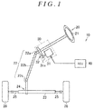
FIG. 1 is a configuration diagram depicting a general configuration of an electric power steering apparatus to which a vehicular control apparatus in the present embodiment is applied; -
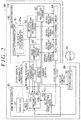
FIG. 2 is a block diagram depicting a general configuration of an ECU in the present embodiment; -
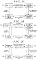
FIG. 3A is a block diagram depicting a general path of a reset path in the present embodiment; -
FIG. 3B is a block diagram depicting a general path of a reset path in the present embodiment; -
FIG. 3C is a block diagram depicting a general path of a reset path in the present embodiment; and -
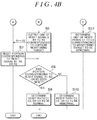
FIGS.4A and4B are sequence charts illustrating operations of a main microcomputer and a sub microcomputer in the present embodiment. - An embodiment will be described below in which a vehicular control apparatus in the invention is applied to an electric power steering apparatus (EPS). As depicted in
FIG. 1 , anEPS 10 includes asteering mechanism 20 that steers steeredwheels 26 based on a driver's operation of asteering wheel 21, anassist mechanism 30 that assists the driver's steering operation, and an electronic control unit (ECU) 40 serving as a vehicular control apparatus that controls theassist mechanism 30. - The
steering mechanism 20 includes asteering wheel 21 and asteering shaft 22 that rotates integrally with thesteering wheel 21. Thesteering shaft 22 has acolumn shaft 22a coupled to thesteering wheel 21, anintermediate shaft 22b coupled to a lower end of thecolumn shaft 22a, and apinion shaft 22c coupled to a lower end of theintermediate shaft 22b. A lower end of thepinion shaft 22c is coupled to a rack shaft 23 (to be exact, rack teeth on the rack shaft 23). Therefore, thesteering mechanism 20 converts rotary motion of thesteering shaft 22 into reciprocating linear motion of therack shaft 23 in an axial direction (a lateral direction inFIG. 1 ) via a rack-and-pinion mechanism 24 including pinion teeth provided at a tip of thepinion shaft 22c and rack teeth formed on therack shaft 23. The reciprocating linear motion is transmitted to each of the right and left steeredwheels 26 viatie rods 25 coupled to the opposite ends of therack shaft 23, to change a steered angle of the steeredwheels 26. - The
assist mechanism 30 includes amotor 31 that is a source of an assist force. A rotatingshaft 31a of themotor 31 is coupled to thecolumn shaft 22a via aspeed reduction mechanism 32. Thespeed reduction mechanism 32 reduces the speed of rotation output from themotor 31 to transmit the force of the rotation with the speed thereof reduced, to thecolumn shaft 22a. That is, the rotation force (torque) of themotor 31 is applied to thesteering shaft 22 as an assist force to assist the driver's steering operation. - The ECU 40 controls the
motor 31 based on detection results from various sensors provided in the vehicle. TheECU 40 sets a target assist force based on outputs from the various sensors, and controls a current supplied to themotor 31 so as to make the actual assist force equal to the target assist force. Driving control of themotor 31 by theECU 40 is started after completion of an initial check following switch-on of the ignition in the vehicle. - As depicted in
FIG. 2 , theECU 40 includes amain microcomputer 50 that performs driving control of themotor 31, asub microcomputer 60 that monitors operations of themain microcomputer 50, and a drivingcircuit 70 that supplies a current to themotor 31. - The
main microcomputer 50 includes amain clock 51 that generates a clock signal A based on a preset frequency, anarithmetic circuit 52 that executes a calculation for driving themotor 31, and areset control circuit 53 that resets circuits in themain microcomputer 50. - The clock signal A generated by the
main clock 51 is a signal that repeatedly becomes high and low at preset periods. Themain microcomputer 50 executes an arithmetic process based on the clock signal A. Themain clock 51 outputs the clock signal A to thesub microcomputer 60 at preset periods. - The
arithmetic circuit 52 acquires state variables (a steering torque and the like) detected by various sensors not depicted in the drawings and calculates a current command value allowing themotor 31 to generate an assist force in accordance with the steering torque. The current command value is a target value for a driving current for themotor 31 and corresponds to a target value for an output torque from themotor 31. Thearithmetic circuit 52 performs current feedback control in accordance with a deviation between an actual current value I obtained from acurrent sensor 80 and the current command value, and generates a motor control signal. Controlled variables in the present invention are, for example, the current command value and the motor control signal. - The
arithmetic circuit 52 also has aninternal watchdog circuit 52a and an internalarithmetic circuit 52b. Theinternal watchdog circuit 52a is provided to allow thearithmetic circuit 52 to make self-determination of whether or not thearithmetic circuit 52 is normal. Theinternal watchdog circuit 52a generates an internal watchdog signal B. The internal watchdog signal B is a pulse signal that changes between a high level and a low level at given periods when normal but that has its periodicity disturbed if thearithmetic circuit 52 becomes abnormal. Theinternal watchdog circuit 52a outputs the internal watchdog signal B to thesub microcomputer 60. The internalarithmetic circuit 52b calculates an answer signal Ca based on a question signal Cq received from thesub microcomputer 60, and outputs the answer signal Ca to thesub microcomputer 60. - The
sub microcomputer 60 includes aclock determining circuit 61, an internal watchdogsignal determining circuit 62, aQ&A watchdog circuit 63, a resetsignal determining circuit 64 that generates a reset signal R, and aquasi-abnormality control circuit 65 that brings a monitoring target signal into a quasi-abnormal state. Theclock determining circuit 61 determines whether or not themain microcomputer 50 is normal based on the clock signal A. The internal watchdogsignal determining circuit 62 determines whether or not themain microcomputer 50 is normal based on the internal watchdog signal B. TheQ&A watchdog circuit 63 determines whether or not themain microcomputer 50 is normal based on the answer signal Ca output from the internalarithmetic circuit 52b. The resetsignal determining circuit 64 generates a signal that allows resetting of an abnormal portion of the main microcomputer 50 (themain clock 51 or the arithmetic circuit 52), based on determination results from theclock determining circuit 61, the internal watchdogsignal determining circuit 62, and theQ&A watchdog circuit 63. The clock signal A, the internal watchdog signal B, and the answer signal Ca are monitoring target signals. - The
clock determining circuit 61 has asub clock 61a. Thesub clock 61a generates a clock signal A' that repeatedly becomes high and low at preset periods. The clock signal A' has a frequency corresponding to the clock signal A. For example, the frequency of the clock signal A' is set equal to the frequency of the clock signal A. Theclock determining circuit 61 determines whether or not themain clock 51 is normal based on the clock signal A output from themain clock 51 and the clock signal A' generated by thesub clock 61 a. - That is, the
clock determining circuit 61 compares the clock signal A with the clock signal A' and determines that themain clock 51 is normal when both signals have an equal value. Theclock determining circuit 61 compares the clock signal A with the clock signal A' and determines that themain clock 51 is abnormal when the signals have different values. Based on the determination of whether or not themain clock 51 is normal, theclock determining circuit 61 generates and outputs a determination signal DS1 to the resetsignal determining circuit 64. The determination signal DS1 contains not only the information indicating whether or not themain clock 51 is normal but also information indicating that a communication path for the clock signal A is normal and information indicating that the clock signal A' is also estimated to be normal. - The internal watchdog
signal determining circuit 62 receives the internal watchdog signal B output from theinternal watchdog circuit 52a in thearithmetic circuit 52. Based on the internal watchdog signal B, the internal watchdogsignal determining circuit 62 determines whether or not thearithmetic circuit 52 is normal. Specifically, the internal watchdogsignal determining circuit 62 determines that thearithmetic circuit 52 is abnormal when the internal watchdog signal B is output at a different period or when the internal watchdog signal B is not output. In contrast, when the internal watchdog signal B is received at given periods, the internal watchdogsignal determining circuit 62 determines that thearithmetic circuit 52 is normal. The internal watchdogsignal determining circuit 62 generates a determination signal DS2 based on the received internal watchdog signal B, and outputs the determination signal DS2 to the resetsignal determining circuit 64. - The
Q&A watchdog circuit 63 performs bidirectional communication with the internalarithmetic circuit 52b in thearithmetic circuit 52. Specifically, theQ&A watchdog circuit 63 outputs the question signal Cq to the internalarithmetic circuit 52b at preset periods. For example, the question signal Cq is a signal that questions the internalarithmetic circuit 52b about the result of calculation of a current command value I* executed by the internalarithmetic circuit 52b. The internalarithmetic circuit 52b executes a calculation in accordance with the question signal Cq to generate an answer signal Ca corresponding to the question signal Cq. TheQ&A watchdog circuit 63 can determine whether or not the arithmetic circuit 52 (to be exact, the internalarithmetic circuit 52b) is normal by checking whether or not the answer signal Ca is appropriate for the question signal Cq. When the answer signal Ca is appropriate, theQ&A watchdog circuit 63 determines that the internalarithmetic circuit 52b is normal. TheQ&A watchdog circuit 63 generates a determination signal DS3 based on the question signal Cq and the answer signal Ca and outputs the determination signal DS3 to the resetsignal determining circuit 64. - The
quasi-abnormality control circuit 65 performs control so as to bring one of the clock signal A, the internal watchdog signal B, and the answer signal Ca, which are the monitoring targets, into the quasi-abnormal state when the ignition is switched on. The quasi-abnormal state is not such a true abnormality as to affect the driving control of themotor 31 or the like but is a state that is not abnormal enough to affect the driving control of themotor 31 or the like. - Specifically, the
quasi-abnormality control circuit 65 outputs an abnormality causing signal E1 to themain clock 51 in order to cause a quasi-abnormal clock signal A to be generated. Upon receiving the abnormality causing signal E1, themain clock 51 generates and outputs a quasi-abnormal clock signal A to theclock determining circuit 61. Themain clock 51 may bring the clock signal A into the quasi-abnormal state by omitting the output of the clock signal A. In order to cause a quasi-abnormal internal watchdog signal B to be generated, thequasi-abnormality control circuit 65 outputs an abnormality causing signal E2 to the arithmetic circuit 52 (to be exact, theinternal watchdog circuit 52a). Upon receiving the abnormality causing signal E2, theinternal watchdog circuit 52a generates and outputs a quasi-abnormal internal watchdog signal B to the internal watchdogsignal determining circuit 62. The internal watchdog signal B may be brought into the quasi-abnormal state by omitting the output of the internal watchdog signal B. - In order to cause a quasi-abnormal answer signal Ca to be generated, the
quasi-abnormality control circuit 65 outputs an abnormality causing signal E3 to the arithmetic circuit 52 (to be exact, the internalarithmetic circuit 52b). Upon receiving the abnormality causing signal E3, thearithmetic circuit 52 generates and outputs a quasi-abnormal answer signal Ca to theQ&A watchdog circuit 63. For example, upon receiving the abnormality causing signal E3, thearithmetic circuit 52 generates an answer signal Ca with an inappropriate answer to the question signal Cq. The quasi-abnormal answer signal Ca may be output by omitting the output of the answer signal Ca or outputting the answer signal Ca at a different period. In order to cause a quasi-abnormal signal to be generated, thequasi-abnormality control circuit 65 outputs one of the abnormality causing signals E1 to E3 to the resetsignal determining circuit 64. - The
quasi-abnormality control circuit 65 also has a function to switch the monitoring target signal to be brought into the quasi-abnormal state each time the ignition is switched on. That is, thequasi-abnormality control circuit 65 determines the current monitoring target signal to be brought into the quasi-abnormal state based on which of the clock signal A, the internal watchdog signal B, and the answer signal Ca is the signal brought into the quasi-abnormal state during the initial check at the time of the last switch-on of the ignition. Specifically, when the last monitoring target signal is the clock signal A, the current monitoring target signal is set to be the internal watchdog signal B. When the current monitoring target signal is the internal watchdog signal B, the next monitoring target signal is set to be the answer signal Ca, and the monitoring target signal after the next monitoring target signal is set to be the clock signal A again. That is, each time the ignition is switched on, the monitoring target signal is switched among the clock signal A, the internal watchdog signal B, and the answer signal Ca in this order in rotation. - The reset
signal determining circuit 64 receives the determination signals DS1 to DS3. The resetsignal determining circuit 64 generates a reset signal R in accordance with the determination results in the determination signals DS1 to DS3. The reset signal R is a signal for resetting themain microcomputer 50 as a whole. The resetsignal determining circuit 64 outputs the reset signal R to thereset control circuit 53 in themain microcomputer 50. The reset signal R is generated, for example, when an abnormality is detected in the monitoring target signal while the vehicle is traveling. - The reset
signal determining circuit 64 can generate not only the reset signal R but also a signal for resetting a portion of themain microcomputer 50, which corresponds to one of the determination signals DS1 to DS3. Specifically, the resetsignal determining circuit 64 generates a reset signal R1 for resetting themain clock 51 when the determination signal DS1 is indicative of an abnormality. The resetsignal determining circuit 64 generates a reset signal R2 for resetting the arithmetic circuit 52 (to be exact, theinternal watchdog circuit 52a) when the determination signal DS2 is indicative of an abnormality. The resetsignal determining circuit 64 generates a reset signal R3 for resetting the arithmetic circuit 52 (to be exact, the internalarithmetic circuit 52b) when the determination signal DS3 is indicative of an abnormality. One of the reset signals R1 to R3 is generated, for example, when an abnormality is detected in the corresponding monitoring target signal during the initial check at the time of switch-on of the ignition. - The
reset control circuit 53 receives the reset signal R or one of the reset signals R1 to R3 output from the resetsignal determining circuit 64. Upon receiving the reset signal R, thereset control circuit 53 resets themain microcomputer 50 as a whole based on the reset signal R. That is, in addition to outputting one of the reset signals R1 to R3 to the corresponding portion of the main microcomputer 50 (themain clock 51 or the arithmetic circuit 52), thereset control circuit 53 outputs the reset signal to portions of the main microcomputer 50 (not depicted in the drawings) that are not directly related to the monitoring target signal. - When the reset signal R1 is input to the
reset control circuit 53, thereset control circuit 53 outputs the reset signal R1 to themain clock 51 to reset themain clock 51. When the reset signal R2 is input to thereset control circuit 53, thereset control circuit 53 outputs the reset signal R2 to theinternal watchdog circuit 52a to reset theinternal watchdog circuit 52a. When the reset signal R3 is input to thereset control circuit 53, thereset control circuit 53 outputs the reset signal R3 to the internalarithmetic circuit 52b to reset the internalarithmetic circuit 52b. - Reset paths will be described in detail that allow resetting of a portion of the
main microcomputer 50, which generates a monitoring target signal. As depicted inFIG. 3A , a reset path C1 for the main clock 51 (that outputs the clock signal A) includes themain clock 51, theclock determining circuit 61, the resetsignal determining circuit 64, thereset control circuit 53, and communication paths between these circuits. In the case where a quasi-abnormal clock signal A is generated in themain clock 51, when thereset control circuit 53 outputs the reset signal R1 to themain clock 51 to reset themain clock 51, the reset path C1 can be determined to function soundly. In contrast, when themain clock 51 is not reset in spite of the reset signal R1 output from thereset control circuit 53 to themain clock 51, the reset path C1 can be determined not to function soundly. - As depicted in
FIG. 3B , a reset path C2 for theinternal watchdog circuit 52a (that outputs the internal watchdog signal B) includes theinternal watchdog circuit 52a in thearithmetic circuit 52, the internal watchdogsignal determining circuit 62, the resetsignal determining circuit 64, thereset control circuit 53, and communication paths between these circuits. In the case where a quasi-abnormal internal watchdog signal B is generated in theinternal watchdog circuit 52a, when thereset control circuit 53 outputs the reset signal R2 to theinternal watchdog circuit 52a to reset theinternal watchdog circuit 52a, the reset path C2 can be determined to function soundly. In contrast, when theinternal watchdog circuit 52a is not reset in spite of the reset signal R2 output from thereset control circuit 53 to theinternal watchdog circuit 52a, the reset path C2 can be determined not to function soundly. - As depicted in
FIG. 3C , a reset path C3 for the internalarithmetic circuit 52b (that receives the question signal Cq and outputs the answer signal Ca) includes the internalarithmetic circuit 52b in thearithmetic circuit 52, theQ&A watchdog circuit 63, the resetsignal determining circuit 64, thereset control circuit 53, and communication paths between these circuits. In the case where a quasi-abnormal answer signal Ca is generated in the internalarithmetic circuit 52b, when thereset control circuit 53 outputs the reset signal R to the internalarithmetic circuit 52b to reset the internalarithmetic circuit 52b, the reset path C3 can be determined to function soundly. In contrast, when the internalarithmetic circuit 52b is not reset in spite of the reset signal R3 output from thereset control circuit 53 to the internalarithmetic circuit 52b, the reset path C3 can be determined not to function soundly. - Effects of the present embodiment will be described. First, the initial check on the reset paths C1 to C3 executed when the ignition is switched on will be described. The initial check is a characteristic part of the present embodiment. Description will be made below in accordance with a sequence chart in
FIGS.4A and4B . - While the ignition is off, the
main microcomputer 50 and thesub microcomputer 60 are supplied with no power and stopped. When the ignition is switched on, themain microcomputer 50 and thesub microcomputer 60 start to be driven and start the initial checks (steps S1 and S2). - The
sub microcomputer 60 determines the current monitoring target signal (step S3). If any signal is brought into the quasi-abnormal state during the last initial check, that signal is switched to a signal from a monitoring target different from the last monitoring target, which is set to be the current monitoring target. The sub microcomputer 60 (quasi-abnormality control circuit 65) outputs one of the abnormality causing signals E1 to E3 to the current monitoring target. - Specifically, when bringing the clock signal A into the quasi-abnormal state, the
quasi-abnormality control circuit 65 outputs the abnormality causing signal E1 to themain clock 51. When bringing the internal watchdog signal B into the quasi-abnormal state, thequasi-abnormality control circuit 65 outputs the abnormality causing signal E2 to theinternal watchdog circuit 52a. When bringing the answer signal Ca into the quasi-abnormal state, thequasi-abnormality control circuit 65 outputs the abnormality causing signal E3 to the internalarithmetic circuit 52b. Thequasi-abnormality control circuit 65 also outputs one of the abnormality causing signals E1 to E3 to the resetsignal determining circuit 64. - The
main microcomputer 50 brings the monitoring target signal (the clock signal A, the internal watchdog signal B, or the answer signal Ca) into the quasi-abnormal state based on the abnormality causing signal E1, E2, or E3 (step S4). - The
sub microcomputer 60 determines whether or not one of the determination signals DS1 to DS3 that corresponds to the signal (the clock signal A, the internal watchdog signal B, or the answer signal Ca) generated by the current monitoring target is indicative of an abnormality (step S5). In other words, thesub microcomputer 60 determines whether the determination signal DS1, DS2, or DS3 corresponding to the abnormality causing signal E1, E2, or E3, respectively, is indicative of an abnormality. - Specifically, when bringing the clock signal A into the quasi-abnormal state, the reset
signal determining circuit 64 receives the abnormality causing signal E1 output from thequasi-abnormality control circuit 65 and the determination signal DS1 output from theclock determining circuit 61. The resetsignal determining circuit 64 determines whether the determination signal DS1 corresponding to the abnormality causing signal E1 is indicative of an abnormality. In other words, the resetsignal determining circuit 64 determines whether or not the determination signal DS1 corresponding to the clock signal A output from the current monitoring target is abnormal. - When the determination signal DS1, DS2, or DS3 corresponding to the signal generated by the current monitoring target is indicative of an abnormality (YES in step S5), the
sub microcomputer 60 outputs the corresponding reset signal R1, R2, or R3 to the main microcomputer 50 (reset control circuit 53) (step S6). Specifically, to reset the abnormality in themain clock 51, which has resulted in generation of the determination signal DS1, the resetsignal determining circuit 64 in thesub microcomputer 60 outputs the reset signal R1 to thereset control circuit 53. - The
main microcomputer 50 receives the reset signal R1, R2, or R3 from thesub microcomputer 60 and resets the portion of themain microcomputer 50 corresponding to the reset signal R1, R2, or R3 (step S7) to end the process. For example, upon receiving the reset signal R1, themain microcomputer 50 resets themain clock 51. - The
sub microcomputer 60 determines whether the portion of themain microcomputer 50, which corresponds to the reset signal R1, R2, or R3, has been reset (step S8). Whether the portion has been reset can be determined, for example, depending on whether the corresponding determination signal DS1, DS2, or DS3 indicative of an abnormality has changed to indicate normality. - When the portion corresponding to the reset signal R1, R2, or R3 has been reset (in step S8, YES), the corresponding one of the reset paths C1 to C3 is determined to function normally, and the process is ended (step S9). In contrast, when the portion corresponding to the reset signal R1, R2, or R3 has not been reset (in step S8, NO), the corresponding reset path C1, C2, or C3 is determined not to function normally (step S10). The process is ended.
- In the determination in step S5 described above, when the determination signal DS1, DS2, or DS3 corresponding to the signal generated by the current monitoring target is not indicative of an abnormality in spite of the corresponding abnormality causing signal E1, E2, or E3 output from the sub microcomputer 60 (step S5, NO), the reset path C1, C2, or C3 corresponding to the monitoring target is determined to be abnormal (step S11). For example, if the determination signal DS1 is not indicative of an abnormality even though the clock signal A has been brought into the quasi-abnormal state, then for example, the
clock determining circuit 61 may have been abnormal or disconnection may have occurred on the communication path for the reset signal R1. - Thus, the check on the soundness of the reset path C1, C2, or C3 during the initial check is ended. Then, at the time of the next switch-on of the ignition, a signal different from the current monitoring target signal is set to be a monitoring target, and the corresponding reset path C1, C2, or C3 is checked for soundness. Consequently, all the reset paths C1 to C3 are sequentially checked for soundness.
- If the reset path C1, C2, or C3 is abnormal, a preset process such as stoppage of operation of the
ECU 40 itself is executed. This is because resetting cannot be executed due to an abnormality in the reset path C1, C2, or C3 corresponding to the signal brought into the quasi-abnormal state. - Effects of the present embodiment will be described. (1) The monitoring target signal is brought into the quasi-abnormal state during the initial check at the time of switch-on of the ignition to allow checking of whether all of the reset paths C1 to C3 are sound. During the initial check, a sufficient time cannot be taken, and thus, checking whether all the reset paths C1 to C3 are sound is temporally difficult. However, whether all the reset paths C1 to C3 are sound can be checked by switching the reset path to be checked for soundness each time the ignition is switched on. Thus, more reset paths C1 to C3 can be checked for soundness, and even upon becoming abnormal, the
main microcomputer 50 can be more reliably reset. This allows themain microcomputer 50 to function more reliably. - (2) During the initial check at the time of switch-on of the ignition, resetting is performed on each path to be checked for soundness, further reducing the time needed to check the reset paths for soundness. That is, compared to resetting the entire
main microcomputer 50, resetting only of the quasi-abnormal portion of themain microcomputer 50 enables a further reduction in the time from resetting of themain microcomputer 50 until themain microcomputer 50 returns to normal driving. - The present embodiment may be modified as follows. In the present embodiment, the signal output from the
main microcomputer 50 is brought into the quasi-abnormal state. However, the invention is not limited to this. For example, the signal output from thesub microcomputer 60 may be brought into the quasi-abnormal state, or a quasi-abnormality may be caused by preventing thesub microcomputer 60 from receiving the signals output from themain microcomputer 50. - In the present embodiment, the reset
signal determining circuit 64 is provided in thesub microcomputer 60. The invention is not limited to this. For example, the resetsignal determining circuit 64 may be provided in themain microcomputer 50 or outside themain microcomputer 50 and thesub microcomputer 60. - The present embodiment uses the
main microcomputer 50 and thesub microcomputer 60. However, the invention is not limited to this. For example, a CPU or an integrated circuit (IC) may be used. That is, any electronic component may be used. - In the present embodiment, driving of the
main microcomputer 50 is monitored by thesub microcomputer 60. However, the invention is not limited to this. That is, driving of thesub microcomputer 60 may be monitored by themain microcomputer 50, or themain microcomputer 50 and thesub microcomputer 60 may monitor each other. - In the present embodiment, all the reset paths C1 to C3 are checked for soundness by switching the reset path to be checked for soundness in rotation each time the ignition is switched on. However, the invention is not limited to this. That is, switching may be randomly executed among the the reset paths or the same reset path may be continuously checked for soundness.
- In the present embodiment, the frequency of the clock signal A' is set equal to the frequency of the clock signal A. However, the invention is not limited to this. For example, the frequencies of the clock signals A' and A may be set to have a divisor relation.
- In the present embodiment, the
sub clock 61a is provided in theclock determining circuit 61. However, thesub clock 61 a may be omitted from theclock determining circuit 61. In this case, whether or not an abnormality is present can be determined based on whether the frequency of themain clock 51 stored in theclock determining circuit 61 is equal to the frequency of the clock signal A. - In the present embodiment, the
quasi-abnormality control circuit 65 in thesub microcomputer 60 determines the signal to be brought into the quasi-abnormal state. However, the invention is not limited to this. For example, themain microcomputer 50 may be provided with thequasi-abnormality control circuit 65. - If a constraint on the time for the initial check is lax, then after the first resetting process during the initial check at the time of switch-on of the ignition, the second resetting process may be executed by bringing another monitoring target signal into the quasi-abnormal state again. That is, the resetting process may be executed a plurality of times within the time for the initial check.
- In the present embodiment, one of the clock signal A, the internal watchdog signal B, and the answer signal Ca is used as the monitoring target signal. However, the invention is not limited to this. For example, four or more signals may be monitored, or two signals may be monitored.
- In the present embodiment, when resetting is executed during the initial check at the time of switch-on of the ignition, the quasi-abnormal portion of the
main microcomputer 50 is reset using the reset signal R1, R2, or R3. However, the invention is not limited to this. That is, even when resetting is executed during the initial check, themain microcomputer 50 as a whole may be reset by outputting the reset signal R. - In the present embodiment, during the initial check at the time of switch-on of the ignition, the monitoring target signal is made quasi-abnormal to allow checking of the reset paths C1 to C3 for soundness. However, the invention is not limited to this. For example, the reset paths C1 to C3 may be checked for soundness after the ignition is switched off and before the
ECU 40 is powered off. - In the present embodiment, the vehicular control apparatus is embodied in the
ECU 40 in theEPS 10. However, the vehicular control apparatus may be used for applications other than theEPS 10. For example, the vehicular control apparatus may be applied to an ECU for any other in-vehicle system such as a steer-by-wire system.
Claims (5)
- A vehicular control apparatus comprising:a control circuit that controls an operation of a vehicle to generate a plurality of signals;a monitoring circuit that monitors the signals to monitor an operation of the control circuit;an abnormality causing circuit that selects one of the signals and that causes a quasi-abnormality in the selected signal; anda reset determining circuit that resets the control circuit when the selected signal is determined to be abnormal, whereinthe abnormality causing circuit switches the signal to be brought into a quasi-abnormal state from the selected signal to another signal each time the vehicle is powered on.
- The vehicular control apparatus according to claim 1, wherein
the reset determining circuit is provided in the monitoring circuit. - The vehicular control apparatus according to claim 1 or 2, wherein
the monitoring circuit generates signals similar to the signals generated by the control circuit, and an abnormality determining circuit is provided which determines whether each of the signals generated by the control circuit is abnormal by comparing the signal generated by the control circuit with corresponding one of the signals generated by the monitoring circuit. - The vehicular control apparatus according to any one of claims 1 to 3, wherein
the control circuit has a plurality of signal generating circuits each generating one of the signals in the control circuit, and
the reset determining circuit resets one of the signal generating circuits that generates the selected signal when the selected signal is determined to be abnormal. - The vehicular control apparatus according to any one of claims 1 to 4, wherein,
the control circuit has a clock generating circuit that generates a clock signal and an arithmetic circuit that calculates an controlled variable of the vehicle,
the arithmetic circuit has an internal watchdog circuit that generates an internal watchdog signal for monitoring an operation of the arithmetic circuit and an external monitoring circuit for monitoring an arithmetic function of the arithmetic circuit based on a request from the monitoring circuit, and
the signals monitored by the monitoring circuit are the clock signal generated by the clock generating circuit, the internal watchdog signal generated by the internal watchdog circuit, and an external monitoring signal generated by the external monitoring circuit.
Applications Claiming Priority (1)
| Application Number | Priority Date | Filing Date | Title |
|---|---|---|---|
| JP2015103940A JP6540227B2 (en) | 2015-05-21 | 2015-05-21 | Vehicle control device |
Publications (2)
| Publication Number | Publication Date |
|---|---|
| EP3095674A1 true EP3095674A1 (en) | 2016-11-23 |
| EP3095674B1 EP3095674B1 (en) | 2019-06-26 |
Family
ID=55970856
Family Applications (1)
| Application Number | Title | Priority Date | Filing Date |
|---|---|---|---|
| EP16169321.3A Active EP3095674B1 (en) | 2015-05-21 | 2016-05-12 | Vehicular control apparatus |
Country Status (4)
| Country | Link |
|---|---|
| US (1) | US9914474B2 (en) |
| EP (1) | EP3095674B1 (en) |
| JP (1) | JP6540227B2 (en) |
| CN (1) | CN106167040B (en) |
Families Citing this family (3)
| Publication number | Priority date | Publication date | Assignee | Title |
|---|---|---|---|---|
| JP6692763B2 (en) * | 2017-02-15 | 2020-05-13 | 株式会社デンソーテン | Control device and control program updating method |
| JP6848632B2 (en) * | 2017-04-10 | 2021-03-24 | 株式会社ジェイテクト | Vehicle control device |
| JP7136046B2 (en) * | 2019-08-15 | 2022-09-13 | 株式会社デンソー | Control device |
Citations (4)
| Publication number | Priority date | Publication date | Assignee | Title |
|---|---|---|---|---|
| US5360077A (en) * | 1992-06-01 | 1994-11-01 | Koyo Seiko Co., Ltd. | Electric power steering apparatus |
| US20080215913A1 (en) * | 2005-01-25 | 2008-09-04 | Yokogawa Electric Corporation | Information Processing System and Information Processing Method |
| DE102011054435A1 (en) * | 2010-10-22 | 2012-04-26 | Denso Corporation | Electronic control unit (ECU) for electric power steering apparatus of vehicle, detects abnormality of microcomputer, based on abnormality information received through clock control and monitoring signal lines |
| JP2013159120A (en) | 2012-02-01 | 2013-08-19 | Denso Corp | Electronic control device and electric power steering device using the same |
Family Cites Families (14)
| Publication number | Priority date | Publication date | Assignee | Title |
|---|---|---|---|---|
| GB1071171A (en) * | 1963-03-01 | 1967-06-07 | Standard Telephones Cables Ltd | Radio communication system |
| CN1013618B (en) * | 1985-09-05 | 1991-08-21 | 住友电气工业株式会社 | Detecting device for ground fault of electric equipment |
| US4847603A (en) * | 1986-05-01 | 1989-07-11 | Blanchard Clark E | Automatic closed loop scaling and drift correcting system and method particularly for aircraft head up displays |
| JPH03101493A (en) * | 1989-09-14 | 1991-04-26 | Sanee Denshi Kk | Monitor television monitoring device with optical sensor playing role of monitor function in deputy |
| JP3991384B2 (en) * | 1996-07-15 | 2007-10-17 | 株式会社デンソー | Electronic control unit |
| JP2000259444A (en) * | 1999-03-10 | 2000-09-22 | Nec Ibaraki Ltd | Data processor and its testing method |
| JP4534845B2 (en) * | 2005-04-08 | 2010-09-01 | 日産自動車株式会社 | Steering control device |
| JP4242405B2 (en) * | 2006-09-15 | 2009-03-25 | 三菱電機株式会社 | In-vehicle electronic control unit |
| JP4469886B2 (en) * | 2007-09-20 | 2010-06-02 | 日立オートモティブシステムズ株式会社 | Load drive circuit |
| JP2011043957A (en) * | 2009-08-20 | 2011-03-03 | Renesas Electronics Corp | Fault monitoring circuit, semiconductor integrated circuit, and faulty part locating method |
| EP2559985B1 (en) * | 2011-06-21 | 2016-10-19 | NSK Ltd. | Abnormality diagnosis method for torque detection device, and electric power steering device |
| JP5652434B2 (en) * | 2012-06-15 | 2015-01-14 | 株式会社デンソー | Motor control device and electric power steering device using the same |
| WO2014041596A1 (en) * | 2012-09-11 | 2014-03-20 | 三菱電機株式会社 | Safety controller |
| JP6098513B2 (en) * | 2012-10-23 | 2017-03-22 | 日本精工株式会社 | Torque detection device, electric power steering device, and vehicle |
-
2015
- 2015-05-21 JP JP2015103940A patent/JP6540227B2/en active Active
-
2016
- 2016-05-09 US US15/149,622 patent/US9914474B2/en active Active
- 2016-05-10 CN CN201610304348.9A patent/CN106167040B/en active Active
- 2016-05-12 EP EP16169321.3A patent/EP3095674B1/en active Active
Patent Citations (4)
| Publication number | Priority date | Publication date | Assignee | Title |
|---|---|---|---|---|
| US5360077A (en) * | 1992-06-01 | 1994-11-01 | Koyo Seiko Co., Ltd. | Electric power steering apparatus |
| US20080215913A1 (en) * | 2005-01-25 | 2008-09-04 | Yokogawa Electric Corporation | Information Processing System and Information Processing Method |
| DE102011054435A1 (en) * | 2010-10-22 | 2012-04-26 | Denso Corporation | Electronic control unit (ECU) for electric power steering apparatus of vehicle, detects abnormality of microcomputer, based on abnormality information received through clock control and monitoring signal lines |
| JP2013159120A (en) | 2012-02-01 | 2013-08-19 | Denso Corp | Electronic control device and electric power steering device using the same |
Also Published As
| Publication number | Publication date |
|---|---|
| CN106167040A (en) | 2016-11-30 |
| US20160339950A1 (en) | 2016-11-24 |
| CN106167040B (en) | 2020-02-21 |
| JP6540227B2 (en) | 2019-07-10 |
| EP3095674B1 (en) | 2019-06-26 |
| US9914474B2 (en) | 2018-03-13 |
| JP2016215875A (en) | 2016-12-22 |
Similar Documents
| Publication | Publication Date | Title |
|---|---|---|
| US10214235B2 (en) | Power steering device and power steering device control unit | |
| US9043089B2 (en) | Actuator control apparatus | |
| US10717462B2 (en) | Sensor device and electric power steering device using same | |
| US10017205B2 (en) | Control apparatus and control method of on-vehicle electronic equipment | |
| US9772249B2 (en) | Sensor device, motor control device, and electric power steering apparatus | |
| US11465683B2 (en) | Steering angle detection device | |
| EP3196096B1 (en) | Electric power steering device | |
| US10710521B2 (en) | Abnormality monitoring device and electric power steering device using same | |
| EP2161179A1 (en) | Electric power steering device | |
| EP3095674B1 (en) | Vehicular control apparatus | |
| US20190111968A1 (en) | Driver warning in electric power steering systems | |
| JP2013159120A (en) | Electronic control device and electric power steering device using the same | |
| EP3296185B1 (en) | Electric power steering device | |
| US9896125B2 (en) | Control apparatus and control method of on-vehicle electronic equipment | |
| JP6885171B2 (en) | Vehicle control device | |
| US10633018B2 (en) | External watchdog with integrated backward regeneration support | |
| KR20170065430A (en) | Apparatus for complex sensing | |
| JP2018008652A (en) | Steering device | |
| JP2018076072A (en) | Control device of electric power steering device | |
| JP2014076722A (en) | Motor controller | |
| JP2014117064A (en) | Motor controller | |
| CN111032483B (en) | Hardware-implemented motor control and platform for EPS | |
| KR100816393B1 (en) | How to check the motor status of the electric power steering system | |
| JP2014234072A (en) | Electric power steering device | |
| JP6287644B2 (en) | Control device for electric power steering device |
Legal Events
| Date | Code | Title | Description |
|---|---|---|---|
| PUAI | Public reference made under article 153(3) epc to a published international application that has entered the european phase |
Free format text: ORIGINAL CODE: 0009012 |
|
| AK | Designated contracting states |
Kind code of ref document: A1 Designated state(s): AL AT BE BG CH CY CZ DE DK EE ES FI FR GB GR HR HU IE IS IT LI LT LU LV MC MK MT NL NO PL PT RO RS SE SI SK SM TR |
|
| AX | Request for extension of the european patent |
Extension state: BA ME |
|
| STAA | Information on the status of an ep patent application or granted ep patent |
Free format text: STATUS: REQUEST FOR EXAMINATION WAS MADE |
|
| 17P | Request for examination filed |
Effective date: 20170518 |
|
| RBV | Designated contracting states (corrected) |
Designated state(s): AL AT BE BG CH CY CZ DE DK EE ES FI FR GB GR HR HU IE IS IT LI LT LU LV MC MK MT NL NO PL PT RO RS SE SI SK SM TR |
|
| RIC1 | Information provided on ipc code assigned before grant |
Ipc: B62D 5/04 20060101AFI20180831BHEP Ipc: B60R 16/02 20060101ALN20180831BHEP Ipc: B60W 50/04 20060101ALN20180831BHEP |
|
| GRAP | Despatch of communication of intention to grant a patent |
Free format text: ORIGINAL CODE: EPIDOSNIGR1 |
|
| STAA | Information on the status of an ep patent application or granted ep patent |
Free format text: STATUS: GRANT OF PATENT IS INTENDED |
|
| RIC1 | Information provided on ipc code assigned before grant |
Ipc: B60W 50/04 20060101ALN20181211BHEP Ipc: B62D 5/04 20060101AFI20181211BHEP Ipc: B60R 16/02 20060101ALN20181211BHEP |
|
| INTG | Intention to grant announced |
Effective date: 20190103 |
|
| RIN1 | Information on inventor provided before grant (corrected) |
Inventor name: KOZUKA, KENICHI |
|
| GRAS | Grant fee paid |
Free format text: ORIGINAL CODE: EPIDOSNIGR3 |
|
| GRAA | (expected) grant |
Free format text: ORIGINAL CODE: 0009210 |
|
| STAA | Information on the status of an ep patent application or granted ep patent |
Free format text: STATUS: THE PATENT HAS BEEN GRANTED |
|
| RAP1 | Party data changed (applicant data changed or rights of an application transferred) |
Owner name: JTEKT CORPORATION |
|
| RIN1 | Information on inventor provided before grant (corrected) |
Inventor name: KOZUKA, KENICHI |
|
| AK | Designated contracting states |
Kind code of ref document: B1 Designated state(s): AL AT BE BG CH CY CZ DE DK EE ES FI FR GB GR HR HU IE IS IT LI LT LU LV MC MK MT NL NO PL PT RO RS SE SI SK SM TR |
|
| REG | Reference to a national code |
Ref country code: GB Ref legal event code: FG4D |
|
| REG | Reference to a national code |
Ref country code: CH Ref legal event code: EP |
|
| REG | Reference to a national code |
Ref country code: AT Ref legal event code: REF Ref document number: 1147950 Country of ref document: AT Kind code of ref document: T Effective date: 20190715 |
|
| REG | Reference to a national code |
Ref country code: DE Ref legal event code: R096 Ref document number: 602016015793 Country of ref document: DE |
|
| REG | Reference to a national code |
Ref country code: IE Ref legal event code: FG4D |
|
| REG | Reference to a national code |
Ref country code: NL Ref legal event code: MP Effective date: 20190626 |
|
| PG25 | Lapsed in a contracting state [announced via postgrant information from national office to epo] |
Ref country code: FI Free format text: LAPSE BECAUSE OF FAILURE TO SUBMIT A TRANSLATION OF THE DESCRIPTION OR TO PAY THE FEE WITHIN THE PRESCRIBED TIME-LIMIT Effective date: 20190626 Ref country code: NO Free format text: LAPSE BECAUSE OF FAILURE TO SUBMIT A TRANSLATION OF THE DESCRIPTION OR TO PAY THE FEE WITHIN THE PRESCRIBED TIME-LIMIT Effective date: 20190926 Ref country code: AL Free format text: LAPSE BECAUSE OF FAILURE TO SUBMIT A TRANSLATION OF THE DESCRIPTION OR TO PAY THE FEE WITHIN THE PRESCRIBED TIME-LIMIT Effective date: 20190626 Ref country code: SE Free format text: LAPSE BECAUSE OF FAILURE TO SUBMIT A TRANSLATION OF THE DESCRIPTION OR TO PAY THE FEE WITHIN THE PRESCRIBED TIME-LIMIT Effective date: 20190626 Ref country code: HR Free format text: LAPSE BECAUSE OF FAILURE TO SUBMIT A TRANSLATION OF THE DESCRIPTION OR TO PAY THE FEE WITHIN THE PRESCRIBED TIME-LIMIT Effective date: 20190626 Ref country code: LT Free format text: LAPSE BECAUSE OF FAILURE TO SUBMIT A TRANSLATION OF THE DESCRIPTION OR TO PAY THE FEE WITHIN THE PRESCRIBED TIME-LIMIT Effective date: 20190626 |
|
| REG | Reference to a national code |
Ref country code: LT Ref legal event code: MG4D |
|
| PG25 | Lapsed in a contracting state [announced via postgrant information from national office to epo] |
Ref country code: LV Free format text: LAPSE BECAUSE OF FAILURE TO SUBMIT A TRANSLATION OF THE DESCRIPTION OR TO PAY THE FEE WITHIN THE PRESCRIBED TIME-LIMIT Effective date: 20190626 Ref country code: RS Free format text: LAPSE BECAUSE OF FAILURE TO SUBMIT A TRANSLATION OF THE DESCRIPTION OR TO PAY THE FEE WITHIN THE PRESCRIBED TIME-LIMIT Effective date: 20190626 Ref country code: BG Free format text: LAPSE BECAUSE OF FAILURE TO SUBMIT A TRANSLATION OF THE DESCRIPTION OR TO PAY THE FEE WITHIN THE PRESCRIBED TIME-LIMIT Effective date: 20190926 Ref country code: GR Free format text: LAPSE BECAUSE OF FAILURE TO SUBMIT A TRANSLATION OF THE DESCRIPTION OR TO PAY THE FEE WITHIN THE PRESCRIBED TIME-LIMIT Effective date: 20190927 |
|
| REG | Reference to a national code |
Ref country code: AT Ref legal event code: MK05 Ref document number: 1147950 Country of ref document: AT Kind code of ref document: T Effective date: 20190626 |
|
| PG25 | Lapsed in a contracting state [announced via postgrant information from national office to epo] |
Ref country code: PT Free format text: LAPSE BECAUSE OF FAILURE TO SUBMIT A TRANSLATION OF THE DESCRIPTION OR TO PAY THE FEE WITHIN THE PRESCRIBED TIME-LIMIT Effective date: 20191028 Ref country code: AT Free format text: LAPSE BECAUSE OF FAILURE TO SUBMIT A TRANSLATION OF THE DESCRIPTION OR TO PAY THE FEE WITHIN THE PRESCRIBED TIME-LIMIT Effective date: 20190626 Ref country code: SK Free format text: LAPSE BECAUSE OF FAILURE TO SUBMIT A TRANSLATION OF THE DESCRIPTION OR TO PAY THE FEE WITHIN THE PRESCRIBED TIME-LIMIT Effective date: 20190626 Ref country code: EE Free format text: LAPSE BECAUSE OF FAILURE TO SUBMIT A TRANSLATION OF THE DESCRIPTION OR TO PAY THE FEE WITHIN THE PRESCRIBED TIME-LIMIT Effective date: 20190626 Ref country code: RO Free format text: LAPSE BECAUSE OF FAILURE TO SUBMIT A TRANSLATION OF THE DESCRIPTION OR TO PAY THE FEE WITHIN THE PRESCRIBED TIME-LIMIT Effective date: 20190626 Ref country code: CZ Free format text: LAPSE BECAUSE OF FAILURE TO SUBMIT A TRANSLATION OF THE DESCRIPTION OR TO PAY THE FEE WITHIN THE PRESCRIBED TIME-LIMIT Effective date: 20190626 Ref country code: NL Free format text: LAPSE BECAUSE OF FAILURE TO SUBMIT A TRANSLATION OF THE DESCRIPTION OR TO PAY THE FEE WITHIN THE PRESCRIBED TIME-LIMIT Effective date: 20190626 |
|
| PG25 | Lapsed in a contracting state [announced via postgrant information from national office to epo] |
Ref country code: ES Free format text: LAPSE BECAUSE OF FAILURE TO SUBMIT A TRANSLATION OF THE DESCRIPTION OR TO PAY THE FEE WITHIN THE PRESCRIBED TIME-LIMIT Effective date: 20190626 Ref country code: SM Free format text: LAPSE BECAUSE OF FAILURE TO SUBMIT A TRANSLATION OF THE DESCRIPTION OR TO PAY THE FEE WITHIN THE PRESCRIBED TIME-LIMIT Effective date: 20190626 Ref country code: IS Free format text: LAPSE BECAUSE OF FAILURE TO SUBMIT A TRANSLATION OF THE DESCRIPTION OR TO PAY THE FEE WITHIN THE PRESCRIBED TIME-LIMIT Effective date: 20191026 Ref country code: IT Free format text: LAPSE BECAUSE OF FAILURE TO SUBMIT A TRANSLATION OF THE DESCRIPTION OR TO PAY THE FEE WITHIN THE PRESCRIBED TIME-LIMIT Effective date: 20190626 |
|
| PG25 | Lapsed in a contracting state [announced via postgrant information from national office to epo] |
Ref country code: TR Free format text: LAPSE BECAUSE OF FAILURE TO SUBMIT A TRANSLATION OF THE DESCRIPTION OR TO PAY THE FEE WITHIN THE PRESCRIBED TIME-LIMIT Effective date: 20190626 |
|
| PG25 | Lapsed in a contracting state [announced via postgrant information from national office to epo] |
Ref country code: PL Free format text: LAPSE BECAUSE OF FAILURE TO SUBMIT A TRANSLATION OF THE DESCRIPTION OR TO PAY THE FEE WITHIN THE PRESCRIBED TIME-LIMIT Effective date: 20190626 Ref country code: DK Free format text: LAPSE BECAUSE OF FAILURE TO SUBMIT A TRANSLATION OF THE DESCRIPTION OR TO PAY THE FEE WITHIN THE PRESCRIBED TIME-LIMIT Effective date: 20190626 |
|
| PG25 | Lapsed in a contracting state [announced via postgrant information from national office to epo] |
Ref country code: IS Free format text: LAPSE BECAUSE OF FAILURE TO SUBMIT A TRANSLATION OF THE DESCRIPTION OR TO PAY THE FEE WITHIN THE PRESCRIBED TIME-LIMIT Effective date: 20200224 |
|
| REG | Reference to a national code |
Ref country code: DE Ref legal event code: R097 Ref document number: 602016015793 Country of ref document: DE |
|
| PLBE | No opposition filed within time limit |
Free format text: ORIGINAL CODE: 0009261 |
|
| STAA | Information on the status of an ep patent application or granted ep patent |
Free format text: STATUS: NO OPPOSITION FILED WITHIN TIME LIMIT |
|
| PG2D | Information on lapse in contracting state deleted |
Ref country code: IS |
|
| 26N | No opposition filed |
Effective date: 20200603 |
|
| PG25 | Lapsed in a contracting state [announced via postgrant information from national office to epo] |
Ref country code: SI Free format text: LAPSE BECAUSE OF FAILURE TO SUBMIT A TRANSLATION OF THE DESCRIPTION OR TO PAY THE FEE WITHIN THE PRESCRIBED TIME-LIMIT Effective date: 20190626 |
|
| PG25 | Lapsed in a contracting state [announced via postgrant information from national office to epo] |
Ref country code: MC Free format text: LAPSE BECAUSE OF FAILURE TO SUBMIT A TRANSLATION OF THE DESCRIPTION OR TO PAY THE FEE WITHIN THE PRESCRIBED TIME-LIMIT Effective date: 20190626 Ref country code: LI Free format text: LAPSE BECAUSE OF NON-PAYMENT OF DUE FEES Effective date: 20200531 Ref country code: CH Free format text: LAPSE BECAUSE OF NON-PAYMENT OF DUE FEES Effective date: 20200531 |
|
| REG | Reference to a national code |
Ref country code: BE Ref legal event code: MM Effective date: 20200531 |
|
| GBPC | Gb: european patent ceased through non-payment of renewal fee |
Effective date: 20200512 |
|
| PG25 | Lapsed in a contracting state [announced via postgrant information from national office to epo] |
Ref country code: LU Free format text: LAPSE BECAUSE OF NON-PAYMENT OF DUE FEES Effective date: 20200512 |
|
| PG25 | Lapsed in a contracting state [announced via postgrant information from national office to epo] |
Ref country code: IE Free format text: LAPSE BECAUSE OF NON-PAYMENT OF DUE FEES Effective date: 20200512 Ref country code: GB Free format text: LAPSE BECAUSE OF NON-PAYMENT OF DUE FEES Effective date: 20200512 |
|
| PG25 | Lapsed in a contracting state [announced via postgrant information from national office to epo] |
Ref country code: BE Free format text: LAPSE BECAUSE OF NON-PAYMENT OF DUE FEES Effective date: 20200531 |
|
| PG25 | Lapsed in a contracting state [announced via postgrant information from national office to epo] |
Ref country code: MT Free format text: LAPSE BECAUSE OF FAILURE TO SUBMIT A TRANSLATION OF THE DESCRIPTION OR TO PAY THE FEE WITHIN THE PRESCRIBED TIME-LIMIT Effective date: 20190626 Ref country code: CY Free format text: LAPSE BECAUSE OF FAILURE TO SUBMIT A TRANSLATION OF THE DESCRIPTION OR TO PAY THE FEE WITHIN THE PRESCRIBED TIME-LIMIT Effective date: 20190626 |
|
| PG25 | Lapsed in a contracting state [announced via postgrant information from national office to epo] |
Ref country code: MK Free format text: LAPSE BECAUSE OF FAILURE TO SUBMIT A TRANSLATION OF THE DESCRIPTION OR TO PAY THE FEE WITHIN THE PRESCRIBED TIME-LIMIT Effective date: 20190626 |
|
| REG | Reference to a national code |
Ref country code: FR Ref legal event code: PLFP Year of fee payment: 8 |
|
| PGFP | Annual fee paid to national office [announced via postgrant information from national office to epo] |
Ref country code: DE Payment date: 20250402 Year of fee payment: 10 |
|
| PGFP | Annual fee paid to national office [announced via postgrant information from national office to epo] |
Ref country code: FR Payment date: 20250401 Year of fee payment: 10 |