EP3095550B1 - Vorgesintertes vorformhartlot zum verbinden von legierungsgussstücken - Google Patents
Vorgesintertes vorformhartlot zum verbinden von legierungsgussstücken Download PDFInfo
- Publication number
- EP3095550B1 EP3095550B1 EP16168659.7A EP16168659A EP3095550B1 EP 3095550 B1 EP3095550 B1 EP 3095550B1 EP 16168659 A EP16168659 A EP 16168659A EP 3095550 B1 EP3095550 B1 EP 3095550B1
- Authority
- EP
- European Patent Office
- Prior art keywords
- component
- psp
- braze
- braze material
- alloy
- Prior art date
- Legal status (The legal status is an assumption and is not a legal conclusion. Google has not performed a legal analysis and makes no representation as to the accuracy of the status listed.)
- Active
Links
Images


Classifications
-
- B—PERFORMING OPERATIONS; TRANSPORTING
- B23—MACHINE TOOLS; METAL-WORKING NOT OTHERWISE PROVIDED FOR
- B23K—SOLDERING OR UNSOLDERING; WELDING; CLADDING OR PLATING BY SOLDERING OR WELDING; CUTTING BY APPLYING HEAT LOCALLY, e.g. FLAME CUTTING; WORKING BY LASER BEAM
- B23K35/00—Rods, electrodes, materials, or media, for use in soldering, welding, or cutting
- B23K35/22—Rods, electrodes, materials, or media, for use in soldering, welding, or cutting characterised by the composition or nature of the material
- B23K35/24—Selection of soldering or welding materials proper
- B23K35/30—Selection of soldering or welding materials proper with the principal constituent melting at less than 1550 degrees C
- B23K35/3033—Ni as the principal constituent
- B23K35/304—Ni as the principal constituent with Cr as the next major constituent
-
- B—PERFORMING OPERATIONS; TRANSPORTING
- B22—CASTING; POWDER METALLURGY
- B22F—WORKING METALLIC POWDER; MANUFACTURE OF ARTICLES FROM METALLIC POWDER; MAKING METALLIC POWDER; APPARATUS OR DEVICES SPECIALLY ADAPTED FOR METALLIC POWDER
- B22F7/00—Manufacture of composite layers, workpieces, or articles, comprising metallic powder, by sintering the powder, with or without compacting wherein at least one part is obtained by sintering or compression
- B22F7/06—Manufacture of composite layers, workpieces, or articles, comprising metallic powder, by sintering the powder, with or without compacting wherein at least one part is obtained by sintering or compression of composite workpieces or articles from parts, e.g. to form tipped tools
- B22F7/08—Manufacture of composite layers, workpieces, or articles, comprising metallic powder, by sintering the powder, with or without compacting wherein at least one part is obtained by sintering or compression of composite workpieces or articles from parts, e.g. to form tipped tools with one or more parts not made from powder
-
- B—PERFORMING OPERATIONS; TRANSPORTING
- B23—MACHINE TOOLS; METAL-WORKING NOT OTHERWISE PROVIDED FOR
- B23K—SOLDERING OR UNSOLDERING; WELDING; CLADDING OR PLATING BY SOLDERING OR WELDING; CUTTING BY APPLYING HEAT LOCALLY, e.g. FLAME CUTTING; WORKING BY LASER BEAM
- B23K1/00—Soldering, e.g. brazing, or unsoldering
- B23K1/0008—Soldering, e.g. brazing, or unsoldering specially adapted for particular articles or work
- B23K1/0018—Brazing of turbine parts
-
- B—PERFORMING OPERATIONS; TRANSPORTING
- B23—MACHINE TOOLS; METAL-WORKING NOT OTHERWISE PROVIDED FOR
- B23K—SOLDERING OR UNSOLDERING; WELDING; CLADDING OR PLATING BY SOLDERING OR WELDING; CUTTING BY APPLYING HEAT LOCALLY, e.g. FLAME CUTTING; WORKING BY LASER BEAM
- B23K35/00—Rods, electrodes, materials, or media, for use in soldering, welding, or cutting
- B23K35/02—Rods, electrodes, materials, or media, for use in soldering, welding, or cutting characterised by mechanical features, e.g. shape
- B23K35/0222—Rods, electrodes, materials, or media, for use in soldering, welding, or cutting characterised by mechanical features, e.g. shape for use in soldering, brazing
- B23K35/0244—Powders, particles or spheres; Preforms made therefrom
-
- B—PERFORMING OPERATIONS; TRANSPORTING
- B23—MACHINE TOOLS; METAL-WORKING NOT OTHERWISE PROVIDED FOR
- B23K—SOLDERING OR UNSOLDERING; WELDING; CLADDING OR PLATING BY SOLDERING OR WELDING; CUTTING BY APPLYING HEAT LOCALLY, e.g. FLAME CUTTING; WORKING BY LASER BEAM
- B23K35/00—Rods, electrodes, materials, or media, for use in soldering, welding, or cutting
- B23K35/22—Rods, electrodes, materials, or media, for use in soldering, welding, or cutting characterised by the composition or nature of the material
- B23K35/24—Selection of soldering or welding materials proper
- B23K35/30—Selection of soldering or welding materials proper with the principal constituent melting at less than 1550 degrees C
- B23K35/3033—Ni as the principal constituent
-
- B—PERFORMING OPERATIONS; TRANSPORTING
- B23—MACHINE TOOLS; METAL-WORKING NOT OTHERWISE PROVIDED FOR
- B23K—SOLDERING OR UNSOLDERING; WELDING; CLADDING OR PLATING BY SOLDERING OR WELDING; CUTTING BY APPLYING HEAT LOCALLY, e.g. FLAME CUTTING; WORKING BY LASER BEAM
- B23K35/00—Rods, electrodes, materials, or media, for use in soldering, welding, or cutting
- B23K35/22—Rods, electrodes, materials, or media, for use in soldering, welding, or cutting characterised by the composition or nature of the material
- B23K35/24—Selection of soldering or welding materials proper
- B23K35/30—Selection of soldering or welding materials proper with the principal constituent melting at less than 1550 degrees C
- B23K35/3046—Co as the principal constituent
-
- C—CHEMISTRY; METALLURGY
- C22—METALLURGY; FERROUS OR NON-FERROUS ALLOYS; TREATMENT OF ALLOYS OR NON-FERROUS METALS
- C22C—ALLOYS
- C22C19/00—Alloys based on nickel or cobalt
- C22C19/03—Alloys based on nickel or cobalt based on nickel
- C22C19/05—Alloys based on nickel or cobalt based on nickel with chromium
- C22C19/051—Alloys based on nickel or cobalt based on nickel with chromium and Mo or W
- C22C19/057—Alloys based on nickel or cobalt based on nickel with chromium and Mo or W with the maximum Cr content being less 10%
-
- B—PERFORMING OPERATIONS; TRANSPORTING
- B32—LAYERED PRODUCTS
- B32B—LAYERED PRODUCTS, i.e. PRODUCTS BUILT-UP OF STRATA OF FLAT OR NON-FLAT, e.g. CELLULAR OR HONEYCOMB, FORM
- B32B15/00—Layered products comprising a layer of metal
- B32B15/01—Layered products comprising a layer of metal all layers being exclusively metallic
-
- B—PERFORMING OPERATIONS; TRANSPORTING
- B32—LAYERED PRODUCTS
- B32B—LAYERED PRODUCTS, i.e. PRODUCTS BUILT-UP OF STRATA OF FLAT OR NON-FLAT, e.g. CELLULAR OR HONEYCOMB, FORM
- B32B2305/00—Condition, form or state of the layers or laminate
- B32B2305/80—Sintered
-
- B—PERFORMING OPERATIONS; TRANSPORTING
- B32—LAYERED PRODUCTS
- B32B—LAYERED PRODUCTS, i.e. PRODUCTS BUILT-UP OF STRATA OF FLAT OR NON-FLAT, e.g. CELLULAR OR HONEYCOMB, FORM
- B32B2311/00—Metals, their alloys or their compounds
- B32B2311/22—Nickel or cobalt
-
- C—CHEMISTRY; METALLURGY
- C21—METALLURGY OF IRON
- C21D—MODIFYING THE PHYSICAL STRUCTURE OF FERROUS METALS; GENERAL DEVICES FOR HEAT TREATMENT OF FERROUS OR NON-FERROUS METALS OR ALLOYS; MAKING METAL MALLEABLE, e.g. BY DECARBURISATION OR TEMPERING
- C21D9/00—Heat treatment, e.g. annealing, hardening, quenching or tempering, adapted for particular articles; Furnaces therefor
- C21D9/50—Heat treatment, e.g. annealing, hardening, quenching or tempering, adapted for particular articles; Furnaces therefor for welded joints
Definitions
- the present disclosure generally relates to brazes for joining alloy castings.
- Some articles formed from superalloys include a single crystal and are formed using casting.
- casting a single crystal may be difficult, leading to relatively high rejection rates due to defects in the cast article.
- nozzle guide vanes for gas turbine engines may be cast as a single crystal, and this may restrict design complexity of the nozzle guide vanes.
- DE 10 2005 059299 discloses a process for repairing a turbine component of a turbomachine, as well as a sintered preform used in the process and a high gamma-prime nickel-base superalloy component repaired thereby.
- the sintered preform contains a sintered mixture of powders of a cobalt-base braze alloy and a cobalt-base wear-resistant alloy.
- the braze alloy constitutes at least about 10 up to about 35 weight percent of the sintered preform and contains a melting point depressant such as boron.
- the preform is formed by mixing powders of the braze and wear-resistant alloys to form a powder mixture, and then sintering the powder mixture.
- a surface portion of the turbine component is removed to expose a subsurface portion, followed by diffusion bonding of the preform to the subsurface portion to form a wear-resistant repair material containing the braze alloy dispersed in a matrix of the wear-resistant alloy.
- US 4,209,348 discloses nickel base superalloy single crystal articles formed of a particular composition and heat treated.
- the resultant articles are substantially free from the grain boundary strengtheners such as carbon, boron, and zirconium and contain only a limited amount of cobalt.
- the alloy composition the alloys have a high incipient melting temperature.
- the heat treatment process homogenizes the microstructure, and refines the gamma prime morphology.
- US 7,845,549 discloses a method of making a braze preform that includes: providing a mixture of a brazing alloy in metallic powder form and a binder; melting the binder and forming the mixture into a preform having a preselected shape; removing a majority of the binder from the preform; and heating the preform to remove the remainder of the binder and to sinter the metallic powder together.
- the preform may include a wear-resistant material therein. Such preforms may be used to form a braze joint between two metallic components, or to produce a metallic component with a wearcoated surface.
- US 2014/154082 A1 discloses a method for repairing a damaged portion of a gas turbine blade comprising: providing a preform comprising a low-melt alloy material and a base alloy material; locating the preform on the gas turbine engine blade damaged portion; and heat treating the preform and the blade such that the preform is brazed to the blade.
- the method involves providing a preform comprising 70 to 80 % by weight base alloy material and 30 to 20 % by weight low-melt allow material based on the total weight of the preform before heat treatment.
- the method includes positioning a first component comprising a first metal or alloy and a second component comprising a second metal or alloy to each other to define a joint region between adjacent portions of the first component and the second component.
- the method also includes positioning a pre-sintered preform (PSP) braze material in the joint region.
- the PSP braze material includes a wide gap braze material as defined in claim 1.
- the method further includes heating the PSP braze material to form a molten braze alloy and cooling the molten braze alloy to join the first and second components.
- the disclosure also describes an assembly that includes a first component comprising a first metal or alloy and a second component comprising a second metal or alloy.
- the first component and second component are positioned adjacent to each other to define a joint region between adjacent portions of the first component and the second component.
- the assembly also includes a pre-sintered preform (PSP) braze material as defined in claim 7 disposed in the joint region and a heat source for heating the PSP braze material disposed in the joint region.
- PSP pre-sintered preform
- the disclosure describes assemblies, systems, and techniques for joining a first component including a metal or alloy and a second component including a metal or alloy using a pre-sintered preform (PSP) braze material.
- the PSP braze material includes a wide gap braze material, and may include a powder that has been sintered to reduce porosity.
- the wide gap braze material is a Ni-based wide gap braze material.
- braze foils have been formed using a melting spinning technique, which results in thin foils having an amorphous microstructure.
- melting spinning is suitable for many braze alloys, some of these braze alloys may possess mechanical and chemical properties (e.g., mechanical strength and high temperature oxidation resistance) that make the braze alloys unsuitable for use in high temperature oxidative environments.
- the PSP braze materials described herein may, after brazing, result in alloys that have properties suitable for use in high temperature oxidative environments.
- the PSP braze materials are nickel-based alloys.
- the PSP braze materials may be used to join components that include a Ni-based alloy or a Co-based alloy.
- the PSP braze materials may possess mechanical and chemical properties (e.g., mechanical strength and high temperature oxidation resistance) that make the braze alloys suitable for use in high temperature oxidative environments
- the PSP braze materials may facilitate manufacture of articles for high temperature mechanical systems in multiple components, which are then joined using the PSP braze materials. This may reduce cost of manufacture due to lower defect levels in the components, facilitate more complex geometry, or the like.
- the PSP braze materials also may provide advantages compared to powder braze materials. For example, the PSP braze materials may result in reduced porosity in the braze joint compared to braze joints formed using a powder, which may improve mechanical properties of the braze joint. Further, the PSP braze materials may be easier to position in the joint region and result in a more uniform braze joint.
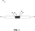
- FIG. 1 is a conceptual and schematic diagram illustrating an example assembly 10 for joining a first component 12 including a metal or alloy and a second component 14 including a metal or alloy using a pre-sintered preform (PSP) braze material 16.
- first component 12 and second component 14 may be joined to form an article or a portion of an article that is part of a high temperature mechanical system.
- first component 12 and second component 14 may be joined to form an article or a portion of nozzle guide vane (NGV) that is used in a high pressure or intermediate pressure stage in a gas turbine engine.
- the article may include another component of a high temperature mechanical system, such as another component of a gas turbine engine.
- the article may include a gas turbine engine blade, gas turbine engine vane, blade track, combustor liner, or the like.
- first component 12 and second component 14 includes a metal or alloy.
- first component 12 and second component 14 include substantially the same (e.g., the same or nearly the same) metal or alloy.
- first component 12 and second component 14 include different metals or alloys.
- each of first component 12 and second component 14 may include a Ni-, Co-, Fe-based superalloy, or the like.
- First component 12 and second component 14 including a superalloy may include other additive elements to alter its mechanical and chemical properties, such as toughness, hardness, temperature stability, corrosion resistance, oxidation resistance, and the like, as is known in the art.
- first component 12 and second component 14 may be utilized in first component 12 and second component 14, including, for example, Ni-based alloys available from Martin-Marietta Corp., Bethesda, MD, under the trade designation MAR-M246, MAR-M247; Ni-based alloys available from Cannon-Muskegon Corp., Muskegon, MI, under the trade designations CMSX-3, CMSX-4, CMSX-10, and CM-186; Co-based alloys available from Martin-Marietta Corp., Bethesda, MD, under the trade designation MAR-M509; and the like.
- the compositions of CMSX-3 and CMSX-4 are shown below in Table 1. Table 1 CMSX-3 (wt. %) CMSX-4 (wt. %) Cr 8 6.5 Al 5.6 5.6 Ti 1 1 Co 5 10 W 8 6 Mo 0.6 0.6 Ta 6 6 Hf 0.1 0.1 Re 3 Ni Balance Balance
- first component 12 and second component 14 may be made using at least one of casting, forging, powder metallurgy, or additive manufacturing. In some examples, first component 12 and second component 14 are made using the same process, while in other examples, first component 12 and second component 14 are made using different processes.
- first component 12 and second component 14 may define a more complex geometry, including simple or complex curves, overhangs, undercuts, internal cavities, or the like.
- First component 12 defines at least one joint surface 16.
- second component 14 defines at least one joint surface 18.
- joint surfaces 16 and 18 may define complementary shapes.
- FIG. 1 illustrates joint surfaces 16 and 18 as substantially flat surfaces.
- joint surfaces 16 and 18 may define other, more complex shapes, including, for example, simple or complex curves, overhangs, undercuts, apertures, annuluses, or the like.
- First component 12 and second component 14 are positioned such that joint surfaces 16 and 18 are adjacent to each other and define a joint location 22.
- Joint location 22 may include any kind of simple or complex joint, including, for example, at least one of a bridle joint, a butt joint, a miter join, a dado joint, a groove joint, a tongue and groove joint, a mortise and tenon joint, a birdsmouth joint, a halved joint, a biscuit joint, a lap joint, a double lap joint, a dovetail joint, or a splice joint. Consequently, joint surfaces 16 and 18 may have any corresponding geometries to define the surfaces of the joint location 22.
- first component 12 may define a mortise (a cavity) and second component 14 may define a tenon (a projection that inserts into the mortise).
- first component 12 may define a half lap, a bevel lap, or the like, and second component 14 may define a complementary half lap bevel lap, or the like.
- assembly 10 may include a clamp, press, or other mechanism for exerting pressure between first joint surface 16 and second joint surface 18 during the brazing technique.
- the pressure between first joint surface 16 and second joint surface 18 may facilitate formation of the braze joint, e.g., by helping to at least one of maintain the gap of joint region 22, to promote flow of PSP braze material 20, and to evacuate any gases or porosity in PSP braze material 20, which reduces porosity in the braze joint.
- PSP braze material 20 Disposed in joint or joint location 22 is a PSP braze material 20.
- PSP braze material 20 is a wide gap braze material.
- PSP braze material 20 may include a powder mixture that has been sintered to form a pre-sintered preform. Sintering may reduce porosity compared to the powder, which may reduce porosity in joint region 22 during and after formation of the braze joint.
- PSP braze material 20 is a Ni-based wide gap braze alloy.
- PSP braze material 20 may include greater amounts of alloying elements that some other braze materials used in braze foils, which may contribute to improved mechanical properties, chemical properties, or both compared to some other braze materials used in braze foils.
- PSP braze material 20 may possess sufficient mechanical strength and high temperature oxidation resistance to be used in a nozzle guide vane in a gas turbine engine.
- PSP braze material 20 may include both a braze alloy powder (a low-melt powder composition) and a superalloy powder (a high-melt powder composition).
- the low-melt alloy powder composition is an alloy, or a mixture of alloys, that substantially melts below the braze temperature (hence the name "low-melt” or "braze powder”).
- the high-melt alloy powder composition is an alloy, or a mixture of alloys, that remains substantially unmelted at the braze temperature, because the composition has a melting temperature above the braze temperature (hence the name "high-melt” or "superalloy powder").
- the braze alloy powder and the superalloy powder may have specific powder mesh sizes, and may be produced by induction melting the braze alloy or the superalloy powder, respectively, in vacuum or an argon atmosphere, followed by argon gas atomization.
- Each individual powder component used in PSP braze material 20 may be analyzed to confirm the particle size and chemical compositions.
- the low-melt powder composition includes an alloy or a mixture of alloys that melt at a temperature below about 1232°C (about 2250° F), with the alloy or mixture of alloys being selected so that the low-melt powder composition as a whole substantially melts at a temperature between about 1093°C (about 2000°F) and about 1204°C (about 2200°F).
- the high-melt alloy powder composition may include a single high-melt alloy or a mixture of alloys that melts at a temperature of greater than about 1315°C (about 2400° F).
- the low-melt powder composition may include one or more alloy powders and includes between about 50 wt. % and about 70 wt. % Ni, between about 8 wt. % and about 20 wt. % Cr, between about 8 wt. % and about 15 wt. % Ta, between about 4 wt. % and about 10 wt. % Co, between about 2 wt. % and about 7 wt. % Al, up to about 2.25 wt. % B, and up to about 2.25 wt. % Si, and has a compositional melting range of between about 1093°C (about 2000°F) and about 1204°C (about 2200°F).
- the low-melt powder composition also includes up to about 1 wt. % each of at least one of Ti, W, Mo, Re, Nb, Hf, Pd, Pt, Ir, Ru, C, Si, P, Fe, Ce, La, Y, or Zr.
- the low-melt alloy powder comprises a mixture of two or more low-melt alloys.
- a low-melt alloy powder may include (a) about 35% of a first low-melt powder including about 74 wt. % Ni, about 6 wt. % Cr, about 6 wt. % Al, about 12 wt. % Co, and about 2 wt.
- a second low-melt powder including about 42 wt. % Ni, about 31 wt. % Cr, about 26 wt. % Ta, and about 1 wt. % B, with a liquidus temperature of about 1232°C (about 2250° F); and (c) about 20 wt. % of a third low-melt powder including about 64 wt. % Ni, about 6 wt. % Al, about 8 wt. % Co, about 4 wt. % W, about 4 wt. % Ta, about 3 wt. % Si, about 1 wt. % Re, about 1 wt. % Nb, and about 1 wt. % B, with a liquidus temperature of about 1093°C (about 2000° F).
- the high-melt powder composition may include an alloy or mixture of alloys with a chemistry that is the similar to or substantially the same (e.g., the same or nearly the same) as the alloy in first component 12, second component 14, or both.
- the high-melt powder composition may include between about 50 wt. % and about 70 wt. % Ni, between about 2 wt. % and about 10 wt. % Cr, between about 2 wt. % and about 10 wt. % Ta, between about 5 wt.
- the high-melt powder composition also may include up to about 1 wt. % each of at least one of Ti, Nb, C, B, Si, or Zr.
- the high-melt powder composition includes between about 55 wt. % and about 60 wt. % Ni, about 7 wt. % Cr, about 6 wt. % Ta, about 12 wt. % Co, about 6 wt. % Al, about 3 wt. % Re, about 1.5 wt. % Hf, and about 5 wt. % W.
- PSP braze material 20 may include a powder mixture consisting of between about 20 wt. % and about 80 wt. % low-melt powder composition and a balance high-melt powder composition (a ratio of between about 1:4 and about 4:1 low-melt:high-melt powder).
- braze alloy powder may be a mixture of more than one braze alloys which are all powder.
- the ratio may be between about 1:3 and about 3:1 low-melt:high-melt powder, such as a ratio between about 1:2 and about 2:1 low-melt:high-melt powder, or a ratio between about 1:1 and about 1:1.5 low-melt: high-melt powder.
- PSP braze material 20 may include between about 40 wt. % and about 50 wt. % low-melt alloy powder and between about 50 wt. % and about 60 wt. % high-melt powder, such as about 45 wt. % low-melt alloy powder and about 55 wt. % high-melt powder.
- PSP braze material 20 includes between about 50 wt. % and about 70 wt. % Ni, between about 10 wt. % and about 15 wt. % Cr, between about 8 wt. % and about 10 wt. % Ta, between about 8 wt. % and about 10 wt. % Co, between about 4 wt. % and about 7 wt. % Al, between about 2 wt. % and about 4 wt. % W, between about 1 wt. % and about 2 wt. % Re, about 1 wt. % Mo, about 1 wt.
- PSP braze material 20 may include between about 50 wt. % and about 70 wt. % Ni, between about 10 wt. % and about 15 wt. % Cr, between about 8 wt. % and about 10 wt. % Ta, between about 8 wt. % and about 10 wt. % Co, between about 4 wt. % and about 7 wt. % Al, between about 2 wt. % and about 4 wt.
- % W between about 1 wt. % and about 2 wt. % Re, between about 0.5 wt. % and about 1 wt. % Mo, between about 0.5 wt. % and about 1 wt. % Hf, between about 0.1 wt. % and about 0.5 wt. % Nb, between about 0.05 wt. % and about 3 wt. % Si, and between about 0.5 wt. % and about 2 wt. % B.
- PSP braze material 20 that includes higher Al content may possess improved high-temperature oxidation resistance properties compared to PSP braze material 20 with lower Al content.
- increasing Ta content in PSP braze material 20 may improve mechanical properties of the braze joint compared to lower Ta content.
- Ta may strengthen the gamma and gamma prime phases by increasing lattice mismatches.
- PSP braze material 20 may be formed by mixing an alloy powder or multiple alloy powders in a selected composition, then sintering the powder while disposed in a mold to form a sintered preform with reduced porosity.
- the sintering temperature and the duration of the sintering may depend at least in part on the composition of the alloy powder or multiple alloy powders.
- the sintered powder may then be cut or machined into a predetermined shape.
- the predetermined shape may correspond to a shape of joint region 22.
- joint region 22 may include a relatively simple geometry as shown in FIG. 1 , or may include a more complex geometry, e.g., multiple planes or surfaces, simple or complex curves, overhangs, undercuts, internal cavities, or the like.
- the sintered powder may be cut or machined into a relatively simple shape, or a more complex, e.g., including curvature, angles, apertures, or the like to form PSP braze material 20.
- PSP braze material 20 may include a substantially two-dimensional shape (e.g., a plane) or a three-dimensional shape (e.g., including curvature, planes at angles with respect to one another, and the like).
- PSP braze material 20 may define a thickness (e.g., in the direction between first joint surface 16 and second joint surface 18) that is less than or equal to about 127 micrometers (about 0.005 inch). In some examples, PSP braze material 20 may define a thinner thickness, such as about 51 micrometers (about 0.002 inch). In other examples, PSP braze material 20 may define a greater thickness, such as up to about 1524 micrometers (about 0.060 inch), or about 1016 micrometers (about 0.040 inch).
- alloys with desirable mechanical and chemical may be utilized in a brazing technique to join first component 12 and second component 14.
- the resulting braze joint may possess sufficient mechanical strength and high temperature oxidation resistance to be utilized in a high temperature mechanical system, such as a nozzle guide vane in a gas turbine engine.
- the braze joint may include reduced porosity compared to a joint formed using a braze powder, and positioning of the braze material may be easier and more precise than with a braze powder.
- PSP braze material 20 may facilitate using brazing to join components used in a high temperature mechanical system, which may allow formation of an article from multiple, smaller components, easing or reducing the cost of forming the article.
- FIG. 2 is a flow diagram illustrating an example technique for joining a first component including a metal or alloy and a second component including a metal or alloy using a pre-sintered preform (PSP) braze material.
- PPS pre-sintered preform
- first joint surface 16 and second joint surface 18 of first and second component 12 and 14, respectively may be inspected and cleaned. This cleaned joint surfaces 16 and 18 may produce a stronger braze joint than uncleaned joint surfaces.
- first component 12 and second component 14 may be positioned so that joint surfaces 16 and 18 are near each other.
- the geometry of joint region 22 may depend on the type of joint defined by joint surfaces 16 and 18 and may include, for example, a bridle joint, a butt joint, a scarf joint, a miter join, a dado joint, a groove joint, a tongue and groove joint, a mortise and tenon joint, a birdsmouth joint, a halved joint, a biscuit joint, a lap joint, a double lap joint, a dovetail joint, or a splice joint.
- the technique of FIG. 2 also include disposing PSP braze material 20 in joint region 22 (34).
- PSP braze material 20 may define a predetermined shape that at least partially corresponds to the geometry of joint region 22.
- joint region 22 may include a relatively simple geometry or a more complex geometry
- PSP braze material 20 may be cut or machined into a relatively simple shape, or a more complex shape, e.g., including curvature, angles, apertures, or the like.
- PSP braze material 20 is disposed in joint region 22 such that surface of PSP braze material 20 contacts joint surfaces 16 and 18.
- a clamp, press, or other mechanism may be used to compress PSP braze material 20 between joint surfaces 16 and 18 to cause intimate contact between joint surfaces 16 and 18 and surfaces of PSP braze material 20.
- the technique of FIG. 2 further includes heating PSP braze material 20 to melt at least part of PSP braze material (36).
- PSP braze material 20 may be heated in a furnace or other closed retort, and first component 12 and second component 14 may be heated with PSP braze material 20.
- the furnace or closed retort may enclose a vacuum or substantially inert atmosphere (e.g., an atmosphere including constituents that substantially do not react with components 12 and 14 and PSP braze material 20 at the temperatures and pressures experienced by the interior of the furnace or closed retort).
- PSP braze material 20 may be heated at a braze temperature of between about 1093°C (about 2000° F) and about 1288°C (about 2350° F), such as a braze temperatures of about 1260°C (about 2300° F).
- the time for which PSP braze material 20 is heated at the braze temperature may vary from about 10 minutes to about 60 minutes, for example between about 20 to 30 minutes.
- PSP braze material 20 is allowed to cool, for example to ambient temperature, to form a solid and join first component 12 and second component 14 (38).
- PSP braze material 20 may be cooled in a vacuum or inert gas furnace to about 650°C (about 1200° F) at a rate that is slow enough to avoid thermal distortion, followed by cooled under flowing inert gas to about 65°C (about 150° F) or less.
- the article including first component 12 and second component 14 joined by PSP braze material 20 may optionally be subjected to a diffusion heat treatment cycle to homogenize joint region 22.
- the diffusion heat treatment may be performed at temperatures between about 0°C (about 0°F) and about 222 °C (about 400°F) below the braze temperature (e.g., below the highest braze temperature used in a stepped heat treatment), and for times of up to about 24 hours.
- the post-brazing diffusion heat treatment cycle may include a stepped diffusion heat treatment cycle at a temperature of about 1149°C (about 2100°F for about 1 hour to about 18 hours.
- the article including first component 12 and second component 14 joined by PSP braze material 20 is disposed in a vacuum or inert atmosphere.
- the stepped diffusion heat treatment cycle may include heating the article including PSP braze material 20, first component 12, and second component 14 at a rate of between about 11°C/minute (about 20°F/minute) and about 22°C/minute (about 40°F/minute) to a first temperature of between about 982°C (about 1800°F) and about 1093°C (about 2000° F).
- the article may be held at the first temperature for about 30 minutes to about 4 hours.
- the stepped heat treatment may also include heating the article to a second temperature of between about 1038°C (about 1900° F) and about 1149°C (about 2100° F) at a rate of between about 5.6°C/minute (about 10°F/minute) and about 16.7°C/minute (about 30°F/minute).
- the article may be held at the second temperature for between about 1 hour and about 4 hours.
- the stepped heat treatment further includes heating the article to a third temperature of between about 1066°C (about 1950° F) and about 1177°C (about 2150° F) at a rate of between about 2.8°C/minute (about 5°F/minute) and about 11°C/minute (about 20°F/minute).
- the article may be held at the third temperature for between about 1 hour and about 4 hours.
- the stepped heat treatment also may include heating the article to a fourth temperature of between about 1093°C (about 2000° F) and about 1204°C (about 2200° F) at a rate of between about 2.8°C/minute (about 5°F/minute) and about 11°C/minute (about 20°F/minute).
- the article may be held at the fourth temperature for between about 6 hours and about 24 hours.
- the article may be heated at a rate of about 16.7°C/minute (about 30°F/minute) a first temperature of about 1038°C (about 1900° F) and held at about 1038°C for about 1 hour to about 2 hours.
- the article then may be heated to a second temperature of about 1093°C (about 2000° F) at a rate of about 11°C/minute (about 20°F/minute) and held at about 1093°C for about 1 hour to about 2 hours.
- the article then may be heated to a third temperature of about 1121°C (about 2050° F) at a rate of about 5.6°C/minute (about 10°F/minute) and held at about 1121°C for about 1 hour to about 2 hours.
- the article then may be heated to a fourth temperature of about 1149°C (about 2100° F) at rate of about 5.6°C/minute (about 10°F/minute) and held at about 1149°C for about 1 hour to about 18 hours.
- FIG. 1 illustrates a simplified conceptual and schematic view of an example first component 12, an example second component 14, and an example PSP braze material 20, in other example, at least one of first component 12, second component 14, and PSP braze material 20 may define a more complicated geometry.
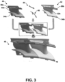
- FIG. 3 is a conceptual and schematic diagram illustrating an example first component 40 including a metal or alloy, an example second component 42 including a metal or alloy, and example PSP braze materials 44, 46 used to form an article 48.
- first component 40 includes a nozzle guide vane (NGV) for a gas turbine engine
- second component 42 includes a NGV for a gas turbine engine
- article 48 includes a doublet NGV.
- NGV nozzle guide vane
- First component 40 includes an outer platform 50a, an inner platform 54a, and an airfoil 52a that may be cast as a single, integral piece.
- second component 42 includes an outer platform 50b, an inner platform 54b, and an airfoil 52b that may be cast as a single, integral piece.
- Each of first and second components 40 and 42 may be formed of a metal or alloy, such as a Ni- or Co-based superalloy. Further, first and second components 40 and 42 may be formed of the same metal or alloy, or first component 40 may be formed of a different alloy than second component 42.
- first component 40 and second component 42 are defined by outer platforms 50a and 50b and by inner platforms 54a and 54b.
- the joints possess a more complex geometry than that shown in FIG. 1 .
- First PSP braze material 44 and second PSP braze material 46 accordingly include a more complex geometry, shaped to substantially conform to the geometry of the respective joints in which first PSP braze material 44 and second PSP braze material 46 are positioned.
- first PSP braze material 44 joins outer platforms 50a and 50b and second PSP braze material 46 joins inner platforms 54a and 54b.
- PSP braze materials 44 and 46 are used to join two simpler components, first and second components 40 and 42, to form an article 48 with a more complex geometry. This may reduce manufacturing time and cost compared to forming article 48 from a single casting.
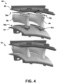
- FIG. 4 is a conceptual and schematic diagram illustrating other example components including a metal or alloy and example PSP braze materials used to form a joined article.
- first component 62 includes an outer platform of a doublet NGV for a gas turbine engine
- second component 64 includes an inner platform of the doublet NGV
- third component 66 includes a first airfoil for the doublet NGV
- fourth component 68 includes a second airfoil for the doublet NGV.
- first component 62, second component 64, third component 66, and fourth component 68 may be formed as a respective single, integral piece.
- first component 62, second component 64, third component 66, and fourth component 68 may be formed of a metal or alloy, such as a Ni- or Co-based superalloy. Further, first component 62, second component 64, third component 66, and fourth component 68 may be formed of the same metal or alloy, or at least one of first component 62, second component 64, third component 66, and fourth component 68 may be formed of a different alloy than at least one other of first component 62, second component 64, third component 66, and fourth component 68.
- First PSP braze material 70a, second PSP braze material 70b, third PSP braze material 70c, and fourth PSP braze material 70d accordingly include more complex geometries, shaped to substantially conform to the geometry of the respective joints in which first PSP braze material 70a, second PSP braze material 70b, third PSP braze material 70c, and fourth PSP braze material 70d are positioned.
- first PSP braze material 70a joins first component 62 and third component 66
- second PSP braze material 70b joins second component 64 and third component 66
- third PSP braze material 70c joins first component 62 and fourth component 68
- fourth PSP braze material 70d joins second component 64 and fourth component 68.
- PSP braze materials 70a-70d are used to a plurality of simpler components to form an article 72 with a more complex geometry. This may reduce manufacturing time and cost compared to forming article 72 from a single casting.
- FIG. 5 is a photograph illustrating example tensile test specimens including two components joined using pre-sintered preform braze materials after room temperature tensile stress testing.
- Each of the test samples were made of two portions of CMSX-3 base alloy joined by a PSP braze material.
- CMSX-3 has a composition of about 8 wt. % Cr, about 5.6 wt. % Al, about 1 wt. % Ti, about 5 wt. % Co, about 8 wt. % W, about 0.6 wt. % Mo, about 6 wt. % Ta, and about 0.1 wt. % Hf, and a balance Ni.
- the PSP braze material in this Example included a composition of about 10.2 wt.
- Each sample had an original geometry in the narrow region of about 12.7mm (0.5 inch) wide by about 4.32mm (0.170 inch) thick.
- FIG. 6 is a photograph illustrating example tensile test specimens including two components joined using pre-sintered preform braze materials after high temperature tensile stress testing.
- Each of the test samples were made of two portions of CMSX-3 base alloy joined by a PSP braze material.
- CMSX-3 has a composition of about 8 wt. % Cr, about 5.6 wt. % Al, about 1 wt. % Ti, about 5 wt. % Co, about 8 wt. % W, about 0.6 wt. % Mo, about 6 wt. % Ta, and about 0.1 wt. % Hf, and a balance Ni.
- the PSP braze material in this Example included a composition of about 10.2 wt.
- Each sample had an original geometry in the narrow region of about 12.7mm (0.5 inch) wide by about 4.32mm (0.170 inch) thick.
Landscapes
- Engineering & Computer Science (AREA)
- Mechanical Engineering (AREA)
- Chemical & Material Sciences (AREA)
- Materials Engineering (AREA)
- Metallurgy (AREA)
- Organic Chemistry (AREA)
- Composite Materials (AREA)
- Manufacturing & Machinery (AREA)
- Pressure Welding/Diffusion-Bonding (AREA)
- Powder Metallurgy (AREA)
Claims (11)
- Verfahren, umfassend:Positionieren einer ersten Komponente, die ein erstes Metall oder eine erste Legierung umfasst, und einer zweiten Komponente, die ein zweites Metall oder eine zweite Legierung umfasst, so zueinander, dass sie einen Verbindungsbereich zwischen benachbarten Abschnitten der ersten Komponente und der zweiten Komponente definieren;Positionieren eines vorgesinterten Vorform(PSP)-Hartlotmaterials in dem Verbindungsbereich, wobei das PSP-Hartlotmaterial ein Weitspalt-Hartlotmaterial umfasst;Erhitzen des PSP-Hartlotmaterials, um eine geschmolzene Hartlotlegierung zu bilden; und Abkühlen der geschmolzenen Hartlotlegierung, um die erste und die zweite Komponente zu verbinden;dadurch gekennzeichnet, dass das Weitspalt-Hartlotmaterial eines von Folgenden umfasst:zwischen 50 Gew.-% und 70 Gew.-% Ni, zwischen 10 Gew.-% und 15 Gew.-% Cr, zwischen 8 Gew.-% und 10 Gew.-% Ta, zwischen 8 Gew.-% und 10 Gew.-% Co, zwischen 4 Gew.-% und 7 Gew.-% Al, zwischen 2 Gew.-% und 4 Gew.-% W, zwischen 1 Gew.-% und 2 Gew.-% Re, 1 Gew.-% Mo, 1 Gew.-% Hf und optional jeweils bis zu 1 Gew.-% von mindestens einem von Ti, Nb, Pd, Pt, Ir, Ru, C, B, Si, P, Mn, Fe, Ce, La, Y oder Zr; oderzwischen 50 Gew.-% und 70 Gew.-% Ni, zwischen 10 Gew.-% und 15 Gew.-% Cr, zwischen 8 Gew.-% und 10 Gew.-% Ta, zwischen 8 Gew.-% und 10 Gew.-% Co, zwischen 4 Gew.-% und 7 Gew.-% Al, zwischen 2 Gew.-% und 4 Gew.-% W, zwischen 1 Gew.-% und 2 Gew.-% Re, zwischen 0,5 Gew.-% und 1 Gew.-% Mo, zwischen 0,5 Gew.-% und 1 Gew.-% Hf, zwischen 0,1 Gew.-% und 0,5 Gew.-% Nb, zwischen 0,05 Gew.-% und 3 Gew.-% Si und zwischen 0,5 Gew.-% und 2 Gew.-% B.
- Verfahren nach Anspruch 1, wobei das PSP-Hartlotmaterial 58 Gew.-% Ni, 11 Gew.-% Cr, 9 Gew.-% Ta, 9 Gew.-% Co, 5 Gew.-% Al, 3 Gew.-% W, 1 Gew.-% Mo, 1 Gew.-% Re und 1 Gew.-% Hf umfasst.
- Verfahren nach einem der Ansprüche 1 bis 2, wobei das PSP-Hartlotmaterial ferner jeweils bis zu 1 Gew. % von mindestens einem von Ti, Nb, Pd, Pt, Ir, Ru, C, P, Mn, Fe, Ce, La, Y oder Zr umfasst.
- Verfahren nach einem der Ansprüche 1 bis 3, wobei:das PSP-Hartlotmaterial eine Mischung aus einer niedrigschmelzenden Pulverzusammensetzung und einer hochschmelzenden Pulverzusammensetzung umfasst;die niedrigschmelzende Pulverzusammensetzung zwischen 50 Gew.-% und 70 Gew.-% Ni, zwischen 8 Gew.-% und 20 Gew.-% Cr, zwischen 8 Gew.-% und 15 Gew.-% Ta, zwischen 4 Gew.-% und 10 Gew.-% Co, zwischen 2 Gew.-% und 7 Gew.-% Al und bis zu 2,25 Gew.-% B umfasst; unddie hochschmelzende Pulverzusammensetzung zwischen 50 Gew.-% und 70 Gew.-% Ni, zwischen 2 Gew.-% und 10 Gew.-% Cr, zwischen 2 Gew.-% und 10 Gew.-% Ta, zwischen 5 Gew.-% und 15 Gew.-% Co, zwischen 2 Gew.-% und 10 Gew.-% Al, zwischen 2 Gew.-% und 10 Gew.-% W, bis zu 3 Gew.-% Re, bis zu 3 Gew.-% Mo und bis zu 3 Gew.-% Hf umfasst.
- Verfahren nach einem der Ansprüche 1 bis 4, wobei das Erhitzen des PSP-Hartlotmaterials, um die geschmolzene Hartlotlegierung zu bilden, Erhitzen der ersten Komponente, der zweiten Komponente und des PSP-Hartlotmaterials in einem Vakuumofen bei einer Temperatur zwischen 1093 °C und 1260 °C umfasst.
- Verfahren nach einem der Ansprüche 1 bis 5, nach dem Abkühlen der geschmolzenen Hartlotlegierung, um die erste und die zweite Komponente zu verbinden, ferner Wärmebehandeln der ersten und der zweiten Komponente unter Verwendung eines schrittweisen Diffusionszyklus durch mindestens Erhitzen der ersten und der zweiten Komponente auf 1038 °C für 1 Stunde bis 2 Stunden; Erhitzen der ersten und der zweiten Komponente auf 1093 °C für 1 Stunde bis 2 Stunden; Erhitzen der ersten und der zweiten Komponente auf 1121 °C für 1 Stunde bis 2 Stunden; Erhitzen der ersten und der zweiten Komponente auf 1149 °C für 1 Stunde bis 18 Stunden; und Abkühlen der ersten und der zweiten Komponente auf Raumtemperatur umfassend.
- Baugruppe, umfassend:eine erste Komponente, die ein erstes Metall oder eine erste Legierung umfasst;eine zweite Komponente, die ein zweites Metall oder eine zweite Legierung umfasst, wobei die erste Komponente und die zweite Komponente so benachbart zueinander positioniert sind, dass sie einen Verbindungsbereich zwischen benachbarten Abschnitten der ersten Komponente und der zweiten Komponente definieren;eine Wärmequelle zum Erhitzen des PSP-Hartlotmaterials, das in dem Verbindungsbereich angeordnet ist, um eine geschmolzene Hartlotlegierung zu bilden; undein vorgesintertes Vorform(PSP)-Hartlotmaterial, das in dem Verbindungsbereich angeordnet ist, dadurch gekennzeichnet, dass das PSP-Hartlotmaterial eines von Folgenden umfasst:zwischen 50 Gew.-% und 70 Gew.-% Ni, zwischen 10 Gew.-% und 15 Gew.-% Cr, zwischen 8 Gew.-% und 10 Gew.-% Ta, zwischen 8 Gew.-% und 10 Gew.-% Co, zwischen 4 Gew.-% und 7 Gew.-% Al, zwischen 2 Gew.-% und 4 Gew.-% W, zwischen 1 Gew.-% und 2 Gew.-% Re, 1 Gew.-% Mo, 1 Gew.-% Hf und optional jeweils bis zu 1 Gew.-% von mindestens einem von Ti, Nb, Pd, Pt, Ir, Ru, C, B, Si, P, Mn, Fe, Ce, La, Y oder Zr; oderzwischen 50 Gew.-% und 70 Gew.-% Ni, zwischen 10 Gew.-% und 15 Gew.-% Cr, zwischen 8 Gew.-% und 10 Gew.-% Ta, zwischen 8 Gew.-% und 10 Gew.-% Co, zwischen 4 Gew.-% und 7 Gew.-% Al, zwischen 2 Gew.-% und 4 Gew.-% W, zwischen 1 Gew.-% und 2 Gew.-% Re, zwischen 0,5 Gew.-% und 1 Gew.-% Mo, zwischen 0,5 Gew.-% und 1 Gew.-% Hf, zwischen 0,1 Gew.-% und 0,5 Gew.-% Nb, zwischen 0,05 Gew.-% und 3 Gew.-% Si und zwischen 0,5 Gew.-% und 2 Gew.-% B.
- Baugruppe nach Anspruch 7, wobei das PSP-Hartlotmaterial 58 Gew.-% Ni, 11 Gew.-% Cr, 9 Gew.-% Ta, 9 Gew.-% Co, 5 Gew.-% Al, 3 Gew.-% W, 1 Gew.-% Mo, 1 Gew.-% Re und 1 Gew.-% Hf umfasst.
- Baugruppe nach einem der Ansprüche 7 bis 8, wobei das PSP-Hartlotmaterial ferner jeweils bis zu 1 Gew. % von mindestens einem von Ti, Nb, Pd, Pt, Ir, Ru, C, P, Mn, Fe, Ce, La, Y oder Zr umfasst.
- Baugruppe nach einem der Ansprüche 7 bis 9, wobei:das PSP-Hartlotmaterial eine Mischung aus einer niedrigschmelzenden Pulverzusammensetzung und einer hochschmelzenden Pulverzusammensetzung umfasst;die niedrigschmelzende Pulverzusammensetzung zwischen 50 Gew.-% und 70 Gew.-% Ni, zwischen 8 Gew.-% und 20 Gew.-% Cr, zwischen 8 Gew.-% und 15 Gew.-% Ta, zwischen 4 Gew.-% und 10 Gew.-% Co, zwischen 2 Gew.-% und 7 Gew.-% Al und bis zu 2,25 Gew.-% B umfasst; unddie hochschmelzende Pulverzusammensetzung zwischen 50 Gew.-% und 70 Gew.-% Ni, zwischen 2 Gew.-% und 10 Gew.-% Cr, zwischen 2 Gew.-% und 10 Gew.-% Ta, zwischen 5 Gew.-% und 15 Gew.-% Co, zwischen 2 Gew.-% und 10 Gew.-% Al, zwischen 2 Gew.-% und 10 Gew.-% W, bis zu 3 Gew.-% Re, bis zu 3 Gew.-% Mo und bis zu 3 Gew.-% Hf umfasst.
- Baugruppe nach Anspruch 10, wobei die niedrigschmelzende Pulverzusammensetzung ferner jeweils bis zu 1 Gew. % von mindestens einem von Ti, W, Mo, Re, Nb, Hf, Pd, Pt, Ir, Ru, C, Si, P, Mn, Fe, Ce, La, Y, or Zr umfasst.
Applications Claiming Priority (1)
| Application Number | Priority Date | Filing Date | Title |
|---|---|---|---|
| US201562164285P | 2015-05-20 | 2015-05-20 |
Publications (2)
| Publication Number | Publication Date |
|---|---|
| EP3095550A1 EP3095550A1 (de) | 2016-11-23 |
| EP3095550B1 true EP3095550B1 (de) | 2025-03-19 |
Family
ID=55919730
Family Applications (1)
| Application Number | Title | Priority Date | Filing Date |
|---|---|---|---|
| EP16168659.7A Active EP3095550B1 (de) | 2015-05-20 | 2016-05-06 | Vorgesintertes vorformhartlot zum verbinden von legierungsgussstücken |
Country Status (3)
| Country | Link |
|---|---|
| US (1) | US10875128B2 (de) |
| EP (1) | EP3095550B1 (de) |
| SG (1) | SG10201603867SA (de) |
Families Citing this family (21)
| Publication number | Priority date | Publication date | Assignee | Title |
|---|---|---|---|---|
| EP3061556B1 (de) | 2015-02-26 | 2018-08-15 | Rolls-Royce Corporation | Verfahren zur reparatur von zwei dünnwandigen metallischen komponenten mithilfe von lötmaterial und hergestelltes komponent davon |
| EP3095550B1 (de) | 2015-05-20 | 2025-03-19 | Rolls-Royce Corporation | Vorgesintertes vorformhartlot zum verbinden von legierungsgussstücken |
| US9828915B2 (en) * | 2015-06-15 | 2017-11-28 | General Electric Company | Hot gas path component having near wall cooling features |
| US9970302B2 (en) | 2015-06-15 | 2018-05-15 | General Electric Company | Hot gas path component trailing edge having near wall cooling features |
| US9897006B2 (en) | 2015-06-15 | 2018-02-20 | General Electric Company | Hot gas path component cooling system having a particle collection chamber |
| US9938899B2 (en) | 2015-06-15 | 2018-04-10 | General Electric Company | Hot gas path component having cast-in features for near wall cooling |
| EP3216554B1 (de) * | 2016-03-09 | 2020-05-06 | MTU Aero Engines GmbH | Bauteil mit verschleissgeschützten öffnungen und vertiefungen sowie verfahren zur herstellung derselben |
| US11039507B2 (en) * | 2017-02-23 | 2021-06-15 | General Electric Company | Method of brazing a treatment area of a load-bearing component |
| US11338396B2 (en) | 2018-03-08 | 2022-05-24 | Rolls-Royce Corporation | Techniques and assemblies for joining components |
| CN112584956B (zh) * | 2018-08-21 | 2023-07-28 | 西门子能源美国公司 | 利用金属钎焊预烧结的预制件对涡轮翼型件进行部段替换 |
| US11090771B2 (en) | 2018-11-05 | 2021-08-17 | Rolls-Royce Corporation | Dual-walled components for a gas turbine engine |
| US11305363B2 (en) | 2019-02-11 | 2022-04-19 | Rolls-Royce Corporation | Repair of through-hole damage using braze sintered preform |
| KR102800348B1 (ko) | 2019-07-30 | 2025-04-24 | 지멘스 에너지, 인코포레이티드 | 고온 가스 터빈 블레이드들을 보수하기 위한 시스템 및 방법 |
| US11565352B2 (en) * | 2019-11-15 | 2023-01-31 | Rolls-Royce Corporation | Techniques and assemblies for joining components using solid retainer materials |
| US11999000B2 (en) * | 2020-01-03 | 2024-06-04 | Rolls-Royce Corporation | Pre-sintered preform braze reinforcement of pressure vessels |
| US11426822B2 (en) * | 2020-12-03 | 2022-08-30 | General Electric Company | Braze composition and process of using |
| US12286691B2 (en) | 2021-01-19 | 2025-04-29 | Siemens Energy, Inc. | Liquid assisted additive manufacturing of a superalloy component |
| US11692446B2 (en) | 2021-09-23 | 2023-07-04 | Rolls-Royce North American Technologies, Inc. | Airfoil with sintered powder components |
| CN113909610B (zh) * | 2021-10-27 | 2023-03-10 | 中国航发沈阳黎明航空发动机有限责任公司 | 一种第三代单晶高温合金的高性能钎焊方法 |
| CN114310028B (zh) * | 2022-01-27 | 2023-08-04 | 厦门虹鹭钨钼工业有限公司 | 一种磁控管阴极组件用钎料、钎料的制备方法、钼端帽以及磁控管 |
| EP4241906A1 (de) * | 2022-03-11 | 2023-09-13 | Siemens Aktiengesellschaft | Nickelbasislegierung, bauteil, pulver und verfahren |
Citations (4)
| Publication number | Priority date | Publication date | Assignee | Title |
|---|---|---|---|---|
| US20070163684A1 (en) * | 2006-01-18 | 2007-07-19 | Honeywell International, Inc. | Activated diffusion brazing alloys and repair process |
| US7845549B2 (en) * | 2006-05-31 | 2010-12-07 | General Electric Company | MIM braze preforms |
| US20140154082A1 (en) * | 2012-12-04 | 2014-06-05 | Brandon W. Shinn | Pre-sintered preform repair of turbine blades |
| US20140369741A1 (en) * | 2013-01-29 | 2014-12-18 | General Electric Company | Joining process and joined article |
Family Cites Families (37)
| Publication number | Priority date | Publication date | Assignee | Title |
|---|---|---|---|---|
| US3390986A (en) | 1966-08-30 | 1968-07-02 | Carrier Corp | Method of making a brazing preform |
| US4209348A (en) * | 1976-11-17 | 1980-06-24 | United Technologies Corporation | Heat treated superalloy single crystal article and process |
| FR2511908A1 (fr) | 1981-08-26 | 1983-03-04 | Snecma | Procede de brasage-diffusion destine aux pieces en superalliages |
| DE3373792D1 (en) | 1983-04-27 | 1987-10-29 | Bbc Brown Boveri & Cie | Method of joining metallic work pieces |
| EP0351948B1 (de) | 1988-07-14 | 1993-09-08 | ROLLS-ROYCE plc | Legierung und Verfahren zu ihrer Verwendung |
| US5395584A (en) * | 1992-06-17 | 1995-03-07 | Avco Corporation | Nickel-base superalloy compositions |
| US5332360A (en) | 1993-09-08 | 1994-07-26 | General Electric Company | Stator vane having reinforced braze joint |
| US5732468A (en) | 1996-12-05 | 1998-03-31 | General Electric Company | Method for bonding a turbine engine vane segment |
| US5916518A (en) | 1997-04-08 | 1999-06-29 | Allison Engine Company | Cobalt-base composition |
| US5797725A (en) | 1997-05-23 | 1998-08-25 | Allison Advanced Development Company | Gas turbine engine vane and method of manufacture |
| US6003754A (en) | 1997-10-21 | 1999-12-21 | Allison Advanced Development Co. | Airfoil for a gas turbine engine and method of manufacture |
| US6325871B1 (en) | 1997-10-27 | 2001-12-04 | Siemens Westinghouse Power Corporation | Method of bonding cast superalloys |
| US6454885B1 (en) * | 2000-12-15 | 2002-09-24 | Rolls-Royce Corporation | Nickel diffusion braze alloy and method for repair of superalloys |
| US6579061B1 (en) | 2001-07-27 | 2003-06-17 | General Electric Company | Selective step turbine nozzle |
| US20050067061A1 (en) * | 2003-09-26 | 2005-03-31 | General Electric Company | Nickel-based braze alloy compositions and related processes and articles |
| US7343676B2 (en) | 2004-01-29 | 2008-03-18 | United Technologies Corporation | Method of restoring dimensions of an airfoil and preform for performing same |
| US6951112B2 (en) | 2004-02-10 | 2005-10-04 | General Electric Company | Methods and apparatus for assembling gas turbine engines |
| US7335427B2 (en) | 2004-12-17 | 2008-02-26 | General Electric Company | Preform and method of repairing nickel-base superalloys and components repaired thereby |
| US8703044B2 (en) * | 2006-01-03 | 2014-04-22 | General Electric Company | Machine components and methods of fabricating and repairing |
| US7653994B2 (en) * | 2006-03-22 | 2010-02-02 | General Electric Company | Repair of HPT shrouds with sintered preforms |
| US8356409B2 (en) | 2007-11-01 | 2013-01-22 | United Technologies Corporation | Repair method for gas turbine engine components |
| EP2078579A1 (de) | 2008-01-10 | 2009-07-15 | Siemens Aktiengesellschaft | Verfahren zum Löten eines Bauteils und Bauteil mit Löt- und Schweissstellen |
| US8087565B2 (en) * | 2008-09-08 | 2012-01-03 | General Electric Company | Process of filling openings in a component |
| GB0913887D0 (en) | 2009-08-10 | 2009-09-16 | A method of joining components | |
| EP2353763A1 (de) | 2010-02-10 | 2011-08-10 | Siemens Aktiengesellschaft | Verfahren zur Herstellung einer Heißgaskomponente mit einem Kühlkanal beim Löten eines sinteren Teils an einen Träger ; entsprechender Heißgaskomponent |
| US8449249B2 (en) | 2010-04-09 | 2013-05-28 | Williams International Co., L.L.C. | Turbine nozzle apparatus and associated method of manufacture |
| US20120231295A1 (en) * | 2011-03-08 | 2012-09-13 | General Electric Company | Method of fabricating a component and a component |
| US10076811B2 (en) * | 2011-11-03 | 2018-09-18 | Siemens Energy, Inc. | Structural braze repair of superalloy component |
| EP2713007A1 (de) | 2012-10-01 | 2014-04-02 | Siemens Aktiengesellschaft | Reparatur von Bauteilkanten mittels PSP-Elementen und Bauteil |
| KR20150131295A (ko) * | 2013-03-15 | 2015-11-24 | 지멘스 에너지, 인코포레이티드 | 초합금 구성요소의 보수를 위한 예비 소결된 프리폼 |
| US9126279B2 (en) | 2013-09-30 | 2015-09-08 | General Electric Company | Brazing method |
| DE102014226055A1 (de) | 2014-12-16 | 2016-06-16 | Siemens Aktiengesellschaft | Verfahren zum Ausbessern einer Beschädigung an einer Turbinenschaufel |
| EP3034799B1 (de) | 2014-12-19 | 2018-02-07 | Ansaldo Energia IP UK Limited | Beschaufelung für eine Strömungsmaschine |
| US10655482B2 (en) | 2015-02-05 | 2020-05-19 | Rolls-Royce Corporation | Vane assemblies for gas turbine engines |
| EP3061556B1 (de) | 2015-02-26 | 2018-08-15 | Rolls-Royce Corporation | Verfahren zur reparatur von zwei dünnwandigen metallischen komponenten mithilfe von lötmaterial und hergestelltes komponent davon |
| EP3095550B1 (de) | 2015-05-20 | 2025-03-19 | Rolls-Royce Corporation | Vorgesintertes vorformhartlot zum verbinden von legierungsgussstücken |
| US10180250B2 (en) | 2016-07-27 | 2019-01-15 | Whirlpool Corporation | User interface for a household appliance |
-
2016
- 2016-05-06 EP EP16168659.7A patent/EP3095550B1/de active Active
- 2016-05-10 US US15/151,185 patent/US10875128B2/en active Active
- 2016-05-13 SG SG10201603867SA patent/SG10201603867SA/en unknown
Patent Citations (4)
| Publication number | Priority date | Publication date | Assignee | Title |
|---|---|---|---|---|
| US20070163684A1 (en) * | 2006-01-18 | 2007-07-19 | Honeywell International, Inc. | Activated diffusion brazing alloys and repair process |
| US7845549B2 (en) * | 2006-05-31 | 2010-12-07 | General Electric Company | MIM braze preforms |
| US20140154082A1 (en) * | 2012-12-04 | 2014-06-05 | Brandon W. Shinn | Pre-sintered preform repair of turbine blades |
| US20140369741A1 (en) * | 2013-01-29 | 2014-12-18 | General Electric Company | Joining process and joined article |
Also Published As
| Publication number | Publication date |
|---|---|
| US20160339544A1 (en) | 2016-11-24 |
| SG10201603867SA (en) | 2016-12-29 |
| US10875128B2 (en) | 2020-12-29 |
| EP3095550A1 (de) | 2016-11-23 |
Similar Documents
| Publication | Publication Date | Title |
|---|---|---|
| EP3095550B1 (de) | Vorgesintertes vorformhartlot zum verbinden von legierungsgussstücken | |
| US11731206B2 (en) | Repair of through-hole damage using braze sintered preform | |
| US11712738B2 (en) | Crack healing additive manufacturing of a superalloy component | |
| KR102228130B1 (ko) | 고 감마 프라임 니켈계 초합금 및 터빈 엔진 부품의 제조방법 | |
| US7506793B2 (en) | Preform and method of repairing nickel-base superalloys and components repaired thereby | |
| CN112760525B (zh) | 高γ′镍基超级合金、其用途及制造涡轮发动机构件的方法 | |
| US20160167172A1 (en) | Method of cladding, additive manufacturing and fusion welding of superalloys and materialf or the same | |
| US20140295087A1 (en) | Method for additively manufacturing an article made of a difficult-to-weld material | |
| CN105149597B (zh) | 金属或合金部件的修复或联结方法和经修复或联结的部件 | |
| EP2902516B1 (de) | Schweißzusatzwerkstoff für Superlegierungen auf Nickelbasis | |
| US11203064B2 (en) | Section replacement of a turbine airfoil with a metallic braze presintered preform | |
| US20090041611A1 (en) | Braze alloy composition with enhanced oxidation resistance and methods of using the same | |
| US11338396B2 (en) | Techniques and assemblies for joining components | |
| US12447545B2 (en) | Pre-sintered preform braze reinforcement of pressure vessels | |
| Miglietti | High strength, ductile wide gap braze joints for stationary turbine component repairs | |
| HK40048693B (en) | High gamma prime nickel based superalloy, its use, and method of manufacturing of turbine engine components | |
| HK40048693A (en) | High gamma prime nickel based superalloy, its use, and method of manufacturing of turbine engine components | |
| HK40050043A (en) | High gamma prime nickel based superalloy, its use, turbine components and method of manufacturing thereof | |
| HK40050043B (en) | High gamma prime nickel based superalloy, its use, turbine components and method of manufacturing thereof |
Legal Events
| Date | Code | Title | Description |
|---|---|---|---|
| PUAI | Public reference made under article 153(3) epc to a published international application that has entered the european phase |
Free format text: ORIGINAL CODE: 0009012 |
|
| AK | Designated contracting states |
Kind code of ref document: A1 Designated state(s): AL AT BE BG CH CY CZ DE DK EE ES FI FR GB GR HR HU IE IS IT LI LT LU LV MC MK MT NL NO PL PT RO RS SE SI SK SM TR |
|
| AX | Request for extension of the european patent |
Extension state: BA ME |
|
| STAA | Information on the status of an ep patent application or granted ep patent |
Free format text: STATUS: REQUEST FOR EXAMINATION WAS MADE |
|
| 17P | Request for examination filed |
Effective date: 20170512 |
|
| RBV | Designated contracting states (corrected) |
Designated state(s): AL AT BE BG CH CY CZ DE DK EE ES FI FR GB GR HR HU IE IS IT LI LT LU LV MC MK MT NL NO PL PT RO RS SE SI SK SM TR |
|
| STAA | Information on the status of an ep patent application or granted ep patent |
Free format text: STATUS: EXAMINATION IS IN PROGRESS |
|
| 17Q | First examination report despatched |
Effective date: 20190222 |
|
| GRAP | Despatch of communication of intention to grant a patent |
Free format text: ORIGINAL CODE: EPIDOSNIGR1 |
|
| STAA | Information on the status of an ep patent application or granted ep patent |
Free format text: STATUS: GRANT OF PATENT IS INTENDED |
|
| INTG | Intention to grant announced |
Effective date: 20240119 |
|
| GRAJ | Information related to disapproval of communication of intention to grant by the applicant or resumption of examination proceedings by the epo deleted |
Free format text: ORIGINAL CODE: EPIDOSDIGR1 |
|
| STAA | Information on the status of an ep patent application or granted ep patent |
Free format text: STATUS: EXAMINATION IS IN PROGRESS |
|
| INTC | Intention to grant announced (deleted) | ||
| P01 | Opt-out of the competence of the unified patent court (upc) registered |
Free format text: CASE NUMBER: APP_34789/2024 Effective date: 20240610 |
|
| GRAP | Despatch of communication of intention to grant a patent |
Free format text: ORIGINAL CODE: EPIDOSNIGR1 |
|
| STAA | Information on the status of an ep patent application or granted ep patent |
Free format text: STATUS: GRANT OF PATENT IS INTENDED |
|
| INTG | Intention to grant announced |
Effective date: 20241106 |
|
| GRAS | Grant fee paid |
Free format text: ORIGINAL CODE: EPIDOSNIGR3 |
|
| GRAA | (expected) grant |
Free format text: ORIGINAL CODE: 0009210 |
|
| STAA | Information on the status of an ep patent application or granted ep patent |
Free format text: STATUS: THE PATENT HAS BEEN GRANTED |
|
| AK | Designated contracting states |
Kind code of ref document: B1 Designated state(s): AL AT BE BG CH CY CZ DE DK EE ES FI FR GB GR HR HU IE IS IT LI LT LU LV MC MK MT NL NO PL PT RO RS SE SI SK SM TR |
|
| REG | Reference to a national code |
Ref country code: GB Ref legal event code: FG4D |
|
| REG | Reference to a national code |
Ref country code: CH Ref legal event code: EP |
|
| REG | Reference to a national code |
Ref country code: IE Ref legal event code: FG4D |
|
| REG | Reference to a national code |
Ref country code: DE Ref legal event code: R096 Ref document number: 602016091585 Country of ref document: DE |
|
| PG25 | Lapsed in a contracting state [announced via postgrant information from national office to epo] |
Ref country code: RS Free format text: LAPSE BECAUSE OF FAILURE TO SUBMIT A TRANSLATION OF THE DESCRIPTION OR TO PAY THE FEE WITHIN THE PRESCRIBED TIME-LIMIT Effective date: 20250619 |
|
| PG25 | Lapsed in a contracting state [announced via postgrant information from national office to epo] |
Ref country code: FI Free format text: LAPSE BECAUSE OF FAILURE TO SUBMIT A TRANSLATION OF THE DESCRIPTION OR TO PAY THE FEE WITHIN THE PRESCRIBED TIME-LIMIT Effective date: 20250319 |
|
| PGFP | Annual fee paid to national office [announced via postgrant information from national office to epo] |
Ref country code: DE Payment date: 20250528 Year of fee payment: 10 |
|
| REG | Reference to a national code |
Ref country code: LT Ref legal event code: MG9D |
|
| PG25 | Lapsed in a contracting state [announced via postgrant information from national office to epo] |
Ref country code: NO Free format text: LAPSE BECAUSE OF FAILURE TO SUBMIT A TRANSLATION OF THE DESCRIPTION OR TO PAY THE FEE WITHIN THE PRESCRIBED TIME-LIMIT Effective date: 20250619 |
|
| PG25 | Lapsed in a contracting state [announced via postgrant information from national office to epo] |
Ref country code: HR Free format text: LAPSE BECAUSE OF FAILURE TO SUBMIT A TRANSLATION OF THE DESCRIPTION OR TO PAY THE FEE WITHIN THE PRESCRIBED TIME-LIMIT Effective date: 20250319 |
|
| PG25 | Lapsed in a contracting state [announced via postgrant information from national office to epo] |
Ref country code: LV Free format text: LAPSE BECAUSE OF FAILURE TO SUBMIT A TRANSLATION OF THE DESCRIPTION OR TO PAY THE FEE WITHIN THE PRESCRIBED TIME-LIMIT Effective date: 20250319 |
|
| PGFP | Annual fee paid to national office [announced via postgrant information from national office to epo] |
Ref country code: FR Payment date: 20250526 Year of fee payment: 10 |
|
| PG25 | Lapsed in a contracting state [announced via postgrant information from national office to epo] |
Ref country code: GR Free format text: LAPSE BECAUSE OF FAILURE TO SUBMIT A TRANSLATION OF THE DESCRIPTION OR TO PAY THE FEE WITHIN THE PRESCRIBED TIME-LIMIT Effective date: 20250620 Ref country code: BG Free format text: LAPSE BECAUSE OF FAILURE TO SUBMIT A TRANSLATION OF THE DESCRIPTION OR TO PAY THE FEE WITHIN THE PRESCRIBED TIME-LIMIT Effective date: 20250319 |
|
| REG | Reference to a national code |
Ref country code: NL Ref legal event code: MP Effective date: 20250319 |
|
| REG | Reference to a national code |
Ref country code: AT Ref legal event code: MK05 Ref document number: 1776582 Country of ref document: AT Kind code of ref document: T Effective date: 20250319 |
|
| PG25 | Lapsed in a contracting state [announced via postgrant information from national office to epo] |
Ref country code: NL Free format text: LAPSE BECAUSE OF FAILURE TO SUBMIT A TRANSLATION OF THE DESCRIPTION OR TO PAY THE FEE WITHIN THE PRESCRIBED TIME-LIMIT Effective date: 20250319 |
|
| PG25 | Lapsed in a contracting state [announced via postgrant information from national office to epo] |
Ref country code: SE Free format text: LAPSE BECAUSE OF FAILURE TO SUBMIT A TRANSLATION OF THE DESCRIPTION OR TO PAY THE FEE WITHIN THE PRESCRIBED TIME-LIMIT Effective date: 20250319 |
|
| PG25 | Lapsed in a contracting state [announced via postgrant information from national office to epo] |
Ref country code: SM Free format text: LAPSE BECAUSE OF FAILURE TO SUBMIT A TRANSLATION OF THE DESCRIPTION OR TO PAY THE FEE WITHIN THE PRESCRIBED TIME-LIMIT Effective date: 20250319 |
|
| PG25 | Lapsed in a contracting state [announced via postgrant information from national office to epo] |
Ref country code: ES Free format text: LAPSE BECAUSE OF FAILURE TO SUBMIT A TRANSLATION OF THE DESCRIPTION OR TO PAY THE FEE WITHIN THE PRESCRIBED TIME-LIMIT Effective date: 20250319 Ref country code: PT Free format text: LAPSE BECAUSE OF FAILURE TO SUBMIT A TRANSLATION OF THE DESCRIPTION OR TO PAY THE FEE WITHIN THE PRESCRIBED TIME-LIMIT Effective date: 20250721 |
|
| PG25 | Lapsed in a contracting state [announced via postgrant information from national office to epo] |
Ref country code: PL Free format text: LAPSE BECAUSE OF FAILURE TO SUBMIT A TRANSLATION OF THE DESCRIPTION OR TO PAY THE FEE WITHIN THE PRESCRIBED TIME-LIMIT Effective date: 20250319 Ref country code: IT Free format text: LAPSE BECAUSE OF FAILURE TO SUBMIT A TRANSLATION OF THE DESCRIPTION OR TO PAY THE FEE WITHIN THE PRESCRIBED TIME-LIMIT Effective date: 20250319 |
|
| PG25 | Lapsed in a contracting state [announced via postgrant information from national office to epo] |
Ref country code: AT Free format text: LAPSE BECAUSE OF FAILURE TO SUBMIT A TRANSLATION OF THE DESCRIPTION OR TO PAY THE FEE WITHIN THE PRESCRIBED TIME-LIMIT Effective date: 20250319 |
|
| PG25 | Lapsed in a contracting state [announced via postgrant information from national office to epo] |
Ref country code: EE Free format text: LAPSE BECAUSE OF FAILURE TO SUBMIT A TRANSLATION OF THE DESCRIPTION OR TO PAY THE FEE WITHIN THE PRESCRIBED TIME-LIMIT Effective date: 20250319 Ref country code: CZ Free format text: LAPSE BECAUSE OF FAILURE TO SUBMIT A TRANSLATION OF THE DESCRIPTION OR TO PAY THE FEE WITHIN THE PRESCRIBED TIME-LIMIT Effective date: 20250319 |
|
| PG25 | Lapsed in a contracting state [announced via postgrant information from national office to epo] |
Ref country code: RO Free format text: LAPSE BECAUSE OF FAILURE TO SUBMIT A TRANSLATION OF THE DESCRIPTION OR TO PAY THE FEE WITHIN THE PRESCRIBED TIME-LIMIT Effective date: 20250319 |
|
| PG25 | Lapsed in a contracting state [announced via postgrant information from national office to epo] |
Ref country code: SK Free format text: LAPSE BECAUSE OF FAILURE TO SUBMIT A TRANSLATION OF THE DESCRIPTION OR TO PAY THE FEE WITHIN THE PRESCRIBED TIME-LIMIT Effective date: 20250319 |
|
| PG25 | Lapsed in a contracting state [announced via postgrant information from national office to epo] |
Ref country code: IS Free format text: LAPSE BECAUSE OF FAILURE TO SUBMIT A TRANSLATION OF THE DESCRIPTION OR TO PAY THE FEE WITHIN THE PRESCRIBED TIME-LIMIT Effective date: 20250719 |