EP3095499A1 - Filter device - Google Patents
Filter device Download PDFInfo
- Publication number
- EP3095499A1 EP3095499A1 EP16167079.9A EP16167079A EP3095499A1 EP 3095499 A1 EP3095499 A1 EP 3095499A1 EP 16167079 A EP16167079 A EP 16167079A EP 3095499 A1 EP3095499 A1 EP 3095499A1
- Authority
- EP
- European Patent Office
- Prior art keywords
- filter
- pressure
- pressure vessel
- filter plate
- filter device
- Prior art date
- Legal status (The legal status is an assumption and is not a legal conclusion. Google has not performed a legal analysis and makes no representation as to the accuracy of the status listed.)
- Withdrawn
Links
Images


Classifications
-
- B—PERFORMING OPERATIONS; TRANSPORTING
- B01—PHYSICAL OR CHEMICAL PROCESSES OR APPARATUS IN GENERAL
- B01D—SEPARATION
- B01D33/00—Filters with filtering elements which move during the filtering operation
- B01D33/15—Filters with filtering elements which move during the filtering operation with rotary plane filtering surfaces
- B01D33/17—Filters with filtering elements which move during the filtering operation with rotary plane filtering surfaces with rotary filtering tables
-
- B—PERFORMING OPERATIONS; TRANSPORTING
- B01—PHYSICAL OR CHEMICAL PROCESSES OR APPARATUS IN GENERAL
- B01D—SEPARATION
- B01D33/00—Filters with filtering elements which move during the filtering operation
- B01D33/58—Handling the filter cake in the filter for purposes other than for regenerating the filter cake remaining on the filtering element
- B01D33/60—Handling the filter cake in the filter for purposes other than for regenerating the filter cake remaining on the filtering element for washing
-
- B—PERFORMING OPERATIONS; TRANSPORTING
- B01—PHYSICAL OR CHEMICAL PROCESSES OR APPARATUS IN GENERAL
- B01D—SEPARATION
- B01D33/00—Filters with filtering elements which move during the filtering operation
- B01D33/58—Handling the filter cake in the filter for purposes other than for regenerating the filter cake remaining on the filtering element
- B01D33/62—Handling the filter cake in the filter for purposes other than for regenerating the filter cake remaining on the filtering element for drying
- B01D33/66—Handling the filter cake in the filter for purposes other than for regenerating the filter cake remaining on the filtering element for drying by gases or by heating
- B01D33/663—Handling the filter cake in the filter for purposes other than for regenerating the filter cake remaining on the filtering element for drying by gases or by heating by direct contact with a fluid
-
- B—PERFORMING OPERATIONS; TRANSPORTING
- B01—PHYSICAL OR CHEMICAL PROCESSES OR APPARATUS IN GENERAL
- B01D—SEPARATION
- B01D33/00—Filters with filtering elements which move during the filtering operation
- B01D33/80—Accessories
- B01D33/82—Means for pressure distribution
Definitions
- the invention relates to a filter device for separating solids from a suspension containing the solids and a suspension liquid.
- plate filters which rotate in operation about a vertical axis, so that they can fully exploit gravity.
- the cake formation and the filtration can be supported by a negative pressure applied on the back.
- pressure rotary filters In comparison with pressure rotary filters, however, the limited by the physics limitation of useful for cake formation and filtration pressure difference is disadvantageous.
- disk filters In contrast to disk filters, disk filters are arranged rotating about a horizontal axis and only partially submerge in the suspension to be filtered. They also use hydrostatic and hydrodynamic effects for cake formation and filtration. Similar to the pressure rotary filters can cake formation and Filtration also with this type of filter can not be fully supported by gravity.
- a filter device comprising a pressure vessel with a supply for pressure medium, by means of which the interior of the pressure vessel can be brought to an increased compared to the ambient pressure outside the pressure vessel pressure, at least one recorded in the pressure vessel to a substantially vertical extending rotational axis rotatably mounted filter plate, which has a plurality of filter cells, each filter cell is associated with a filter medium whose one side, the high pressure side, facing the interior of the pressure vessel, while the side facing away from the interior of the pressure vessel side, the low pressure side, with a connected to the filter plate
- Ab2020 effete is connected, in turn, via a rotary joint assembly downstream of a stationary Ab2020 Gustavssystem, a stationary Zu200 Gustavssystem for supplying suspension to be filtered and for supplying at least one treatment medium for treating the filter cake formed by the solids in the filter cells on the filter medium, and a pressure lock for discharging the solids.
- the filter device combines the advantages of pressure rotary filters and plate filters, without at the same time having their disadvantages. Due to the use of at least one filter plate on the surface of the filter cake is formed, the gravity at all points of the filter medium can be fully used for cake formation or filtration. In addition, the high pressure side of the filter medium is the interior facing the pressure vessel, so that the suspension liquid or the treatment medium is pressed with an overpressure lying above the atmospheric pressure through the filter medium. The addition of gravity and compressive force improves filtration efficiency compared to the known types of filters.
- the filter medium can be made for example of metal, plastic, textile or composite material.
- a metal filter medium may be welded to the filter cell, while a filter medium of plastic, textile or composite will advantageously be clamped to the filter cell, e.g. by means of a fastening cord, a mounting plate or the like.
- the pressure vessel may comprise a pot-shaped lower container part and a lid-like upper reservoir part.
- the pressure vessel comprises at least two pressure chambers, namely a pressure chamber arranged above the filter plate and a pressure chamber arranged below the filter plate, which are preferably in pressure equalization connection with each other, so that the pressure prevailing in the pressure vessel does not affect the filter plate only from its top side applied where it is used for filtration, but also from the bottom.
- the filter plate can be arranged pressure-balanced in the pressure vessel, which on the one hand the formation of the filter plate with a stiffening in view of the pressure forces acting on its upper side stiffening construction and on the other hand, the provision of sealing means that it at its outer edge to the pressure vessel seal off, make unnecessary.
- the lid-like upper container part is designed so that it is free of functional elements of the filter device, it can be removed, for example, for maintenance work, without a great disassembly effort from the pot-like lower container part.
- This division of the pressure vessel is also during the factory installation of the filter device of great advantage, in particular in terms of time and cost savings.
- the upper edge of the pot-like lower container part can be arranged above the filter plate in order to facilitate the supply of the feed lines for suspension to be filtered and / or treatment medium to the top of the filter plate.
- the pressure in the pressure vessel may be, for example, about 6 bar.
- the filter device has a plurality of working zones which follow one another in the circumferential direction.
- a first working zone can be designed as an application work zone.
- the suspension to be filtered fed via a first supply line of the stationary supply line system can be applied to the filter medium of the filter cell (s) currently in the application work zone.
- the pressure medium for example a gas, such as air, pushes the suspension liquid through the filter medium, so that the solids remain as filter cake on the filter medium.
- At least one treatment working zone can be provided, which can be supplied via a further supply line of the stationary feed line system at least one treatment medium for treating the solids.
- the treatment work zone or at least one of the treatment work zones can be designed as a wash zone in which applied via a feed line of the stationary feed line system washing liquid applied to the filter cake and is forced through the pressure medium through the filter cake.
- at least one of the treatment work zones may be formed as a dehumidification zone, in which the filter cake at least a portion of the existing moisture in it is withdrawn. Usually, the dehumidification takes place by displacing the moisture present in the pores of the filter cake by means of a dehumidifying medium.
- the pressure medium As a dehumidifying medium can be used, for example, the pressure medium.
- the filter cake using superheated steam, in which case not only the displacement dehumidification but also a thermal dehumidification by evaporation of the moisture present in the pores of the filter cake can play a role.
- dehumidifying in connection with the present invention does not necessarily mean the complete removal of moisture. This is also true, although the dehumidifying zone is often called “drying zone” in the general language of the art. It is essential that the filter cake in the dehumidifying zone is not left to itself, whereby it can come to a certain loss of moisture by evaporation, but that is actively acted upon for dehumidification on the filter cake.
- a discharge working zone can be provided, in which the optionally washed and / or dehumidified solids are discharged from the filter device.
- a filter medium preparation working zone may also be provided, in which the filter medium is prepared for the next filtration cycle.
- the residual layer of solids which is still on the filter medium after the discharge for example, irradiated with water and / or exposed from the back of the filter medium forth a pressure surge and thereby broken.
- clogging of the filter medium can be prevented.
- each feed line of the stationary feed line system is assigned at least one discharge line of the stationary discharge line system.
- the filter plate may have an upwardly projecting edge on its outer circumference and / or on its inner circumference. Such an edge facilitates cake formation because it prevents the suspension from flowing away, thus ensuring that the solids settle on the filter media as the slurry liquid passes through the filter media.
- the edge could also be formed on the pressure vessel or formed by the pressure vessel.
- a peripheral edge of the filter plate avoids sealing problems.
- each filter cell is assigned a separate discharge line of the circulating discharge line system, this has the advantage that the filtrates of the individual filter cells can be discharged separately from one another. Due to the interaction of the discharge lines of the circulating Ab classroom Anlagenssystems and the stationary Ab2020 Anlagenssystems via the rotary joint assembly thus supplied in a particular work zone media can also be removed via the this working zone associated discharge line of the stationary Ab2020 effetssystems.
- the working-zone-wise supply and removal of the treatment media can be further assisted by the number of filter cells being greater than the number of working zones.
- the separation of the work zones from each other can be improved. In other words, this can reduce the fraction of the medium supplied in a certain working zone, which is not dissipated via the discharge line of the stationary discharge line system assigned to this working zone.
- the filter cells are designed in such a way that the medium supplied to a filter cell in a working zone is completely immersed in this Working zone associated discharge line of the stationary Abmonirieltungssystems has been removed before the corresponding filter cell leaves the working zone or the filter cell associated discharge line of the circulating AbDOM effetes is no longer fluidly connected to the work zone associated discharge line of the stationary Abdies effetssystems.
- the working zone-wise feeding and discharging of the treatment media it is for example possible to provide a plurality of washing zones, and perform in these a multi-stage countercurrent washing of the solids.
- the circumferential angle over which each of the filter cell-associated discharge lines of the recirculating purge line system in the rotary joint assembly is smaller than the circumferential angular distance the two circumferentially successive discharge lines of the stationary one Abvant effetssystems in the rotary joint assembly from each other.
- the filter cells can be separated from each other formed elements. This allows improved ease of maintenance, since in case of need not the entire filter plate needs to be replaced, but individual filter cells can be replaced.
- the filter plate is supported at its radially outer edge on the pressure vessel.
- the diameter of a filter plate of the Filter device according to the invention may for example be between about 3.0 m and about 3.5 m.
- a support of the filter plate or the filter cells only at the radially inner edge or by using additional elements, such as diagonal supports, is basically conceivable.
- an additional support of the filter plate or the filter cells on the radially outer edge simplify the structural design of the support.
- At least one of the supply lines for supplying suspension to be filtered and / or treatment medium can be connected to an overflow unit with an overflow edge or a trickle or nozzle unit with outlet openings.
- the overflow edge or the size and the distribution of the outlet openings can be designed such that over the entire radius of the filter plate per unit time and unit area of the filter plate, the same amount of suspension or treatment medium is delivered.
- the length of a radially inner circular arc section which passes through a feed unit during a predetermined time unit is shorter than the length of a circular arc section of equal width located radially outwardly, which passes through the feed unit during the same predetermined time unit.
- the discharge amount per radial length portion and time unit in the radial direction of the filter plate must increase to the outside. This can be achieved, for example, via a recessed overflow edge, wherein the recess surfaces thereof vary over the length of the overflow unit, ie in the radial direction.
- the discharge amount can be controlled by the number or / and the diameter of the outlet openings.
- the supply line is connected adjacent to the overflow unit or the trickle or nozzle unit whose respective quantity center.
- the "volume center" of the overflow unit is understood to mean that radial position of the overflow unit, radially within which as much suspension or treatment medium is discharged onto the filter plate as radially outside. With suitable positioning of the connection of the supply line can be dispensed with elaborate distribution devices between the supply and the overflow unit or the trickle or nozzle unit.
- the sealing arrangement may, for example, comprise at least one sealing lip which is in contact with the surface of the filter cake and which, for example, rests on it, which at least hampers, if not completely prevents, a return flow of suspension liquid or treatment medium into an adjacent working zone.
- a steam hood is arranged in the pressure vessel.
- the steam in the interior of the steam hood can be present at a pressure which is substantially equal to the pressure in the remaining pressure vessel.
- the vapor remains on the one hand in the steam hood and can not be reflected on cool surface portions of the pressure vessel.
- no cool gas can penetrate from the remaining pressure vessel into the steam hood and lead there to a cooling of the steam. by virtue of of the increased pressure in the steam hood, the steam is forced through the filter cake and dehumidifies it.
- the filter cell rotates about an axis deviating from the longitudinal axis and / or is foldable in itself.
- a discharge working zone of the filter device is associated with a screw conveyor with at least one discharge screw.
- the radially outer end of the discharge screw may be disposed radially inward of the edge thereof. The discharge screw then throws the solids only over the edge from where they pass through the post-pumped solids displaced and thus can be further promoted.
- the discharge screw comprises a disposed within the outer edge of the filter plate length portion and a disposed outside the outer edge of the filter plate length portion which are connected to each other via a common, extending above the edge drive shaft. In this way, the solids thrown over the edge by the inner length section can be conveyed from the outer longitudinal section further to the discharge opening.
- the discharge screw has a conical envelope surface whose lower peripheral portion is substantially parallel to the surface of the filter plate.
- envelope surface of the discharge screw is understood to mean that surface which is formed by the outer boundary line of the conveyor screw during its rotation.
- the discharge screw may be advantageous to increase the Austrags binelles when the direction of rotation of the drive shaft of the discharge screw is selected such that the respective closest to the filter plate portion of the envelope surface of the discharge screw moves against the direction of movement of the filter plate.
- the discharge screw is associated with a lifting device which temporarily lifts it as the edge advances between two successive filter cells.
- the discharge screw is partially enveloped, in particular such that only the contact area between the discharge screw and solid layer is not enveloped.
- the discharge screw can either be mounted on one side, i. be supported only on the housing of the pressure vessel or in the vicinity of the pressure vessel housing and project freely into the pressure vessel, or be stored on both sides, i. in addition also have a storage in the interior of the pressure vessel, for example, at least one extending transversely through the pressure vessel strut or at one of the lid-like upper container part of the pressure vessel outgoing carrier.
- a motor for example an electric motor, may be provided outside the pressure vessel, which may be connected directly or via a transmission to the drive shaft of the discharge screw.
- the solids discharged from the discharge screw can be conveyed, preferably under gravity, to a section provided with the pressure lock, at which the solids can be discharged from the filter device.
- the pressure lock may comprise, for example, a rotary valve or a flap lock.
- the pressure lock can be provided at the portion where the solids are removed from the filter device to reduce the pressure loss due to the solids from the Filter device escaping gas is formed.
- the rotary valve promotes solids continuously or clocked, the flap lock only clocked.
- An inlet end and an outlet end of the pressure lock are separated from each other pressure-tight. In this way, the amount of gas exiting the pressure vessel can be reduced, which in turn has the consequence that the pressure vessel to maintain a substantially constant pressure correspondingly less gas must be supplied.
- the discharge lines of the circulating discharge line system could be guided radially outward by the filter cells. According to the invention, however, it is proposed that the discharge lines of the circulating Abdies effets are guided radially inward and extend through the interior of a fixedly connected to the filter plate, the axis of rotation substantially concentric rotor shaft, as this allows a spatially compact design of the rotary joint assembly, which has a seal arrangement between the circulating evacuation conduit system and the stationary evacuation conduit system.
- the rotary joint assembly which is also called “control head”
- control head can with a rotation axis orthogonal to the contact surface, as a so-called plan control head, or with a circumferential direction be running around the axis of rotation contact surface, designed as a so-called neck control head.
- the discharge lines of the circulating Abdies can be performed.
- the outflow of the filtrate can take place with gravity support.
- the filtrate after passing through the filter medium, can flow directly to the rotor shaft. But it can also be provided below the filter medium, a gutter and / or a collection point, via which or the filtrate can reach the filter cell associated discharge line of the circulating AbDOM effetussystems.
- At least two rotor shaft bearings can be provided.
- the rotor shaft may extend from the underside of the pressure vessel into the pressure vessel, through the filter plate, and further up to the upper vessel portion of the pressure vessel housing.
- the rotor shaft may in this case on the one hand at the point where it passes through the housing of the pressure vessel, and on the other hand at the location of the inside of the lid-like upper pressure vessel part, to which it extends, be stored.
- the rotor shaft on the one hand as in the first embodiment, be stored at the point where it passes through the housing of the pressure vessel, and on the other hand in a region adjacent to the underside of the filter plate.
- the filter plate adjacent Storage may be supported, for example, via at least one transverse web which extends through the pressure vessel.
- the rotor shaft may be supported at two locations adjacent to the filter plate above and below the filter plate. Similar to the known from the second embodiment of the filter plate adjacent storage, and the two bearings of the third embodiment may each be supported on at least one transverse web.
- a fourth embodiment of the rotor shaft bearing combination combines the above the filter plate arranged storage of the third embodiment with the known from the first and second embodiments storage at the housing passage point of the rotor shaft.
- the rotor shaft is on the one hand, as known from the first, second and fourth embodiments, mounted on the housing passage and on the other hand in a region adjacent to the top of the filter plate, wherein the rotor shaft bearing, which is arranged above the filter plate, not, as known from the third and fourth embodiments, is supported via a crosspiece, but, as known from the first embodiment, via a device which is connected to the upper container part of the pressure vessel housing.
- a sixth embodiment of the rotor bearing is substantially analogous to the second embodiment, with the difference that the bearing arranged adjacent to the underside of the filter plate does not support the rotor shaft itself, but there a corresponding attached to the filter plate portion of the rotor shaft operatively connected to the filter plate stored is.
- the second and the sixth embodiment are advantageous because both the upper container part of the Pressure housing easily disassembled and a possible impairment of the above the filter plate arranged functional elements can be avoided.
- the passage of the rotor shaft through the housing for example by means of a stuffing box, a shaft seal, a PS seal ® or a mechanical seal, be sealed.
- the rotor shaft is connected to the end of the rotor shaft opposite the filter plate with a drive unit, for example an electric motor or a hydraulic drive.
- a drive unit for example an electric motor or a hydraulic drive.
- the drive unit either directly or via an intermediate unit, such as a gear transmission, a belt drive or chain drive, be connected to the rotor shaft.
- the drive unit can also be arranged above or even inside the pressure vessel.
- the filter device according to the invention can operate completely continuously. In principle, however, it is also conceivable to operate them clocked continuously, ie to continue rotating them by a predetermined number of filter cells, for example a filter cell, in a given time cycle. Even with the clocked continuous mode of operation, a quantity of suspension introduced into a filter cell of the filter plate passes successively through the various working zones, while further quantities of suspension are supplied to other filter cells of the filter plate.
- the pulsed continuous mode of operation thus differs from the batch mode in which a predetermined amount of suspension is always subjected to all treatment steps before fresh suspension is supplied again.
- the filter device according to the invention can be operated with a plurality of filter plates arranged one above the other.
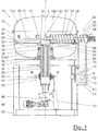
- FIG. 1 is an embodiment of the filter device according to the invention generally designated 10.
- the filter device 10 comprises a pressure housing 12, which is subdivided into a cover-like upper component 14 (hereinafter also referred to as “container cover 14") and a cup-shaped lower container part 16 (hereinafter also referred to as “container lower part 16").
- a filter medium 20 is arranged and which has an inner edge 22 and an outer edge 24.
- the outer edge 24 is the outer edge 24 on a projection 26 of the container base 16 of the pressure housing 12 supported.
- the filter plate 18 is operatively connected to a rotor shaft 28, which extends from the filter plate 18, starting in a substantially vertical direction through the container base 16 of the pressure housing 12 down through.
- a stuffing box 30 which also includes a lower bearing 32 and an upper bearing 34 for the rotor shaft 28 for rotatably supporting the rotor shaft 28.
- each filter cell 19 and its associated filter medium 20 a gap 36 is formed, which drops to a connection point 38 out.
- the intermediate space 36 is connected to a discharge line 39 of a discharge line system 40 formed by a plurality of similar discharge lines.
- each filter cell 19 is associated with a discharge line 39 of the circulating AbDOM Kochssystems 40.
- the discharge conduits 39 of the circulating discharge line system 40 which preferably have substantially identical dimensions, lead into and through the interior of the rotor shaft 28 to a rotary connection assembly 42 located outside the pressure vessel 12.
- a stationary Abgar Gustavssystems 44 arranged at the rotary union assembly 42 .
- the discharge lines 43 of the stationary Abgar Gustavssystems 44 are arranged distributed in the circumferential direction U about the rotation axis A and lead radially away from the rotary joint assembly 42. That the rotary joint assembly 42 is formed as a "shark control head".
- the rotor shaft 28 and with this the filter plate 18 is driven via an outside of the pressure vessel 12 arranged electric motor 46, which is connected in the illustrated embodiment with the rotor shaft 28 via a gear transmission 48.
- the rotor shaft 28, the rotary connection assembly 42, the electric motor 46 and the transmission 48 are supported via a support device 50, which in turn is attached to a frame 52 of the filter device 10.
- the pressure vessel 12 is supported directly and / or via intermediate elements on the frame 52.
- the filter device 10 further comprises various feed lines 84, 86, 88, 90, 92, 94 and 96 leading through the periphery of the lower container part 16 of the pressure vessel 12 into the pressure vessel 12, which will be described below with reference to FIG FIG. 2 will be described in detail, which is a top view of the filter device 10 in the direction of the arrow II in FIG. 1 with removed housing cover 14 shows.
- the region of the filter device 10 located above the filter plate 18 or the filter cells 19 can essentially be subdivided into eight work zones Z 1 to Z 8 , wherein each of the work zones is one of the feed lines 84, 86, 88, 90, 92, 94, 96 resp .,
- the discharge screw 56 is assigned.
- the stationary supply line 84 to be filtered suspension is applied to the filter medium 20 of the filter cells 19.
- the application of suspension to the filter medium 20 is likewise carried out continuously or clocked accordingly.
- the application of suspension to the filter medium 20 of the filter cell 19 is designed such that despite the substantially circular sector-shaped design of the filter cells 19 per unit time to each unit area of the present in this working zone filter cell (s) 19, the same amount of suspension is applied.
- the suspension liquid of the applied suspension is pressed by the pressure prevailing in the interior of the pressure vessel 12 through the filter medium 20, so that the solids contained in the suspension precipitate as filter cake on the filter medium 20, while the suspension liquid be derived by the circulating Abdiestechnischungssystem 40 and the stationary Abdiestechnischssystem 44.
- a treatment medium for example a washing liquid
- a treatment medium for example a washing liquid
- the feed lines 88, 90, 92 are also each used to supply treatment medium, in particular washing liquid for a second, third and fourth washing of the filter cake.
- the treatment media supplied by the stationary supply lines 86, 88, 90, 92 may be identical and / or different from each other.
- it is possible to carry out a countercurrent washing in the four working zones Z 2 to Z 5 in which the fifth working zone Z 5 is supplied with clean scrubbing liquid via the supply line 92 in order to make the filter cake already pre-scrubbed three times in the work zones Z 2 to Z 4 one last Time to wash with clean washing liquid.
- the washing liquid discharged from the fifth working zone Z 5 is then introduced via the supply line 90 into the fourth working zone Z 4 , etc., until finally the washing liquid discharged from the second working zone Z 2 or first washing zone is completely discharged from the filter device 10.
- the sixth working zone Z 6 is used for dehumidifying the filter cake. Therefore, this working zone is supplied via the stationary supply line 94, a dehumidifying medium.
- a gas is used as a dehumidifying medium and this used simultaneously as a pressurized gas. Thus, no separate compressed gas supply line needs to be provided.
- superheated steam can be used as a dehumidifying medium.
- a steam hood (not shown) open towards the filter cake into which the superheated steam is introduced.
- the pressure prevailing in the steam hood is advantageously set to a somewhat lower value than the pressure in the pressure container 12.
- the dehumidifying working zone Z 6 is followed by a discharge working zone Z 7 in which the filter cake is transported away from the filter plate 18 radially outwards by means of a discharge screw 56 to be described in detail below.
- any remaining solid residues are broken up on the filter medium 20 so that they no longer clog the filter medium 20.
- a treatment medium such as for example water
- a pressure recoil can be exerted on the filter cake from the rear side of the filter medium 20 in order to detach the filter cake from the filter medium 20.
- working zones Z 1 to Z 8 can be separated from each other by sealing arrangements (not shown), whereby it can be avoided or at least reduced that the treatment media of one working zone mix with those of another working zone.
- a discharge screw 56 is provided in the discharge zone Z 7 , which for removing the remaining after filtration on the filter medium 20 solids from the filter device 10th serves.
- the discharge screw 56 is subdivided into a longitudinal section 58 arranged within the outer edge 24 and a longitudinal section 60 arranged outside the outer edge 24. Both length sections 58 and 60 are driven via the same drive shaft 62, which in turn is driven directly or via a transmission by an electric motor 64.
- the solids resting on the filter medium 20 are conveyed radially outward from the longitudinal section 58 of the discharge screw 56 on the filter plate 18 and there via the outer edge 24 of the filter plate 18.
- the outer longitudinal section 60 of the discharge screw 56 transports the solids from there to a discharge chute 66, in which they fall down to a rotary valve 68.
- the rotary valve 68 comprises a cellular wheel 70, which has a plurality of cells 72.
- the cells 72 of the cellular wheel 70 are filled with the solids falling from above.
- the cellular wheel 70 rotates in a continuous or clocked manner about a substantially horizontal axis B.
- the cellular wheel 70 of the rotary valve 68 is driven by an electric motor 76 either directly or via a transmission.
- the electric motor 76, the rotary valve 68 and the discharge shaft 66 are connected via a holding device 78 to the frame 52.
- the discharge screw 56 is on the one hand at its point of passage through the pressure vessel 12 and on the other held on a transverse to the container base 16 of the pressure vessel 12 extending strut 80 by means of a (not shown) holder.
- the discharge screw 56 is further surrounded by a housing 82, which on the one hand prevents solids from being ejected from the discharge screw 56 and, on the other hand, provides storage for the drive shaft 62 of the discharge screw 56 at the two axial ends of the housing 82. Outside the pressure vessel 12, the housing 82 also serves to seal the pressure and hold the electric motor 64.
- FIG. 3 shows a sectional view through the rotary joint assembly 42 along the line III-III of FIG. 1 ,
- the discharge lines 39 of the circulating discharge line system 40 which extend horizontally within the rotor shaft 28 in this region, can be seen, which are open toward the outside of the rotor shaft 28.
- discharge lines 98, 102, 106, 110, 114, 118 of the stationary discharge line system 44 can be seen.
- one of the discharge lines 98, 102, 106, 110, 114, 118 of the stationary discharge line system 44 is associated with a receiving area 100, 104, 108, 112, 116, 120, which are separated from one another by sealing elements 122.
- the width of each sealing element 122 is greater than the maximum width of an opening of a discharge line of the circulating Ab classroomtechnischssystems 40 to the outside of the rotor shaft 28 out.
- the treatment medium supplied to a filter cell is fed after filtration to the filter cell 19 associated discharge line 39 of the circulating AbDOM effetes 40. Subsequently, the filtrate enters the Receiving area, with which the corresponding discharge line 39 of the circulating AbDOM effetes 40 is currently in communication, from where it is transported over the this receiving area associated discharge line of the stationary Ab gleich effetssystems 44 from the filter device 10.
- the discharge lines 98, 102, 106, 110, 114, 118 or the receiving areas 100, 104, 108, 112, 116, 120 of the discharge lines of the stationary discharge line system 44 are designed such that the respective width, i. the circumferential angle of a receiving area with the width, i. the circumferential angle, a working zone associated with the receiving area. Accordingly, in the case of a rotating filter plate 18, a discharge line 39 of the circulating discharge line system 40 communicates with a receiving region assigned to a working zone, such as the filter cell, which is associated with this discharge line 39 of the circulating discharge line system 40, is in communication with this working zone. As a result, the treatment medium supplied in the respective working zone can be removed separately from the filter device 10 after the filtration.
- the dehumidifying medium discharged from the dehumidifying working zone in the receiving region 120 is removed from the filter device 10.
- the filter plate 18 is provided with a plurality of oblique supports 54 for its stabilization. These need in the illustrated embodiment, but only the weight of the filter plate 18 together with the resting thereon filter cake and the respective treatment media to wear.
- the inner space 12a of the pressure vessel has a region 12a1 arranged above the filter plate 18 and a region 12a2 arranged below the filter plate 18 which communicate with one another via the gap between the pressure vessel 12 and the outer edge of the filter plate 18 are in pressure equalization connection.
- the same pressure prevails in both regions 12a1 and 12a2, so that the upper side and the lower side of the filter plate 18 are subjected to the same pressure and thus exert net pressure force on the filter plate 18.
Abstract
Filtervorrichtung (10) zum Abtrennen von Feststoffen aus einer Suspension, wobei die Filtervorrichtung (10) einen Druckbehälter (12) mit einer Zuführung für Druckmedium umfasst, mittels dessen der Innenraum des Druckbehälters (12) auf einen erhöhten Druck bringbar ist, wenigstens einen in dem Druckbehälter (12) aufgenommenen, um eine vertikale Rotationsachse (A) drehbar gelagerten Filterteller (18) mit einer Mehrzahl von Filterzellen, wobei jeder Filterzelle ein Filtermedium (20) zugeordnet ist, dessen Hochdruckseite dem Innenraum des Druckbehälters (12) zugewandt ist, während dessen Niederdruckseite mit einem mit dem Filterteller (18) umlaufenden Abführleitungssystem (40) verbunden ist, dem seinerseits über eine Drehverbindungsbaugruppe (42) ein stationäres Abführleitungssystem (44) nachgeordnet ist, ein stationäres Zuführleitungssystem zum Zuführen von zu filtrierender Suspension sowie zum Zuführen wenigstens eines Behandlungsmediums zum Behandeln des in den Filterzellen auf dem Filtermedium (20) von den Feststoffen gebildeten Filterkuchens, und eine Druckschleuse zum Austrag der Feststoffe.Filter device (10) for separating solids from a suspension, the filter device (10) comprising a pressure vessel (12) with a supply for pressure medium, by means of which the interior of the pressure vessel (12) can be brought to an increased pressure, at least one in the Pressure vessel (12) received, about a vertical axis of rotation (A) rotatably mounted filter plate (18) with a plurality of filter cells, each filter cell being assigned a filter medium (20), the high pressure side of which faces the interior of the pressure vessel (12), during which The low-pressure side is connected to a discharge line system (40) running around the filter plate (18), which in turn is followed by a stationary discharge line system (44) via a rotary connection assembly (42), a stationary feed line system for supplying suspension to be filtered and for supplying at least one treatment medium to the Treat the in the filter cells on the filter ermedium (20) filter cake formed by the solids, and a pressure lock for discharging the solids.
Description
Die Erfindung betrifft eine Filtervorrichtung zum Abtrennen von Feststoffen aus einer die Feststoffe und eine Suspensionsflüssigkeit enthaltenden Suspension.The invention relates to a filter device for separating solids from a suspension containing the solids and a suspension liquid.
Aus dem Stand der Technik sind zu diesem Zweck unterschiedliche Filtervorrichtungen bekannt.From the prior art different filter devices are known for this purpose.
Im Wesentlichen unterscheidet man dabei drei Hauptgruppen von Filtervorrichtungen:
- Zum einen gibt es die sogenannten Druckdrehfilter, bei denen die Filterzellen am Außenumfang einer in einem Druckbehälter aufgenommenen Trommel angeordnet sind, welche sich im Betrieb um eine horizontale Achse dreht. Ein großer Nachteil ist hierbei, dass in der unteren Umfangshälfte die Schwerkraft der Filtration bzw. der Kuchenbildung entgegen wirkt.
- On the one hand there are the so-called pressure rotary filter, in which the filter cells are arranged on the outer circumference of a drum accommodated in a pressure vessel, which rotates in operation about a horizontal axis. A major disadvantage here is that the gravity of the filtration or cake formation counteracts in the lower half of the circumference.
Des Weiteren sind sogenannte Tellerfilter bekannt, die sich im Betrieb um eine vertikale Achse drehen, so dass sie die Schwerkraft voll ausnutzen können. Zudem können die Kuchenbildung und die Filtration durch einen rückseitig angelegten Unterdruck unterstützt werden. Im Vergleich mit Druckdrehfiltern ist dabei aber die durch die Physik bedingte Begrenzung der zu Kuchenbildung und Filtration nutzbaren Druckdifferenz nachteilig.Furthermore, so-called plate filters are known, which rotate in operation about a vertical axis, so that they can fully exploit gravity. In addition, the cake formation and the filtration can be supported by a negative pressure applied on the back. In comparison with pressure rotary filters, however, the limited by the physics limitation of useful for cake formation and filtration pressure difference is disadvantageous.
Darüber hinaus gibt es noch sogenannte Scheibenfilter. Scheibenfilter sind im Unterschied zu Tellerfiltern um eine horizontale Achse drehend angeordnet und tauchen nur teilweise in die zu filtrierende Suspension ein. Ferner nutzen sie zur Kuchenbildung und Filtration hydrostatische und hydrodynamische Effekte. Analog zu den Druckdrehfiltern können Kuchenbildung und Filtration auch bei diesem Filtertyp nicht vollständig durch die Schwerkraft unterstützt werden.In addition, there are so-called disc filters. In contrast to disk filters, disk filters are arranged rotating about a horizontal axis and only partially submerge in the suspension to be filtered. They also use hydrostatic and hydrodynamic effects for cake formation and filtration. Similar to the pressure rotary filters can cake formation and Filtration also with this type of filter can not be fully supported by gravity.
Wie sich aus dieser Darstellung ergibt, weisen alle diese Arten von Filtern diverse Nachteile auf, die ihre Filtrationseffektivität einschränken.As can be seen from this illustration, all of these types of filters have several disadvantages that limit their filtration efficiency.
Es ist daher Aufgabe der vorliegenden Erfindung, eine Filtervorrichtung mit einer verbesserten Filtrationseffektivität anzugeben.It is therefore an object of the present invention to provide a filter device with improved filtration efficiency.
Diese Aufgabe wird erfindungsgemäß gelöst durch eine Filtervorrichtung, umfassend einen Druckbehälter mit einer Zuführung für Druckmedium, mittels dessen der Innenraum des Druckbehälters auf einen verglichen mit dem Umgebungsdruck außerhalb des Druckbehälters erhöhten Druck bringbar ist, wenigstens einen in dem Druckbehälter aufgenommenen, um eine im Wesentlichen vertikal verlaufende Rotationsachse drehbar gelagerten Filterteller, welcher eine Mehrzahl von Filterzellen aufweist, wobei jeder Filterzelle ein Filtermedium zugeordnet ist, dessen eine Seite, die Hochdruckseite, dem Innenraum des Druckbehälters zugewandt ist, während die vom Innenraum des Druckbehälters abgewandte Seite, die Niederdruckseite, mit einem mit dem Filterteller umlaufenden Abführleitungssystem verbunden ist, dem seinerseits über eine Drehverbindungsbaugruppe ein stationäres Abführleitungssystem nachgeordnet ist, ein stationäres Zuführleitungssystem zum Zuführen von zu filtrierender Suspension sowie zum Zuführen wenigstens eines Behandlungsmediums zum Behandeln des in den Filterzellen auf dem Filtermedium von den Feststoffen gebildeten Filterkuchens, und eine Druckschleuse zum Austrag der Feststoffe.This object is achieved by a filter device comprising a pressure vessel with a supply for pressure medium, by means of which the interior of the pressure vessel can be brought to an increased compared to the ambient pressure outside the pressure vessel pressure, at least one recorded in the pressure vessel to a substantially vertical extending rotational axis rotatably mounted filter plate, which has a plurality of filter cells, each filter cell is associated with a filter medium whose one side, the high pressure side, facing the interior of the pressure vessel, while the side facing away from the interior of the pressure vessel side, the low pressure side, with a connected to the filter plate Abführleitungssystem is connected, in turn, via a rotary joint assembly downstream of a stationary Abführleitungssystem, a stationary Zuführleitungssystem for supplying suspension to be filtered and for supplying at least one treatment medium for treating the filter cake formed by the solids in the filter cells on the filter medium, and a pressure lock for discharging the solids.
Die erfindungsgemäße Filtervorrichtung vereint die Vorteile von Druckdrehfiltern und Tellerfiltern, ohne gleichzeitig deren Nachteile aufzuweisen. Aufgrund der Verwendung wenigstens eines Filtertellers, auf dessen Oberfläche der Filterkuchen gebildet wird, kann die Schwerkraft an allen Stellen des Filtermediums voll zur Kuchenbildung bzw. zur Filtration genutzt werden. Darüber hinaus ist die Hochdruckseite des Filtermediums dem Innenraum des Druckbehälters zugewandt, so dass die Suspensionsflüssigkeit bzw. das Behandlungsmedium mit einem über dem Atmosphärendruck liegenden Überdruck durch das Filtermedium gepressf wird. Die Addition von Schwerkraft und Druckkraft verbessern die Filtrationseffektivität verglichen mit den bekannten Arten von Filtern.The filter device according to the invention combines the advantages of pressure rotary filters and plate filters, without at the same time having their disadvantages. Due to the use of at least one filter plate on the surface of the filter cake is formed, the gravity at all points of the filter medium can be fully used for cake formation or filtration. In addition, the high pressure side of the filter medium is the interior facing the pressure vessel, so that the suspension liquid or the treatment medium is pressed with an overpressure lying above the atmospheric pressure through the filter medium. The addition of gravity and compressive force improves filtration efficiency compared to the known types of filters.
Das Filtermedium kann beispielsweise aus Metall, Kunststoff, Textil oder Verbundwerkstoff hergestellt sein. Dabei kann ein metallenes Filtermedium an der Filterzelle beispielsweise festgeschweißt sein, während ein Filtermedium aus Kunststoff, Textil oder Verbundwerkstoff vorteilhafterweise an der Filterzelle festgeklemmt sein wird, z.B. mittels einer Befestigungskordel, eines Befestigungsblechs oder dergleichen.The filter medium can be made for example of metal, plastic, textile or composite material. For example, a metal filter medium may be welded to the filter cell, while a filter medium of plastic, textile or composite will advantageously be clamped to the filter cell, e.g. by means of a fastening cord, a mounting plate or the like.
In Weiterbildung der Erfindung kann der Druckbehälter ein topfartig ausgebildetes unteres Behälterteil und ein deckelartig ausgebildetes oberes Behälterteil umfassen. Hierdurch kann erreicht werden, dass der Druckbehälter wenigstens zwei Druckräume umfasst, nämlich einen oberhalb des Filtertellers angeordneten Druckraum und einen unterhalb des Filtertellers angeordneten Druckraum, welche vorzugsweise miteinander in Druckausgleichsverbindung stehen, so dass der im Druckbehälter herrschende Druck den Filterteller nicht nur von dessen Oberseite her beaufschlagt, wo er zur Filtration genutzt wird, sondern auch von dessen Unterseite her. Somit kann der Filterteller in dem Druckbehälter druckausgeglichen angeordnet werden, was zum einen die Ausbildung des Filtertellers mit einer diesen im Hinblick auf die von seiner Oberseite her auf ihn einwirkenden Druckkräfte versteifenden Konstruktion und zum anderen das Vorsehen von Dichtungsmitteln, die ihn an seinem Außenrand zum Druckbehälter hin abdichten, entbehrlich macht.In a development of the invention, the pressure vessel may comprise a pot-shaped lower container part and a lid-like upper reservoir part. In this way, it can be achieved that the pressure vessel comprises at least two pressure chambers, namely a pressure chamber arranged above the filter plate and a pressure chamber arranged below the filter plate, which are preferably in pressure equalization connection with each other, so that the pressure prevailing in the pressure vessel does not affect the filter plate only from its top side applied where it is used for filtration, but also from the bottom. Thus, the filter plate can be arranged pressure-balanced in the pressure vessel, which on the one hand the formation of the filter plate with a stiffening in view of the pressure forces acting on its upper side stiffening construction and on the other hand, the provision of sealing means that it at its outer edge to the pressure vessel seal off, make unnecessary.
Ist dabei das deckelartige obere Behälterteil frei von Funktionselementen der Filtervorrichtung ausgelegt, so kann es, beispielsweise für Wartungsarbeiten, ohne großen Demontageaufwand von dem topfartigen unteren Behälterteil abgenommen werden. Diese Aufteilung des Druckbehälters ist auch während der werkseitigen Montage der Filtervorrichtung von großem Vorteil, insbesondere im Hinblick auf Zeit- und Kosteneinsparungsmöglichkeiten. Vorteilhafterweise kann der obere Rand des topfartigen unteren Behälterteils oberhalb des Filtertellers angeordnet sein, um die Zuführung der Zuführleitungen für zu filtrierende Suspension und/oder Behandlungsmedium zur Oberseite des Filtertellers zu erleichtern.If the lid-like upper container part is designed so that it is free of functional elements of the filter device, it can be removed, for example, for maintenance work, without a great disassembly effort from the pot-like lower container part. This division of the pressure vessel is also during the factory installation of the filter device of great advantage, in particular in terms of time and cost savings. Advantageously, the upper edge of the pot-like lower container part can be arranged above the filter plate in order to facilitate the supply of the feed lines for suspension to be filtered and / or treatment medium to the top of the filter plate.
Der Druck in dem Druckbehälter kann beispielsweise in etwa 6 bar betragen.The pressure in the pressure vessel may be, for example, about 6 bar.
Wie dies sowohl von Druckdrehfiltern als auch von Tellerfiltern an sich bekannt ist, kann auch bei der erfindungsgemäßen Filtervorrichtung vorgesehen sein, dass die Filtervorrichtung eine Mehrzahl von in Umfangsrichtung aufeinander folgenden Arbeitszonen aufweist.As is known per se both from pressure rotary filters and from disk filters, it can also be provided in the case of the filter device according to the invention that the filter device has a plurality of working zones which follow one another in the circumferential direction.
So kann beispielsweise eine erste Arbeitszone als Aufbringungs-Arbeitszone ausgebildet sein. In dieser Aufbringungs-Arbeitszone kann die über eine erste Zuführleitung des stationären Zuführleitungssystems zugeführte, zu filtrierende Suspension auf das Filtermedium der sich gerade in der Aufbringungs-Arbeitszone aufhaltenden Filterzelle(n) aufgebracht werden. Das Druckmedium, beispielsweise ein Gas, etwa Luft, drückt die Suspensionsflüssigkeit durch das Filtermedium, so dass die Feststoffe als Filterkuchen auf dem Filtermedium zurückbleiben.For example, a first working zone can be designed as an application work zone. In this application work zone, the suspension to be filtered fed via a first supply line of the stationary supply line system can be applied to the filter medium of the filter cell (s) currently in the application work zone. The pressure medium, for example a gas, such as air, pushes the suspension liquid through the filter medium, so that the solids remain as filter cake on the filter medium.
Ferner kann wenigstens eine Behandlungs-Arbeitszone vorgesehen sein, der über eine weitere Zuführleitung des stationären Zuführleitungssystems wenigstens ein Behandlungsmedium zum Behandeln der Feststoffe zugeführt werden kann. Die Behandlungs-Arbeitszone bzw. wenigstens eine der Behandlungs-Arbeitszonen kann dabei als Waschzone ausgebildet sein, in welcher über eine Zuführleitung des stationären Zuführleitungssystems zugeführte Waschflüssigkeit auf den Filterkuchen aufgebracht und durch das Druckmedium durch den Filterkuchen hindurchgedrückt wird. Darüber hinaus kann wenigstens eine der Behandlungs-Arbeitszonen als Entfeuchtungszone ausgebildet sein, in der dem Filterkuchen zumindest ein Teil der in ihm vorhandenen Feuchtigkeit entzogen wird. Üblicherweise erfolgt die Entfeuchtung durch Verdrängung der in den Poren des Filterkuchens vorhandenen Feuchtigkeit mittels eines Entfeuchtungsmediums. Als Entfeuchtungsmedium kann dabei beispielsweise das Druckmedium verwendet werden. Es ist aber auch möglich, den Filterkuchen unter Verwendung von überhitztem Dampf zu entfeuchten, wobei in diesem Fall neben der Verdrängungsentfeuchtung auch eine thermische Entfeuchtung durch Verdampfen der in den Poren des Filterkuchens vorhandenen Feuchtigkeit eine Rolle spielen kann. Schließlich ist es auch noch denkbar, den Filterkuchen durch mechanisches Komprimieren zu entfeuchten.Furthermore, at least one treatment working zone can be provided, which can be supplied via a further supply line of the stationary feed line system at least one treatment medium for treating the solids. The treatment work zone or at least one of the treatment work zones can be designed as a wash zone in which applied via a feed line of the stationary feed line system washing liquid applied to the filter cake and is forced through the pressure medium through the filter cake. In addition, at least one of the treatment work zones may be formed as a dehumidification zone, in which the filter cake at least a portion of the existing moisture in it is withdrawn. Usually, the dehumidification takes place by displacing the moisture present in the pores of the filter cake by means of a dehumidifying medium. As a dehumidifying medium can be used, for example, the pressure medium. However, it is also possible to dehumidify the filter cake using superheated steam, in which case not only the displacement dehumidification but also a thermal dehumidification by evaporation of the moisture present in the pores of the filter cake can play a role. Finally, it is also conceivable to dehumidify the filter cake by mechanical compression.
An dieser Stelle sei darauf verwiesen, dass unter "Entfeuchten" im Zusammenhang mit der vorliegenden Erfindung nicht notwendigerweise der vollständige Entzug von Feuchtigkeit verstanden wird. Dies trifft auch zu, obgleich die Entfeuchtungszone im allgemeinen Sprachgebrauch der Fachleute häufig "Trocknungszone" genannt wird. Wesentlich ist, dass der Filterkuchen in der Entfeuchtungszone nicht sich selbst überlassen wird, wobei es zu einem gewissen Feuchtigkeitsverlust durch Verdampfen kommen kann, sondern dass zum Entfeuchten aktiv auf den Filterkuchen eingewirkt wird.It should be noted at this point that "dehumidifying" in connection with the present invention does not necessarily mean the complete removal of moisture. This is also true, although the dehumidifying zone is often called "drying zone" in the general language of the art. It is essential that the filter cake in the dehumidifying zone is not left to itself, whereby it can come to a certain loss of moisture by evaporation, but that is actively acted upon for dehumidification on the filter cake.
Des Weiteren kann eine Austrags-Arbeitszone vorgesehen sein, in welcher die gewünschtenfalls gewaschenen und/oder entfeuchteten Feststoffe aus der Filtervorrichtung ausgetragen werden.Furthermore, a discharge working zone can be provided, in which the optionally washed and / or dehumidified solids are discharged from the filter device.
Schließlich kann auch noch eine Filtermediumvorbereitungs-Arbeitszone vorgesehen sein, in der das Filtermedium auf den nächsten Filtrierzyklus vorbereitet wird. So kann in dieser Filtermediumvorbereitungs-Arbeitszone die Restschicht von Feststoffen, die sich nach dem Austrag noch auf dem Filtermedium befindet, beispielsweise mit Wasser bestrahlt und/oder von der Rückseite des Filtermediums her einem Druckstoß ausgesetzt und dadurch aufgebrochen werden. Hierdurch kann einem Zusetzen des Filtermediums vorgebeugt werden.Finally, a filter medium preparation working zone may also be provided, in which the filter medium is prepared for the next filtration cycle. Thus, in this filter medium preparation work zone, the residual layer of solids which is still on the filter medium after the discharge, for example, irradiated with water and / or exposed from the back of the filter medium forth a pressure surge and thereby broken. As a result, clogging of the filter medium can be prevented.
Zur Verwirklichung der Ausbildung der Filtervorrichtung mit einer Mehrzahl von in Umfangsrichtung aufeinander folgenden Arbeitszonen ist es ferner vorteilhaft, wenn jeder Zuführleitung des stationären Zuführleitungssystems wenigstens eine Abführleitung des stationären Abführleitungssystems zugeordnet ist.In order to realize the design of the filter device with a plurality of work zones which follow one another in the circumferential direction, it is further advantageous if each feed line of the stationary feed line system is assigned at least one discharge line of the stationary discharge line system.
In Weiterbildung der Erfindung kann der Filterteller an seinem Außenumfang oder/und an seinem Innenumfang einen nach oben abstehenden Rand aufweisen. Ein derartiger Rand vereinfacht die Kuchenbildung, da er das Wegfließen der Suspension verhindert und somit sicherstellt, dass sich die Feststoffe auf dem Filtermedium ablagern, während die Suspensionsflüssigkeit durch das Filtermedium hindurchtritt. Grundsätzlich könnte der Rand auch am Druckbehälter ausgebildet bzw. vom Druckbehälter gebildet sein. Ein mit dem Filterteller umlaufender Rand vermeidet jedoch Dichtungsprobleme.In a further development of the invention, the filter plate may have an upwardly projecting edge on its outer circumference and / or on its inner circumference. Such an edge facilitates cake formation because it prevents the suspension from flowing away, thus ensuring that the solids settle on the filter media as the slurry liquid passes through the filter media. In principle, the edge could also be formed on the pressure vessel or formed by the pressure vessel. However, a peripheral edge of the filter plate avoids sealing problems.
Wenn jeder Filterzelle eine gesonderte Abführleitung des umlaufenden Abführleitungssystems zugeordnet ist, so hat dies den Vorteil, dass die Filtrate der einzelnen Filterzellen voneinander getrennt abgeführt werden können. Aufgrund des Zusammenwirkens der Abführleitungen des umlaufenden Abführleitungssystems und des stationären Abführleitungssystems über die Drehverbindungsbaugruppe können somit die in einer bestimmten Arbeitszone zugeführten Medien auch über die dieser Arbeitszone zugeordnete Abführleitung des stationären Abführleitungssystems abgeführt werden.If each filter cell is assigned a separate discharge line of the circulating discharge line system, this has the advantage that the filtrates of the individual filter cells can be discharged separately from one another. Due to the interaction of the discharge lines of the circulating Abführleitungssystems and the stationary Abführleitungssystems via the rotary joint assembly thus supplied in a particular work zone media can also be removed via the this working zone associated discharge line of the stationary Abführleitungssystems.
Das arbeitszonenweise Zuführen und Abführen der Behandlungsmedien kann weiter dadurch unterstützt werden, dass die Anzahl der Filterzellen größer ist als die Anzahl derArbeitszonen. Hierdurch kann die Trennung der Arbeitszonen voneinander verbessert werden. Mit anderen Worten kann hierdurch der Bruchteil des in einer bestimmten Arbeitszone zugeführten Mediums verringert werden, der nicht über die dieser Arbeitszone zugeordnete Abführleitung des stationären Abführleitungssystems abgeführt wird. Vorteilhafterweise sind die Filterzellen derart ausgelegt, dass das einer Filterzelle in einer Arbeitszone zugeführte Medium vollständig in die dieser Arbeitszone zugeordnete Abführleitung des stationären Abführieltungssystems abgeführt worden ist, bevor die entsprechende Filterzelle die Arbeitszone verlässt bzw. die der Filterzelle zugeordnete Abführleitung des umlaufenden Abführleitungssystems nicht mehr mit der der Arbeitszone zugeordneten Abführleitung des stationären Abführleitungssystems fluidleitungsmäßig in Verbindung steht.The working-zone-wise supply and removal of the treatment media can be further assisted by the number of filter cells being greater than the number of working zones. As a result, the separation of the work zones from each other can be improved. In other words, this can reduce the fraction of the medium supplied in a certain working zone, which is not dissipated via the discharge line of the stationary discharge line system assigned to this working zone. Advantageously, the filter cells are designed in such a way that the medium supplied to a filter cell in a working zone is completely immersed in this Working zone associated discharge line of the stationary Abführieltungssystems has been removed before the corresponding filter cell leaves the working zone or the filter cell associated discharge line of the circulating Abführleitungssystems is no longer fluidly connected to the work zone associated discharge line of the stationary Abführleitungssystems.
Durch das arbeitszonenweise Zuführen und Abführen der Behandlungsmedien ist es beispielsweise möglich, eine Mehrzahl von Waschzonen vorzusehen, und in diesen eine mehrstufige Gegenstromwaschung der Feststoffe durchzuführen.By the working zone-wise feeding and discharging of the treatment media, it is for example possible to provide a plurality of washing zones, and perform in these a multi-stage countercurrent washing of the solids.
Zur Ermöglichung des arbeitszonenweisen Zuführens und Abführens der Behandlungsmedien kann ferner vorgesehen sein, dass der Umfangswinkel, über den sich jede der den Filterzellen zugeordneten Abführleitungen des umlaufenden Abführleitungssystems in der Drehverbindungsbaugruppe erstreckt, kleiner ist als der Umfangswinkelabstand, den zwei in Umfangsrichtung aufeinander folgende Abführleitungen des stationären Abführleitungssystems in der Drehverbindungsbaugruppe voneinander aufweisen. Somit können die Arbeitszonen behandlungsmedium-technisch im Wesentlichen vollständig voneinander getrennt werden. Dadurch kann sichergestellt werden, dass zu keinem Zeitpunkt des Umlaufs des Filtertellers eine Abführleitung des umlaufenden Abführleitungssystems mit mehr als einer Abführleitung des stationären Abführleitungssystems in Verbindung steht.In addition, to allow work zone-wise supply and discharge of the treatment media, the circumferential angle over which each of the filter cell-associated discharge lines of the recirculating purge line system in the rotary joint assembly is smaller than the circumferential angular distance the two circumferentially successive discharge lines of the stationary one Abführleitungssystems in the rotary joint assembly from each other. Thus, the working zones treatment technology can be essentially completely separated from each other. This can ensure that at no time during the circulation of the filter plate, a discharge line of the circulating Abführleitungssystems is more than one discharge line of the stationary Abführleitungssystems in connection.
In Weiterbildung der Erfindung können die Filterzellen voneinander getrennt ausgebildete Elemente sein. Dies ermöglicht eine verbesserte Wartungsfreundlichkeit, da im Bedarfsfall nicht der gesamte Filterteller ausgetauscht zu werden braucht, sondern einzelne Filterzellen ausgetauscht werden können.In a further development of the invention, the filter cells can be separated from each other formed elements. This allows improved ease of maintenance, since in case of need not the entire filter plate needs to be replaced, but individual filter cells can be replaced.
Ferner ist es denkbar, dass der Filterteller an seinem radial äußeren Rand an dem Druckbehälter abgestützt ist. Der Durchmesser eines Filtertellers der erfindungsgemäßen Filtervorrichtung kann beispielsweise zwischen etwa 3,0 m und etwa 3,5 m betragen. Eine Abstützung des Filtertellers bzw. der Filterzellen nur an deren radial inneren Rand oder unter Verwendung von Zusatzelementen, beispielsweise Schrägstützen, ist grundsätzlich denkbar. Jedoch kann eine zusätzliche Abstützung des Filtertellers bzw. der Filterzellen am radial äußeren Rand die konstruktive Ausgestaltung der Abstützung vereinfachen.Furthermore, it is conceivable that the filter plate is supported at its radially outer edge on the pressure vessel. The diameter of a filter plate of the Filter device according to the invention may for example be between about 3.0 m and about 3.5 m. A support of the filter plate or the filter cells only at the radially inner edge or by using additional elements, such as diagonal supports, is basically conceivable. However, an additional support of the filter plate or the filter cells on the radially outer edge simplify the structural design of the support.
In Weiterbildung der Erfindung kann wenigstens eine der Zuführleitungen zum Zuführen von zu filtrierender Suspension und/oder Behandlungsmedium an eine Überlaufeinheit mit einer Überlaufkante oder eine Riesel- oder Düseneinheit mit Austrittsöffnungen angeschlossen sein. Dabei kann die Überlaufkante bzw. die Größe und die Verteilung der Austrittsöffnungen derart gestaltet sein, dass über den gesamten Radius des Filtertellers pro Zeiteinheit und Flächeneinheit des Filtertellers die gleiche Menge an Suspension bzw. Behandlungsmedium abgegeben wird. Bei einer im Wesentlichen kreisscheibenförmigen Ausgestaltung des Filtertellers ist die Länge eines radial innen gelegenen Kreisbogenabschnitts, welcher während einer vorbestimmten Zeiteinheit eine Zuführeinheit passiert, kürzer als die Länge eines radial weiter außen gelegen Kreisbogenabschnitts gleicher Breite, welcher während derselben vorbestimmten Zeiteinheit die Zuführeinheit passiert. Um zu erreichen, dass über den gesamten Radius des Filtertellers pro Zeiteinheit und Flächeneinheit des Filtertellers die gleiche Menge an Suspension oder Behandlungsmedium abgegeben wird, muss dementsprechend die Abgabemenge pro radialem Längenabschnitt und Zeiteinheit in radialer Richtung des Filtertellers nach außen hin ansteigen. Dies kann beispielsweise über eine mit Aussparungen versehene Überlaufkante erreicht werden, wobei deren Aussparungsflächen über die Länge der Überlaufeinheit, d.h. in radialer Richtung, variieren. Im Falle einer Rieseleinheit kann die Abgabemenge über die Anzahl oder/und den Durchmesser der Austrittsöffnungen gesteuert werden.In a further development of the invention, at least one of the supply lines for supplying suspension to be filtered and / or treatment medium can be connected to an overflow unit with an overflow edge or a trickle or nozzle unit with outlet openings. In this case, the overflow edge or the size and the distribution of the outlet openings can be designed such that over the entire radius of the filter plate per unit time and unit area of the filter plate, the same amount of suspension or treatment medium is delivered. In a substantially circular disk-shaped configuration of the filter plate, the length of a radially inner circular arc section which passes through a feed unit during a predetermined time unit is shorter than the length of a circular arc section of equal width located radially outwardly, which passes through the feed unit during the same predetermined time unit. In order to achieve that over the entire radius of the filter plate per unit time and unit area of the filter plate, the same amount of suspension or treatment medium is discharged, accordingly, the discharge amount per radial length portion and time unit in the radial direction of the filter plate must increase to the outside. This can be achieved, for example, via a recessed overflow edge, wherein the recess surfaces thereof vary over the length of the overflow unit, ie in the radial direction. In the case of a trickle unit, the discharge amount can be controlled by the number or / and the diameter of the outlet openings.
Dies gilt in analoger Weise auch für nicht-kreisscheibenförmige Filterteller, beispielsweise Filterteller mit mehreckigem Umfang, bei welchen die Filterzellen z.B. trapezförmig ausgebildet sein können.This also applies analogously to non-circular disk-shaped filter plates, for example filter plates with a polygonal circumference, in which the filter cells are e.g. Trapezoidal may be formed.
In Weiterbildung der Erfindung kann vorgesehen sein, dass die Zuführleitung an die Überlaufeinheit oder die Riesel- oder Düseneinheit deren jeweiliger Mengenmitte benachbart angeschlossen ist. Unter der "Mengenmitte" der Überlaufeinheit wird dabei jene Radialposition der Überlaufeinheit verstanden, radial innerhalb derer genauso viel Suspension bzw. Behandlungsmedium auf den Filterteller abgegeben wird wie radial außerhalb. Bei geeigneter Positionierung des Anschlusses der Zuführleitung kann auf aufwändige Verteilervorrichtungen zwischen der Zuführleitung und der Überlaufeinheit oder der Riesel- oder Düseneinheit verzichtet werden.In a further development of the invention it can be provided that the supply line is connected adjacent to the overflow unit or the trickle or nozzle unit whose respective quantity center. The "volume center" of the overflow unit is understood to mean that radial position of the overflow unit, radially within which as much suspension or treatment medium is discharged onto the filter plate as radially outside. With suitable positioning of the connection of the supply line can be dispensed with elaborate distribution devices between the supply and the overflow unit or the trickle or nozzle unit.
Um einen Übertritt von Suspension bzw. Behandlungsmedium von einer Arbeitszone zu einer anderen verhindern zu können, wird vorgeschlagen, dass wenigstens zwei in Umfangsrichtung aufeinander folgende Arbeitszonen mittels einer Dichtungsanordnung voneinander getrennt sind. Die Dichtungsanordnung kann beispielsweise wenigstens eine mit der Oberfläche des Filterkuchens in Kontakt stehende, beispielsweise auf dieser aufliegende, Dichtungslippe umfassen, welche einen Rückfluss von Suspensionsflüssigkeit bzw. Behandlungsmedium in eine benachbarte Arbeitszone zumindest behindert, wenn nicht gar vollständig verhindert.In order to be able to prevent a transfer of suspension or treatment medium from one working zone to another, it is proposed that at least two work zones which follow one another in the circumferential direction are separated from one another by means of a sealing arrangement. The sealing arrangement may, for example, comprise at least one sealing lip which is in contact with the surface of the filter cake and which, for example, rests on it, which at least hampers, if not completely prevents, a return flow of suspension liquid or treatment medium into an adjacent working zone.
Für den Fall, dass der Filterkuchen in der Entfeuchtungszone mittels Dampf entfeuchtet werden soll, wird vorgeschlagen, dass in dem Druckbehälter eine Dampfhaube angeordnet ist. Vorteilhafterweise kann der Dampf im Innenraum der Dampfhaube mit einem Druck vorliegen, der im Wesentlichen gleich dem Druck im restlichen Druckbehälter ist. Auf diese Weise verbleibt der Dampf einerseits in der Dampfhaube und kann sich nicht an kühlen Oberflächenabschnitten des Druckbehälters niederschlagen. Andererseits kann auch kein kühles Gas aus dem restlichen Druckbehälter in die Dampfhaube eindringen und dort zu einer Abkühlung des Dampfes führen. Aufgrund des erhöhten Drucks in der Dampfhaube wird der Dampf durch den Filterkuchen gedrückt und entfeuchtet diesen.In the event that the filter cake is to be dehumidified in the dehumidifying zone by means of steam, it is proposed that a steam hood is arranged in the pressure vessel. Advantageously, the steam in the interior of the steam hood can be present at a pressure which is substantially equal to the pressure in the remaining pressure vessel. In this way, the vapor remains on the one hand in the steam hood and can not be reflected on cool surface portions of the pressure vessel. On the other hand, no cool gas can penetrate from the remaining pressure vessel into the steam hood and lead there to a cooling of the steam. by virtue of of the increased pressure in the steam hood, the steam is forced through the filter cake and dehumidifies it.
Es versteht sich, dass im Falle des nachstehend noch ausführlicher beschriebenen Feucht- bzw. Nassaustrags der Feststoffe auf deren vorangehende Entfeuchtung verzichtet werden kann.It is understood that in the case of the wet or wet discharge of the solids described in more detail below, their previous dehumidification can be dispensed with.
Für den Austrag der Feststoffe wurde im Stand der Technik bereits eine Vielzahl von Lösungen vorgeschlagen. Bei einem passiv in seinerArbeitsstellung verharrenden Filterteller bzw. passiv in ihrer Arbeitsstellung verharrenden Filterzellen können die Feststoffe beispielsweise mittels eines Schneckenförderers, eines Schabers, eines Kratzers, beispielsweise eines Kettenkratzers, oder dergleichen ausgetragen werden. Es sind aber auch Austragsvarianten bekannt, bei welchen die Filterzellen des Filtertellers aktiv um ihre radial zur Rotationsachse verlaufende Längsachse gedreht bzw. gekippt werden, um die Feststoffe, gegebenenfalls unterstützt durch einen Druckrückstoß, aktiv abzuwerfen. So können die Feststoffe bei einer Drehung der Filterzelle um zwischen 90° und 180° schwerkraftbedingt in einen Bereich unterhalb des Filtertellers abgeworfen werden.For the discharge of solids, a large number of solutions have already been proposed in the prior art. In the case of a filter plate which remains passive in its working position or filter cells which passively remain in their working position, the solids can be discharged, for example, by means of a screw conveyor, a scraper, a scraper, for example a chain scraper, or the like. But there are also Austragsvarianten known in which the filter cells of the filter plate are actively rotated or tilted about their axis extending radially to the axis of rotation longitudinal axis or tilted to actively throw off the solids, optionally supported by a pressure recoil. Thus, the solids can be dropped by a rotation of the filter cell by between 90 ° and 180 ° due to gravity in an area below the filter plate.
Denkbar ist auch, dass sich die Filterzelle um eine von der Längsachse abweichende Achse dreht oder/und in sich faltbar ist.It is also conceivable that the filter cell rotates about an axis deviating from the longitudinal axis and / or is foldable in itself.
Aufgrund der insgesamt einfacheren Konstruktion der Filtervorrichtung und ihres robusten Aufbaus wegen wird erfindungsgemäß vorgeschlagen, dass einer Austrags-Arbeitszone der Filtervorrichtung ein Schneckenförderer mit wenigstens einer Austragsschnecke zugeordnet ist.Due to the overall simpler design of the filter device and its robust structure because of the invention, it is proposed that a discharge working zone of the filter device is associated with a screw conveyor with at least one discharge screw.
Falls der Filterteller mit einem radial äußeren, nach oben abstehenden Rand ausgebildet ist, kann das radial äußere Ende der Austragsschnecke radial innerhalb des Rands diesem benachbart angeordnet sein. Die Austragsschnecke wirft die Feststoffe dann lediglich über den Rand, von wo sie durch die nachgeförderten Feststoffe verdrängt und dadurch weitergefördert werden können.If the filter plate is formed with a radially outer upstanding edge, the radially outer end of the discharge screw may be disposed radially inward of the edge thereof. The discharge screw then throws the solids only over the edge from where they pass through the post-pumped solids displaced and thus can be further promoted.
Es ist jedoch auch denkbar, dass die Austragsschnecke einen innerhalb des äußeren Rands des Filtertellers angeordneten Längenabschnitt und einen außerhalb des äußeren Rands des Filtertellers angeordneten Längenabschnitt umfasst, die über eine gemeinsame, oberhalb des Rands verlaufende Antriebswelle miteinander verbunden sind. Auf diese Weise können die vom inneren Längenabschnitt über den Rand geworfenen Feststoffe vom äußeren Längenabschnitt weiter zur Austragsöffnung gefördert werden.However, it is also conceivable that the discharge screw comprises a disposed within the outer edge of the filter plate length portion and a disposed outside the outer edge of the filter plate length portion which are connected to each other via a common, extending above the edge drive shaft. In this way, the solids thrown over the edge by the inner length section can be conveyed from the outer longitudinal section further to the discharge opening.
Zur Vermeidung der Aufteilung der Austragsschnecke in eine Mehrzahl von Abschnitten ist es ferner denkbar, den äußeren Rand des Filtertellers im Bereich der Austragsschnecke absenkbar auszubilden, beispielsweise mittels eines Klappmechanismus.In order to avoid the division of the discharge screw into a plurality of sections, it is also conceivable to lower the outer edge of the filter plate in the region of the discharge screw, for example by means of a folding mechanism.
Im Hinblick auf die kreissektorförmige Ausbildung der Filterzellen des Filtertellers und der von innen nach außen ansteigenden Menge an abzutransportierenden Feststoffen, ist es vorteilhaft, wenn die Austragsschnecke eine konische Hüllfläche aufweist, deren unterer Umfangsabschnitt zur Oberfläche des Filtertellers im Wesentlichen parallel verläuft.With regard to the circular sector-shaped design of the filter cells of the filter plate and the increasing from the inside to the outside amount of solids to be removed, it is advantageous if the discharge screw has a conical envelope surface whose lower peripheral portion is substantially parallel to the surface of the filter plate.
In diesem Zusammenhang sei darauf hingewiesen, dass unter der "Hüllfläche" der Austragsschnecke diejenige Fläche verstanden wird, die von der äußeren Begrenzungslinie der Förderschnecke bei deren Rotation gebildet wird.In this context, it should be noted that the "envelope surface" of the discharge screw is understood to mean that surface which is formed by the outer boundary line of the conveyor screw during its rotation.
Unabhängig von der Ausbildung der Hüllfläche der Austragsschnecke kann es zur Erhöhung der Austragseffektivität vorteilhaft sein, wenn die Drehrichtung der Antriebswelle der Austragsschnecke derart gewählt ist, dass sich der jeweils dem Filterteller nächstgelegene Abschnitt der Hüllfläche der Austragsschnecke entgegen der Bewegungsrichtung des Filtertellers bewegt. Für den Fall, dass sich zwischen den Filterzellen des Filtertellers ein Rand nach oben erstreckt, ist es vorteilhaft, dass der Austragsschnecke eine Hubvorrichtung zugeordnet ist, die sie bei Vorüberbewegung des Rands zwischen zwei aufeinander folgenden Filterzellen vorübergehend anhebt.Regardless of the design of the envelope surface of the discharge screw, it may be advantageous to increase the Austragseffektivität when the direction of rotation of the drive shaft of the discharge screw is selected such that the respective closest to the filter plate portion of the envelope surface of the discharge screw moves against the direction of movement of the filter plate. In the event that an edge extends upwardly between the filter cells of the filter plate, it is advantageous that the discharge screw is associated with a lifting device which temporarily lifts it as the edge advances between two successive filter cells.
Um zu vermeiden, dass Feststoffe von der Austragsschnecke weggeschleudert werden, insbesondere auf bereits gereinigte Filterzellen, wird vorgeschlagen, dass die Austragsschnecke teilweise umhüllt ist, insbesondere derart, dass lediglich der Kontaktbereich zwischen Austragsschnecke und Feststoffschicht nicht umhüllt ist.In order to avoid that solids are ejected from the discharge screw, in particular to already cleaned filter cells, it is proposed that the discharge screw is partially enveloped, in particular such that only the contact area between the discharge screw and solid layer is not enveloped.
Die Austragsschnecke kann entweder einseitig gelagert sein, d.h. nur an dem Gehäuse des Druckbehälters oder in der Nähe des Druckbehältergehäuses abgestützt sein und frei in den Druckbehälter ragen, oder beidseitig gelagert sein, d.h. zusätzlich auch eine Lagerung im Inneren des Druckbehälters aufweisen, beispielsweise an wenigstens einer quer durch den Druckbehälter verlaufenden Strebe oder an einem vom deckelartigen oberen Behälterteil des Druckbehälters ausgehenden Träger.The discharge screw can either be mounted on one side, i. be supported only on the housing of the pressure vessel or in the vicinity of the pressure vessel housing and project freely into the pressure vessel, or be stored on both sides, i. in addition also have a storage in the interior of the pressure vessel, for example, at least one extending transversely through the pressure vessel strut or at one of the lid-like upper container part of the pressure vessel outgoing carrier.
Zum Antrieb der Austragsschnecke kann außerhalb des Druckbehälters ein Motor, beispielsweise ein Elektromotor, vorgesehen sein, welcher direkt oder über ein Getriebe mit der Antriebswelle der Austragsschnecke verbundenen sein kann.To drive the discharge screw, a motor, for example an electric motor, may be provided outside the pressure vessel, which may be connected directly or via a transmission to the drive shaft of the discharge screw.
Die von der Austragsschnecke ausgetragenen Feststoffe können, vorzugsweise schwerkraftunterstützt, zu einem mit der Druckschleuse versehenen Abschnitt befördert werden, an dem die Feststoffe aus der Filtervorrichtung ausgeschleust werden können. Die Druckschleuse kann beispielsweise eine Zellenradschleuse oder eine Klappenschleuse umfassen.The solids discharged from the discharge screw can be conveyed, preferably under gravity, to a section provided with the pressure lock, at which the solids can be discharged from the filter device. The pressure lock may comprise, for example, a rotary valve or a flap lock.
Die Druckschleuse kann an dem Abschnitt, an dem die Feststoffe aus der Filtervorrichtung abtransportiert werden, vorgesehen sein, um den Druckverlust zu reduzieren, welcher aufgrund von mit den Feststoffen aus der Filtervorrichtung austretendem Gas entsteht. Die Zellenradschleuse fördert Feststoffe kontinuierlich oder getaktet, die Klappenschleuse nur getaktet. Ein Eintrittsende und ein Austrittsende der Druckschleuse sind dabei voneinander druckdicht getrennt. Hierdurch kann die aus dem Druckbehälter austretende Gasmenge reduziert werden, was wiederum zur Folge hat, dass dem Druckbehälter zur Aufrechterhaltung eines im Wesentlichen konstanten Drucks entsprechend weniger Gas zugeführt werden muss.The pressure lock can be provided at the portion where the solids are removed from the filter device to reduce the pressure loss due to the solids from the Filter device escaping gas is formed. The rotary valve promotes solids continuously or clocked, the flap lock only clocked. An inlet end and an outlet end of the pressure lock are separated from each other pressure-tight. In this way, the amount of gas exiting the pressure vessel can be reduced, which in turn has the consequence that the pressure vessel to maintain a substantially constant pressure correspondingly less gas must be supplied.
Ein weiterer Weg, auf dem Gas aus dem Druckbehälter entweichen kann, ist über das Abführleitungssystem. Dem kann aber durch eine ausreichende Zuführung von Suspension oder Behandlungsmedium vorgebeugt werden, so dass ein übermässiger Gasverlust über das Abführleitungssystem verhindert werden kann. Auch im Bereich der Austrags-Arbeitszone und/oder der Arbeitszone, in der das Filtermedium für den nächsten Behandlungszyklus vorbereitet wird, besteht die Gefahr, dass Gas aus dem Druckbehälter entweichen kann, da das Filtermedium hier nicht mit Filterkuchen belegt ist. In diesen Bereichen ist es vorteilhaft, die Leitungen des umlaufenden Abführleitungssystems mittels stationärer Trennstopfen zu verschließen.Another way gas can escape from the pressure vessel is via the drain line system. But this can be prevented by a sufficient supply of suspension or treatment medium, so that excessive gas loss can be prevented via the Abführleitungssystem. Also in the area of the discharge working zone and / or the working zone, in which the filter medium is prepared for the next treatment cycle, there is a risk that gas can escape from the pressure vessel, since the filter medium is not covered here with filter cake. In these areas, it is advantageous to close the lines of the circulating Abführleitungssystems by means of stationary separating plug.
Grundsätzlich könnten die Abführleitungen des umlaufenden Abführleitungssystems von den Filterzellen nach radial außen geführt sein. Erfindungsgemäß wird jedoch vorgeschlagen, dass die Abführleitungen des umlaufenden Abführleitungssystems nach radial innen geführt sind und durch den Innenraum einer mit dem Filterteller betriebsfest verbundenen, zur Rotationsachse im Wesentlichen konzentrisch angeordneten Rotorwelle verlaufen, da dies eine räumlich kompakte Ausbildung der Drehverbindungsbaugruppe ermöglicht, welche eine Dichtungsanordnung zwischen dem umlaufenden Abführleitungssystem und dem stationären Abführleitungssystem umfasst.In principle, the discharge lines of the circulating discharge line system could be guided radially outward by the filter cells. According to the invention, however, it is proposed that the discharge lines of the circulating Abführleitungssystems are guided radially inward and extend through the interior of a fixedly connected to the filter plate, the axis of rotation substantially concentric rotor shaft, as this allows a spatially compact design of the rotary joint assembly, which has a seal arrangement between the circulating evacuation conduit system and the stationary evacuation conduit system.
Die Drehverbindungsbaugruppe, welche auch "Steuerkopf' genannt wird, kann dabei mit einer zur Rotationsachse orthogonal verlaufenden Kontaktfläche, als sogenannter Plansteuerkopf, oder auch mit einer in Umfangsrichtung um die Rotationsachse verlaufende Kontaktfläche, als sogenannter Halssteuerkopf, ausgeführt sein.The rotary joint assembly, which is also called "control head", can with a rotation axis orthogonal to the contact surface, as a so-called plan control head, or with a circumferential direction be running around the axis of rotation contact surface, designed as a so-called neck control head.
Vorteilhafterweise können die Abführleitungen des umlaufenden Abführleitungssystems innerhalb der Rotorwelle nach unten aus dem Druckbehälter hinaus und dort über die Drehverbindungsbaugruppe zu dem stationären Abführleitungssystem geführt sein. Hierdurch kann der Abfluss des Filtrats schwerkraftunterstützt stattfinden. Grundsätzlich ist es jedoch auch denkbar, die Drehverbindungsbaugruppe oberhalb oder innerhalb des Druckbehälters anzuordnen.Advantageously, the discharge lines of the circulating Abführleitungssystems within the rotor shaft down out of the pressure vessel and there via the rotary joint assembly to the stationary discharge line system can be performed. As a result, the outflow of the filtrate can take place with gravity support. In principle, however, it is also conceivable to arrange the rotary joint assembly above or inside the pressure vessel.
Das Filtrat kann, nachdem es das Filtermedium passiert hat, direkt zu der Rotorwelle hin abfließen. Es kann aber auch unterhalb des Filtermediums eine Ablaufrinne oder/und ein Sammelpunkt vorgesehen sein, über die bzw. den das Filtrat in die der Filterzelle zugeordnete Abführleitung des umlaufenden Abführleitungssystems gelangen kann.The filtrate, after passing through the filter medium, can flow directly to the rotor shaft. But it can also be provided below the filter medium, a gutter and / or a collection point, via which or the filtrate can reach the filter cell associated discharge line of the circulating Abführleitungssystems.
Um die Rotorwelle mit dem Filterteller, welche vorzugsweise von unten in den Druckbehälter eintritt, relativ zu dem Druckbehälter drehbar zu lagern, können wenigstens zwei Rotorwellenlagerungen vorgesehen sein.In order to rotatably support the rotor shaft with the filter plate, which preferably enters from below into the pressure vessel, relative to the pressure vessel, at least two rotor shaft bearings can be provided.
In einer ersten Ausführungsform kann sich die Rotorwelle von der Unterseite des Druckbehälters in den Druckbehälter hinein, durch den Filterteller hindurch und weiter nach oben bis zu dem oberen Behälterteil des Druckbehältergehäuses erstrecken. Die Rotorwelle kann hierbei zum einen an der Stelle, an der sie durch das Gehäuse des Druckbehälters hindurchtritt, und zum anderen an der Stelle der Innenseite des deckelartigen oberen Druckbehälterteils, bis zu der sie sich erstreckt, gelagert sein.In a first embodiment, the rotor shaft may extend from the underside of the pressure vessel into the pressure vessel, through the filter plate, and further up to the upper vessel portion of the pressure vessel housing. The rotor shaft may in this case on the one hand at the point where it passes through the housing of the pressure vessel, and on the other hand at the location of the inside of the lid-like upper pressure vessel part, to which it extends, be stored.
In einer zweiten Ausführungsform kann die Rotorwelle zum einen, wie bei der ersten Ausführungsform, an der Stelle, an der sie durch das Gehäuse des Druckbehälters hindurchtritt, und zum anderen in einem der Unterseite des Filtertellers benachbarten Bereich gelagert sein. Die dem Filterteller benachbarte Lagerung kann beispielsweise über wenigstens einen Quersteg, welcher sich durch den Druckbehälter erstreckt, gehaltert sein.In a second embodiment, the rotor shaft on the one hand, as in the first embodiment, be stored at the point where it passes through the housing of the pressure vessel, and on the other hand in a region adjacent to the underside of the filter plate. The filter plate adjacent Storage may be supported, for example, via at least one transverse web which extends through the pressure vessel.
In einer dritten Ausführungsform kann die Rotorwelle an zwei dem Filterteller benachbarten Stellen über und unter dem Filterteller gelagert sein. Ähnlich zu der aus der zweiten Ausführungsform bekannten dem Filterteller benachbarten Lagerung, können auch die beiden Lagerungen der dritten Ausführungsform jeweils an wenigstens einem Quersteg gehaltert sein.In a third embodiment, the rotor shaft may be supported at two locations adjacent to the filter plate above and below the filter plate. Similar to the known from the second embodiment of the filter plate adjacent storage, and the two bearings of the third embodiment may each be supported on at least one transverse web.
Eine vierte Ausführungsform der Rotorwellenlagerung kombiniert die oberhalb des Filtertellers angeordnete Lagerung der dritten Ausführungsform mit der aus der ersten und zweiten Ausführungsformen bekannten Lagerung an der Gehäusedurchtrittsstelle der Rotorwelle.A fourth embodiment of the rotor shaft bearing combination combines the above the filter plate arranged storage of the third embodiment with the known from the first and second embodiments storage at the housing passage point of the rotor shaft.
In einer fünften Ausführungsform der Rotorwellenlagerung ist die Rotorwelle zum einen, wie aus den ersten, zweiten und vierten Ausführungsformen bekannt, an der Gehäusedurchtrittsstelle und zum anderen in einem der Oberseite des Filtertellers benachbarten Bereich gelagert, wobei die Rotorwellenlagerung, welche oberhalb des Filtertellers angeordnet ist, nicht, wie aus den dritten und vierten Ausführungsformen bekannt, über einen Quersteg gehaltert ist, sondern, wie aus der ersten Ausführungsform bekannt, über eine Vorrichtung, welche mit dem oberen Behälterteil des Druckbehältergehäuses verbunden ist.In a fifth embodiment of the rotor shaft bearing, the rotor shaft is on the one hand, as known from the first, second and fourth embodiments, mounted on the housing passage and on the other hand in a region adjacent to the top of the filter plate, wherein the rotor shaft bearing, which is arranged above the filter plate, not, as known from the third and fourth embodiments, is supported via a crosspiece, but, as known from the first embodiment, via a device which is connected to the upper container part of the pressure vessel housing.
Eine sechste Ausführungsform der Rotorlagerung ist im Wesentlichen analog zu der zweiten Ausführungsform, mit dem Unterschied, dass die der Unterseite des Filtertellers benachbart angeordnete Lagerung nicht die Rotorwelle selbst lagert, sondern dort ein entsprechender an dem Filterteller angebrachter Abschnitt des mit der Rotorwelle betriebsfest verbundenen Filtertellers gelagert ist.A sixth embodiment of the rotor bearing is substantially analogous to the second embodiment, with the difference that the bearing arranged adjacent to the underside of the filter plate does not support the rotor shaft itself, but there a corresponding attached to the filter plate portion of the rotor shaft operatively connected to the filter plate stored is.
In konstruktiver Hinsicht sind insbesondere die zweite und die sechste Ausführungsform vorteilhaft, weil hierdurch sowohl das obere Behälterteil des Druckgehäuses einfach demontiert als auch eine mögliche Beeinträchtigung der oberhalb des Filtertellers angeordneten Funktionselemente vermieden werden kann.In constructive terms, in particular the second and the sixth embodiment are advantageous because both the upper container part of the Pressure housing easily disassembled and a possible impairment of the above the filter plate arranged functional elements can be avoided.
In allen oben beschriebenen Ausführungsformen kann der Durchtritt der Rotorwelle durch das Gehäuse, beispielsweise mittels einer Stopfbuchse, eines Wellendichtrings, eines PS-Seals® oder einer Gleitringdichtung, abgedichtet sein.In all embodiments described above, the passage of the rotor shaft through the housing, for example by means of a stuffing box, a shaft seal, a PS seal ® or a mechanical seal, be sealed.
Vorteilhafterweise steht die Rotorwelle an dem dem Filterteller gegenüberliegenden Ende der Rotorwelle mit einer Antriebseinheit, beispielsweise einem Elektromotor oder einem Hydraulikantrieb, in Verbindung. Dabei kann die Antriebseinheit entweder direkt oder über eine Zwischeneinheit, beispielsweise ein Zahnradgetriebe, einen Riementrieb oder Kettentrieb, mit der Rotorwelle verbunden sein.Advantageously, the rotor shaft is connected to the end of the rotor shaft opposite the filter plate with a drive unit, for example an electric motor or a hydraulic drive. In this case, the drive unit either directly or via an intermediate unit, such as a gear transmission, a belt drive or chain drive, be connected to the rotor shaft.
Alternativ kann die Antriebseinheit auch oberhalb oder sogar innerhalb des Druckbehälters angeordnet sein.Alternatively, the drive unit can also be arranged above or even inside the pressure vessel.
Die erfindungsgemäße Filtervorrichtung kann vollständig kontinuierlich arbeiten. Es ist aber grundsätzlich auch denkbar, sie getaktet kontinuierlich zu betreiben, d.h. sie in einem vorgegebenen Zeittakt immer um eine vorbestimmte Anzahl von Filterzellen, beispielsweise eine Filterzelle, weiterzudrehen. Auch bei der getaktet kontinuierlichen Betriebsweise durchläuft eine einer Filterzelle des Filtertellers aufgegebene Menge an Suspension nacheinander die verschiedenen Arbeitszonen, während weitere Suspensionsmengen anderen Filterzellen des Filtertellers zugeführt werden. Die getaktet kontinuierliche Betriebsweise unterscheidet sich somit von der Batch-Betriebsweise, bei der eine vorbestimmte Menge an Suspension stets allen Behandlungsschritten unterzogen wird, bevor erneut frische Suspension zugeführt wird.The filter device according to the invention can operate completely continuously. In principle, however, it is also conceivable to operate them clocked continuously, ie to continue rotating them by a predetermined number of filter cells, for example a filter cell, in a given time cycle. Even with the clocked continuous mode of operation, a quantity of suspension introduced into a filter cell of the filter plate passes successively through the various working zones, while further quantities of suspension are supplied to other filter cells of the filter plate. The pulsed continuous mode of operation thus differs from the batch mode in which a predetermined amount of suspension is always subjected to all treatment steps before fresh suspension is supplied again.
Obgleich eine vollständig horizontale Anordnung des Filtertellers bzw. des Filtermediums bevorzugt ist, soll im Rahmen der vorliegenden Erfindung eine leicht konische Anordnung nicht ausgeschlossen werden.Although a completely horizontal arrangement of the filter plate or the filter medium is preferred, in the context of the present invention, a slightly conical arrangement should not be excluded.
Da die Suspensionsflüssigkeit und die Behandlungsmedien nach radial innen oder außen abgeführt werden, kann die erfindungsgemäße Filtervorrichtung mit einer Mehrzahl von übereinander angeordneten Filtertellern betrieben werden.Since the suspension liquid and the treatment media are discharged radially inward or outward, the filter device according to the invention can be operated with a plurality of filter plates arranged one above the other.
Die Erfindung wird im Folgenden anhand der beigefügten Zeichnungen an einem Ausführungsbeispiel beschrieben werden. Es stellt dar:
- Figur 1
- eine Seitenquerschnittsansicht einerAusführungsform der erfindungsgemäßen Filtervorrichtung;
- Figur 2
- eine Aufsicht auf die Filtervorrichtung der
Figur 1 in Richtung des Pfeils II bei abgenommenem Behälterdeckel; und - Figur 3
- eine längs der Linie III-III der
Figur 1 genommene Schnittansicht der erfindungsgemäße Filtervorrichtung derFigur 1 .
- FIG. 1
- a side cross-sectional view of an embodiment of the filter device according to the invention;
- FIG. 2
- a plan view of the filter device of
FIG. 1 in the direction of arrow II with the container lid removed; and - FIG. 3
- one along the line III-III of
FIG. 1 taken sectional view of the filter device of the inventionFIG. 1 ,
In
Im Behälterunterteil 16 ist ein in eine Mehrzahl von Filterzellen 19 (s.
Zwischen jeder Filterzelle 19 und dem ihr zugeordneten Filtermedium 20 ist ein Zwischenraum 36 ausgebildet, welcher zu einer Anschlussstelle 38 hin abfällt. An dieser Anschlussstelle 38 ist der Zwischenraum 36 mit einer Abführleitung 39 eines von einer Mehrzahl gleichartiger Abführleitungen gebildeten Abführleitungssystems 40 verbunden. Auf diese Weise ist jeder Filterzelle 19 eine Abführleitung 39 des umlaufenden Abführleitungssystems 40 zugeordnet.Between each
Die Abführleitungen 39 des umlaufenden Abführleitungssystems 40, welche vorzugsweise zueinander im Wesentlichen identische Maße aufweisen, führen in das Innere der Rotorwelle 28 und durch diese hindurch nach unten zu einer außerhalb des Druckbehälters 12 angeordneten Drehverbindungsbaugruppe 42. An der Drehverbindungsbaugruppe 42 ist eine Mehrzahl von Abführleitungen 43 eines stationären Abführleitungssystems 44 angeordnet. Die Abführleitungen 43 des stationären Abführleitungssystems 44 sind in Umfangsrichtung U um die Rotationsachse A verteilt angeordnet und führen radial von der Drehverbindungsbaugruppe 42 weg. D.h. die Drehverbindungsbaugruppe 42 ist als "Haissteuerkopf" ausgebildet.The
Die Rotorwelle 28 und mit dieser der Filterteller 18 wird über einen außerhalb des Druckbehälters 12 angeordneten Elektromotor 46 angetrieben, welcher in dem dargestellten Ausführungsbeispiel mit der Rotorwelle 28 über ein Zahnradgetriebe 48 verbunden ist.The
Die Rotorwelle 28, die Drehverbindungsbaugruppe 42, der Elektromotor 46 und das Getriebe 48 sind über eine Abstützvorrichtung 50 abgestützt, welche wiederum an einem Rahmen 52 der Filtervorrichtung 10 angebracht ist. Der Druckbehälter 12 ist direkt oder/und über Zwischenelemente an dem Rahmen 52 abgestützt.The
Die Filtervorrichtung 10 umfasst ferner diverse durch den Umfang des unteren Behälterteils 16 des Druckbehälters 12 in den Druckbehälter 12 führende Zuführleitungen 84, 86, 88, 90, 92, 94 und 96, welche nachstehend mit Bezug auf
Der oberhalb des Filtertellers 18 bzw. der Filterzellen 19 befindliche Bereich der Filtervorrichtung 10 kann im Wesentlichen in acht Arbeitszonen Z1 bis Z8 aufgeteilt werden, wobei jede der Arbeitszonen einer der Zuführleitungen 84, 86, 88, 90, 92, 94, 96 bzw. der Austragsschnecke 56 zugeordnet ist.The region of the
Über die stationäre Zuführleitung 84 wird zu filtrierende Suspension auf das Filtermedium 20 der Filterzellen 19 aufgebracht. Je nachdem, ob sich der Filterteller 18 kontinuierlich oder getaktet dreht, wird die Aufbringung von Suspension auf das Filtermedium 20 entsprechend ebenfalls kontinuierlich oder getaktet durchgeführt. Die Aufbringung von Suspension auf das Filtermedium 20 der Filterzelle 19 ist dabei derart ausgelegt, dass trotz der im Wesentlichen kreissektorförmigen Ausbildung der Filterzellen 19 pro Zeiteinheit auf jede Flächeneinheit der sich in dieser Arbeitszone befindlichen Filterzelle(n) 19 die gleiche Menge an Suspension aufgebracht wird.Via the
Die Suspensionsflüssigkeit der aufgebrachten Suspension wird durch den im Inneren des Druckbehälters 12 herrschenden Druck durch das Filtermedium 20 gedrückt, so dass sich die in der Suspension enthaltenen Feststoffe als Filterkuchen auf dem Filtermedium 20 niederschlagen, während die Suspensionsflüssigkeit durch das umlaufende Abführleitungssystem 40 und das stationäre Abführleitungssystem 44 abgeleitet werden.The suspension liquid of the applied suspension is pressed by the pressure prevailing in the interior of the
Über die stationäre Zuführleitung 86 wird ein Behandlungsmedium, beispielsweise eine Waschflüssigkeit, auf den Filterkuchen aufgebracht. Durch den im Inneren des Druckbehälters 12 herrschenden Druck wird das Behandlungsmedium durch den Filterkuchen und das Filtermedium 20 zum Abführleitungssystem 40/44 hin gedrückt, wobei es unerwünschte Verunreinigungen aus dem Filterkuchen mit sich führt.Via the
Die Zuführleitungen 88, 90, 92 dienen ebenfalls jeweils der Zuführung von Behandlungsmedium, insbesondere Waschflüssigkeit für eine zweite, dritte und vierte Waschung des Filterkuchens.The feed lines 88, 90, 92 are also each used to supply treatment medium, in particular washing liquid for a second, third and fourth washing of the filter cake.
Die durch die stationären Zuführleitungen 86, 88, 90, 92 zugeführten Behandlungsmedien können identisch oder/und voneinander verschieden sein. Beispielsweise ist es möglich, in den vier Arbeitszonen Z2 bis Z5 eine Gegenstromwaschung durchzuführen, bei der der fünften Arbeitszone Z5 über die Zuführleitung 92 saubere Waschflüssigkeit zugeleitet wird, um den in den Arbeitszonen Z2 bis Z4 bereits dreimal vorgeschwaschenen Filterkuchen ein letztes Mal mit sauberer Waschflüssigkeit zu waschen. Die aus der fünften Arbeitszone Z5 ausgeleitete Waschflüssigkeit wird anschließend über die Zuführleitung 90 in die vierte Arbeitszone Z4 eingeleitet usw., bis schließlich die aus der zweiten Arbeitszone Z2 bzw. ersten Waschzone ausgeleitete Waschflüssigkeit vollständig aus der Filtervorrichtung 10 ausgeleitet wird.The treatment media supplied by the
Die sechste Arbeitszone Z6 dient der Entfeuchtung des Filterkuchens. Daher wird dieser Arbeitszone über die stationären Zuführleitung 94 ein Entfeuchtungsmedium zugeführt. In dem dargestellten Ausführungsbeispiel wird ein Gas als Entfeuchtungsmedium eingesetzt und dieses gleichzeitig als Druckgas verwendet. Somit braucht keine gesonderte Druckgas-Zuführungsleitung vorgesehen zu werden.The sixth working zone Z 6 is used for dehumidifying the filter cake. Therefore, this working zone is supplied via the
Alternativ kann aber auch überhitzter Dampf als Entfeuchtungsmedium eingesetzt werden. In diesem Fall ist es vorteilhaft, in dem Druckbehälter 12 ferner eine (nicht dargestellte) zum Filterkuchen hin offene Dampfhaube anzuordnen, in die der überhitzte Dampf eingeleitet wird. Um verhindern zu können, dass der Dampf aus der Dampfhaube austritt und sich an kühlen Oberflächenabschnitten des Behälterdeckels 14 niederschlägt, wird der in der Dampfhaube herrschende Druck vorteilhafterweise auf einen etwas niedrigeren Wert eingestellt als der Druck im Druckbehälter 12.Alternatively, however, superheated steam can be used as a dehumidifying medium. In this case, it is advantageous to further arrange in the
Der Entfeuchtungs-Arbeitszone Z6 folgt eine Austrags-Arbeitszone Z7, in welcher der Filterkuchen mittels einer nachstehend noch detailliert zu beschreibenden Austragsschnecke 56 von dem Filterteller 18 nach radial außen abtransportiert wird.The dehumidifying working zone Z 6 is followed by a discharge working zone Z 7 in which the filter cake is transported away from the
In einer letzten Arbeitszone Z8 werden auf dem Filtermedium 20 eventuell verbleibende Feststoffreste aufgebrochen, so dass sie das Filtermedium 20 nicht mehr zusetzen. Hierzu kann über die stationäre Zuführleitung 96 ein Behandlungsmedium, wie beispielsweise Wasser, mittels Düsen auf das Filtermedium 20 aufgespritzt werden. Zusätzlich oder alternativ kann über das dieser Arbeitszone zugeordnete Abführleitungssystem ein Druckrückstoß von der Rückseite des Filtermediums 20 her auf den Filterkuchen ausgeübt werden, um den Filterkuchen vom Filtermedium 20 zu lösen.In a last working zone Z 8 , any remaining solid residues are broken up on the
Nachzutragen ist noch, dass die Arbeitszonen Z1 bis Z8 voneinander durch (nicht dargestellte) Dichtungsanordnungen getrennt sein können, wodurch vermieden oder zumindest vermindert werden kann, dass sich die Behandlungsmedien einer Arbeitszone mit jenen einer anderen Arbeitszone vermischen.It should also be added that the working zones Z 1 to Z 8 can be separated from each other by sealing arrangements (not shown), whereby it can be avoided or at least reduced that the treatment media of one working zone mix with those of another working zone.
Wie bereits erwähnt ist in der Austragszone Z7 eine Austragsschnecke 56 vorgesehen, welche zum Abtransport der nach einer Filtration auf dem Filtermedium 20 zurückbleibenden Feststoffe aus der Filtervorrichtung 10 dient. Um eine Kollision mit dem äußeren Rand 24 des Filtertellers 18 zu vermeiden, ist die Austragsschnecke 56 in einen innerhalb des äußeren Randes 24 angeordneten Längenabschnitt 58 und einen außerhalb des äußeren Randes 24 angeordneten Längenabschnitt 60 unterteilt. Beide Längenabschnitte 58 und 60 werden über dieselbe Antriebswelle 62 angetrieben, welche wiederum direkt oder über ein Getriebe von einem Elektromotor 64 angetrieben wird.As already mentioned, a
Die auf dem Filtermedium 20 aufliegenden Feststoffe werden von dem Längenabschnitt 58 der Austragsschnecke 56 auf dem Filterteller 18 radial nach außen und dort über den äußeren Rand 24 des Filtertellers 18 befördert. Der äußere Längenabschnitt 60 der Austragsschnecke 56 transportiert die Feststoffe von dort weiter zu einem Austragsschacht 66, in welchem sie nach unten zu einer Zellenradschleuse 68 fallen. Die Zellenradschleuse 68 umfasst ein Zellenrad 70, welches eine Mehrzahl von Zellen 72 aufweist. Die Zellen 72 des Zellenrads 70 werden mit den von oben herabfallenden Feststoffen befüllt. Das Zellenrad 70 dreht sich dabei in kontinuierlicher oder getakteter Weise um eine im Wesentlichen horizontale Achse B. Hat sich das Zellenrad 70 soweit um die Achse B gedreht, dass eine mit Feststoffen befüllte Zelle 72 mit einem Austrittsende 74 der Zellenradschleuse 68 in Verbindung steht, so fallen die Feststoffe aus der Zelle 72 und verlassen die Filtervorrichtung 10. Das Austrittsende 74 der Zellenradschleuse 68 ist dabei von der Seite der Zellenradschleuse 68, an welcher die Zellen 72 des Zellenrads 70 mit Feststoffen befüllt werden, druckdicht getrennt. Mittels der durch die Zellenradschleuse 68 bereitgestellten Druckschleuse kann der Druck in dem Druckbehälter 12 im Wesentlichen verlustfrei aufrecht erhalten werden.The solids resting on the
Das Zellenrad 70 der Zellenradschleuse 68 ist über einen Elektromotor 76 entweder direkt oder über ein Getriebe angetrieben. Der Elektromotor 76, die Zellenradschleuse 68 und der Austragschacht 66 sind über eine Haltevorrichtung 78 mit dem Rahmen 52 verbunden. Ferner ist die Austragsschnecke 56 einerseits an ihrer Durchtrittsstelle durch den Druckbehälter 12 und andererseits an einer quer durch das Behälterunterteil 16 des Druckbehälters 12 verlaufenden Strebe 80 mittels einer (nicht dargestellten) Halterung gehaltert.The
Die Austragsschnecke 56 ist ferner von einem Gehäuse 82 umgeben, welches einerseits ein Wegschleudern von Feststoffen von derAustragsschnecke 56 verhindert und andererseits der Antriebswelle 62 derAustragsschnecke 56 an den beiden axialen Enden des Gehäuses 82 eine Lagerung bietet. Außerhalb des Druckbehälters 12 dient das Gehäuse 82 ferner der Druckabdichtung sowie der Halterung des Elektromotors 64.The
Nachstehend soll mit Bezug auf
In
Das einer Filterzelle zugeführte Behandlungsmedium wird nach der Filtration der der Filterzelle 19 zugeordneten Abführleitung 39 des umlaufenden Abführleitungssystems 40 zugeführt. Anschließend gelangt das Filtrat in den Aufnahmebereich, mit welchem die entsprechende Abführleitung 39 des umlaufenden Abführleitungssystems 40 gerade in Verbindung steht, von wo aus es über die diesem Aufnahmebereich zugeordnete Abführleitung des stationären Abführleitungssystems 44 aus der Filtervorrichtung 10 abtransportiert wird.The treatment medium supplied to a filter cell is fed after filtration to the
Die Abführleitungen 98, 102, 106, 110, 114, 118 bzw. die Aufnahmebereiche 100, 104, 108, 112, 116, 120 der Abführleitungen des stationären Abführleitungssystems 44 sind dabei derart ausgelegt, dass die jeweilige Breite, d.h. der Umfangswinkel, eines Aufnahmebereichs mit der Breite, d.h. dem Umfangswinkel, einer dem Aufnahmebereich zugeordneten Arbeitszone korreliert. Bei einem sich drehenden Filterteller 18 steht dementsprechend eine Abführleitung 39 des umlaufenden Abführleitungssystems 40 so lange mit einem einer Arbeitszone zugeordneten Aufnahmebereich in Verbindung wie die Filterzelle, welche dieser Abführleitung 39 des umlaufenden Abführleitungssystems 40 zugeordnet ist, mit dieser Arbeitszone in Verbindung steht. Hierdurch kann das in der jeweiligen Arbeitszone zugeführte Behandlungsmedium nach der Filtration separat aus der Filtervorrichtung 10 abgeführt werden.The discharge lines 98, 102, 106, 110, 114, 118 or the receiving
Über die Abführleitung 118 des stationären Abführleitungssystems 44 wird das in dem Aufnahmebereich 120 aus der Entfeuchtung-Arbeitszone abgeführte Entfeuchtungsmedium inklusive der aus dem Filterkuchen ausgetragenen flüssigen Bestandteilen aus der Filtervorrichtung 10 abgeführt.Via the
Nachzutragen ist noch, dass der Filterteller 18 zu seiner Stabilisierung mit einer Mehrzahl von Schrägstützen 54 versehen ist. Diese brauchen in dem dargestellten Ausführungsbeispiel aber lediglich das Gewicht des Filtertellers 18 nebst dem darauf ruhenden Filterkuchen und der jeweiligen Behandlungsmedien zu tragen. Um dies zu ermöglichen, weist der Innenraum 12a des Druckbehälters einen oberhalb des Filtertellers 18 angeordneten Bereich 12a1 und einen unterhalb des Filtertellers 18 angeordneten Bereich 12a2, die miteinander über den Spalt zwischen dem Druckbehälter 12 und dem äußeren Rand des Filtertellers 18 in Druckausgleichsverbindung stehen. Somit herrscht in beiden Bereichen 12a1 und 12a2 der gleiche Druck, so dass die Oberseite und die Unterseite des Filtertellers 18 mit dem gleichen Druck beaufschlagt werden und somit netto keine Druckkraft auf den Filterteller 18 ausüben.It should also be added that the
Claims (15)
dadurch gekennzeichnet, dass das Gehäuse des Druckbehälters (12) in wenigstens zwei Abschnitte (14, 16) unterteilt ist,
characterized in that the housing of the pressure vessel (12) is subdivided into at least two sections (14, 16),
dadurch gekennzeichnet, dass wenigstens zwei in Umfangsrichtung aufeinander folgende Arbeitszonen mittels einer Dichtungsanordnung voneinander getrennt sind.Filter device (10) according to claim 4,
characterized in that at least two circumferentially successive working zones are separated by means of a sealing arrangement.
dadurch gekennzeichnet, dass einer Austrags-Arbeitszone der Filtervorrichtung (10) ein Schneckenförderer mit wenigstens einer Austragsschnecke (56) zugeordnet ist,
characterized in that a screw conveyor with at least one discharge screw (56) is associated with a discharge working zone of the filter device (10),
Applications Claiming Priority (1)
| Application Number | Priority Date | Filing Date | Title |
|---|---|---|---|
| DE102015209094.9A DE102015209094A1 (en) | 2015-05-19 | 2015-05-19 | filter means |
Publications (1)
| Publication Number | Publication Date |
|---|---|
| EP3095499A1 true EP3095499A1 (en) | 2016-11-23 |
Family
ID=55854640
Family Applications (1)
| Application Number | Title | Priority Date | Filing Date |
|---|---|---|---|
| EP16167079.9A Withdrawn EP3095499A1 (en) | 2015-05-19 | 2016-04-26 | Filter device |
Country Status (2)
| Country | Link |
|---|---|
| EP (1) | EP3095499A1 (en) |
| DE (1) | DE102015209094A1 (en) |
Citations (3)
| Publication number | Priority date | Publication date | Assignee | Title |
|---|---|---|---|---|
| FR1034697A (en) * | 1950-12-19 | 1953-07-29 | Oliver United Filters | Advanced automatic valve |
| BE695472A (en) * | 1967-03-14 | 1967-08-14 | ||
| WO2007096910A1 (en) * | 2006-02-22 | 2007-08-30 | Comber S.R.L. | Dryer and filter/dryer |
Family Cites Families (3)
| Publication number | Priority date | Publication date | Assignee | Title |
|---|---|---|---|---|
| DE1102105B (en) * | 1958-11-28 | 1961-03-16 | Dorr Oliver Inc | Rotatable table filter |
| DE2015089A1 (en) * | 1970-03-28 | 1971-10-21 | Maschinenfabrik Buckau R. WoIfAG, 4048 Grevenbroich | Pressure-tight planar cell rotary filter |
| EP2926879B1 (en) * | 2014-04-03 | 2017-09-27 | BOKELA Ingenieurgesellschaft für Mechanische Verfahrenstechnik mbH | Filtration method and filter device |
-
2015
- 2015-05-19 DE DE102015209094.9A patent/DE102015209094A1/en not_active Withdrawn
-
2016
- 2016-04-26 EP EP16167079.9A patent/EP3095499A1/en not_active Withdrawn
Patent Citations (3)
| Publication number | Priority date | Publication date | Assignee | Title |
|---|---|---|---|---|
| FR1034697A (en) * | 1950-12-19 | 1953-07-29 | Oliver United Filters | Advanced automatic valve |
| BE695472A (en) * | 1967-03-14 | 1967-08-14 | ||
| WO2007096910A1 (en) * | 2006-02-22 | 2007-08-30 | Comber S.R.L. | Dryer and filter/dryer |
Also Published As
| Publication number | Publication date |
|---|---|
| DE102015209094A1 (en) | 2016-11-24 |
Similar Documents
| Publication | Publication Date | Title |
|---|---|---|
| EP3733316B1 (en) | Washing and/or cleaning apparatus | |
| EP0040425B1 (en) | Device for removing floating materials and debris from a gully, especially from purification plants | |
| DE102004001506B4 (en) | tertiary filters | |
| EP0086770B1 (en) | Filter apparatus, especially adapted for the filtration of drinks | |
| EP1194383B1 (en) | Device for dehydrating sludge | |
| EP0250939B1 (en) | Suction filter drier | |
| EP0710504A1 (en) | Pusher centrifuge | |
| DE102005048423B4 (en) | Device for separating solids from liquid media | |
| DE2924794C2 (en) | Device for dewatering a fiber suspension | |
| EP3095499A1 (en) | Filter device | |
| CH705773A2 (en) | A pusher centrifuge and method for operating a pusher centrifuge. | |
| EP2729228B1 (en) | Method to separate particles and liquids from a slurry | |
| EP0255555B1 (en) | Apparatus for continuously washing a felted fibrous material, more particularly comminuted sugar cane | |
| DE102009018934B4 (en) | Pressure filter device and method for filtration | |
| WO2013029724A1 (en) | Device and method for filtration using a strip-shaped filter medium | |
| EP0986520B1 (en) | Sludge silo | |
| EP1205225A1 (en) | Process and filtering system for cleaning lubricating and cooling fluid | |
| WO2018172346A1 (en) | Separator with lifting beam conveying | |
| DE2337917C2 (en) | Solvent extraction device for extracting a liquid from a liquid / solid particle mixture | |
| DE2054272A1 (en) | Rotating drum filter | |
| DE3318313A1 (en) | METHOD FOR DRYING POWDER-SHAPED MATERIALS AND DEVICE FOR IMPLEMENTING THE METHOD | |
| DE2337916C2 (en) | Solvent extraction apparatus for extracting a liquid from a liquid-solid particle mixture | |
| AT508753B1 (en) | ROTATING FILTER | |
| DE3020733A1 (en) | Rotary filter residue drying device - has stacked elements mounted inside cylindrical cage tilted from vertical to horizontal for discharge | |
| WO1995032159A1 (en) | Filtering plant, in particular for reducing the water content of sludges |
Legal Events
| Date | Code | Title | Description |
|---|---|---|---|
| PUAI | Public reference made under article 153(3) epc to a published international application that has entered the european phase |
Free format text: ORIGINAL CODE: 0009012 |
|
| 17P | Request for examination filed |
Effective date: 20160426 |
|
| AK | Designated contracting states |
Kind code of ref document: A1 Designated state(s): AL AT BE BG CH CY CZ DE DK EE ES FI FR GB GR HR HU IE IS IT LI LT LU LV MC MK MT NL NO PL PT RO RS SE SI SK SM TR |
|
| AX | Request for extension of the european patent |
Extension state: BA ME |
|
| STAA | Information on the status of an ep patent application or granted ep patent |
Free format text: STATUS: THE APPLICATION IS DEEMED TO BE WITHDRAWN |
|
| 18D | Application deemed to be withdrawn |
Effective date: 20170524 |