EP3094861B1 - Anschlussstück für ein pitchrohr - Google Patents
Anschlussstück für ein pitchrohr Download PDFInfo
- Publication number
- EP3094861B1 EP3094861B1 EP14820810.1A EP14820810A EP3094861B1 EP 3094861 B1 EP3094861 B1 EP 3094861B1 EP 14820810 A EP14820810 A EP 14820810A EP 3094861 B1 EP3094861 B1 EP 3094861B1
- Authority
- EP
- European Patent Office
- Prior art keywords
- pitch tube
- connection piece
- sealing surface
- tube
- rotor
- Prior art date
- Legal status (The legal status is an assumption and is not a legal conclusion. Google has not performed a legal analysis and makes no representation as to the accuracy of the status listed.)
- Active
Links
Images




Classifications
-
- F—MECHANICAL ENGINEERING; LIGHTING; HEATING; WEAPONS; BLASTING
- F03—MACHINES OR ENGINES FOR LIQUIDS; WIND, SPRING, OR WEIGHT MOTORS; PRODUCING MECHANICAL POWER OR A REACTIVE PROPULSIVE THRUST, NOT OTHERWISE PROVIDED FOR
- F03D—WIND MOTORS
- F03D80/00—Details, components or accessories not provided for in groups F03D1/00 - F03D17/00
- F03D80/80—Arrangement of components within nacelles or towers
- F03D80/82—Arrangement of components within nacelles or towers of electrical components
- F03D80/85—Cabling
-
- F—MECHANICAL ENGINEERING; LIGHTING; HEATING; WEAPONS; BLASTING
- F03—MACHINES OR ENGINES FOR LIQUIDS; WIND, SPRING, OR WEIGHT MOTORS; PRODUCING MECHANICAL POWER OR A REACTIVE PROPULSIVE THRUST, NOT OTHERWISE PROVIDED FOR
- F03D—WIND MOTORS
- F03D15/00—Transmission of mechanical power
-
- F—MECHANICAL ENGINEERING; LIGHTING; HEATING; WEAPONS; BLASTING
- F03—MACHINES OR ENGINES FOR LIQUIDS; WIND, SPRING, OR WEIGHT MOTORS; PRODUCING MECHANICAL POWER OR A REACTIVE PROPULSIVE THRUST, NOT OTHERWISE PROVIDED FOR
- F03D—WIND MOTORS
- F03D7/00—Controlling wind motors
- F03D7/02—Controlling wind motors the wind motors having rotation axis substantially parallel to the air flow entering the rotor
- F03D7/022—Adjusting aerodynamic properties of the blades
- F03D7/0224—Adjusting blade pitch
-
- F—MECHANICAL ENGINEERING; LIGHTING; HEATING; WEAPONS; BLASTING
- F03—MACHINES OR ENGINES FOR LIQUIDS; WIND, SPRING, OR WEIGHT MOTORS; PRODUCING MECHANICAL POWER OR A REACTIVE PROPULSIVE THRUST, NOT OTHERWISE PROVIDED FOR
- F03D—WIND MOTORS
- F03D80/00—Details, components or accessories not provided for in groups F03D1/00 - F03D17/00
- F03D80/70—Bearing or lubricating arrangements
-
- F—MECHANICAL ENGINEERING; LIGHTING; HEATING; WEAPONS; BLASTING
- F05—INDEXING SCHEMES RELATING TO ENGINES OR PUMPS IN VARIOUS SUBCLASSES OF CLASSES F01-F04
- F05B—INDEXING SCHEME RELATING TO WIND, SPRING, WEIGHT, INERTIA OR LIKE MOTORS, TO MACHINES OR ENGINES FOR LIQUIDS COVERED BY SUBCLASSES F03B, F03D AND F03G
- F05B2260/00—Function
- F05B2260/40—Transmission of power
- F05B2260/403—Transmission of power through the shape of the drive components
- F05B2260/4031—Transmission of power through the shape of the drive components as in toothed gearing
- F05B2260/40311—Transmission of power through the shape of the drive components as in toothed gearing of the epicyclic, planetary or differential type
-
- F—MECHANICAL ENGINEERING; LIGHTING; HEATING; WEAPONS; BLASTING
- F16—ENGINEERING ELEMENTS AND UNITS; GENERAL MEASURES FOR PRODUCING AND MAINTAINING EFFECTIVE FUNCTIONING OF MACHINES OR INSTALLATIONS; THERMAL INSULATION IN GENERAL
- F16H—GEARING
- F16H57/00—General details of gearing
- F16H57/04—Features relating to lubrication or cooling or heating
- F16H57/042—Guidance of lubricant
- F16H57/043—Guidance of lubricant within rotary parts, e.g. axial channels or radial openings in shafts
-
- Y—GENERAL TAGGING OF NEW TECHNOLOGICAL DEVELOPMENTS; GENERAL TAGGING OF CROSS-SECTIONAL TECHNOLOGIES SPANNING OVER SEVERAL SECTIONS OF THE IPC; TECHNICAL SUBJECTS COVERED BY FORMER USPC CROSS-REFERENCE ART COLLECTIONS [XRACs] AND DIGESTS
- Y02—TECHNOLOGIES OR APPLICATIONS FOR MITIGATION OR ADAPTATION AGAINST CLIMATE CHANGE
- Y02E—REDUCTION OF GREENHOUSE GAS [GHG] EMISSIONS, RELATED TO ENERGY GENERATION, TRANSMISSION OR DISTRIBUTION
- Y02E10/00—Energy generation through renewable energy sources
- Y02E10/70—Wind energy
- Y02E10/72—Wind turbines with rotation axis in wind direction
Definitions
- the invention relates to a connecting piece for a pitch tube of a wind turbine according to the preamble of claim 1.
- Pitch pipe is referred to in professional circles a conduit in a wind turbine, wherein at least a portion of the conduit extends at least partially through a rotor shaft of the wind turbine.
- the rotor shaft rotatably connects a rotor, comprising a rotor hub and rotor blades driven by the wind, to an input shaft of a transmission.
- the pitch tube extends coaxially to the axis of rotation of the rotor shaft or the rotor, that is, the pitch tube is rotationally symmetrical with a rotation axis that runs along the axis of rotation of the rotor shaft or the rotor, that is identical to the axis of rotation of the rotor shaft or the rotor.
- pitch tube for oil supply of a transmission of the wind turbine.
- the cavity formed between the inner and the outer tube serves to supply lubricant to the transmission.
- the electrical cables run through the inner tube.
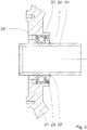
- Fig. 1 and 2 show a known from the prior art solution for integrating a pitch tube 101 in a transmission of a wind turbine.
- Fig. 1 represents a rotor-side attachment of the pitch tube 101.
- the pitch tube 101 is passed through an opening in a planetary carrier 103 driven by the rotor.
- a connection piece 105 is provided for coupling the pitch tube 101 with the planet carrier 103.
- This has a flange 107 which is screwed to the planet carrier 103.
- the pitch tube 101 is provided with two circumferential grooves 109 into each of which an O-ring 111 is inserted.
- the O-rings 111 seal the pitch tube 101 from the fitting 105.
- the pitch tube 101 is provided with a slot-shaped recess 113. In this engages a securing tab 115 that is attached to the connector 105.
- a rotationally fixed connection between the pitch tube 101 and the connecting piece 105 comes about.
- the pitch tube 101 and the planet carrier 103 are rotatably connected. The pitch tube 101 thus rotates with the rotor.
- Fig. 2 shows that in the Fig. 1 illustrated rotor-side end of the pitch tube 101 opposite generator-side end of the pitch tube 101.
- the pitch tube 101 passes through a housing 201 of the transmission through. Since the pitch tube 101 rotates with the planet carrier 103, but the housing 201 is fixed, the pitch tube 101 is rotatably mounted in the housing 201 by means of a bearing 203.
- a snap ring 205 which is mounted in the housing 201, and a snap ring 207, which is mounted on the pitch tube 101, fix the bearing 203 in the axial direction.
- a seal 209 prevents oil from the transmission between the housing 201 and the pitch tube 101 can pass.
- the pitch tube 101 serves as a bearing seat at its generator end. Therefore, the outer diameter of the pitch tube at this point as accurately as possible required for the bearing seat excess must comply with the diameter of the inner bearing ring.
- the publication DE 10 2010 060 147 A1 discloses a planetary gear for a wind turbine.
- the planetary gear has a central distributor for the delivery of lubricant, which extends within the gear housing and is designed as a double-walled annular channel. Through the interior of the ring channel cables can be passed.
- the object of the invention is to integrate a pitch tube in a gearbox of a wind turbine while avoiding the inherent disadvantages of the prior art solutions.
- the costs of the pitch tube and the effort required to produce the pitch tube should be reduced.
- connection piece for a pitch tube of a wind turbine with the features of claim 1.
- the connector according to the invention has a receptacle into which the pitch tube can be at least partially inserted. This does not exclude that the pitch tube can be passed through the receptacle.
- the receptacle is designed such that an opening of the pitch tube is located inside the connection piece when the pitch tube has been inserted into the receptacle. Since the pitch tube usually has the shape of a straight circular hollow cylinder, preferably also the receptacle is cylindrical, that encloses a straight circular cylinder.
- the connecting piece is designed at least in two pieces.
- a first part of the connecting piece forms a first of the at least two pieces
- a second part of the connecting piece forms a second of the at least two pieces.
- the first part and the second part form separate pieces of the connection piece.
- the first part has a first, at least partially annular sealing surface.
- the second part has a second, at least partially annular sealing surface.
- the first sealing surface and the second sealing surface thus each have at least one partial surface, which extends in a circular ring.
- the two partial surfaces are provided as contact surfaces for a seal.
- the two partial surfaces are radially aligned, that is, each extending in a radial, that is orthogonal to a rotational axis, aligned plane. Furthermore, an arrangement of the two partial surfaces coaxial with the axis of rotation is preferred. The two partial surfaces are thus rotationally symmetrical about an axis of symmetry which runs along the axis of rotation, that is, which is identical to the axis of rotation.
- the axis of rotation is preferably the axis of rotation of the pitch tube. This is preferably identical to the axis of rotation of a planet carrier and / or the axis of rotation of a rotor of the wind turbine, which may be connected in particular rotationally fixed to the planet carrier.
- the first sealing surface and the second sealing surface are arranged so that they form with a part of the surface, in particular the lateral surface, of the pitch tube at least part of a boundary surface of a cavity when the pitch tube has been inserted into the receptacle and is in the receptacle.
- the cavity is intended to receive the seal.
- the cavity is limited at least by the first sealing surface, the second sealing surface and the abovementioned part of the surface of the pitch tube.
- the first sealing surface and the second sealing surface are part of a coaxial with the axis of rotation within the receptacle extending recess or groove or groove or groove. In this recess, the seal can be introduced. If the pitch tube is inserted into the receptacle, the part of the surface of the pitch tube runs along the mouth of the depression and thus closes off the depression, so that the cavity is formed.
- the connecting piece comprises at least one means for clamping the first sealing surface and the second sealing surface against each other or against the seal.
- the means is used to move the first sealing surface and the second sealing surface in the axial direction, that is, in the direction of the axis of rotation, against each other.
- the connection piece For mounting the connection piece on the pitch tube, first the seal between the first sealing surface and the second sealing surface, that is introduced into the recess. Subsequently, the connector is inserted into the receptacle. By means of the first sealing surface and the second sealing surface can now be shifted towards each other so that the distance between the first sealing surface and the second sealing surface is reduced. This causes the first sealing surface and the second sealing surface to brace against the seal. This in turn leads to a deformation of the seal in the radial direction, in particular towards the inside. The seal is thus pressed against the pitch tube. In this case, the seal comes into contact with the pitch tube along a surface extending coaxially to the axis of rotation.
- connection piece is sealed off from the pitch tube, so that no oil can pass between the connection piece and the pitch tube.
- pitch tube is fixed in the connecting piece with respect to a displacement in the axial direction, that is to say in the direction of the axis of rotation.
- the connector according to the invention allows the use of almost any pitch tube, since comparatively large dimensional tolerances of the pitch tube can be compensated by the described deformation of the seal.
- a plastic pitch tube such as PVC-C or a glass fiber reinforced epoxy resin may be used.
- the pitch tube may be made of coated metal.
- the rotor and / or the rotor shaft and / or the planet carrier form the first part of the connection piece.
- the rotor and / or the rotor shaft and / or the planet carrier comprise the first part of the connection piece.
- the first part of the connecting piece is thus part of the rotor and / or the rotor shaft and / or the planet carrier.
- the rotor and / or the rotor shaft and / or the planet carrier can be made in one piece in one piece.
- the second part of the connection piece has a flange. With this, the second part can be screwed onto the first part. This reduces the distance between the first sealing surface and the second sealing surface, so that the first sealing surface and the second sealing surface are displaced towards each other and clamp against the seal.
- the flange is provided with holes through which screws can be passed. Accordingly, the second part threaded holes for receiving the screws.
- a second, provided with a flange portion of the connector is particularly suitable for the rotor-side recording of the pitch tube.
- the flange is preferably screwed to the rotor, the rotor shaft or the planet carrier, wherein the rotor and / or the rotor shaft and / or the planet carrier form the first part of the connection piece.
- a thread pairing serves to change the distance between the first sealing surface and the second sealing surface.
- the first part of the connector has a first thread of the thread pairing.
- the second part of the connecting piece accordingly has a second thread of the thread pairing.
- the connecting piece may have at least one groove into which a locking ring is introduced.
- the inner ring of the bearing and the first part of the connector can be made in one piece. This means that the first part of the fitting forms the bearing surface.
- the bearing is preferably a plain bearing. But also a one-piece design of the first part of the connector with the inner ring of a rolling bearing is possible.
- the bearing serves to support the pitch tube with respect to a fixed gear part.
- the outer ring of the bearing is mounted in the transmission part.
- the stationary transmission part may be a housing of the transmission.
- the pitch tube has the bearing seat. In this area, however, special requirements are placed on both the dimensional stability, as well as the load capacity. As a result of the displacement of the bearing seat or the bearing surface in the first part of the connection piece, the pitch tube no longer has to meet these requirements and can thus be tolerated more generously.
- a connecting piece with a first and / or a second part, which have a coupling for connecting at least one electrical line and / or at least one lubricant line.
- the coupling is thus part of the first part and / or the second part of the connection piece.
- the first part and / or the second part may be integrally connected to the coupling. This eliminates the need to provide a separate coupling and to attach this consuming the pitch tube.
- the connector 105 is made in two parts.
- the planet carrier 103 forms a first part of the connecting piece 105.
- the flange 107 forms a second part of the connecting piece 105.
- the connector 105 has no groove 109 for receiving a sealing element.
- the planet carrier 103 and the flange 107 each form an annular, radially aligned sealing surface 301, 303.
- the sealing surfaces 301, 303 are facing each other and form a rotationally symmetrical about a rotation axis 305 extending gap. In this gap is an O-ring 307.
- the pitch tube 101 may be inserted into a portion of the fitting 105 formed as a receptacle 309.
- the sealing surfaces 301, 303 are arranged so that the O-ring 307 is in contact with the sealing surfaces 301, 303 and the pitch tube 101 introduced into the receptacle 309.
- the O-ring 307 thus seals the sealing surfaces 301, 303 and thus the planet carrier 103 or the connecting piece 105 with respect to the pitch tube 101.
- the O-ring 307 prevents the oil from passing between the pitch pipe 101 and the planet carrier 103 and the fitting 105, respectively.
- the O-ring 307 prevents oil from getting inside the pitch tube 101.
- the flange 107 has through holes. Corresponding threaded holes are located in the planet carrier 103, so that the flange 107 on the planet carrier 103 can be screwed. This reduces the distance between the sealing surfaces 301, 303. This in turn has the consequence that the O-ring 307 deforms. The O-ring 307 is compressed by the sealing surfaces 301, 303.
- the O-ring 307 exerts a pressure on the pitch tube 101 along an area extending in the circumferential direction of the pitch tube 101.
- the pitch tube 101 is fixed in the connection piece 105.
- the deformation of the O-ring 307 equals dimensional deviations of the pitch tube 101.
- a coupling 311 serves to connect electrical leads passing through the pitch tube 101 to electrical leads routed within the rotor.
- the clutch 301 is integrally connected to the flange 107.
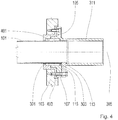
- Fig. 4 shows a variant of the embodiment Fig. 3 in which a sealing tube 401 is used instead of the O-ring 307.
- the sealing tube 401 has the shape of a hollow cylinder.
- the hollow space between the sealing surfaces 301, 303 is likewise correspondingly hollow-cylindrical.
- the sealing tube 401 and the gap have the shape of a rectangle.
- an intermediate piece 403 forms the first part of the connecting piece 105. Together with the flange 107 and the coupling 311, which form the second part of the connecting piece 105, the intermediate piece 403 screwed onto the planet carrier 103. This makes it possible, analogous to that in Fig. 3 illustrated variant, to reduce the distance between the sealing surfaces 301, 303 and so deform the sealing tube 401.
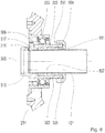
- a connector 501 as a generator-side counterpart to the connector 105 from Fig. 3 provides Fig. 5
- the fitting 501 comprises a sleeve 503 and a union nut 505.
- the sleeve 503 is provided with a receptacle 507 into which the pitch tube 101 can be inserted.
- the sleeve 503 and the union nut 505 each have a radially aligned annular sealing surface 509, 511 on.
- This gap serves to receive an O-ring 513.
- the sleeve 503 is integrally connected to a generator-side coupling 515.
- the coupling 515 serves to connect electrical lines arranged on the generator side to the electrical lines leading through the pitch tube 101.
- a securing tab 517 is arranged on the generator side. This is fixed in the sleeve 503 and engages in a generator-side groove 519 of the pitch tube 101. In this way, the generator-side connector 501 is rotatably coupled to the pitch tube 101.
- a variant of the fitting 501 provides Fig. 6 dar.
- the fitting 501 off Fig. 5 which has an O-ring 513 as a seal, comprises the fitting 501 according to FIG Fig. 6 a sealing tube 601. This is introduced instead of the O-ring 513 in the gap formed by the sealing surfaces 509, 511.
- the gap is designed correspondingly hollow cylindrical or rotationally symmetrical about the axis of rotation 305 with a rectangular cross-section.
- the pitch tube 101 with the rotor-side groove 113 and the generator-side groove 519 Fig. 7 represents.
Landscapes
- Engineering & Computer Science (AREA)
- Mechanical Engineering (AREA)
- Sustainable Development (AREA)
- Sustainable Energy (AREA)
- Chemical & Material Sciences (AREA)
- Combustion & Propulsion (AREA)
- Life Sciences & Earth Sciences (AREA)
- General Engineering & Computer Science (AREA)
- Physics & Mathematics (AREA)
- Fluid Mechanics (AREA)
- Wind Motors (AREA)
- Gasket Seals (AREA)
- Connection Of Motors, Electrical Generators, Mechanical Devices, And The Like (AREA)
Description
- Die Erfindung betrifft ein Anschlussstück für ein Pitchrohr einer Windkraftanlage nach dem Oberbegriff von Anspruch 1.
- Mit Pitchrohr wird in Fachkreisen ein Leitungsrohr in einer Windkraftanlage bezeichnet, wobei mindestens ein Teil des Leitungsrohrs mindestens teilweise durch eine Rotorwelle der Windkraftanlage verläuft. Die Rotorwelle verbindet einen Rotor, aufweisend eine Rotornabe und vom Wind angetriebene Rotorblätter, drehfest - mit einer Eingangswelle eines Getriebes. Das Pitchrohr verläuft koaxial zu der Drehachse der Rotorwelle beziehungsweise des Rotors, das heißt das Pitchrohr ist rotationssymmetrisch mit einer Rotationsachse, die entlang der Drehachse der Rotorwelle beziehungsweise des Rotors verläuft, also identisch mit der Drehachse der Rotorwelle beziehungsweise des Rotors ist.
- Um eine Blatteinstellwinkelregelung (Pitchregelung) vornehmen zu können, sind elektrische Leitungen erforderlich, die zwischen dem Rotor und einem generatorseitigen Anschluss verlaufen. Das Pitchrohr dient unter anderem dazu, diese Leitungen durch die Rotorwelle zu verlegen.
- Auch ist es möglich, das Pitchrohr zur Ölversorgung eines Getriebes der Windkraftanlage zu verwenden. So schlägt die Druckschrift
DE 10 2011 119 471 A1 ein doppelwandiges Pitchrohr mit einem äußeren und einem inneren Rohr vor. Der zwischen dem inneren und dem äußeren Rohr gebildete Hohlraum dient dabei der Zuführung von Schmierstoff zu dem Getriebe. Die elektrischen Leitungen verlaufen durch das innere Rohr. - Die
Fig. 1 und2 zeigen eine aus dem Stand der Technik bekannte Lösung zur Integration eines Pitchrohrs 101 in ein Getriebe einer Windkraftanlage.Fig. 1 stellt eine rotorseitige Befestigung des Pitchrohrs 101 dar. Das Pitchrohr 101 wird durch eine Öffnung in einem von dem Rotor angetriebenen Planetenträger 103 hindurchgeführt. - Zur Kopplung des Pitchrohrs 101 mit dem Planetenträger 103 ist ein Anschlussstück 105 vorgesehen. Dieses weist einen Flansch 107 auf, der mit dem Planetenträger 103 verschraubt ist. Um zu verhindern, dass zwischen dem Pitchrohr und dem Anschlussstück 105 Öl aus dem Getriebe austreten kann, ist das Pitchrohr 101 mit zwei umlaufenden Nuten 109 versehen, in die jeweils ein O-Ring 111 eingesetzt ist. Die O-Ringe 111 dichten das Pitchrohr 101 gegenüber dem Anschlussstück 105 ab. Weiterhin ist das Pitchrohr 101 mit einer schlitzförmigen Aussparung 113 versehen. In diese greift eine Sicherungslasche 115 ein, dass an dem Anschlussstück 105 angebracht ist. Dadurch kommt eine drehfeste Verbindung zwischen dem Pitchrohr 101 und dem Anschlussstück 105 zustande. Insbesondere sind auch das Pitchrohr 101 und der Planetenträger 103 drehfest verbunden. Das Pitchrohr 101 dreht sich also mit dem Rotor.
-
Fig. 2 zeigt das dem inFig. 1 dargestellten rotorseitigen Ende des Pitchrohrs 101 gegenüberliegende generatorseitige Ende des Pitchrohrs 101. Generatorseitig führt das Pitchrohr 101 durch ein Gehäuse 201 des Getriebes hindurch. Da sich das Pitchrohr 101 mit dem Planetenträger 103 dreht, das Gehäuse 201 aber feststeht, ist das Pitchrohr 101 in dem Gehäuse 201 mittels eines Lagers 203 drehbar gelagert. Ein Sicherungsring 205, der in dem Gehäuse 201 angebracht ist, und ein Sicherungsring 207, der auf dem Pitchrohr 101 angebracht ist, fixieren das Lager 203 in axialer Richtung. Eine Dichtung 209 verhindert, dass Öl aus dem Getriebe zwischen dem Gehäuse 201 und dem Pitchrohr 101 hindurchtreten kann. - Bei der beschriebenen Lösung werden an die Maßhaltigkeit des Pitchrohrs 101 hohe Anforderungen gestellt. Zum einen muss der zwischen dem Pitchrohr 101 und dem Anschlussstück 105 verlaufende Spalt sehr schmal sein. Andernfalls wäre die Dichtwirkung der O-Ringe 111 mangelhaft, so dass durch den Spalt Öl aus dem Getriebe austreten könnte. Andererseits dient das Pitchrohr 101 an seinem generatorseitigen Ende als Lagersitz. Daher muss der Außendurchmesser des Pitchrohrs an dieser Stelle möglichst genau ein für den Lagersitz erforderliches Übermaß zu dem Durchmesser des inneren Lagerrings einhalten.
- Mit dem Pitchrohr 101 rotieren auch die in dem Pitchrohr 101 verlegten elektrischen Leitungen. Daher ist eine Kupplung erforderlich, um generatorseitig drehfest verlegte Leitungen mit den rotierenden Leitungen in dem Pitchrohr 101 zu verbinden. Das Pitchrohr 101 muss daher generatorseitig so ausgebildet sein, dass es mit der Kupplung verbunden werden kann. Auch muss der generatorseitige Anschluss in der Regel Spezifikationen entsprechen, die der Anlagenhersteller vorgibt.
- Die Druckschrift
DE 10 2010 060 147 A1 offenbart ein Planetengetriebe für eine Windkraftanlage. Das Planetengetriebe weist einen Zentralverteiler zur Förderung von Schmierstoff auf, der sich innerhalb des Getriebegehäuses erstreckt und als doppelwandiger Ringkanal ausgeführt ist. Durch das Innere des Ringkanals können Kabel hindurchgeführt werden. - Aus der Druckschrift
CH 666 106 A5 - Aufgabe der Erfindung ist es, unter Vermeidung der den aus dem Stand der Technik bekannten Lösungen innewohnenden Nachteilen ein Pitchrohr in ein Getriebe einer Windkraftanlage zu integrieren. Insbesondere sollen die Kosten des Pitchrohrs und der zur Herstellung des Pitchrohrs erforderliche Aufwand reduziert werden.
- Diese Aufgabe wird durch ein Anschlussstück für ein Pitchrohr einer Windkraftanlage mit den Merkmalen von Anspruch 1 gelöst.
- Das erfindungsgemäße Anschlussstück weist eine Aufnahme auf, in die das Pitchrohr mindestens teilweise eingeführt werden kann. Dies schließt nicht aus, dass das Pitchrohr durch die Aufnahme hindurchgeführt werden kann. Vorzugsweise ist die Aufnahme aber so ausgebildet, dass sich eine Mündung des Pitchrohrs im Inneren des Anschlussstücks befindet, wenn das Pitchrohr in die Aufnahme eingeführt wurde. Da das Pitchrohr in der Regel die Form eines geraden kreisförmigen Hohlzylinders hat, ist vorzugsweise auch die Aufnahme zylinderförmig ausgeführt, d.h. umschließt einen geraden kreisförmigen Zylinder.
- Erfindungsgemäß ist das Anschlussstück mindestens zweistückig ausgeführt. Dabei bildet ein erster Teil des Anschlussstücks ein erstes der mindestens zwei Stücke, ein zweiter Teil des Anschlussstücks ein zweites der mindestens zwei Stücke. Der erste Teil und der zweite Teil bilden separate bzw. voneinander getrennte Stücke des Anschlussstücks.
- Der erste Teil weist eine erste, mindestens teilweise kreisringförmige Dichtfläche auf. Entsprechend weist der zweite Teil eine zweite, mindestens teilweise kreisringförmige Dichtfläche auf. Die erste Dichtfläche und die zweite Dichtfläche weisen also jeweils mindestens eine Teilfläche auf, die kreisringförmig verläuft. Die beiden Teilflächen sind als Kontaktflächen für eine Dichtung vorgesehen.
- Bevorzugt sind die beiden Teilflächen radial ausgerichtet, das heißt verlaufen jeweils in einer radial, das heißt orthogonal zu einer Drehachse, ausgerichteten Ebene. Weiterhin bevorzugt wird eine zu der Drehachse koaxialer Anordnung der beiden Teilflächen. Die beiden Teilflächen sind also rotationssymmetrisch um eine Symmetrieachse, die entlang der Drehachse verläuft, das heißt die identisch mit der Drehachse ist.
- Bei der Drehachse handelt es sich vorzugsweise um die Drehachse des Pitchrohrs. Diese ist vorzugsweise identisch mit der Drehachse eines Planetenträgers und/oder der Drehachse eines Rotors der Windkraftanlage, der insbesondere drehfest mit dem Planetenträger verbunden sein kann.
- Die erste Dichtfläche und die zweite Dichtfläche sind so angeordnet, dass sie mit einem Teil der Oberfläche, insbesondere der Mantelfläche, des Pitchrohrs mindestens einen Teil einer Begrenzungsfläche eines Hohlraums bilden, wenn das Pitchrohr in die Aufnahme eingeführt wurde und sich in der Aufnahme befindet. Der Hohlraum ist dazu vorgesehen, die Dichtung aufzunehmen. Begrenzt wird der Hohlraum mindestens von der ersten Dichtfläche, der zweiten Dichtfläche und dem obengenannten Teil der Oberfläche des Pitchrohrs. Die erste Dichtfläche und die zweite Dichtfläche sind Teil einer koaxial zu der Drehachse innerhalb der Aufnahme verlaufenden Vertiefung bzw. Aussparung bzw. Rinne bzw. Nut. In diese Vertiefung kann die Dichtung eingebracht werden. Wird das Pitchrohr in die Aufnahme eingeführt, verläuft der Teil der Oberfläche des Pitchrohrs entlang der Mündung der Vertiefung und schließt somit die Vertiefung ab, so dass der Hohlraum gebildet wird.
- Das Anschlussstück umfasst mindestens ein Mittel, um die erste Dichtfläche und die zweite Dichtfläche gegeneinander bzw. gegen die Dichtung zu verspannen. Insbesondere dient das Mittel dazu, die erste Dichtfläche und die zweite Dichtfläche in axialer Richtung, das heißt in Richtung der Drehachse, gegeneinander zu verschieben.
- Zur Montage des Anschlussstücks auf dem Pitchrohr wird zunächst die Dichtung zwischen die erste Dichtfläche und die zweite Dichtfläche, das heißt in die Vertiefung, eingebracht. Darauffolgend wird das Anschlussstück in die Aufnahme eingeführt. Durch das Mittel können nun die erste Dichtfläche und die zweite Dichtfläche so zueinander hin verschoben werden, dass sich der Abstand zwischen der ersten Dichtfläche und der zweiten Dichtfläche verringert. Dies führt dazu, dass die erste Dichtfläche und die zweite Dichtfläche sich gegen die Dichtung verspannen. Dies wiederum führt zu einer Verformung der Dichtung in radialer Richtung, insbesondere nach innen hin. Die Dichtung wird somit gegen das Pitchrohr gedrückt. Dabei tritt die Dichtung mit dem Pitchrohr entlang einer koaxial zu der Drehachse verlaufenden Fläche in Kontakt. Hierdurch erfolgt eine Abdichtung des Anschlussstücks gegenüber dem Pitchrohr, so dass kein Öl zwischen dem Anschlussstück und dem Pitchrohr hindurchtreten kann. Zudem wird das Pitchrohr in dem Anschlussstück gegenüber einer Verschiebung in axialer Richtung, das heißt in Richtung der Drehachse, fixiert.
- Das erfindungsgemäße Anschlussstück ermöglicht die Verwendung eines nahezu beliebigen Pitchrohrs, da durch die beschriebene Verformung der Dichtung vergleichsweise große Maßtoleranzen des Pitchrohrs ausgeglichen werden können. Insbesondere kann ein Pitchrohr aus Kunststoff wie etwa PVC-C oder einem glasfaserverstärkten Epoxidharz verwendet werden. Auch kann das Pitchrohr aus beschichtetem Metall bestehen.
- In einer bevorzugten Weiterbildung der Erfindung bilden der Rotor und/oder die Rotorwelle und/oder der Planetenträger den ersten Teil des Anschlussstücks. Dies bedeutet, dass der Rotor und/oder die Rotorwelle und/oder der Planetenträger den ersten Teil des Anschlussstücks umfassen. Der erste Teil des Anschlussstücks ist also Teil des Rotors und/oder der Rotorwelle und/oder des Planetenträgers. Insbesondere können dabei der Rotor und/oder die Rotorwelle und/oder der Planetenträgers einstückig einstückig ausgeführt sein. Durch diese Integration des ersten Teils in den Rotor und/oder die Rotorwelle und/oder den Planetenträger verringern sich die Anzahl der Teile des Getriebes und damit dessen Herstellungskosten.
- In einer darüber hinaus bevorzugten Weiterbildung weist der zweite Teil des Anschlussstücks einen Flansch auf. Mit diesem kann der zweite Teil auf den ersten Teil aufgeschraubt werden. Hierdurch reduziert sich der Abstand zwischen der ersten Dichtfläche und der zweiten Dichtfläche, so dass die erste Dichtfläche und die zweite Dichtfläche zueinander hin verschoben werden und sich gegen die Dichtung verspannen.
- Insbesondere ist der Flansch mit Bohrungen versehen, durch die Schrauben geführt werden können. Entsprechend weist der zweite Teil Gewindebohrungen zur Aufnahme der Schrauben auf. Ein zweiter, mit einem Flansch versehener Teil des Anschlussstücks ist insbesondere für die rotorseitige Aufnahme des Pitchrohrs geeignet. Dabei wird der Flansch bevorzugt mit dem Rotor, der Rotorwelle oder dem Planetenträger verschraubt, wobei der Rotor und/oder die Rotorwelle und/oder der Planetenträger den ersten Teil des Anschlussstücks bilden.
- Anstelle des Flansches dient in einer weiterhin bevorzugten Weiterbildung eine Gewindepaarung dazu, den Abstand zwischen der ersten Dichtfläche und der zweiten Dichtfläche zu verändern. Der erste Teil des Anschlussstücks weist dabei ein erstes Gewinde der Gewindepaarung auf. Der zweite Teil des Anschlussstücks weist entsprechend ein zweites Gewinde der Gewindepaarung auf. Durch Verdrehen des ersten Gewindes gegenüber dem zweiten Gewinde verändert sich der Abstand zwischen der ersten Dichtfläche und der zweiten Dichtfläche. Wird das erste Gewinde in das zweite Gewinde beziehungsweise das zweite Gewinde in das erste Gewinde eingeschraubt, werden somit die erste Dichtfläche und die zweite Dichtfläche gegen die Dichtung verspannt.
- Besonders bevorzugt, insbesondere für die generatorseitige Aufnahme des Pitchrohrs, wird eine Weiterbildung mit einem ersten Teil des Anschlussstücks, der einen Lagersitz oder eine Lagerlauffläche bildet. Der Lagersitz dient der Aufnahme eines Lagers, insbesondere eines Innenrings des Lagers. Das Lager kann also mit seinem Innenring auf den Lagersitz aufgeschoben werden. Dabei dient der Lagersitz dazu, das Lager in radialer Richtung zu fixieren. Zur Fixierung des Lagers beziehungsweise seines Innenrings in axialer Richtung kann das Anschlussstück mindestens eine Nut aufweisen, in die ein Sicherungsring eingebracht wird.
- Der Innenring des Lagers und der erste Teil des Anschlussstücks können einstückig ausgeführt sein. Das bedeutet, dass der erste Teil des Anschlussstücks die Lagerlauffläche bildet. In diesem Fall handelt es sich bei dem Lager bevorzugt um ein Gleitlager. Aber auch eine einstückige Ausführung des ersten Teils des Anschlussstücks mit dem Innenring eines Wälzlagers ist möglich.
- Das Lager dient dazu, das Pitchrohr gegenüber einem feststehenden Getriebeteil abzustützen. Der Außenring des Lagers wird dabei in dem Getriebeteil angebracht. Insbesondere kann es sich bei dem feststehenden Getriebeteil um ein Gehäuse des Getriebes handeln.
- Bei den aus dem Stand der Technik bekannten Lösungen weist das Pitchrohr den Lagersitz auf. In diesem Bereich werden aber besondere Anforderungen sowohl an die Maßhaltigkeit, als auch an die Belastbarkeit gestellt. Infolge der Verlagerung des Lagersitzes beziehungsweise der Lagerlauffläche in den ersten Teil des Anschlussstücks muss das Pitchrohr diese Anforderungen nicht mehr erfüllen und kann somit großzügiger toleriert werden.
- Weiterhin bevorzugt wird ein Anschlussstück mit einem ersten und/oder einem zweiten Teil, die eine Kupplung zum Anschluss mindestens einer elektrischen Leitung und/oder mindestens einer Schmierstoffleitung aufweisen. Die Kupplung ist also Teil des ersten Teils und/oder des zweiten Teils des Anschlussstücks. Insbesondere können der erste Teil und/oder der zweite Teil einstückig mit der Kupplung verbunden sein. Hierdurch entfällt die Notwendigkeit, eine separate Kupplung vorzusehen und diese aufwändig an dem Pitchrohr befestigen zu müssen.
- Die
Fig. 1 und2 geben aus dem Stand der Technik bekannte Lösungen wieder. Ausführungsbeispiele der Erfindung, die im Folgenden näher erläutert werden, sind in denFig. 3 bis 7 dargestellt. Dabei kennzeichnen übereinstimmende Bezugszeichen gleiche oder funktionsgleiche Merkmale. Im Einzelnen zeigt - Fig. 1
- ein aus dem Stand der Technik bekanntes rotorseitiges Anschlussstück;
- Fig. 2
- ein aus dem Stand der Technik bekanntes generatorseitiges Anschlussstück;
- Fig. 3
- ein rotorseitiges Anschlussstück mit verspannbarem O-Ring;
- Fig. 4
- ein rotorseitiges Anschlussstück mit verspannbarem Dichtungsschlauch;
- Fig. 5
- ein generatorseitiges Anschlussstück mit verspannbarem O-Ring;
- Fig. 6
- ein generatorseitiges Anschlussstück mit verspannbarem Dichtungsschlauch; und
- Fig. 7
- ein Pitchrohr.
- Gemäß
Fig. 3 ist das Anschlussstück 105 zweiteilig ausgeführt. Einen ersten Teil des Anschlussstücks 105 bildet der Planetenträger 103. Der Flansch 107 bildet einen zweiten Teil des Anschlussstücks 105. Im Unterschied zu der inFig. 1 dargestellten Lösung weist das Anschlussstück 105 keine Nut 109 zur Aufnahme eines Dichtungselements auf. Stattdessen bilden der Planetenträger 103 und der Flansch 107 jeweils eine kreisringförmige radial ausgerichtete Dichtfläche 301, 303 aus. Die Dichtflächen 301, 303 sind einander zugewandt und bilden einen rotationssymmetrisch um eine Drehachse 305 verlaufenden Spalt. In diesem Spalt befindet sich ein O-Ring 307. - Das Pitchrohr 101 kann in einen als Aufnahme 309 ausgebildeten Bereich des Anschlussstücks 105 eingeführt werden. Die Dichtflächen 301, 303 sind so angeordnet, dass der O-Ring 307 mit den Dichtflächen 301, 303 und dem in die Aufnahme 309 eingeführten Pitchrohr 101 in Kontakt steht. Der O-Ring 307 dichtet also die Dichtflächen 301, 303 und damit den Planetenträger 103 beziehungsweise das Anschlussstück 105 gegenüber dem Pitchrohr 101 ab. Somit verhindert der O-Ring 307, das Öl zwischen dem Pitchrohr 101 und dem Planetenträger 103 beziehungsweise dem Anschlussstück 105 hindurchtreten kann. Insbesondere verhindert der O-Ring 307, dass Öl ins Innere des Pitchrohrs 101 gelangt.
- Der Flansch 107 weist Durchgangsbohrungen auf. Entsprechende Gewindebohrungen befinden sich in dem Planetenträger 103, so dass der Flansch 107 auf den Planetenträger 103 aufgeschraubt werden kann. Dabei verringert sich der Abstand zwischen den Dichtflächen 301, 303. Dies wiederum hat zur Folge, dass sich der O-Ring 307 verformt. Der O-Ring 307 wird von den Dichtflächen 301, 303 zusammengedrückt.
- Infolge der Verformung übt der O-Ring 307 entlang einer in Umfangsrichtung des Pitchrohrs 101 verlaufenden Fläche einen Druck auf das Pitchrohr 101 auf. Hierdurch wird das Pitchrohr 101 in dem Anschlussstück 105 fixiert. Weiterhin gleicht die Verformung des O-Rings 307 Maßabweichungen des Pitchrohrs 101.
- Eine Kupplung 311 dient dazu, elektrische Leitungen, die durch das Pitchrohr 101 verlaufen, mit elektrischen Leitungen zu verbinden, die innerhalb des Rotors verlegt sind. Die Kupplung 301 ist einstückig mit dem Flansch 107 verbunden.
-
Fig. 4 zeigt eine Variante des Ausführungsbeispiels ausFig. 3 , bei der statt des O-Rings 307 ein Dichtungsschlauch 401 verwendet wird. Der Dichtungsschlauch 401 hat die Form eines Hohlzylinders. Ebenfalls hohlzylinderförmig ausgebildet ist entsprechend der Spalt zwischen den Dichtungsflächen 301, 303. Im Querschnitt haben Dichtungsschlauch 401 und der Spalt die Form eines Rechtecks. - Der Dichtungsschlauch 401 überragt in axialer Richtung den Planetenträger 103. Statt des Planetenträgers 103 bildet deshalb ein Zwischenstück 403 den ersten Teil des Anschlussstücks 105. Zusammen mit dem Flansch 107 und der Kupplung 311, die den zweiten Teil des Anschlussstücks 105 bilden, ist das Zwischenstück 403 auf den Planetenträger 103 aufgeschraubt. Dies ermöglicht es, analog zu der in
Fig. 3 dargestellten Variante, den Abstand zwischen den Dichtflächen 301, 303 zu verringern und so den Dichtungsschlauch 401 zu verformen. - Ein Anschlussstück 501 als generatorseitiges Pendant zu dem Anschlussstück 105 aus
Fig. 3 stelltFig. 5 dar. Das Anschlussstück 501 umfasst eine Hülse 503 und eine Überwurfmutter 505. Die Hülse 503 ist mit einer Aufnahme 507 versehen, in die das Pitchrohr 101 eingeführt werden kann. Die Hülse 503 und die Überwurfmutter 505 weisen jeweils eine radial ausgerichtete kreisringförmige Dichtfläche 509, 511 auf. - Zwischen den Dichtflächen 509, 511 verläuft ein Spalt, der zu der Drehachse 305 rotationssymmetrisch ist. Dieser Spalt dient der Aufnahme eines O-Rings 513.
- Wenn die Überwurfmutter 505 auf die Hülse 503 aufgeschraubt wird, verringert sich der Abstand der beiden Dichtflächen 509, 511 zueinander. Infolgedessen verkleinert sich der Spalt, so dass der O-Ring 513 verformt und gegen das Pitchrohr 101 gedrückt wird.
- Die Hülse 503 ist einstückig mit einer generatorseitigen Kupplung 515 verbunden. Die Kupplung 515 dient dazu, generatorseitig angeordnete elektrische Leitungen mit den durch das Pitchrohr 101 hindurchführenden elektrischen Leitungen zu verbinden.
- Auch generatorseitig ist eine Sicherungslasche 517 angeordnet. Diese ist in der Hülse 503 fixiert und greift in eine generatorseitige Nut 519 des Pitchrohrs 101 ein. Auf diese Weise wird das generatorseitige Anschlussstück 501 drehfest mit dem Pitchrohr 101 gekoppelt.
- Um das Pitchrohr 101 mit dem generatorseitigen Anschlussstück 501 drehbar in dem Getriebegehäuse 201 zu lagern, eignen sich aus dem Stand der Technik bekannte Lagerungskonzepte, etwa das in
Fig. 2 dargestellte Lagerungskonzept. Allerdings ist gemäßFig. 5 die Lagerung, insbesondere das Lager 203, mit dem zugehörigen Sicherungsring 205 nicht direkt auf dem Pitchrohr 101 angebracht, sondern auf der Hülse 503. Der Außendurchmesser des Pitchrohrs 101 muss also nicht dem Innendurchmesser des Lagers 203 entsprechen. Die durch die Lagerung gestellten Anforderungen an die Fertigungsgüte, insbesondere an die Fertigungstoleranzen, müssen hier also nicht von dem Pitchrohr 101 erfüllt werden, sondern lediglich von der Hülse 503. - Eine Variante des Anschlussstücks 501 stellt
Fig. 6 dar. Im Gegensatz zu dem Anschlussstück 501 ausFig. 5 , das als Dichtung einen O-Ring 513 aufweist, umfasst das Anschlussstück 501 gemäßFig. 6 einen Dichtungsschlauch 601. Dieser wird anstelle des O-Rings 513 in den von den Dichtflächen 509, 511 gebildeten Spalt eingebracht. Der Spalt ist entsprechend hohlzylinderförmig ausgeführt beziehungsweise rotationssymmetrisch um die Drehachse 305 mit einem rechteckigen Querschnitt. - Das Pitchrohr 101 mit der rotorseitigen Nut 113 und der generatorseitigen Nut 519 stellt
Fig. 7 dar. -
- 101
- Pitchrohr
- 103
- Planetenträger
- 105
- Anschlussstück
- 107
- Flansch
- 109
- Nut
- 111
- O-Ring
- 113
- Aussparung
- 115
- Sicherungslasche
- 201
- Gehäuse
- 203
- Lager
- 205
- Sicherungsring
- 207
- Sicherungsring
- 209
- Dichtung
- 301
- Dichtfläche
- 303
- Dichtfläche
- 305
- Drehachse
- 309
- Aufnahme
- 307
- O-Ring
- 311
- Kupplung
- 401
- Dichtungsschlauch
- 403
- Zwischenstück
- 501
- Anschlussstück
- 503
- Hülse
- 505
- Überwurfmutter
- 507
- Aufnahme
- 509
- Dichtfläche
- 511
- Dichtfläche
- 513
- O-Ring
- 515
- Kupplung
- 517
- Sicherungslasch
- 601
- Dichtungsschlauch
Claims (5)
- Anschlussstück (105, 501) für ein Pitchrohr (101) einer Windkraftanlage, wobei
das Anschlussstück (105, 501) eine Aufnahme (309, 507) aufweist, in die das Pitchrohr (101) mindestens teilweise eingeführt werden kann; wobei
das Anschlussstück (105, 501) mindestens zweistückig, mit einem ersten Teil (103, 503) und einem zweiten Teil (107, 311, 505), ausgeführt ist; wobei der erste Teil (103, 503) eine erste, mindestens teilweise kreisringförmige Dichtfläche (301, 509) aufweist; wobei
der zweite Teil (107, 311, 505) eine zweite, mindestens teilweise kreisringförmige Dichtfläche (303, 511) aufweist; und wobei
die erste Dichtfläche (301, 509) und die zweite Dichtfläche (303, 511) mit einem Teil der Oberfläche des Pitchrohrs (101) mindestens einen Teil einer Begrenzungsfläche eines Hohlraums zur Aufnahme einer Dichtung (307, 401, 513, 601) bilden, wenn das Pitchrohr (101) in die Aufnahme (309, 507) eingeführt wurde; gekennzeichnet durch
mindestens eine Mittel zum Verändern des Abstands zwischen der ersten Dichtfläche (301, 509) und der zweite Dichtfläche (303, 511); wobei
ein Rotor und/oder eine Rotorwelle und/oder ein Planetenträger (103) der Windkraftanlage den ersten Teil des Anschlussstücks (105) bildet. - Anschlussstück (105) nach Anspruch 1, dadurch gekennzeichnet, dass
der zweite Teil (107, 311) des Anschlussstücks (105) einen Flansch (107) aufweist, mit dem der zweite Teil (107, 311) auf den ersten Teil (103) aufgeschraubt werden kann, sodass die erste Dichtfläche (301, 509) und die zweite Dichtfläche (303, 511) gegen die Dichtung (307, 401) verspannt werden können. - Anschlussstück (501) nach Anspruch 1, dadurch gekennzeichnet, dass
der erste Teil (503) des Anschlussstücks (501) ein erstes Gewinde und der zweite Teil (505) des Anschlussstücks (501) ein zweites Gewinde aufweist, wobei der Abstand zwischen der ersten Dichtfläche (509) und der zweite Dichtfläche (511) verändert werden kann, indem das erste Gewinde und das zweite Gewinde miteinander verschraubt werden. - Anschlussstück (501) nach einem der vorhergehenden Ansprüche, dadurch gekennzeichnet, dass
der erste Teil (503) des Anschlussstücks (501) einen Lagersitz oder eine Lagerlauffläche bildet. - Anschlussstück (105, 501) nach einem der vorhergehenden Ansprüche, dadurch gekennzeichnet, dass
der erste Teil (103, 503) und/oder der zweite Teil (107, 311, 505) des Anschlussstücks eine Kupplung (311, 515) zum Anschluss mindestens einer elektrischen Leitung und/oder mindestens einer Schmierstoffleitung aufweist.
Applications Claiming Priority (2)
| Application Number | Priority Date | Filing Date | Title |
|---|---|---|---|
| DE102014200674.0A DE102014200674A1 (de) | 2014-01-16 | 2014-01-16 | Anschlussstück für ein Pitchrohr |
| PCT/EP2014/077702 WO2015106898A1 (de) | 2014-01-16 | 2014-12-15 | Anschlussstück für ein pitchrohr |
Publications (2)
| Publication Number | Publication Date |
|---|---|
| EP3094861A1 EP3094861A1 (de) | 2016-11-23 |
| EP3094861B1 true EP3094861B1 (de) | 2019-11-27 |
Family
ID=52232161
Family Applications (1)
| Application Number | Title | Priority Date | Filing Date |
|---|---|---|---|
| EP14820810.1A Active EP3094861B1 (de) | 2014-01-16 | 2014-12-15 | Anschlussstück für ein pitchrohr |
Country Status (5)
| Country | Link |
|---|---|
| US (1) | US10359029B2 (de) |
| EP (1) | EP3094861B1 (de) |
| DE (1) | DE102014200674A1 (de) |
| ES (1) | ES2762546T3 (de) |
| WO (1) | WO2015106898A1 (de) |
Cited By (1)
| Publication number | Priority date | Publication date | Assignee | Title |
|---|---|---|---|---|
| EP4345300A1 (de) * | 2022-09-28 | 2024-04-03 | Flender GmbH | Betriebssicheres pitchrohr für eine blatteinstellwinkelregelung einer windkraftanlage |
Families Citing this family (11)
| Publication number | Priority date | Publication date | Assignee | Title |
|---|---|---|---|---|
| DE102015223669B4 (de) | 2015-11-30 | 2023-09-21 | Zf Friedrichshafen Ag | Planetengetriebe für eine Windkraftanlage und Verfahren zur Montage des Planetengetriebes |
| DE102016202735A1 (de) | 2016-02-23 | 2017-08-24 | Zf Friedrichshafen Ag | Teilbares Pitchrohr |
| CN107387743B (zh) * | 2017-08-24 | 2023-02-17 | 重庆望江工业有限公司 | 一种大型风电齿轮箱行星架轴承布置结构 |
| DE102017221362A1 (de) | 2017-11-29 | 2019-05-29 | Zf Friedrichshafen Ag | Fixierung eines Pitchrohrs |
| JP6841806B2 (ja) * | 2018-10-05 | 2021-03-10 | ファナック株式会社 | 回転力伝達部品 |
| EP3795862B2 (de) * | 2019-09-20 | 2024-12-18 | ZF Friedrichshafen AG | Elektrisch isoliertes durchführungsrohr |
| FI3795825T4 (fi) | 2019-09-20 | 2024-10-30 | Zahnradfabrik Friedrichshafen | Sähköisesti eristetty läpivientiputki |
| EP3798470B1 (de) * | 2019-09-27 | 2023-03-08 | Flender GmbH | Planetengetriebe mit verbesserter schmierstoffversorgung, antriebsstrang und windkraftanlage |
| EP4051899B1 (de) * | 2019-10-31 | 2024-12-04 | Vestas Wind Systems A/S | Vorrichtung zum abdichten von drehbaren bauteilen eines windturbinenantriebsstrangs |
| EP3954925A1 (de) * | 2020-08-11 | 2022-02-16 | Flender GmbH | Getriebe mit ölversorgung für kerbverzahnung sowie windkrfatanlage mit einem solchen getriebe sowie computerimplemnetiertes verfahren zur simulation eines solchen getriebes |
| DE102023207306A1 (de) * | 2023-07-31 | 2025-02-06 | Zf Wind Power Antwerpen N.V. | Anordnung zum Abdichten eines Pitchrohrs |
Family Cites Families (11)
| Publication number | Priority date | Publication date | Assignee | Title |
|---|---|---|---|---|
| SE8204648D0 (sv) * | 1982-08-11 | 1982-08-11 | Andrzej Tomasz Iwanicki | Rorkoppling |
| CH666106A5 (en) * | 1984-11-07 | 1988-06-30 | Fischer Ag Georg | Pipe joint with integral lip and sealing ring - is formed of elastomer, exerting radial grip on pipe while axial bracing is limited by metallic end washer |
| EP0192015A1 (de) * | 1985-02-12 | 1986-08-27 | Valter Söderberg | Dichtvorrichtung |
| DK1995454T3 (en) * | 2007-05-25 | 2016-06-13 | Siemens Ag | Device for regulating the inclination angle of a rotor blade of a wind turbine |
| US8365866B2 (en) * | 2008-07-10 | 2013-02-05 | General Electric Company | Internal lubrication for a gearbox, a power-generating wind turbine system, and a power-generating system |
| US8075442B2 (en) * | 2008-09-05 | 2011-12-13 | General Electric Company | System and assembly for power transmission and generation in a wind turbine |
| US7815536B2 (en) * | 2009-01-16 | 2010-10-19 | General Electric Company | Compact geared drive train |
| US8376708B2 (en) * | 2009-06-30 | 2013-02-19 | General Electric Company | Drivetrain system for a wind turbine generator and method of assembling the same |
| DE102010060147B4 (de) | 2010-10-25 | 2017-03-09 | Eickhoff Antriebstechnik Gmbh | Planetengetriebe mit einem Zentralverteiler |
| DE102011081861A1 (de) * | 2011-05-17 | 2012-11-22 | Winergy Ag | Antriebssystem für eine Windkraftanlage |
| DE102011119471A1 (de) | 2011-11-25 | 2013-05-29 | Robert Bosch Gmbh | Vorrichtung zur Übertragung von Versorgungsmitteln durch einen Antriebsstrang einer Windkraftanlage |
-
2014
- 2014-01-16 DE DE102014200674.0A patent/DE102014200674A1/de not_active Withdrawn
- 2014-12-15 US US15/110,786 patent/US10359029B2/en active Active
- 2014-12-15 EP EP14820810.1A patent/EP3094861B1/de active Active
- 2014-12-15 ES ES14820810T patent/ES2762546T3/es active Active
- 2014-12-15 WO PCT/EP2014/077702 patent/WO2015106898A1/de not_active Ceased
Non-Patent Citations (1)
| Title |
|---|
| None * |
Cited By (4)
| Publication number | Priority date | Publication date | Assignee | Title |
|---|---|---|---|---|
| EP4345300A1 (de) * | 2022-09-28 | 2024-04-03 | Flender GmbH | Betriebssicheres pitchrohr für eine blatteinstellwinkelregelung einer windkraftanlage |
| WO2024068191A1 (de) * | 2022-09-28 | 2024-04-04 | Flender Gmbh | Betriebssicheres pitchrohr für eine blatteinstellwinkelregelung einer windkraftanlage |
| CN119998545A (zh) * | 2022-09-28 | 2025-05-13 | 弗兰德有限公司 | 用于风力涡轮机的叶片变桨控制系统的可靠变桨管 |
| US12553418B2 (en) | 2022-09-28 | 2026-02-17 | Flender Gmbh | Reliable pitch tube for a blade pitch control system of a wind turbine |
Also Published As
| Publication number | Publication date |
|---|---|
| US10359029B2 (en) | 2019-07-23 |
| DE102014200674A1 (de) | 2015-07-16 |
| WO2015106898A1 (de) | 2015-07-23 |
| EP3094861A1 (de) | 2016-11-23 |
| US20160341183A1 (en) | 2016-11-24 |
| ES2762546T3 (es) | 2020-05-25 |
Similar Documents
| Publication | Publication Date | Title |
|---|---|---|
| EP3094861A1 (de) | Anschlussstück für ein pitchrohr | |
| EP3112682B1 (de) | Exzenterschneckenpumpe mit montage durch den hohlen rotor | |
| WO2015117612A2 (de) | Aktor mit planetenwälzgewindespindel (pwg) | |
| EP1526316B1 (de) | Radiale Drehdurchführung | |
| EP3001062B1 (de) | Überlastkupplung | |
| WO2015067429A1 (de) | Planetenträger mit integrierter schmierstoffversorgung | |
| DE102013100679A1 (de) | Zylinderrollenlager | |
| DE102015217323A1 (de) | Spannvorrichtung und Verfahren zum Vorspannen eines Lagers | |
| DE102016221278A1 (de) | Vorrichtung zur Verbindung von Rohrenden | |
| DE102011085950A1 (de) | Turbine für eine Wasserkraftanlage und Wasserkraftanlage | |
| EP3058217A1 (de) | Verbindungselement zum verbinden einer lagereinrichtung eines mit einer rotornabe einer windturbine zu verbindenden rotorblatts mit einem montageflansch der rotornabe | |
| DE102011011796A1 (de) | Druckölschmierung der Zahnräder eines Planetengetriebes | |
| DE102015223669A1 (de) | Planetengetriebe für eine Windkraftanlage und Verfahren zur Montage des Planetengetriebes | |
| EP2707629B1 (de) | Vorrichtung zum abdichten eines pumpraums einer drehkolbenpumpe, sowie drehkolbenpumpe mit selbiger | |
| EP3094913B1 (de) | Schmierstoffleitender x-ring | |
| WO2015106896A1 (de) | Stufenplanet mit innenliegender lagerung | |
| EP3111101B1 (de) | Kegelrollenlageranordnung und verfahren zur vorlasteinstellung | |
| DE102014000227B4 (de) | Drehzahluntersetzungseinrichtung | |
| DE102016222455B4 (de) | Planetengetriebe, insbesondere Stirnraddifferentialgetriebe oder Reduktionsvorstufe hierzu | |
| CH685019A5 (de) | Lageranordnung mit einem Radiallager. | |
| DE102015223554B4 (de) | Planetengetriebe mit mindestens einer Planetenstufe, umfassend Ölzuführmittel zur Druckölschmierung | |
| WO2011047903A1 (de) | Elektrische maschine, hydraulikeinheit | |
| DE102016118052A1 (de) | Wälzlager, Dichtelement, Windkraftanlage und Verfahren zum Betrieb eines Wälzlagers | |
| DE10332010B4 (de) | Drehdurchführung | |
| EP3408549B1 (de) | Wälzlager, windkraftanlage und verfahren zum betrieb eines wälzlagers |
Legal Events
| Date | Code | Title | Description |
|---|---|---|---|
| PUAI | Public reference made under article 153(3) epc to a published international application that has entered the european phase |
Free format text: ORIGINAL CODE: 0009012 |
|
| 17P | Request for examination filed |
Effective date: 20160705 |
|
| AK | Designated contracting states |
Kind code of ref document: A1 Designated state(s): AL AT BE BG CH CY CZ DE DK EE ES FI FR GB GR HR HU IE IS IT LI LT LU LV MC MK MT NL NO PL PT RO RS SE SI SK SM TR |
|
| AX | Request for extension of the european patent |
Extension state: BA ME |
|
| DAX | Request for extension of the european patent (deleted) | ||
| STAA | Information on the status of an ep patent application or granted ep patent |
Free format text: STATUS: EXAMINATION IS IN PROGRESS |
|
| 17Q | First examination report despatched |
Effective date: 20190214 |
|
| GRAP | Despatch of communication of intention to grant a patent |
Free format text: ORIGINAL CODE: EPIDOSNIGR1 |
|
| STAA | Information on the status of an ep patent application or granted ep patent |
Free format text: STATUS: GRANT OF PATENT IS INTENDED |
|
| INTG | Intention to grant announced |
Effective date: 20190617 |
|
| GRAS | Grant fee paid |
Free format text: ORIGINAL CODE: EPIDOSNIGR3 |
|
| GRAA | (expected) grant |
Free format text: ORIGINAL CODE: 0009210 |
|
| STAA | Information on the status of an ep patent application or granted ep patent |
Free format text: STATUS: THE PATENT HAS BEEN GRANTED |
|
| AK | Designated contracting states |
Kind code of ref document: B1 Designated state(s): AL AT BE BG CH CY CZ DE DK EE ES FI FR GB GR HR HU IE IS IT LI LT LU LV MC MK MT NL NO PL PT RO RS SE SI SK SM TR |
|
| REG | Reference to a national code |
Ref country code: GB Ref legal event code: FG4D Free format text: NOT ENGLISH |
|
| REG | Reference to a national code |
Ref country code: CH Ref legal event code: EP |
|
| REG | Reference to a national code |
Ref country code: AT Ref legal event code: REF Ref document number: 1206940 Country of ref document: AT Kind code of ref document: T Effective date: 20191215 |
|
| REG | Reference to a national code |
Ref country code: DE Ref legal event code: R096 Ref document number: 502014013151 Country of ref document: DE |
|
| REG | Reference to a national code |
Ref country code: IE Ref legal event code: FG4D Free format text: LANGUAGE OF EP DOCUMENT: GERMAN |
|
| REG | Reference to a national code |
Ref country code: FI Ref legal event code: FGE |
|
| REG | Reference to a national code |
Ref country code: NL Ref legal event code: MP Effective date: 20191127 |
|
| REG | Reference to a national code |
Ref country code: LT Ref legal event code: MG4D |
|
| PG25 | Lapsed in a contracting state [announced via postgrant information from national office to epo] |
Ref country code: LT Free format text: LAPSE BECAUSE OF FAILURE TO SUBMIT A TRANSLATION OF THE DESCRIPTION OR TO PAY THE FEE WITHIN THE PRESCRIBED TIME-LIMIT Effective date: 20191127 Ref country code: NL Free format text: LAPSE BECAUSE OF FAILURE TO SUBMIT A TRANSLATION OF THE DESCRIPTION OR TO PAY THE FEE WITHIN THE PRESCRIBED TIME-LIMIT Effective date: 20191127 Ref country code: BG Free format text: LAPSE BECAUSE OF FAILURE TO SUBMIT A TRANSLATION OF THE DESCRIPTION OR TO PAY THE FEE WITHIN THE PRESCRIBED TIME-LIMIT Effective date: 20200227 Ref country code: SE Free format text: LAPSE BECAUSE OF FAILURE TO SUBMIT A TRANSLATION OF THE DESCRIPTION OR TO PAY THE FEE WITHIN THE PRESCRIBED TIME-LIMIT Effective date: 20191127 Ref country code: LV Free format text: LAPSE BECAUSE OF FAILURE TO SUBMIT A TRANSLATION OF THE DESCRIPTION OR TO PAY THE FEE WITHIN THE PRESCRIBED TIME-LIMIT Effective date: 20191127 Ref country code: GR Free format text: LAPSE BECAUSE OF FAILURE TO SUBMIT A TRANSLATION OF THE DESCRIPTION OR TO PAY THE FEE WITHIN THE PRESCRIBED TIME-LIMIT Effective date: 20200228 Ref country code: NO Free format text: LAPSE BECAUSE OF FAILURE TO SUBMIT A TRANSLATION OF THE DESCRIPTION OR TO PAY THE FEE WITHIN THE PRESCRIBED TIME-LIMIT Effective date: 20200227 |
|
| REG | Reference to a national code |
Ref country code: ES Ref legal event code: FG2A Ref document number: 2762546 Country of ref document: ES Kind code of ref document: T3 Effective date: 20200525 |
|
| PG25 | Lapsed in a contracting state [announced via postgrant information from national office to epo] |
Ref country code: RS Free format text: LAPSE BECAUSE OF FAILURE TO SUBMIT A TRANSLATION OF THE DESCRIPTION OR TO PAY THE FEE WITHIN THE PRESCRIBED TIME-LIMIT Effective date: 20191127 Ref country code: HR Free format text: LAPSE BECAUSE OF FAILURE TO SUBMIT A TRANSLATION OF THE DESCRIPTION OR TO PAY THE FEE WITHIN THE PRESCRIBED TIME-LIMIT Effective date: 20191127 Ref country code: IS Free format text: LAPSE BECAUSE OF FAILURE TO SUBMIT A TRANSLATION OF THE DESCRIPTION OR TO PAY THE FEE WITHIN THE PRESCRIBED TIME-LIMIT Effective date: 20200327 |
|
| PG25 | Lapsed in a contracting state [announced via postgrant information from national office to epo] |
Ref country code: AL Free format text: LAPSE BECAUSE OF FAILURE TO SUBMIT A TRANSLATION OF THE DESCRIPTION OR TO PAY THE FEE WITHIN THE PRESCRIBED TIME-LIMIT Effective date: 20191127 |
|
| PG25 | Lapsed in a contracting state [announced via postgrant information from national office to epo] |
Ref country code: CZ Free format text: LAPSE BECAUSE OF FAILURE TO SUBMIT A TRANSLATION OF THE DESCRIPTION OR TO PAY THE FEE WITHIN THE PRESCRIBED TIME-LIMIT Effective date: 20191127 Ref country code: RO Free format text: LAPSE BECAUSE OF FAILURE TO SUBMIT A TRANSLATION OF THE DESCRIPTION OR TO PAY THE FEE WITHIN THE PRESCRIBED TIME-LIMIT Effective date: 20191127 Ref country code: PT Free format text: LAPSE BECAUSE OF FAILURE TO SUBMIT A TRANSLATION OF THE DESCRIPTION OR TO PAY THE FEE WITHIN THE PRESCRIBED TIME-LIMIT Effective date: 20200419 Ref country code: EE Free format text: LAPSE BECAUSE OF FAILURE TO SUBMIT A TRANSLATION OF THE DESCRIPTION OR TO PAY THE FEE WITHIN THE PRESCRIBED TIME-LIMIT Effective date: 20191127 Ref country code: DK Free format text: LAPSE BECAUSE OF FAILURE TO SUBMIT A TRANSLATION OF THE DESCRIPTION OR TO PAY THE FEE WITHIN THE PRESCRIBED TIME-LIMIT Effective date: 20191127 |
|
| REG | Reference to a national code |
Ref country code: CH Ref legal event code: PL |
|
| REG | Reference to a national code |
Ref country code: BE Ref legal event code: MM Effective date: 20191231 |
|
| REG | Reference to a national code |
Ref country code: DE Ref legal event code: R097 Ref document number: 502014013151 Country of ref document: DE |
|
| PG25 | Lapsed in a contracting state [announced via postgrant information from national office to epo] |
Ref country code: SK Free format text: LAPSE BECAUSE OF FAILURE TO SUBMIT A TRANSLATION OF THE DESCRIPTION OR TO PAY THE FEE WITHIN THE PRESCRIBED TIME-LIMIT Effective date: 20191127 Ref country code: MC Free format text: LAPSE BECAUSE OF FAILURE TO SUBMIT A TRANSLATION OF THE DESCRIPTION OR TO PAY THE FEE WITHIN THE PRESCRIBED TIME-LIMIT Effective date: 20191127 Ref country code: SM Free format text: LAPSE BECAUSE OF FAILURE TO SUBMIT A TRANSLATION OF THE DESCRIPTION OR TO PAY THE FEE WITHIN THE PRESCRIBED TIME-LIMIT Effective date: 20191127 |
|
| PLBE | No opposition filed within time limit |
Free format text: ORIGINAL CODE: 0009261 |
|
| STAA | Information on the status of an ep patent application or granted ep patent |
Free format text: STATUS: NO OPPOSITION FILED WITHIN TIME LIMIT |
|
| GBPC | Gb: european patent ceased through non-payment of renewal fee |
Effective date: 20200227 |
|
| PG25 | Lapsed in a contracting state [announced via postgrant information from national office to epo] |
Ref country code: LU Free format text: LAPSE BECAUSE OF NON-PAYMENT OF DUE FEES Effective date: 20191215 Ref country code: FR Free format text: LAPSE BECAUSE OF NON-PAYMENT OF DUE FEES Effective date: 20200127 Ref country code: IE Free format text: LAPSE BECAUSE OF NON-PAYMENT OF DUE FEES Effective date: 20191215 |
|
| 26N | No opposition filed |
Effective date: 20200828 |
|
| PG25 | Lapsed in a contracting state [announced via postgrant information from national office to epo] |
Ref country code: CH Free format text: LAPSE BECAUSE OF NON-PAYMENT OF DUE FEES Effective date: 20191231 Ref country code: PL Free format text: LAPSE BECAUSE OF FAILURE TO SUBMIT A TRANSLATION OF THE DESCRIPTION OR TO PAY THE FEE WITHIN THE PRESCRIBED TIME-LIMIT Effective date: 20191127 Ref country code: SI Free format text: LAPSE BECAUSE OF FAILURE TO SUBMIT A TRANSLATION OF THE DESCRIPTION OR TO PAY THE FEE WITHIN THE PRESCRIBED TIME-LIMIT Effective date: 20191127 Ref country code: BE Free format text: LAPSE BECAUSE OF NON-PAYMENT OF DUE FEES Effective date: 20191231 Ref country code: LI Free format text: LAPSE BECAUSE OF NON-PAYMENT OF DUE FEES Effective date: 20191231 |
|
| PG25 | Lapsed in a contracting state [announced via postgrant information from national office to epo] |
Ref country code: GB Free format text: LAPSE BECAUSE OF NON-PAYMENT OF DUE FEES Effective date: 20200227 Ref country code: IT Free format text: LAPSE BECAUSE OF FAILURE TO SUBMIT A TRANSLATION OF THE DESCRIPTION OR TO PAY THE FEE WITHIN THE PRESCRIBED TIME-LIMIT Effective date: 20191127 |
|
| REG | Reference to a national code |
Ref country code: AT Ref legal event code: MM01 Ref document number: 1206940 Country of ref document: AT Kind code of ref document: T Effective date: 20191215 |
|
| PG25 | Lapsed in a contracting state [announced via postgrant information from national office to epo] |
Ref country code: CY Free format text: LAPSE BECAUSE OF FAILURE TO SUBMIT A TRANSLATION OF THE DESCRIPTION OR TO PAY THE FEE WITHIN THE PRESCRIBED TIME-LIMIT Effective date: 20191127 Ref country code: AT Free format text: LAPSE BECAUSE OF NON-PAYMENT OF DUE FEES Effective date: 20191215 |
|
| PG25 | Lapsed in a contracting state [announced via postgrant information from national office to epo] |
Ref country code: MT Free format text: LAPSE BECAUSE OF FAILURE TO SUBMIT A TRANSLATION OF THE DESCRIPTION OR TO PAY THE FEE WITHIN THE PRESCRIBED TIME-LIMIT Effective date: 20191127 Ref country code: HU Free format text: LAPSE BECAUSE OF FAILURE TO SUBMIT A TRANSLATION OF THE DESCRIPTION OR TO PAY THE FEE WITHIN THE PRESCRIBED TIME-LIMIT; INVALID AB INITIO Effective date: 20141215 |
|
| PG25 | Lapsed in a contracting state [announced via postgrant information from national office to epo] |
Ref country code: TR Free format text: LAPSE BECAUSE OF FAILURE TO SUBMIT A TRANSLATION OF THE DESCRIPTION OR TO PAY THE FEE WITHIN THE PRESCRIBED TIME-LIMIT Effective date: 20191127 |
|
| PG25 | Lapsed in a contracting state [announced via postgrant information from national office to epo] |
Ref country code: MK Free format text: LAPSE BECAUSE OF FAILURE TO SUBMIT A TRANSLATION OF THE DESCRIPTION OR TO PAY THE FEE WITHIN THE PRESCRIBED TIME-LIMIT Effective date: 20191127 |
|
| P01 | Opt-out of the competence of the unified patent court (upc) registered |
Effective date: 20230628 |
|
| PGFP | Annual fee paid to national office [announced via postgrant information from national office to epo] |
Ref country code: FI Payment date: 20231219 Year of fee payment: 10 |
|
| PG25 | Lapsed in a contracting state [announced via postgrant information from national office to epo] |
Ref country code: FI Free format text: LAPSE BECAUSE OF NON-PAYMENT OF DUE FEES Effective date: 20241215 |
|
| PGFP | Annual fee paid to national office [announced via postgrant information from national office to epo] |
Ref country code: DE Payment date: 20250930 Year of fee payment: 12 |
|
| PGFP | Annual fee paid to national office [announced via postgrant information from national office to epo] |
Ref country code: ES Payment date: 20260119 Year of fee payment: 12 |