EP3093691A1 - Sensing of a magnetic target - Google Patents
Sensing of a magnetic target Download PDFInfo
- Publication number
- EP3093691A1 EP3093691A1 EP16159721.6A EP16159721A EP3093691A1 EP 3093691 A1 EP3093691 A1 EP 3093691A1 EP 16159721 A EP16159721 A EP 16159721A EP 3093691 A1 EP3093691 A1 EP 3093691A1
- Authority
- EP
- European Patent Office
- Prior art keywords
- magnetic
- target
- magnetic target
- processor
- array
- Prior art date
- Legal status (The legal status is an assumption and is not a legal conclusion. Google has not performed a legal analysis and makes no representation as to the accuracy of the status listed.)
- Granted
Links
Images




Classifications
-
- G—PHYSICS
- G01—MEASURING; TESTING
- G01R—MEASURING ELECTRIC VARIABLES; MEASURING MAGNETIC VARIABLES
- G01R33/00—Arrangements or instruments for measuring magnetic variables
- G01R33/0094—Sensor arrays
-
- G—PHYSICS
- G01—MEASURING; TESTING
- G01C—MEASURING DISTANCES, LEVELS OR BEARINGS; SURVEYING; NAVIGATION; GYROSCOPIC INSTRUMENTS; PHOTOGRAMMETRY OR VIDEOGRAMMETRY
- G01C17/00—Compasses; Devices for ascertaining true or magnetic north for navigation or surveying purposes
- G01C17/02—Magnetic compasses
- G01C17/28—Electromagnetic compasses
-
- G—PHYSICS
- G01—MEASURING; TESTING
- G01B—MEASURING LENGTH, THICKNESS OR SIMILAR LINEAR DIMENSIONS; MEASURING ANGLES; MEASURING AREAS; MEASURING IRREGULARITIES OF SURFACES OR CONTOURS
- G01B7/00—Measuring arrangements characterised by the use of electric or magnetic techniques
- G01B7/004—Measuring arrangements characterised by the use of electric or magnetic techniques for measuring coordinates of points
-
- G—PHYSICS
- G01—MEASURING; TESTING
- G01C—MEASURING DISTANCES, LEVELS OR BEARINGS; SURVEYING; NAVIGATION; GYROSCOPIC INSTRUMENTS; PHOTOGRAMMETRY OR VIDEOGRAMMETRY
- G01C17/00—Compasses; Devices for ascertaining true or magnetic north for navigation or surveying purposes
- G01C17/02—Magnetic compasses
-
- G—PHYSICS
- G01—MEASURING; TESTING
- G01D—MEASURING NOT SPECIALLY ADAPTED FOR A SPECIFIC VARIABLE; ARRANGEMENTS FOR MEASURING TWO OR MORE VARIABLES NOT COVERED IN A SINGLE OTHER SUBCLASS; TARIFF METERING APPARATUS; MEASURING OR TESTING NOT OTHERWISE PROVIDED FOR
- G01D5/00—Mechanical means for transferring the output of a sensing member; Means for converting the output of a sensing member to another variable where the form or nature of the sensing member does not constrain the means for converting; Transducers not specially adapted for a specific variable
- G01D5/12—Mechanical means for transferring the output of a sensing member; Means for converting the output of a sensing member to another variable where the form or nature of the sensing member does not constrain the means for converting; Transducers not specially adapted for a specific variable using electric or magnetic means
- G01D5/14—Mechanical means for transferring the output of a sensing member; Means for converting the output of a sensing member to another variable where the form or nature of the sensing member does not constrain the means for converting; Transducers not specially adapted for a specific variable using electric or magnetic means influencing the magnitude of a current or voltage
- G01D5/16—Mechanical means for transferring the output of a sensing member; Means for converting the output of a sensing member to another variable where the form or nature of the sensing member does not constrain the means for converting; Transducers not specially adapted for a specific variable using electric or magnetic means influencing the magnitude of a current or voltage by varying resistance
-
- G—PHYSICS
- G01—MEASURING; TESTING
- G01R—MEASURING ELECTRIC VARIABLES; MEASURING MAGNETIC VARIABLES
- G01R1/00—Details of instruments or arrangements of the types included in groups G01R5/00 - G01R13/00 and G01R31/00
- G01R1/02—General constructional details
- G01R1/16—Magnets
-
- G—PHYSICS
- G01—MEASURING; TESTING
- G01R—MEASURING ELECTRIC VARIABLES; MEASURING MAGNETIC VARIABLES
- G01R33/00—Arrangements or instruments for measuring magnetic variables
- G01R33/0005—Geometrical arrangement of magnetic sensor elements; Apparatus combining different magnetic sensor types
-
- G—PHYSICS
- G01—MEASURING; TESTING
- G01R—MEASURING ELECTRIC VARIABLES; MEASURING MAGNETIC VARIABLES
- G01R33/00—Arrangements or instruments for measuring magnetic variables
- G01R33/0023—Electronic aspects, e.g. circuits for stimulation, evaluation, control; Treating the measured signals; calibration
- G01R33/0029—Treating the measured signals, e.g. removing offset or noise
-
- G—PHYSICS
- G01—MEASURING; TESTING
- G01R—MEASURING ELECTRIC VARIABLES; MEASURING MAGNETIC VARIABLES
- G01R33/00—Arrangements or instruments for measuring magnetic variables
- G01R33/02—Measuring direction or magnitude of magnetic fields or magnetic flux
- G01R33/0206—Three-component magnetometers
-
- G—PHYSICS
- G01—MEASURING; TESTING
- G01R—MEASURING ELECTRIC VARIABLES; MEASURING MAGNETIC VARIABLES
- G01R33/00—Arrangements or instruments for measuring magnetic variables
- G01R33/12—Measuring magnetic properties of articles or specimens of solids or fluids
-
- G—PHYSICS
- G01—MEASURING; TESTING
- G01V—GEOPHYSICS; GRAVITATIONAL MEASUREMENTS; DETECTING MASSES OR OBJECTS; TAGS
- G01V15/00—Tags attached to, or associated with, an object, in order to enable detection of the object
-
- G—PHYSICS
- G01—MEASURING; TESTING
- G01V—GEOPHYSICS; GRAVITATIONAL MEASUREMENTS; DETECTING MASSES OR OBJECTS; TAGS
- G01V3/00—Electric or magnetic prospecting or detecting; Measuring magnetic field characteristics of the earth, e.g. declination, deviation
- G01V3/08—Electric or magnetic prospecting or detecting; Measuring magnetic field characteristics of the earth, e.g. declination, deviation operating with magnetic or electric fields produced or modified by objects or geological structures or by detecting devices
- G01V3/081—Electric or magnetic prospecting or detecting; Measuring magnetic field characteristics of the earth, e.g. declination, deviation operating with magnetic or electric fields produced or modified by objects or geological structures or by detecting devices the magnetic field is produced by the objects or geological structures
-
- H—ELECTRICITY
- H01—ELECTRIC ELEMENTS
- H01F—MAGNETS; INDUCTANCES; TRANSFORMERS; SELECTION OF MATERIALS FOR THEIR MAGNETIC PROPERTIES
- H01F7/00—Magnets
- H01F7/02—Permanent magnets [PM]
- H01F7/0273—Magnetic circuits with PM for magnetic field generation
- H01F7/0278—Magnetic circuits with PM for magnetic field generation for generating uniform fields, focusing, deflecting electrically charged particles
Definitions
- a magnetic target and sensor array may be used to locate a hidden feature behind a non-magnetic wall.
- the magnetic target is placed at the feature behind the wall, and the sensor array is scanned over a front surface of the wall. Flux lines from the magnetic target are sensed by the sensor array.
- Each sensor of the array may use absolute field strength as a measurement of a position of a magnetic field.
- a relative position of the magnetic target may be inferred by determining differences in measured magnetic field strength between different pairs of sensors, and using the differences to triangulate the relative position of the magnetic target.
- the difference in sensed field strength is proportional to the distance of the array to the magnetic target, but that is not always the case. If the magnetic target produces a weak field, or if both sensors in a pair are very far from the magnetic target, the difference appears weak. Positioning errors can result, as the array may appear to be further from the magnetic target than it actually is.
- an apparatus comprises a magnetic target for generating a magnetic field that is uniform and concentric about a central axis of the target, an array of three-axis digital magnetic compasses for sensing the magnetic field, and a processor for finding intersection points of vectors from the compasses to the target.
- the vectors lie in a global X-Y plane that is normal to the central axis. Each vector indicates a direction of sensed magnetic field from one of the compasses to the magnetic target.
- a robot system comprises first and second robots for performing a manufacturing operation on a non-magnetic structure.
- the first robot includes a magnetic target for generating a magnetic field that is uniform and concentric about a central axis of the target, and a first end effector and positioning system for positioning the magnetic target at a first side of the structure.
- the second robot includes a sensing array of three-axis digital magnetic compasses for sensing the magnetic field, a manufacturing tool, and a second end effector and positioning system for scanning the sensing array along a surface of a second, opposite side of the structure to locate the magnetic target.
- the second robot further includes a processor for finding intersection points of vectors from the compasses to the magnetic target. The vectors lie in a global X-Y plane. Each vector indicates a direction of sensed magnetic field from one of the compasses to the target. The second robot uses the intersection points to position the manufacturing tool with respect to the magnetic target.
- a magnetic target comprises a cylindrical ferromagnetic core, a torroidal magnet surrounding the core, and a focusing cone about the core and adjacent to the torroidal magnet.
- a method of locating a hidden feature behind a non-magnetic structure comprises placing a magnetic target at the feature, scanning a front of the structure using an array of three-axis digital magnetic compasses, and computing a direction vector from each compass to the magnetic target.
- Each direction vector lies in an X-Y plane that is normal to a centerline of the magnetic target.
- the method further comprises finding intersection points of the direction vectors, using the intersection points to compute an offset vector from the target to a reference point, and using the offset vector to move the reference point.
- FIG. 1 illustrates an apparatus 110 including a magnetic target 120 for generating a magnetic field that is fairly uniform and concentric about its central axis (A). Flux lines radiate outward from the magnetic target 120.
- the magnetic target 120 defines global X-, Y-, and Z-axes, which form a global coordinate system.
- the Z-axis is coincident with the central axis (A) of the magnetic target 120, and a global X-Y plane is formed by the X- and Y-axes.
- the global X-Y plane is normal to the central axis (A). When viewed in the global X-Y plane, the flux lines are assumed to be straight, given that the magnetic field is fairly uniform and concentric.
- the apparatus 110 further includes an array 130 of three-axis digital magnetic compasses for sensing the magnetic field.
- Each digital magnetic compass senses the magnetic field along its local a-, b- and c-axes, which form a local coordinate system.
- each digital magnetic compass includes a sensor for sensing a magnetic component along each local axis. If the three sensors are nearly stacked on top of one another (which is typical in a conventional digital magnetic compass), the same magnetic field will influence all three sensors.
- Each magnetic sensor may include a magnetoresistive device whose resistance changes in response to an applied magnetic field.
- Each digital magnetic compass may also include interface electronics for providing digital values of magnetic field strength and direction.
- FIG. 2 illustrates an example of the array 130.
- the array 130 of FIG. 2 includes four three-axis digital magnetic compasses 210 on a substrate 220 such as a circuit board.
- the digital magnetic compasses 210 are arranged at vertices of a square.
- An opening 230 is at a center of the substrate 220, and a reference point is at a center of the opening 230.
- each digital magnetic compass 210 need not be aligned with the global X-, Y- and Z-axes.
- the local a- and b-axes are rotated 45 degrees about the local c-axis to simplify the computations involved with transforming the measurements from the local coordinate system to the global coordinate system, and also for determining the position of the magnetic target 120.
- the magnetic target 120 is placed behind a surface of a non-magnetic structure (W), and the array 130 is moved along a front surface of the structure (W).
- Each digital magnetic compass 210 measures magnetic field strength along its a-, b- and c-axes.
- the apparatus 110 further includes a processor 140.
- the processor 140 For each digital magnetic compass, the processor 140 computes a vector in the global X-Y plane that goes from the digital magnetic compass 210 towards the magnetic target 120.
- the processor 140 utilizes the directions of these vectors to determine the position of the magnetic target 120, but it does not utilize absolute magnetic strength of the vectors. Hence, these vectors will hereinafter be referred to as "direction vectors.”
- the processor 140 finds intersection points of the direction vectors in the global X-Y plane.
- the intersection points indicate the position of the magnetic target 120 relative to the digital compasses 210. From this relative position, an offset vector may be derived. For instance, the offset vector identifies a distance and direction from a reference point.
- the opening 230 in FIG. 2 allows a drill bit to pass through the substrate 220.
- the center of the opening 230 represents the center of a drill bit.
- the center of the opening 230 also represents the reference point.
- the offset vector may represent the distance and direction that the drill bit should be moved to place it over the magnetic target 120.
- FIG. 3 illustrates an example of how the direction vectors may be computed and then used to determine the position of the magnetic target 120 relative to the digital magnetic compasses 210.
- a direction vector for each digital magnetic compass 210 is determined.
- Each digital magnetic compass 210 senses components of the magnetic field along the a- and b-axes (the a- and b-components), and the processor 140 determines the direction vector to the magnetic target 120 as a function of the a- and b-components.
- the direction vectors in the local coordinate systems are transformed to direction vectors in the global X-Y plane.
- the intersection points of the direction vectors in the global X-Y plane are determined.
- FIG. 4A provides an example of how the direction vectors and intersection points may be determined for an array 130 having the configuration illustrated in FIG. 2 .
- the digital magnetic compasses 210 are at corners A, B, C and D.
- the magnetic target 120 is at position P.
- the global X-Y plane is defined by the X- and Y-axes.
- the flux lines in the local a-b plane appear straight, they intersect the digital magnetic compasses 210 at the same angle, regardless of magnet strength. If the magnetic field radiates outward from a tip of the magnetic target 120, deviations in the axis do not significantly affect the direction.
- center angle ⁇ DPA ⁇ -(D2+A1).
- the in-plane lengths of the line segments AP, BP, CP and DP are computed. Ideally, all direction vectors would intersect at the position P of the magnetic target 120. However, due to various factors including misalignments and deviations in the axis, they don't. As a result, the vectors intersect at different intersection points.
- AP 2 d AB * sin B 1 / sin ⁇ DPA .
- d AB is the known distance between corners A and B.
- Distance d AB should be the same as distances d BC , d CD , and d DA .
- the position P of the magnetic target in the global X-Y plane is then determined.
- the height h of each center triangle is found.
- the distance L AD and the global coordinates Y P and X P of the magnetic target 120 at position P may be computed as follows.
- Y P d AB / 2 ⁇ h
- L AD DP 2 * cos D 2 .
- X P distance / 2 + L AD .
- each line segment AP, BP, CP and DP is computed as the distance from a magnetic compass to its intersection point. Therefore, the intersections will yield four values for X and Y. The use of intersections of opposing sensors is avoided because the directions are almost parallel when the magnetic target 120 is at the center of the array 130.
- the position of the magnetic target 120 in the global X-Y plane is determined. For example, a statistical measure (e.g., an average) of the in-plane distances is computed.
- a statistical measure e.g., an average
- the processor 140 may use a statistical measure such as a standard deviation to measure confidence in the computed position of the magnetic target 120.
- a statistical measure such as a standard deviation to measure confidence in the computed position of the magnetic target 120.
- a bad sensor, iron effects, or singularities in the calculated position may cause a large variance.
- the processor 140 does not rely on magnitudes of the vectors to determine the position of the target. That is, the processor 140 does not rely on the field strength of the vector because the a- and b-components of the magnetic field strengths will scale with each other, yielding the same direction, regardless of the magnetic strength (to the point of sensor saturation, or sensor drop-out).
- an offset vector may be determined. Position P of the magnetic target 120 was just computed, and position R of the reference point in the global X-Y plane is known.
- the offset vector may indicate the distance and direction from the reference point R to the magnetic target 120 (see FIG. 4B ).
- the array 130 is not so limited.
- the array 130 has at least two digital magnetic compasses, since as few as two directions vectors are needed to identify an intersection point. However, singularities are formed if the magnetic target 120 is directly between two compasses, whereby no intersection point is identified, or the intersection point is far from the magnetic target 120.
- the use of additional digital magnetic compasses reduces the possibility of a singularity. A total of four digital magnetic compasses has been found to adequately reduce this possibility. Even if one measurement is discarded as an outlier, the remaining measurements can still avoid a singularity.
- the processor 140 is not limited to computing only the position of the magnetic target 120 in the global X-Y plane.
- the processor 140 may also compute a depth of the magnetic target 120.
- the processor 140 may determine the depth of the magnetic target 120 by utilizing the z-component (H Z ) of at least one of the digital magnetic compasses. As illustrated in FIG. 5A , the field strength (H X-Y ) in the global X-Y plane is computed, the total field strength (H X-Y-Z ) from all three sensors is computed, and the inverse tangent is computed to determine an angle ( ⁇ ) of the magnetic target.
- the angle ( ⁇ ) of the magnetic target is then used to determine the depth. Since the in-plane distance (d X-Y ) to the magnetic target was previously determined, the depth (d Z ) may be computed as the product of the in-plane distance and the tan( ⁇ ).
- a depth for each in-plane distance of the line segments AP1, AP2, BP1, BP2, CP1, CP2, DP1 and DP2 is computed. Resulting is a total of eight depths. An average or other statistical measure of the depths may be computed to determine depth of the magnetic target 120.
- Sensor measurements in the array 130 may be affected by field effects due to the Earth's magnetic field or nearby iron.
- the processor 140 may use measurements from an additional three-axis digital magnetic compass to compensate for these effects.
- the additional magnetic compass is located away from magnetic target 120 so as not to sense the magnetic field from magnetic target 120. For instance, the target's magnet field drops off exponentially such that it is nearly zero approximately eight inches from the central axis. Since the Earth's magnetic field is rather uniform, and iron effects due to large iron structures (e.g., due to steel in a building or an assembly jig) is also uniform, the additional digital compass will sense the a-, b- and c-components of this stray field only. These components may be transformed onto the local coordinate systems of each of the compasses and then subtracted from the respective components measured by the digital magnetic compasses.
- the apparatus 110 is not limited to a specific type of magnetic target 120.
- a magnetic target 120 having a cylindrical ferromagnetic core and a torroidal magnet surrounding the core is particularly beneficial.
- FIG. 6A is an illustration of an example of the magnetic target 120.
- the magnetic target 120 of FIG. 6 includes a cylindrical ferromagnetic core 610 and a torroidal magnet 620 surrounding the core 610.
- a ferromagnetic focusing cone 630 is disposed about the core 610 and adjacent to the torroidal magnet 620. The flux from the magnet 620 flows through the focusing cone 630 instead of surrounding air. In this manner, the focusing cone 630 focuses the magnetic field to improve flux density and uniformity of the field at the tip of the focusing cone 630.
- the ferromagnetic core 610 absorbs the magnetic field, and projects it axially to the magnet 620, thus aligning the magnetic field with the physical body of the magnet 620. This reduces error induced by misalignment.
- the high permeability of the core 610 also helps to homogenize the magnetic field.
- FIG. 6C illustrates an example of components for the magnetic target 120 of FG. 6A.
- the core 610 and the focusing cone 630 form a unitary structure.
- the magnet 620 slides onto the core 610.
- the magnetic target 120 further includes a housing 640 and end cap 650.
- the core 610, magnet 620 and focusing cone 630 are enclosed within the housing 640 and end cap 650.
- the housing 640 and end cap 650 may have the shape of a shear pin for insertion into a pilot hole.
- the core 610 may extend through an opening in the end cap 650.
- a spring 660 within the housing 640 may outwardly bias the magnet 620 towards the end cap 650.
- This spring-loaded configuration is advantageous for drilling and other operations wherein an object passes through the structure. For instance, the magnetic target 120 of FIGS. 6A-6C may remain in a pilot hole while drilling is being performed. If the drill bit passes through and extends beyond the structure, the drill bit will depress the core 610, magnet 620 and focusing cone 630.
- the apparatus 110 may be used manually.
- the apparatus 110 may further include a hand tool (not shown), and the array 130 and processor 140 may be integrated with the hand tool.
- the hand tool may be scanned across the front surface of a structure.
- the processor 140 may send the offset vector and other information to a visual display on the tool. An operator can use this information to manually position the hand tool over the magnetic target 120.
- the apparatus 110 is especially suited for robotic operation.
- a pair of robots may use the apparatus 110 to perform a manufacturing operation.
- FIG. 7 illustrates a robot system 710 for performing manufacturing operations on opposite sides of a non-magnetic wall (W).
- the robot system 710 includes inner and outer robots 720 and 730 that operate synchronously on opposite sides of the wall (W).
- the inner robot 720 includes the magnetic target 120, which may be part of an end effector 722.
- the inner robot 720 further includes a positioning system 724 for moving the end effector 722 along an inner surface of the wall (W) to position the magnetic target 120.
- the magnetic target 120 may be held in position by the end effector 722 and positioning system 724, or it may be secured to a feature at the inner surface of wall (W) (e.g., inserted in a hole in a part that is against the inner surface).
- the outer robot 730 includes the processor 140 and the array 130.
- the array 130 may be part of an end effector 732.
- the end effector 732 also includes a manufacturing tool 734.
- the outer robot 730 further includes a positioning system 736 for moving the end effector 732 along an outer surface of the wall (W).
- the additional compass for measuring stray fields may also be carried on the outer robot 730.
- the array 130 may be integrated with the manufacturing tool 734.
- the manufacturing tool 734 includes a drill
- the array 130 may be integrated in a spindle of the drill.
- FIG. 8 illustrates a method of using the robot system 710 to drill a hole through the wall (W) and into a blind pilot hole.
- the pilot hole is located in a part (not shown) on an inner side of the wall (W).
- the wall (W) is formed by aircraft skin, and the part includes a stiffener located against an inner surface of the aircraft skin. The stiffener contains the pilot hole.
- the inner robot 720 moves its end effector 722 to insert the magnetic target 120 in the pilot hole.
- the outer robot 730 located on an outer side of the wall (W) moves the array 130 over an outer surface of the wall (W) to an expected position of the pilot hole.
- the inner robot 720 is programmed to move its end effector 722 over the expected position of the pilot hole
- the outer robot 730 is programmed to move its end effector 732 over the expected position of the pilot hole.
- the inner robot 720 moves its end effector 722 from a current position to a second position at which the magnetic target 120 is placed in the pilot hole.
- the inner robot 720 also determines a movement vector from the current position to the second position.
- the inner robot 720 communicates the movement vector to the outer robot 730, and the outer robot 730 uses the movement vector to move its end effector 732.
- each digital magnetic compass of the array 130 measures field strength of the magnetic target 120.
- the measurements are compensated for the Earth's magnetic field and large iron effects.
- the processor 140 computes locations of intersection points of direction vectors in the global X-Y plane. From these intersection points, the processor computes a position of the magnetic target 120 in the global X-Y plane.
- the processor 140 computes an offset vector from the global position of the magnetic target 120 to a global position of a reference point. If the reference point corresponds to the centerline of a drill bit, the offset vector may indicate where the drill bit should be moved, or it may verify that the drill bit is directly over the magnetic target 120.
- additional information such as depth and polarity of the magnetic target 120 may be computed.
- the magnetic target has north and south poles. When the magnetic target 120 is inserted in the pilot hole, one of the poles is closer to the array 130 than the other one of the poles.
- the processor 140 may determine the polarity of the magnetic target 120 by checking the polarity of the z-component of each of the digital magnetic compasses.
- Block 880 if the offset vector indicates that the distance between the magnetic target 120 and the reference point exceeds a threshold (that is, a location tolerance is exceeded), the outer robot 730 moves the reference point according to the offset vector. Blocks 830-880 may be repeated until the location tolerance is acceptable.
- a manufacturing operation is performed (block 890).
- the drill bit is used to drill through the skin and into the pilot hole.
- the inner robot 720 removes the magnetic target 120, the outer robot 730 inserts a fastener through the drilled hole, and the inner robot 720 terminates the fastener.
- the information about the polarity may be used to determine whether a correct magnetic target is installed. Polarity information may also assist the manufacturing operation. Polarity information of different magnets may be used, for example, to signal a machine to use a different drill process (different drill speed, feed speed, peck cycle, etc), depending on the polarity seen by the array 130.
- the information about depth of the magnetic target may be used to determine depth of the drilling. If the magnetic target 120 of FIGS. 6A-6C is used, the depth measurement need not be precise, as the drill bit will displace the spring-biased magnet after drilling through the structure.
- information about depth may also be used to determine a drill cycle. Drilling to a desired depth instead of drilling past the depth can reduce cycle time.
Landscapes
- Physics & Mathematics (AREA)
- General Physics & Mathematics (AREA)
- Engineering & Computer Science (AREA)
- Remote Sensing (AREA)
- Life Sciences & Earth Sciences (AREA)
- Condensed Matter Physics & Semiconductors (AREA)
- Radar, Positioning & Navigation (AREA)
- Electromagnetism (AREA)
- Geophysics (AREA)
- General Life Sciences & Earth Sciences (AREA)
- Geology (AREA)
- Environmental & Geological Engineering (AREA)
- Power Engineering (AREA)
- Measuring Magnetic Variables (AREA)
Abstract
Description
- A magnetic target and sensor array may be used to locate a hidden feature behind a non-magnetic wall. The magnetic target is placed at the feature behind the wall, and the sensor array is scanned over a front surface of the wall. Flux lines from the magnetic target are sensed by the sensor array.
- Each sensor of the array may use absolute field strength as a measurement of a position of a magnetic field. A relative position of the magnetic target may be inferred by determining differences in measured magnetic field strength between different pairs of sensors, and using the differences to triangulate the relative position of the magnetic target.
- Generally, the difference in sensed field strength is proportional to the distance of the array to the magnetic target, but that is not always the case. If the magnetic target produces a weak field, or if both sensors in a pair are very far from the magnetic target, the difference appears weak. Positioning errors can result, as the array may appear to be further from the magnetic target than it actually is.
- According to an embodiment herein, an apparatus comprises a magnetic target for generating a magnetic field that is uniform and concentric about a central axis of the target, an array of three-axis digital magnetic compasses for sensing the magnetic field, and a processor for finding intersection points of vectors from the compasses to the target. The vectors lie in a global X-Y plane that is normal to the central axis. Each vector indicates a direction of sensed magnetic field from one of the compasses to the magnetic target.
- According to another embodiment herein, a robot system comprises first and second robots for performing a manufacturing operation on a non-magnetic structure. The first robot includes a magnetic target for generating a magnetic field that is uniform and concentric about a central axis of the target, and a first end effector and positioning system for positioning the magnetic target at a first side of the structure. The second robot includes a sensing array of three-axis digital magnetic compasses for sensing the magnetic field, a manufacturing tool, and a second end effector and positioning system for scanning the sensing array along a surface of a second, opposite side of the structure to locate the magnetic target. The second robot further includes a processor for finding intersection points of vectors from the compasses to the magnetic target. The vectors lie in a global X-Y plane. Each vector indicates a direction of sensed magnetic field from one of the compasses to the target. The second robot uses the intersection points to position the manufacturing tool with respect to the magnetic target.
- According to another embodiment herein, a magnetic target comprises a cylindrical ferromagnetic core, a torroidal magnet surrounding the core, and a focusing cone about the core and adjacent to the torroidal magnet.
- According to another embodiment herein, a method of locating a hidden feature behind a non-magnetic structure comprises placing a magnetic target at the feature, scanning a front of the structure using an array of three-axis digital magnetic compasses, and computing a direction vector from each compass to the magnetic target. Each direction vector lies in an X-Y plane that is normal to a centerline of the magnetic target. The method further comprises finding intersection points of the direction vectors, using the intersection points to compute an offset vector from the target to a reference point, and using the offset vector to move the reference point.
- These features and functions may be achieved independently in various embodiments or may be combined in other embodiments. Further details of the embodiments can be seen with reference to the following description and drawings.
-
-
FIG. 1 is an illustration of an apparatus including a magnetic target and an array of three-axis digital magnetic compasses. -
FIG. 2 is an illustration of an example of the array. -
FIG. 3 is an illustration of a method of determining the position of the magnetic target with respect to the array. -
FIG. 4A is an illustration of a method of determining intersections of direction vectors. -
FIG. 4B is an illustration of an offset vector. -
FIGS. 5A and 5B are illustrations of a method of computing depth of the magnetic target. -
FIGS. 6A-6C are illustrations of an example of the magnetic target. -
FIG. 7 is an illustration of a robot system including a magnetic target and an array of three-axis digital magnetic compasses. -
FIG. 8 is an illustration of a method of using the robot system to perform a manufacturing operation. - Reference is made to
FIG. 1 , which illustrates anapparatus 110 including amagnetic target 120 for generating a magnetic field that is fairly uniform and concentric about its central axis (A). Flux lines radiate outward from themagnetic target 120. - The
magnetic target 120 defines global X-, Y-, and Z-axes, which form a global coordinate system. The Z-axis is coincident with the central axis (A) of themagnetic target 120, and a global X-Y plane is formed by the X- and Y-axes. The global X-Y plane is normal to the central axis (A). When viewed in the global X-Y plane, the flux lines are assumed to be straight, given that the magnetic field is fairly uniform and concentric. - The
apparatus 110 further includes anarray 130 of three-axis digital magnetic compasses for sensing the magnetic field. Each digital magnetic compass senses the magnetic field along its local a-, b- and c-axes, which form a local coordinate system. For instance, each digital magnetic compass includes a sensor for sensing a magnetic component along each local axis. If the three sensors are nearly stacked on top of one another (which is typical in a conventional digital magnetic compass), the same magnetic field will influence all three sensors. Each magnetic sensor may include a magnetoresistive device whose resistance changes in response to an applied magnetic field. Each digital magnetic compass may also include interface electronics for providing digital values of magnetic field strength and direction. - Additional reference is made to
FIG. 2 , which illustrates an example of thearray 130. Thearray 130 ofFIG. 2 includes four three-axis digital magnetic compasses 210 on asubstrate 220 such as a circuit board. The digitalmagnetic compasses 210 are arranged at vertices of a square. An opening 230 is at a center of thesubstrate 220, and a reference point is at a center of the opening 230. - The local a-, b- and c-axes of each digital
magnetic compass 210 need not be aligned with the global X-, Y- and Z-axes. InFIG. 2 , for instance, the local a- and b-axes are rotated 45 degrees about the local c-axis to simplify the computations involved with transforming the measurements from the local coordinate system to the global coordinate system, and also for determining the position of themagnetic target 120. - During a sensing operation, the
magnetic target 120 is placed behind a surface of a non-magnetic structure (W), and thearray 130 is moved along a front surface of the structure (W). Each digitalmagnetic compass 210 measures magnetic field strength along its a-, b- and c-axes. - The
apparatus 110 further includes aprocessor 140. For each digital magnetic compass, theprocessor 140 computes a vector in the global X-Y plane that goes from the digitalmagnetic compass 210 towards themagnetic target 120. - The
processor 140 utilizes the directions of these vectors to determine the position of themagnetic target 120, but it does not utilize absolute magnetic strength of the vectors. Hence, these vectors will hereinafter be referred to as "direction vectors." - The
processor 140 finds intersection points of the direction vectors in the global X-Y plane. The intersection points indicate the position of themagnetic target 120 relative to thedigital compasses 210. From this relative position, an offset vector may be derived. For instance, the offset vector identifies a distance and direction from a reference point. - For instance, the
opening 230 inFIG. 2 allows a drill bit to pass through thesubstrate 220. The center of theopening 230 represents the center of a drill bit. Thus, the center of theopening 230 also represents the reference point. The offset vector may represent the distance and direction that the drill bit should be moved to place it over themagnetic target 120. - Reference is now made to
FIG. 3 , which illustrates an example of how the direction vectors may be computed and then used to determine the position of themagnetic target 120 relative to the digitalmagnetic compasses 210. - At
block 310, a direction vector for each digitalmagnetic compass 210 is determined. Each digitalmagnetic compass 210 senses components of the magnetic field along the a- and b-axes (the a- and b-components), and theprocessor 140 determines the direction vector to themagnetic target 120 as a function of the a- and b-components. - At
block 320, the direction vectors in the local coordinate systems are transformed to direction vectors in the global X-Y plane. The intersection points of the direction vectors in the global X-Y plane are determined. -
FIG. 4A provides an example of how the direction vectors and intersection points may be determined for anarray 130 having the configuration illustrated inFIG. 2 . The digitalmagnetic compasses 210 are at corners A, B, C and D. Themagnetic target 120 is at position P. - At each corner are a- and b-axes of a local coordinate system. The global X-Y plane is defined by the X- and Y-axes.
- Since the flux lines in the local a-b plane appear straight, they intersect the digital
magnetic compasses 210 at the same angle, regardless of magnet strength. If the magnetic field radiates outward from a tip of themagnetic target 120, deviations in the axis do not significantly affect the direction. - There is a pair of complementary angles for each corner: A1 and A2 for corner A, B1 and B2 for corner B, C1 and C2 for corner C, and D1 and D2 for corner D. There are also four center angles at position P:
- ∠APB, ∠BPC, ∠CPD, and ∠DPA. Each angle is formed by two direction vectors, and point P lies at the intersection of the two direction vectors.
- The complementary angles for each corner may be found using the a- and b-components of the sensed magnetic field. For instance, the angles A1 and A2 may be computed from the a-component (a) and the b-component (b) sensed at corner A as follows:


- The center angles are then computed. For instance, the center angle ∠DPA is computed as ∠DPA = π -(D2+A1).
- The in-plane lengths of the line segments AP, BP, CP and DP are computed. Ideally, all direction vectors would intersect at the position P of the
magnetic target 120. However, due to various factors including misalignments and deviations in the axis, they don't. As a result, the vectors intersect at different intersection points. - As a result, there may be two solutions for each in-plane length: AP1, AP2, BP1, BP2, CP1, CP2, DP1 and DP2. Each length may be determined using the law of sines. For instance,


- The position P of the magnetic target in the global X-Y plane is then determined. First, the height h of each center triangle is found. For instance, the height h of the center angle ∠DPA may be found as h=DP2*sin(D2).
- The distance LAD and the global coordinates YP and XP of the
magnetic target 120 at position P may be computed as follows.


- The reason dAB /2 is used is because the height (h) of the center angle ∠DPA is computed, then that height (h) is subtracted from the distance from the X axis (Y=0) to the line segment DA.
- Thus, the in-plane length of each line segment AP, BP, CP and DP is computed as the distance from a magnetic compass to its intersection point. Therefore, the intersections will yield four values for X and Y. The use of intersections of opposing sensors is avoided because the directions are almost parallel when the
magnetic target 120 is at the center of thearray 130. - Reference is once again made to
FIG. 3 . Atblock 330, the position of themagnetic target 120 in the global X-Y plane is determined. For example, a statistical measure (e.g., an average) of the in-plane distances is computed. - The
processor 140 may use a statistical measure such as a standard deviation to measure confidence in the computed position of themagnetic target 120. A bad sensor, iron effects, or singularities in the calculated position may cause a large variance. - Thus, the
processor 140 does not rely on magnitudes of the vectors to determine the position of the target. That is, theprocessor 140 does not rely on the field strength of the vector because the a- and b-components of the magnetic field strengths will scale with each other, yielding the same direction, regardless of the magnetic strength (to the point of sensor saturation, or sensor drop-out). - At
block 340, an offset vector may be determined. Position P of themagnetic target 120 was just computed, and position R of the reference point in the global X-Y plane is known. The offset vector may indicate the distance and direction from the reference point R to the magnetic target 120 (seeFIG. 4B ). - Although the examples above involve an
array 130 having four digitalmagnetic compasses 210, thearray 130 is not so limited. Thearray 130 has at least two digital magnetic compasses, since as few as two directions vectors are needed to identify an intersection point. However, singularities are formed if themagnetic target 120 is directly between two compasses, whereby no intersection point is identified, or the intersection point is far from themagnetic target 120. The use of additional digital magnetic compasses reduces the possibility of a singularity. A total of four digital magnetic compasses has been found to adequately reduce this possibility. Even if one measurement is discarded as an outlier, the remaining measurements can still avoid a singularity. - The
processor 140 is not limited to computing only the position of themagnetic target 120 in the global X-Y plane. Theprocessor 140 may also compute a depth of themagnetic target 120. - The
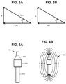
processor 140 may determine the depth of themagnetic target 120 by utilizing the z-component (HZ) of at least one of the digital magnetic compasses. As illustrated inFIG. 5A , the field strength (HX-Y) in the global X-Y plane is computed, the total field strength (HX-Y-Z) from all three sensors is computed, and the inverse tangent is computed to determine an angle (θ) of the magnetic target. - As illustrated in
FIG. 5B , the angle (θ) of the magnetic target is then used to determine the depth. Since the in-plane distance (dX-Y) to the magnetic target was previously determined, the depth (dZ) may be computed as the product of the in-plane distance and the tan(θ). - Expanding upon the example of
FIG. 4A , a depth for each in-plane distance of the line segments AP1, AP2, BP1, BP2, CP1, CP2, DP1 and DP2 is computed. Resulting is a total of eight depths. An average or other statistical measure of the depths may be computed to determine depth of themagnetic target 120. - Sensor measurements in the
array 130 may be affected by field effects due to the Earth's magnetic field or nearby iron. Theprocessor 140 may use measurements from an additional three-axis digital magnetic compass to compensate for these effects. The additional magnetic compass is located away frommagnetic target 120 so as not to sense the magnetic field frommagnetic target 120. For instance, the target's magnet field drops off exponentially such that it is nearly zero approximately eight inches from the central axis. Since the Earth's magnetic field is rather uniform, and iron effects due to large iron structures (e.g., due to steel in a building or an assembly jig) is also uniform, the additional digital compass will sense the a-, b- and c-components of this stray field only. These components may be transformed onto the local coordinate systems of each of the compasses and then subtracted from the respective components measured by the digital magnetic compasses. - The
apparatus 110 is not limited to a specific type ofmagnetic target 120. However, amagnetic target 120 having a cylindrical ferromagnetic core and a torroidal magnet surrounding the core is particularly beneficial. -
FIG. 6A is an illustration of an example of themagnetic target 120. Themagnetic target 120 ofFIG. 6 includes a cylindricalferromagnetic core 610 and atorroidal magnet 620 surrounding thecore 610. A ferromagnetic focusingcone 630 is disposed about thecore 610 and adjacent to thetorroidal magnet 620. The flux from themagnet 620 flows through the focusingcone 630 instead of surrounding air. In this manner, the focusingcone 630 focuses the magnetic field to improve flux density and uniformity of the field at the tip of the focusingcone 630. - As illustrated in
FIGS. 6A & 6B , theferromagnetic core 610 absorbs the magnetic field, and projects it axially to themagnet 620, thus aligning the magnetic field with the physical body of themagnet 620. This reduces error induced by misalignment. The high permeability of thecore 610 also helps to homogenize the magnetic field. - Reference is made to
FIG. 6C , which illustrates an example of components for themagnetic target 120 of FG. 6A. Thecore 610 and the focusingcone 630 form a unitary structure. Themagnet 620 slides onto thecore 610. Themagnetic target 120 further includes ahousing 640 andend cap 650. Thecore 610,magnet 620 and focusingcone 630 are enclosed within thehousing 640 andend cap 650. Thehousing 640 andend cap 650 may have the shape of a shear pin for insertion into a pilot hole. - The
core 610 may extend through an opening in theend cap 650. Aspring 660 within thehousing 640 may outwardly bias themagnet 620 towards theend cap 650. This spring-loaded configuration is advantageous for drilling and other operations wherein an object passes through the structure. For instance, themagnetic target 120 ofFIGS. 6A-6C may remain in a pilot hole while drilling is being performed. If the drill bit passes through and extends beyond the structure, the drill bit will depress thecore 610,magnet 620 and focusingcone 630. - The
apparatus 110 may be used manually. For example, theapparatus 110 may further include a hand tool (not shown), and thearray 130 andprocessor 140 may be integrated with the hand tool. The hand tool may be scanned across the front surface of a structure. Theprocessor 140 may send the offset vector and other information to a visual display on the tool. An operator can use this information to manually position the hand tool over themagnetic target 120. - However, due to automatic computation of the position of the
magnetic target 120 and computation of the offset vector, theapparatus 110 is especially suited for robotic operation. For example, a pair of robots may use theapparatus 110 to perform a manufacturing operation. -
FIG. 7 illustrates arobot system 710 for performing manufacturing operations on opposite sides of a non-magnetic wall (W). Therobot system 710 includes inner andouter robots inner robot 720 includes themagnetic target 120, which may be part of anend effector 722. Theinner robot 720 further includes apositioning system 724 for moving theend effector 722 along an inner surface of the wall (W) to position themagnetic target 120. Themagnetic target 120 may be held in position by theend effector 722 andpositioning system 724, or it may be secured to a feature at the inner surface of wall (W) (e.g., inserted in a hole in a part that is against the inner surface). - The
outer robot 730 includes theprocessor 140 and thearray 130. Thearray 130 may be part of anend effector 732. Theend effector 732 also includes amanufacturing tool 734. Theouter robot 730 further includes apositioning system 736 for moving theend effector 732 along an outer surface of the wall (W). The additional compass for measuring stray fields may also be carried on theouter robot 730. - The
array 130 may be integrated with themanufacturing tool 734. For instance, if themanufacturing tool 734 includes a drill, thearray 130 may be integrated in a spindle of the drill. -
FIG. 8 illustrates a method of using therobot system 710 to drill a hole through the wall (W) and into a blind pilot hole. The pilot hole is located in a part (not shown) on an inner side of the wall (W). As but one example, the wall (W) is formed by aircraft skin, and the part includes a stiffener located against an inner surface of the aircraft skin. The stiffener contains the pilot hole. - At
block 810, theinner robot 720 moves itsend effector 722 to insert themagnetic target 120 in the pilot hole. Atblock 820, theouter robot 730 located on an outer side of the wall (W) moves thearray 130 over an outer surface of the wall (W) to an expected position of the pilot hole. As a first example, theinner robot 720 is programmed to move itsend effector 722 over the expected position of the pilot hole, and theouter robot 730 is programmed to move itsend effector 732 over the expected position of the pilot hole. As a second example, theinner robot 720 moves itsend effector 722 from a current position to a second position at which themagnetic target 120 is placed in the pilot hole. Theinner robot 720 also determines a movement vector from the current position to the second position. Theinner robot 720 communicates the movement vector to theouter robot 730, and theouter robot 730 uses the movement vector to move itsend effector 732. - At
block 830, each digital magnetic compass of thearray 130 measures field strength of themagnetic target 120. Atblock 840, the measurements are compensated for the Earth's magnetic field and large iron effects. - At
block 850, theprocessor 140 computes locations of intersection points of direction vectors in the global X-Y plane. From these intersection points, the processor computes a position of themagnetic target 120 in the global X-Y plane. - At
block 860, theprocessor 140 computes an offset vector from the global position of themagnetic target 120 to a global position of a reference point. If the reference point corresponds to the centerline of a drill bit, the offset vector may indicate where the drill bit should be moved, or it may verify that the drill bit is directly over themagnetic target 120. - At
block 870, additional information such as depth and polarity of themagnetic target 120 may be computed. The magnetic target has north and south poles. When themagnetic target 120 is inserted in the pilot hole, one of the poles is closer to thearray 130 than the other one of the poles. Theprocessor 140 may determine the polarity of themagnetic target 120 by checking the polarity of the z-component of each of the digital magnetic compasses. - At
block 880, if the offset vector indicates that the distance between themagnetic target 120 and the reference point exceeds a threshold (that is, a location tolerance is exceeded), theouter robot 730 moves the reference point according to the offset vector. Blocks 830-880 may be repeated until the location tolerance is acceptable. - Once the location tolerance is acceptable, a manufacturing operation is performed (block 890). The drill bit is used to drill through the skin and into the pilot hole.
- Additional manufacturing operations may be performed. For example, after the hole has been drilled through the aircraft skin, the
inner robot 720 removes themagnetic target 120, theouter robot 730 inserts a fastener through the drilled hole, and theinner robot 720 terminates the fastener. - The information about the polarity may be used to determine whether a correct magnetic target is installed. Polarity information may also assist the manufacturing operation. Polarity information of different magnets may be used, for example, to signal a machine to use a different drill process (different drill speed, feed speed, peck cycle, etc), depending on the polarity seen by the
array 130. - The information about depth of the magnetic target may be used to determine depth of the drilling. If the
magnetic target 120 ofFIGS. 6A-6C is used, the depth measurement need not be precise, as the drill bit will displace the spring-biased magnet after drilling through the structure. - Further, the disclosure comprises embodiments according to the following clauses:
- Clause 1. Apparatus comprising:
- a magnetic target for generating a magnetic field that is uniform and concentric about a central axis of the target;
- an array of three-axis digital magnetic compasses for sensing the magnetic field; and
- a processor for finding intersection points of vectors from the compasses to the target, the vectors lying in a global X-Y plane that is normal to the central axis, each vector indicating a direction of sensed magnetic field from one of the compasses to the magnetic target.
- Clause 2. The apparatus of clause 1, wherein the intersection is derived from directions of the vectors but not magnitudes of the vectors.
- Clause 3. The apparatus of clause 1, wherein the processor uses the intersection points to derive a position of the magnetic target relative to the magnetic compasses in the global X-Y plane.
- Clause 4. The apparatus of clause 3, wherein the processor determines an offset vector from the target to a reference point.
- Clause 5. The apparatus of clause 3, wherein each digital magnetic compass includes magnetic sensors for sensing components of the magnetic field along local a-and b-axes, and wherein the components are transformed from the local a- and b-axes to the global X-Y plane.
- Clause 6. The apparatus of clause 3, wherein the processor
determines a direction vector for each compass;
determines the intersection points from the direction vectors; and
computes in-plane distances of the target from the intersection points. - Clause 7. The apparatus of clause 6, wherein the processor computes the position of the magnetic target as a statistical measure of the in-plane distances.
- Clause 8. The apparatus of clause 7, wherein the processor computes a statistical confidence measure of the in-plane distances.
- Clause 9. The apparatus of clause 6, wherein the processor calculates depth of the magnetic target using the in-plane distances and at least one z-component of magnetic strength.
- Clause 10. The apparatus of clause 1, wherein the array further includes an additional digital magnetic compass; and wherein the processor uses measurements from the additional compass to compensate for the Earth's magnetic field and iron effects.
- Clause 11. The apparatus of clause 1, wherein the magnetic target includes a cylindrical ferromagnetic core and a torroidal magnet surrounding the core.
- Clause 12. The apparatus of clause 11, wherein the magnetic target further includes a focusing cone about the core and adjacent to the torroidal magnet.
- Clause 13. The apparatus of clause 12, wherein magnetic target further includes a housing and a spring within the housing for outwardly biasing the torroidal magnet.
- Clause 14. A method of using the apparatus of clause 1 to perform a
manufacturing operation on a non-magnetic structure, the method comprising
from one side of the structure, positioning the magnetic target;
from an opposite side of the structure, moving the array over an expected position of the magnetic target;
using the processor to determine an offset vector between the magnetic target and a reference position;
moving the reference position according to the offset vector; and
performing the manufacturing operation on the structure after the reference position has been moved. - Clause 15. A robot system comprising first and second robots for performing a manufacturing operation on a non-magnetic structure,
the first robot including a magnetic target for generating a magnetic field that is uniform and concentric about a central axis of the target; and a first end effector and positioning system for positioning the magnetic target at a first side of the structure;
the second robot including a sensing array of three-axis digital magnetic compasses for sensing the magnetic field; a manufacturing tool; and a second end effector and positioning system for scanning the sensing array along a surface of a second, opposite side of the structure to locate the magnetic target;
the second robot further including a processor for finding intersection points of vectors from the compasses to the magnetic target, the vectors lying in a global X-Y plane, each vector indicating a direction of sensed magnetic field from one of the compasses to the target; the second robot using the intersection points to position the manufacturing tool with respect to the magnetic target. - Clause 16. A method comprising using the system of clause 15, wherein the first robot is used to position the target from the first side of the structure, and the second robot is used to move the array from the second side of the structure, and wherein the processor computes an offset vector for moving the tool over the magnetic target.
- Clause 17. The method of clause 16, further comprising determining polarity of the magnetic target, and using the polarity to perform the manufacturing operation.
- Clause 18 A magnetic target comprising a cylindrical ferromagnetic core; a torroidal magnet surrounding the core; and a focusing cone about the core and adjacent to the torroidal magnet.
- Clause 19 A method of locating a hidden feature behind a non-magnetic structure, the method comprising:
- placing a magnetic target at the feature;
- scanning a front of the structure using an array of three-axis digital magnetic compasses;
- computing a direction vector from each compass to the magnetic target, each direction vector lying in an X-Y plane that is normal to a centerline of the magnetic target;
- finding intersection points of the direction vectors; and
- using the intersection points to compute an offset vector from the target to a reference point, and using the offset vector to move the reference point.
- Clause 20. The method of clause 19, wherein the structure includes aircraft skin, wherein the hidden feature includes a pilot hole in a stiffener behind the aircraft skin; wherein the magnetic target is placed in the pilot hole; and wherein the array is scanned over the front of the aircraft skin.
- Still, information about depth may also be used to determine a drill cycle. Drilling to a desired depth instead of drilling past the depth can reduce cycle time.
Claims (15)
- Apparatus (110) comprising:a magnetic target (120) for generating a magnetic field that is uniform and concentric about a central axis of the target (120);an array (130) of three-axis digital magnetic compasses for sensing the magnetic field; anda processor (140) for finding intersection points of vectors from the compasses (210) to the target (120), the vectors lying in a global X-Y plane that is normal to the central axis, each vector indicating a direction of sensed magnetic field from one of the compassesto the magnetic target (120).
- The apparatus (110) of claim 1, wherein the intersection is derived from directions of the vectors but not magnitudes of the vectors.
- The apparatus (110) of claim 1, wherein the processor (140) uses the intersection points to derive a position of the magnetic target (120) relative to the magnetic compasses (210) in the global X-Y plane.
The apparatus (110) of claim 3, wherein the processor (140) determines an offset vector from the target (120) to a reference point; and wherein each digital magnetic compass (210) includes magnetic sensors for sensing components of the magnetic field along local a- and b-axes, and wherein the components are transformed from the local a- and b-axes to the global X-Y plane. - The apparatus (110) of claim 3, wherein the processor (140)
determines a direction vector for each compass (210);
determines the intersection points from the direction vectors;
computes in-plane distances of the target (120) from the intersection points; and
wherein the processor (140) computes the position of the magnetic target (120) as a statistical measure of the in-plane distances; and wherein the processor (140) computes a statistical confidence measure of the in-plane distances. - The apparatus (110) of claim 4, wherein the processor (140) calculates depth of the magnetic target (120) using the in-plane distances and at least one z-component of magnetic strength.
- The apparatus (110) of claim 1, wherein the array (130) further includes an additional digital magnetic compass (210); and wherein the processor (140) uses measurements from the additional compass to compensate for the Earth's magnetic field and iron effects.
- The apparatus (110) of claim 1, wherein the magnetic target (120) includes a cylindrical ferromagnetic core (610) and a torroidal magnet (620) surrounding the core (610); and wherein the magnetic target (120) further includes a focusing cone (630) about the core (610) and adjacent to the torroidal magnet (620).
- The apparatus (110) of claim 7, wherein magnetic target (120) further includes a housing (640) and a spring (660) within the housing (640) for outwardly biasing the torroidal magnet (620).
- A method of using the apparatus (110) of claim 1 to perform a manufacturing operation on a non-magnetic structure, the method comprising
from one side of the structure, positioning the magnetic target (120);
from an opposite side of the structure, moving the array over an expected position of the magnetic target (120);
using the processor (140) to determine an offset vector between the magnetic target (120) and a reference position;
moving the reference position according to the offset vector; and
performing the manufacturing operation on the structure after the reference position has been moved. - A robot system (710) comprising first and second robots (720, 730) for performing a manufacturing operation on a non-magnetic structure,
the first robot (720) including a magnetic target (120) for generating a magnetic field that is uniform and concentric about a central axis of the target; and a first end effector (722) and positioning system (724) for positioning the magnetic target (120) at a first side of the structure;
the second robot (730) including a sensing array (130) of three-axis digital magnetic compasses (210) for sensing the magnetic field; a manufacturing tool (734); and a second end effector and positioning system for scanning the sensing array along a surface of a second, opposite side of the structure to locate the magnetic target (120);
the second robot (730) further including a processor (140) for finding intersection points of vectors from the compasses to the magnetic target (120), the vectors lying in a global X-Y plane, each vector indicating a direction of sensed magnetic field from one of the compasses to the target; the second robot (730) using the intersection points to position the manufacturing tool (734) with respect to the magnetic target (120). - A method comprising using the system of claim 10, wherein the first robot (720) is used to position the target (120) from the first side of the structure, and the second robot (730) is used to move the array (130) from the second side of the structure, and wherein the processor (140) computes an offset vector for moving the tool over the magnetic target (120).
- The method of claim 11, further comprising determining polarity of the magnetic target (120), and using the polarity to perform the manufacturing operation.
- A magnetic target (120) comprising a cylindrical ferromagnetic core (610); a torroidal magnet (620) surrounding the core (610); and a focusing cone (630) about the core (610) and adjacent to the torroidal magnet (620).
- A method of locating a hidden feature behind a non-magnetic structure, the method comprising:placing a magnetic target (120) at the feature;scanning a front of the structure using an array of three-axis digital magnetic compassescomputing a direction vector from each compass to the magnetic target each direction vector lying in an X-Y plane that is normal to a centerline of the magnetic target (block 310)finding intersection points of the direction vectors (block 320); andusing the intersection points to compute an offset vector from the target to a reference point, and using the offset vector to move the reference point (blocks 330 and 340).
- The method of claim 14, wherein the structure includes aircraft skin, wherein the hidden feature includes a pilot hole in a stiffener behind the aircraft skin; wherein the magnetic target (120) is placed in the pilot hole; and wherein the array (130) is scanned over the front of the aircraft skin.
Applications Claiming Priority (1)
| Application Number | Priority Date | Filing Date | Title |
|---|---|---|---|
| US14/710,555 US11035672B2 (en) | 2015-05-12 | 2015-05-12 | Sensing of a magnetic target |
Publications (2)
| Publication Number | Publication Date |
|---|---|
| EP3093691A1 true EP3093691A1 (en) | 2016-11-16 |
| EP3093691B1 EP3093691B1 (en) | 2021-11-24 |
Family
ID=55527835
Family Applications (1)
| Application Number | Title | Priority Date | Filing Date |
|---|---|---|---|
| EP16159721.6A Active EP3093691B1 (en) | 2015-05-12 | 2016-03-10 | Sensing of a magnetic target |
Country Status (6)
| Country | Link |
|---|---|
| US (1) | US11035672B2 (en) |
| EP (1) | EP3093691B1 (en) |
| JP (1) | JP6786257B2 (en) |
| KR (1) | KR102488406B1 (en) |
| CN (1) | CN106152921B (en) |
| CA (1) | CA2924782C (en) |
Families Citing this family (9)
| Publication number | Priority date | Publication date | Assignee | Title |
|---|---|---|---|---|
| US10591627B2 (en) * | 2016-11-08 | 2020-03-17 | Frederick Energy Products, Llc | Managing vehicle movement in aisles by use of magnetic vectors |
| US10420999B2 (en) | 2017-03-27 | 2019-09-24 | Intel Corporation | Sensor-derived object flight performance tracking |
| US10831173B2 (en) * | 2017-08-11 | 2020-11-10 | The Boeing Company | Tool having magnetic material |
| CN107561462B (en) * | 2017-09-05 | 2024-09-13 | 重庆金山医疗技术研究院有限公司 | Capsule full-attitude measurement system based on changing magnetic field and space magnetic field detection device |
| EP3531151B1 (en) * | 2018-02-27 | 2020-04-22 | Melexis Technologies SA | Redundant sensor error reduction |
| CN109916287B (en) * | 2019-01-30 | 2020-11-27 | 西安维控自动化科技有限公司 | Planar displacement sensor based on magnetic induction, displacement detection method and system |
| WO2022174111A1 (en) * | 2021-02-12 | 2022-08-18 | Frederick Energy Products, Llc | Magnetic vector dynamics for managing vehicle movements |
| EP4215951A1 (en) * | 2022-01-21 | 2023-07-26 | PoleDetect Holding ApS | Locating device and system for detecting hidden objects in building constructions |
| US11872780B2 (en) | 2022-06-02 | 2024-01-16 | The Boeing Company | Methods and tool for cutting an uncured composite material |
Citations (7)
| Publication number | Priority date | Publication date | Assignee | Title |
|---|---|---|---|---|
| US1971189A (en) * | 1933-02-01 | 1934-08-21 | Gen Electric | Magnetic detector |
| WO1988002852A1 (en) * | 1986-10-17 | 1988-04-21 | K.G. Derman Aktiebolag | Method and device for locating concealed junction boxes |
| US5675488A (en) * | 1994-05-12 | 1997-10-07 | Halliburton Energy Services, Inc. | Location determination using vector measurements |
| US20030210027A1 (en) * | 2002-05-09 | 2003-11-13 | Pedigo Samuel F. | Control system and method for a magnetic indexer for high accuracy hole drilling |
| US20050052898A1 (en) * | 2003-09-05 | 2005-03-10 | Arntson Paul R. | Apparatus and methods for magnetic through-skin sensing |
| US20080048635A1 (en) * | 2002-08-19 | 2008-02-28 | Ab Electronic Limited | Method and Apparatus for Locating Non-Visible Objects |
| US20150003927A1 (en) * | 2013-06-28 | 2015-01-01 | The Boeing Company | Magnet sensing hole driller and method therefor |
Family Cites Families (12)
| Publication number | Priority date | Publication date | Assignee | Title |
|---|---|---|---|---|
| US5559432A (en) * | 1992-02-27 | 1996-09-24 | Logue; Delmar L. | Joystick generating a polar coordinates signal utilizing a rotating magnetic field within a hollow toroid core |
| US7608035B2 (en) * | 1996-09-10 | 2009-10-27 | Gradient Technologies, Llc | Method and morphologically adaptable apparatus for altering the charge distribution upon living membranes with functional stabilization of the membrane physical electrical integrity |
| GB0126014D0 (en) | 2001-10-30 | 2001-12-19 | Sensopad Technologies Ltd | Modulated field position sensor |
| US6651003B2 (en) * | 2001-07-30 | 2003-11-18 | Innovative Design Solutions, Inc. | Method of automatic continuous calibration for an electric compass |
| WO2004036147A2 (en) | 2002-10-16 | 2004-04-29 | Tt Electronics Technology Limited | Position sensing apparatus and method |
| GB2394293A (en) | 2002-10-16 | 2004-04-21 | Gentech Invest Group Ag | Inductive sensing apparatus and method |
| EP1774258A4 (en) | 2004-06-23 | 2008-12-17 | Fe Technical Services Inc | Capacitive sensing techniques |
| WO2006011276A1 (en) * | 2004-07-23 | 2006-02-02 | Yamaha Corporation | Direction processing device, direction processing method, direction processing program, direction measuring device, and geographic information display |
| EP1695783B1 (en) * | 2005-02-28 | 2008-04-16 | Siemens Aktiengesellschaft | Method for determining the position of an electrochemically drilled passage hole. |
| EP2018563B1 (en) * | 2006-05-10 | 2011-11-02 | Koninklijke Philips Electronics N.V. | A magnetic system for biosensors |
| US7782046B2 (en) * | 2007-02-05 | 2010-08-24 | General Electric Company | Electromagnetic tracking method and system |
| US8301302B2 (en) * | 2008-05-08 | 2012-10-30 | The Boeing Company | Synchronous robotic operation on a structure having a confined space |
-
2015
- 2015-05-12 US US14/710,555 patent/US11035672B2/en active Active
-
2016
- 2016-03-10 EP EP16159721.6A patent/EP3093691B1/en active Active
- 2016-03-18 KR KR1020160032472A patent/KR102488406B1/en active Active
- 2016-03-21 CA CA2924782A patent/CA2924782C/en active Active
- 2016-05-10 JP JP2016094293A patent/JP6786257B2/en active Active
- 2016-05-11 CN CN201610310756.5A patent/CN106152921B/en active Active
Patent Citations (7)
| Publication number | Priority date | Publication date | Assignee | Title |
|---|---|---|---|---|
| US1971189A (en) * | 1933-02-01 | 1934-08-21 | Gen Electric | Magnetic detector |
| WO1988002852A1 (en) * | 1986-10-17 | 1988-04-21 | K.G. Derman Aktiebolag | Method and device for locating concealed junction boxes |
| US5675488A (en) * | 1994-05-12 | 1997-10-07 | Halliburton Energy Services, Inc. | Location determination using vector measurements |
| US20030210027A1 (en) * | 2002-05-09 | 2003-11-13 | Pedigo Samuel F. | Control system and method for a magnetic indexer for high accuracy hole drilling |
| US20080048635A1 (en) * | 2002-08-19 | 2008-02-28 | Ab Electronic Limited | Method and Apparatus for Locating Non-Visible Objects |
| US20050052898A1 (en) * | 2003-09-05 | 2005-03-10 | Arntson Paul R. | Apparatus and methods for magnetic through-skin sensing |
| US20150003927A1 (en) * | 2013-06-28 | 2015-01-01 | The Boeing Company | Magnet sensing hole driller and method therefor |
Also Published As
| Publication number | Publication date |
|---|---|
| JP2017003573A (en) | 2017-01-05 |
| EP3093691B1 (en) | 2021-11-24 |
| US11035672B2 (en) | 2021-06-15 |
| CA2924782C (en) | 2020-03-24 |
| KR20160133359A (en) | 2016-11-22 |
| CN106152921A (en) | 2016-11-23 |
| KR102488406B1 (en) | 2023-01-12 |
| CA2924782A1 (en) | 2016-11-12 |
| US20160334212A1 (en) | 2016-11-17 |
| JP6786257B2 (en) | 2020-11-18 |
| CN106152921B (en) | 2020-06-02 |
Similar Documents
| Publication | Publication Date | Title |
|---|---|---|
| EP3093691B1 (en) | Sensing of a magnetic target | |
| CA2484180C (en) | Magnetic indexer for high accuracy hole drilling | |
| EP3650816B1 (en) | Magnetic position sensor system and method | |
| CN106141814B (en) | The detection of Digit Control Machine Tool translation shaft geometric error and discrimination method based on LaserTRACER | |
| EP3588011B1 (en) | Position sensor system and method, robust against disturbance field | |
| EP3735569B1 (en) | Magnetic field influence during rotation movement of magnetic target | |
| CN109883450B (en) | Positioning method of magnetic marker for detector in buried steel pipeline | |
| US8769838B2 (en) | Surveyor 's rod and magnetic locator | |
| CN106403873A (en) | Method for establishing workpiece measurement coordinate system based on curved surface benchmark | |
| CN109444773A (en) | A kind of magnetic source detection device of connected external magnets and array of magnetic sensors | |
| US11619759B2 (en) | Dipole locator using balanced antenna signals | |
| CN120384735A (en) | System and method for determining axial magnetic disturbance in a downhole directional sensor | |
| CN103353612A (en) | Measuring and positioning equipment and measuring and positioning method for underground target object | |
| CN211792262U (en) | Drilling device for circuit board | |
| KR20170092356A (en) | System for calibrating azimuth of 3-axis magnetic sensor | |
| TWI608243B (en) | Localization device and method using magnetic field | |
| WO2002097362A1 (en) | Photogrammetry targets | |
| JP2006226810A (en) | Azimuth measuring instrument | |
| Cui et al. | Three-axis magnetometer calibration based on optimal ellipsoidal fitting under constraint condition for pedestrian positioning system using foot-mounted inertial sensor/magnetometer | |
| CN107255461B (en) | Method for measuring the starting distance of the countersink edge of the drill-reaming-sinking integrated tool | |
| CN106017323A (en) | Hand-held measuring rod for collimating measurement reference points in hide position of supersize complex apparatus | |
| CN111504301A (en) | Positioning method, device and system based on magnetic field characteristic vector | |
| CN106908058B (en) | Method for determining aperture of geomagnetic positioning array | |
| JPH02222846A (en) | Measurement of magnetic field | |
| US10310080B2 (en) | Three dimensional manufacturing positioning system |
Legal Events
| Date | Code | Title | Description |
|---|---|---|---|
| PUAI | Public reference made under article 153(3) epc to a published international application that has entered the european phase |
Free format text: ORIGINAL CODE: 0009012 |
|
| 17P | Request for examination filed |
Effective date: 20160310 |
|
| AK | Designated contracting states |
Kind code of ref document: A1 Designated state(s): AL AT BE BG CH CY CZ DE DK EE ES FI FR GB GR HR HU IE IS IT LI LT LU LV MC MK MT NL NO PL PT RO RS SE SI SK SM TR |
|
| AX | Request for extension of the european patent |
Extension state: BA ME |
|
| RBV | Designated contracting states (corrected) |
Designated state(s): AL AT BE BG CH CY CZ DE DK EE ES FI FR GB GR HR HU IE IS IT LI LT LU LV MC MK MT NL NO PL PT RO RS SE SI SK SM TR |
|
| GRAP | Despatch of communication of intention to grant a patent |
Free format text: ORIGINAL CODE: EPIDOSNIGR1 |
|
| STAA | Information on the status of an ep patent application or granted ep patent |
Free format text: STATUS: GRANT OF PATENT IS INTENDED |
|
| RIC1 | Information provided on ipc code assigned before grant |
Ipc: G01V 3/08 20060101AFI20210316BHEP Ipc: G01V 15/00 20060101ALI20210316BHEP |
|
| INTG | Intention to grant announced |
Effective date: 20210408 |
|
| GRAJ | Information related to disapproval of communication of intention to grant by the applicant or resumption of examination proceedings by the epo deleted |
Free format text: ORIGINAL CODE: EPIDOSDIGR1 |
|
| STAA | Information on the status of an ep patent application or granted ep patent |
Free format text: STATUS: REQUEST FOR EXAMINATION WAS MADE |
|
| INTC | Intention to grant announced (deleted) | ||
| GRAP | Despatch of communication of intention to grant a patent |
Free format text: ORIGINAL CODE: EPIDOSNIGR1 |
|
| STAA | Information on the status of an ep patent application or granted ep patent |
Free format text: STATUS: GRANT OF PATENT IS INTENDED |
|
| INTG | Intention to grant announced |
Effective date: 20210625 |
|
| GRAS | Grant fee paid |
Free format text: ORIGINAL CODE: EPIDOSNIGR3 |
|
| GRAA | (expected) grant |
Free format text: ORIGINAL CODE: 0009210 |
|
| STAA | Information on the status of an ep patent application or granted ep patent |
Free format text: STATUS: THE PATENT HAS BEEN GRANTED |
|
| AK | Designated contracting states |
Kind code of ref document: B1 Designated state(s): AL AT BE BG CH CY CZ DE DK EE ES FI FR GB GR HR HU IE IS IT LI LT LU LV MC MK MT NL NO PL PT RO RS SE SI SK SM TR |
|
| REG | Reference to a national code |
Ref country code: GB Ref legal event code: FG4D |
|
| REG | Reference to a national code |
Ref country code: DE Ref legal event code: R096 Ref document number: 602016066503 Country of ref document: DE |
|
| REG | Reference to a national code |
Ref country code: AT Ref legal event code: REF Ref document number: 1450281 Country of ref document: AT Kind code of ref document: T Effective date: 20211215 |
|
| REG | Reference to a national code |
Ref country code: IE Ref legal event code: FG4D |
|
| REG | Reference to a national code |
Ref country code: LT Ref legal event code: MG9D |
|
| REG | Reference to a national code |
Ref country code: NL Ref legal event code: MP Effective date: 20211124 |
|
| REG | Reference to a national code |
Ref country code: AT Ref legal event code: MK05 Ref document number: 1450281 Country of ref document: AT Kind code of ref document: T Effective date: 20211124 |
|
| PG25 | Lapsed in a contracting state [announced via postgrant information from national office to epo] |
Ref country code: RS Free format text: LAPSE BECAUSE OF FAILURE TO SUBMIT A TRANSLATION OF THE DESCRIPTION OR TO PAY THE FEE WITHIN THE PRESCRIBED TIME-LIMIT Effective date: 20211124 Ref country code: LT Free format text: LAPSE BECAUSE OF FAILURE TO SUBMIT A TRANSLATION OF THE DESCRIPTION OR TO PAY THE FEE WITHIN THE PRESCRIBED TIME-LIMIT Effective date: 20211124 Ref country code: FI Free format text: LAPSE BECAUSE OF FAILURE TO SUBMIT A TRANSLATION OF THE DESCRIPTION OR TO PAY THE FEE WITHIN THE PRESCRIBED TIME-LIMIT Effective date: 20211124 Ref country code: BG Free format text: LAPSE BECAUSE OF FAILURE TO SUBMIT A TRANSLATION OF THE DESCRIPTION OR TO PAY THE FEE WITHIN THE PRESCRIBED TIME-LIMIT Effective date: 20220224 Ref country code: AT Free format text: LAPSE BECAUSE OF FAILURE TO SUBMIT A TRANSLATION OF THE DESCRIPTION OR TO PAY THE FEE WITHIN THE PRESCRIBED TIME-LIMIT Effective date: 20211124 |
|
| PG25 | Lapsed in a contracting state [announced via postgrant information from national office to epo] |
Ref country code: IS Free format text: LAPSE BECAUSE OF FAILURE TO SUBMIT A TRANSLATION OF THE DESCRIPTION OR TO PAY THE FEE WITHIN THE PRESCRIBED TIME-LIMIT Effective date: 20220324 Ref country code: SE Free format text: LAPSE BECAUSE OF FAILURE TO SUBMIT A TRANSLATION OF THE DESCRIPTION OR TO PAY THE FEE WITHIN THE PRESCRIBED TIME-LIMIT Effective date: 20211124 Ref country code: PT Free format text: LAPSE BECAUSE OF FAILURE TO SUBMIT A TRANSLATION OF THE DESCRIPTION OR TO PAY THE FEE WITHIN THE PRESCRIBED TIME-LIMIT Effective date: 20220324 Ref country code: PL Free format text: LAPSE BECAUSE OF FAILURE TO SUBMIT A TRANSLATION OF THE DESCRIPTION OR TO PAY THE FEE WITHIN THE PRESCRIBED TIME-LIMIT Effective date: 20211124 Ref country code: NO Free format text: LAPSE BECAUSE OF FAILURE TO SUBMIT A TRANSLATION OF THE DESCRIPTION OR TO PAY THE FEE WITHIN THE PRESCRIBED TIME-LIMIT Effective date: 20220224 Ref country code: NL Free format text: LAPSE BECAUSE OF FAILURE TO SUBMIT A TRANSLATION OF THE DESCRIPTION OR TO PAY THE FEE WITHIN THE PRESCRIBED TIME-LIMIT Effective date: 20211124 Ref country code: LV Free format text: LAPSE BECAUSE OF FAILURE TO SUBMIT A TRANSLATION OF THE DESCRIPTION OR TO PAY THE FEE WITHIN THE PRESCRIBED TIME-LIMIT Effective date: 20211124 Ref country code: HR Free format text: LAPSE BECAUSE OF FAILURE TO SUBMIT A TRANSLATION OF THE DESCRIPTION OR TO PAY THE FEE WITHIN THE PRESCRIBED TIME-LIMIT Effective date: 20211124 Ref country code: GR Free format text: LAPSE BECAUSE OF FAILURE TO SUBMIT A TRANSLATION OF THE DESCRIPTION OR TO PAY THE FEE WITHIN THE PRESCRIBED TIME-LIMIT Effective date: 20220225 Ref country code: ES Free format text: LAPSE BECAUSE OF FAILURE TO SUBMIT A TRANSLATION OF THE DESCRIPTION OR TO PAY THE FEE WITHIN THE PRESCRIBED TIME-LIMIT Effective date: 20211124 |
|
| PG25 | Lapsed in a contracting state [announced via postgrant information from national office to epo] |
Ref country code: SM Free format text: LAPSE BECAUSE OF FAILURE TO SUBMIT A TRANSLATION OF THE DESCRIPTION OR TO PAY THE FEE WITHIN THE PRESCRIBED TIME-LIMIT Effective date: 20211124 Ref country code: SK Free format text: LAPSE BECAUSE OF FAILURE TO SUBMIT A TRANSLATION OF THE DESCRIPTION OR TO PAY THE FEE WITHIN THE PRESCRIBED TIME-LIMIT Effective date: 20211124 Ref country code: RO Free format text: LAPSE BECAUSE OF FAILURE TO SUBMIT A TRANSLATION OF THE DESCRIPTION OR TO PAY THE FEE WITHIN THE PRESCRIBED TIME-LIMIT Effective date: 20211124 Ref country code: EE Free format text: LAPSE BECAUSE OF FAILURE TO SUBMIT A TRANSLATION OF THE DESCRIPTION OR TO PAY THE FEE WITHIN THE PRESCRIBED TIME-LIMIT Effective date: 20211124 Ref country code: DK Free format text: LAPSE BECAUSE OF FAILURE TO SUBMIT A TRANSLATION OF THE DESCRIPTION OR TO PAY THE FEE WITHIN THE PRESCRIBED TIME-LIMIT Effective date: 20211124 Ref country code: CZ Free format text: LAPSE BECAUSE OF FAILURE TO SUBMIT A TRANSLATION OF THE DESCRIPTION OR TO PAY THE FEE WITHIN THE PRESCRIBED TIME-LIMIT Effective date: 20211124 |
|
| REG | Reference to a national code |
Ref country code: DE Ref legal event code: R097 Ref document number: 602016066503 Country of ref document: DE |
|
| PLBE | No opposition filed within time limit |
Free format text: ORIGINAL CODE: 0009261 |
|
| STAA | Information on the status of an ep patent application or granted ep patent |
Free format text: STATUS: NO OPPOSITION FILED WITHIN TIME LIMIT |
|
| PG25 | Lapsed in a contracting state [announced via postgrant information from national office to epo] |
Ref country code: MC Free format text: LAPSE BECAUSE OF FAILURE TO SUBMIT A TRANSLATION OF THE DESCRIPTION OR TO PAY THE FEE WITHIN THE PRESCRIBED TIME-LIMIT Effective date: 20211124 Ref country code: AL Free format text: LAPSE BECAUSE OF FAILURE TO SUBMIT A TRANSLATION OF THE DESCRIPTION OR TO PAY THE FEE WITHIN THE PRESCRIBED TIME-LIMIT Effective date: 20211124 |
|
| REG | Reference to a national code |
Ref country code: CH Ref legal event code: PL |
|
| 26N | No opposition filed |
Effective date: 20220825 |
|
| PG25 | Lapsed in a contracting state [announced via postgrant information from national office to epo] |
Ref country code: SI Free format text: LAPSE BECAUSE OF FAILURE TO SUBMIT A TRANSLATION OF THE DESCRIPTION OR TO PAY THE FEE WITHIN THE PRESCRIBED TIME-LIMIT Effective date: 20211124 |
|
| REG | Reference to a national code |
Ref country code: BE Ref legal event code: MM Effective date: 20220331 |
|
| PG25 | Lapsed in a contracting state [announced via postgrant information from national office to epo] |
Ref country code: LU Free format text: LAPSE BECAUSE OF NON-PAYMENT OF DUE FEES Effective date: 20220310 Ref country code: LI Free format text: LAPSE BECAUSE OF NON-PAYMENT OF DUE FEES Effective date: 20220331 Ref country code: IE Free format text: LAPSE BECAUSE OF NON-PAYMENT OF DUE FEES Effective date: 20220310 Ref country code: CH Free format text: LAPSE BECAUSE OF NON-PAYMENT OF DUE FEES Effective date: 20220331 |
|
| PG25 | Lapsed in a contracting state [announced via postgrant information from national office to epo] |
Ref country code: BE Free format text: LAPSE BECAUSE OF NON-PAYMENT OF DUE FEES Effective date: 20220331 |
|
| PG25 | Lapsed in a contracting state [announced via postgrant information from national office to epo] |
Ref country code: IT Free format text: LAPSE BECAUSE OF FAILURE TO SUBMIT A TRANSLATION OF THE DESCRIPTION OR TO PAY THE FEE WITHIN THE PRESCRIBED TIME-LIMIT Effective date: 20211124 |
|
| P01 | Opt-out of the competence of the unified patent court (upc) registered |
Effective date: 20230516 |
|
| PG25 | Lapsed in a contracting state [announced via postgrant information from national office to epo] |
Ref country code: HU Free format text: LAPSE BECAUSE OF FAILURE TO SUBMIT A TRANSLATION OF THE DESCRIPTION OR TO PAY THE FEE WITHIN THE PRESCRIBED TIME-LIMIT; INVALID AB INITIO Effective date: 20160310 |
|
| PG25 | Lapsed in a contracting state [announced via postgrant information from national office to epo] |
Ref country code: MK Free format text: LAPSE BECAUSE OF FAILURE TO SUBMIT A TRANSLATION OF THE DESCRIPTION OR TO PAY THE FEE WITHIN THE PRESCRIBED TIME-LIMIT Effective date: 20211124 Ref country code: CY Free format text: LAPSE BECAUSE OF FAILURE TO SUBMIT A TRANSLATION OF THE DESCRIPTION OR TO PAY THE FEE WITHIN THE PRESCRIBED TIME-LIMIT Effective date: 20211124 |
|
| PG25 | Lapsed in a contracting state [announced via postgrant information from national office to epo] |
Ref country code: MT Free format text: LAPSE BECAUSE OF FAILURE TO SUBMIT A TRANSLATION OF THE DESCRIPTION OR TO PAY THE FEE WITHIN THE PRESCRIBED TIME-LIMIT Effective date: 20211124 |
|
| PG25 | Lapsed in a contracting state [announced via postgrant information from national office to epo] |
Ref country code: TR Free format text: LAPSE BECAUSE OF FAILURE TO SUBMIT A TRANSLATION OF THE DESCRIPTION OR TO PAY THE FEE WITHIN THE PRESCRIBED TIME-LIMIT Effective date: 20211124 |
|
| PGFP | Annual fee paid to national office [announced via postgrant information from national office to epo] |
Ref country code: GB Payment date: 20260327 Year of fee payment: 11 |
|
| PGFP | Annual fee paid to national office [announced via postgrant information from national office to epo] |
Ref country code: DE Payment date: 20260327 Year of fee payment: 11 |
|
| PGFP | Annual fee paid to national office [announced via postgrant information from national office to epo] |
Ref country code: FR Payment date: 20260325 Year of fee payment: 11 |