EP3093521A1 - Vibration damping device for vehicle body - Google Patents
Vibration damping device for vehicle body Download PDFInfo
- Publication number
- EP3093521A1 EP3093521A1 EP14877577.8A EP14877577A EP3093521A1 EP 3093521 A1 EP3093521 A1 EP 3093521A1 EP 14877577 A EP14877577 A EP 14877577A EP 3093521 A1 EP3093521 A1 EP 3093521A1
- Authority
- EP
- European Patent Office
- Prior art keywords
- piston
- valve
- hole
- vehicle body
- piston rod
- Prior art date
- Legal status (The legal status is an assumption and is not a legal conclusion. Google has not performed a legal analysis and makes no representation as to the accuracy of the status listed.)
- Granted
Links
Images


Classifications
-
- B—PERFORMING OPERATIONS; TRANSPORTING
- B60—VEHICLES IN GENERAL
- B60G—VEHICLE SUSPENSION ARRANGEMENTS
- B60G21/00—Interconnection systems for two or more resiliently-suspended wheels, e.g. for stabilising a vehicle body with respect to acceleration, deceleration or centrifugal forces
- B60G21/02—Interconnection systems for two or more resiliently-suspended wheels, e.g. for stabilising a vehicle body with respect to acceleration, deceleration or centrifugal forces permanently interconnected
- B60G21/06—Interconnection systems for two or more resiliently-suspended wheels, e.g. for stabilising a vehicle body with respect to acceleration, deceleration or centrifugal forces permanently interconnected fluid
- B60G21/073—Interconnection systems for two or more resiliently-suspended wheels, e.g. for stabilising a vehicle body with respect to acceleration, deceleration or centrifugal forces permanently interconnected fluid between wheels on the same axle but on different sides of the vehicle, i.e. the left and right wheel suspensions being interconnected
-
- F—MECHANICAL ENGINEERING; LIGHTING; HEATING; WEAPONS; BLASTING
- F16—ENGINEERING ELEMENTS AND UNITS; GENERAL MEASURES FOR PRODUCING AND MAINTAINING EFFECTIVE FUNCTIONING OF MACHINES OR INSTALLATIONS; THERMAL INSULATION IN GENERAL
- F16F—SPRINGS; SHOCK-ABSORBERS; MEANS FOR DAMPING VIBRATION
- F16F9/00—Springs, vibration-dampers, shock-absorbers, or similarly-constructed movement-dampers using a fluid or the equivalent as damping medium
- F16F9/06—Springs, vibration-dampers, shock-absorbers, or similarly-constructed movement-dampers using a fluid or the equivalent as damping medium using both gas and liquid
- F16F9/061—Mono-tubular units
-
- F—MECHANICAL ENGINEERING; LIGHTING; HEATING; WEAPONS; BLASTING
- F16—ENGINEERING ELEMENTS AND UNITS; GENERAL MEASURES FOR PRODUCING AND MAINTAINING EFFECTIVE FUNCTIONING OF MACHINES OR INSTALLATIONS; THERMAL INSULATION IN GENERAL
- F16F—SPRINGS; SHOCK-ABSORBERS; MEANS FOR DAMPING VIBRATION
- F16F9/00—Springs, vibration-dampers, shock-absorbers, or similarly-constructed movement-dampers using a fluid or the equivalent as damping medium
- F16F9/10—Springs, vibration-dampers, shock-absorbers, or similarly-constructed movement-dampers using a fluid or the equivalent as damping medium using liquid only; using a fluid of which the nature is immaterial
- F16F9/14—Devices with one or more members, e.g. pistons, vanes, moving to and fro in chambers and using throttling effect
- F16F9/16—Devices with one or more members, e.g. pistons, vanes, moving to and fro in chambers and using throttling effect involving only straight-line movement of the effective parts
- F16F9/18—Devices with one or more members, e.g. pistons, vanes, moving to and fro in chambers and using throttling effect involving only straight-line movement of the effective parts with a closed cylinder and a piston separating two or more working spaces therein
- F16F9/19—Devices with one or more members, e.g. pistons, vanes, moving to and fro in chambers and using throttling effect involving only straight-line movement of the effective parts with a closed cylinder and a piston separating two or more working spaces therein with a single cylinder and of single-tube type
-
- F—MECHANICAL ENGINEERING; LIGHTING; HEATING; WEAPONS; BLASTING
- F16—ENGINEERING ELEMENTS AND UNITS; GENERAL MEASURES FOR PRODUCING AND MAINTAINING EFFECTIVE FUNCTIONING OF MACHINES OR INSTALLATIONS; THERMAL INSULATION IN GENERAL
- F16F—SPRINGS; SHOCK-ABSORBERS; MEANS FOR DAMPING VIBRATION
- F16F9/00—Springs, vibration-dampers, shock-absorbers, or similarly-constructed movement-dampers using a fluid or the equivalent as damping medium
- F16F9/32—Details
- F16F9/44—Means on or in the damper for manual or non-automatic adjustment; such means combined with temperature correction
- F16F9/446—Adjustment of valve bias or pre-stress
-
- B—PERFORMING OPERATIONS; TRANSPORTING
- B60—VEHICLES IN GENERAL
- B60G—VEHICLE SUSPENSION ARRANGEMENTS
- B60G2206/00—Indexing codes related to the manufacturing of suspensions: constructional features, the materials used, procedures or tools
- B60G2206/01—Constructional features of suspension elements, e.g. arms, dampers, springs
Definitions
- the present invention relates to a vibration damping device for a vehicle body that damps the vibration of a vehicle body and improves a riding comfort.
- the body of a vehicle is known to be slightly elastically deformed by an external force applied at the time of traveling and, because of the elastic deformation, generate a vibration of a small amplitude.
- the amplitude of the vibration is several ten ⁇ m to about 1 to 2 mm.
- the external force that causes the elastic deformation is applied from the engine or the wheels running on an uneven road surface to the car body.
- a vibration damping device is mounted in a vehicle body in some cases.
- a conventional vibration damping device for a vehicle body for example, patent literature 1 describes a hydraulic device.
- the hydraulic vibration damping device for a vehicle body disclosed in patent literature 1 is formed from a hydraulic cylinder portion configured to generate a damping force and a connecting rod portion coupled with a piston rod projecting from the hydraulic cylinder portion.
- the hydraulic cylinder portion is mounted at, for example, one end of the vehicle body in the side-to-side direction.
- the distal end of the connecting rod portion is mounted on, for example, the other end of the vehicle body in the side-to-side direction.
- the hydraulic cylinder portion includes a hydraulic cylinder, a piston and a free piston that are movably fitted in the hydraulic cylinder, and a piston rod connected to the piston.
- the piston divides a hydraulic oil chamber in the hydraulic cylinder into two oil chambers.
- the piston is provided with a hydraulic oil passage that allows the two oil chambers to communicate with each other, and a check valve configured to open/close the hydraulic oil passage and generate a damping force.
- the piston rod extends through one oil chamber and projects outside the hydraulic cylinder.
- the free piston divides the inside of the hydraulic cylinder into a hydraulic oil chamber and a gas chamber filled with a high pressure gas.
- the hydraulic oil in the hydraulic oil chamber is always pressurized by the high pressure gas.
- the hydraulic cylinder portion itself is directly fixed to one end of the vehicle body in the side-to-side direction or the back-and-forth direction.
- the piston is fixed to the other end of the vehicle body in the side-to-side direction or the back-and-forth direction via the piston rod and the connecting rod.
- the piston and the hydraulic cylinder relatively move due to the vibration of the vehicle body, and the hydraulic oil passes the check valve of the piston, thereby generating a damping force.
- patent literature 2 describes a shock absorber.
- the shock absorber disclosed in patent literature 2 includes a cylinder, a piston rod inserted into one end of the cylinder, and a first piston and a second piston that are mounted on the piston rod.
- the first piston is fixed to the piston rod on the other end side of the cylinder.
- the second piston is fixed on the piston rod on one end side of the cylinder with respect to the first piston.
- the first piston and the second piston divide the inside of the cylinder into three oil chambers.
- the three oil chambers include a first oil chamber formed between the first piston and the other end of the cylinder, a second oil chamber between the two pistons, and a third oil chamber formed between the second piston and the one end of the cylinder.
- Each of the two pistons is provided with a leaf valve configured to generate a damping force.
- the leaf valve is provided in the hydraulic oil passage extending through the piston. The leaf valve closes when the pressure difference between the two oil chambers divided by the piston is equal to or smaller than a predetermined threshold, and opens when the pressure difference exceeds the threshold.
- a hydraulic oil passage that allows the second oil chamber and the third oil chamber to communicate with each other is formed in the piston rod.
- a needle valve that constitutes an adjustable valve is provided in the axis of the piston rod. The needle valve changes the sectional area of the hydraulic oil passage by a tapered portion fitted in the hydraulic oil passage in the piston rod.
- the needle value is integrated with an operation rod extending up to the projecting end of the piston rod. The operation rod threadably engages with the piston rod.
- the present inventor considers providing a damping force change mechanism capable of easily changing the damping force in an onboard state in the vibration damping device for a vehicle body as disclosed in patent literature 1.
- the damping force change mechanism described in patent literature 2 may be provided in the vibration damping device for a vehicle body.
- the threadably engaging portion of the needle valve is manually screwed or loosened.
- the seal pressure of the seal portion may vary on an operator basis depending on the degree of screwing. If the seal pressure is low, the hydraulic oil may leak from the gap between a through hole and the needle valve even if the needle valve is totally closed.
- the needle valve is always biased in the opening direction, and the risk of leakage is higher. Even slight leakage of the hydraulic oil results in a change in the damping force characteristic. That is, if the damping force change mechanism described in patent literature 2 is applied to the vibration damping device for a vehicle body disclosed in patent literature 1, the damping force characteristic may vary when closing the needle valve.
- the present invention has been made to solve the above-described problem, and has as its object to provide a vibration damping device for a vehicle body capable of easily changing the magnitude of a damping force and stabilizing the damping force characteristic in a case in which the damping force is large.
- a vibration damping device for a vehicle body comprising a cylinder having one end which is supported at a predetermined first mounting position of a vehicle body, a piston rod slidably extending through the other end of the cylinder, and having one end which is inserted into the cylinder and the other end which is supported at a predetermined second mounting position of the vehicle body, a first piston through which the piston rod extends, the first piston fixed to the one end of the piston rod and slidably fitted in the cylinder, a second piston through which the piston rod extends, the second piston fixed on the piston rod between the first piston and the other end of the cylinder and slidably fitted in the cylinder, a free piston slidably fitted between the first piston and the one end of the cylinder, a gas chamber formed between the free piston and the one end of the cylinder and filled with a gas of a predetermined pressure, a first oil chamber formed between the free piston and the first piston and filled with a hydraulic
- the magnitude of a damping force generated by the vibration damping device for a vehicle body is the sum of the magnitude of a damping force generated when the hydraulic oil passes through the first restrictor and the magnitude of a damping force generated when the hydraulic oil passes through the second restrictor.
- the third hydraulic oil passage that allows the first oil chamber and the second oil chamber to communicate with each other is formed in the piston rod.
- the hydraulic oil passes through the third hydraulic oil passage in place of the first restrictor and also passes through the second restrictor.
- a damping force is generated when the hydraulic oil passes through the second restrictor. That is, the magnitude of the damping force in this case is smaller than the magnitude of the damping force in the full close state of the on-off valve.
- the hydraulic oil in the first oil chamber and the second oil chamber is pressurized by the gas via the free piston.
- the oil pressure in the first oil chamber and that in the second oil chamber act on the on-off valve.
- the on-off valve is pressed in the axial direction by a force corresponding to the difference between the pressure receiving area on the first oil chamber side and the pressure receiving area on the second oil chamber side.
- the pressure receiving area on the second oil chamber side is smaller than the pressure receiving area on the first oil chamber side by an area corresponding to the shaft portion fitted in the through hole of the on-off valve. That is, the on-off valve is pressed from one end side of the piston rod to the other end side together with the operation rod whose other end is opened to the atmosphere.
- the damping force characteristic stabilizes in a state in which the on-off valve closes, and a large damping force is generated.
- a vibration damping device for a vehicle body capable of easily changing the magnitude of a damping force and stabilizing the damping force characteristic in a case in which the damping force is large.
- a vibration damping device for a vehicle body according to an embodiment of the present invention will now be described in detail with reference to Figs. 1 to 10 .
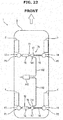
- a vehicle 1 shown in Fig. 1 is, for example, a passenger car that an occupant (not shown) drives to travel.
- a vehicle body 2 of the vehicle 1 is provided with a left-and-right pair of front wheels 3 and a left-and-right pair of rear wheels 4.
- the vehicle body 2 of this type is formed from a frameless body of, for example, a high-tensile steel plate.
- the vehicle body 2 elastically deforms according to an external force applied at the time of traveling and vibrates in, for example, the side-to-side and back-and-forth directions.
- Examples of the external force that generates the vibration are a force applied to the vehicle body 2 when the front wheels 3 and the rear wheels 4 run on an uneven spot and a force received from a vibrating engine (not shown).
- the vehicle 1 includes a first vibration damping device 11 for a vehicle body provided in the front portion of the vehicle body 2 and a second vibration damping device 12 for a vehicle body provided in the rear portion of the vehicle body 2.
- Identical devices can be used as the first vibration damping device 11 for a vehicle body and the second vibration damping device 12 for a vehicle body.
- each of the first vibration damping device 11 for a vehicle body and the second vibration damping device 12 for a vehicle body is mounted at a predetermined first mounting position P1 of the vehicle body 2 and supported, and the other end is mounted at a predetermined second mounting position P2 and supported. Note that even if the first mounting position P1 and the second mounting position P2 have a difference of elevation, the same effect can be obtained.
- the first mounting position P1 and the second mounting position P2 can be the upper ends of a left-and-right pair of suspension towers 13 and 14 as part of a suspension system, as shown in Fig. 1 . That is, one end (the end on the left side of the vehicle body) of each of the first vibration damping device 11 for a vehicle body and the second vibration damping device 12 for a vehicle body according to this embodiment is mounted on the suspension tower 13 located on the left side of the vehicle body. The other end is mounted on the suspension tower 14 located on the right side of the vehicle body. Note that the suspension towers 13 and 14 shown in Fig. 1 are illustrated not at the actual positions but behind the front wheels 3 or the rear wheels 4.
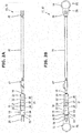
- Each of the first vibration damping device 11 for a vehicle body and the second vibration damping device 12 for a vehicle body is formed by connecting a plurality of parts.
- the plurality of parts are, for example, a hydraulic damper 15 located on one end side (the left side in Fig. 1 ) in the longitudinal direction, an extension joint 16 located on the other end side, and an operation device 17 placed between these parts.
- the operation device 17 is used to change the magnitude of the damping force generated by the vibration damping devices 11 and 12.
- the hydraulic damper 15, the extension joint 16, and the operation device 17 are connected in a state in which they are arranged in the longitudinal direction, and details will be described later.
- these members are arranged on the same axis.
- One end of the hydraulic damper 15 is formed from a hydraulic cylinder 18 (to be described later), as shown in Figs. 2A and 2B .
- This one end is the end mounted on the suspension tower 13 on the left side of the vehicle body.
- One end of the hydraulic cylinder 18 is mounted at the first mounting position P1 (the suspension tower 13 on the left side of the vehicle body) and supported.
- the other end of the hydraulic damper 15 is formed from a piston rod 19 (to be described later).
- the piston rod 19 slidably extends through the other end of the hydraulic cylinder 18.
- One end of the piston rod 19 is inserted into the hydraulic cylinder 18.
- the other end of the piston rod 19 is supported at the second mounting position P2 (the suspension tower 14 on the right side of the vehicle body) via the operation device 17 and the extension joint 16.
- the hydraulic cylinder 18 includes an oil chamber 21 filled with an hydraulic oil, and is formed by mounting a lid member 23 and a guide member 24 in a cylinder tube 22 made of a cylinder.
- the lid member 23 forms one end of the hydraulic cylinder 18, and blocks one end (the left end in Figs. 2A and 2B ) of the cylinder tube 22.
- the guide member 24 forms the other end of the hydraulic cylinder 18, and blocks the other end of the cylinder tube 22 and simultaneously slidably supports the piston rod 19.
- the lid member 23 is fitted in the cylinder tube 22 and welded to the cylinder tube 22 in this state.
- a mounting member 25 that is formed to have a U-shaped section is welded to the lid member 23.
- the mounting member 25 is fixed, by a fixing bolt (not shown), to a mounting bracket 26 (see Fig. 2B ) provided on the upper end of the suspension tower 13 located on the left side of the vehicle body.
- the upper end of the suspension tower 14 located on the right side of the vehicle body is connected, via the mounting bracket 26 provided there, to the mounting member 25 on the side of the extension joint 16.
- each of the first vibration damping device 11 for a vehicle body and the second vibration damping device 12 for a vehicle body is mounted on the suspension towers 13 and 14 via the mounting members 25 and the mounting brackets 26.
- Each mounting bracket 26 is formed with a rigidity that transmits the vibration of the vehicle body 2 to the side of the hydraulic cylinder 18.
- the vibration damping device for a vehicle body according to the present invention also includes a device provided with a rigid structure capable of transmitting a vibration between the first mounting position P1 and the second mounting position P2.
- the guide member 24 is fitted in the other end of the cylinder tube 22 and fixed to the cylinder tube 22 by circlips 28 and 29 together with a first spring seat 27.
- Seal members 30 configured to seal the portion that the piston rod 19 extends through are provided on the two ends of the guide member 24.
- the seal members 30 include a first seal member 30a and a second seal member 30b which are located on the side of the oil chamber 21, and a third seal member 30c located outside the oil chamber 21.
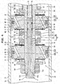
- a first piston 31, a second piston 32, and a free piston 33 are slidably fitted in the cylinder tube 22.
- These pistons 31 to 33 are formed to have a circular section that is slidably fitted in the cylinder tube 22.
- the first piston 31 and the second piston 32 according to this embodiment are identical.
- the first piston 31 is fixed to one end of the piston rod 19 together with a plurality of parts to be described later.
- the second piston 32 is fixed between the first piston 31 and the guide member 24 (the other end of the hydraulic cylinder 18) in the piston rod 19 together with a plurality of parts to be described later.
- the free piston 33 is arranged between the first piston 31 and the lid member 23 (one end of the hydraulic cylinder 18), as shown in Figs. 2A and 2B .
- the free piston 33 divides the interior of the hydraulic cylinder 18 into the oil chamber 21 and a gas chamber 34.
- An O-ring 35 is mounted on the outer surface of the free piston 33. The O-ring 35 seals the portion between the gas chamber 34 and the oil chamber 21.
- the gas chamber 34 is filled with N 2 gas of a predetermined pressure. For this reason, the hydraulic oil in the oil chamber 21 is pressurized by the free piston 33.
- the first piston 31 divides the oil chamber 21 into a first oil chamber 36 and a second oil chamber 37.
- the first oil chamber 36 is formed between the free piston 33 and the first piston 31.
- the second piston 32 divides the oil chamber 21 into the second oil chamber 37 and a third oil chamber 38.
- the second oil chamber 37 is formed between the first piston 31 and the second piston 32.
- the third oil chamber 38 is formed between the second piston 32 and the guide member 24 (the other end of the hydraulic cylinder 18).
- a bearing 39 and an O-ring 40 are provided on the outer surface of each of the first piston 31 and the second piston 32.
- the bearing 39 smoothens the slide between the first piston 31 or the second piston 32 and the cylinder tube 22.
- the O-ring 40 biases the bearing 39 outward in the radial direction so as to increase the diameter, and also seals the gap between the inner surface of the bearing 39 and outer surface of the first piston 31 or the second piston 32.
- the first piston 31 is provided with a first hydraulic oil passage 41 including an tension-side passage 41A and a compression-side passage 41B.
- the second piston 32 is provided with a second hydraulic oil passage 42 including an tension-side passage 42A and a compression-side passage 42B.
- the tension-side passages 41A and 42A and the compression-side passages 41B and 42B are provided with valve bodies 45 to 48 of a first leaf valve mechanism 43 and a second leaf valve mechanism 44, and details will be described later.
- the valve bodies 45 to 48 are configured to regulate the hydraulic oil flowing direction to one direction.
- the portions where the tension-side passages 41A and 42A and the compression-side passages 41B and 42B extend through the first piston 31 and the second piston 32 include a plurality of portions alternately provided at appropriate intervals in the circumferential direction of the first piston 31 and the second piston 32.
- the end of the tension-side passage 41A of the first piston 31 on the side of the first oil chamber 36 is formed from an annular first concave portion 49.
- the end of the compression-side passage 41B of the first piston 31 on the side of the second oil chamber 37 is formed from an annular second concave portion 50.
- the end of the tension-side passage 42A of the second piston 32 on the side of the second oil chamber 37 is formed from an annular third concave portion 51.
- the end of the compression-side passage 42B of the second piston 32 on the side of the third oil chamber 38 is formed from an annular fourth concave portion 52.
- the piston rod 19 extends through the axes of the first piston 31 and the second piston 32.
- the piston rod 19 includes a large diameter portion 19a that extends through the guide member 24, and a small diameter portion 19b connected to one end of the large diameter portion 19a.
- the first piston 31, the second piston 32, and other parts to be described later are overlaid in the axial direction and fasted to the small diameter portion 19b by a fixing nut 53.
- a second spring seat 54, a first spacer 55, and the valve body 48 of the second leaf valve mechanism 44 to be described later are provided on the small diameter portion 19b between the second piston 32 and the large diameter portion 19a sequentially from the side of the large diameter portion.
- the valve body 47 of the second leaf valve mechanism 44, a second spacer 56, a communicating member 57, a third spacer 58, and the valve body 46 of the first leaf valve mechanism 43 are provided between the second piston 32 and the first piston 31 sequentially from the side of the second piston 32.
- the valve body 45 of the first leaf valve mechanism 43, a fourth spacer 59, and a washer 60 are provided between the first piston 31 and the fixing nut 53 sequentially from the side of the first piston 31.
- the first spacer 55, the second spacer 56, the third spacer 58, and the fourth spacer 59 are identical.
- the second spring seat 54 located between the second piston 32 and the large diameter portion 19a of the piston rod 19 is configured to receive the spring force of a compression coil spring 61.
- the compression coil spring 61 is inserted between the second spring seat 54 and the first spring seat 27 located on the side of the guide member 24 in a compressed state.
- the piston rod 19 extends through the center of the compression coil spring 61.
- the first piston 31 and the second piston 32 are biased by the spring force of the compression coil spring 61 in a direction (leftward in Fig. 3 ) in which the hydraulic damper 15 is contracted.
- the compression coil spring 61 is configured to cancel the force (gas reaction force) in the axial direction, which acts on the piston rod 19 due to the pressure receiving area difference between the two surfaces of the first piston 31.
- the force in the axial direction is generated because the pressure receiving area of the first piston 31 on the side of the second oil chamber 37 is smaller than the pressure receiving area on the side of the first oil chamber 36.
- the first piston 31 is pressed by the force in the axial direction in a direction in which the hydraulic damper 15 expands.
- the free length of the hydraulic damper 15 is the length in a state in which the above-described force in the axial direction is canceled by the spring force of the compression coil spring 61 and kept in balance.
- the spring force of the compression coil spring 61 is adjusted such that the free length matches the mounting size in the vehicle body 2.
- the hydraulic damper 15 can expand/contract in fast response and generate a damping force.
- the first leaf valve mechanism 43 provided on the first piston 31 and the second leaf valve mechanism 44 provided on the second piston 32 are similar to those used in a shock absorber for a suspension system in a vehicle or the like.
- the first leaf valve mechanism 43 and the second leaf valve mechanism 44 are identical.
- the first leaf valve mechanism 43 is formed from the first hydraulic oil passage 41 (the tension-side passage 41A and the compression-side passage 41B) of the first piston 31, and the valve bodies 45 and 46 that cover the first concave portion 49 and the second concave portion 50, respectively.
- the second leaf valve mechanism 44 is formed from the second hydraulic oil passage 42 (the tension-side passage 42A and the compression-side passage 42B) of the second piston 32, and the valve bodies 47 and 48 that cover the third concave portion 51 and the fourth concave portion 52, respectively.
- the valve body 45 forms a check valve that closes the first concave portion 49 of the first piston 31.
- the valve body 46 forms a check valve that closes the second concave portion 50 of the first piston 31.
- the valve body 47 forms a check valve that closes the third concave portion 51 of the second piston 32.
- the valve body 48 forms a check valve that closes the fourth concave portion 52 of the second piston 32.
- first leaf valve mechanism 43 forms a "first restrictor” of the present invention
- second leaf valve mechanism 44 forms a "second restrictor” of the present invention
- Each of the valve bodies 45 to 48 is formed from a plurality of disc-shaped plates.
- the valve bodies 45 to 48 are mounted on the piston rod 19 in a state in which they are pressed against the outer peripheries of the concave portions 49 to 52 by the spring forces of their own. That is, the inner surfaces of the valve bodies 45 to 48 are pressed to the piston side by the first spacer 55, the second spacer 56, the third spacer 58, and the fourth spacer 59 provided on the piston rod 19 when the fixing nut 53 is fastened.
- valve bodies 45 to 48 deform when the inner surfaces are pressed to the piston side, and are pressed against the outer peripheries of the concave portions 49 to 52 under a predetermined initial load.
- valve body 45 of the first piston 31 blocks the opening portion of the tension-side passage 41A on the side of the first oil chamber 36 under the predetermined initial load.
- the valve body 45 opens when the oil pressure in the second oil chamber 37 is higher than the initial load of the valve body 45.
- the valve body 46 of the first piston 31 blocks the opening portion of the compression-side passage 41B on the side of the second oil chamber 37 under the predetermined initial load.
- the valve body 46 opens when the oil pressure in the first oil chamber 36 is higher than the initial load of the valve body 46.
- the valve body 47 of the second piston 32 blocks the opening portion of the tension-side passage 42A on the side of the second oil chamber 37 under the predetermined initial load.
- the valve body 47 opens when the oil pressure in the third oil chamber 38 is higher than the initial load of the valve body 47.
- the valve body 48 of the second piston 32 blocks the opening portion of the compression-side passage 42B on the side of the third oil chamber 38 under the predetermined initial load.
- the valve body 48 opens when the oil pressure in the second oil chamber 37 is higher than the initial load of the valve body 48.
- the thickness and the number of valve bodies 45 to 48 are determined based on the magnitude of the damping force to be generated by the hydraulic damper 15. When the spring force of the valve bodies 45 to 48 becomes large, the generated damping force becomes large.
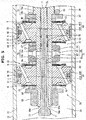
- the communicating member 57 provided between the first piston 31 and the second piston 32 is formed into a ring shape fitted on the piston rod 19. As shown in Figs. 4 and 5 , an annular groove 62 extending in the circumferential direction is formed in the inner surface of the communicating member 57. A plurality of first small holes 63 radially extending through the communicating member 57 are formed in the bottom portion of the annular groove 62.
- a plurality of second small holes 64 radially extending through the piston rod 19 are formed in a portion where the communicating member 57 is fitted on the piston rod 19.
- the plurality of second small holes 64 allow a through hole 65 formed in the axis of the piston rod 19 to communicate with the outside (the annular groove 62 of the communicating member 57) of the piston rod 19. That is, the through hole 65 in the piston rod 19 communicates with the second oil chamber 37 via a communicating hole 66 formed from the first small holes 63, the annular groove 62, and the second small holes 64.
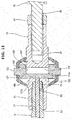
- the through hole 65 of the piston rod 19 forms part of a damping force change mechanism 70 that selectively allows the first oil chamber 36 and the second oil chamber 37 to communicate with each other. As shown in Figs. 3 to 5 and 9 , the through hole 65 opens to the end face of one end of the piston rod 19 and extends toward the other end of the piston rod 19.
- the damping force change mechanism 70 includes the through hole 65, an on-off valve 71 provided in the through hole 65, and the like.
- the on-off valve 71 opens/closes one end of the through hole 65. In a state in which the on-off valve 71 is open, the first oil chamber 36 and the second oil chamber 37 are allowed to communicate with each other by a third hydraulic oil passage 72 formed from part of the through hole 65 and the above-described communicating hole 66.
- the on-off valve 71 is formed from a poppet valve inserted in the through hole 65 of the piston rod 19, as shown in Figs. 4 , 5 , and 7 .
- the on-off valve 71 includes a shaft portion 73 slidably fitted in the through hole 65, and an expanded diameter portion 74 provided at one end of the shaft portion 73.
- the shaft portion 73 is formed from a sliding portion 73a located at an end on the opposite side of the expanded diameter portion 74, and a small diameter portion 73b located between the sliding portion 73a and the expanded diameter portion 74.
- the sliding portion 73a is formed into a columnar shape and slidably fitted in the through hole 65.
- Two O-rings 75 are mounted on the sliding portion 73a.
- the O-rings 75 seal portions between the through hole 65 and the sliding portion 73a.
- An end face 73c (see Fig. 7 ) facing an operation rod 77 of an operation mechanism 76 (to be described later) is formed at an end of the sliding portion 73a on the opposite side of the expanded diameter portion 74.
- the diameter of the small diameter portion 73b is smaller than the diameter of the through hole 65.
- a space S between the small diameter portion 73b and the hole wall of the through hole 65 forms part of the above-described third hydraulic oil passage 72.
- the small diameter portion 73b has a length to locate the sliding portion 73a on the side of the second piston 32 (the right side in Fig. 4 ) with respect to the second small holes 64 of the piston rod 19 in a state in which the expanded diameter portion 74 abuts against one end face 19c of the piston rod 19.
- the expanded diameter portion 74 forms the valve body of the poppet valve.
- the expanded diameter portion 74 projects from the through hole 65 to the first oil chamber 36 and extends outward in the radial direction of the piston rod 19.
- An opening portion 65a of the through hole 65 is formed into a tapered shape that gradually increases the diameter toward the first oil chamber 36.
- the edge of the opening portion 65a with the maximum diameter corresponds to the opening edge of the through hole 65.
- the tapered opening portion 65a forms part of the end face 19c of the piston rod 19.
- the expanded diameter portion 74 is formed into a disc shape having a tapered portion 74a fitted in the opening portion 65a.
- the diameter of the expanded diameter portion 74 is larger than that of the opening portion 65a and smaller than that of the small diameter portion 19b of the piston rod 19. That is, the expanded diameter portion 74 is formed into a shape capable of facing the whole opening edge of the through hole 65 and tightly contacting the one end face 19c of the piston rod 19.
- the on-off valve 71 changes to a full close state. In the full close state, the expanded diameter portion 74 tightly contacts the whole edge of the opening portion 65a of the through hole 65. As shown in Fig. 5 , when the expanded diameter portion 74 separates from the piston rod 19 and wholly enters the first oil chamber 36, the on-off valve 71 changes to a full open state. In the full open state, the through hole 65 opens to the first oil chamber 36, and the first oil chamber 36 and the second oil chamber 37 communicate with each other via the third hydraulic oil passage 72.
- a direction in which the on-off valve 71 moves toward the first oil chamber 36 will be referred to as a first direction
- a direction (a direction in which the on-off valve 71 moves to the other end of the piston rod 19) reverse to the first direction will be referred to as a second direction. That is, when the on-off valve 71 moves in the first direction, the third hydraulic oil passage 72 formed from part (the space S formed between the shaft portion 73 and the hole wall of the through hole 65) of the through hole 65 and the communicating hole 66 is opened. On the other hand, when the on-off valve 71 moves in the second direction, the expanded diameter portion 74 blocks the through hole 65, and the third hydraulic oil passage 72 is closed.
- the hydraulic oil in the first oil chamber 36 and the hydraulic oil in the second oil chamber 37 are pressurized by the gas pressure via the free piston 33. For this reason, the oil pressure in the first oil chamber 36 and the oil pressure in the second oil chamber 37 act on the on-off valve 71.
- the on-off valve 71 is pressed by the oil pressure in the second direction in both the full close state shown in Fig. 4 and the full open state shown in Fig. 5 . This is because the pressure receiving area of the on-off valve 71 on the side of the first oil chamber 36 and the pressure receiving area on the side of the second oil chamber 37 have a difference.
- the on-off valve 71 is pressed in the axial direction by a force corresponding to the pressure receiving area difference.
- the pressure receiving area of the on-off valve 71 on the side of the second oil chamber 37 is smaller than the pressure receiving area on the side of the first oil chamber 36 by an area corresponding to the shaft portion 73 (the shaft portion fitted in the through hole 65) of the on-off valve 71. That is, in a state in which a pressing force is not applied from the operation mechanism 76 (to be described later) to the shaft portion 73, the on-off valve 71 according to this embodiment is maintained in the full close state by the pressure in the gas chamber 34.
- the operation mechanism 76 is configured to determine the moving direction of the on-off valve 71 via the operation rod 77 facing the on-off valve 71.
- the operation rod 77 is inserted on the side of the other end of the piston rod 19 with respect to the on-off valve 71 in the through hole 65 so as to be movable in the first direction and the second direction.
- One end of the operation rod 77 contacts the end face 73c of the shaft portion 73.
- the other end (the end on the opposite side of the on-off valve 71) of the operation rod 77 is connected to the operation device 17, as shown in Figs. 8 and 9 .
- an atmospheric pressure acts on the other end of the operation rod 77.
- the operation device 17 includes a support member 81 that forms a housing, and an operation member 82 pivotally supported by the support member 81.
- the support member 81 is threadably mounted on the other end of the piston rod 19, and also threadably mounted on one end of the extension joint 16. That is, the support member 81 is placed between the extension joint 16 and the other end of the piston rod 19.
- the threadably mounted portion between the piston rod 19 and the support member 81 employs a structure in which a male screw 83 formed on the piston rod 19 threadably engages with a female screw 84 of the support member 81, as shown in Fig. 9 .
- the threadably mounted portion between the extension joint 16 and the support member 81 employs a structure in which a male screw 85 formed on the extension joint 16 threadably engages with a female screw 86 of the support member 81.
- a lock nut 87 threadably engages with the male screw 85.
- the total length of each of the vibration damping devices 11 and 12 can be adjusted by changing the screwing amount of the male screw 85 and thus fastening the lock nut 87.
- a first stopper 81a and a second stopper 81b which are configured to define the operation range of the operation member 82 (to be described later are provided on an upper surface of the support member 81.
- Each of the first stopper 81a and the second stopper 81b is formed by making part of an upper surface 81c of the support member 81 project with respect to the remaining portion.
- Symbols 81d and 81e indicating the operation positions of the operation member 82 are provided on the upper surface 81c of the support member 81 with the first stopper 81a and the second stopper 81b.
- the symbol 81d is H of the alphabet
- the symbol 81e is S of the alphabet.
- the symbols 81d and 81e are formed at positions on one and the other sides in a direction perpendicular to the longitudinal direction of the support member 81.
- the operation member 82 is formed from an operation element 88 manually operable by the passenger, and a cam 89 that pivots integrally with the operation element 88.
- the operation member 82 converts a pivotal motion into a reciprocating motion and transmits it to the operation rod 77.
- the operation element 88 is formed from a shaft 90 pivotally supported by the support member 81, and a handle 91 mounted on the shaft 90.
- the axial direction of the shaft 90 is perpendicular to the axial direction of the piston rod 19.
- the pivotal motion of the handle 91 is regulated when it abuts against the first stopper 81a or the second stopper 81b described above.
- the shaft 90 is formed from a large diameter portion 90a having a disc shape, and a small diameter portion 90b connected to the axis of the large diameter portion 90a.
- the large diameter portion 90a is pivotally fitted in a large diameter hole 92 of the support member 81.
- the depth of the large diameter hole 92 is larger than the thickness of the large diameter portion 90a.
- the large diameter portion 90a is connected to the through hole 65 of the piston rod 19 by a communicating hole 93.
- the small diameter portion 90b is pivotally fitted in a small diameter hole 94 of the support member 81.
- the distal end of the small diameter portion 90b projects to the outside of the support member 81.
- O-rings 95 configured to seal portions with respect to the support member 81 are mounted on the outer surface of the large diameter portion 90a and the outer surface of the small diameter portion 90b.
- the handle 91 is fixed, by a fixing screw 96, to the end of the small diameter portion 90b projecting to the outside of the support member 81.
- the cam 89 is formed from a disc having an eccentricity with respect to the shaft 90 when viewed from the axial direction of the shaft.
- the cam 89 is inserted into the large diameter hole 92 of the support member 81 in a state in which the small diameter portion 90b of the shaft 90 extends through the cam 89, and is fixed to the small diameter portion 90b by a fixing screw 97. That is, the cam 89 is formed to partially project outward in the radial direction from the small diameter portion 90b of the shaft 90.
- the operation rod 77 is inserted from the through hole 65 of the piston rod 19 into the large diameter hole 92 via the communicating hole 93 of the support member 81.
- the operation rod 77 contacts the outer surface of the cam 89 as a cam face in a state in which the operation rod 77 serves as a cam follower.
- the thus formed cam 89 converts the pivotal motion of the shaft 90, which occurs when the handle 91 is operated, into a reciprocating motion and transmits it to the other end of the operation rod 77.
- the cam 89 In a state in which one end of the handle 91 is located near the above-described symbol 81d that is H of the alphabet and abuts against the first stopper 81a, the cam 89 is located at a first position H indicated by a broken line in Fig. 8 . In this state, the pressing amount of the operation rod 77 by the cam 89 is minimized.
- the first position H indicates a state in which a projecting portion 89a of the cam 89 is located on the opposite side of the operation rod 77.
- the cam 89 In a state in which one end of the handle 91 is located near the above-described symbol 81e that is S of the alphabet and abuts against the second stopper 81b, the cam 89 is located at a second position S as indicated by an alternate long and two short dashed line in Fig. 8 .
- the cam 89 pivots to the second position S indicated by the alternate long and two short dashed line in Fig. 8 , the on-off valve 71 moves in the first direction and changes to the full open state.
- the second position S is a position at which the projecting portion 89a of the cam 89 presses the operation rod 77 by a predetermined amount. In this embodiment, when the shaft 90 rotates by about 90°, the cam 89 moves between the first position H and the second position S.
- the gaps capable of leaking the hydraulic oil are gaps through which the hydraulic oil can flow among the first to third oil chambers 36 to 38.
- the gaps capable of leaking the hydraulic oil will be referred to as leak portions hereinafter.
- the leak portions in the hydraulic damper 15 according to this embodiment are first leak portions within ranges indicated by alternate long and two short dashed lines A in Fig. 4 and second leak portions within ranges indicated by alternate long and two short dashed lines B in Fig. 4 .
- the first leak portions indicated by the alternate long and two short dashed lines A will simply be referred to as leak portions A
- the second leak portions indicated by the alternate long and two short dashed lines B will simply be referred to as leak portions B hereinafter.
- the first leak portions A are gaps as the clearances between the cylinder tube 22 and the first piston 31 and the second piston 32.
- the second leak portions B are the gaps between the valve bodies 45 to 48 of the first leaf valve mechanism 43 and the second leaf valve mechanism 44 and the outer peripheries of the concave portions 49 to 52 of the first piston 31 and the second piston 32.
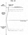
- the hydraulic oil is viscous. For this reason, immediately after the first piston 31 and the second piston 32 start moving and before the valve bodies 45 to 48 open, the hydraulic oil leaks through the first leak portions A and the second leak portions B, thereby generating a damping force in a magnitude corresponding to the magnitude of the viscous resistance of the hydraulic oil.
- the magnitude of the damping force immediately after the first piston 31 and the second piston 32 start moving changes almost in proportion to the moving speed of the first piston 31 and the second piston 32, as shown in Fig. 10 .
- the damping force based on the viscous resistance of the hydraulic oil will simply be referred to as a low-speed damping force hereinafter.
- the piston speed of the first piston 31 and the second piston 32 after the start of moving changes from a leak range L1 where the low-speed damping force is generated to a transition range L2 and then to a valve range L3, as indicated by a solid line in Fig. 10 .
- the transition range L2 is a speed range where the valve bodies 45 to 48 start opening.
- the valve range L3 is a speed range where a predetermined damping force is generated by the first leaf valve mechanism 43 and the second leaf valve mechanism 44.
- the piston speed changes from the transition range L2 to the valve range L3, and accordingly, the hydraulic oil passes through the first leaf valve mechanism 43 and the second leaf valve mechanism 44.
- the magnitude of the damping force generated by the first vibration damping device 11 for a vehicle body and the second vibration damping device 12 for a vehicle body in this case is the sum of the magnitude of the damping force generated when the hydraulic oil passes through the first leaf valve mechanism 43 and the magnitude of the damping force generated when the hydraulic oil passes through the second leaf valve mechanism 44.
- the on-off valve 71 when the on-off valve 71 is open, the first oil chamber 36 and the second oil chamber 37 communicate with each other via the third hydraulic oil passage 72. For this reason, the hydraulic oil does not pass through the leak portion A and the leak portion B of the first piston 31 and the first leaf valve mechanism 43. That is, in this case, the hydraulic oil does not pass through the leak portion A and the leak portion B of the second piston 32 and the second leaf valve mechanism 44.
- the damping force (low-speed damping force) is generated in a magnitude corresponding to the magnitude of the viscous resistance of the hydraulic oil because the hydraulic oil leaks through the leak portion A and the leak portion B of the second piston 32.
- the magnitude of the low-speed damping force in this case is the same as that in a case in which the on-off valve 71 is closed. This is because the magnitude of the viscous resistance of the hydraulic oil depends on the minimum sectional area of the passage when the hydraulic oil leaks through the leak portion A or the leak portion B. The minimum sectional area does not change between a state in which the on-off valve 71 is closed and a state in which the on-off valve 71 is open. For this reason, the low-speed damping force does not change between a state in which the on-off valve 71 is closed and a state in which the on-off valve 71 is open.
- the hydraulic oil passes through the second leaf valve mechanism 44, thereby generating a damping force. That is, as indicated by a broken line in Fig. 10 , the magnitude of the damping force generated by the first vibration damping device 11 for a vehicle body and the second vibration damping device 12 for a vehicle body in this case is smaller than the magnitude of the damping force in a case in which the on-off valve 71 is closed, which is indicated by a solid line, in both the tension damping force and the compression damping force.
- the tension damping force is a damping force generated when the hydraulic damper 15 expands.
- the compression damping force is a damping force generated when the hydraulic damper 15 contracts.
- the on-off valve 71 is biased in the second direction (closing direction) by the oil pressure.
- the oil pressure that biases the on-off valve 71 is the oil pressure in the first oil chamber 36 and the second oil chamber 37, whose pressure source is the gas in the gas chamber 34, and is based on the difference of the pressure receiving area of the on-off valve 71.
- a vibration damping device for a vehicle body capable of easily changing the magnitude of the damping force and stabilizing the damping force characteristic in a case in which the damping force is large.
- the on-off valve 71 is formed from a poppet valve including the shaft portion 73 slidably fitted in the through hole 65, and the expanded diameter portion 74 provided at one end of the shaft portion 73.
- the first direction is the direction in which the on-off valve 71 moves toward the first oil chamber 36.
- the space S formed between the shaft portion 73 and the hole wall of the through hole 65 and the third hydraulic oil passage 72 formed from the communicating hole 66 are opened.
- the expanded diameter portion 74 blocks the through hole 65, and the third hydraulic oil passage 72 is closed.
- the on-off valve 71 is closed as it is pressed by the oil pressure in the first oil chamber 36 and that in the second oil chamber 37 based on the pressure receiving area difference between the two surfaces of the expanded diameter portion 74.
- the first vibration damping device 11 for a vehicle body and the second vibration damping device 12 for a vehicle body can properly prevent the hydraulic oil from leaking from the on-off valve 71 in the full close state because the seal pressure in the full close state of the on-off valve 71 is constant.
- a damping force characteristic as designed can be attained when the hydraulic oil passes through the first leaf valve mechanism 43 and the second leaf valve mechanism 44, a stable high-performance vibration damping device for a vehicle body can be provided.
- Each of the vibration damping devices 11 and 12 includes the support member 81 mounted on the other end of the piston rod 19, and the operation member 82 pivotally supported by the support member 81.
- the operation member 82 converts a pivotal motion into a reciprocating motion and transmits it to the operation rod 77.
- the operation rod 77 advances in the first direction or retreats in the second direction as it is pressed by the on-off valve 71. That is, when the operation member 82 is operated, the position of the operation rod 77 changes, and the aperture ratio of the on-off valve 71 changes.
- the on-off valve 71 formed from a poppet valve can be operated by the operation member 82 at a position close to the piston rod 19, the first vibration damping device 11 for a vehicle body and the second vibration damping device 12 for a vehicle body including the operation devices 17 can be made compact.
- the degree of freedom for the installation position is high.
- the operation member 82 includes the operation element 88 pivotally supported by the support member 81, and the cam 89 that pivots integrally with the operation element 88.
- the cam 89 contacts the operation rod 77 in a state in which the operation rod 77 serves as a cam follower.
- the operation element 88 pivots with respect to the support member 81 together with the cam 89, the operation rod 77 moves, and the aperture ratio of the on-off valve 71 formed from a poppet valve increases or decreases.
- the state of the on-off valve 71 can quickly be switched from the full close state to the full open state or from the full open state to the full close state.
- a vibration damping device for a vehicle body capable of quickly and smoothly switching between a mode in which a relatively large damping force is generated and a mode in which a relatively small damping force is generated.
- the support member 81 is placed between the other end of the piston rod 19 and the extension joint 16 that extends from the second mounting position P2 to the piston rod 19.
- the support member 81 is arranged on the same axis as the piston rod 19. Hence, according to this embodiment, it is possible to provide a more compact vibration damping device for a vehicle body including the operation device 17.
- the operation device can be formed as shown in Fig. 11 .
- the same reference numerals as described with reference to Figs. 1 to 10 denote the same or similar members in Fig. 11 , and a detailed description thereof will appropriately be omitted.
- the support member 81 of the operation device 17 shown in Fig. 11 is formed into a columnar shape long in the axial direction of the piston rod 19.
- the piston rod 19 is threadably mounted on one end of the support member 81, and the extension joint 16 is threadably mounted on the other end.
- a through hole 101 extending in the radial direction of the support member 81 is formed, and a stopper pin 81f stands.
- the through hole 101 has an elliptic opening long in the axial direction of the piston rod 19 when viewed from the opening side of the through hole 101.
- the through hole 101 is connected to the through hole 65 of the piston rod 19 via a communicating hole 101a.
- the stopper pin 81f is configured to regulate the movement of an operation element 103 to be described later, and located on the opposite side of the piston rod 19 with respect to the through hole 101.
- An end of the operation rod 77 projects from the piston rod 19, and is inserted into the through hole 101 via the communicating hole 101a.
- a rod-shaped connecting member 102 is mounted at the end of the operation rod 77.
- the connecting member 102 is inserted into the through hole 101 while extending in the direction (the vertical direction in Fig. 11 ) in which the through hole 101 extends through the support member 81.
- the connecting member 102 is also fitted in the through hole 101 to be movable in the axial direction of the piston rod 19. The two ends of the connecting member 102 project from the through hole 101.
- the operation element 103 is connected to the projecting end of the connecting member 102.
- the connecting member 102 reciprocates between an advance position shown in Fig. 11 and a retreat position spaced rightward apart from the advance position in Fig. 11 in accordance with the movement of the operation element 103.
- the advance position is a position at which the connecting member 102 contacts a hole wall 101b of the through hole 101 on the side of the piston rod 19.
- the retreat position is a position at which the movement of the operation element 103 is regulated by the stopper pin 81f.
- the connecting member 102 is biased rightward in Fig. 11 by the gas reaction force transmitted to the operation rod 77 and is always in contact with the operation element 103.
- the operation element 103 is formed into an annular shape capable of receiving the support member 81.
- the outer periphery of the operation element 103 is provided with a cover 104 that is made of rubber and covers the opening portion of the through hole 101 and a screw portion to be described later.
- a female screw 106 threadably engaging with a male screw 105 of the support member 81 and an annular groove 107 engaging with the connecting member 102 are formed are formed in the inner surface of the operation element 103.
- the annular groove 107 opens inward in the radial direction of the operation element 103 having an annular shape and to one side of the axial direction pointing the hydraulic cylinder 18.
- the on-off valve 71 changes to the full open state.
- the on-off valve 71 closes when the threadably engaging portion between the operation element 103 and the support member 81 is loosened, and the operation rod 77 and the connecting member 102 are pressed by the gas reaction force and follow the operation element 103.
- the on-off valve 71 changes to the full close state.
- the aperture ratio of the on-off valve 71 changes.
- the aperture ratio of the on-off valve 71 formed from a poppet valve can finely be adjusted by the screw. It is therefore possible to change the damping force characteristic of the first vibration damping device 11 for a vehicle body and the second vibration damping device 12 for a vehicle body using the on-off valve 71 as an adjustable valve.
- An on-off valve and an operation mechanism can be formed as shown in Figs. 12 to 18 .
- the same reference numerals as described with reference to Figs. 1 to 11 denote the same or similar members in Figs. 12 to 18 , and a detailed description thereof will appropriately be omitted.
- a vibration damping device for a vehicle body according to this embodiment is different from the vibration damping device for a vehicle body described in the first embodiment only in the on-off valve and the operation mechanism.
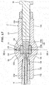
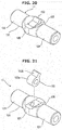
- An on-off valve 111 shown in Fig. 12 is of a rotation type that pivots with respect to an axis C of a piston rod 19 as the center.
- the on-off valve 111 includes a shaft portion 112 inserted into a through hole 65 of the piston rod 19, and an expanded diameter portion 113 provided at one end of the shaft portion 112.
- the shaft portion 112 is formed from a columnar portion 112a having a columnar shape and located on the axis of a second piston 32, and a tubular portion 112b having a cylindrical shape with a closed end and formed between the columnar portion 112a and the expanded diameter portion 113.
- the columnar portion 112a and the tubular portion 112b are fitted in the through hole 65 to be slidable in the circumferential direction.
- a plurality of O-rings 114 are mounted on the outer surface of the columnar portion 112a to seal portions between the columnar portion 112a and the hole wall surface of the through hole 65.
- An operation rod 115 is formed integrally with the columnar portion 112a. As shown in Fig. 17 , the operation rod 115 projects from the other end of the piston rod 19 and is connected to an operation device 17 to be described later.
- the tubular portion 112b is slidably fitted on the hole wall surface of the through hole 65 all the way in the longitudinal direction. Note that the clearance between the tubular portion 112b and the hole wall surface is formed to be wider than the clearance between the columnar portion 112a and the hole wall surface. The clearances are made different to make the resistance at the time of pivot of the on-off valve 111 as small as possible.
- Third small holes 116 configured to allow the inside of the tubular portion 112b to communicate with second small holes 64 of the piston rod 19 are formed at an end of the tubular portion 112b adjacent to the columnar portion 112a. As shown in Fig. 13 , the second small holes 64 are formed at two points of the piston rod 19 in the circumferential direction. The two second small holes 64 according to this embodiment are formed at positions spaced apart by 180° in the circumferential direction. The third small holes 116 are formed into a shape radially extending through the tubular portion 112b.
- the third small holes 116 are located at the same positions as the second small holes 64 in the axial direction of the piston rod 19.
- the on-off valve 111 is formed into such a shape that locates the second small holes 64 and the third small holes 116 at the same positions in the axial direction of the piston rod 19 in a state in which the expanded diameter portion 113 abuts against one end face 19c of the piston rod 19.
- a hollow portion 117 of the tubular portion 112b is formed by drilling the shaft portion 112 from the expanded diameter portion 113. One end of the hollow portion 117 opens to a first oil chamber 36.
- the on-off valve 111 rotates to a position at which the third small holes 116 are connected to the second small holes 64, thereby connecting the hollow portion 117, the third small holes 116, the second small holes 64, an annular groove 62, and first small holes 63.
- the position of the on-off valve 111 in the rotation direction at which the third small holes 116 are connected to the second small holes 64 will be referred to as a "full open position" hereinafter.
- the first oil chamber 36 and a second oil chamber 37 communicate with each other via a third hydraulic oil passage 119 including the oil hole 118 formed from the hollow portion 117 and the third small holes 116 and the communicating hole 66 extending from the second small holes 64 to the first small holes 63 via the annular groove 62.
- the on-off valve 111 pivots between the full open position shown in Fig. 13 and a full close position shown in Fig. 14 .
- the full close position is a position at which the third small holes 116 (the openings of the oil hole 118) are blocked by the hole wall surface of the through hole 65. That is, when the on-off valve 111 rotates from the full close position shown in Fig. 14 in the first direction clockwise in Fig. 14 , the third hydraulic oil passage 119 formed from the oil hole 118 and the communicating hole 66 is opened.
- the on-off valve 111 rotates from the full open position shown in Fig. 13 in the second direction counterclockwise in Fig.
- the first direction is the direction indicated by an arrow A in Fig. 14
- the second direction is the direction indicated by an arrow B in Fig. 13 .
- the expanded diameter portion 113 is formed from a ring-shaped plate.
- the hole at the center of the expanded diameter portion 113 is the opening portion of the hollow portion 117 described above.
- the outer diameter of the expanded diameter portion 113 is smaller than the outer diameter of the one end face 19c of the piston rod 19, as shown in Fig. 12 .
- the one end face 19c of the piston rod 19 according to this embodiment is an annular flat surface perpendicular to the axis C of the piston rod 19. That is, the expanded diameter portion 113 according to this embodiment is also formed into a shape that faces the entire opening edge of the through hole 65 and can tightly contact the one end face 19c of the piston rod 19.
- the on-off valve 111 is pressed to the side of the other end of the piston rod 19 when the oil pressure in the first oil chamber 36 and that in the second oil chamber 37 are applied to the expanded diameter portion 113 and the tubular portion 112b.
- the expanded diameter portion 113 is pressed toward the shaft portion 112 based on the pressure receiving area difference.
- the tubular portion 112b is pressed when the pressure of the hydraulic oil in the hollow portion 117 is applied to the inner bottom surface.
- the on-off valve 111 is held in a state in which the expanded diameter portion 113 is always in tight contact with the piston rod 19.
- the hydraulic oil can be prevented from leaking from a gap corresponding to the clearance between the tubular portion 112b and the hole wall surface of the through hole 65.
- the operation device 17 includes a support member 121 placed between the piston rod 19 and an extension joint 16, and an operation element 122 pivotally supported by the support member 121.
- the support member 121 is formed from cylindrical portions 123 and 124 located at the two ends, and a pair of arms 125 that connect the cylindrical portions to each other.
- One cylindrical portion 123 out of the two cylindrical portions 123 and 124 is threadably mounted on the other end of the piston rod 19.
- the other cylindrical portion 124 is threadably mounted on the extension joint 16.
- a drive shaft 126 is provided inside the pair of arms 125 between the cylindrical portions 123 and 124, as shown in Figs. 17 and 18 .
- the drive shaft 126 is formed from a small diameter portion 126a and a large diameter portion 126b, and pivotally supported by the support member 121 in a state in which the drive shaft 126 is located on the same axis as the piston rod 19.
- the small diameter portion 126a of the drive shaft 126 is formed to be longer than the large diameter portion 126b in the axial direction and arranged between the arms 125.
- a pair of planes 127 are formed at the distal end of the small diameter portion 126a.
- the planes 127 extend in parallel to the axis of the piston rod 19 and face each other while sandwiching the axis located at the center.
- a plate-shaped connecting piece 128 formed at an end of the operation rod 115 is fitted between the planes 127 to be movable in the axial direction of the piston rod 19. That is, the operation rod 115 pivots integrally with the drive shaft 126 in a state in which a movement in the axial direction with respect to the drive shaft 126 is permitted.
- a boss portion 122a of the operation element 122 is mounted on the small diameter portion 126a of the drive shaft 126 in a fitted state.
- the operation element 122 is formed from the boss portion 122a through which the small diameter portion 126a extends, and a lever 122b projecting from the boss portion 122a.
- the boss portion 122a is fixed to the small diameter portion 126a by a fixing bolt 129. That is, the operation element 122 pivots with respect to the support member 121 about the axis of the piston rod 19 together with the drive shaft 126.
- the operation rod 115 pivots together with the on-off valve 111.
- the operation device 17 includes a click mechanism 131 to determine the position of the operation element 122 in the rotation direction.
- the click mechanism 131 is formed from two concave portions 132 and 133 formed in the outer surface of the boss portion 122a, a ball 134 held by the arm 125 of the support member 121, and a compression coil spring 135 that biases the ball 134 toward the boss portion 122a.
- the ball 134 and the compression coil spring 135 are inserted in a through hole 136 formed in the arm 125.
- the compression coil spring 135 is inserted in a state in which the compression coil spring 135 is compressed between the ball 134 and a plug 137 press-fitted in the opening portion of the through hole 136.
- the click mechanism 131 regulates the rotation of the operation element 122 in both a state in which the ball 134 engages with one concave portion 132, as shown in Fig. 19 , and a state in which the ball 134 engages with the other concave portion 133.
- the on-off valve 111 when the ball 134 engages with one concave portion 132, as shown in Fig. 19 , the on-off valve 111 changes to the full open state.
- the lever 122b moves to a position indicated by an alternate long and two short dashed line in Fig. 19 , and the ball 134 engages with the other concave portion 133, the on-off valve 111 changes to the full close state.
- the rotation angle of the operation element 122 necessary for the on-off valve 111 to change from the full open state to the full close state is set to about 75°.
- a first vibration damping device 11 for a vehicle body and a second vibration damping device 12 for a vehicle body each including the on-off valve 111 with the above arrangement and an operation mechanism 76
- the on-off valve 111 rotates to the full close position shown in Fig. 14
- the third hydraulic oil passage 119 closes, and therefore, a relatively large damping force is generated.
- the hydraulic oil flows to the third hydraulic oil passage 119 but not to a first leaf valve mechanism 43, and therefore, a relatively small damping force is generated.
- the on-off valve 111 is pressed by the oil pressure in the first oil chamber 36 and that in the second oil chamber 37, and the expanded diameter portion 113 tightly contacts the one end face 19c of the piston rod 19. For this reason, the hydraulic oil passage formed from the gap corresponding to the clearance between the tubular portion 112b of the on-off valve 111 and the hole wall surface of the through hole 65 of the piston rod 19 is closed by the expanded diameter portion 113.
- the on-off valve 111 opens/closes by pivoting. For this reason, the full close state of the on-off valve 111 can correctly be implemented based on the position in the rotation direction without an influence of the magnitude of the operation force. It is therefore possible to properly prevent the hydraulic oil from leaking from the on-off valve 111 in the full close state.
- a damping force characteristic as designed can be attained when the hydraulic oil passes through the first leaf valve mechanism 43 and a second leaf valve mechanism 44, a high-performance vibration damping device for a vehicle body can be provided.
- Each of the first vibration damping device 11 for a vehicle body and the second vibration damping device 12 for a vehicle body includes the support member 121 mounted on the other end of the piston rod 19, and the operation element 122 connected to the operation rod 115 in a state in which they pivot integrally.
- the operation element 122 is supported by the support member 121 to freely pivot in the first direction and the second direction.
- the on-off valve 111 can be made to pivot and opened/closed using the operation element 122. For this reason, since the rotation-type on-off valve 111 can be operated by the operation element 122 at a position close to the piston rod 19, the first vibration damping device 11 for a vehicle body and the second vibration damping device 12 for a vehicle body including the operation devices 17 can be made compact. Hence, when installing the first vibration damping device 11 for a vehicle body and the second vibration damping device 12 for a vehicle body in the vehicle body, the degree of freedom for the installation position is high.
- the support member 121 according to this embodiment is placed between the other end of the piston rod 19 and the extension joint 16. For this reason, since the support member 121 is arranged on the same axis as the piston rod 19 and the extension joint 16, it is possible to provide a more compact vibration damping device for a vehicle body including the operation device 17.
- FIG. 22 An operation mechanism used to operate an on-off valve can be formed as shown in Fig. 22 .
- the same reference numerals as described with reference to Figs. 1 to 21 denote the same or similar members in Fig. 22 , and a detailed description thereof will appropriately be omitted.
- a vibration damping device for a vehicle body according to this embodiment is different from the vibration damping device for a vehicle body described in the first embodiment only in the operation mechanism.
- An operation element 141 of an operation mechanism 76 shown in Fig. 22 is a pivot-type handle as shown in Figs. 8 and 9 or a pivot-type lever as shown in Fig. 19 .
- One end of an operation wire 142 is connected to the operation element 141.
- the other end of the operation wire 142 is connected to an input member 143 spaced apart from a first mounting position P1 or a second mounting position P2 of the vehicle body.
- the input member 143 can be arranged in the room of the vehicle or in the engine room or luggage room.
- the input member 143 can be arranged within a range easy to reach for the passenger, and an on-off valve 71 or 111 can be operated by remote control.
- an on-off valve 71 or 111 can be operated by remote control.
- FIG. 23 An operation mechanism used to operate an on-off valve can be formed as shown in Fig. 23 .
- the same reference numerals as described with reference to Figs. 1 to 21 denote the same or similar members in Fig. 23 , and a detailed description thereof will appropriately be omitted.
- a vibration damping device for a vehicle body according to this embodiment is different from the vibration damping device for a vehicle body described in the first embodiment only in the operation mechanism.
- An operation device 17 shown in Fig. 23 includes an electric actuator 151.
- the actuator 151 is connected to an operation element 152 of the operation device 17 and moves the operation element 152 between a position at which an on-off valve 71 or 111 is set in a full open state and a position at which the on-off valve 71 or 111 is set in a full close state.
- a screw-type actuator as shown in Fig. 11 can be used in addition to a pivot-type handle as shown in Figs. 8 and 9 and a pivot-type lever as shown in Fig. 19 .
- the actuator 151 is connected to a switch 153 operated by the passenger, and operates when the switch 153 is operated.
- the switch 153 can be arranged in the room of the vehicle or in the engine room or luggage room.
- the on-off valve 71 or 111 when the passenger operates the switch 153, the on-off valve 71 or 111 is opened/closed by the power of the actuator 151. Hence, in this embodiment as well, the on-off valve 71 or 111 can be operated by remote control. It is therefore possible to provide a vibration damping device for a vehicle body with the on-off valve 71 or 111 easy to operate.
- the on-off valve 71 formed from a poppet valve or the rotation-type on-off valve 111 driven by the actuator 151 maintains the full close state without application of an operation force. That is, the on-off valve 71 formed from a poppet valve is biased in the second direction based on the pressure receiving area difference by the oil pressure in a first oil chamber 36 and that in a second oil chamber 37 and held in the full close state.
- the rotation-type on-off valve 111 is not rotated by the oil pressure because the operation direction and the direction in which the oil pressure acts are different.
- the on-off valve 111 is held at the full close position by the frictional resistance between an expanded diameter portion 113 and one end face 19c of a piston rod 19.
Abstract
Description
- The present invention relates to a vibration damping device for a vehicle body that damps the vibration of a vehicle body and improves a riding comfort.
- The body of a vehicle is known to be slightly elastically deformed by an external force applied at the time of traveling and, because of the elastic deformation, generate a vibration of a small amplitude. The amplitude of the vibration is several ten µm to about 1 to 2 mm. The external force that causes the elastic deformation is applied from the engine or the wheels running on an uneven road surface to the car body.
- Conventionally, to damp a vehicle body vibration of this type, a vibration damping device is mounted in a vehicle body in some cases. As a conventional vibration damping device for a vehicle body, for example,
patent literature 1 describes a hydraulic device. - The hydraulic vibration damping device for a vehicle body disclosed in
patent literature 1 is formed from a hydraulic cylinder portion configured to generate a damping force and a connecting rod portion coupled with a piston rod projecting from the hydraulic cylinder portion. The hydraulic cylinder portion is mounted at, for example, one end of the vehicle body in the side-to-side direction. The distal end of the connecting rod portion is mounted on, for example, the other end of the vehicle body in the side-to-side direction. - The hydraulic cylinder portion includes a hydraulic cylinder, a piston and a free piston that are movably fitted in the hydraulic cylinder, and a piston rod connected to the piston.
- The piston divides a hydraulic oil chamber in the hydraulic cylinder into two oil chambers. The piston is provided with a hydraulic oil passage that allows the two oil chambers to communicate with each other, and a check valve configured to open/close the hydraulic oil passage and generate a damping force. The piston rod extends through one oil chamber and projects outside the hydraulic cylinder.
- The free piston divides the inside of the hydraulic cylinder into a hydraulic oil chamber and a gas chamber filled with a high pressure gas. The hydraulic oil in the hydraulic oil chamber is always pressurized by the high pressure gas.
- The hydraulic cylinder portion itself is directly fixed to one end of the vehicle body in the side-to-side direction or the back-and-forth direction. On the other hand, the piston is fixed to the other end of the vehicle body in the side-to-side direction or the back-and-forth direction via the piston rod and the connecting rod.
- In the conventional vibration damping device for a vehicle body, the piston and the hydraulic cylinder relatively move due to the vibration of the vehicle body, and the hydraulic oil passes the check valve of the piston, thereby generating a damping force.
- In this vibration damping device for a vehicle body, to change the magnitude of the generated damping force, the check valve needs to be exchanged.
- As a conventional hydraulic buffer capable of changing the damping force, for example,
patent literature 2 describes a shock absorber. - The shock absorber disclosed in
patent literature 2 includes a cylinder, a piston rod inserted into one end of the cylinder, and a first piston and a second piston that are mounted on the piston rod. The first piston is fixed to the piston rod on the other end side of the cylinder. The second piston is fixed on the piston rod on one end side of the cylinder with respect to the first piston. The first piston and the second piston divide the inside of the cylinder into three oil chambers. The three oil chambers include a first oil chamber formed between the first piston and the other end of the cylinder, a second oil chamber between the two pistons, and a third oil chamber formed between the second piston and the one end of the cylinder. - Each of the two pistons is provided with a leaf valve configured to generate a damping force. The leaf valve is provided in the hydraulic oil passage extending through the piston. The leaf valve closes when the pressure difference between the two oil chambers divided by the piston is equal to or smaller than a predetermined threshold, and opens when the pressure difference exceeds the threshold.
- A hydraulic oil passage that allows the second oil chamber and the third oil chamber to communicate with each other is formed in the piston rod. A needle valve that constitutes an adjustable valve is provided in the axis of the piston rod. The needle valve changes the sectional area of the hydraulic oil passage by a tapered portion fitted in the hydraulic oil passage in the piston rod. The needle value is integrated with an operation rod extending up to the projecting end of the piston rod. The operation rod threadably engages with the piston rod.
- In this shock absorber, when the operation rod is rotated with respect to the piston rod to screw or loosen the threadably engaging portion, the aperture ratio of the needle valve continuously changes. This makes it possible to arbitrarily adjust the magnitude of the generated damping force in an onboard state.
-
- Patent Literature 1: Japanese Patent No.
4627389 - Patent Literature 2: Japanese Patent Laid-Open No.
10-331898 - The present inventor considers providing a damping force change mechanism capable of easily changing the damping force in an onboard state in the vibration damping device for a vehicle body as disclosed in
patent literature 1. - To implement this, for example, the damping force change mechanism described in
patent literature 2 may be provided in the vibration damping device for a vehicle body. - However, when the damping force change mechanism described in
patent literature 2 is applied to the vibration damping device for a vehicle body described inpatent literature 1, the following problem arises in a case in which the needle valve is set in a totally closed state to obtain a large damping force. - The threadably engaging portion of the needle valve is manually screwed or loosened. For this reason, when totally closing the needle valve, the seal pressure of the seal portion may vary on an operator basis depending on the degree of screwing. If the seal pressure is low, the hydraulic oil may leak from the gap between a through hole and the needle valve even if the needle valve is totally closed. In particular, when the hydraulic oil is pressurized by a high pressure gas, the needle valve is always biased in the opening direction, and the risk of leakage is higher. Even slight leakage of the hydraulic oil results in a change in the damping force characteristic. That is, if the damping force change mechanism described in
patent literature 2 is applied to the vibration damping device for a vehicle body disclosed inpatent literature 1, the damping force characteristic may vary when closing the needle valve. - The present invention has been made to solve the above-described problem, and has as its object to provide a vibration damping device for a vehicle body capable of easily changing the magnitude of a damping force and stabilizing the damping force characteristic in a case in which the damping force is large.
- In order to achieve the above object, according to the present invention, there is provided a vibration damping device for a vehicle body comprising a cylinder having one end which is supported at a predetermined first mounting position of a vehicle body, a piston rod slidably extending through the other end of the cylinder, and having one end which is inserted into the cylinder and the other end which is supported at a predetermined second mounting position of the vehicle body, a first piston through which the piston rod extends, the first piston fixed to the one end of the piston rod and slidably fitted in the cylinder, a second piston through which the piston rod extends, the second piston fixed on the piston rod between the first piston and the other end of the cylinder and slidably fitted in the cylinder, a free piston slidably fitted between the first piston and the one end of the cylinder, a gas chamber formed between the free piston and the one end of the cylinder and filled with a gas of a predetermined pressure, a first oil chamber formed between the free piston and the first piston and filled with a hydraulic oil, a second oil chamber formed between the first piston and the second piston and filled with the hydraulic oil, a third oil chamber formed between the second piston and the other end of the cylinder and filled with the hydraulic oil, a first hydraulic oil passage provided in the first piston and allowing the first oil chamber and the second oil chamber to communicate with each other, a second hydraulic oil passage provided in the second piston and allowing the second oil chamber and the third oil chamber to communicate with each other, a first restrictor provided in the first hydraulic oil passage, a second restrictor provided in the second hydraulic oil passage, and a damping force change mechanism provided in the piston rod and selectively allowing the first oil chamber and the second oil chamber to communicate with each other, wherein the damping force change mechanism comprises a through hole opening in an end face at the one end of the piston rod and extending toward the other end of the piston rod, a communicating hole that allowing the through hole and the second oil chamber to communicate with each other, a third hydraulic oil passage that is formed from the through hole and the communicating hole and allowing the first oil chamber and the second oil chamber to communicate with each other, an on-off valve movably fitted in the through hole, the on-off valve making a full open state by moving in a predetermined first direction so as to open the third hydraulic oil passage, and making a full close state by moving in a second direction reverse to the first direction so as to close the third hydraulic oil passage, and an operation rod inserted into the piston rod on a side of the other end of the piston rod with respect to the on-off valve in the through hole, the operation rod being made movable in the first direction and the second direction so as to determine a moving direction of the on-off valve, wherein the on-off valve includes an expanded diameter portion projecting from the through hole into the first oil chamber and extending outward in a radial direction of the piston rod, and the expanded diameter portion is formed into a shape capable of facing a whole opening edge of the through hole and tightly contacting the end face of the piston rod.
- In the present invention, when the first piston and the second piston move in the axial direction with respect to the cylinder in the full close state of the on-off valve, the hydraulic oil passes through the first restrictor and the second restrictor. In this case, the magnitude of a damping force generated by the vibration damping device for a vehicle body is the sum of the magnitude of a damping force generated when the hydraulic oil passes through the first restrictor and the magnitude of a damping force generated when the hydraulic oil passes through the second restrictor.
- On the other hand, in the full open state of the on-off valve, the third hydraulic oil passage that allows the first oil chamber and the second oil chamber to communicate with each other is formed in the piston rod. When the first piston and the second piston move in the axial direction with respect to the cylinder in this state, the hydraulic oil passes through the third hydraulic oil passage in place of the first restrictor and also passes through the second restrictor. In this case, a damping force is generated when the hydraulic oil passes through the second restrictor. That is, the magnitude of the damping force in this case is smaller than the magnitude of the damping force in the full close state of the on-off valve.
- That is, a relatively large damping force is generated when the on-off valve is closed, and a relatively small damping force is generated when the on-off valve is opened.
- By the way, the hydraulic oil in the first oil chamber and the second oil chamber is pressurized by the gas via the free piston. For this reason, the oil pressure in the first oil chamber and that in the second oil chamber act on the on-off valve. The on-off valve is pressed in the axial direction by a force corresponding to the difference between the pressure receiving area on the first oil chamber side and the pressure receiving area on the second oil chamber side. The pressure receiving area on the second oil chamber side is smaller than the pressure receiving area on the first oil chamber side by an area corresponding to the shaft portion fitted in the through hole of the on-off valve. That is, the on-off valve is pressed from one end side of the piston rod to the other end side together with the operation rod whose other end is opened to the atmosphere. When the on-off valve is pressed by the oil pressure, and the expanded diameter portion tightly contacts the end face of the piston rod, the hydraulic oil can be prevented from leaking through the portion between the on-off valve and the through hole. Hence, the damping force characteristic stabilizes in a state in which the on-off valve closes, and a large damping force is generated.
- Hence, according to the present invention, it is possible to provide a vibration damping device for a vehicle body capable of easily changing the magnitude of a damping force and stabilizing the damping force characteristic in a case in which the damping force is large.
-
-
Fig. 1 is a plan view showing the schematic arrangement of a vibration damping device for a vehicle body according to the first embodiment of the present invention, which illustrates a state in which the vibration damping device for a vehicle body is mounted in a vehicle body; -
Fig. 2A is a plan view showing the detailed arrangement of the vibration damping device for a vehicle body according to the first embodiment; -
Fig. 2B is a side view showing the detailed arrangement of the vibration damping device for a vehicle body according to the first embodiment; -
Fig. 3 is an enlarged sectional view showing the piston rod penetrating portion of a hydraulic damper according to the first embodiment; -
Fig. 4 is an enlarged sectional view showing the piston portion of the hydraulic damper according to the first embodiment, which illustrates a state in which an on-off valve is closed; -
Fig. 5 is an enlarged sectional view showing the piston portion of the hydraulic damper according to the first embodiment, which illustrates a state in which the on-off valve is open; -
Fig. 6 is an enlarged sectional view showing the free piston portion of the hydraulic damper according to the first embodiment; -
Fig. 7 is a plan view of the on-off valve according to the first embodiment; -
Fig. 8 is a plan view of an operation device according to the first embodiment; -
Fig. 9 is a sectional view taken along a line IX - IX inFig. 8 ; -
Fig. 10 is a graph showing the relationship between the moving speed of a piston and the magnitude of a damping force; -
Fig. 11 is a sectional view of the operation device according to a modification of the first embodiment; -
Fig. 12 is an enlarged sectional view showing the piston portion of a hydraulic damper according to the second embodiment of the present invention; -
Fig. 13 is an enlarged sectional view showing the on-off valve portion of the hydraulic damper according to the second embodiment, which illustrates a state in which the on-off valve is open; -
Fig. 14 is an enlarged sectional view showing the on-off valve portion of the hydraulic damper according to the second embodiment, which illustrates a state in which the on-off valve is closed; -
Fig. 15 is a plan view of the on-off valve according to the second embodiment; -
Fig. 16 is a side view of the on-off valve according to the second embodiment; -
Fig. 17 is a sectional view of an operation device according to the second embodiment; -
Fig. 18 is a sectional view of the operation device according to the second embodiment, in which the cut position corresponds to a position indicated by a line XVII - XVII inFig. 17 ; -
Fig. 19 is a sectional view of the operation device according to the second embodiment, in which the cut position corresponds to a position indicated by a line XIX - XIX inFig. 17 ; -
Fig. 20 is a perspective view of the operation device according to the second embodiment; -
Fig. 21 is an exploded perspective view of the operation device according to the second embodiment; -
Fig. 22 is a plan view showing the schematic arrangement of a vibration damping device for a vehicle body according to the third embodiment of the present invention, which illustrates a state in which the vibration damping device for a vehicle body is mounted in a vehicle body; and -
Fig. 23 is a plan view showing the schematic arrangement of a vehicle body vibration damping device according to the fourth embodiment of the present invention, which illustrates a state in which the vibration damping device for a vehicle body is mounted in a vehicle body. - A vibration damping device for a vehicle body according to an embodiment of the present invention will now be described in detail with reference to
Figs. 1 to 10 . - A
vehicle 1 shown inFig. 1 is, for example, a passenger car that an occupant (not shown) drives to travel. Avehicle body 2 of thevehicle 1 is provided with a left-and-right pair offront wheels 3 and a left-and-right pair ofrear wheels 4. - The
vehicle body 2 of this type is formed from a frameless body of, for example, a high-tensile steel plate. Thevehicle body 2 elastically deforms according to an external force applied at the time of traveling and vibrates in, for example, the side-to-side and back-and-forth directions. Examples of the external force that generates the vibration are a force applied to thevehicle body 2 when thefront wheels 3 and therear wheels 4 run on an uneven spot and a force received from a vibrating engine (not shown). - To damp the unwanted vibration of the
vehicle body 2, thevehicle 1 according to this embodiment includes a firstvibration damping device 11 for a vehicle body provided in the front portion of thevehicle body 2 and a secondvibration damping device 12 for a vehicle body provided in the rear portion of thevehicle body 2. Identical devices can be used as the firstvibration damping device 11 for a vehicle body and the secondvibration damping device 12 for a vehicle body. - One end (the end on the left side in
Fig. 1 ) of each of the firstvibration damping device 11 for a vehicle body and the secondvibration damping device 12 for a vehicle body is mounted at a predetermined first mounting position P1 of thevehicle body 2 and supported, and the other end is mounted at a predetermined second mounting position P2 and supported. Note that even if the first mounting position P1 and the second mounting position P2 have a difference of elevation, the same effect can be obtained. - The first mounting position P1 and the second mounting position P2 can be the upper ends of a left-and-right pair of suspension towers 13 and 14 as part of a suspension system, as shown in
Fig. 1 . That is, one end (the end on the left side of the vehicle body) of each of the firstvibration damping device 11 for a vehicle body and the secondvibration damping device 12 for a vehicle body according to this embodiment is mounted on thesuspension tower 13 located on the left side of the vehicle body. The other end is mounted on thesuspension tower 14 located on the right side of the vehicle body. Note that the suspension towers 13 and 14 shown inFig. 1 are illustrated not at the actual positions but behind thefront wheels 3 or therear wheels 4. - Each of the first
vibration damping device 11 for a vehicle body and the secondvibration damping device 12 for a vehicle body is formed by connecting a plurality of parts. The plurality of parts are, for example, ahydraulic damper 15 located on one end side (the left side inFig. 1 ) in the longitudinal direction, an extension joint 16 located on the other end side, and anoperation device 17 placed between these parts. Theoperation device 17 is used to change the magnitude of the damping force generated by thevibration damping devices hydraulic damper 15, the extension joint 16, and theoperation device 17 are connected in a state in which they are arranged in the longitudinal direction, and details will be described later. In the firstvibration damping device 11 for a vehicle body and the secondvibration damping device 12 for a vehicle body according to this embodiment, these members are arranged on the same axis. - One end of the
hydraulic damper 15 according to this embodiment is formed from a hydraulic cylinder 18 (to be described later), as shown inFigs. 2A and 2B . This one end is the end mounted on thesuspension tower 13 on the left side of the vehicle body. One end of thehydraulic cylinder 18 is mounted at the first mounting position P1 (thesuspension tower 13 on the left side of the vehicle body) and supported. - The other end of the
hydraulic damper 15 is formed from a piston rod 19 (to be described later). Thepiston rod 19 slidably extends through the other end of thehydraulic cylinder 18. One end of thepiston rod 19 is inserted into thehydraulic cylinder 18. The other end of thepiston rod 19 is supported at the second mounting position P2 (thesuspension tower 14 on the right side of the vehicle body) via theoperation device 17 and the extension joint 16. - As shown in
Figs. 2A and 2B , thehydraulic cylinder 18 includes anoil chamber 21 filled with an hydraulic oil, and is formed by mounting alid member 23 and aguide member 24 in acylinder tube 22 made of a cylinder. Thelid member 23 forms one end of thehydraulic cylinder 18, and blocks one end (the left end inFigs. 2A and 2B ) of thecylinder tube 22. Theguide member 24 forms the other end of thehydraulic cylinder 18, and blocks the other end of thecylinder tube 22 and simultaneously slidably supports thepiston rod 19. - As shown in
Fig. 6 , thelid member 23 is fitted in thecylinder tube 22 and welded to thecylinder tube 22 in this state. A mountingmember 25 that is formed to have a U-shaped section is welded to thelid member 23. The mountingmember 25 is fixed, by a fixing bolt (not shown), to a mounting bracket 26 (seeFig. 2B ) provided on the upper end of thesuspension tower 13 located on the left side of the vehicle body. The upper end of thesuspension tower 14 located on the right side of the vehicle body is connected, via the mountingbracket 26 provided there, to the mountingmember 25 on the side of the extension joint 16. - That is, each of the first
vibration damping device 11 for a vehicle body and the secondvibration damping device 12 for a vehicle body is mounted on the suspension towers 13 and 14 via the mountingmembers 25 and the mountingbrackets 26. Each mountingbracket 26 is formed with a rigidity that transmits the vibration of thevehicle body 2 to the side of thehydraulic cylinder 18. The vibration damping device for a vehicle body according to the present invention also includes a device provided with a rigid structure capable of transmitting a vibration between the first mounting position P1 and the second mounting position P2. - As shown in
Fig. 3 , theguide member 24 is fitted in the other end of thecylinder tube 22 and fixed to thecylinder tube 22 bycirclips first spring seat 27.Seal members 30 configured to seal the portion that thepiston rod 19 extends through are provided on the two ends of theguide member 24. Theseal members 30 include afirst seal member 30a and asecond seal member 30b which are located on the side of theoil chamber 21, and athird seal member 30c located outside theoil chamber 21. - As shown in
Figs. 2A and 2B , afirst piston 31, asecond piston 32, and afree piston 33 are slidably fitted in thecylinder tube 22. Thesepistons 31 to 33 are formed to have a circular section that is slidably fitted in thecylinder tube 22. Thefirst piston 31 and thesecond piston 32 according to this embodiment are identical. - As shown in
Figs. 4 and5 , thefirst piston 31 is fixed to one end of thepiston rod 19 together with a plurality of parts to be described later. Thesecond piston 32 is fixed between thefirst piston 31 and the guide member 24 (the other end of the hydraulic cylinder 18) in thepiston rod 19 together with a plurality of parts to be described later. Thefree piston 33 is arranged between thefirst piston 31 and the lid member 23 (one end of the hydraulic cylinder 18), as shown inFigs. 2A and 2B . - As shown in
Fig. 6 , thefree piston 33 divides the interior of thehydraulic cylinder 18 into theoil chamber 21 and agas chamber 34. An O-ring 35 is mounted on the outer surface of thefree piston 33. The O-ring 35 seals the portion between thegas chamber 34 and theoil chamber 21. Thegas chamber 34 is filled with N2 gas of a predetermined pressure. For this reason, the hydraulic oil in theoil chamber 21 is pressurized by thefree piston 33. - As shown in
Figs. 2A and 2B , thefirst piston 31 divides theoil chamber 21 into afirst oil chamber 36 and asecond oil chamber 37. Thefirst oil chamber 36 is formed between thefree piston 33 and thefirst piston 31. - The
second piston 32 divides theoil chamber 21 into thesecond oil chamber 37 and athird oil chamber 38. Thesecond oil chamber 37 is formed between thefirst piston 31 and thesecond piston 32. Thethird oil chamber 38 is formed between thesecond piston 32 and the guide member 24 (the other end of the hydraulic cylinder 18). - As shown in
Fig. 4 and5 , abearing 39 and an O-ring 40 are provided on the outer surface of each of thefirst piston 31 and thesecond piston 32. Thebearing 39 smoothens the slide between thefirst piston 31 or thesecond piston 32 and thecylinder tube 22. The O-ring 40 biases thebearing 39 outward in the radial direction so as to increase the diameter, and also seals the gap between the inner surface of thebearing 39 and outer surface of thefirst piston 31 or thesecond piston 32. - The
first piston 31 is provided with a firsthydraulic oil passage 41 including an tension-side passage 41A and a compression-side passage 41B. Thesecond piston 32 is provided with a secondhydraulic oil passage 42 including an tension-side passage 42A and a compression-side passage 42B. - The tension-
side passages side passages valve bodies 45 to 48 of a firstleaf valve mechanism 43 and a secondleaf valve mechanism 44, and details will be described later. Thevalve bodies 45 to 48 are configured to regulate the hydraulic oil flowing direction to one direction. The portions where the tension-side passages side passages first piston 31 and thesecond piston 32 include a plurality of portions alternately provided at appropriate intervals in the circumferential direction of thefirst piston 31 and thesecond piston 32. - When the
hydraulic damper 15 expands, the hydraulic oil flows through the tension-side passages hydraulic damper 15 contracts, the hydraulic oil flows through the compression-side passages - The end of the tension-
side passage 41A of thefirst piston 31 on the side of thefirst oil chamber 36 is formed from an annular firstconcave portion 49. The end of the compression-side passage 41B of thefirst piston 31 on the side of thesecond oil chamber 37 is formed from an annular secondconcave portion 50. - The end of the tension-
side passage 42A of thesecond piston 32 on the side of thesecond oil chamber 37 is formed from an annular thirdconcave portion 51. The end of the compression-side passage 42B of thesecond piston 32 on the side of thethird oil chamber 38 is formed from an annular fourthconcave portion 52. - One end of the
piston rod 19 extends through the axes of thefirst piston 31 and thesecond piston 32. As shown inFigs. 3 and4 , thepiston rod 19 includes alarge diameter portion 19a that extends through theguide member 24, and asmall diameter portion 19b connected to one end of thelarge diameter portion 19a. As shown inFig. 4 , thefirst piston 31, thesecond piston 32, and other parts to be described later are overlaid in the axial direction and fasted to thesmall diameter portion 19b by a fixingnut 53. - A
second spring seat 54, afirst spacer 55, and thevalve body 48 of the secondleaf valve mechanism 44 to be described later are provided on thesmall diameter portion 19b between thesecond piston 32 and thelarge diameter portion 19a sequentially from the side of the large diameter portion. - The
valve body 47 of the secondleaf valve mechanism 44, asecond spacer 56, a communicatingmember 57, athird spacer 58, and thevalve body 46 of the firstleaf valve mechanism 43 are provided between thesecond piston 32 and thefirst piston 31 sequentially from the side of thesecond piston 32. Thevalve body 45 of the firstleaf valve mechanism 43, afourth spacer 59, and awasher 60 are provided between thefirst piston 31 and the fixingnut 53 sequentially from the side of thefirst piston 31. Thefirst spacer 55, thesecond spacer 56, thethird spacer 58, and thefourth spacer 59 are identical. - As shown in
Fig. 3 , thesecond spring seat 54 located between thesecond piston 32 and thelarge diameter portion 19a of thepiston rod 19 is configured to receive the spring force of acompression coil spring 61. Thecompression coil spring 61 is inserted between thesecond spring seat 54 and thefirst spring seat 27 located on the side of theguide member 24 in a compressed state. - The
piston rod 19 extends through the center of thecompression coil spring 61. Thefirst piston 31 and thesecond piston 32 are biased by the spring force of thecompression coil spring 61 in a direction (leftward inFig. 3 ) in which thehydraulic damper 15 is contracted. - The
compression coil spring 61 is configured to cancel the force (gas reaction force) in the axial direction, which acts on thepiston rod 19 due to the pressure receiving area difference between the two surfaces of thefirst piston 31. The force in the axial direction is generated because the pressure receiving area of thefirst piston 31 on the side of thesecond oil chamber 37 is smaller than the pressure receiving area on the side of thefirst oil chamber 36. Thefirst piston 31 is pressed by the force in the axial direction in a direction in which thehydraulic damper 15 expands. - The free length of the
hydraulic damper 15 according to this embodiment is the length in a state in which the above-described force in the axial direction is canceled by the spring force of thecompression coil spring 61 and kept in balance. The spring force of thecompression coil spring 61 is adjusted such that the free length matches the mounting size in thevehicle body 2. - When the free length matches the mounting size in the
vehicle body 2, mounting in thevehicle body 2 is facilitated, and the initial load upon mounting in thevehicle body 2 becomes 0. Hence, thehydraulic damper 15 can expand/contract in fast response and generate a damping force. - The first
leaf valve mechanism 43 provided on thefirst piston 31 and the secondleaf valve mechanism 44 provided on thesecond piston 32 are similar to those used in a shock absorber for a suspension system in a vehicle or the like. The firstleaf valve mechanism 43 and the secondleaf valve mechanism 44 are identical. The firstleaf valve mechanism 43 is formed from the first hydraulic oil passage 41 (the tension-side passage 41A and the compression-side passage 41B) of thefirst piston 31, and thevalve bodies concave portion 49 and the secondconcave portion 50, respectively. The secondleaf valve mechanism 44 is formed from the second hydraulic oil passage 42 (the tension-side passage 42A and the compression-side passage 42B) of thesecond piston 32, and thevalve bodies concave portion 51 and the fourthconcave portion 52, respectively. - The
valve body 45 forms a check valve that closes the firstconcave portion 49 of thefirst piston 31. Thevalve body 46 forms a check valve that closes the secondconcave portion 50 of thefirst piston 31. Thevalve body 47 forms a check valve that closes the thirdconcave portion 51 of thesecond piston 32. Thevalve body 48 forms a check valve that closes the fourthconcave portion 52 of thesecond piston 32. - In this embodiment, the first
leaf valve mechanism 43 forms a "first restrictor" of the present invention, and the secondleaf valve mechanism 44 forms a "second restrictor" of the present invention. - Each of the
valve bodies 45 to 48 is formed from a plurality of disc-shaped plates. Thevalve bodies 45 to 48 are mounted on thepiston rod 19 in a state in which they are pressed against the outer peripheries of theconcave portions 49 to 52 by the spring forces of their own. That is, the inner surfaces of thevalve bodies 45 to 48 are pressed to the piston side by thefirst spacer 55, thesecond spacer 56, thethird spacer 58, and thefourth spacer 59 provided on thepiston rod 19 when the fixingnut 53 is fastened. - The
valve bodies 45 to 48 deform when the inner surfaces are pressed to the piston side, and are pressed against the outer peripheries of theconcave portions 49 to 52 under a predetermined initial load. - As a result, the
valve body 45 of thefirst piston 31 blocks the opening portion of the tension-side passage 41A on the side of thefirst oil chamber 36 under the predetermined initial load. Thevalve body 45 opens when the oil pressure in thesecond oil chamber 37 is higher than the initial load of thevalve body 45. - The
valve body 46 of thefirst piston 31 blocks the opening portion of the compression-side passage 41B on the side of thesecond oil chamber 37 under the predetermined initial load. Thevalve body 46 opens when the oil pressure in thefirst oil chamber 36 is higher than the initial load of thevalve body 46. - The
valve body 47 of thesecond piston 32 blocks the opening portion of the tension-side passage 42A on the side of thesecond oil chamber 37 under the predetermined initial load. Thevalve body 47 opens when the oil pressure in thethird oil chamber 38 is higher than the initial load of thevalve body 47. - The
valve body 48 of thesecond piston 32 blocks the opening portion of the compression-side passage 42B on the side of thethird oil chamber 38 under the predetermined initial load. Thevalve body 48 opens when the oil pressure in thesecond oil chamber 37 is higher than the initial load of thevalve body 48. - When the
valve bodies 45 to 48 open, and the hydraulic oil flows through the tension-side passages side passages vibration damping device 11 for a vehicle body and the secondvibration damping device 12 for a vehicle body generate a damping force. - The thickness and the number of
valve bodies 45 to 48 are determined based on the magnitude of the damping force to be generated by thehydraulic damper 15. When the spring force of thevalve bodies 45 to 48 becomes large, the generated damping force becomes large. - The communicating
member 57 provided between thefirst piston 31 and thesecond piston 32 is formed into a ring shape fitted on thepiston rod 19. As shown inFigs. 4 and5 , anannular groove 62 extending in the circumferential direction is formed in the inner surface of the communicatingmember 57. A plurality of firstsmall holes 63 radially extending through the communicatingmember 57 are formed in the bottom portion of theannular groove 62. - A plurality of second
small holes 64 radially extending through thepiston rod 19 are formed in a portion where the communicatingmember 57 is fitted on thepiston rod 19. The plurality of secondsmall holes 64 allow a throughhole 65 formed in the axis of thepiston rod 19 to communicate with the outside (theannular groove 62 of the communicating member 57) of thepiston rod 19. That is, the throughhole 65 in thepiston rod 19 communicates with thesecond oil chamber 37 via a communicatinghole 66 formed from the firstsmall holes 63, theannular groove 62, and the secondsmall holes 64. - The through
hole 65 of thepiston rod 19 forms part of a dampingforce change mechanism 70 that selectively allows thefirst oil chamber 36 and thesecond oil chamber 37 to communicate with each other. As shown inFigs. 3 to 5 and9 , the throughhole 65 opens to the end face of one end of thepiston rod 19 and extends toward the other end of thepiston rod 19. - The damping
force change mechanism 70 includes the throughhole 65, an on-offvalve 71 provided in the throughhole 65, and the like. The on-offvalve 71 opens/closes one end of the throughhole 65. In a state in which the on-offvalve 71 is open, thefirst oil chamber 36 and thesecond oil chamber 37 are allowed to communicate with each other by a thirdhydraulic oil passage 72 formed from part of the throughhole 65 and the above-described communicatinghole 66. - The on-off
valve 71 according to this embodiment is formed from a poppet valve inserted in the throughhole 65 of thepiston rod 19, as shown inFigs. 4 ,5 , and7 . The on-offvalve 71 includes ashaft portion 73 slidably fitted in the throughhole 65, and an expandeddiameter portion 74 provided at one end of theshaft portion 73. - The
shaft portion 73 is formed from a slidingportion 73a located at an end on the opposite side of the expandeddiameter portion 74, and asmall diameter portion 73b located between the slidingportion 73a and the expandeddiameter portion 74. - The sliding
portion 73a is formed into a columnar shape and slidably fitted in the throughhole 65. Two O-rings 75 are mounted on the slidingportion 73a. The O-rings 75 seal portions between the throughhole 65 and the slidingportion 73a. Anend face 73c (seeFig. 7 ) facing anoperation rod 77 of an operation mechanism 76 (to be described later) is formed at an end of the slidingportion 73a on the opposite side of the expandeddiameter portion 74. - The diameter of the
small diameter portion 73b is smaller than the diameter of the throughhole 65. A space S between thesmall diameter portion 73b and the hole wall of the throughhole 65 forms part of the above-described thirdhydraulic oil passage 72. - As shown in
Fig. 4 , thesmall diameter portion 73b has a length to locate the slidingportion 73a on the side of the second piston 32 (the right side inFig. 4 ) with respect to the secondsmall holes 64 of thepiston rod 19 in a state in which the expandeddiameter portion 74 abuts against oneend face 19c of thepiston rod 19. - The expanded
diameter portion 74 forms the valve body of the poppet valve. The expandeddiameter portion 74 projects from the throughhole 65 to thefirst oil chamber 36 and extends outward in the radial direction of thepiston rod 19. - An
opening portion 65a of the throughhole 65 is formed into a tapered shape that gradually increases the diameter toward thefirst oil chamber 36. The edge of theopening portion 65a with the maximum diameter corresponds to the opening edge of the throughhole 65. - The
tapered opening portion 65a forms part of theend face 19c of thepiston rod 19. The expandeddiameter portion 74 is formed into a disc shape having a taperedportion 74a fitted in theopening portion 65a. The diameter of the expandeddiameter portion 74 is larger than that of theopening portion 65a and smaller than that of thesmall diameter portion 19b of thepiston rod 19. That is, the expandeddiameter portion 74 is formed into a shape capable of facing the whole opening edge of the throughhole 65 and tightly contacting the oneend face 19c of thepiston rod 19. - As shown in
Fig. 4 , when the expandeddiameter portion 74 is fitted in theopening portion 65a of the throughhole 65, the on-offvalve 71 changes to a full close state. In the full close state, the expandeddiameter portion 74 tightly contacts the whole edge of theopening portion 65a of the throughhole 65. As shown inFig. 5 , when the expandeddiameter portion 74 separates from thepiston rod 19 and wholly enters thefirst oil chamber 36, the on-offvalve 71 changes to a full open state. In the full open state, the throughhole 65 opens to thefirst oil chamber 36, and thefirst oil chamber 36 and thesecond oil chamber 37 communicate with each other via the thirdhydraulic oil passage 72. - In this embodiment, a direction in which the on-off
valve 71 moves toward thefirst oil chamber 36 will be referred to as a first direction, and a direction (a direction in which the on-offvalve 71 moves to the other end of the piston rod 19) reverse to the first direction will be referred to as a second direction. That is, when the on-offvalve 71 moves in the first direction, the thirdhydraulic oil passage 72 formed from part (the space S formed between theshaft portion 73 and the hole wall of the through hole 65) of the throughhole 65 and the communicatinghole 66 is opened. On the other hand, when the on-offvalve 71 moves in the second direction, the expandeddiameter portion 74 blocks the throughhole 65, and the thirdhydraulic oil passage 72 is closed. - The hydraulic oil in the
first oil chamber 36 and the hydraulic oil in thesecond oil chamber 37 are pressurized by the gas pressure via thefree piston 33. For this reason, the oil pressure in thefirst oil chamber 36 and the oil pressure in thesecond oil chamber 37 act on the on-offvalve 71. The on-offvalve 71 is pressed by the oil pressure in the second direction in both the full close state shown inFig. 4 and the full open state shown inFig. 5 . This is because the pressure receiving area of the on-offvalve 71 on the side of thefirst oil chamber 36 and the pressure receiving area on the side of thesecond oil chamber 37 have a difference. The on-offvalve 71 is pressed in the axial direction by a force corresponding to the pressure receiving area difference. The pressure receiving area of the on-offvalve 71 on the side of thesecond oil chamber 37 is smaller than the pressure receiving area on the side of thefirst oil chamber 36 by an area corresponding to the shaft portion 73 (the shaft portion fitted in the through hole 65) of the on-offvalve 71. That is, in a state in which a pressing force is not applied from the operation mechanism 76 (to be described later) to theshaft portion 73, the on-offvalve 71 according to this embodiment is maintained in the full close state by the pressure in thegas chamber 34. - The
operation mechanism 76 is configured to determine the moving direction of the on-offvalve 71 via theoperation rod 77 facing the on-offvalve 71. - The
operation rod 77 according to this embodiment is inserted on the side of the other end of thepiston rod 19 with respect to the on-offvalve 71 in the throughhole 65 so as to be movable in the first direction and the second direction. One end of theoperation rod 77 contacts theend face 73c of theshaft portion 73. - The other end (the end on the opposite side of the on-off valve 71) of the
operation rod 77 is connected to theoperation device 17, as shown inFigs. 8 and9 . In a state in which the operation force of theoperation device 17 is not applied, an atmospheric pressure acts on the other end of theoperation rod 77. - The
operation device 17 includes asupport member 81 that forms a housing, and anoperation member 82 pivotally supported by thesupport member 81. Thesupport member 81 is threadably mounted on the other end of thepiston rod 19, and also threadably mounted on one end of the extension joint 16. That is, thesupport member 81 is placed between the extension joint 16 and the other end of thepiston rod 19. - The threadably mounted portion between the
piston rod 19 and thesupport member 81 employs a structure in which amale screw 83 formed on thepiston rod 19 threadably engages with afemale screw 84 of thesupport member 81, as shown inFig. 9 . The threadably mounted portion between the extension joint 16 and thesupport member 81 employs a structure in which amale screw 85 formed on the extension joint 16 threadably engages with afemale screw 86 of thesupport member 81. Alock nut 87 threadably engages with themale screw 85. - That is, the total length of each of the
vibration damping devices male screw 85 and thus fastening thelock nut 87. - As shown in
Fig. 8 , afirst stopper 81a and asecond stopper 81b which are configured to define the operation range of the operation member 82 (to be described later are provided on an upper surface of thesupport member 81. Each of thefirst stopper 81a and thesecond stopper 81b is formed by making part of anupper surface 81c of thesupport member 81 project with respect to the remaining portion.Symbols operation member 82 are provided on theupper surface 81c of thesupport member 81 with thefirst stopper 81a and thesecond stopper 81b. Thesymbol 81d is H of the alphabet, and thesymbol 81e is S of the alphabet. Thesymbols support member 81. - The
operation member 82 is formed from anoperation element 88 manually operable by the passenger, and acam 89 that pivots integrally with theoperation element 88. Theoperation member 82 converts a pivotal motion into a reciprocating motion and transmits it to theoperation rod 77. - As shown in
Fig. 9 , theoperation element 88 according to this embodiment is formed from ashaft 90 pivotally supported by thesupport member 81, and ahandle 91 mounted on theshaft 90. The axial direction of theshaft 90 is perpendicular to the axial direction of thepiston rod 19. The pivotal motion of thehandle 91 is regulated when it abuts against thefirst stopper 81a or thesecond stopper 81b described above. - The
shaft 90 according to this embodiment is formed from alarge diameter portion 90a having a disc shape, and asmall diameter portion 90b connected to the axis of thelarge diameter portion 90a. Thelarge diameter portion 90a is pivotally fitted in alarge diameter hole 92 of thesupport member 81. The depth of thelarge diameter hole 92 is larger than the thickness of thelarge diameter portion 90a. Thelarge diameter portion 90a is connected to the throughhole 65 of thepiston rod 19 by a communicatinghole 93. - The
small diameter portion 90b is pivotally fitted in asmall diameter hole 94 of thesupport member 81. The distal end of thesmall diameter portion 90b projects to the outside of thesupport member 81. O-rings 95 configured to seal portions with respect to thesupport member 81 are mounted on the outer surface of thelarge diameter portion 90a and the outer surface of thesmall diameter portion 90b. Thehandle 91 is fixed, by a fixingscrew 96, to the end of thesmall diameter portion 90b projecting to the outside of thesupport member 81. - As shown in
Fig. 8 , thecam 89 is formed from a disc having an eccentricity with respect to theshaft 90 when viewed from the axial direction of the shaft. As shown inFig. 9 , thecam 89 is inserted into thelarge diameter hole 92 of thesupport member 81 in a state in which thesmall diameter portion 90b of theshaft 90 extends through thecam 89, and is fixed to thesmall diameter portion 90b by a fixingscrew 97. That is, thecam 89 is formed to partially project outward in the radial direction from thesmall diameter portion 90b of theshaft 90. - The
operation rod 77 is inserted from the throughhole 65 of thepiston rod 19 into thelarge diameter hole 92 via the communicatinghole 93 of thesupport member 81. Theoperation rod 77 contacts the outer surface of thecam 89 as a cam face in a state in which theoperation rod 77 serves as a cam follower. - The thus formed
cam 89 converts the pivotal motion of theshaft 90, which occurs when thehandle 91 is operated, into a reciprocating motion and transmits it to the other end of theoperation rod 77. In a state in which one end of thehandle 91 is located near the above-describedsymbol 81d that is H of the alphabet and abuts against thefirst stopper 81a, thecam 89 is located at a first position H indicated by a broken line inFig. 8 . In this state, the pressing amount of theoperation rod 77 by thecam 89 is minimized. The first position H indicates a state in which a projectingportion 89a of thecam 89 is located on the opposite side of theoperation rod 77. - When the
cam 89 is located at the first position H in this way, the on-offvalve 71 moves in the second direction and changes to the full close state. - In a state in which one end of the
handle 91 is located near the above-describedsymbol 81e that is S of the alphabet and abuts against thesecond stopper 81b, thecam 89 is located at a second position S as indicated by an alternate long and two short dashed line inFig. 8 . When thecam 89 pivots to the second position S indicated by the alternate long and two short dashed line inFig. 8 , the on-offvalve 71 moves in the first direction and changes to the full open state. The second position S is a position at which the projectingportion 89a of thecam 89 presses theoperation rod 77 by a predetermined amount. In this embodiment, when theshaft 90 rotates by about 90°, thecam 89 moves between the first position H and the second position S. - The operation of the
vibration damping devices valve 71 is closed will be described first. - When the interval between the left-and-right pair of suspension towers 13 and 14 changes due to the vibration of the
vehicle body 2, thefirst piston 31 and thesecond piston 32 in thehydraulic damper 15 move in the axial direction (the side-to-side direction of the vehicle body 2) with respect to thecylinder tube 22. - When the
first piston 31 and thesecond piston 32 start moving with respect to thecylinder tube 22, the hydraulic oil flows into gaps capable of leaking the hydraulic oil in thehydraulic cylinder 18. The gaps capable of leaking the hydraulic oil are gaps through which the hydraulic oil can flow among the first tothird oil chambers 36 to 38. The gaps capable of leaking the hydraulic oil will be referred to as leak portions hereinafter. The leak portions in thehydraulic damper 15 according to this embodiment are first leak portions within ranges indicated by alternate long and two short dashed lines A inFig. 4 and second leak portions within ranges indicated by alternate long and two short dashed lines B inFig. 4 . The first leak portions indicated by the alternate long and two short dashed lines A will simply be referred to as leak portions A, and the second leak portions indicated by the alternate long and two short dashed lines B will simply be referred to as leak portions B hereinafter. - The first leak portions A are gaps as the clearances between the
cylinder tube 22 and thefirst piston 31 and thesecond piston 32. The second leak portions B are the gaps between thevalve bodies 45 to 48 of the firstleaf valve mechanism 43 and the secondleaf valve mechanism 44 and the outer peripheries of theconcave portions 49 to 52 of thefirst piston 31 and thesecond piston 32. The hydraulic oil is viscous. For this reason, immediately after thefirst piston 31 and thesecond piston 32 start moving and before thevalve bodies 45 to 48 open, the hydraulic oil leaks through the first leak portions A and the second leak portions B, thereby generating a damping force in a magnitude corresponding to the magnitude of the viscous resistance of the hydraulic oil. - The magnitude of the damping force immediately after the
first piston 31 and thesecond piston 32 start moving changes almost in proportion to the moving speed of thefirst piston 31 and thesecond piston 32, as shown inFig. 10 . The damping force based on the viscous resistance of the hydraulic oil will simply be referred to as a low-speed damping force hereinafter. - The piston speed of the
first piston 31 and thesecond piston 32 after the start of moving changes from a leak range L1 where the low-speed damping force is generated to a transition range L2 and then to a valve range L3, as indicated by a solid line inFig. 10 . The transition range L2 is a speed range where thevalve bodies 45 to 48 start opening. The valve range L3 is a speed range where a predetermined damping force is generated by the firstleaf valve mechanism 43 and the secondleaf valve mechanism 44. - When the on-off
valve 71 is closed, the hydraulic oil cannot flow through the thirdhydraulic oil passage 72. Hence, in this case, the piston speed changes from the transition range L2 to the valve range L3, and accordingly, the hydraulic oil passes through the firstleaf valve mechanism 43 and the secondleaf valve mechanism 44. The magnitude of the damping force generated by the firstvibration damping device 11 for a vehicle body and the secondvibration damping device 12 for a vehicle body in this case is the sum of the magnitude of the damping force generated when the hydraulic oil passes through the firstleaf valve mechanism 43 and the magnitude of the damping force generated when the hydraulic oil passes through the secondleaf valve mechanism 44. After the change to the valve range L3, the ratio of the increase in the magnitude of the damping force becomes considerably small as compared to the ratio of the increase in the moving speed of thefirst piston 31 and thesecond piston 32. - On the other hand, when the on-off
valve 71 is open, thefirst oil chamber 36 and thesecond oil chamber 37 communicate with each other via the thirdhydraulic oil passage 72. For this reason, the hydraulic oil does not pass through the leak portion A and the leak portion B of thefirst piston 31 and the firstleaf valve mechanism 43. That is, in this case, the hydraulic oil does not pass through the leak portion A and the leak portion B of thesecond piston 32 and the secondleaf valve mechanism 44. - In this case, when the piston moving speed is within the leak range L1, the damping force (low-speed damping force) is generated in a magnitude corresponding to the magnitude of the viscous resistance of the hydraulic oil because the hydraulic oil leaks through the leak portion A and the leak portion B of the
second piston 32. The magnitude of the low-speed damping force in this case is the same as that in a case in which the on-offvalve 71 is closed. This is because the magnitude of the viscous resistance of the hydraulic oil depends on the minimum sectional area of the passage when the hydraulic oil leaks through the leak portion A or the leak portion B. The minimum sectional area does not change between a state in which the on-offvalve 71 is closed and a state in which the on-offvalve 71 is open. For this reason, the low-speed damping force does not change between a state in which the on-offvalve 71 is closed and a state in which the on-offvalve 71 is open. - When the moving speed of the
first piston 31 and thesecond piston 32 increases and reaches the valve range L3 via the transition range L2, the hydraulic oil passes through the secondleaf valve mechanism 44, thereby generating a damping force. That is, as indicated by a broken line inFig. 10 , the magnitude of the damping force generated by the firstvibration damping device 11 for a vehicle body and the secondvibration damping device 12 for a vehicle body in this case is smaller than the magnitude of the damping force in a case in which the on-offvalve 71 is closed, which is indicated by a solid line, in both the tension damping force and the compression damping force. The tension damping force is a damping force generated when thehydraulic damper 15 expands. The compression damping force is a damping force generated when thehydraulic damper 15 contracts. - For this reason, according to the first
vibration damping device 11 for a vehicle body and the secondvibration damping device 12 for a vehicle body, a relatively large damping force is generated when the on-offvalve 71 is closed, and a relatively small damping force is generated when the on-offvalve 71 is opened. - Hence, according to this embodiment, it is possible to provide a vibration damping device for a vehicle body capable of easily changing the magnitude of the damping force generated in the valve range L3 without changing the low-speed damping force.
- The on-off
valve 71 according to this embodiment is biased in the second direction (closing direction) by the oil pressure. The oil pressure that biases the on-offvalve 71 is the oil pressure in thefirst oil chamber 36 and thesecond oil chamber 37, whose pressure source is the gas in thegas chamber 34, and is based on the difference of the pressure receiving area of the on-offvalve 71. - When the on-off
valve 71 is pressed by the oil pressure, and the expandeddiameter portion 74 tightly contacts the oneend face 19c of thepiston rod 19, thefirst oil chamber 36 and the throughhole 65 are completely isolated. - That is, in a state in which the third
hydraulic oil passage 72 is closed, the hydraulic oil can be prevented from leaking through the portion between the on-offvalve 71 and the throughhole 65. For this reason, the damping force characteristic in a state in which the on-offvalve 71 is closed to generate a large damping force stabilizes. - Hence, according to this embodiment, it is possible to provide a vibration damping device for a vehicle body capable of easily changing the magnitude of the damping force and stabilizing the damping force characteristic in a case in which the damping force is large.
- The on-off
valve 71 according to this embodiment is formed from a poppet valve including theshaft portion 73 slidably fitted in the throughhole 65, and the expandeddiameter portion 74 provided at one end of theshaft portion 73. In this embodiment, the first direction is the direction in which the on-offvalve 71 moves toward thefirst oil chamber 36. When the on-offvalve 71 moves in the first direction, the space S formed between theshaft portion 73 and the hole wall of the throughhole 65 and the thirdhydraulic oil passage 72 formed from the communicatinghole 66 are opened. When the on-offvalve 71 moves in the second direction, the expandeddiameter portion 74 blocks the throughhole 65, and the thirdhydraulic oil passage 72 is closed. - The on-off
valve 71 is closed as it is pressed by the oil pressure in thefirst oil chamber 36 and that in thesecond oil chamber 37 based on the pressure receiving area difference between the two surfaces of the expandeddiameter portion 74. For this reason, the firstvibration damping device 11 for a vehicle body and the secondvibration damping device 12 for a vehicle body according to this embodiment can properly prevent the hydraulic oil from leaking from the on-offvalve 71 in the full close state because the seal pressure in the full close state of the on-offvalve 71 is constant. Hence, since a damping force characteristic as designed can be attained when the hydraulic oil passes through the firstleaf valve mechanism 43 and the secondleaf valve mechanism 44, a stable high-performance vibration damping device for a vehicle body can be provided. - Each of the
vibration damping devices support member 81 mounted on the other end of thepiston rod 19, and theoperation member 82 pivotally supported by thesupport member 81. Theoperation member 82 converts a pivotal motion into a reciprocating motion and transmits it to theoperation rod 77. - According to this embodiment, when the
operation member 82 pivots, theoperation rod 77 advances in the first direction or retreats in the second direction as it is pressed by the on-offvalve 71. That is, when theoperation member 82 is operated, the position of theoperation rod 77 changes, and the aperture ratio of the on-offvalve 71 changes. - For this reason, since the on-off
valve 71 formed from a poppet valve can be operated by theoperation member 82 at a position close to thepiston rod 19, the firstvibration damping device 11 for a vehicle body and the secondvibration damping device 12 for a vehicle body including theoperation devices 17 can be made compact. Hence, when installing the firstvibration damping device 11 for a vehicle body and the secondvibration damping device 12 for a vehicle body in the vehicle body, the degree of freedom for the installation position is high. - The
operation member 82 according to this embodiment includes theoperation element 88 pivotally supported by thesupport member 81, and thecam 89 that pivots integrally with theoperation element 88. Thecam 89 contacts theoperation rod 77 in a state in which theoperation rod 77 serves as a cam follower. - For this reason, when the
operation element 88 pivots with respect to thesupport member 81 together with thecam 89, theoperation rod 77 moves, and the aperture ratio of the on-offvalve 71 formed from a poppet valve increases or decreases. In this embodiment, only by rotating theoperation element 88 by about 90° between the position (first position H) at which one end of thehandle 91 abuts against thefirst stopper 81a near thesymbol 81d and the position (second position S) at which one end of thehandle 91 abuts against thesecond stopper 81b near thesymbol 81e, the state of the on-offvalve 71 can quickly be switched from the full close state to the full open state or from the full open state to the full close state. - Hence, according to this embodiment, it is possible to provide a vibration damping device for a vehicle body capable of quickly and smoothly switching between a mode in which a relatively large damping force is generated and a mode in which a relatively small damping force is generated.
- The
support member 81 according to this embodiment is placed between the other end of thepiston rod 19 and the extension joint 16 that extends from the second mounting position P2 to thepiston rod 19. - In this embodiment, the
support member 81 is arranged on the same axis as thepiston rod 19. Hence, according to this embodiment, it is possible to provide a more compact vibration damping device for a vehicle body including theoperation device 17. - The operation device can be formed as shown in
Fig. 11 . The same reference numerals as described with reference toFigs. 1 to 10 denote the same or similar members inFig. 11 , and a detailed description thereof will appropriately be omitted. - The
support member 81 of theoperation device 17 shown inFig. 11 is formed into a columnar shape long in the axial direction of thepiston rod 19. Thepiston rod 19 is threadably mounted on one end of thesupport member 81, and the extension joint 16 is threadably mounted on the other end. - In a portion of the
support member 81 located between thepiston rod 19 and the extension joint 16, a throughhole 101 extending in the radial direction of thesupport member 81 is formed, and astopper pin 81f stands. The throughhole 101 has an elliptic opening long in the axial direction of thepiston rod 19 when viewed from the opening side of the throughhole 101. The throughhole 101 is connected to the throughhole 65 of thepiston rod 19 via a communicatinghole 101a. Thestopper pin 81f is configured to regulate the movement of anoperation element 103 to be described later, and located on the opposite side of thepiston rod 19 with respect to the throughhole 101. - An end of the
operation rod 77 according to this embodiment projects from thepiston rod 19, and is inserted into the throughhole 101 via the communicatinghole 101a. A rod-shaped connectingmember 102 is mounted at the end of theoperation rod 77. The connectingmember 102 is inserted into the throughhole 101 while extending in the direction (the vertical direction inFig. 11 ) in which the throughhole 101 extends through thesupport member 81. The connectingmember 102 is also fitted in the throughhole 101 to be movable in the axial direction of thepiston rod 19. The two ends of the connectingmember 102 project from the throughhole 101. - The
operation element 103 according to this embodiment is connected to the projecting end of the connectingmember 102. The connectingmember 102 reciprocates between an advance position shown inFig. 11 and a retreat position spaced rightward apart from the advance position inFig. 11 in accordance with the movement of theoperation element 103. The advance position is a position at which the connectingmember 102 contacts ahole wall 101b of the throughhole 101 on the side of thepiston rod 19. The retreat position is a position at which the movement of theoperation element 103 is regulated by thestopper pin 81f. The connectingmember 102 is biased rightward inFig. 11 by the gas reaction force transmitted to theoperation rod 77 and is always in contact with theoperation element 103. - The
operation element 103 is formed into an annular shape capable of receiving thesupport member 81. The outer periphery of theoperation element 103 is provided with acover 104 that is made of rubber and covers the opening portion of the throughhole 101 and a screw portion to be described later. - A
female screw 106 threadably engaging with amale screw 105 of thesupport member 81 and anannular groove 107 engaging with the connectingmember 102 are formed are formed in the inner surface of theoperation element 103. - The
annular groove 107 opens inward in the radial direction of theoperation element 103 having an annular shape and to one side of the axial direction pointing thehydraulic cylinder 18. When theoperation element 103 is screwed to themale screw 105 of thesupport member 81 and moved toward thepiston rod 19, the connectingmember 102 is pressed by aside wall 107a of theannular groove 107, and theoperation rod 77 moves toward the on-offvalve 71. Hence, the pivotal motion of theoperation element 103 is converted into a reciprocating motion and transmitted to theoperation rod 77. - When the connecting
member 102 abuts against thehole wall 101b of the throughhole 101 to regulate an additional movement of theoperation element 103, the on-offvalve 71 changes to the full open state. The on-offvalve 71 closes when the threadably engaging portion between theoperation element 103 and thesupport member 81 is loosened, and theoperation rod 77 and the connectingmember 102 are pressed by the gas reaction force and follow theoperation element 103. When theoperation element 103 abuts against thestopper pin 81f, the on-offvalve 71 changes to the full close state. - According to this embodiment, when the
operation element 103 pivots with respect to thesupport member 81 to fasten or loosen the threadably engaging portion, the aperture ratio of the on-offvalve 71 changes. - Hence, in this embodiment, the aperture ratio of the on-off
valve 71 formed from a poppet valve can finely be adjusted by the screw. It is therefore possible to change the damping force characteristic of the firstvibration damping device 11 for a vehicle body and the secondvibration damping device 12 for a vehicle body using the on-offvalve 71 as an adjustable valve. - An on-off valve and an operation mechanism can be formed as shown in
Figs. 12 to 18 . The same reference numerals as described with reference toFigs. 1 to 11 denote the same or similar members inFigs. 12 to 18 , and a detailed description thereof will appropriately be omitted. A vibration damping device for a vehicle body according to this embodiment is different from the vibration damping device for a vehicle body described in the first embodiment only in the on-off valve and the operation mechanism. - An on-off
valve 111 shown inFig. 12 is of a rotation type that pivots with respect to an axis C of apiston rod 19 as the center. The on-offvalve 111 includes ashaft portion 112 inserted into a throughhole 65 of thepiston rod 19, and an expandeddiameter portion 113 provided at one end of theshaft portion 112. - The
shaft portion 112 is formed from acolumnar portion 112a having a columnar shape and located on the axis of asecond piston 32, and atubular portion 112b having a cylindrical shape with a closed end and formed between thecolumnar portion 112a and the expandeddiameter portion 113. Thecolumnar portion 112a and thetubular portion 112b are fitted in the throughhole 65 to be slidable in the circumferential direction. - A plurality of O-
rings 114 are mounted on the outer surface of thecolumnar portion 112a to seal portions between thecolumnar portion 112a and the hole wall surface of the throughhole 65. Anoperation rod 115 is formed integrally with thecolumnar portion 112a. As shown inFig. 17 , theoperation rod 115 projects from the other end of thepiston rod 19 and is connected to anoperation device 17 to be described later. - The
tubular portion 112b is slidably fitted on the hole wall surface of the throughhole 65 all the way in the longitudinal direction. Note that the clearance between thetubular portion 112b and the hole wall surface is formed to be wider than the clearance between thecolumnar portion 112a and the hole wall surface. The clearances are made different to make the resistance at the time of pivot of the on-offvalve 111 as small as possible. - Third
small holes 116 configured to allow the inside of thetubular portion 112b to communicate with secondsmall holes 64 of thepiston rod 19 are formed at an end of thetubular portion 112b adjacent to thecolumnar portion 112a. As shown inFig. 13 , the secondsmall holes 64 are formed at two points of thepiston rod 19 in the circumferential direction. The two secondsmall holes 64 according to this embodiment are formed at positions spaced apart by 180° in the circumferential direction. The thirdsmall holes 116 are formed into a shape radially extending through thetubular portion 112b. - The third
small holes 116 are located at the same positions as the secondsmall holes 64 in the axial direction of thepiston rod 19. In other words, the on-offvalve 111 is formed into such a shape that locates the secondsmall holes 64 and the thirdsmall holes 116 at the same positions in the axial direction of thepiston rod 19 in a state in which the expandeddiameter portion 113 abuts against oneend face 19c of thepiston rod 19. - A
hollow portion 117 of thetubular portion 112b is formed by drilling theshaft portion 112 from the expandeddiameter portion 113. One end of thehollow portion 117 opens to afirst oil chamber 36. - For this reason, an
oil hole 118 extending from thefirst oil chamber 36 to the second small holes 64 (communicating hole 66) is formed in theshaft portion 112. - In this embodiment, as shown in
Figs. 12 and13 , the on-offvalve 111 rotates to a position at which the thirdsmall holes 116 are connected to the secondsmall holes 64, thereby connecting thehollow portion 117, the thirdsmall holes 116, the secondsmall holes 64, anannular groove 62, and firstsmall holes 63. The position of the on-offvalve 111 in the rotation direction at which the thirdsmall holes 116 are connected to the secondsmall holes 64 will be referred to as a "full open position" hereinafter. That is, when the on-offvalve 111 rotates to the full open position, thefirst oil chamber 36 and asecond oil chamber 37 communicate with each other via a thirdhydraulic oil passage 119 including theoil hole 118 formed from thehollow portion 117 and the thirdsmall holes 116 and the communicatinghole 66 extending from the secondsmall holes 64 to the firstsmall holes 63 via theannular groove 62. - The on-off
valve 111 pivots between the full open position shown inFig. 13 and a full close position shown inFig. 14 . The full close position is a position at which the third small holes 116 (the openings of the oil hole 118) are blocked by the hole wall surface of the throughhole 65. That is, when the on-offvalve 111 rotates from the full close position shown inFig. 14 in the first direction clockwise inFig. 14 , the thirdhydraulic oil passage 119 formed from theoil hole 118 and the communicatinghole 66 is opened. When the on-offvalve 111 rotates from the full open position shown inFig. 13 in the second direction counterclockwise inFig. 13 , the openings of theoil hole 118 are blocked by the hole wall surface of the throughhole 65, and the thirdhydraulic oil passage 119 is closed. The first direction is the direction indicated by an arrow A inFig. 14 , and the second direction is the direction indicated by an arrow B inFig. 13 . - As shown in
Figs. 15 and 16 , the expandeddiameter portion 113 is formed from a ring-shaped plate. The hole at the center of the expandeddiameter portion 113 is the opening portion of thehollow portion 117 described above. The outer diameter of the expandeddiameter portion 113 is smaller than the outer diameter of the oneend face 19c of thepiston rod 19, as shown inFig. 12 . The oneend face 19c of thepiston rod 19 according to this embodiment is an annular flat surface perpendicular to the axis C of thepiston rod 19. That is, the expandeddiameter portion 113 according to this embodiment is also formed into a shape that faces the entire opening edge of the throughhole 65 and can tightly contact the oneend face 19c of thepiston rod 19. - The on-off
valve 111 according to this embodiment is pressed to the side of the other end of thepiston rod 19 when the oil pressure in thefirst oil chamber 36 and that in thesecond oil chamber 37 are applied to the expandeddiameter portion 113 and thetubular portion 112b. The expandeddiameter portion 113 is pressed toward theshaft portion 112 based on the pressure receiving area difference. Thetubular portion 112b is pressed when the pressure of the hydraulic oil in thehollow portion 117 is applied to the inner bottom surface. Hence, the on-offvalve 111 is held in a state in which the expandeddiameter portion 113 is always in tight contact with thepiston rod 19. When the expandeddiameter portion 113 tightly contacts the oneend face 19c of thepiston rod 19, the hydraulic oil can be prevented from leaking from a gap corresponding to the clearance between thetubular portion 112b and the hole wall surface of the throughhole 65. - As shown in
Figs. 17 and18 , theoperation device 17 according to this embodiment includes asupport member 121 placed between thepiston rod 19 and an extension joint 16, and anoperation element 122 pivotally supported by thesupport member 121. - As shown in
Figs. 20 and 21 , thesupport member 121 is formed fromcylindrical portions arms 125 that connect the cylindrical portions to each other. Onecylindrical portion 123 out of the twocylindrical portions piston rod 19. The othercylindrical portion 124 is threadably mounted on the extension joint 16. - A
drive shaft 126 is provided inside the pair ofarms 125 between thecylindrical portions Figs. 17 and18 . - The
drive shaft 126 is formed from asmall diameter portion 126a and alarge diameter portion 126b, and pivotally supported by thesupport member 121 in a state in which thedrive shaft 126 is located on the same axis as thepiston rod 19. Thesmall diameter portion 126a of thedrive shaft 126 is formed to be longer than thelarge diameter portion 126b in the axial direction and arranged between thearms 125. - A pair of
planes 127 are formed at the distal end of thesmall diameter portion 126a. Theplanes 127 extend in parallel to the axis of thepiston rod 19 and face each other while sandwiching the axis located at the center. A plate-shaped connectingpiece 128 formed at an end of theoperation rod 115 is fitted between theplanes 127 to be movable in the axial direction of thepiston rod 19. That is, theoperation rod 115 pivots integrally with thedrive shaft 126 in a state in which a movement in the axial direction with respect to thedrive shaft 126 is permitted. - As shown in
Fig. 19 , aboss portion 122a of theoperation element 122 is mounted on thesmall diameter portion 126a of thedrive shaft 126 in a fitted state. Theoperation element 122 is formed from theboss portion 122a through which thesmall diameter portion 126a extends, and alever 122b projecting from theboss portion 122a. Theboss portion 122a is fixed to thesmall diameter portion 126a by a fixingbolt 129. That is, theoperation element 122 pivots with respect to thesupport member 121 about the axis of thepiston rod 19 together with thedrive shaft 126. When thedrive shaft 126 pivots, theoperation rod 115 pivots together with the on-offvalve 111. - The
operation device 17 according to this embodiment includes aclick mechanism 131 to determine the position of theoperation element 122 in the rotation direction. Theclick mechanism 131 is formed from twoconcave portions boss portion 122a, aball 134 held by thearm 125 of thesupport member 121, and acompression coil spring 135 that biases theball 134 toward theboss portion 122a. Theball 134 and thecompression coil spring 135 are inserted in a throughhole 136 formed in thearm 125. Thecompression coil spring 135 is inserted in a state in which thecompression coil spring 135 is compressed between theball 134 and aplug 137 press-fitted in the opening portion of the throughhole 136. - The
click mechanism 131 regulates the rotation of theoperation element 122 in both a state in which theball 134 engages with oneconcave portion 132, as shown inFig. 19 , and a state in which theball 134 engages with the otherconcave portion 133. - In this embodiment, when the
ball 134 engages with oneconcave portion 132, as shown inFig. 19 , the on-offvalve 111 changes to the full open state. When thelever 122b moves to a position indicated by an alternate long and two short dashed line inFig. 19 , and theball 134 engages with the otherconcave portion 133, the on-offvalve 111 changes to the full close state. The rotation angle of theoperation element 122 necessary for the on-offvalve 111 to change from the full open state to the full close state is set to about 75°. - In a first
vibration damping device 11 for a vehicle body and a secondvibration damping device 12 for a vehicle body each including the on-offvalve 111 with the above arrangement and anoperation mechanism 76, when the on-offvalve 111 rotates to the full close position shown inFig. 14 , the thirdhydraulic oil passage 119 closes, and therefore, a relatively large damping force is generated. When the on-offvalve 111 rotates to the full open position shown inFig. 13 , the hydraulic oil flows to the thirdhydraulic oil passage 119 but not to a firstleaf valve mechanism 43, and therefore, a relatively small damping force is generated. - Hence, in this embodiment as well, it is possible to provide a vibration damping device for a vehicle body capable of easily changing the magnitude of the damping force.
- The on-off
valve 111 according to this embodiment is pressed by the oil pressure in thefirst oil chamber 36 and that in thesecond oil chamber 37, and the expandeddiameter portion 113 tightly contacts the oneend face 19c of thepiston rod 19. For this reason, the hydraulic oil passage formed from the gap corresponding to the clearance between thetubular portion 112b of the on-offvalve 111 and the hole wall surface of the throughhole 65 of thepiston rod 19 is closed by the expandeddiameter portion 113. - Hence, in a state in which the on-off
valve 111 closes, and a large damping force is generated, the hydraulic oil never leaks through the portion between the on-offvalve 111 and the throughhole 65. The damping force characteristic thus stabilizes in this embodiment as well. - The on-off
valve 111 according to this embodiment opens/closes by pivoting. For this reason, the full close state of the on-offvalve 111 can correctly be implemented based on the position in the rotation direction without an influence of the magnitude of the operation force. It is therefore possible to properly prevent the hydraulic oil from leaking from the on-offvalve 111 in the full close state. - Hence, since a damping force characteristic as designed can be attained when the hydraulic oil passes through the first
leaf valve mechanism 43 and a secondleaf valve mechanism 44, a high-performance vibration damping device for a vehicle body can be provided. - Each of the first
vibration damping device 11 for a vehicle body and the secondvibration damping device 12 for a vehicle body according to this embodiment includes thesupport member 121 mounted on the other end of thepiston rod 19, and theoperation element 122 connected to theoperation rod 115 in a state in which they pivot integrally. Theoperation element 122 is supported by thesupport member 121 to freely pivot in the first direction and the second direction. - According to this embodiment, the on-off
valve 111 can be made to pivot and opened/closed using theoperation element 122. For this reason, since the rotation-type on-offvalve 111 can be operated by theoperation element 122 at a position close to thepiston rod 19, the firstvibration damping device 11 for a vehicle body and the secondvibration damping device 12 for a vehicle body including theoperation devices 17 can be made compact. Hence, when installing the firstvibration damping device 11 for a vehicle body and the secondvibration damping device 12 for a vehicle body in the vehicle body, the degree of freedom for the installation position is high. - The
support member 121 according to this embodiment is placed between the other end of thepiston rod 19 and the extension joint 16. For this reason, since thesupport member 121 is arranged on the same axis as thepiston rod 19 and the extension joint 16, it is possible to provide a more compact vibration damping device for a vehicle body including theoperation device 17. - An operation mechanism used to operate an on-off valve can be formed as shown in
Fig. 22 . The same reference numerals as described with reference toFigs. 1 to 21 denote the same or similar members inFig. 22 , and a detailed description thereof will appropriately be omitted. - A vibration damping device for a vehicle body according to this embodiment is different from the vibration damping device for a vehicle body described in the first embodiment only in the operation mechanism.
- An
operation element 141 of anoperation mechanism 76 shown inFig. 22 is a pivot-type handle as shown inFigs. 8 and9 or a pivot-type lever as shown inFig. 19 . One end of anoperation wire 142 is connected to theoperation element 141. The other end of theoperation wire 142 is connected to aninput member 143 spaced apart from a first mounting position P1 or a second mounting position P2 of the vehicle body. Although not illustrated, theinput member 143 can be arranged in the room of the vehicle or in the engine room or luggage room. - When this embodiment is employed, the
input member 143 can be arranged within a range easy to reach for the passenger, and an on-offvalve valve - An operation mechanism used to operate an on-off valve can be formed as shown in
Fig. 23 . The same reference numerals as described with reference toFigs. 1 to 21 denote the same or similar members inFig. 23 , and a detailed description thereof will appropriately be omitted. - A vibration damping device for a vehicle body according to this embodiment is different from the vibration damping device for a vehicle body described in the first embodiment only in the operation mechanism.
- An
operation device 17 shown inFig. 23 includes anelectric actuator 151. Theactuator 151 is connected to anoperation element 152 of theoperation device 17 and moves theoperation element 152 between a position at which an on-offvalve valve - As the
operation element 152 driven by theactuator 151, a screw-type actuator as shown inFig. 11 can be used in addition to a pivot-type handle as shown inFigs. 8 and9 and a pivot-type lever as shown inFig. 19 . - The
actuator 151 is connected to aswitch 153 operated by the passenger, and operates when theswitch 153 is operated. Theswitch 153 can be arranged in the room of the vehicle or in the engine room or luggage room. - In this embodiment, when the passenger operates the
switch 153, the on-offvalve actuator 151. Hence, in this embodiment as well, the on-offvalve valve - The on-off
valve 71 formed from a poppet valve or the rotation-type on-offvalve 111 driven by theactuator 151 maintains the full close state without application of an operation force. That is, the on-offvalve 71 formed from a poppet valve is biased in the second direction based on the pressure receiving area difference by the oil pressure in afirst oil chamber 36 and that in asecond oil chamber 37 and held in the full close state. The rotation-type on-offvalve 111 is not rotated by the oil pressure because the operation direction and the direction in which the oil pressure acts are different. The on-offvalve 111 is held at the full close position by the frictional resistance between an expandeddiameter portion 113 and oneend face 19c of apiston rod 19. - For this reason, in this embodiment, when the on-off
valve actuator 151 can be cut off. Hence, according to this embodiment, it is possible to motorize the on-offvalve - 1...vehicle, 11...fist vibration damping device for a vehicle body, 12...second vibration damping device for a vehicle body, 15...hydraulic damper, 16...extension joint, 17...operation device, 18...hydraulic cylinder, 19...piston rod, 19c...end face, 31...first piston, 32...second piston, 33...free piston, 34...gas chamber, 36...first oil chamber, 37...second oil chamber, 38...third oil chamber, 41...first hydraulic oil passage, 42...second hydraulic oil passage, 43...first leaf valve mechanism (first restrictor), 44...second leaf valve mechanism (second restrictor), 52...annular groove, 63...first small hole, 64...second small hole, 65...through hole, 70...damping force change mechanism, 71, 111...on-off valve, 72, 119...third hydraulic oil passage, 74, 113...expanded diameter portion, 76...operation mechanism
Claims (10)
- A vibration damping device for a vehicle body
comprising:a cylinder having one end which is supported at a predetermined first mounting position of a vehicle body;a piston rod slidably extending through the other end of said cylinder, and having one end which is inserted into said cylinder and the other end which is supported at a predetermined second mounting position of the vehicle body;a first piston through which said piston rod extends, the first piston fixed to the one end of said piston rod and slidably fitted in said cylinder;a second piston through which said piston rod extends, the second piston fixed on said piston rod between said first piston and the other end of said cylinder and slidably fitted in said cylinder;a free piston slidably fitted between said first piston and the one end of said cylinder;a gas chamber formed between said free piston and the one end of said cylinder and filled with a gas of a predetermined pressure;a first oil chamber formed between said free piston and said first piston and filled with a hydraulic oil;a second oil chamber formed between said first piston and said second piston and filled with the hydraulic oil;a third oil chamber formed between said second piston and the other end of said cylinder, and filled with the hydraulic oil;a first hydraulic oil passage provided in said first piston and allowing said first oil chamber and said second oil chamber to communicate with each other;a second hydraulic oil passage provided in said second piston and allowing said second oil chamber and said third oil chamber to communicate with each other;a first restrictor provided in said first hydraulic oil passage;a second restrictor provided in said second hydraulic oil passage; anda damping force change mechanism provided in said piston rod, and selectively allowing said first oil chamber and said second oil chamber to communicate with each other,wherein said damping force change mechanism comprises:a through hole opening in an end face at the one end of said piston rod and extending toward the other end of said piston rod;a communicating hole allowing said through hole and said second oil chamber to communicate with each other;a third hydraulic oil passage formed from said through hole and said communicating hole, and allowing said first oil chamber and said second oil chamber to communicate with each other;an on-off valve movably fitted in said through hole, the on-off valve making a full open state by moving to a predetermined first direction so as to open said third hydraulic oil passage, and making a full close state by moving to a second direction reverse to the first direction so as to close said third hydraulic oil passage; andan operation rod inserted into the piston rod in a side of the other end of said piston rod with respect to said on-off valve in said through hole, the operation rod made movable in the first direction and the second direction, so as to determine a moving direction of said on-off valve,wherein said on-off valve includes an expanded diameter portion projecting from said through hole into said first oil chamber and extending outward in a radial direction of said piston rod, andsaid expanded diameter portion is formed into a shape capable of facing a whole opening edge of said through hole and tightly contacting the end face of said piston rod. - The vibration damping device for a vehicle body
according to claim 1, wherein
said on-off valve is a poppet valve including a shaft portion slidably fitted in said through hole, and said expanded diameter portion provided at one end of said shaft portion,
the first direction is a direction in which said on-off valve moves to a side of said first oil chamber,
when said on-off valve moves in the first direction, said third hydraulic oil passage, which includes said communicating hole and a space formed between said shaft portion and a hole wall of said through hole, is formed, and
when said on-off valve moves in the second direction, said expanded diameter portion blocks said through hole, and said third hydraulic oil passage is closed. - The vibration damping device for a vehicle body
according to claim 1, wherein
said on-off valve includes:a shaft portion fitted in said through hole slidably in a circumferential direction;said expanded diameter portion provided at one end of said shaft portion; andan oil hole formed in said shaft portion and extending from said first oil chamber to said communicating hole, andthe first direction is a direction in which said on-off valve rotates around an axis of said piston rod,when said on-off valve rotates in the first direction, said third hydraulic oil passage, which includes said oil hole and said communicating hole, is formed, andwhen said on-off valve rotates in the second direction, an opening of said oil hole is blocked by a hole wall surface of said through hole, and said third hydraulic oil passage is closed - The vibration damping device for a vehicle body
according to claim 1 or 2, further comprising:a support member mounted on the other end of said piston rod; andan operation member pivotally supported by said support member, converts a pivotal motion into a reciprocating motion, and transmits the reciprocating motion to said operation rod. - The vibration damping device for a vehicle body
according to claim 4, wherein said operation member includes
an operation element threadably engaging with said support member, and
a connecting member connecting said operation element and said operation rod. - The vibration damping device for a vehicle body
according to claim 4, wherein said operation member includes
an operation element pivotally supported by said support member, and
a cam which pivots integrally with said operation element,
wherein said cam contacts said operation rod in a state in which said operation rod serves as a cam follower. - The vibration damping device for a vehicle body
according to claim 3, further comprising:a support member mounted on the other end of said piston rod; andan operation element connected to said operation rod in a state in which said operation element integrally pivots and supported by said support member to freely pivot in the first direction and the second direction. - The vibration damping device for a vehicle body
according to any one of claims 5 to 7, wherein said operation element is connected, via an operation wire, to an input member spaced apart from one of the first mounting position and the second mounting position of the vehicle body. - The vibration damping device for a vehicle body
according to any one of claims 5 to 7, wherein said operation element is driven by an actuator that uses an electric motor as a power source. - The vibration damping device for a vehicle body
according to any one of claims 4 to 9, wherein said support member is placed between the other end of said piston rod and an extension joint extending from the second mounting position to said piston rod.
Applications Claiming Priority (2)
| Application Number | Priority Date | Filing Date | Title |
|---|---|---|---|
| JP2014002160 | 2014-01-09 | ||
| PCT/JP2014/082227 WO2015104929A1 (en) | 2014-01-09 | 2014-12-05 | Vibration damping device for vehicle body |
Publications (3)
| Publication Number | Publication Date |
|---|---|
| EP3093521A1 true EP3093521A1 (en) | 2016-11-16 |
| EP3093521A4 EP3093521A4 (en) | 2017-01-25 |
| EP3093521B1 EP3093521B1 (en) | 2020-03-11 |
Family
ID=53523767
Family Applications (1)
| Application Number | Title | Priority Date | Filing Date |
|---|---|---|---|
| EP14877577.8A Active EP3093521B1 (en) | 2014-01-09 | 2014-12-05 | Vibration damping device for vehicle body |
Country Status (4)
| Country | Link |
|---|---|
| US (1) | US9802457B2 (en) |
| EP (1) | EP3093521B1 (en) |
| JP (1) | JP6069527B2 (en) |
| WO (1) | WO2015104929A1 (en) |
Cited By (3)
| Publication number | Priority date | Publication date | Assignee | Title |
|---|---|---|---|---|
| RU2700314C1 (en) * | 2019-01-22 | 2019-09-16 | Общество с ограниченной ответственностью "Опорно-подвесные системы" (ООО "Опорно-подвесные системы") | Bypass valve device |
| RU195947U1 (en) * | 2017-12-20 | 2020-02-11 | Сергей Николаевич Калинин | TWO-PISTON VEHICLE SHOCK ABSORBER |
| CN111536186A (en) * | 2019-05-06 | 2020-08-14 | 北京京西重工有限公司 | Damper assembly and piston for damper assembly |
Families Citing this family (5)
| Publication number | Priority date | Publication date | Assignee | Title |
|---|---|---|---|---|
| JP6777506B2 (en) * | 2016-11-14 | 2020-10-28 | ヤマハ発動機株式会社 | Vehicle reinforcements and vehicles |
| KR101942556B1 (en) * | 2017-02-27 | 2019-01-25 | 에스앤티모티브 주식회사 | Variable displacement type damper |
| CN108768109B (en) * | 2018-08-10 | 2024-01-30 | 山东中际智能装备有限公司 | Locator clutch |
| FR3104492A1 (en) * | 2019-12-11 | 2021-06-18 | Psa Automobiles Sa | Strut bar device for a vehicle |
| WO2023188284A1 (en) * | 2022-03-31 | 2023-10-05 | 日立Astemo株式会社 | Shock absorber, and suspension device |
Family Cites Families (16)
| Publication number | Priority date | Publication date | Assignee | Title |
|---|---|---|---|---|
| US3103993A (en) * | 1959-12-09 | 1963-09-17 | Houdaille Industries Inc | Linear hydraulic damper |
| DE3419364C2 (en) * | 1984-05-24 | 1994-03-24 | Stabilus Gmbh | Infinitely lockable lifting unit |
| DE3606306C2 (en) | 1986-02-27 | 1993-10-07 | Fichtel & Sachs Ag | Actuator for a vibration damper with variable damping force |
| JPH02168038A (en) * | 1988-09-30 | 1990-06-28 | Tokico Ltd | Hydraulic shock absorber |
| JPH085401Y2 (en) * | 1989-09-05 | 1996-02-14 | 株式会社ショーワ | Back door opening adjustment mechanism |
| JPH05178058A (en) * | 1991-12-27 | 1993-07-20 | Tokico Ltd | Suspension controller |
| SE512020C2 (en) * | 1995-05-18 | 2000-01-17 | Oehlins Racing Ab | Device for shock absorbers |
| JPH10331898A (en) | 1997-06-02 | 1998-12-15 | Toyota Motor Corp | Shock absorber |
| JP4627389B2 (en) | 2000-11-15 | 2011-02-09 | ヤマハ発動機株式会社 | Vehicle reinforcing member and vehicle body structure |
| JP2002181114A (en) * | 2000-12-13 | 2002-06-26 | Sadao Sakugi | Damping force adjustment mechanism of hydraulic shock absorber |
| DE10244671A1 (en) * | 2002-09-24 | 2004-04-01 | Suspa Holding Gmbh | Adjustable compression spring |
| SE528985C2 (en) * | 2005-08-19 | 2007-04-03 | Oehlins Racing Ab | Method of applying partition plunger in space and device at such partition plunger |
| DE102011075792B3 (en) * | 2011-05-13 | 2012-11-08 | Zf Friedrichshafen Ag | Adjustable damping valve e.g. vibration damper has valve structure that is provided with sleeve-shaped base having receiving opening in which another valve structure is inserted |
| JP5961130B2 (en) * | 2013-03-22 | 2016-08-02 | Kyb株式会社 | Shock absorber |
| JP2017044240A (en) * | 2015-08-25 | 2017-03-02 | 株式会社ショーワ | Pressure buffer device |
| JP6597191B2 (en) * | 2015-10-30 | 2019-10-30 | アイシン精機株式会社 | Damping force adjustment mechanism |
-
2014
- 2014-12-05 US US15/110,163 patent/US9802457B2/en active Active
- 2014-12-05 JP JP2015556736A patent/JP6069527B2/en active Active
- 2014-12-05 WO PCT/JP2014/082227 patent/WO2015104929A1/en active Application Filing
- 2014-12-05 EP EP14877577.8A patent/EP3093521B1/en active Active
Cited By (5)
| Publication number | Priority date | Publication date | Assignee | Title |
|---|---|---|---|---|
| RU195947U1 (en) * | 2017-12-20 | 2020-02-11 | Сергей Николаевич Калинин | TWO-PISTON VEHICLE SHOCK ABSORBER |
| RU2700314C1 (en) * | 2019-01-22 | 2019-09-16 | Общество с ограниченной ответственностью "Опорно-подвесные системы" (ООО "Опорно-подвесные системы") | Bypass valve device |
| CN111536186A (en) * | 2019-05-06 | 2020-08-14 | 北京京西重工有限公司 | Damper assembly and piston for damper assembly |
| CN111536186B (en) * | 2019-05-06 | 2021-07-23 | 北京京西重工有限公司 | Damper assembly and piston for damper assembly |
| US11326663B2 (en) | 2019-05-06 | 2022-05-10 | Beijingwest Industries Co., Ltd. | Damper assembly and a piston for a damper assembly |
Also Published As
| Publication number | Publication date |
|---|---|
| EP3093521A4 (en) | 2017-01-25 |
| JPWO2015104929A1 (en) | 2017-03-23 |
| JP6069527B2 (en) | 2017-02-01 |
| US20160339758A1 (en) | 2016-11-24 |
| US9802457B2 (en) | 2017-10-31 |
| EP3093521B1 (en) | 2020-03-11 |
| WO2015104929A1 (en) | 2015-07-16 |
Similar Documents
| Publication | Publication Date | Title |
|---|---|---|
| EP3093521B1 (en) | Vibration damping device for vehicle body | |
| US8590680B2 (en) | Shock absorber | |
| US6817454B2 (en) | Damping force control type hydraulic shock absorber | |
| US9309945B2 (en) | Shock absorber | |
| JP6209680B2 (en) | Controllable damper operating mechanism | |
| JP5131970B2 (en) | Damper in vehicle suspension system | |
| US5376135A (en) | Adjustable hydraulic damper | |
| WO2018061726A1 (en) | Damping force-adjusting shock absorber | |
| US7172057B2 (en) | Vibration damper with amplitude-dependent damping force | |
| US9234560B2 (en) | Damping valve | |
| CN109312808B (en) | Damper and method of manufacturing the same | |
| JP4965490B2 (en) | Hydraulic shock absorber | |
| EP3051174B1 (en) | Hydraulic shock absorber | |
| EP4317737A1 (en) | Fluid pressure shock absorber | |
| CN113242943B (en) | fluid pressure buffer | |
| JP2000179717A (en) | Leveling valve | |
| WO2016013311A1 (en) | Pressure cushioning device and damping force generating mechanism | |
| JP6546453B2 (en) | Damping valve and shock absorber | |
| JPWO2019102620A1 (en) | Suspension device | |
| JP6803924B2 (en) | Buffer | |
| WO2016194548A1 (en) | Damper | |
| RU188475U1 (en) | VALVE DAMPING | |
| JP2018105385A (en) | Damper | |
| JPH0727166A (en) | Damping force regulating device for shock absorber | |
| KR20070074871A (en) | Hydraulic power steering system having damping valve |
Legal Events
| Date | Code | Title | Description |
|---|---|---|---|
| PUAI | Public reference made under article 153(3) epc to a published international application that has entered the european phase |
Free format text: ORIGINAL CODE: 0009012 |
|
| 17P | Request for examination filed |
Effective date: 20160708 |
|
| AK | Designated contracting states |
Kind code of ref document: A1 Designated state(s): AL AT BE BG CH CY CZ DE DK EE ES FI FR GB GR HR HU IE IS IT LI LT LU LV MC MK MT NL NO PL PT RO RS SE SI SK SM TR |
|
| AX | Request for extension of the european patent |
Extension state: BA ME |
|
| A4 | Supplementary search report drawn up and despatched |
Effective date: 20161222 |
|
| RIC1 | Information provided on ipc code assigned before grant |
Ipc: B60G 17/08 20060101ALI20161216BHEP Ipc: F16F 9/46 20060101AFI20161216BHEP Ipc: B60G 21/073 20060101ALI20161216BHEP Ipc: F16F 9/34 20060101ALI20161216BHEP Ipc: B60G 13/08 20060101ALI20161216BHEP Ipc: F16F 9/06 20060101ALI20161216BHEP Ipc: F16F 9/26 20060101ALI20161216BHEP Ipc: F16F 9/44 20060101ALI20161216BHEP |
|
| DAX | Request for extension of the european patent (deleted) | ||
| STAA | Information on the status of an ep patent application or granted ep patent |
Free format text: STATUS: EXAMINATION IS IN PROGRESS |
|
| 17Q | First examination report despatched |
Effective date: 20190403 |
|
| REG | Reference to a national code |
Ref country code: DE Ref legal event code: R079 Ref document number: 602014062355 Country of ref document: DE Free format text: PREVIOUS MAIN CLASS: F16F0009460000 Ipc: F16F0009190000 |
|
| RIC1 | Information provided on ipc code assigned before grant |
Ipc: F16F 9/44 20060101ALI20191009BHEP Ipc: F16F 9/19 20060101AFI20191009BHEP |
|
| GRAP | Despatch of communication of intention to grant a patent |
Free format text: ORIGINAL CODE: EPIDOSNIGR1 |
|
| STAA | Information on the status of an ep patent application or granted ep patent |
Free format text: STATUS: GRANT OF PATENT IS INTENDED |
|
| INTG | Intention to grant announced |
Effective date: 20191118 |
|
| GRAS | Grant fee paid |
Free format text: ORIGINAL CODE: EPIDOSNIGR3 |
|
| GRAA | (expected) grant |
Free format text: ORIGINAL CODE: 0009210 |
|
| STAA | Information on the status of an ep patent application or granted ep patent |
Free format text: STATUS: THE PATENT HAS BEEN GRANTED |
|
| AK | Designated contracting states |
Kind code of ref document: B1 Designated state(s): AL AT BE BG CH CY CZ DE DK EE ES FI FR GB GR HR HU IE IS IT LI LT LU LV MC MK MT NL NO PL PT RO RS SE SI SK SM TR |
|
| REG | Reference to a national code |
Ref country code: GB Ref legal event code: FG4D |
|
| REG | Reference to a national code |
Ref country code: CH Ref legal event code: EP |
|
| REG | Reference to a national code |
Ref country code: AT Ref legal event code: REF Ref document number: 1243495 Country of ref document: AT Kind code of ref document: T Effective date: 20200315 |
|
| REG | Reference to a national code |
Ref country code: IE Ref legal event code: FG4D |
|
| REG | Reference to a national code |
Ref country code: DE Ref legal event code: R096 Ref document number: 602014062355 Country of ref document: DE |
|
| PG25 | Lapsed in a contracting state [announced via postgrant information from national office to epo] |
Ref country code: NO Free format text: LAPSE BECAUSE OF FAILURE TO SUBMIT A TRANSLATION OF THE DESCRIPTION OR TO PAY THE FEE WITHIN THE PRESCRIBED TIME-LIMIT Effective date: 20200611 Ref country code: FI Free format text: LAPSE BECAUSE OF FAILURE TO SUBMIT A TRANSLATION OF THE DESCRIPTION OR TO PAY THE FEE WITHIN THE PRESCRIBED TIME-LIMIT Effective date: 20200311 Ref country code: RS Free format text: LAPSE BECAUSE OF FAILURE TO SUBMIT A TRANSLATION OF THE DESCRIPTION OR TO PAY THE FEE WITHIN THE PRESCRIBED TIME-LIMIT Effective date: 20200311 |
|
| REG | Reference to a national code |
Ref country code: NL Ref legal event code: MP Effective date: 20200311 |
|
| PG25 | Lapsed in a contracting state [announced via postgrant information from national office to epo] |
Ref country code: SE Free format text: LAPSE BECAUSE OF FAILURE TO SUBMIT A TRANSLATION OF THE DESCRIPTION OR TO PAY THE FEE WITHIN THE PRESCRIBED TIME-LIMIT Effective date: 20200311 Ref country code: LV Free format text: LAPSE BECAUSE OF FAILURE TO SUBMIT A TRANSLATION OF THE DESCRIPTION OR TO PAY THE FEE WITHIN THE PRESCRIBED TIME-LIMIT Effective date: 20200311 Ref country code: GR Free format text: LAPSE BECAUSE OF FAILURE TO SUBMIT A TRANSLATION OF THE DESCRIPTION OR TO PAY THE FEE WITHIN THE PRESCRIBED TIME-LIMIT Effective date: 20200612 Ref country code: BG Free format text: LAPSE BECAUSE OF FAILURE TO SUBMIT A TRANSLATION OF THE DESCRIPTION OR TO PAY THE FEE WITHIN THE PRESCRIBED TIME-LIMIT Effective date: 20200611 Ref country code: HR Free format text: LAPSE BECAUSE OF FAILURE TO SUBMIT A TRANSLATION OF THE DESCRIPTION OR TO PAY THE FEE WITHIN THE PRESCRIBED TIME-LIMIT Effective date: 20200311 |
|
| REG | Reference to a national code |
Ref country code: LT Ref legal event code: MG4D |
|
| PG25 | Lapsed in a contracting state [announced via postgrant information from national office to epo] |
Ref country code: NL Free format text: LAPSE BECAUSE OF FAILURE TO SUBMIT A TRANSLATION OF THE DESCRIPTION OR TO PAY THE FEE WITHIN THE PRESCRIBED TIME-LIMIT Effective date: 20200311 |
|
| PG25 | Lapsed in a contracting state [announced via postgrant information from national office to epo] |
Ref country code: LT Free format text: LAPSE BECAUSE OF FAILURE TO SUBMIT A TRANSLATION OF THE DESCRIPTION OR TO PAY THE FEE WITHIN THE PRESCRIBED TIME-LIMIT Effective date: 20200311 Ref country code: PT Free format text: LAPSE BECAUSE OF FAILURE TO SUBMIT A TRANSLATION OF THE DESCRIPTION OR TO PAY THE FEE WITHIN THE PRESCRIBED TIME-LIMIT Effective date: 20200805 Ref country code: EE Free format text: LAPSE BECAUSE OF FAILURE TO SUBMIT A TRANSLATION OF THE DESCRIPTION OR TO PAY THE FEE WITHIN THE PRESCRIBED TIME-LIMIT Effective date: 20200311 Ref country code: SM Free format text: LAPSE BECAUSE OF FAILURE TO SUBMIT A TRANSLATION OF THE DESCRIPTION OR TO PAY THE FEE WITHIN THE PRESCRIBED TIME-LIMIT Effective date: 20200311 Ref country code: RO Free format text: LAPSE BECAUSE OF FAILURE TO SUBMIT A TRANSLATION OF THE DESCRIPTION OR TO PAY THE FEE WITHIN THE PRESCRIBED TIME-LIMIT Effective date: 20200311 Ref country code: SK Free format text: LAPSE BECAUSE OF FAILURE TO SUBMIT A TRANSLATION OF THE DESCRIPTION OR TO PAY THE FEE WITHIN THE PRESCRIBED TIME-LIMIT Effective date: 20200311 Ref country code: IS Free format text: LAPSE BECAUSE OF FAILURE TO SUBMIT A TRANSLATION OF THE DESCRIPTION OR TO PAY THE FEE WITHIN THE PRESCRIBED TIME-LIMIT Effective date: 20200711 Ref country code: CZ Free format text: LAPSE BECAUSE OF FAILURE TO SUBMIT A TRANSLATION OF THE DESCRIPTION OR TO PAY THE FEE WITHIN THE PRESCRIBED TIME-LIMIT Effective date: 20200311 |
|
| REG | Reference to a national code |
Ref country code: AT Ref legal event code: MK05 Ref document number: 1243495 Country of ref document: AT Kind code of ref document: T Effective date: 20200311 |
|
| REG | Reference to a national code |
Ref country code: DE Ref legal event code: R097 Ref document number: 602014062355 Country of ref document: DE |
|
| PLBE | No opposition filed within time limit |
Free format text: ORIGINAL CODE: 0009261 |
|
| STAA | Information on the status of an ep patent application or granted ep patent |
Free format text: STATUS: NO OPPOSITION FILED WITHIN TIME LIMIT |
|
| PG25 | Lapsed in a contracting state [announced via postgrant information from national office to epo] |
Ref country code: IT Free format text: LAPSE BECAUSE OF FAILURE TO SUBMIT A TRANSLATION OF THE DESCRIPTION OR TO PAY THE FEE WITHIN THE PRESCRIBED TIME-LIMIT Effective date: 20200311 Ref country code: AT Free format text: LAPSE BECAUSE OF FAILURE TO SUBMIT A TRANSLATION OF THE DESCRIPTION OR TO PAY THE FEE WITHIN THE PRESCRIBED TIME-LIMIT Effective date: 20200311 Ref country code: ES Free format text: LAPSE BECAUSE OF FAILURE TO SUBMIT A TRANSLATION OF THE DESCRIPTION OR TO PAY THE FEE WITHIN THE PRESCRIBED TIME-LIMIT Effective date: 20200311 Ref country code: DK Free format text: LAPSE BECAUSE OF FAILURE TO SUBMIT A TRANSLATION OF THE DESCRIPTION OR TO PAY THE FEE WITHIN THE PRESCRIBED TIME-LIMIT Effective date: 20200311 |
|
| 26N | No opposition filed |
Effective date: 20201214 |
|
| PG25 | Lapsed in a contracting state [announced via postgrant information from national office to epo] |
Ref country code: SI Free format text: LAPSE BECAUSE OF FAILURE TO SUBMIT A TRANSLATION OF THE DESCRIPTION OR TO PAY THE FEE WITHIN THE PRESCRIBED TIME-LIMIT Effective date: 20200311 Ref country code: PL Free format text: LAPSE BECAUSE OF FAILURE TO SUBMIT A TRANSLATION OF THE DESCRIPTION OR TO PAY THE FEE WITHIN THE PRESCRIBED TIME-LIMIT Effective date: 20200311 |
|
| REG | Reference to a national code |
Ref country code: CH Ref legal event code: PL |
|
| PG25 | Lapsed in a contracting state [announced via postgrant information from national office to epo] |
Ref country code: MC Free format text: LAPSE BECAUSE OF FAILURE TO SUBMIT A TRANSLATION OF THE DESCRIPTION OR TO PAY THE FEE WITHIN THE PRESCRIBED TIME-LIMIT Effective date: 20200311 |
|
| REG | Reference to a national code |
Ref country code: BE Ref legal event code: MM Effective date: 20201231 |
|
| PG25 | Lapsed in a contracting state [announced via postgrant information from national office to epo] |
Ref country code: LU Free format text: LAPSE BECAUSE OF NON-PAYMENT OF DUE FEES Effective date: 20201205 Ref country code: IE Free format text: LAPSE BECAUSE OF NON-PAYMENT OF DUE FEES Effective date: 20201205 |
|
| PG25 | Lapsed in a contracting state [announced via postgrant information from national office to epo] |
Ref country code: LI Free format text: LAPSE BECAUSE OF NON-PAYMENT OF DUE FEES Effective date: 20201231 Ref country code: CH Free format text: LAPSE BECAUSE OF NON-PAYMENT OF DUE FEES Effective date: 20201231 |
|
| PG25 | Lapsed in a contracting state [announced via postgrant information from national office to epo] |
Ref country code: TR Free format text: LAPSE BECAUSE OF FAILURE TO SUBMIT A TRANSLATION OF THE DESCRIPTION OR TO PAY THE FEE WITHIN THE PRESCRIBED TIME-LIMIT Effective date: 20200311 Ref country code: MT Free format text: LAPSE BECAUSE OF FAILURE TO SUBMIT A TRANSLATION OF THE DESCRIPTION OR TO PAY THE FEE WITHIN THE PRESCRIBED TIME-LIMIT Effective date: 20200311 Ref country code: CY Free format text: LAPSE BECAUSE OF FAILURE TO SUBMIT A TRANSLATION OF THE DESCRIPTION OR TO PAY THE FEE WITHIN THE PRESCRIBED TIME-LIMIT Effective date: 20200311 |
|
| PG25 | Lapsed in a contracting state [announced via postgrant information from national office to epo] |
Ref country code: MK Free format text: LAPSE BECAUSE OF FAILURE TO SUBMIT A TRANSLATION OF THE DESCRIPTION OR TO PAY THE FEE WITHIN THE PRESCRIBED TIME-LIMIT Effective date: 20200311 Ref country code: AL Free format text: LAPSE BECAUSE OF FAILURE TO SUBMIT A TRANSLATION OF THE DESCRIPTION OR TO PAY THE FEE WITHIN THE PRESCRIBED TIME-LIMIT Effective date: 20200311 |
|
| PG25 | Lapsed in a contracting state [announced via postgrant information from national office to epo] |
Ref country code: BE Free format text: LAPSE BECAUSE OF NON-PAYMENT OF DUE FEES Effective date: 20201231 |
|
| PGFP | Annual fee paid to national office [announced via postgrant information from national office to epo] |
Ref country code: GB Payment date: 20221223 Year of fee payment: 9 Ref country code: FR Payment date: 20221222 Year of fee payment: 9 Ref country code: DE Payment date: 20220620 Year of fee payment: 9 |