EP3092508B1 - Bistatic radar - Google Patents
Bistatic radar Download PDFInfo
- Publication number
- EP3092508B1 EP3092508B1 EP14838802.8A EP14838802A EP3092508B1 EP 3092508 B1 EP3092508 B1 EP 3092508B1 EP 14838802 A EP14838802 A EP 14838802A EP 3092508 B1 EP3092508 B1 EP 3092508B1
- Authority
- EP
- European Patent Office
- Prior art keywords
- bistatic radar
- radar
- antenna
- transmitting antenna
- reception
- Prior art date
- Legal status (The legal status is an assumption and is not a legal conclusion. Google has not performed a legal analysis and makes no representation as to the accuracy of the status listed.)
- Active
Links
- 230000005540 biological transmission Effects 0.000 claims description 45
- 230000000694 effects Effects 0.000 claims description 18
- 238000003491 array Methods 0.000 claims description 9
- 238000000034 method Methods 0.000 claims description 9
- 230000008569 process Effects 0.000 claims description 9
- 238000010586 diagram Methods 0.000 claims description 7
- 230000005855 radiation Effects 0.000 claims description 5
- 239000007787 solid Substances 0.000 claims description 4
- 230000015572 biosynthetic process Effects 0.000 claims description 3
- 238000003786 synthesis reaction Methods 0.000 claims description 2
- 238000012544 monitoring process Methods 0.000 description 4
- 239000000835 fiber Substances 0.000 description 3
- OKTJSMMVPCPJKN-UHFFFAOYSA-N Carbon Chemical compound [C] OKTJSMMVPCPJKN-UHFFFAOYSA-N 0.000 description 2
- 229920000271 Kevlar® Polymers 0.000 description 2
- 239000004411 aluminium Substances 0.000 description 2
- XAGFODPZIPBFFR-UHFFFAOYSA-N aluminium Chemical compound [Al] XAGFODPZIPBFFR-UHFFFAOYSA-N 0.000 description 2
- 229910052782 aluminium Inorganic materials 0.000 description 2
- 229910052799 carbon Inorganic materials 0.000 description 2
- 230000008878 coupling Effects 0.000 description 2
- 238000010168 coupling process Methods 0.000 description 2
- 238000005859 coupling reaction Methods 0.000 description 2
- 239000003365 glass fiber Substances 0.000 description 2
- 239000004761 kevlar Substances 0.000 description 2
- 239000000463 material Substances 0.000 description 2
- 238000001228 spectrum Methods 0.000 description 2
- 230000008859 change Effects 0.000 description 1
- 238000006243 chemical reaction Methods 0.000 description 1
- 239000012141 concentrate Substances 0.000 description 1
- 238000010276 construction Methods 0.000 description 1
- 230000001419 dependent effect Effects 0.000 description 1
- 238000001514 detection method Methods 0.000 description 1
- 230000009977 dual effect Effects 0.000 description 1
- 230000007613 environmental effect Effects 0.000 description 1
- 238000005259 measurement Methods 0.000 description 1
- 230000009467 reduction Effects 0.000 description 1
- 238000005070 sampling Methods 0.000 description 1
- 230000007704 transition Effects 0.000 description 1
- 238000011144 upstream manufacturing Methods 0.000 description 1
Images


Classifications
-
- G—PHYSICS
- G01—MEASURING; TESTING
- G01S—RADIO DIRECTION-FINDING; RADIO NAVIGATION; DETERMINING DISTANCE OR VELOCITY BY USE OF RADIO WAVES; LOCATING OR PRESENCE-DETECTING BY USE OF THE REFLECTION OR RERADIATION OF RADIO WAVES; ANALOGOUS ARRANGEMENTS USING OTHER WAVES
- G01S13/00—Systems using the reflection or reradiation of radio waves, e.g. radar systems; Analogous systems using reflection or reradiation of waves whose nature or wavelength is irrelevant or unspecified
- G01S13/003—Bistatic radar systems; Multistatic radar systems
-
- G—PHYSICS
- G01—MEASURING; TESTING
- G01S—RADIO DIRECTION-FINDING; RADIO NAVIGATION; DETERMINING DISTANCE OR VELOCITY BY USE OF RADIO WAVES; LOCATING OR PRESENCE-DETECTING BY USE OF THE REFLECTION OR RERADIATION OF RADIO WAVES; ANALOGOUS ARRANGEMENTS USING OTHER WAVES
- G01S13/00—Systems using the reflection or reradiation of radio waves, e.g. radar systems; Analogous systems using reflection or reradiation of waves whose nature or wavelength is irrelevant or unspecified
- G01S13/02—Systems using reflection of radio waves, e.g. primary radar systems; Analogous systems
- G01S13/06—Systems determining position data of a target
- G01S13/42—Simultaneous measurement of distance and other co-ordinates
-
- G—PHYSICS
- G01—MEASURING; TESTING
- G01S—RADIO DIRECTION-FINDING; RADIO NAVIGATION; DETERMINING DISTANCE OR VELOCITY BY USE OF RADIO WAVES; LOCATING OR PRESENCE-DETECTING BY USE OF THE REFLECTION OR RERADIATION OF RADIO WAVES; ANALOGOUS ARRANGEMENTS USING OTHER WAVES
- G01S13/00—Systems using the reflection or reradiation of radio waves, e.g. radar systems; Analogous systems using reflection or reradiation of waves whose nature or wavelength is irrelevant or unspecified
- G01S13/02—Systems using reflection of radio waves, e.g. primary radar systems; Analogous systems
- G01S13/06—Systems determining position data of a target
- G01S13/42—Simultaneous measurement of distance and other co-ordinates
- G01S13/426—Scanning radar, e.g. 3D radar
-
- G—PHYSICS
- G01—MEASURING; TESTING
- G01S—RADIO DIRECTION-FINDING; RADIO NAVIGATION; DETERMINING DISTANCE OR VELOCITY BY USE OF RADIO WAVES; LOCATING OR PRESENCE-DETECTING BY USE OF THE REFLECTION OR RERADIATION OF RADIO WAVES; ANALOGOUS ARRANGEMENTS USING OTHER WAVES
- G01S13/00—Systems using the reflection or reradiation of radio waves, e.g. radar systems; Analogous systems using reflection or reradiation of waves whose nature or wavelength is irrelevant or unspecified
- G01S13/02—Systems using reflection of radio waves, e.g. primary radar systems; Analogous systems
- G01S13/06—Systems determining position data of a target
- G01S13/42—Simultaneous measurement of distance and other co-ordinates
- G01S13/44—Monopulse radar, i.e. simultaneous lobing
- G01S13/4463—Monopulse radar, i.e. simultaneous lobing using phased arrays
-
- G—PHYSICS
- G01—MEASURING; TESTING
- G01S—RADIO DIRECTION-FINDING; RADIO NAVIGATION; DETERMINING DISTANCE OR VELOCITY BY USE OF RADIO WAVES; LOCATING OR PRESENCE-DETECTING BY USE OF THE REFLECTION OR RERADIATION OF RADIO WAVES; ANALOGOUS ARRANGEMENTS USING OTHER WAVES
- G01S13/00—Systems using the reflection or reradiation of radio waves, e.g. radar systems; Analogous systems using reflection or reradiation of waves whose nature or wavelength is irrelevant or unspecified
- G01S13/02—Systems using reflection of radio waves, e.g. primary radar systems; Analogous systems
- G01S13/06—Systems determining position data of a target
- G01S13/46—Indirect determination of position data
- G01S13/48—Indirect determination of position data using multiple beams at emission or reception
-
- G—PHYSICS
- G01—MEASURING; TESTING
- G01S—RADIO DIRECTION-FINDING; RADIO NAVIGATION; DETERMINING DISTANCE OR VELOCITY BY USE OF RADIO WAVES; LOCATING OR PRESENCE-DETECTING BY USE OF THE REFLECTION OR RERADIATION OF RADIO WAVES; ANALOGOUS ARRANGEMENTS USING OTHER WAVES
- G01S13/00—Systems using the reflection or reradiation of radio waves, e.g. radar systems; Analogous systems using reflection or reradiation of waves whose nature or wavelength is irrelevant or unspecified
- G01S13/66—Radar-tracking systems; Analogous systems
- G01S13/72—Radar-tracking systems; Analogous systems for two-dimensional tracking, e.g. combination of angle and range tracking, track-while-scan radar
-
- G—PHYSICS
- G01—MEASURING; TESTING
- G01S—RADIO DIRECTION-FINDING; RADIO NAVIGATION; DETERMINING DISTANCE OR VELOCITY BY USE OF RADIO WAVES; LOCATING OR PRESENCE-DETECTING BY USE OF THE REFLECTION OR RERADIATION OF RADIO WAVES; ANALOGOUS ARRANGEMENTS USING OTHER WAVES
- G01S13/00—Systems using the reflection or reradiation of radio waves, e.g. radar systems; Analogous systems using reflection or reradiation of waves whose nature or wavelength is irrelevant or unspecified
- G01S13/87—Combinations of radar systems, e.g. primary radar and secondary radar
-
- G—PHYSICS
- G01—MEASURING; TESTING
- G01S—RADIO DIRECTION-FINDING; RADIO NAVIGATION; DETERMINING DISTANCE OR VELOCITY BY USE OF RADIO WAVES; LOCATING OR PRESENCE-DETECTING BY USE OF THE REFLECTION OR RERADIATION OF RADIO WAVES; ANALOGOUS ARRANGEMENTS USING OTHER WAVES
- G01S3/00—Direction-finders for determining the direction from which infrasonic, sonic, ultrasonic, or electromagnetic waves, or particle emission, not having a directional significance, are being received
- G01S3/02—Direction-finders for determining the direction from which infrasonic, sonic, ultrasonic, or electromagnetic waves, or particle emission, not having a directional significance, are being received using radio waves
- G01S3/72—Diversity systems specially adapted for direction-finding
-
- G—PHYSICS
- G01—MEASURING; TESTING
- G01S—RADIO DIRECTION-FINDING; RADIO NAVIGATION; DETERMINING DISTANCE OR VELOCITY BY USE OF RADIO WAVES; LOCATING OR PRESENCE-DETECTING BY USE OF THE REFLECTION OR RERADIATION OF RADIO WAVES; ANALOGOUS ARRANGEMENTS USING OTHER WAVES
- G01S7/00—Details of systems according to groups G01S13/00, G01S15/00, G01S17/00
- G01S7/02—Details of systems according to groups G01S13/00, G01S15/00, G01S17/00 of systems according to group G01S13/00
- G01S7/41—Details of systems according to groups G01S13/00, G01S15/00, G01S17/00 of systems according to group G01S13/00 using analysis of echo signal for target characterisation; Target signature; Target cross-section
-
- H—ELECTRICITY
- H01—ELECTRIC ELEMENTS
- H01Q—ANTENNAS, i.e. RADIO AERIALS
- H01Q1/00—Details of, or arrangements associated with, antennas
- H01Q1/27—Adaptation for use in or on movable bodies
- H01Q1/32—Adaptation for use in or on road or rail vehicles
- H01Q1/3208—Adaptation for use in or on road or rail vehicles characterised by the application wherein the antenna is used
- H01Q1/3216—Adaptation for use in or on road or rail vehicles characterised by the application wherein the antenna is used where the road or rail vehicle is only used as transportation means
-
- H—ELECTRICITY
- H01—ELECTRIC ELEMENTS
- H01Q—ANTENNAS, i.e. RADIO AERIALS
- H01Q1/00—Details of, or arrangements associated with, antennas
- H01Q1/27—Adaptation for use in or on movable bodies
- H01Q1/32—Adaptation for use in or on road or rail vehicles
- H01Q1/3208—Adaptation for use in or on road or rail vehicles characterised by the application wherein the antenna is used
- H01Q1/3233—Adaptation for use in or on road or rail vehicles characterised by the application wherein the antenna is used particular used as part of a sensor or in a security system, e.g. for automotive radar, navigation systems
-
- H—ELECTRICITY
- H01—ELECTRIC ELEMENTS
- H01Q—ANTENNAS, i.e. RADIO AERIALS
- H01Q1/00—Details of, or arrangements associated with, antennas
- H01Q1/27—Adaptation for use in or on movable bodies
- H01Q1/34—Adaptation for use in or on ships, submarines, buoys or torpedoes
-
- H—ELECTRICITY
- H01—ELECTRIC ELEMENTS
- H01Q—ANTENNAS, i.e. RADIO AERIALS
- H01Q21/00—Antenna arrays or systems
- H01Q21/06—Arrays of individually energised antenna units similarly polarised and spaced apart
- H01Q21/20—Arrays of individually energised antenna units similarly polarised and spaced apart the units being spaced along or adjacent to a curvilinear path
- H01Q21/205—Arrays of individually energised antenna units similarly polarised and spaced apart the units being spaced along or adjacent to a curvilinear path providing an omnidirectional coverage
-
- H—ELECTRICITY
- H01—ELECTRIC ELEMENTS
- H01Q—ANTENNAS, i.e. RADIO AERIALS
- H01Q3/00—Arrangements for changing or varying the orientation or the shape of the directional pattern of the waves radiated from an antenna or antenna system
- H01Q3/24—Arrangements for changing or varying the orientation or the shape of the directional pattern of the waves radiated from an antenna or antenna system varying the orientation by switching energy from one active radiating element to another, e.g. for beam switching
- H01Q3/242—Circumferential scanning
-
- H—ELECTRICITY
- H01—ELECTRIC ELEMENTS
- H01Q—ANTENNAS, i.e. RADIO AERIALS
- H01Q3/00—Arrangements for changing or varying the orientation or the shape of the directional pattern of the waves radiated from an antenna or antenna system
- H01Q3/26—Arrangements for changing or varying the orientation or the shape of the directional pattern of the waves radiated from an antenna or antenna system varying the relative phase or relative amplitude of energisation between two or more active radiating elements; varying the distribution of energy across a radiating aperture
-
- G—PHYSICS
- G01—MEASURING; TESTING
- G01S—RADIO DIRECTION-FINDING; RADIO NAVIGATION; DETERMINING DISTANCE OR VELOCITY BY USE OF RADIO WAVES; LOCATING OR PRESENCE-DETECTING BY USE OF THE REFLECTION OR RERADIATION OF RADIO WAVES; ANALOGOUS ARRANGEMENTS USING OTHER WAVES
- G01S13/00—Systems using the reflection or reradiation of radio waves, e.g. radar systems; Analogous systems using reflection or reradiation of waves whose nature or wavelength is irrelevant or unspecified
- G01S13/02—Systems using reflection of radio waves, e.g. primary radar systems; Analogous systems
- G01S2013/0236—Special technical features
- G01S2013/0245—Radar with phased array antenna
- G01S2013/0254—Active array antenna
Definitions
- the present description relates to the technical field of radar systems and relates in particular to a bistatic radar.
- radar systems have undergone a long evolution over time.
- Radar systems were initially developed to obtain a 360° scan of the radar beam in azimuth plane, comprising a voluminous reflector antenna, typically installed on a rotating platform provided on the vehicle.
- the aforementioned radar systems have subsequently evolved over time up to the most modern radar systems which do not provide for rotating platforms and which, to obtain as broad a visibility on the azimuth plane as possible exploit a plurality of active planar phased array antennas.
- radar systems are known which have four active planar phased array antennas, each installed on a face of a ship mast substantially shaped as a truncated pyramid with a quadrangular base.
- the active radar of the phased array type thanks to the ability to change the direction of the beam quickly and in a controlled manner, enables a vehicle such as a military ship to use a single radar system for the detection and monitoring of surfaces (for example to identify ships), monitoring of airspace (to detect aircraft and missiles), guidance of missiles and control of artillery devices.
- phased array radars of the art so far installed in vehicles such as military ships are typically monostatic radars, as each antenna array is composed of a plurality of both receiver and transmitter (TX/RX modules) modules, each of which is switched sequentially in time between the two operating modes, respectively transmitting and receiving. For this reason, the above phased array radar systems of the prior art are particularly expensive.
- a known radar having a conical geometric shape is described in the document JP H06249945 A .
- This document discloses a non-bistatic radar, i.e. a radar with TX/RX modules, in which analog phase shifters are present in the reception chain for the pointing of the reception beams. For this reason such radar on the receiving side does neither adopt a full digital beam forming block nor a digital beamforming.
- the antenna is further divided into horizontal truncated-cone sections each of which works at a respective frequency.
- Such radar has the serious drawback of not allowing the formation of multiple independent beams and does not allow control of the amplitude on the surface of the truncated cone thus producing beams with high side lobes.
- a general purpose of the present description is to make available a radar which does not have the drawbacks mentioned above with reference to the prior art.
- FIG. 1 shows a functional block diagram of a bistatic radar 1 comprising a transmitting antenna 20 and a receiving antenna 30.
- the bistatic radar 1 is a radar of a military vessel. It should be noted, however, that the teachings of the present description are applicable without restriction to the particular field of use of the bistatic radar 1, in that the bistatic radar 1 which the present description relates to could be any radar utilisable for example in the telecommunications industry, in the field of civil aviation, in the field of scientific measurement instrumentation.
- the bistatic radar 1 comprises an active phased array transmitting antenna 20 adapted to irradiate a radio frequency output signal 40.
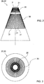
- the active phased array transmitting antenna 20 comprises a cylindrical or conical or truncated cone array of columns 21 of active transmission modules 22.
- the array of columns 21 of active transmission modules 22 is in particular, an array having the shape of a truncated cone with a circular base in which the columns 21 of active transmission modules 22 are directed along the generatrix of the aforesaid truncated cone.
- the aforementioned array of columns 21 of transmission modules 22 comprises one hundred columns 21 of active transmission modules 22 and each column 21 comprises sixteen active transmission modules, so that the number of active transmission modules 22 of the transmitting antenna is for example equal to one hundred and sixty.
- each of the columns 21 is a block physically independent of the others and is attached inside a support structure 27 of the transmitting antenna 20, for example of a tubular truncated-cone shape and for example made of carbon fibre or aluminium.
- a support structure 27 of the transmitting antenna 20 for example of a tubular truncated-cone shape and for example made of carbon fibre or aluminium.
- Such support structure 27 has slots for example, (intended as through-openings in the form of slots) at each of which a respective column 21 of active transmission modules 22 is attached.
- the aforesaid support structure 27 is covered with a radome, not shown in the figures, superposed and in contact with the support structure 27 and which is possibly made of a material suitable to act as a bandpass filter for the portion of spectrum of frequencies of interest.
- the radome is made of kevlar or glass fibre.
- each active transmission module 22 of the transmitting antenna 20 comprises in cascade: an input adapted to receive a modulated radio frequency signal RF_t to be transmitted, a phase-shifter 24 adapted to phase delay said modulated signal RF_t, a power amplifier 25 (for this reason the transmitting antenna is defined as an "active phased array") and a transmitting antenna element 23.
- the transmitting antenna element 23 is, for example, a patch antenna or a dipole antenna.
- the bistatic radar 1 comprises for example a signal generator 4 adapted to provide each active transmission module 22 with the radio frequency modulated signal to be transmitted RF_t.
- the bistatic radar 1 further comprises a radar activity block scheduler 2 adapted to control the signal generator 4 and the transmitting antenna 20.
- a radar activity block scheduler 2 adapted to control the signal generator 4 and the transmitting antenna 20.
- the phase shifter 24 is adapted to receive in input a digital control signal provided in output by the scheduler block 2 to control the phase delay introduced by the phase shifter 24 in the radio frequency modulated signal RF_t.
- the bistatic radar 1 further comprises a receiving antenna 30 comprising a truncated-cone array of columns 31 of reception modules 32 directed along the generatrix of a truncated cone.
- a receiving antenna 30 comprising a truncated-cone array of columns 31 of reception modules 32 directed along the generatrix of a truncated cone.
- the aforesaid truncated cone has a solid angle of aperture ⁇ of between 10° and 60°, extremes included.
- said solid angle of aperture ⁇ is equal to, or approximately equal to, 30°.
- Each reception module 32 comprises in cascade an antenna receiver element 33, an analog amplifier 34 and an analog to digital converter 36 adapted to produce digital samples in output.
- the analog amplifier 34 is an LNA (Low Noise Amplifier).
- Each antenna receiver element 33 is, for example, a patch antenna or a dipole.
- the analog to digital converter is for example an eight or sixteen bit converter.
- each receiver module 32 comprises upstream of the analog to digital converter 36, a low frequency conversion block 35, such as a mixer, adapted to convert the signal received into baseband or an intermediate frequency.
- each reception module 32 is adapted to receive in input a radiofrequency signal RF_o provided in output by the signal generator 4. It should be remembered that some of the components of the reception module 32 may be duplicated to allow the sampling of phase part and of the quadrature part of the signal received by the antenna element 33.
- each of the columns 31 or reception modules 32 is a block physically independent of the others and is attached inside a support structure 37 of the receiving antenna 30, for example of a tubular truncated-cone shape and for example made of carbon fibre or aluminium.
- a support structure 37 of the receiving antenna 30 has slots for example, (intended as through-openings in the form of slots) at each of which a respective column 31 of reception modules 32 is attached.
- the aforesaid support structure 37 is covered with a radome, not shown in the-figures, superposed and in contact with the support structure 37 and which is possibly made of a material suitable to act as a bandpass filter for the portion of spectrum of frequencies of interest.
- the radome is made of kevlar or glass fibre.
- both the support structures 27 and 37 are physically superposed (i.e. stacked one on top of the other) it is possible to provide for a single radome which covers both the transmitting antenna 20 and the receiving antenna 30.
- the transmitting antenna 20 and the receiving antenna 30 are two separate structures coaxially superposed.
- the transmitting antenna 20 and the receiving antenna 30 together form a continuous truncated-cone shape structure.
- the transmitting antenna 20 is superimposed to the receiving antenna 30.
- the number of reception modules 32 of the receiving antenna 30 is greater than the number of active transmission modules 22 of the transmitting antenna 20.
- the receiving antenna 30 comprises two hundred columns 31, each comprising sixty-four reception modules 32.
- the receiving antenna thus comprises twelve thousand, eight hundred reception modules 32 (while in the example described above, the transmitting antenna 20 comprises one thousand six hundred transmission modules 22, the number of reception modules 32 is therefore equal to eight times the number of transmission modules 22).
- the number of reception modules 32 in the same column 31 of the receiving antenna 30 is preferably greater than the number of transmission modules 22 in the same column 21 of the transmitting antenna 20.
- the receiving antenna 30 comprises for each of the columns 31 of reception modules 32 one or more FPGA boards adapted to process the signal received by the antenna receiver elements 33 to provide digital samples in output.
- FPGA boards For example, for each column 31 of sixty-four reception modules 32, sixteen FPGA boards are provided, each of which is operatively interconnected to four respective antenna receiver elements 33.
- a data concentrator column may also be provided for adapted to collect the digital samples supplied in output from all the reception modules 32 belonging to the same column 31 and to concentrate said samples in one or more signals.
- the bistatic radar 1 further comprises a full digital beam forming block 3 adapted to receive in input and numerically process the digital samples supplied in output by the receiving antenna 30.
- a full digital beam forming block 3 comprises a digital processor which receiving weight coefficients W in input is configured and adapted to calculate different weighted linear combinations of the aforesaid digital samples supplied in output by the receiving antenna 30.
- concentrator columns are provided for in the receiving antenna 30 it is possible to provide for an optic fibre connection between the concentrators columns and the full digital beam forming block 3.
- the bistatic radar 1 comprises a signal processor 5 operatively connected to the scheduler 2 and to the full digital beam forming block 3 and adapted to provide the latter the weight coefficients W and to receive in input from the latter the weighted linear combinations calculated.
- Each linear combination corresponds to a receiving antenna beam and the weight coefficients are preferably selected, as well as to determine the pointing of the receiving antenna beam, to create reception "holes" in directions which have a high level of environmental disturbance.
- the number of pulses and timing in transmission are scheduled by the scheduler block 2 as a function of radar activity in progress, which is automatically updated as a function of the processing of the signal processor 5.
- the bistatic radar 1 further comprises a data processor 6 operatively connected to the signal processor 5 and a command and control console 7 operatively connected to the data processor 6.
- the full digital beam forming block 3 is such as to process the digital samples numerically for the digital synthesis of a plurality of simultaneous and independent reception beams.
- the radar activity scheduler block 2 is adapted to control the transmitting antenna 20, the receiving antenna 30 and the full digital beam forming block 3 according to a first operating mode wherein the transmitting antenna 20 is controlled so that the radio frequency output signal 40 (i.e. irradiated signal) has N directional transmission beams 41, wherein N is an integer greater than or equal to one and in the case in which N is greater than one, said beams 41 are simultaneous, i.e. irradiated simultaneously.
- each directional transmission beam 41 are controllable in elevation and/or in azimuth by the radar activity scheduler block 2.
- each directional transmission beam 41 for example pencil-shaped, is produced by a respective sub array of adjacent columns 21 of active transmission modules 22 selectable electronically and centred in azimuth with respect to the pointing direction of the respective directional transmission beam 41.
- the aforesaid sub arrays of adjacent columns 21 do not have shared columns, i.e. they are not superposed.
- the transmitting antenna 20 is for example divided into four sub arrays of columns 21 and each of such sub arrays is dedicated to the issuance of a respective directional beam 41.
- the directional transmission beams 41 rotate in the azimuth plane making the sub arrays rotate electronically so as to ensure 360° monitoring.
- the scanning in azimuth takes place by means of a phase control of the transmission modules 22, in particular by means of the phase shifters 24.
- the receiving antenna 30 and the full digital beam forming block 3 are controlled by the radar activity scheduler 2 to produce for each of said N directional transmission beams 41 a respective plurality of M simultaneous receiving beams, where M is an integer greater than one and less than or equal to the number of columns 31 of reception modules 32. Consequently the full digital beam forming block 3 is configured to simultaneously synthesize MxN receiving beams.
- each plurality of M receiving beams is such as to point in the direction of a respective directional transmission beam 41 and is produced by one or more respective sub arrays of columns 31 of reception modules 32 selectable electronically and centred in azimuth with respect to the pointing direction of the respective directional transmission beam 41.
- the aforesaid sub arrays of columns 31 of reception modules 32 may also have shared columns 31, i.e. may be partially superposed.
- the bistatic radar 1 is configured to perform a surveillance and tracking activity and the scheduler block 2 is configured to control the transmitting antenna 20, the receiving antenna 30 and the full digital beam forming block 3 so as to electronically scan a sector to be monitored by means of said directional transmission 41 and reception beams, wherein the azimuth scanning is performed by means of the electronic selection of said sub arrays of columns 21, 31 (both of transmission modules and reception modules) while the scan in elevation is performed by means of a phase control.
- the radar activity scheduler block 2 is adapted to control the transmitting antenna 20, the receiving antenna 30 and the full- digital beam forming block 3 according to a second operating mode, selectable alternatively to the first.
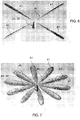
- the transmitting antenna 20 is controlled so that the radio frequency output signal 40 has a defocused radiation diagram 43 having a hemispherical or substantially hemispherical shape for example as shown in figure 8 .
- the radiation diagram has a shape with coverage in azimuth of 360° and in elevation of 70° and is definable in such regard as substantially hemispherical ( ⁇ beam).
- the receiving antenna 30 is controlled by simultaneously pointing one or more pluralities of M reception beams along one or more respective directions in which the presence of a target is signalled.
- the bistatic radar 1 it is thus possible to perform by means of the bistatic radar 1 a tracking activity of multiple targets simultaneously over short distances (for example up to distances of 10 km).
- the bistatic radar 1 be configured to perform:
- the transition between the first operating mode and the second operating mode and vice versa is gradual, for example progressively defocusing the directional beams 41 as shown in figure 7 until a transmitted signal is obtained which has a radiation pattern of the type shown in Figure 8 .
- the transmitted signal has a radiation pattern with a disc profile, with coverage in azimuth of 360°, amplitude of 5°-10° and variable pointing in elevation (2n beam).
- reception beams which point along all directions so as to entirely cover the transmitted signal are synthesized in reception by means of the digital beam forming block.
- this operating mode determines an increase in the refresh time of the radar data, and may thus be applied when this parameter is not relevant to the radar operations or when it is essential to minimize the transmission time to reduce the interception of the radar.
- the ship mast 50 is preferably installed on a mechanically stabilized platform.
- the ship mast has an ESM (Electronic Surveillance Measure) antenna at the top.
- the ship mast 50 comprises a transmitting antenna 20 and a receiving antenna 30 of the bistatic radar 1 described above, for example, operating at a frequency of 10 GHz.
- the ship mast 50 further comprises a further truncated-cone transmitting antenna 20a similar to the transmitting antenna 20 described above and which is for example an ECM (Electronic Countermeasure) antenna operating in the 2-18 GHz band.
- ECM Electronic Countermeasure
- the ship mast 50 further comprises a further truncated-cone transmitting antenna 20b similar to the transmitting antenna 20 described above and which for example is a dual antenna adapted to carry out both the function of transmitting antenna of a long-range radar (e.g. operating at a frequency of 1.3 GHz) and the function of a transmitting antenna of an IFF (Identification Friend or Foe) system, for example, operating at a frequency of 1.06 GHz.
- the ship mast 50 further comprises:
- a control room may be provided for housing the command and control console 7 of the block diagram in Figure 1 , and possibly other hardware/software equipment adapted to process the signals connected with the operation of the transmitting and receiving antennas described above.
- a bistatic radar 1 of the type described above can be installed on board a land vehicle 60, for example on top of a telescopic shaft 61.
- the aforementioned land vehicle 60 is a truck equipped with a habitable container housing the command and control console 7 of the block diagram of Figure 1 , and possibly other hardware/software equipment adapted to process the signals connected with the operation of the bistatic radar 1.
Landscapes
- Engineering & Computer Science (AREA)
- Radar, Positioning & Navigation (AREA)
- Remote Sensing (AREA)
- Physics & Mathematics (AREA)
- General Physics & Mathematics (AREA)
- Computer Networks & Wireless Communication (AREA)
- Computer Security & Cryptography (AREA)
- Variable-Direction Aerials And Aerial Arrays (AREA)
- Radar Systems Or Details Thereof (AREA)
Priority Applications (1)
| Application Number | Priority Date | Filing Date | Title |
|---|---|---|---|
| PL14838802T PL3092508T3 (pl) | 2014-01-09 | 2014-11-24 | Radar bistatyczny |
Applications Claiming Priority (2)
| Application Number | Priority Date | Filing Date | Title |
|---|---|---|---|
| ITRM20140005 | 2014-01-09 | ||
| PCT/IT2014/000310 WO2015104728A1 (en) | 2014-01-09 | 2014-11-24 | Bistatic radar |
Publications (2)
| Publication Number | Publication Date |
|---|---|
| EP3092508A1 EP3092508A1 (en) | 2016-11-16 |
| EP3092508B1 true EP3092508B1 (en) | 2018-01-31 |
Family
ID=50391293
Family Applications (1)
| Application Number | Title | Priority Date | Filing Date |
|---|---|---|---|
| EP14838802.8A Active EP3092508B1 (en) | 2014-01-09 | 2014-11-24 | Bistatic radar |
Country Status (11)
| Country | Link |
|---|---|
| US (1) | US20160327641A1 (no) |
| EP (1) | EP3092508B1 (no) |
| AU (1) | AU2014376819B2 (no) |
| BR (1) | BR112016014434B1 (no) |
| CA (1) | CA2932430C (no) |
| DK (1) | DK3092508T3 (no) |
| ES (1) | ES2667405T3 (no) |
| IL (1) | IL246360B (no) |
| PL (1) | PL3092508T3 (no) |
| RU (1) | RU2658671C2 (no) |
| WO (1) | WO2015104728A1 (no) |
Families Citing this family (14)
| Publication number | Priority date | Publication date | Assignee | Title |
|---|---|---|---|---|
| US10056699B2 (en) | 2015-06-16 | 2018-08-21 | The Mitre Cooperation | Substrate-loaded frequency-scaled ultra-wide spectrum element |
| US9991605B2 (en) | 2015-06-16 | 2018-06-05 | The Mitre Corporation | Frequency-scaled ultra-wide spectrum element |
| US10439851B2 (en) * | 2016-09-20 | 2019-10-08 | Ohio State Innovation Foundation | Frequency-independent receiver and beamforming technique |
| WO2018073676A1 (en) * | 2016-10-17 | 2018-04-26 | Fincantieri Spa | Radar system |
| US10854993B2 (en) | 2017-09-18 | 2020-12-01 | The Mitre Corporation | Low-profile, wideband electronically scanned array for geo-location, communications, and radar |
| KR102516365B1 (ko) * | 2018-05-25 | 2023-03-31 | 삼성전자주식회사 | 차량용 radar 제어 방법 및 장치 |
| US10886625B2 (en) | 2018-08-28 | 2021-01-05 | The Mitre Corporation | Low-profile wideband antenna array configured to utilize efficient manufacturing processes |
| RU2713103C1 (ru) * | 2018-09-28 | 2020-02-03 | Акционерное общество "Всероссийский научно-исследовательский институт радиотехники" | Способ формирования диаграммы направленности передающей активной антенной решетки и осесимметричная активная фазированная антенная решетка на его основе |
| RU2713219C1 (ru) * | 2019-07-04 | 2020-02-04 | Федеральное государственное автономное образовательное учреждение высшего образования "Санкт-Петербургский государственный электротехнический университет "ЛЭТИ" им. В.И. Ульянова (Ленина) | Мобильная когерентная радиолокационная система |
| RU2749652C2 (ru) * | 2019-11-25 | 2021-06-16 | Общество с ограниченной ответственностью "ГОУДИДЖИТАЛ" | Антенна комнатная телевизионная |
| CN111755825B (zh) * | 2020-06-23 | 2021-10-26 | 电子科技大学 | 一种基于堆叠贴片式匹配层的宽带宽角扫描相控阵天线 |
| CN112505434B (zh) * | 2020-11-24 | 2022-08-12 | 中国电子科技集团公司第三十八研究所 | 一种无源阵列天线波束扫描特性的测试方法 |
| AU2022226969A1 (en) | 2021-02-24 | 2023-09-14 | Bluehalo Llc | System and method for a digitally beamformed phased array feed |
| CN112910521B (zh) * | 2021-02-27 | 2022-04-05 | 中电万维信息技术有限责任公司 | 一种基于深度学习的mimo混合波束赋形方法 |
Family Cites Families (13)
| Publication number | Priority date | Publication date | Assignee | Title |
|---|---|---|---|---|
| US3697994A (en) * | 1971-07-19 | 1972-10-10 | Us Navy | Automatic beam steering technique for cylindrical-array radar antennas |
| US6388603B1 (en) * | 1980-12-11 | 2002-05-14 | Raytheon Company | System and method for bistatically determining altitude and slant range to a selected target |
| JPH06249945A (ja) * | 1993-02-25 | 1994-09-09 | Mitsubishi Electric Corp | レーダ装置 |
| JP3216713B2 (ja) * | 1998-12-08 | 2001-10-09 | 日本電気株式会社 | フェーズドアレイレーダ |
| RU2215303C2 (ru) * | 2001-09-28 | 2003-10-27 | Федеральное государственное унитарное предприятие "Научно-исследовательский институт измерительных приборов" | Способ контроля воздушного пространства |
| RU2285939C1 (ru) * | 2005-02-10 | 2006-10-20 | Открытое акционерное общество "Научно-исследовательский институт измерительных приборов" (ОАО "НИИИП") | Способ контроля воздушного пространства, облучаемого внешними источниками излучения, и радиолокационная станция для его реализации |
| DE102005029090A1 (de) * | 2005-06-23 | 2006-12-28 | Ewation Gmbh | Antennenanordnung |
| RU2293405C1 (ru) * | 2005-08-11 | 2007-02-10 | Федеральное государственное унитарное предприятие "Государственный московский завод "Салют" | Корабельная радиолокационная станция |
| RU2296343C1 (ru) * | 2005-10-19 | 2007-03-27 | Воронежское конструкторское бюро антенно-фидерных устройств (открытое акционерное общество) | Способ обнаружения объекта |
| EP1814197B1 (en) * | 2006-01-24 | 2009-11-04 | Nokia Siemens Networks S.p.A. | An antenna arrangement having unevenly separated elements |
| RU2324197C2 (ru) * | 2006-02-20 | 2008-05-10 | Федеральное Государственное Унитарное Предприятие "Нижегородский Научно-Исследовательский Институт Радиотехники" | Радиолокационный комплекс |
| US8284109B2 (en) * | 2007-10-31 | 2012-10-09 | Lockheed Martin Corporation | Telescoping radar array |
| US8344943B2 (en) * | 2008-07-28 | 2013-01-01 | Physical Domains, LLC | Low-profile omnidirectional retrodirective antennas |
-
2014
- 2014-11-24 DK DK14838802.8T patent/DK3092508T3/en active
- 2014-11-24 CA CA2932430A patent/CA2932430C/en active Active
- 2014-11-24 RU RU2016122083A patent/RU2658671C2/ru active
- 2014-11-24 AU AU2014376819A patent/AU2014376819B2/en active Active
- 2014-11-24 PL PL14838802T patent/PL3092508T3/pl unknown
- 2014-11-24 US US15/110,462 patent/US20160327641A1/en not_active Abandoned
- 2014-11-24 WO PCT/IT2014/000310 patent/WO2015104728A1/en active Application Filing
- 2014-11-24 BR BR112016014434-1A patent/BR112016014434B1/pt active IP Right Grant
- 2014-11-24 ES ES14838802.8T patent/ES2667405T3/es active Active
- 2014-11-24 EP EP14838802.8A patent/EP3092508B1/en active Active
-
2016
- 2016-06-20 IL IL246360A patent/IL246360B/en active IP Right Grant
Also Published As
| Publication number | Publication date |
|---|---|
| RU2016122083A (ru) | 2018-02-14 |
| CA2932430A1 (en) | 2015-07-16 |
| CA2932430C (en) | 2021-12-28 |
| US20160327641A1 (en) | 2016-11-10 |
| WO2015104728A1 (en) | 2015-07-16 |
| IL246360B (en) | 2020-03-31 |
| EP3092508A1 (en) | 2016-11-16 |
| IL246360A0 (en) | 2016-08-31 |
| PL3092508T3 (pl) | 2018-08-31 |
| AU2014376819A1 (en) | 2016-06-16 |
| BR112016014434A2 (no) | 2017-08-08 |
| ES2667405T3 (es) | 2018-05-10 |
| DK3092508T3 (en) | 2018-05-07 |
| AU2014376819B2 (en) | 2018-04-19 |
| BR112016014434B1 (pt) | 2022-09-13 |
| RU2658671C2 (ru) | 2018-06-22 |
Similar Documents
| Publication | Publication Date | Title |
|---|---|---|
| EP3092508B1 (en) | Bistatic radar | |
| RU2740218C2 (ru) | Радиолокационная система | |
| US10281571B2 (en) | Phased array antenna using stacked beams in elevation and azimuth | |
| US7737879B2 (en) | Split aperture array for increased short range target coverage | |
| US8456349B1 (en) | Three dimensional radar method and apparatus | |
| CN106980109B (zh) | 一种多子阵低空雷达 | |
| KR20150126997A (ko) | 다른 응용을 가진 원통형 어레이 안테나에 기초한 해상 레이더 | |
| CN116359897A (zh) | 一种全空域凝视数字阵列雷达系统 | |
| Fenner et al. | Test results of a space-time adaptive processing system for airborne early warning radar | |
| Yang et al. | Practical investigation of a MIMO radar system for small drones detection | |
| CN110879017B (zh) | 一种基于dbf的弹载探测装置 | |
| Huizing et al. | Compact scalable multifunction RF payload for UAVs with FMCW radar and ESM functionality | |
| CN104995796B (zh) | 接收器‑发送器 | |
| WO1986000760A1 (en) | Multibeam antenna, which can provide different beam positions according to the angular sector of interest | |
| Cattenoz et al. | An experimental demonstration of a posteriori digital calibration of MIMO radar system | |
| Kellett et al. | Multifunction Maritime Radar and RF Systems—Technology Challenges and Areas of Development | |
| Leonov | History of monopulse radar in the USSR | |
| Galati et al. | Time for a change in phased array radar architectures-Part I: Planar vs. conformal arrays | |
| Tan | Signal Processing Techniques for LFMCW Radar under Urban Low, Slow, and Small Conditions | |
| Dedden | SMART-L multibeam radar | |
| Sankowski et al. | Multifunction C-band radar development in Poland: Electronically scanned array technology | |
| Pell | A review of system performance requirements for phased array antennas | |
| Pietrasinski et al. | Selected tendencies of modern radars and radar systems development |
Legal Events
| Date | Code | Title | Description |
|---|---|---|---|
| PUAI | Public reference made under article 153(3) epc to a published international application that has entered the european phase |
Free format text: ORIGINAL CODE: 0009012 |
|
| 17P | Request for examination filed |
Effective date: 20160531 |
|
| AK | Designated contracting states |
Kind code of ref document: A1 Designated state(s): AL AT BE BG CH CY CZ DE DK EE ES FI FR GB GR HR HU IE IS IT LI LT LU LV MC MK MT NL NO PL PT RO RS SE SI SK SM TR |
|
| AX | Request for extension of the european patent |
Extension state: BA ME |
|
| DAX | Request for extension of the european patent (deleted) | ||
| GRAP | Despatch of communication of intention to grant a patent |
Free format text: ORIGINAL CODE: EPIDOSNIGR1 |
|
| INTG | Intention to grant announced |
Effective date: 20170920 |
|
| GRAS | Grant fee paid |
Free format text: ORIGINAL CODE: EPIDOSNIGR3 |
|
| GRAA | (expected) grant |
Free format text: ORIGINAL CODE: 0009210 |
|
| AK | Designated contracting states |
Kind code of ref document: B1 Designated state(s): AL AT BE BG CH CY CZ DE DK EE ES FI FR GB GR HR HU IE IS IT LI LT LU LV MC MK MT NL NO PL PT RO RS SE SI SK SM TR |
|
| REG | Reference to a national code |
Ref country code: GB Ref legal event code: FG4D Ref country code: CH Ref legal event code: EP |
|
| REG | Reference to a national code |
Ref country code: AT Ref legal event code: REF Ref document number: 967883 Country of ref document: AT Kind code of ref document: T Effective date: 20180215 |
|
| REG | Reference to a national code |
Ref country code: IE Ref legal event code: FG4D |
|
| REG | Reference to a national code |
Ref country code: DE Ref legal event code: R096 Ref document number: 602014020641 Country of ref document: DE |
|
| REG | Reference to a national code |
Ref country code: NL Ref legal event code: FP |
|
| REG | Reference to a national code |
Ref country code: SE Ref legal event code: TRGR |
|
| REG | Reference to a national code |
Ref country code: DK Ref legal event code: T3 Effective date: 20180503 |
|
| REG | Reference to a national code |
Ref country code: ES Ref legal event code: FG2A Ref document number: 2667405 Country of ref document: ES Kind code of ref document: T3 Effective date: 20180510 |
|
| REG | Reference to a national code |
Ref country code: LT Ref legal event code: MG4D |
|
| REG | Reference to a national code |
Ref country code: AT Ref legal event code: MK05 Ref document number: 967883 Country of ref document: AT Kind code of ref document: T Effective date: 20180131 |
|
| PG25 | Lapsed in a contracting state [announced via postgrant information from national office to epo] |
Ref country code: LT Free format text: LAPSE BECAUSE OF FAILURE TO SUBMIT A TRANSLATION OF THE DESCRIPTION OR TO PAY THE FEE WITHIN THE PRESCRIBED TIME-LIMIT Effective date: 20180131 Ref country code: NO Free format text: LAPSE BECAUSE OF FAILURE TO SUBMIT A TRANSLATION OF THE DESCRIPTION OR TO PAY THE FEE WITHIN THE PRESCRIBED TIME-LIMIT Effective date: 20180430 Ref country code: HR Free format text: LAPSE BECAUSE OF FAILURE TO SUBMIT A TRANSLATION OF THE DESCRIPTION OR TO PAY THE FEE WITHIN THE PRESCRIBED TIME-LIMIT Effective date: 20180131 Ref country code: FI Free format text: LAPSE BECAUSE OF FAILURE TO SUBMIT A TRANSLATION OF THE DESCRIPTION OR TO PAY THE FEE WITHIN THE PRESCRIBED TIME-LIMIT Effective date: 20180131 |
|
| PG25 | Lapsed in a contracting state [announced via postgrant information from national office to epo] |
Ref country code: IS Free format text: LAPSE BECAUSE OF FAILURE TO SUBMIT A TRANSLATION OF THE DESCRIPTION OR TO PAY THE FEE WITHIN THE PRESCRIBED TIME-LIMIT Effective date: 20180531 Ref country code: BG Free format text: LAPSE BECAUSE OF FAILURE TO SUBMIT A TRANSLATION OF THE DESCRIPTION OR TO PAY THE FEE WITHIN THE PRESCRIBED TIME-LIMIT Effective date: 20180430 Ref country code: LV Free format text: LAPSE BECAUSE OF FAILURE TO SUBMIT A TRANSLATION OF THE DESCRIPTION OR TO PAY THE FEE WITHIN THE PRESCRIBED TIME-LIMIT Effective date: 20180131 Ref country code: AT Free format text: LAPSE BECAUSE OF FAILURE TO SUBMIT A TRANSLATION OF THE DESCRIPTION OR TO PAY THE FEE WITHIN THE PRESCRIBED TIME-LIMIT Effective date: 20180131 Ref country code: GR Free format text: LAPSE BECAUSE OF FAILURE TO SUBMIT A TRANSLATION OF THE DESCRIPTION OR TO PAY THE FEE WITHIN THE PRESCRIBED TIME-LIMIT Effective date: 20180501 Ref country code: RS Free format text: LAPSE BECAUSE OF FAILURE TO SUBMIT A TRANSLATION OF THE DESCRIPTION OR TO PAY THE FEE WITHIN THE PRESCRIBED TIME-LIMIT Effective date: 20180131 |
|
| PG25 | Lapsed in a contracting state [announced via postgrant information from national office to epo] |
Ref country code: EE Free format text: LAPSE BECAUSE OF FAILURE TO SUBMIT A TRANSLATION OF THE DESCRIPTION OR TO PAY THE FEE WITHIN THE PRESCRIBED TIME-LIMIT Effective date: 20180131 Ref country code: AL Free format text: LAPSE BECAUSE OF FAILURE TO SUBMIT A TRANSLATION OF THE DESCRIPTION OR TO PAY THE FEE WITHIN THE PRESCRIBED TIME-LIMIT Effective date: 20180131 Ref country code: IT Free format text: LAPSE BECAUSE OF FAILURE TO SUBMIT A TRANSLATION OF THE DESCRIPTION OR TO PAY THE FEE WITHIN THE PRESCRIBED TIME-LIMIT Effective date: 20180131 Ref country code: RO Free format text: LAPSE BECAUSE OF FAILURE TO SUBMIT A TRANSLATION OF THE DESCRIPTION OR TO PAY THE FEE WITHIN THE PRESCRIBED TIME-LIMIT Effective date: 20180131 |
|
| REG | Reference to a national code |
Ref country code: DE Ref legal event code: R097 Ref document number: 602014020641 Country of ref document: DE |
|
| PG25 | Lapsed in a contracting state [announced via postgrant information from national office to epo] |
Ref country code: CZ Free format text: LAPSE BECAUSE OF FAILURE TO SUBMIT A TRANSLATION OF THE DESCRIPTION OR TO PAY THE FEE WITHIN THE PRESCRIBED TIME-LIMIT Effective date: 20180131 Ref country code: SM Free format text: LAPSE BECAUSE OF FAILURE TO SUBMIT A TRANSLATION OF THE DESCRIPTION OR TO PAY THE FEE WITHIN THE PRESCRIBED TIME-LIMIT Effective date: 20180131 Ref country code: SK Free format text: LAPSE BECAUSE OF FAILURE TO SUBMIT A TRANSLATION OF THE DESCRIPTION OR TO PAY THE FEE WITHIN THE PRESCRIBED TIME-LIMIT Effective date: 20180131 |
|
| PLBE | No opposition filed within time limit |
Free format text: ORIGINAL CODE: 0009261 |
|
| STAA | Information on the status of an ep patent application or granted ep patent |
Free format text: STATUS: NO OPPOSITION FILED WITHIN TIME LIMIT |
|
| 26N | No opposition filed |
Effective date: 20181102 |
|
| PG25 | Lapsed in a contracting state [announced via postgrant information from national office to epo] |
Ref country code: SI Free format text: LAPSE BECAUSE OF FAILURE TO SUBMIT A TRANSLATION OF THE DESCRIPTION OR TO PAY THE FEE WITHIN THE PRESCRIBED TIME-LIMIT Effective date: 20180131 |
|
| REG | Reference to a national code |
Ref country code: CH Ref legal event code: PL |
|
| PG25 | Lapsed in a contracting state [announced via postgrant information from national office to epo] |
Ref country code: LU Free format text: LAPSE BECAUSE OF NON-PAYMENT OF DUE FEES Effective date: 20181124 Ref country code: MC Free format text: LAPSE BECAUSE OF FAILURE TO SUBMIT A TRANSLATION OF THE DESCRIPTION OR TO PAY THE FEE WITHIN THE PRESCRIBED TIME-LIMIT Effective date: 20180131 |
|
| REG | Reference to a national code |
Ref country code: BE Ref legal event code: MM Effective date: 20181130 |
|
| REG | Reference to a national code |
Ref country code: IE Ref legal event code: MM4A |
|
| PG25 | Lapsed in a contracting state [announced via postgrant information from national office to epo] |
Ref country code: CH Free format text: LAPSE BECAUSE OF NON-PAYMENT OF DUE FEES Effective date: 20181130 Ref country code: LI Free format text: LAPSE BECAUSE OF NON-PAYMENT OF DUE FEES Effective date: 20181130 |
|
| PG25 | Lapsed in a contracting state [announced via postgrant information from national office to epo] |
Ref country code: IE Free format text: LAPSE BECAUSE OF NON-PAYMENT OF DUE FEES Effective date: 20181124 |
|
| PG25 | Lapsed in a contracting state [announced via postgrant information from national office to epo] |
Ref country code: BE Free format text: LAPSE BECAUSE OF NON-PAYMENT OF DUE FEES Effective date: 20181130 |
|
| PG25 | Lapsed in a contracting state [announced via postgrant information from national office to epo] |
Ref country code: MT Free format text: LAPSE BECAUSE OF NON-PAYMENT OF DUE FEES Effective date: 20181124 |
|
| PG25 | Lapsed in a contracting state [announced via postgrant information from national office to epo] |
Ref country code: TR Free format text: LAPSE BECAUSE OF FAILURE TO SUBMIT A TRANSLATION OF THE DESCRIPTION OR TO PAY THE FEE WITHIN THE PRESCRIBED TIME-LIMIT Effective date: 20180131 |
|
| PG25 | Lapsed in a contracting state [announced via postgrant information from national office to epo] |
Ref country code: PT Free format text: LAPSE BECAUSE OF FAILURE TO SUBMIT A TRANSLATION OF THE DESCRIPTION OR TO PAY THE FEE WITHIN THE PRESCRIBED TIME-LIMIT Effective date: 20180131 |
|
| PG25 | Lapsed in a contracting state [announced via postgrant information from national office to epo] |
Ref country code: HU Free format text: LAPSE BECAUSE OF FAILURE TO SUBMIT A TRANSLATION OF THE DESCRIPTION OR TO PAY THE FEE WITHIN THE PRESCRIBED TIME-LIMIT; INVALID AB INITIO Effective date: 20141124 Ref country code: CY Free format text: LAPSE BECAUSE OF FAILURE TO SUBMIT A TRANSLATION OF THE DESCRIPTION OR TO PAY THE FEE WITHIN THE PRESCRIBED TIME-LIMIT Effective date: 20180131 Ref country code: MK Free format text: LAPSE BECAUSE OF NON-PAYMENT OF DUE FEES Effective date: 20180131 |
|
| PGFP | Annual fee paid to national office [announced via postgrant information from national office to epo] |
Ref country code: NL Payment date: 20231124 Year of fee payment: 10 |
|
| PGFP | Annual fee paid to national office [announced via postgrant information from national office to epo] |
Ref country code: GB Payment date: 20231123 Year of fee payment: 10 |
|
| PGFP | Annual fee paid to national office [announced via postgrant information from national office to epo] |
Ref country code: ES Payment date: 20231201 Year of fee payment: 10 |
|
| PGFP | Annual fee paid to national office [announced via postgrant information from national office to epo] |
Ref country code: SE Payment date: 20231121 Year of fee payment: 10 Ref country code: DK Payment date: 20231124 Year of fee payment: 10 Ref country code: DE Payment date: 20231121 Year of fee payment: 10 |
|
| PGFP | Annual fee paid to national office [announced via postgrant information from national office to epo] |
Ref country code: PL Payment date: 20231030 Year of fee payment: 10 |
|
| PGFP | Annual fee paid to national office [announced via postgrant information from national office to epo] |
Ref country code: FR Payment date: 20240116 Year of fee payment: 10 |