EP3092385B1 - Organe de compensation pour au moins un compresseur et moteur à combustion interne - Google Patents
Organe de compensation pour au moins un compresseur et moteur à combustion interne Download PDFInfo
- Publication number
- EP3092385B1 EP3092385B1 EP14824399.1A EP14824399A EP3092385B1 EP 3092385 B1 EP3092385 B1 EP 3092385B1 EP 14824399 A EP14824399 A EP 14824399A EP 3092385 B1 EP3092385 B1 EP 3092385B1
- Authority
- EP
- European Patent Office
- Prior art keywords
- channel
- compressor
- main channel
- trim adjuster
- gas
- Prior art date
- Legal status (The legal status is an assumption and is not a legal conclusion. Google has not performed a legal analysis and makes no representation as to the accuracy of the status listed.)
- Active
Links
- 238000002485 combustion reaction Methods 0.000 title claims description 31
- 238000011144 upstream manufacturing Methods 0.000 claims description 17
- 239000000284 extract Substances 0.000 claims 1
- 230000008901 benefit Effects 0.000 description 4
- 230000003068 static effect Effects 0.000 description 4
- 230000009467 reduction Effects 0.000 description 3
- 238000009966 trimming Methods 0.000 description 3
- 230000007423 decrease Effects 0.000 description 2
- 230000000694 effects Effects 0.000 description 2
- 230000002349 favourable effect Effects 0.000 description 2
- 239000012530 fluid Substances 0.000 description 2
- 239000000203 mixture Substances 0.000 description 2
- 230000001105 regulatory effect Effects 0.000 description 2
- 230000004044 response Effects 0.000 description 2
- 230000005540 biological transmission Effects 0.000 description 1
- 230000015572 biosynthetic process Effects 0.000 description 1
- 230000001276 controlling effect Effects 0.000 description 1
- 230000003993 interaction Effects 0.000 description 1
- 230000007246 mechanism Effects 0.000 description 1
- 238000000034 method Methods 0.000 description 1
- 230000008569 process Effects 0.000 description 1
- 238000005086 pumping Methods 0.000 description 1
- 230000007480 spreading Effects 0.000 description 1
- 230000001052 transient effect Effects 0.000 description 1
- 230000007704 transition Effects 0.000 description 1
Images

Classifications
-
- F—MECHANICAL ENGINEERING; LIGHTING; HEATING; WEAPONS; BLASTING
- F02—COMBUSTION ENGINES; HOT-GAS OR COMBUSTION-PRODUCT ENGINE PLANTS
- F02B—INTERNAL-COMBUSTION PISTON ENGINES; COMBUSTION ENGINES IN GENERAL
- F02B37/00—Engines characterised by provision of pumps driven at least for part of the time by exhaust
- F02B37/12—Control of the pumps
- F02B37/22—Control of the pumps by varying cross-section of exhaust passages or air passages, e.g. by throttling turbine inlets or outlets or by varying effective number of guide conduits
- F02B37/225—Control of the pumps by varying cross-section of exhaust passages or air passages, e.g. by throttling turbine inlets or outlets or by varying effective number of guide conduits air passages
-
- F—MECHANICAL ENGINEERING; LIGHTING; HEATING; WEAPONS; BLASTING
- F02—COMBUSTION ENGINES; HOT-GAS OR COMBUSTION-PRODUCT ENGINE PLANTS
- F02M—SUPPLYING COMBUSTION ENGINES IN GENERAL WITH COMBUSTIBLE MIXTURES OR CONSTITUENTS THEREOF
- F02M26/00—Engine-pertinent apparatus for adding exhaust gases to combustion-air, main fuel or fuel-air mixture, e.g. by exhaust gas recirculation [EGR] systems
- F02M26/02—EGR systems specially adapted for supercharged engines
- F02M26/09—Constructional details, e.g. structural combinations of EGR systems and supercharger systems; Arrangement of the EGR and supercharger systems with respect to the engine
-
- F—MECHANICAL ENGINEERING; LIGHTING; HEATING; WEAPONS; BLASTING
- F04—POSITIVE - DISPLACEMENT MACHINES FOR LIQUIDS; PUMPS FOR LIQUIDS OR ELASTIC FLUIDS
- F04D—NON-POSITIVE-DISPLACEMENT PUMPS
- F04D29/00—Details, component parts, or accessories
- F04D29/40—Casings; Connections of working fluid
- F04D29/42—Casings; Connections of working fluid for radial or helico-centrifugal pumps
- F04D29/4206—Casings; Connections of working fluid for radial or helico-centrifugal pumps especially adapted for elastic fluid pumps
- F04D29/4213—Casings; Connections of working fluid for radial or helico-centrifugal pumps especially adapted for elastic fluid pumps suction ports
-
- F—MECHANICAL ENGINEERING; LIGHTING; HEATING; WEAPONS; BLASTING
- F04—POSITIVE - DISPLACEMENT MACHINES FOR LIQUIDS; PUMPS FOR LIQUIDS OR ELASTIC FLUIDS
- F04D—NON-POSITIVE-DISPLACEMENT PUMPS
- F04D29/00—Details, component parts, or accessories
- F04D29/40—Casings; Connections of working fluid
- F04D29/42—Casings; Connections of working fluid for radial or helico-centrifugal pumps
- F04D29/44—Fluid-guiding means, e.g. diffusers
- F04D29/441—Fluid-guiding means, e.g. diffusers especially adapted for elastic fluid pumps
-
- F—MECHANICAL ENGINEERING; LIGHTING; HEATING; WEAPONS; BLASTING
- F04—POSITIVE - DISPLACEMENT MACHINES FOR LIQUIDS; PUMPS FOR LIQUIDS OR ELASTIC FLUIDS
- F04D—NON-POSITIVE-DISPLACEMENT PUMPS
- F04D29/00—Details, component parts, or accessories
- F04D29/40—Casings; Connections of working fluid
- F04D29/42—Casings; Connections of working fluid for radial or helico-centrifugal pumps
- F04D29/44—Fluid-guiding means, e.g. diffusers
- F04D29/46—Fluid-guiding means, e.g. diffusers adjustable
- F04D29/462—Fluid-guiding means, e.g. diffusers adjustable especially adapted for elastic fluid pumps
-
- F—MECHANICAL ENGINEERING; LIGHTING; HEATING; WEAPONS; BLASTING
- F05—INDEXING SCHEMES RELATING TO ENGINES OR PUMPS IN VARIOUS SUBCLASSES OF CLASSES F01-F04
- F05D—INDEXING SCHEME FOR ASPECTS RELATING TO NON-POSITIVE-DISPLACEMENT MACHINES OR ENGINES, GAS-TURBINES OR JET-PROPULSION PLANTS
- F05D2250/00—Geometry
- F05D2250/50—Inlet or outlet
- F05D2250/51—Inlet
-
- Y—GENERAL TAGGING OF NEW TECHNOLOGICAL DEVELOPMENTS; GENERAL TAGGING OF CROSS-SECTIONAL TECHNOLOGIES SPANNING OVER SEVERAL SECTIONS OF THE IPC; TECHNICAL SUBJECTS COVERED BY FORMER USPC CROSS-REFERENCE ART COLLECTIONS [XRACs] AND DIGESTS
- Y02—TECHNOLOGIES OR APPLICATIONS FOR MITIGATION OR ADAPTATION AGAINST CLIMATE CHANGE
- Y02T—CLIMATE CHANGE MITIGATION TECHNOLOGIES RELATED TO TRANSPORTATION
- Y02T10/00—Road transport of goods or passengers
- Y02T10/10—Internal combustion engine [ICE] based vehicles
- Y02T10/12—Improving ICE efficiencies
Definitions
- the present invention relates to a trim plate for at least one compressor.
- the trim plate comprises at least one main channel and at least one bypass channel.
- the at least one main channel communicatively associated with at least one fresh gas line for fresh gas.
- the at least one bypass channel opens into the trim plate.
- At least one low-pressure exhaust gas recirculation is connected to the at least one bypass channel, so that exhaust gas can be fed to the at least one compressor.
- the present invention relates to an internal combustion engine.
- the internal combustion engine comprises at least one main channel, at least one exhaust gas line, at least one exhaust gas turbocharger and at least one low-pressure exhaust gas recirculation system.
- the at least one main channel communicatively associated with at least one fresh gas line for fresh gas.
- the at least one exhaust gas turbocharger has a turbine in the at least one exhaust gas line.
- the at least one low-pressure exhaust gas recirculation removes exhaust gas downstream of the turbine from the at least one exhaust gas line and is connected to at least one bypass channel such that exhaust gas can be fed to the at least one compressor.
- the at least one bypass channel opens into the trim plate.
- Trim plate of the type mentioned have been used for some time for compressors in internal combustion engines application.
- the fresh gas supplied via the at least one fresh gas train of an internal combustion engine is compressed.
- the flow conditions are changed at the compressor, so that the pumping limit of a compressor map is shifted in the direction of low mass flows at high pressure conditions.
- the at least one trim plate in the area of Pump limit cause an increase in the compressor efficiency, this changing an inflow cross section of fresh gas.
- the German patent application DE 10 2013 026 176 A1 discloses an internal combustion engine in which a trimmer comprises a cone, which in one embodiment consists of a plurality of blades.
- the lamellae are arranged in two layers, wherein the lamellae of each layer are spaced apart from each other and the two layers are offset relative to each other azimuthally to the axis of symmetry of the cone, so that the lamellae of one layer cover the distances between the lamellae of the respective other layer.
- LP-EGR low-pressure exhaust gas recirculation
- the exhaust gas withdrawn via the LP EGR downstream of a turbine of an exhaust gas turbocharger is introduced via a bypass channel upstream of the compressor of the exhaust gas turbocharger and drawn in by it with the fresh gas.
- LP-EGR low-pressure exhaust gas recirculation
- the German patent application with the file number DE 10 2013 003 418 A1 also discloses an internal combustion engine employing ND-EGR.
- the introduction of the recirculated exhaust gas advantageously takes place close to the compressor to one not to avoid or minimize the formation of condensate in the fresh gas.
- This arrangement also has the advantage that space is saved.
- the trim plate here is a funnel-shaped wall system, wherein an outlet cross-section of the wall system is variable by a more or less successful spreading of the wall system, so that a passage cross-section for the exhaust gas between the wall system and the housing is formed.
- the US 2007/266705 A1 describes a compressor whose housing inlet side forms a central main channel and two surrounding additional channels, of which an internal additional channel merges both at the proximal and distal with respect to a compressor impeller of the compressor end in the main channel, whereby this functionally can serve as a so-called map-stabilizing measure .
- the external additional channel can be used to supply an additional gas flow, which can also be recirculated exhaust gas, into the compressor, wherein the end of this external additional channel, which is proximal to the compressor impeller, merges into the inner additional channel.
- a flap valve is arranged, closed by the either only the inner additional channel or only the outer additional channel or both additional channels can be released.
- the WO 2007/130947 A1 discloses a tubular tube-shaped slide valve for controlling the quantity of an introduction of recirculated exhaust gas in a fresh gas line of an internal combustion engine.
- An object of the present invention is therefore to provide a trim plate for at least one compressor in which the feedability of recirculated exhaust gas is improved.
- trim plate for at least one compressor comprising the features in claim 1.
- the trimming plate according to the invention for at least one compressor comprises at least one main channel and at least one bypass channel.
- the at least one main channel communicatively associated with at least one fresh gas line for fresh gas.
- the at least one bypass channel opens into the trim plate.
- At least one low-pressure exhaust gas recirculation is connected to the at least one bypass channel, so that exhaust gas can be supplied to the at least one compressor.
- a communicative assignment is understood as meaning a fluidic connection or fluid-conducting connection.
- the fluidic connection may also be referred to as a communicating connection.
- at least one fresh gas line for fresh gas is fluidly connected to the at least one main channel.
- At least one sliding element is arranged in the trim plate.
- the sliding element is at least one radially outside of the sliding element leading secondary channel formed in the trim plate.
- the main channel leads radially inward through the sliding element and is enclosed by this.
- the indication radially inward or radially outward always refers to the flow direction of the fluid in the main channel as an axis.
- the secondary channel is closable at its upstream end by the sliding element by the sliding element is moved against the inner wall of the trim plate.
- the closed secondary channel only the flow path through the main channel is available to the fresh gas entering through the fresh gas channel.
- With a sealed secondary channel is not indicated that in this state, the secondary channel forms a closed space.
- the sub-channel continues to communicate with the main channel.
- a sealed subchannel merely indicates that the channel at its upstream end is substantially gas-tightly separated from the fresh gas channel.
- the at least one bypass channel opens into the secondary channel downstream of the closable, upstream end of the secondary channel.
- the bypass channel opens at a small distance to this end in the secondary channel, in any case before the downstream end of the secondary channel, where the secondary channel communicates with the main channel again.
- EGR valve a valve
- an amount of exhaust gas, which is recycled via the bypass channel in the secondary channel is adjustable.
- the trim plate according to the invention advantageously makes it possible to first influence the throughput of fresh gas through the trim plate. If the upstream end of the secondary channel is fully open, the maximum cross section is available for the fresh gas, since this can flow through both the main channel and the secondary channel. This position is accordingly set for maximum, preferably low-loss fresh gas flow. If the upstream end of the secondary channel is closed, the fresh gas is only the main channel and thus a smaller cross section to Available. It is intended to allow any number of intermediate positions between these two positions.
- the fresh gas of the main channel and the fresh gas and / or exhaust gas of the secondary channel is brought together upstream of the compressor and at a small distance to the compressor.
- the downstream end of the main channel is only slightly spaced from the inlet of the compressor.
- the distance of the downstream end of the main passage from the inlet of the compressor is less than the diameter of the main passage.
- a cross section of the at least one fresh gas line is greater than a cross section of the at least one main channel. Consequently, the trim plate with closed side channel thus viewed in the flow direction narrowing cross-section.
- a flow velocity of the fresh gas in the at least one main channel in the flow direction is greater.
- the EGR valve is open, turbulences are created in the downstream end of the main channel between the rapidly flowing fresh gas and the exhaust gas flowing in via the bypass channel and secondary channel, so that the two media are mixed as a result. In this process, thus, the kinetic energy is transferred from the fresh gas to the exhaust gas, whereby an effective delivery mechanism is available.
- exhaust backpressure which with the pressure in front of the compressor results in the pressure gradient relevant for the exhaust gas recirculation, may be lower.
- An exhaust flap which is usually at least partially closed in order to increase the exhaust gas backpressure, can in particular be closed less or fully opened, whereby the efficiency of the internal combustion engine is improved.
- the at least one sliding element is designed to be movable in a guide body which is fixedly arranged in the trim plate.
- the stationary guide body allows the distance of the downstream end of the main passage to the entrance of the compressor to be made constantly small.
- the movable design of the at least one sliding element can be configured concretely by means of different actuations.
- the at least one sliding element can be electrically, hydraulically, mechanically, pneumatically or magnetically controlled in its movement, wherein also further control can be realized.
- the trim actuator comprises two bypass channels.
- the bypass channels can then be arranged on both sides of the trim plate.
- the largest possible circumferential surface can be achieved, in which the bypass channels communicate with the trim plate or the secondary channel.
- the common mouth area of the bypass channels extends over more than 40% of the circumference of the trim plate.
- Favorable flow conditions in the main channel can be achieved by making the cross section of the main channel constant over the course of the main channel.
- the main channel is formed of guide body and sliding element, it should be ensured that the guide body and the sliding element have the same inner diameter.
- the trim plate according to the invention can be further improved by openings are provided in the sliding element and / or the guide body, which communicatively connect the secondary channel with the main channel.
- the improved mode of operation is based on the principle of a jet pump, which due to the reduced pressure and the increased velocity of the fresh gas in the main channel, the recirculated exhaust gas is accelerated through the openings by means of pulse transmission and entrained. As a result, even better mixing of the exhaust gas and the fresh gas and the possibility of further reduction of the exhaust backpressure are achieved.
- Such a configuration of the openings that the respective outlets of the openings in the main channel to the respective inlets of the openings in the secondary channel have an offset in the flow direction of the flow in the main channel, represents a particularly good design solution.
- the openings therefore run from radially outside to inside proportionally in Flow direction, whereby the flow through the openings is already accelerated initially in the main channel flow direction.
- the internal combustion engine comprises at least one main channel, at least one exhaust gas line, at least one exhaust gas turbocharger and at least one low-pressure exhaust gas recirculation system.
- the at least one main channel communicatively associated with at least one fresh gas line for fresh gas.
- the at least one exhaust gas turbocharger has a turbine in the at least one exhaust gas line.
- the at least one low-pressure exhaust gas recirculation removes exhaust gas downstream of the turbine from the at least one exhaust gas line and is connected to at least one bypass channel such that exhaust gas can be fed to the at least one compressor.
- the at least one bypass channel opens into the trim plate.
- At least one compressor is assigned a trim plate according to the embodiments and embodiments described above, so that the advantages mentioned for the trim plate also result for the internal combustion engine.
- the internal combustion engine according to the invention may comprise a valve in the at least one low-pressure exhaust gas recirculation in a further embodiment.
- This valve then serves as a control or regulating valve for the low-pressure exhaust gas recirculation (EGR valve).
- the turbine of the internal combustion engine may in particular have a variable turbine geometry (VTG), whereby the characteristic map of the turbine similar to the characteristics of the compressor with the trim plate according to the invention is expandable and the interaction of the turbine and compressor is improved.
- VGT variable turbine geometry
- the internal combustion engine may be a spark-ignited or (preferably) a self-igniting internal combustion engine.
- FIG. 1 shows a schematic cross-sectional view of the trim plate 10 for a compressor 30 according to the invention in a preferred embodiment.
- the trim plate 10 here comprises a main channel 12 and two bypass channels 16. Since one of the two bypass channels 16 is not visible in this cross-sectional view, it is at this point FIG. 2 directed, there this is a perspective view of the trim plate 10 according to the invention Fig.1 represents, in which both bypass channels 16 are shown.
- the main channel 12 of the trimming actuator 10 is associated communicatively or with fluid connection a fresh gas line 14 for fresh gas.
- the two bypass channels 16 open into the trim plate 10 and there in the secondary channel 26.
- both bypass channels 16 are connected to a low-pressure exhaust gas recirculation 18 so that the compressor 30 exhaust gas via the trim plate 10 can be fed.
- the connection of the low-pressure exhaust gas recirculation 18 with the two bypass channels 16 is in Fig. 2 shown.
- a sliding element 20 is initially arranged along the flow direction R and a guide body 24 is arranged downstream of the sliding element 20.
- the guide body 24 is rigid, in other words immovable, arranged in the trim plate 10.
- the sliding member 20 is slidably received in the guide body 24 substantially along the flow direction R.
- the guide body 24 terminates shortly before the downstream end of the trim plate 10.
- the trim plate 10 is followed by the compressor 30 shown only schematically.
- Radially within the guide body 24 and sliding element 20 of the main channel 12 is formed.
- the secondary channel 26 has a seen in the flow direction R, annular cross-section.
- the bypass channels 16 open into the housing of the trim actuator 10 and communicate with the secondary channel 26th
- Fig. 1 shows a switching state of Trimmstellers 10, wherein the sliding member 20 is displaced maximum against the flow direction R.
- An outer surface of the sliding element 20 abuts the housing of the trim plate 10 and thus substantially hermetically seals the upstream end of the secondary channel 26.
- the fresh gas line 14 can therefore no longer communicate with the secondary channel 26.
- the flow is in this switching state, only the main channel 12 available.
- the diameter and thus also the cross-section d H of the main channel 12 is smaller than the cross section d F of the fresh gas train 14.
- the compressor 30 is flowed through by the reduced cross-section d H of the main channel 12 with reduced trim, whereby the surge limit of the compressor 30 is shifted in the compressor map in the direction of low mass flows at high pressure conditions. Furthermore, the flow velocity in the main channel 12 is increased and the static pressure is reduced, whereby a better mixing of the low-pressure exhaust gas recirculation 18, the bypass channels 16 and the secondary channel 26th recirculated exhaust gas with the flowing through the main channel 12 fresh gas before the compressor 30 is made possible. Finally, the reduced static pressure causes a better feedability of the exhaust gas, so that optionally the exhaust back pressure can be reduced.
- An unillustrated switching state is that the sliding element 20 is displaced maximally in the flow direction R and against the guide body 24.
- the secondary channel 26 is open both downstream and upstream, so that fresh gas from the fresh gas line 14 can flow into the secondary channel 26.
- the flow cross-section in the trim plate is increased, since the annular cross-section of the secondary channel 26 is added to the cross-section d H of the main channel 12.
- This switching position is selected for maximum, preferably low-loss throughput of fresh gas and / or exhaust gas.
- the compressor 30 is flown with a larger trim. Between the two described Endanschlag tooen any number of intermediate positions can be adjusted by moving the sliding element 20. In the embodiment according to Fig. 1 it is a preferred embodiment, since by means of the rigidly arranged guide body 24, the end of the main channel 12 has a constant distance from the compressor 30 even when the sliding element is displaced.
- FIG. 2 shows a perspective view of Trimmstellers invention 10 after Fig.1 , All elements are already in FIG. 1 described so that a renewed description of these is omitted.
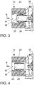
- FIGS. 3, 4 and 5 show a schematic course of the adjustment of a sliding element 20 in the trimming plate 10 according to the invention according to a second embodiment.
- This embodiment has no guide body 24.
- a single sliding element 20 is arranged in the trim plate 10.
- Fig. 4 shows a mean switching position of the sliding element 20.
- the secondary channel 26 is open upstream, whereby fresh gas from the fresh gas line 14 can flow into the secondary channel 26.
- the cross section of the main channel 12 and the cross section of the secondary channel 26 are available within the trim plate 10. This switching position is selected for maximum, preferably low-loss throughput at high trim. Exhaust gas can be fed into the secondary duct 26.
- Fig. 5 shows a switching position in which the sliding element 20 is displaced maximally against the flow direction R.
- the secondary channel 26 is closed at its upstream end, in that the sliding element 20 is in this case substantially airtight against the housing of the trim plate 10.
- This shift position is selected for maximum feedability of recirculated exhaust gas.
- the flow is in Trimmsteller 10 only the cross section of the main channel 12 is available, whereby the flow accelerates and the static pressure is reduced. As a result, there is a favorable pressure gradient of the exhaust counterpressure to the pressure in the trim plate 10 or in front of the compressor 30 for the recirculated exhaust gas which flows into the secondary duct 26.
- Fig. 3 shows a further switching position in which the sliding element 20 is displaced maximally in the flow direction R.
- the secondary channel 26 is closed at its downstream end, in that the sliding element 20 is in this case substantially airtight against the housing of the trim plate 10.
- This switch position is selected for minimum compressor trim.
- the flow is in Trimmsteller 10 only the cross section of the main channel 12 is available.
- the main channel 12 ends at a short distance in front of the compressor 30, so that the compressor 30 is flown with the small cross section of the main channel 12.
- the surge limit of the compressor 30 is shifted in the compressor map in the direction of low mass flows at high pressure conditions.
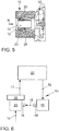
- FIG. 6 shows a schematic representation of the internal combustion engine 50 according to the invention with a trim plate 10 for the compressor 30 according to the Fig. 1 to 5 and 7 ,
- the internal combustion engine 50 comprises in this embodiment a main channel 12, an exhaust line 52, an exhaust gas turbocharger 54 and a low pressure exhaust gas recirculation 18.
- the main channel 12 communicatively associated with a fresh gas line 14 for fresh gas.
- the exhaust gas turbocharger 54 has a turbine 56 in the exhaust line 52.
- the low-pressure exhaust gas recirculation 18 removes exhaust gas downstream of the turbine 56 from the exhaust line 52 and is connected to the bypass channel 16, so that exhaust gas can be fed to the at least one compressor 30.
- the bypass channel 16 thus opens into the trim plate 10. According to the compressor 30 of the trim plate 10 from the FIGS. 1 to 5 and 7 upstream, so that thereby the advantages mentioned for the trim plate 10 also result for the internal combustion engine 50.
- Internal combustion engine 50 may provide a valve 58 in low pressure exhaust gas recirculation 18, as shown here.
- This valve 58 then serves as a control or regulating valve for the low-pressure exhaust gas recirculation 18 and is commonly referred to as EGR valve.
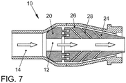
- Fig. 7 shows a third embodiment of the trim plate 10 according to the invention for a compressor 30.
- the third embodiment is substantially in accordance with the first embodiment according to the Fig. 1 match.
- the third embodiment in contrast to the second embodiment according to the FIGS. 3 to 5 a rigidly arranged in the trim plate 10 guide body 24 and a movable sliding element 20.
- Characteristic of the third embodiment are openings 28 which are introduced into the guide body 24.
- the sub-channel 26 communicates through the guide body 24 with the main channel 12.
- the openings 28 are inclined radially from the outside to the inside in the flow direction R.
Claims (10)
- Organe de compensation (10) pour au moins un compresseur (30), comprenant
au moins un conduit principal (12) auquel est associée de manière communicante au moins une ligne de gaz frais (14) pour du gaz frais,
au moins un conduit de dérivation (16), qui débouche dans l'organe de compensation (10),
et au moins une recirculation de gaz d'échappement à basse pression (18) étant connectée à l'au moins un conduit de dérivation (16), de telle sorte que du gaz d'échappement puisse être acheminé à l'au moins un compresseur (30),
caractérisé en ce
qu'au moins un élément coulissant (20) est disposé dans l'organe de compensation (10), lequel constitue au moins un conduit secondaire (26) conduisant radialement à l'extérieur autour de l'élément coulissant (20) et lequel entoure le conduit principal (12) conduisant radialement à l'intérieur à travers l'élément coulissant (20), le conduit secondaire (26) pouvant être fermé à son extrémité amont par l'élément coulissant (20) et le conduit de dérivation (16) débouchant en aval de cette extrémité dans le conduit secondaire (26) . - Organe de compensation (10) selon la revendication 1, caractérisé en ce que le gaz frais du conduit principal (12) et le gaz frais et/ou le gaz d'échappement du conduit secondaire (26) sont réunis en amont du compresseur (30) et à faible distance du compresseur (30).
- Organe de compensation (10) selon la revendication 1 ou 2, caractérisé en ce qu'une section transversale (dF) de l'au moins une ligne de gaz frais (14) est supérieure à une section transversale (dH) de l'au moins un conduit principal (12).
- Organe de compensation (10) selon l'une quelconque des revendications précédentes, caractérisé en ce que l'au moins un élément coulissant (20) est réalisé de manière déplaçable dans un corps de guidage (24) qui est disposé fixement dans l'organe de compensation (10).
- Organe de compensation (10) selon l'une quelconque des revendications précédentes, caractérisé en ce que deux conduits de dérivation (16) sont disposés de chaque côté de l'organe de compensation (10) et la surface d'embouchure commune des conduits de dérivation (16) s'étend sur plus de 40 % de la périphérie de l'organe de compensation (10).
- Organe de compensation (10) selon l'une quelconque des revendications 3 à 5, caractérisé en ce que la section transversale (dH) de l'au moins un conduit principal (12) est constante.
- Organe de compensation (10) selon l'une quelconque des revendications précédentes, caractérisé en ce que des ouvertures (28) sont prévues dans l'élément coulissant (20), lesquelles relient le conduit secondaire (26) de manière communicante avec le conduit principal (12).
- Organe de compensation (10) selon l'une quelconque des revendications 4 à 7, caractérisé en ce que des ouvertures (28) sont prévues dans le corps de guidage (20), lesquelles relient le conduit secondaire (26) de manière communicante avec le conduit principal (12).
- Organe de compensation (10) selon l'une quelconque des revendications 7 ou 8, caractérisé en ce que des sorties respectives des ouvertures (28) dans le conduit principal (12) vers des entrées respectives des ouvertures (28) dans le conduit secondaire (26) présentent un décalage dans le sens d'écoulement par rapport à l'écoulement dans le conduit principal (12).
- Moteur à combustion interne (50) comprenant au moins un conduit principal (12), auquel est associée de manière communicante au moins une ligne de gaz frais (14) pour du gaz frais, au moins une ligne de gaz d'échappement (52), au moins un turbocompresseur à gaz d'échappement (54) qui présente une turbine (56) dans l'au moins une ligne de gaz d'échappement (52), au moins une recirculation de gaz d'échappement à basse pression (18) qui prélève du gaz d'échappement en aval de la turbine (56) depuis l'au moins une ligne de gaz d'échappement (52) et qui est connectée à l'au moins un conduit de dérivation (16) de telle sorte, l'au moins un conduit de dérivation (16) débouchant dans l'organe de compensation (10), de telle sorte que le gaz d'échappement puisse être acheminé à l'au moins un compresseur (30), caractérisé en ce qu'un organe de compensation (10) selon l'une quelconque des revendications précédentes est associé à l'au moins un compresseur (30).
Applications Claiming Priority (2)
| Application Number | Priority Date | Filing Date | Title |
|---|---|---|---|
| DE102013226081 | 2013-12-16 | ||
| PCT/EP2014/077580 WO2015091268A1 (fr) | 2013-12-16 | 2014-12-12 | Organe de compensation pour au moins un compresseur et moteur à combustion interne |
Publications (2)
| Publication Number | Publication Date |
|---|---|
| EP3092385A1 EP3092385A1 (fr) | 2016-11-16 |
| EP3092385B1 true EP3092385B1 (fr) | 2018-02-28 |
Family
ID=52292872
Family Applications (1)
| Application Number | Title | Priority Date | Filing Date |
|---|---|---|---|
| EP14824399.1A Active EP3092385B1 (fr) | 2013-12-16 | 2014-12-12 | Organe de compensation pour au moins un compresseur et moteur à combustion interne |
Country Status (3)
| Country | Link |
|---|---|
| EP (1) | EP3092385B1 (fr) |
| DE (1) | DE102014225716A1 (fr) |
| WO (1) | WO2015091268A1 (fr) |
Families Citing this family (11)
| Publication number | Priority date | Publication date | Assignee | Title |
|---|---|---|---|---|
| US9777640B2 (en) * | 2014-11-04 | 2017-10-03 | Honeywell International Inc. | Adjustable-trim centrifugal compressor, and turbocharger having same |
| DE102017209598A1 (de) * | 2016-11-16 | 2018-05-17 | Volkswagen Aktiengesellschaft | Verdichter, Abgasturbolader und Brennkraftmaschine |
| DE102017219165B4 (de) * | 2017-10-25 | 2022-10-27 | Volkswagen Aktiengesellschaft | Verdichter, Abgasturbolader und Brennkraftmaschine |
| DE102018204469A1 (de) * | 2018-03-23 | 2019-09-26 | Volkswagen Aktiengesellschaft | Verdichter, Brennkraftmaschine und Kraftfahrzeug |
| DE102018206432A1 (de) * | 2018-04-25 | 2019-10-31 | Volkswagen Aktiengesellschaft | Verdichter, Abgasturbolader und Brennkraftmaschine |
| DE102018211095A1 (de) | 2018-07-05 | 2020-01-09 | Volkswagen Aktiengesellschaft | Verfahren zum Betreiben eines Kraftfahrzeugs und Kraftfahrzeug |
| DE102018211094A1 (de) | 2018-07-05 | 2020-01-09 | Volkswagen Aktiengesellschaft | Verfahren zum Betreiben einer Brennkraftmaschine, Brennkraftmaschine und Kraftfahrzeug |
| DE102018211091A1 (de) | 2018-07-05 | 2020-01-09 | Volkswagen Aktiengesellschaft | Verfahren zum Betreiben einer Brennkraftmaschine und Brennkraftmaschine |
| DE102018211540A1 (de) | 2018-07-11 | 2020-01-16 | Volkswagen Aktiengesellschaft | Verdichter mit einem Trimmsteller |
| WO2020031507A1 (fr) | 2018-08-07 | 2020-02-13 | 株式会社Ihi | Compresseur centrifuge et compresseur à suralimentation |
| WO2022214852A1 (fr) * | 2021-04-09 | 2022-10-13 | Mitsubishi Heavy Industries Engine & Turbocharger, Ltd. | Alimentation en mélange d'air et de gaz d'échappement d'une roue de compresseur d'un compresseur |
Family Cites Families (8)
| Publication number | Priority date | Publication date | Assignee | Title |
|---|---|---|---|---|
| US20070256413A1 (en) * | 2006-05-02 | 2007-11-08 | Honeywell International, Inc. | Variable geometry EGR mixer and system |
| US7698894B2 (en) * | 2006-05-22 | 2010-04-20 | International Engine Intellectual Property Company, Llc | Engine intake air compressor and method |
| CN102203429B (zh) * | 2008-11-18 | 2015-05-20 | 博格华纳公司 | 排气涡轮增压器的压缩机 |
| DE102008060944A1 (de) * | 2008-12-06 | 2010-06-10 | Daimler Ag | Heiß-Gas-Turboaufladung |
| DE102009000799A1 (de) | 2009-02-12 | 2010-08-19 | Ford Global Technologies, LLC, Dearborn | Mittels Verdichter aufgeladene Brennkraftmaschine und Verfahren zum Betreiben einer derartigen Brennkraftmaschine |
| JP5047352B2 (ja) * | 2010-12-28 | 2012-10-10 | 三菱重工業株式会社 | 排気ターボ過給機のハウジング構造 |
| US9777737B2 (en) * | 2011-11-14 | 2017-10-03 | Honeywell International Inc. | Adjustable compressor trim |
| DE102013003418A1 (de) * | 2013-02-28 | 2014-08-28 | Volkswagen Aktiengesellschaft | Brennkraftmaschine |
-
2014
- 2014-12-12 WO PCT/EP2014/077580 patent/WO2015091268A1/fr active Application Filing
- 2014-12-12 EP EP14824399.1A patent/EP3092385B1/fr active Active
- 2014-12-12 DE DE102014225716.6A patent/DE102014225716A1/de not_active Withdrawn
Also Published As
| Publication number | Publication date |
|---|---|
| EP3092385A1 (fr) | 2016-11-16 |
| WO2015091268A1 (fr) | 2015-06-25 |
| DE102014225716A1 (de) | 2015-07-09 |
Similar Documents
| Publication | Publication Date | Title |
|---|---|---|
| EP3092385B1 (fr) | Organe de compensation pour au moins un compresseur et moteur à combustion interne | |
| DE112015005540B4 (de) | Abgasturbolader mit kombinierter Einstelleinrichtung für Bypassventil und Flutenverbindung | |
| EP2025896B1 (fr) | Compresseur radial pour turbocompresseur | |
| EP2981699B1 (fr) | Moteur | |
| EP3051099B1 (fr) | Compresseur à géometrie d'écoulement variable | |
| DE60311908T2 (de) | Turbine mit verschiebbaren Leitschaufeln | |
| DE10152804A1 (de) | Brennkraftmaschine mit einem Abgasturbolader und einer Abgasrückführungsvorrichtung | |
| DE102011010744A1 (de) | Turbine für einen Abgasturbolader sowie Abgasturbolader mit einer solchen Turbine | |
| DE10029808C1 (de) | Abgasturbolader für eine Brennkraftmaschine | |
| DE102015209704A1 (de) | Verdichter mit variabler Anströmgeometrie | |
| DE102009034653A1 (de) | Brennkraftmaschine und Frischluftanlage | |
| WO2018091269A1 (fr) | Compresseur, turbocompresseur à gaz d'échappement et moteur à combustion interne | |
| DE102014221049A1 (de) | Anordnung und Verfahren zum Abblasen von Verdichterluft in einem Triebwerk | |
| DE10132672A1 (de) | Abgasturbolader für eine Brennkraftmaschine | |
| DE112015003873B4 (de) | Motorauslasssystem und einstellbares, verlustarmes ventil zur bereitstellung einer hochdruckschleifen-abgasrückführung | |
| WO2011120825A1 (fr) | Carter de turbocompresseur doté d'un dispositif à soupape et procédé de production d'un tel carter de turbocompresseur | |
| EP2959152B1 (fr) | Conduit de gaz d'échappement pour moteur à combustion interne | |
| DE102011120880A1 (de) | Turbine für einen Abgasturbolader | |
| DE10329281A1 (de) | Verdichter im Ansaugtrakt einer Brennkraftmaschine | |
| EP2024618B1 (fr) | Turbocompresseur pour un moteur à combustion interne | |
| DE102011120555A1 (de) | Leitgitter für eine Turbine eines Abgasturboladers sowie Turbine für einen Abgasturbolader | |
| DE102010047252A1 (de) | Leitapparat | |
| DE102015012726A1 (de) | Turbine für einen Abgasturbolader | |
| DE102015011906A1 (de) | Verdichter, insbesondere Radialverdichter, für einen Abgasturbolader | |
| DE102012022510A1 (de) | Turbine für einen Abgasturbolader sowie Verfahren zum Betreiben einer solchen Turbine |
Legal Events
| Date | Code | Title | Description |
|---|---|---|---|
| PUAI | Public reference made under article 153(3) epc to a published international application that has entered the european phase |
Free format text: ORIGINAL CODE: 0009012 |
|
| 17P | Request for examination filed |
Effective date: 20160718 |
|
| AK | Designated contracting states |
Kind code of ref document: A1 Designated state(s): AL AT BE BG CH CY CZ DE DK EE ES FI FR GB GR HR HU IE IS IT LI LT LU LV MC MK MT NL NO PL PT RO RS SE SI SK SM TR |
|
| AX | Request for extension of the european patent |
Extension state: BA ME |
|
| DAX | Request for extension of the european patent (deleted) | ||
| GRAP | Despatch of communication of intention to grant a patent |
Free format text: ORIGINAL CODE: EPIDOSNIGR1 |
|
| INTG | Intention to grant announced |
Effective date: 20170925 |
|
| GRAS | Grant fee paid |
Free format text: ORIGINAL CODE: EPIDOSNIGR3 |
|
| GRAA | (expected) grant |
Free format text: ORIGINAL CODE: 0009210 |
|
| AK | Designated contracting states |
Kind code of ref document: B1 Designated state(s): AL AT BE BG CH CY CZ DE DK EE ES FI FR GB GR HR HU IE IS IT LI LT LU LV MC MK MT NL NO PL PT RO RS SE SI SK SM TR |
|
| REG | Reference to a national code |
Ref country code: GB Ref legal event code: FG4D Free format text: NOT ENGLISH Ref country code: CH Ref legal event code: EP |
|
| REG | Reference to a national code |
Ref country code: AT Ref legal event code: REF Ref document number: 974402 Country of ref document: AT Kind code of ref document: T Effective date: 20180315 |
|
| REG | Reference to a national code |
Ref country code: IE Ref legal event code: FG4D Free format text: LANGUAGE OF EP DOCUMENT: GERMAN |
|
| REG | Reference to a national code |
Ref country code: DE Ref legal event code: R096 Ref document number: 502014007483 Country of ref document: DE |
|
| REG | Reference to a national code |
Ref country code: NL Ref legal event code: MP Effective date: 20180228 |
|
| REG | Reference to a national code |
Ref country code: LT Ref legal event code: MG4D |
|
| PG25 | Lapsed in a contracting state [announced via postgrant information from national office to epo] |
Ref country code: FI Free format text: LAPSE BECAUSE OF FAILURE TO SUBMIT A TRANSLATION OF THE DESCRIPTION OR TO PAY THE FEE WITHIN THE PRESCRIBED TIME-LIMIT Effective date: 20180228 Ref country code: NO Free format text: LAPSE BECAUSE OF FAILURE TO SUBMIT A TRANSLATION OF THE DESCRIPTION OR TO PAY THE FEE WITHIN THE PRESCRIBED TIME-LIMIT Effective date: 20180528 Ref country code: HR Free format text: LAPSE BECAUSE OF FAILURE TO SUBMIT A TRANSLATION OF THE DESCRIPTION OR TO PAY THE FEE WITHIN THE PRESCRIBED TIME-LIMIT Effective date: 20180228 Ref country code: ES Free format text: LAPSE BECAUSE OF FAILURE TO SUBMIT A TRANSLATION OF THE DESCRIPTION OR TO PAY THE FEE WITHIN THE PRESCRIBED TIME-LIMIT Effective date: 20180228 Ref country code: LT Free format text: LAPSE BECAUSE OF FAILURE TO SUBMIT A TRANSLATION OF THE DESCRIPTION OR TO PAY THE FEE WITHIN THE PRESCRIBED TIME-LIMIT Effective date: 20180228 Ref country code: NL Free format text: LAPSE BECAUSE OF FAILURE TO SUBMIT A TRANSLATION OF THE DESCRIPTION OR TO PAY THE FEE WITHIN THE PRESCRIBED TIME-LIMIT Effective date: 20180228 Ref country code: CY Free format text: LAPSE BECAUSE OF FAILURE TO SUBMIT A TRANSLATION OF THE DESCRIPTION OR TO PAY THE FEE WITHIN THE PRESCRIBED TIME-LIMIT Effective date: 20180228 |
|
| PG25 | Lapsed in a contracting state [announced via postgrant information from national office to epo] |
Ref country code: BG Free format text: LAPSE BECAUSE OF FAILURE TO SUBMIT A TRANSLATION OF THE DESCRIPTION OR TO PAY THE FEE WITHIN THE PRESCRIBED TIME-LIMIT Effective date: 20180528 Ref country code: GR Free format text: LAPSE BECAUSE OF FAILURE TO SUBMIT A TRANSLATION OF THE DESCRIPTION OR TO PAY THE FEE WITHIN THE PRESCRIBED TIME-LIMIT Effective date: 20180529 Ref country code: SE Free format text: LAPSE BECAUSE OF FAILURE TO SUBMIT A TRANSLATION OF THE DESCRIPTION OR TO PAY THE FEE WITHIN THE PRESCRIBED TIME-LIMIT Effective date: 20180228 Ref country code: LV Free format text: LAPSE BECAUSE OF FAILURE TO SUBMIT A TRANSLATION OF THE DESCRIPTION OR TO PAY THE FEE WITHIN THE PRESCRIBED TIME-LIMIT Effective date: 20180228 Ref country code: RS Free format text: LAPSE BECAUSE OF FAILURE TO SUBMIT A TRANSLATION OF THE DESCRIPTION OR TO PAY THE FEE WITHIN THE PRESCRIBED TIME-LIMIT Effective date: 20180228 |
|
| PG25 | Lapsed in a contracting state [announced via postgrant information from national office to epo] |
Ref country code: MT Free format text: LAPSE BECAUSE OF FAILURE TO SUBMIT A TRANSLATION OF THE DESCRIPTION OR TO PAY THE FEE WITHIN THE PRESCRIBED TIME-LIMIT Effective date: 20180228 |
|
| PG25 | Lapsed in a contracting state [announced via postgrant information from national office to epo] |
Ref country code: PL Free format text: LAPSE BECAUSE OF FAILURE TO SUBMIT A TRANSLATION OF THE DESCRIPTION OR TO PAY THE FEE WITHIN THE PRESCRIBED TIME-LIMIT Effective date: 20180228 Ref country code: EE Free format text: LAPSE BECAUSE OF FAILURE TO SUBMIT A TRANSLATION OF THE DESCRIPTION OR TO PAY THE FEE WITHIN THE PRESCRIBED TIME-LIMIT Effective date: 20180228 Ref country code: AL Free format text: LAPSE BECAUSE OF FAILURE TO SUBMIT A TRANSLATION OF THE DESCRIPTION OR TO PAY THE FEE WITHIN THE PRESCRIBED TIME-LIMIT Effective date: 20180228 Ref country code: IT Free format text: LAPSE BECAUSE OF FAILURE TO SUBMIT A TRANSLATION OF THE DESCRIPTION OR TO PAY THE FEE WITHIN THE PRESCRIBED TIME-LIMIT Effective date: 20180228 Ref country code: RO Free format text: LAPSE BECAUSE OF FAILURE TO SUBMIT A TRANSLATION OF THE DESCRIPTION OR TO PAY THE FEE WITHIN THE PRESCRIBED TIME-LIMIT Effective date: 20180228 |
|
| REG | Reference to a national code |
Ref country code: DE Ref legal event code: R097 Ref document number: 502014007483 Country of ref document: DE |
|
| PG25 | Lapsed in a contracting state [announced via postgrant information from national office to epo] |
Ref country code: CZ Free format text: LAPSE BECAUSE OF FAILURE TO SUBMIT A TRANSLATION OF THE DESCRIPTION OR TO PAY THE FEE WITHIN THE PRESCRIBED TIME-LIMIT Effective date: 20180228 Ref country code: SM Free format text: LAPSE BECAUSE OF FAILURE TO SUBMIT A TRANSLATION OF THE DESCRIPTION OR TO PAY THE FEE WITHIN THE PRESCRIBED TIME-LIMIT Effective date: 20180228 Ref country code: DK Free format text: LAPSE BECAUSE OF FAILURE TO SUBMIT A TRANSLATION OF THE DESCRIPTION OR TO PAY THE FEE WITHIN THE PRESCRIBED TIME-LIMIT Effective date: 20180228 Ref country code: SK Free format text: LAPSE BECAUSE OF FAILURE TO SUBMIT A TRANSLATION OF THE DESCRIPTION OR TO PAY THE FEE WITHIN THE PRESCRIBED TIME-LIMIT Effective date: 20180228 |
|
| PLBE | No opposition filed within time limit |
Free format text: ORIGINAL CODE: 0009261 |
|
| STAA | Information on the status of an ep patent application or granted ep patent |
Free format text: STATUS: NO OPPOSITION FILED WITHIN TIME LIMIT |
|
| 26N | No opposition filed |
Effective date: 20181129 |
|
| PG25 | Lapsed in a contracting state [announced via postgrant information from national office to epo] |
Ref country code: SI Free format text: LAPSE BECAUSE OF FAILURE TO SUBMIT A TRANSLATION OF THE DESCRIPTION OR TO PAY THE FEE WITHIN THE PRESCRIBED TIME-LIMIT Effective date: 20180228 |
|
| REG | Reference to a national code |
Ref country code: CH Ref legal event code: PL |
|
| GBPC | Gb: european patent ceased through non-payment of renewal fee |
Effective date: 20181212 |
|
| PG25 | Lapsed in a contracting state [announced via postgrant information from national office to epo] |
Ref country code: MC Free format text: LAPSE BECAUSE OF FAILURE TO SUBMIT A TRANSLATION OF THE DESCRIPTION OR TO PAY THE FEE WITHIN THE PRESCRIBED TIME-LIMIT Effective date: 20180228 Ref country code: LU Free format text: LAPSE BECAUSE OF NON-PAYMENT OF DUE FEES Effective date: 20181212 |
|
| REG | Reference to a national code |
Ref country code: IE Ref legal event code: MM4A |
|
| REG | Reference to a national code |
Ref country code: BE Ref legal event code: MM Effective date: 20181231 |
|
| PG25 | Lapsed in a contracting state [announced via postgrant information from national office to epo] |
Ref country code: IE Free format text: LAPSE BECAUSE OF NON-PAYMENT OF DUE FEES Effective date: 20181212 |
|
| PG25 | Lapsed in a contracting state [announced via postgrant information from national office to epo] |
Ref country code: BE Free format text: LAPSE BECAUSE OF NON-PAYMENT OF DUE FEES Effective date: 20181231 |
|
| PG25 | Lapsed in a contracting state [announced via postgrant information from national office to epo] |
Ref country code: LI Free format text: LAPSE BECAUSE OF NON-PAYMENT OF DUE FEES Effective date: 20181231 Ref country code: CH Free format text: LAPSE BECAUSE OF NON-PAYMENT OF DUE FEES Effective date: 20181231 Ref country code: GB Free format text: LAPSE BECAUSE OF NON-PAYMENT OF DUE FEES Effective date: 20181212 |
|
| PG25 | Lapsed in a contracting state [announced via postgrant information from national office to epo] |
Ref country code: TR Free format text: LAPSE BECAUSE OF FAILURE TO SUBMIT A TRANSLATION OF THE DESCRIPTION OR TO PAY THE FEE WITHIN THE PRESCRIBED TIME-LIMIT Effective date: 20180228 |
|
| PG25 | Lapsed in a contracting state [announced via postgrant information from national office to epo] |
Ref country code: PT Free format text: LAPSE BECAUSE OF FAILURE TO SUBMIT A TRANSLATION OF THE DESCRIPTION OR TO PAY THE FEE WITHIN THE PRESCRIBED TIME-LIMIT Effective date: 20180228 |
|
| PG25 | Lapsed in a contracting state [announced via postgrant information from national office to epo] |
Ref country code: HU Free format text: LAPSE BECAUSE OF FAILURE TO SUBMIT A TRANSLATION OF THE DESCRIPTION OR TO PAY THE FEE WITHIN THE PRESCRIBED TIME-LIMIT; INVALID AB INITIO Effective date: 20141212 Ref country code: MK Free format text: LAPSE BECAUSE OF NON-PAYMENT OF DUE FEES Effective date: 20180228 |
|
| PG25 | Lapsed in a contracting state [announced via postgrant information from national office to epo] |
Ref country code: IS Free format text: LAPSE BECAUSE OF FAILURE TO SUBMIT A TRANSLATION OF THE DESCRIPTION OR TO PAY THE FEE WITHIN THE PRESCRIBED TIME-LIMIT Effective date: 20180628 |
|
| REG | Reference to a national code |
Ref country code: AT Ref legal event code: MM01 Ref document number: 974402 Country of ref document: AT Kind code of ref document: T Effective date: 20191212 |
|
| PG25 | Lapsed in a contracting state [announced via postgrant information from national office to epo] |
Ref country code: AT Free format text: LAPSE BECAUSE OF NON-PAYMENT OF DUE FEES Effective date: 20191212 |
|
| PGFP | Annual fee paid to national office [announced via postgrant information from national office to epo] |
Ref country code: FR Payment date: 20231226 Year of fee payment: 10 Ref country code: DE Payment date: 20231231 Year of fee payment: 10 |