EP3092187B2 - Robot for transporting underlying bins with interchangeable main power source - Google Patents
Robot for transporting underlying bins with interchangeable main power source Download PDFInfo
- Publication number
- EP3092187B2 EP3092187B2 EP15700422.7A EP15700422A EP3092187B2 EP 3092187 B2 EP3092187 B2 EP 3092187B2 EP 15700422 A EP15700422 A EP 15700422A EP 3092187 B2 EP3092187 B2 EP 3092187B2
- Authority
- EP
- European Patent Office
- Prior art keywords
- vehicle
- power source
- vehicle assembly
- charging station
- main power
- Prior art date
- Legal status (The legal status is an assumption and is not a legal conclusion. Google has not performed a legal analysis and makes no representation as to the accuracy of the status listed.)
- Active
Links
Images


Classifications
-
- B—PERFORMING OPERATIONS; TRANSPORTING
- B60—VEHICLES IN GENERAL
- B60L—PROPULSION OF ELECTRICALLY-PROPELLED VEHICLES; SUPPLYING ELECTRIC POWER FOR AUXILIARY EQUIPMENT OF ELECTRICALLY-PROPELLED VEHICLES; ELECTRODYNAMIC BRAKE SYSTEMS FOR VEHICLES IN GENERAL; MAGNETIC SUSPENSION OR LEVITATION FOR VEHICLES; MONITORING OPERATING VARIABLES OF ELECTRICALLY-PROPELLED VEHICLES; ELECTRIC SAFETY DEVICES FOR ELECTRICALLY-PROPELLED VEHICLES
- B60L15/00—Methods, circuits, or devices for controlling the traction-motor speed of electrically-propelled vehicles
- B60L15/40—Adaptation of control equipment on vehicle for remote actuation from a stationary place
-
- B—PERFORMING OPERATIONS; TRANSPORTING
- B65—CONVEYING; PACKING; STORING; HANDLING THIN OR FILAMENTARY MATERIAL
- B65G—TRANSPORT OR STORAGE DEVICES, e.g. CONVEYORS FOR LOADING OR TIPPING, SHOP CONVEYOR SYSTEMS OR PNEUMATIC TUBE CONVEYORS
- B65G1/00—Storing articles, individually or in orderly arrangement, in warehouses or magazines
- B65G1/02—Storage devices
- B65G1/04—Storage devices mechanical
- B65G1/0464—Storage devices mechanical with access from above
-
- B—PERFORMING OPERATIONS; TRANSPORTING
- B60—VEHICLES IN GENERAL
- B60L—PROPULSION OF ELECTRICALLY-PROPELLED VEHICLES; SUPPLYING ELECTRIC POWER FOR AUXILIARY EQUIPMENT OF ELECTRICALLY-PROPELLED VEHICLES; ELECTRODYNAMIC BRAKE SYSTEMS FOR VEHICLES IN GENERAL; MAGNETIC SUSPENSION OR LEVITATION FOR VEHICLES; MONITORING OPERATING VARIABLES OF ELECTRICALLY-PROPELLED VEHICLES; ELECTRIC SAFETY DEVICES FOR ELECTRICALLY-PROPELLED VEHICLES
- B60L50/00—Electric propulsion with power supplied within the vehicle
- B60L50/50—Electric propulsion with power supplied within the vehicle using propulsion power supplied by batteries or fuel cells
- B60L50/60—Electric propulsion with power supplied within the vehicle using propulsion power supplied by batteries or fuel cells using power supplied by batteries
- B60L50/64—Constructional details of batteries specially adapted for electric vehicles
-
- B—PERFORMING OPERATIONS; TRANSPORTING
- B60—VEHICLES IN GENERAL
- B60L—PROPULSION OF ELECTRICALLY-PROPELLED VEHICLES; SUPPLYING ELECTRIC POWER FOR AUXILIARY EQUIPMENT OF ELECTRICALLY-PROPELLED VEHICLES; ELECTRODYNAMIC BRAKE SYSTEMS FOR VEHICLES IN GENERAL; MAGNETIC SUSPENSION OR LEVITATION FOR VEHICLES; MONITORING OPERATING VARIABLES OF ELECTRICALLY-PROPELLED VEHICLES; ELECTRIC SAFETY DEVICES FOR ELECTRICALLY-PROPELLED VEHICLES
- B60L53/00—Methods of charging batteries, specially adapted for electric vehicles; Charging stations or on-board charging equipment therefor; Exchange of energy storage elements in electric vehicles
- B60L53/10—Methods of charging batteries, specially adapted for electric vehicles; Charging stations or on-board charging equipment therefor; Exchange of energy storage elements in electric vehicles characterised by the energy transfer between the charging station and the vehicle
- B60L53/14—Conductive energy transfer
-
- B—PERFORMING OPERATIONS; TRANSPORTING
- B65—CONVEYING; PACKING; STORING; HANDLING THIN OR FILAMENTARY MATERIAL
- B65G—TRANSPORT OR STORAGE DEVICES, e.g. CONVEYORS FOR LOADING OR TIPPING, SHOP CONVEYOR SYSTEMS OR PNEUMATIC TUBE CONVEYORS
- B65G1/00—Storing articles, individually or in orderly arrangement, in warehouses or magazines
- B65G1/02—Storage devices
- B65G1/04—Storage devices mechanical
- B65G1/0478—Storage devices mechanical for matrix-arrangements
-
- B—PERFORMING OPERATIONS; TRANSPORTING
- B65—CONVEYING; PACKING; STORING; HANDLING THIN OR FILAMENTARY MATERIAL
- B65G—TRANSPORT OR STORAGE DEVICES, e.g. CONVEYORS FOR LOADING OR TIPPING, SHOP CONVEYOR SYSTEMS OR PNEUMATIC TUBE CONVEYORS
- B65G1/00—Storing articles, individually or in orderly arrangement, in warehouses or magazines
- B65G1/02—Storage devices
- B65G1/04—Storage devices mechanical
- B65G1/06—Storage devices mechanical with means for presenting articles for removal at predetermined position or level
- B65G1/065—Storage devices mechanical with means for presenting articles for removal at predetermined position or level with self propelled cars
-
- H—ELECTRICITY
- H02—GENERATION; CONVERSION OR DISTRIBUTION OF ELECTRIC POWER
- H02J—ELECTRIC POWER NETWORKS; CIRCUIT ARRANGEMENTS OR SYSTEMS FOR SUPPLYING OR DISTRIBUTING ELECTRIC POWER; SYSTEMS FOR STORING ELECTRIC ENERGY
- H02J13/00—Circuit arrangements for providing remote monitoring or remote control of equipment in a power distribution network
- H02J13/12—Monitoring network conditions, e.g. electrical magnitudes or operational status
-
- H—ELECTRICITY
- H02—GENERATION; CONVERSION OR DISTRIBUTION OF ELECTRIC POWER
- H02J—ELECTRIC POWER NETWORKS; CIRCUIT ARRANGEMENTS OR SYSTEMS FOR SUPPLYING OR DISTRIBUTING ELECTRIC POWER; SYSTEMS FOR STORING ELECTRIC ENERGY
- H02J13/00—Circuit arrangements for providing remote monitoring or remote control of equipment in a power distribution network
- H02J13/13—Circuit arrangements for providing remote monitoring or remote control of equipment in a power distribution network characterised by the transmission of data to equipment in the power network
- H02J13/1331—Circuit arrangements for providing remote monitoring or remote control of equipment in a power distribution network characterised by the transmission of data to equipment in the power network using wireless data transmission
-
- H—ELECTRICITY
- H02—GENERATION; CONVERSION OR DISTRIBUTION OF ELECTRIC POWER
- H02J—ELECTRIC POWER NETWORKS; CIRCUIT ARRANGEMENTS OR SYSTEMS FOR SUPPLYING OR DISTRIBUTING ELECTRIC POWER; SYSTEMS FOR STORING ELECTRIC ENERGY
- H02J2105/00—Networks for supplying or distributing electric power characterised by their spatial reach or by the load
- H02J2105/30—Networks for supplying or distributing electric power characterised by their spatial reach or by the load the load networks being external to vehicles, i.e. exchanging power with vehicles
- H02J2105/33—Networks for supplying or distributing electric power characterised by their spatial reach or by the load the load networks being external to vehicles, i.e. exchanging power with vehicles exchanging power with road vehicles
- H02J2105/37—Networks for supplying or distributing electric power characterised by their spatial reach or by the load the load networks being external to vehicles, i.e. exchanging power with vehicles exchanging power with road vehicles exchanging power with electric vehicles [EV] or with hybrid electric vehicles [HEV]
-
- Y—GENERAL TAGGING OF NEW TECHNOLOGICAL DEVELOPMENTS; GENERAL TAGGING OF CROSS-SECTIONAL TECHNOLOGIES SPANNING OVER SEVERAL SECTIONS OF THE IPC; TECHNICAL SUBJECTS COVERED BY FORMER USPC CROSS-REFERENCE ART COLLECTIONS [XRACs] AND DIGESTS
- Y02—TECHNOLOGIES OR APPLICATIONS FOR MITIGATION OR ADAPTATION AGAINST CLIMATE CHANGE
- Y02B—CLIMATE CHANGE MITIGATION TECHNOLOGIES RELATED TO BUILDINGS, e.g. HOUSING, HOUSE APPLIANCES OR RELATED END-USER APPLICATIONS
- Y02B90/00—Enabling technologies or technologies with a potential or indirect contribution to GHG emissions mitigation
- Y02B90/20—Smart grids as enabling technology in buildings sector
-
- Y—GENERAL TAGGING OF NEW TECHNOLOGICAL DEVELOPMENTS; GENERAL TAGGING OF CROSS-SECTIONAL TECHNOLOGIES SPANNING OVER SEVERAL SECTIONS OF THE IPC; TECHNICAL SUBJECTS COVERED BY FORMER USPC CROSS-REFERENCE ART COLLECTIONS [XRACs] AND DIGESTS
- Y02—TECHNOLOGIES OR APPLICATIONS FOR MITIGATION OR ADAPTATION AGAINST CLIMATE CHANGE
- Y02E—REDUCTION OF GREENHOUSE GAS [GHG] EMISSIONS, RELATED TO ENERGY GENERATION, TRANSMISSION OR DISTRIBUTION
- Y02E60/00—Enabling technologies; Technologies with a potential or indirect contribution to GHG emissions mitigation
-
- Y—GENERAL TAGGING OF NEW TECHNOLOGICAL DEVELOPMENTS; GENERAL TAGGING OF CROSS-SECTIONAL TECHNOLOGIES SPANNING OVER SEVERAL SECTIONS OF THE IPC; TECHNICAL SUBJECTS COVERED BY FORMER USPC CROSS-REFERENCE ART COLLECTIONS [XRACs] AND DIGESTS
- Y02—TECHNOLOGIES OR APPLICATIONS FOR MITIGATION OR ADAPTATION AGAINST CLIMATE CHANGE
- Y02T—CLIMATE CHANGE MITIGATION TECHNOLOGIES RELATED TO TRANSPORTATION
- Y02T10/00—Road transport of goods or passengers
- Y02T10/60—Other road transportation technologies with climate change mitigation effect
- Y02T10/70—Energy storage systems for electromobility, e.g. batteries
-
- Y—GENERAL TAGGING OF NEW TECHNOLOGICAL DEVELOPMENTS; GENERAL TAGGING OF CROSS-SECTIONAL TECHNOLOGIES SPANNING OVER SEVERAL SECTIONS OF THE IPC; TECHNICAL SUBJECTS COVERED BY FORMER USPC CROSS-REFERENCE ART COLLECTIONS [XRACs] AND DIGESTS
- Y02—TECHNOLOGIES OR APPLICATIONS FOR MITIGATION OR ADAPTATION AGAINST CLIMATE CHANGE
- Y02T—CLIMATE CHANGE MITIGATION TECHNOLOGIES RELATED TO TRANSPORTATION
- Y02T10/00—Road transport of goods or passengers
- Y02T10/60—Other road transportation technologies with climate change mitigation effect
- Y02T10/7072—Electromobility specific charging systems or methods for batteries, ultracapacitors, supercapacitors or double-layer capacitors
-
- Y—GENERAL TAGGING OF NEW TECHNOLOGICAL DEVELOPMENTS; GENERAL TAGGING OF CROSS-SECTIONAL TECHNOLOGIES SPANNING OVER SEVERAL SECTIONS OF THE IPC; TECHNICAL SUBJECTS COVERED BY FORMER USPC CROSS-REFERENCE ART COLLECTIONS [XRACs] AND DIGESTS
- Y02—TECHNOLOGIES OR APPLICATIONS FOR MITIGATION OR ADAPTATION AGAINST CLIMATE CHANGE
- Y02T—CLIMATE CHANGE MITIGATION TECHNOLOGIES RELATED TO TRANSPORTATION
- Y02T90/00—Enabling technologies or technologies with a potential or indirect contribution to GHG emissions mitigation
- Y02T90/10—Technologies relating to charging of electric vehicles
- Y02T90/12—Electric charging stations
-
- Y—GENERAL TAGGING OF NEW TECHNOLOGICAL DEVELOPMENTS; GENERAL TAGGING OF CROSS-SECTIONAL TECHNOLOGIES SPANNING OVER SEVERAL SECTIONS OF THE IPC; TECHNICAL SUBJECTS COVERED BY FORMER USPC CROSS-REFERENCE ART COLLECTIONS [XRACs] AND DIGESTS
- Y02—TECHNOLOGIES OR APPLICATIONS FOR MITIGATION OR ADAPTATION AGAINST CLIMATE CHANGE
- Y02T—CLIMATE CHANGE MITIGATION TECHNOLOGIES RELATED TO TRANSPORTATION
- Y02T90/00—Enabling technologies or technologies with a potential or indirect contribution to GHG emissions mitigation
- Y02T90/10—Technologies relating to charging of electric vehicles
- Y02T90/14—Plug-in electric vehicles
-
- Y—GENERAL TAGGING OF NEW TECHNOLOGICAL DEVELOPMENTS; GENERAL TAGGING OF CROSS-SECTIONAL TECHNOLOGIES SPANNING OVER SEVERAL SECTIONS OF THE IPC; TECHNICAL SUBJECTS COVERED BY FORMER USPC CROSS-REFERENCE ART COLLECTIONS [XRACs] AND DIGESTS
- Y02—TECHNOLOGIES OR APPLICATIONS FOR MITIGATION OR ADAPTATION AGAINST CLIMATE CHANGE
- Y02T—CLIMATE CHANGE MITIGATION TECHNOLOGIES RELATED TO TRANSPORTATION
- Y02T90/00—Enabling technologies or technologies with a potential or indirect contribution to GHG emissions mitigation
- Y02T90/10—Technologies relating to charging of electric vehicles
- Y02T90/16—Information or communication technologies improving the operation of electric vehicles
-
- Y—GENERAL TAGGING OF NEW TECHNOLOGICAL DEVELOPMENTS; GENERAL TAGGING OF CROSS-SECTIONAL TECHNOLOGIES SPANNING OVER SEVERAL SECTIONS OF THE IPC; TECHNICAL SUBJECTS COVERED BY FORMER USPC CROSS-REFERENCE ART COLLECTIONS [XRACs] AND DIGESTS
- Y04—INFORMATION OR COMMUNICATION TECHNOLOGIES HAVING AN IMPACT ON OTHER TECHNOLOGY AREAS
- Y04S—SYSTEMS INTEGRATING TECHNOLOGIES RELATED TO POWER NETWORK OPERATION, COMMUNICATION OR INFORMATION TECHNOLOGIES FOR IMPROVING THE ELECTRICAL POWER GENERATION, TRANSMISSION, DISTRIBUTION, MANAGEMENT OR USAGE, i.e. SMART GRIDS
- Y04S40/00—Systems for electrical power generation, transmission, distribution or end-user application management characterised by the use of communication or information technologies, or communication or information technology specific aspects supporting them
- Y04S40/12—Systems for electrical power generation, transmission, distribution or end-user application management characterised by the use of communication or information technologies, or communication or information technology specific aspects supporting them characterised by data transport means between the monitoring, controlling or managing units and monitored, controlled or operated electrical equipment
- Y04S40/126—Systems for electrical power generation, transmission, distribution or end-user application management characterised by the use of communication or information technologies, or communication or information technology specific aspects supporting them characterised by data transport means between the monitoring, controlling or managing units and monitored, controlled or operated electrical equipment using wireless data transmission
Definitions
- the present invention relates to a remotely operated vehicle for picking up storage bins from a storage system as defined in the preamble of claim 1, a storage system for storage of bins and a method for changing a power source.
- a remotely operated vehicle for picking up storage bins from a storage system is known.
- a detailed description of a relevant prior art storage system is presented in WO 98/49075 , and details of a prior art vehicle being suitable for such a storage system is disclosed in Norwegian patent NO317366 .
- Such a prior art storage system comprises a three dimensional storage grid containing storage bins that are stacked on top of each other up to a certain height.
- the storage grid is normally constructed as aluminium columns interconnected by top rails, and a number of remotely operated vehicles, or robots, are arranged to move laterally on these rails.
- Each robot is equipped with a lift for picking up, carrying, and placing bins that are stored in the storage grid, and a rechargeable battery in order to supply electrical effect to a robot incorporated motor.
- the robot typically communicates with a control system via a wireless link and is recharged at a charging station when needed, typically at night.
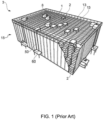
- the storage system 3 includes a plurality of robots 1 configured to move on dedicated supporting rails 13 and to receive a storage bin 2 from a storage column 8 within a bin storing grid 15.
- the prior art storage system 3 may also include a dedicated bin lift device 50, the latter being arranged to receive a storage bin 2 from the robot 1 at the top level of the storage system 3 and to convey the storage bin 2 down in a vertical direction to a delivery station, or port 60.
- EP 2 308 778 A2 discloses a method and a system for exchanging batteries incorporated in shuttles operating in warehouses and lifting pallets.
- the invention concerns a remotely operated vehicle assembly for picking up storage bins from a storage system, comprising a vehicle body which displays a cavity for receiving a storage bin situated somewhere within the storage system, a vehicle lifting device at least indirectly connected to the vehicle body for lifting the storage bin into the cavity, driving means connected to the vehicle body allowing remotely controlled movements of the vehicle assembly within the storage system, wireless communication means for providing wireless communication between the vehicle assembly and a remote control unit such as a computer, one or more main power sources supplying electrical power to the driving means and vehicle coupling means for operational and releasable coupling of the main power source to the vehicle body.
- Operational coupling is defined as a coupling that ensures power flow between the power source and the driving means.
- the coupling means is configured to allow automatic interchange / transfer of the main power source to a charging station after receiving at least one communication signal from the control unit, i.e. a transfer performed without any needs of human intervention.
- the vehicle assembly further comprises one or more auxiliary power sources for supplying electrical power to the driving means.
- This or these auxiliary power source(s) may be operated in addition to, or in absence of, one, several, or all of the main power sources.
- the vehicle assembly further comprises a management system for managing at least one of the power sources.
- a management system comprises means for monitoring at least one of voltage, temperature, state of charge, depth of discharge, state of health, coolant flow and current, and/or recharging controlling means for controlling at least one parameter related to recharging of at least one of the power sources such as one or more of the above mentioned monitoring parameters.
- the minimum amount of power stored in the auxiliary power source(s) equals the power required to move the vehicle assembly from one charging station to an adjacent charging station during operation.
- the one or more auxiliary power sources and the one or more main power sources are interconnected such that the main power source(s) may charge the auxiliary power source(s) while the main power source(s) provides electrical power to the vehicle.
- At least one of the power sources i.e. at least one of the main power sources and/or at least one of the auxiliary power sources, is a capacitor, for example a supercapacitor such as a double-layer capacitor, a pseudocapacitor and/or a hybrid capacitor.
- a capacitor for example a supercapacitor such as a double-layer capacitor, a pseudocapacitor and/or a hybrid capacitor.
- the at least one of the power sources i.e. at least one of the main power sources and/or at least one of the auxiliary power sources
- the at least one of the power sources is a rechargeable battery.
- rechargeable batteries are Lithium-Ion battery, Nickel-Cadmium battery, Nickel-Metal Hydride battery, Lithium-Ion Polymer battery, Lithium Sulfur battery, Thin Film battery, Smart battery Carbon Foam-based Lead Acid battery, Potassium-Ion battery, Sodium-Ion battery or a combination thereof.
- the vehicle assembly may further comprise a battery management system (BMS) in the form of a printed circuit board managing / controlling for example the charge to at least one of the power sources. This BMS is advantageously operatively arranged at or within the main power source.
- BMS battery management system
- the main power source comprises a receiving means enabling releasable connection to a corresponding charge station connection means situated on a charge station, where at least one of the receiving means may advantageously be a hook receiving means such as a recess, an aperture or a hank, allowing releasable connection with a corresponding pivotable charge station hook situated on a charge station.
- vehicle connection means further comprises at least one battery hook pivotable connected to the vehicle body, enabling releasable connection between the main power source(s) and the vehicle body.
- the invention also concerns a storage system for storage of bins, for example a storage system having a structure similar to the structure disclosed in detail in Norwegian patent application NO20121488 .
- the system comprises
- the invention furthermore concerns a method for charging a power source arranged in, near or on a remotely operated vehicle.
- a method for charging a power source arranged in, near or on a remotely operated vehicle comprises the following steps:
- the charging stations are preferably arranged on an underlying support onto which the vehicle assembly is moving.
- the lowering and raising of the vehicle body is achieved by elongation means connected to, or being an integral part of, the driving means.
- the method steps are controlled by transmitting communication signals between a control unit and a wireless communication means within the vehicle.
- the vehicle assembly used in the method may advantageously be of the type as disclosed above.
- Fig. 2 and 3 give perspective views in two different angles of a robot 1 comprising a rectangular vehicle body or framework 4 displaying a cavity 7 centrally arranged there within, a top lid 72 covering the top part of the body 4, a first set of four wheels 10 mounted inside the cavity 7 and a second set of four wheels 11 mounted at the exterior walls of the body 4.
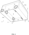
- the first and second set of wheels 10,11 are oriented perpendicular to each other.
- a Cartesian coordinate system is shown with its X, Y and Z axes aligned along the principal directions of the rectangular vehicle body 4.
- the size of the cavity 7 is adapted to contain necessary component for a lifting device 9 (see figure 4 ) and to contain the largest storage bin 2 intended to be picked up by the robot 1.
- Fig. 4 shows a part of a storage system 2 where the robot 1 is in a lifting position on a vehicle support 14, directly above a storage column 8 within a supporting bin storing structure 15.
- a vehicle lifting device 9 is lowered a distance into the storage column 8 in order to hook onto and lift up any storage bin 2 within the column 8.
- All operations of the robot 1 are controlled by wireless communication means 19 and remote control units. This includes control of the robot movement, the vehicle lifting device 9 and any vehicle position measurements.
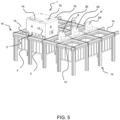
- the robot 1 is in fig. 5 shown arranged on a vehicle support 14 composed of a plurality of supporting rails 13, which vehicle support 14 is supported on a bin storing structure 15 constituting a plurality of storage columns 8.
- the robot 1 of fig. 5 comprises a main battery 6, battery holding means 22-24 for holding a main battery 6 during operation, as well as enabling flow of necessary power to the robots 1 driving means 10,11, an enclosing cover 73 with handles 74 and a control panel 75.
- the inventive storage system 3 further comprises several charging stations 20,20' being fixed to the vehicle support 14 in positions that are accessible for the part of the vehicle body 4 including the main battery 6 and/or the robot connection means 22-24.
- Each charging station 20, 20' comprises corresponding station connection means 25,26 which aids in the transfer of the main battery 6, as well as ensure stable connection and electrical charging.
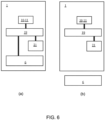
- Fig. 5 shows the particular situation where the robot 1 is approaching the charging station 20 in order to transfer an almost discharged main battery 6 to a battery vacant charging station 20. After a successful transfer, the robot 1 is moved to another charging station 20', typically being the closest charging station 20' that contains a main battery 6 being charged to a fully operational level. Such a movement from a first charging station 20 to a second charging station 20' along the vehicle support 14 is ensured by means of an auxiliary power source or battery 21 as schematically indicated in the block diagram of fig. 6 , where fig.
- FIG. 6 (a) and 6 (b) shows the robot 1 having the main battery connected and disconnected, respectively.
- the terminals of the main battery 6 are electrically connected to circuit board 19, which again is controlling the power flow to the driving means 10,11.
- driving means 10,11 includes all mechanisms and/or components within the robot 1 that at least ensures lateral movements, including wheels, motor, gears, etc.
- both fig. 6 (a) and 6 (b) indicates the above mentioned auxiliary battery 21, which terminals are electrically connected to the same circuit board 19 as the main battery 6.
- the robot 1 may with this configuration provide sufficient power to the driving means 10,11 to allow operation (lateral movements, elevations, operation of lifting device 9) of the robot 1 even in the complete (physical and/or electrical) absence of the main battery 6 ( fig. 6 (b) ).
- the auxiliary battery 21 may either remain electrically disconnected or function as an additional power source during the continuous operation of the robot 1.
- Fig. 7 is a cross sectional view of a robot 1 and a charging station 20 arranged on top of the vehicle support 14, showing in further details the location of the main battery 6, in this embodiment arranged within a dedicated main battery cavity 24, and the components constituting the robot holding means 22,23 on the side of the robot 1 and the station holding means 25 on the side of the charging station 20.
- the robot connection means 22,23 are illustrated as at least one robot hook 22 pivotably fixed to the side walls of the main battery cavity 24, thereby fixing the main battery 6 in position, and at least one robot aperture 23 present at the side of the main battery 6 facing the charging station 20,20'.
- the side of the charging station 20,20' facing the robot 1 comprises at least one pivotable charge station hook 25 that may be releasably fastened to the robot aperture(s) 23 and at least one charge station aperture that may be releasably receiving the pivotable robot hook(s) 22.
- the robot 1 is in the lateral position shown in fig. 7 adjustable in vertical direction, i.e. perpendicular to the vehicle support 14, to ensure reliable and easy fastening of the robot and charge station hooks 22,25 into their respective robot and charge station apertures 23.
- This movement is further detailed in fig. 8 which illustrates four different stages (a)-(d) of the main battery transfer process from the robot 1 to the charging station 20,20'. In the first stage ( fig.
- the robot 1 containing the main battery 6 is approaching the charging station 20,20' in an elevated position.
- the charge station situated charge station hooks 25 are being guided into their corresponding main battery situated robot apertures 23.
- the robot 1 is subsequently lowered a predetermined distance towards the underlying vehicle support 14 ( fig. 8 (c) ), resulting in a release of the robot hooks 22 from the main battery 6.
- the robot 1 is retracted away from the charging station 20,20' using the auxiliary power source 22 while remaining in the lowered position ( fig. 8 (d) .
- the robot 1 may then regain the elevated position and move along the vehicle support 14 to a charging station 20' with a sufficiently charged main battery 6.
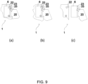
- Fig. 9 (a)-(c) presents an even more detailed presentation of the main battery transfer process from the robot 1 to the charging station 20.
- Fig. 9 (a) corresponds to the situation depicted in Fig. 8 (b) , that is, when the elevated robot 1 has been moved to a transfer position relative to the charging station 20 and the charge station hook 25 has been successfully guided and hooked to the corresponding robot aperture 23.
- fig. 9 (b) corresponds to the situation depicted in Fig. 8 (c) , when the robot 1 has been lowered, thereby releasing the robot hook 22 from the main battery 6.
- fig. 9 (c) corresponds to the situation depicted in Fig. 8 (d) , when the robot 1 has been retracted from the charging station 20 by means of the auxiliary power source 21, leaving the main battery in a charging connection to the charging station 20.
Landscapes
- Engineering & Computer Science (AREA)
- Mechanical Engineering (AREA)
- Power Engineering (AREA)
- Transportation (AREA)
- Mathematical Physics (AREA)
- Physics & Mathematics (AREA)
- Sustainable Energy (AREA)
- Sustainable Development (AREA)
- Life Sciences & Earth Sciences (AREA)
- Charge And Discharge Circuits For Batteries Or The Like (AREA)
- Electric Propulsion And Braking For Vehicles (AREA)
- Warehouses Or Storage Devices (AREA)
- Automobile Manufacture Line, Endless Track Vehicle, Trailer (AREA)
- Platform Screen Doors And Railroad Systems (AREA)
- Stand-By Power Supply Arrangements (AREA)
- Control Of Position, Course, Altitude, Or Attitude Of Moving Bodies (AREA)
Description
- The present invention relates to a remotely operated vehicle for picking up storage bins from a storage system as defined in the preamble of
claim 1, a storage system for storage of bins and a method for changing a power source. - A remotely operated vehicle for picking up storage bins from a storage system is known. A detailed description of a relevant prior art storage system is presented in
WO 98/49075 NO317366 - An example of a prior art storage system art is illustrated in
figure 1 . Thestorage system 3 includes a plurality ofrobots 1 configured to move on dedicated supportingrails 13 and to receive astorage bin 2 from astorage column 8 within a bin storinggrid 15. The priorart storage system 3 may also include a dedicatedbin lift device 50, the latter being arranged to receive astorage bin 2 from therobot 1 at the top level of thestorage system 3 and to convey thestorage bin 2 down in a vertical direction to a delivery station, orport 60. - However, with this known system there is an undesired robot standstill due to the need of recharge, thereby reducing the operational cycle of the
storage system 3 as a whole to typically 16 hours per day. Inaddition EP 2 308 778 A2 discloses a method and a system for exchanging batteries incorporated in shuttles operating in warehouses and lifting pallets. - It is thus an object of the present invention to provide a solution that enables a significant increase in the overall operational cycle, preferably close to 24 hours per day.
- The present invention is set forth and characterized in the main claims, while the dependent claims describe other characteristics of the invention.
- In particular, the invention concerns a remotely operated vehicle assembly for picking up storage bins from a storage system, comprising a vehicle body which displays a cavity for receiving a storage bin situated somewhere within the storage system, a vehicle lifting device at least indirectly connected to the vehicle body for lifting the storage bin into the cavity, driving means connected to the vehicle body allowing remotely controlled movements of the vehicle assembly within the storage system, wireless communication means for providing wireless communication between the vehicle assembly and a remote control unit such as a computer, one or more main power sources supplying electrical power to the driving means and vehicle coupling means for operational and releasable coupling of the main power source to the vehicle body. Operational coupling is defined as a coupling that ensures power flow between the power source and the driving means.
- According to the invention the coupling means is configured to allow automatic interchange / transfer of the main power source to a charging station after receiving at least one communication signal from the control unit, i.e. a transfer performed without any needs of human intervention.
- According to the invention the vehicle assembly further comprises one or more auxiliary power sources for supplying electrical power to the driving means. This or these auxiliary power source(s) may be operated in addition to, or in absence of, one, several, or all of the main power sources.
- In another preferred embodiment the vehicle assembly further comprises a management system for managing at least one of the power sources. Such a management system comprises means for monitoring at least one of voltage, temperature, state of charge, depth of discharge, state of health, coolant flow and current, and/or recharging controlling means for controlling at least one parameter related to recharging of at least one of the power sources such as one or more of the above mentioned monitoring parameters.
- In another preferred embodiment the minimum amount of power stored in the auxiliary power source(s) equals the power required to move the vehicle assembly from one charging station to an adjacent charging station during operation.
- In another preferred embodiment the one or more auxiliary power sources and the one or more main power sources are interconnected such that the main power source(s) may charge the auxiliary power source(s) while the main power source(s) provides electrical power to the vehicle.
- In another preferred embodiment at least one of the power sources, i.e. at least one of the main power sources and/or at least one of the auxiliary power sources, is a capacitor, for example a supercapacitor such as a double-layer capacitor, a pseudocapacitor and/or a hybrid capacitor.
- In another preferred embodiment the at least one of the power sources, i.e. at least one of the main power sources and/or at least one of the auxiliary power sources, is a rechargeable battery. Examples of rechargeable batteries are Lithium-Ion battery, Nickel-Cadmium battery, Nickel-Metal Hydride battery, Lithium-Ion Polymer battery, Lithium Sulfur battery, Thin Film battery, Smart battery Carbon Foam-based Lead Acid battery, Potassium-Ion battery, Sodium-Ion battery or a combination thereof. In order to monitor and control the performance of the at least one battery the vehicle assembly may further comprise a battery management system (BMS) in the form of a printed circuit board managing / controlling for example the charge to at least one of the power sources. This BMS is advantageously operatively arranged at or within the main power source.
- In another preferred embodiment the main power source comprises a receiving means enabling releasable connection to a corresponding charge station connection means situated on a charge station, where at least one of the receiving means may advantageously be a hook receiving means such as a recess, an aperture or a hank, allowing releasable connection with a corresponding pivotable charge station hook situated on a charge station.
- In another preferred embodiment the vehicle connection means further comprises at least one battery hook pivotable connected to the vehicle body, enabling releasable connection between the main power source(s) and the vehicle body.
- The invention also concerns a storage system for storage of bins, for example a storage system having a structure similar to the structure disclosed in detail in Norwegian patent application
NO20121488 - one or more remotely operated vehicles in accordance with the above disclosed vehicle,
- one or more charging stations,
- a vehicle support comprising a plurality of supporting rails and
- a bin storing structure supporting the vehicle support, and containing a plurality of storage columns, wherein each storage columns is arranged to accommodate a vertical stack of storage bins. The main part of the bin storing structure coincides with positions on the vehicle support in which the supporting rails are crossing.
- The invention furthermore concerns a method for charging a power source arranged in, near or on a remotely operated vehicle. Such a method comprises the following steps:
- a) moving the remotely operated vehicle assembly to a charging position adjacent to a first charging station,
- b) transferring a first main power source connected to a vehicle body of the vehicle assembly to the first charging station,
- c) moving the vehicle assembly to a second charging station using an auxiliary power source supplying auxiliary electrical power to driving means and
- d) transferring a second main power source connected to the second charging station to the vehicle body, the second main power source having been charged for a time period by the second charging station.
- The charging stations are preferably arranged on an underlying support onto which the vehicle assembly is moving.
- The lowering and raising of the vehicle body is achieved by elongation means connected to, or being an integral part of, the driving means.
- In another preferred embodiment the method steps are controlled by transmitting communication signals between a control unit and a wireless communication means within the vehicle.
- The vehicle assembly used in the method may advantageously be of the type as disclosed above.
- In the following description, numerous specific details are introduced to provide a thorough understanding of embodiments of the claimed vehicle, system and method. One skilled in the relevant art, however, will recognize that these embodiments can be practiced without one or more of the specific details, or with other components, systems, etc. In other instances, well-known structures or operations are not shown, or are not described in detail, to avoid obscuring aspects of the disclosed embodiments.
-
-
Fig. 1 is a perspective view of a prior art storage system; -
Fig. 2 is a perspective base view of a remotely operated vehicle according to the invention; -
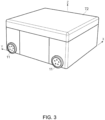
Fig. 3 is a perspective top view of a remotely operated vehicle according to the invention; -
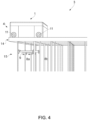
Fig. 4 is a perspective side view of part of a storage system in accordance with the invention including a bin storing grid, a vehicle support and a robot; -
Fig. 5 is a perspective side view of part of a storage system in accordance with the invention including a bin storing grid, a vehicle support, a robot and a plurality of charging stations; -
Figure 6 is a block diagram of a robot showing a main power source and an auxiliary power source, whereinfigure 6 (a) and (b) shows the main power source being operationally connected to, and disconnected from, the robot, respectively, -
Figure 7 is a cross sectional view of a robot and a charging station, -
Figures 8 (a)-(d) are cross sectional views of a robot and a charging station, whereinfigure 8 (a) shows a battery containing robot in a raised position and at a distance from its charging position,figures 8 (b) and 8 (c) show a battery containing robot in a raised position and a lowered position, respectively, situated adjacent to its charging position andfigure 8 (d) shows the robot in a lowered position at a distance from its charging position after transfer of the battery to the charging station and, -
Figures 9 (a)-(c) are cross sectional cut-outs providing further details of the connection mechanisms infigures 8 (b)-(d) , whereinfigures 9 (a) and (b) show connecting hooks on the robot and the charging stations in raised and lowered position, respectively, andfigure 9 (c) shows the connecting hooks after successful connection of the battery to the charging station. -
Fig. 2 and3 give perspective views in two different angles of arobot 1 comprising a rectangular vehicle body orframework 4 displaying acavity 7 centrally arranged there within, atop lid 72 covering the top part of thebody 4, a first set of fourwheels 10 mounted inside thecavity 7 and a second set of fourwheels 11 mounted at the exterior walls of thebody 4. The first and second set ofwheels rectangular vehicle body 4. The size of thecavity 7 is adapted to contain necessary component for a lifting device 9 (seefigure 4 ) and to contain thelargest storage bin 2 intended to be picked up by therobot 1. -
Fig. 4 shows a part of astorage system 2 where therobot 1 is in a lifting position on avehicle support 14, directly above astorage column 8 within a supportingbin storing structure 15. Avehicle lifting device 9 is lowered a distance into thestorage column 8 in order to hook onto and lift up anystorage bin 2 within thecolumn 8. - All operations of the
robot 1 are controlled by wireless communication means 19 and remote control units. This includes control of the robot movement, thevehicle lifting device 9 and any vehicle position measurements. - As in
fig. 4 therobot 1 is infig. 5 shown arranged on avehicle support 14 composed of a plurality of supportingrails 13, whichvehicle support 14 is supported on abin storing structure 15 constituting a plurality ofstorage columns 8. Therobot 1 offig. 5 comprises amain battery 6, battery holding means 22-24 for holding amain battery 6 during operation, as well as enabling flow of necessary power to therobots 1 driving means 10,11, an enclosingcover 73 withhandles 74 and acontrol panel 75. In order to allow charging of themain battery 6 theinventive storage system 3 further comprises several chargingstations 20,20' being fixed to thevehicle support 14 in positions that are accessible for the part of thevehicle body 4 including themain battery 6 and/or the robot connection means 22-24. Each chargingstation 20, 20' comprises corresponding station connection means 25,26 which aids in the transfer of themain battery 6, as well as ensure stable connection and electrical charging.Fig. 5 shows the particular situation where therobot 1 is approaching the chargingstation 20 in order to transfer an almost dischargedmain battery 6 to a battery vacant chargingstation 20. After a successful transfer, therobot 1 is moved to another charging station 20', typically being the closest charging station 20' that contains amain battery 6 being charged to a fully operational level. Such a movement from a first chargingstation 20 to a second charging station 20' along thevehicle support 14 is ensured by means of an auxiliary power source orbattery 21 as schematically indicated in the block diagram offig. 6 , wherefig. 6 (a) and 6 (b) shows therobot 1 having the main battery connected and disconnected, respectively. When connected, the terminals of themain battery 6 are electrically connected tocircuit board 19, which again is controlling the power flow to the driving means 10,11. Note that driving means 10,11 includes all mechanisms and/or components within therobot 1 that at least ensures lateral movements, including wheels, motor, gears, etc. Furthermore, bothfig. 6 (a) and 6 (b) indicates the above mentionedauxiliary battery 21, which terminals are electrically connected to thesame circuit board 19 as themain battery 6. As a result therobot 1 may with this configuration provide sufficient power to the driving means 10,11 to allow operation (lateral movements, elevations, operation of lifting device 9) of therobot 1 even in the complete (physical and/or electrical) absence of the main battery 6 (fig. 6 (b) ). When themain battery 6 is connected, theauxiliary battery 21 may either remain electrically disconnected or function as an additional power source during the continuous operation of therobot 1. -
Fig. 7 is a cross sectional view of arobot 1 and a chargingstation 20 arranged on top of thevehicle support 14, showing in further details the location of themain battery 6, in this embodiment arranged within a dedicatedmain battery cavity 24, and the components constituting the robot holding means 22,23 on the side of therobot 1 and the station holding means 25 on the side of the chargingstation 20. The robot connection means 22,23 are illustrated as at least onerobot hook 22 pivotably fixed to the side walls of themain battery cavity 24, thereby fixing themain battery 6 in position, and at least onerobot aperture 23 present at the side of themain battery 6 facing the chargingstation 20,20'. Likewise, the side of the chargingstation 20,20' facing therobot 1 comprises at least one pivotablecharge station hook 25 that may be releasably fastened to the robot aperture(s) 23 and at least one charge station aperture that may be releasably receiving the pivotable robot hook(s) 22. Therobot 1 is in the lateral position shown infig. 7 adjustable in vertical direction, i.e. perpendicular to thevehicle support 14, to ensure reliable and easy fastening of the robot and charge station hooks 22,25 into their respective robot andcharge station apertures 23. This movement is further detailed infig. 8 which illustrates four different stages (a)-(d) of the main battery transfer process from therobot 1 to the chargingstation 20,20'. In the first stage (fig. 8 (a) ) therobot 1 containing themain battery 6 is approaching the chargingstation 20,20' in an elevated position. When therobot 1 is in the lateral transfer position relative to the chargingstation 20,20' (fig. 8 (b) ) the charge station situated charge station hooks 25 are being guided into their corresponding main battery situatedrobot apertures 23. Therobot 1 is subsequently lowered a predetermined distance towards the underlying vehicle support 14 (fig. 8 (c) ), resulting in a release of the robot hooks 22 from themain battery 6. Finally therobot 1 is retracted away from the chargingstation 20,20' using theauxiliary power source 22 while remaining in the lowered position (fig. 8 (d) . Therobot 1 may then regain the elevated position and move along thevehicle support 14 to a charging station 20' with a sufficiently chargedmain battery 6. -
Fig. 9 (a)-(c) presents an even more detailed presentation of the main battery transfer process from therobot 1 to the chargingstation 20.Fig. 9 (a) corresponds to the situation depicted inFig. 8 (b) , that is, when theelevated robot 1 has been moved to a transfer position relative to the chargingstation 20 and thecharge station hook 25 has been successfully guided and hooked to thecorresponding robot aperture 23. Further,fig. 9 (b) corresponds to the situation depicted inFig. 8 (c) , when therobot 1 has been lowered, thereby releasing therobot hook 22 from themain battery 6. And finally,fig. 9 (c) corresponds to the situation depicted inFig. 8 (d) , when therobot 1 has been retracted from the chargingstation 20 by means of theauxiliary power source 21, leaving the main battery in a charging connection to the chargingstation 20. - In the preceding description, various aspects of the apparatus according to the invention have been described with reference to the illustrative embodiment. For purposes of explanation, specific numbers, systems and configurations were set forth in order to provide a thorough understanding of the apparatus and its workings. However, this description is not intended to be construed in a limiting sense. Various modifications and variations of the illustrative embodiment, as well as other embodiments of the apparatus, which are apparent to persons skilled in the art to which the disclosed subject matter pertains, are deemed to lie within the scope of the claims.
-
- 1
- Remotely operated vehicle assembly / robot
- 2
- Storage bin
- 3
- Storage system
- 4
- Vehicle body / framework
- 6
- Main power source / main battery
- 7
- Cavity
- 8
- Storage column
- 9
- Vehicle lifting device
- 10
- First set of vehicle rolling means / first set of wheels / driving means
- 11
- Second set of vehicle rolling means / second set of wheels / driving means
- 13
- Supporting rail
- 14
- Vehicle support
- 15
- Bin storing structure / bin storing grid
- 19
- Circuit board / management system / battery management system
- 20
- Charging station / first charging station
- 20'
- Adjacent charging station / second charging station
- 21
- Auxiliary power source / auxiliary battery
- 22
- Vehicle connection means / robot hook
- 23
- Receiving means / robot aperture
- 24
- Main battery cavity
- 25
- Charge station connection means / charge station hook
- 50
- Bin lift device
- 60
- Delivery station / port
- 72
- Top lid
- 73
- Enclosing cover
- 74
- Handles
- 75
- Wireless communication means / control panel
Claims (12)
- A remotely operated vehicle assembly (1) for picking up storage bins (2) from an underlying storage system (3), comprisinga vehicle body (4) displaying a cavity (7) for receiving a storage bin (2) within the storage system (3),a vehicle lifting device (9) at least indirectly connected to the vehicle body (4) for vertically lifting the storage bin (2) from the underlying storage system (3) into the cavity (7),driving means (10,11) connected to the vehicle body (4) allowing remotely controlled movements of the vehicle assembly (1) within the storage system (3) andwireless communication means (75) for providing wireless communication between the vehicle assembly (1) and a remote control unit,a rechargeable main power source (6) supplying electrical power to the driving means (10,11) characterized in that the vehicle assembly further comprises:vehicle coupling means (22) for releasable coupling the main power source (6) to the vehicle body (4),wherein said coupling means (22) is configured to allow interchange of the main power source (6) to a stationary charging station (20) after receiving at least one communication signal from the control unit and wherein the vehicle assembly (1) further comprises an auxiliary power source (21) for supplying electrical power to the driving means (10,11).
- The vehicle assembly (1) in accordance with claim 1,characterized in that at the vehicle assembly (1) further comprising a management system (19) for managing at least one of the power sources (6,21),said management system (19) comprisingmeans for monitoring at least one of voltage, temperature, state of charge (SOC), depth of discharge (DOD), state of health (SOH), coolant flow and current andrecharging controlling means for controlling at least one parameter related to recharging of at least one of the power sources (6,21).
- The vehicle assembly (1) in accordance with claim 2,
characterized in that, during the operation of the vehicle (1), the minimum amount of power stored in the auxiliary power source (21) equals the power required to move the vehicle assembly (1) from one charging station (20) to an adjacent charging station (20'). - The vehicle assembly (1) in accordance with claim 2 or 3, characterized in that the auxiliary power source (21) and the main power source (6) are interconnected such that the main power source (6) may charge the auxiliary power source (21) when the main power source (6) is operationally connected to the vehicle assembly (1).
- The vehicle assembly (1) in accordance with one of the preceding claims, characterized in that at least one of the power sources (6,21) is a capacitor.
- 7. The vehicle assembly (1) in accordance with one of the preceding claims, characterized in that at least one of the power sources (6,21) is a rechargeable battery.
- The vehicle assembly (1) in accordance with one of claim 6, characterized in that the vehicle assembly (1) further comprising a battery management system (BMS) (19) managing at least one of the power sources (6,21).
- The vehicle assembly (1) in accordance with one of the preceding claims, characterized in that the main power source (6) comprising
a receiving means (23) enabling releasable connection to a corresponding charge station connection means (25) situated on a charge station (20,20'). - The vehicle assembly (1) in accordance with claim 8, characterized in that at least one of the receiving means (23) is a hook receiving means.
- The vehicle assembly (1) in accordance with one of the preceding claims, characterized in that the vehicle connection means (22) further comprising
at least one battery hook (22) pivotable connected to the vehicle body (4), enabling releasable connection between the main power source (6) and the vehicle body (4). - Storage system (3) for storage of bins (2), characterized by comprising- a remotely operated vehicle assembly (1) in accordance with any of claims 1-10,- a charging station (20,20'),- a vehicle support (14) and- a bin storing structure (15) supporting the vehicle support (14), the structure (15) comprising a plurality of storage columns (8,8a,8b), wherein
each storage columns (8,8a,8b) is arranged to accommodate a vertical stack of storage bins (2). - Method for charging a power source (6,6') arranged in a remotely operated vehicle assembly (1), the method comprising the following steps:a) moving the remotely operated vehicle assembly (1) to a charging position adjacent to a first charging station (20),b) transferring a first main power source (6) connected to a vehicle body (4) of the vehicle assembly (1) to the first charging station (20),c) moving the vehicle assembly (1) to a second charging station (20') using an auxiliary power source (21) supplying auxiliary electrical power to driving means (10,11) andd) transferring a second main power source (6') connected to the second charging station (20') to the vehicle body (4), the second main power source (6') having been charged for a time period (T) by the second charging station (20).
Priority Applications (3)
| Application Number | Priority Date | Filing Date | Title |
|---|---|---|---|
| EP24220263.8A EP4534331A3 (en) | 2014-01-08 | 2015-01-06 | Robot for transporting storage bins |
| PL15700422.7T PL3092187T5 (en) | 2014-01-08 | 2015-01-06 | Robot for transporting underlying bins with interchangeable main power source |
| EP21173167.4A EP3882182B1 (en) | 2014-01-08 | 2015-01-06 | Robot for transporting storage bins |
Applications Claiming Priority (2)
| Application Number | Priority Date | Filing Date | Title |
|---|---|---|---|
| NO20140015A NO340313B1 (en) | 2014-01-08 | 2014-01-08 | Remote controlled vehicle for picking up storage containers from a storage system, storage system for storage of containers and method for replacing a power source |
| PCT/EP2015/050103 WO2015104263A2 (en) | 2014-01-08 | 2015-01-06 | Robot for transporting storage bins |
Related Child Applications (3)
| Application Number | Title | Priority Date | Filing Date |
|---|---|---|---|
| EP21173167.4A Division EP3882182B1 (en) | 2014-01-08 | 2015-01-06 | Robot for transporting storage bins |
| EP21173167.4A Division-Into EP3882182B1 (en) | 2014-01-08 | 2015-01-06 | Robot for transporting storage bins |
| EP24220263.8A Division EP4534331A3 (en) | 2014-01-08 | 2015-01-06 | Robot for transporting storage bins |
Publications (3)
| Publication Number | Publication Date |
|---|---|
| EP3092187A2 EP3092187A2 (en) | 2016-11-16 |
| EP3092187B1 EP3092187B1 (en) | 2021-07-28 |
| EP3092187B2 true EP3092187B2 (en) | 2024-06-12 |
Family
ID=52354957
Family Applications (3)
| Application Number | Title | Priority Date | Filing Date |
|---|---|---|---|
| EP15700422.7A Active EP3092187B2 (en) | 2014-01-08 | 2015-01-06 | Robot for transporting underlying bins with interchangeable main power source |
| EP24220263.8A Pending EP4534331A3 (en) | 2014-01-08 | 2015-01-06 | Robot for transporting storage bins |
| EP21173167.4A Active EP3882182B1 (en) | 2014-01-08 | 2015-01-06 | Robot for transporting storage bins |
Family Applications After (2)
| Application Number | Title | Priority Date | Filing Date |
|---|---|---|---|
| EP24220263.8A Pending EP4534331A3 (en) | 2014-01-08 | 2015-01-06 | Robot for transporting storage bins |
| EP21173167.4A Active EP3882182B1 (en) | 2014-01-08 | 2015-01-06 | Robot for transporting storage bins |
Country Status (17)
| Country | Link |
|---|---|
| US (1) | US9821959B2 (en) |
| EP (3) | EP3092187B2 (en) |
| JP (2) | JP6978202B2 (en) |
| CN (1) | CN105899398B (en) |
| AU (1) | AU2015205653A1 (en) |
| CA (1) | CA2934020C (en) |
| CL (1) | CL2016001735A1 (en) |
| DK (1) | DK3092187T4 (en) |
| EA (1) | EA201691338A1 (en) |
| ES (1) | ES2883569T5 (en) |
| HK (1) | HK1223888A1 (en) |
| MX (1) | MX375523B (en) |
| NO (1) | NO340313B1 (en) |
| PL (1) | PL3092187T5 (en) |
| SG (1) | SG11201605571YA (en) |
| TW (1) | TW201529448A (en) |
| WO (1) | WO2015104263A2 (en) |
Families Citing this family (145)
| Publication number | Priority date | Publication date | Assignee | Title |
|---|---|---|---|---|
| NO335839B1 (en) * | 2012-12-10 | 2015-03-02 | Jakob Hatteland Logistics As | Robot for transporting storage containers |
| US9139363B2 (en) | 2013-03-15 | 2015-09-22 | John Lert | Automated system for transporting payloads |
| GB201404870D0 (en) * | 2014-03-18 | 2014-04-30 | Ocado Ltd | Robotic service device and handling method |
| EP2995958A1 (en) | 2014-09-15 | 2016-03-16 | Roche Diagniostics GmbH | Method of operating a laboratory sample distribution system, laboratory sample distribution system and laboratory automation system |
| US12366043B2 (en) | 2015-03-06 | 2025-07-22 | Walmart Apollo, Llc | Overriding control of motorized transport unit systems, devices and methods |
| US20160255969A1 (en) | 2015-03-06 | 2016-09-08 | Wal-Mart Stores, Inc. | Shopping facility assistance systems, devices and methods pertaining to movement of a mobile retail product display |
| US12084824B2 (en) | 2015-03-06 | 2024-09-10 | Walmart Apollo, Llc | Shopping facility assistance systems, devices and methods |
| US20180099846A1 (en) | 2015-03-06 | 2018-04-12 | Wal-Mart Stores, Inc. | Method and apparatus for transporting a plurality of stacked motorized transport units |
| WO2016142794A1 (en) | 2015-03-06 | 2016-09-15 | Wal-Mart Stores, Inc | Item monitoring system and method |
| EP3283700B1 (en) | 2015-04-15 | 2020-01-15 | Ocado Innovation Limited | System and method for configuration of buildings or storage |
| GB2558798A (en) * | 2015-04-15 | 2018-07-18 | Ocado Innovation Ltd | System and method for configuration of self-storage |
| EP3096146A1 (en) | 2015-05-22 | 2016-11-23 | Roche Diagniostics GmbH | Method of operating a laboratory sample distribution system, laboratory sample distribution system and laboratory automation system |
| EP3650375A1 (en) | 2015-06-02 | 2020-05-13 | Alert Innovation Inc. | Storage and retrieval system |
| US11203486B2 (en) | 2015-06-02 | 2021-12-21 | Alert Innovation Inc. | Order fulfillment system |
| US11142398B2 (en) | 2015-06-02 | 2021-10-12 | Alert Innovation Inc. | Order fulfillment system |
| EP3112874A1 (en) | 2015-07-02 | 2017-01-04 | Roche Diagnostics GmbH | Storage module, method of operating a laboratory automation system and laboratory automation system |
| EP3121603A1 (en) | 2015-07-22 | 2017-01-25 | Roche Diagnostics GmbH | Sample container carrier, laboratory sample distribution system and laboratory automation system |
| CA2938587A1 (en) * | 2015-08-14 | 2017-02-14 | Wal-Mart Stores, Inc. | Shopping facility track system and method of routing motorized transport units |
| GB201523105D0 (en) | 2015-12-30 | 2016-02-10 | Hyperdrive Innovation Ltd | Battery management system |
| NO342469B1 (en) | 2016-02-01 | 2018-05-28 | Autostore Tech As | Cleaning bin for cleaning a storage grid of a storage system and method for the same |
| GB201602505D0 (en) * | 2016-02-12 | 2016-03-30 | Ocado Innovation Ltd | Storage systems,methods and containers |
| EP3211429A1 (en) | 2016-02-26 | 2017-08-30 | Roche Diagnostics GmbH | Transport device having a tiled driving surface |
| EP3211430A1 (en) | 2016-02-26 | 2017-08-30 | Roche Diagnostics GmbH | Transport device with base plate modules |
| EP3211428A1 (en) | 2016-02-26 | 2017-08-30 | Roche Diagnostics GmbH | Transport device unit for a laboratory sample distribution system |
| GB201603518D0 (en) | 2016-02-29 | 2016-04-13 | Ocado Innovation Ltd | Robotic fire extinguishing device and handling method |
| GB201603520D0 (en) * | 2016-02-29 | 2016-04-13 | Ocado Innovation Ltd | Robotic service device and handling method |
| GB201604100D0 (en) | 2016-03-10 | 2016-04-20 | Ocado Innovation Ltd | Apparatus for retrieving units from a storage system |
| CA2961938A1 (en) | 2016-04-01 | 2017-10-01 | Wal-Mart Stores, Inc. | Systems and methods for moving pallets via unmanned motorized unit-guided forklifts |
| CN109196363A (en) | 2016-06-03 | 2019-01-11 | 豪夫迈·罗氏有限公司 | Laboratory sample distribution system and laboratory automation system |
| EP3255519B1 (en) | 2016-06-09 | 2019-02-20 | Roche Diagniostics GmbH | Laboratory sample distribution system and method of operating a laboratory sample distribution system |
| NO344308B1 (en) * | 2016-06-21 | 2019-10-28 | Autostore Tech As | Storage system comprising a charging station assembly and method of replacing the power source of a remotely operated vehicle |
| NO341951B1 (en) | 2016-06-30 | 2018-03-05 | Autostore Tech As | Operating method of a communication node in a storage system |
| EP3494398B1 (en) | 2016-08-04 | 2022-04-06 | Roche Diagnostics GmbH | Laboratory sample distribution system and laboratory automation system |
| GB201617727D0 (en) * | 2016-10-19 | 2016-11-30 | Ocado Innovation Limited | Storage systems and methods |
| NO20161734A1 (en) * | 2016-11-02 | 2018-01-02 | Autostore Tech As | Track sensors for detecting position of vehicle relative to tracks |
| NO20161733A1 (en) | 2016-11-02 | 2018-03-19 | Autostore Tech As | Controlling movements of a robot running on tracks |
| WO2018094286A1 (en) | 2016-11-17 | 2018-05-24 | Alert Innovation Inc. | Automated-service retail system and method |
| CA3302758A1 (en) | 2016-11-29 | 2026-03-31 | Symbotic Llc | Automated retail supply chain and inventory management system |
| JP2020504066A (en) | 2017-01-10 | 2020-02-06 | アラート イノヴェイション インコーポレイテッド | Automatic store with exchangeable automatic mobile robot |
| NO343227B1 (en) * | 2017-01-30 | 2018-12-10 | Autostore Tech As | Remotely operated vehicle and storage system comprising such vehicle |
| EP3355065B1 (en) * | 2017-01-31 | 2021-08-18 | Roche Diagnostics GmbH | Laboratory sample distribution system and laboratory automation system |
| EP3357842B1 (en) | 2017-02-03 | 2022-03-23 | Roche Diagnostics GmbH | Laboratory automation system |
| USD897623S1 (en) | 2017-02-17 | 2020-09-29 | Autostore Technology AS | Dual track |
| JP7478320B2 (en) | 2017-02-24 | 2024-05-07 | ウォルマート アポロ リミテッド ライアビリティ カンパニー | Inventory control system and method |
| EP3601107A1 (en) | 2017-03-20 | 2020-02-05 | Berkshire Grey, Inc. | Systems and methods for processing objects including mobile matrix carrier systems |
| CA3057367C (en) | 2017-03-23 | 2023-01-10 | Berkshire Grey, Inc. | Systems and methods for processing objects, including automated mobile matrix bins |
| ES2973481T3 (en) | 2017-03-23 | 2024-06-20 | Berkshire Grey Operating Company Inc | System and method for processing objects, including automated mobile matrix carriers |
| JP6286084B1 (en) * | 2017-03-24 | 2018-02-28 | 本田技研工業株式会社 | Containment device |
| NO344463B1 (en) * | 2017-05-16 | 2019-12-23 | Autostore Tech As | Automated storage and retrieval system and method of operating same |
| NO346327B1 (en) * | 2017-05-16 | 2022-06-07 | Autostore Tech As | Automated storage and retrieval system |
| NO20180586A1 (en) | 2018-04-25 | 2019-10-28 | Autostore Tech As | Charging system for container handling vehicles and method of charging a power supply |
| PL3634885T3 (en) | 2017-05-16 | 2024-06-24 | Autostore Technology AS | Automated storage and retrieval system |
| US10384541B2 (en) * | 2017-05-19 | 2019-08-20 | UBTECH Robotics Corp. | Laser radar module and robot |
| EP3410123B1 (en) | 2017-06-02 | 2023-09-20 | Roche Diagnostics GmbH | Method of operating a laboratory sample distribution system, laboratory sample distribution system and laboratory automation system |
| EP3428653B1 (en) | 2017-07-13 | 2021-09-15 | Roche Diagnostics GmbH | Method of operating a laboratory sample distribution system, laboratory sample distribution system and laboratory automation system |
| EP3456415B1 (en) | 2017-09-13 | 2021-10-20 | Roche Diagnostics GmbH | Sample container carrier, laboratory sample distribution system and laboratory automation system |
| EP3457144B1 (en) | 2017-09-13 | 2021-10-20 | Roche Diagnostics GmbH | Sample container carrier, laboratory sample distribution system and laboratory automation system |
| NO343676B1 (en) * | 2017-09-20 | 2019-05-06 | Autostore Tech As | Container handling vehicle |
| CN114620398B (en) | 2017-10-27 | 2024-01-02 | 伯克希尔格雷营业股份有限公司 | object handling system |
| NO346519B1 (en) | 2017-11-02 | 2022-09-19 | Autostore Tech As | An automated storage and retrieval system, use of a multi trolley vehicle on the system and a method of operating the system |
| NO344326B1 (en) * | 2017-11-07 | 2019-11-04 | Autostore Tech As | Storage system comprising a charging station Assembly and a method for exchanging a power source of a vehicle operating in a storage system. |
| NO345129B1 (en) | 2017-11-23 | 2020-10-12 | Autostore Tech As | Automated storage and retrieval system and a method of operating the same. |
| CN108045754B (en) * | 2018-01-02 | 2024-01-26 | 上海木爷机器人技术有限公司 | A storage cabinet and a transport robot capable of charging the storage cabinet |
| NO346347B1 (en) * | 2018-04-25 | 2022-06-20 | Autostore Tech As | Container handling vehicle comprising first and second section and assembly of motors in second section, and system |
| NO346364B1 (en) * | 2018-04-25 | 2022-06-27 | Autostore Tech As | Container handling vehicle with first and second sections and battery in second section, and system. |
| US11479407B2 (en) | 2018-01-09 | 2022-10-25 | Autostore Technology AS | Displacement mechanism for a remotely operated vehicle |
| JP7289310B2 (en) * | 2018-02-08 | 2023-06-09 | アラート イノヴェイション インコーポレイテッド | Opportunistic charging system for automated storage and retrieval systems |
| EP3537159B1 (en) | 2018-03-07 | 2022-08-31 | Roche Diagnostics GmbH | Method of operating a laboratory sample distribution system, laboratory sample distribution system and laboratory automation system |
| KR102275879B1 (en) * | 2018-03-12 | 2021-07-08 | 주식회사 엘지에너지솔루션 | Auxiliary Battery storage device for Electric vehicle |
| EP3540443B1 (en) | 2018-03-16 | 2023-08-30 | Roche Diagnostics GmbH | Laboratory system, laboratory sample distribution system and laboratory automation system |
| US11377298B2 (en) | 2018-04-25 | 2022-07-05 | Autostore Technology AS | Container handling vehicle with first and second sections and lifting device motor in second section |
| GB201807562D0 (en) * | 2018-05-09 | 2018-06-20 | Ocado Innovation Ltd | Apparatus and method for charging a robotic load handling device |
| NO344889B1 (en) * | 2018-06-06 | 2020-06-15 | Autostore Tech As | A service vehicle, an automated storage and retrieval system using such a service vehicle and a method thereof |
| WO2019233749A1 (en) | 2018-06-06 | 2019-12-12 | Autostore Technology AS | Service vehicle for extinguishing fire on and within an automated storage and retrieval system and a method thereof |
| NO345886B1 (en) | 2018-06-12 | 2021-09-27 | Autostore Tech As | Vehicle tilting Device and Method of accessing a Storage container |
| EP4279420A3 (en) | 2018-06-12 | 2024-02-28 | Autostore Technology AS | Storage system |
| NO346644B1 (en) * | 2019-02-19 | 2022-11-14 | Autostore Tech As | A storage system, a container vehicle and a charging station for the storage system and a method of charging the container vehicle. |
| EP4545450A3 (en) | 2018-06-12 | 2025-07-09 | AutoStore Technology AS | System for storing and transporting storage containers |
| CA3099882A1 (en) | 2018-06-12 | 2019-12-19 | Autostore Technology AS | A method of operating an automated storage and retrieval system |
| CN114604545B (en) | 2018-06-12 | 2025-03-18 | 自动存储科技股份有限公司 | Remotely operated delivery vehicles |
| WO2019238702A1 (en) | 2018-06-12 | 2019-12-19 | Autostore Technology AS | Automated storage system with a container vehicle and a charging system |
| ES3054001T3 (en) * | 2018-06-12 | 2026-01-28 | Autostore Tech As | Automated storage system with a container vehicle and a charging system |
| EP3807184A1 (en) * | 2018-06-12 | 2021-04-21 | Autostore Technology As | Storage grid with container accessing station with locking device to lock remotely operated vehicle |
| NO344750B1 (en) | 2018-06-12 | 2020-04-06 | Autostore Tech As | Unloading arrangement and unloading station, as well as method of unloading an item from a storage container |
| NO344742B1 (en) | 2018-06-12 | 2020-03-30 | Autostore Tech As | A delivery system with an access point and a method of accessing an access point of the delivery system |
| KR102888658B1 (en) * | 2018-06-12 | 2025-11-21 | 오토스토어 테크놀로지 에이에스 | Modular container access station |
| DK3807179T3 (en) | 2018-06-12 | 2023-10-23 | Autostore Tech As | EXPRESS CONTAINER LIFT FOR AUTOMATED STORAGE SYSTEM |
| US12179807B2 (en) | 2018-06-12 | 2024-12-31 | Autostore Technology AS | Automated storage system |
| EP3807191A1 (en) * | 2018-06-12 | 2021-04-21 | Autostore Technology AS | A method and system for controlling the operation of container handling vehicles and drones serving an automated storage and retrieval system |
| US11498757B2 (en) | 2018-06-12 | 2022-11-15 | Autostore Technology AS | Storage system |
| EP4385922A3 (en) | 2018-06-12 | 2024-08-28 | Autostore Technology As | A vehicle tilting device, an access station, a delivery system and a method of accessing a storage container |
| US11485375B2 (en) | 2018-06-12 | 2022-11-01 | Autostore Technology AS | Unloading arrangement and unloading station, as well as method of unloading an item from a storage container |
| DK3807181T3 (en) | 2018-06-12 | 2024-02-05 | Autostore Tech As | METHOD FOR HANDLING DEFECTIVE VEHICLES ON A RAIL SYSTEM AND A STORAGE AND RETRIEVAL SYSTEM USING SUCH METHOD |
| CA3099878A1 (en) | 2018-06-12 | 2019-12-19 | Autostore Technology AS | A delivery vehicle, an automated storage and retrieval system and a method of transporting storage containers between an automated storage and retrieval grid and a second location |
| NO344808B1 (en) | 2018-06-12 | 2020-05-04 | Autostore Tech As | Express bin lift for automated storage system |
| NO20181563A1 (en) | 2018-06-12 | 2019-12-13 | Autostore Tech As | Automated storage system and method of retrieving a storage container from storage system |
| US12246757B2 (en) | 2018-06-12 | 2025-03-11 | Autostore Technology AS | Safety device for a remotely operated vehicle, a system and a method of improving the operational safety of a grid system |
| EP3807192A1 (en) | 2018-06-12 | 2021-04-21 | Autostore Technology AS | Storage system with modular container handling vehicles |
| WO2019238661A1 (en) | 2018-06-12 | 2019-12-19 | Autostore Technology AS | Container accessing station with lifting device |
| US11440490B2 (en) * | 2018-08-08 | 2022-09-13 | Uatc, Llc | Location-based checklist interface for autonomous vehicle users |
| NO345766B1 (en) * | 2018-10-12 | 2021-07-19 | Autostore Tech As | A mobile storage system and a method of providing the mobile storage system |
| NO346555B1 (en) | 2018-10-12 | 2022-10-03 | Autostore Tech As | Container arrangement and a method for providing such container arrangement |
| NO344971B1 (en) | 2018-11-06 | 2020-08-03 | Autostore Tech As | Robot vehicle assembly with picking system |
| NO20190219A1 (en) * | 2019-02-18 | 2020-08-19 | Autostore Tech As | System and a method for harvesting energy from a container handling vehicle. |
| GB201902230D0 (en) | 2019-02-19 | 2019-04-03 | Ocado Innovation Ltd | Storage systems and methods |
| WO2020169287A1 (en) | 2019-02-19 | 2020-08-27 | Autostore Technology AS | Storage system |
| EP3947209A1 (en) | 2019-03-25 | 2022-02-09 | Autostore Technology AS | Automated grid storage and retrieval system with foam-based fire prevention system |
| NO345321B1 (en) | 2019-03-25 | 2020-12-07 | Autostore Tech As | Automated grid storage and retrieval system with foam-based fire prevention system |
| NO346042B1 (en) | 2019-03-29 | 2022-01-17 | Autostore Tech As | Dynamic Power Management |
| NO347473B1 (en) * | 2019-04-12 | 2023-11-13 | Autostore Tech As | Li-Fi for data communication in Autostore |
| WO2021030132A1 (en) | 2019-08-09 | 2021-02-18 | Berkshire Grey, Inc. | Systems and methods for providing wheels having variable spring rates |
| NO346306B1 (en) * | 2019-08-22 | 2022-05-30 | Autostore Tech As | A delivery system, an automated storage and retrieval system and a method of transporting a container |
| NO345918B1 (en) * | 2019-09-16 | 2021-10-18 | Autostore Tech As | Automated storage and retrieval system using an automated loader and methods of replacing power supplies |
| NO345589B1 (en) | 2019-09-26 | 2021-05-03 | Autostore Tech As | System and method for power management |
| EP4034474A1 (en) * | 2019-09-27 | 2022-08-03 | stow Robotics GmbH | A track arrangement, an automated storage and retrieval system and an automated storage and retrieval method |
| CN112978248A (en) * | 2019-12-12 | 2021-06-18 | 菜鸟智能物流控股有限公司 | Logistics object transportation device |
| GB202001012D0 (en) * | 2020-01-24 | 2020-03-11 | Ocado Innovation Ltd | Raising and lowering containers |
| GB202001297D0 (en) * | 2020-01-30 | 2020-03-18 | Ocado Innovation Ltd | Apparatus and method for charging a load handling device |
| CN111410011A (en) * | 2020-03-10 | 2020-07-14 | 浙江衣拿智能科技股份有限公司 | Management control system and method suitable for logistics transportation |
| DE102020203221A1 (en) | 2020-03-12 | 2021-09-16 | Gebhardt Fördertechnik GmbH | Vehicle for a storage system and charging station for the vehicle |
| JP7600263B2 (en) * | 2020-04-24 | 2024-12-16 | オカド・イノベーション・リミテッド | Energy storage systems for load handling equipment. |
| GB202006089D0 (en) * | 2020-04-24 | 2020-06-10 | Ocado Innovation Ltd | Apparatus and method for charging a load handling device on a grid |
| NO346054B1 (en) | 2020-06-08 | 2022-01-24 | Autostore Tech As | System and method of determining status of a charging station |
| EP3925911B1 (en) | 2020-06-19 | 2023-05-24 | Roche Diagnostics GmbH | Laboratory sample distribution system and corresponding method of operation |
| EP3940388B1 (en) | 2020-07-15 | 2024-04-10 | Roche Diagnostics GmbH | Laboratory sample distribution system and method for operating the same |
| US20230339681A1 (en) * | 2020-08-13 | 2023-10-26 | Ocado Innovation Limited | Storage system, methods and devices |
| NO20200927A1 (en) * | 2020-08-26 | 2022-02-28 | Autostore Tech As | Routing of container handling vehicles operating an automated storage system |
| CN111924404B (en) * | 2020-09-17 | 2020-12-22 | 成都恒坤自动化设备有限公司 | Dispensing system based on AGV dolly |
| NO20201054A1 (en) * | 2020-09-28 | 2022-03-29 | Autostore Tech As | Storage system, container vehicle for a storage system, charging station for a storage system and method of charging a container handling vehicle in a storage system |
| JP7471193B2 (en) * | 2020-10-05 | 2024-04-19 | 株式会社 ゼンショーホールディングス | Transport robot and transport system |
| EP4001923B1 (en) | 2020-11-23 | 2024-06-05 | Roche Diagnostics GmbH | Laboratory sample distribution system and laboratory automation system |
| US11747356B2 (en) | 2020-12-21 | 2023-09-05 | Roche Diagnostics Operations, Inc. | Support element for a modular transport plane, modular transport plane, and laboratory distribution system |
| GB202111638D0 (en) * | 2021-08-13 | 2021-09-29 | Ocado Innovation Ltd | Load handling device, storage and retrieval system & method |
| US20230089840A1 (en) * | 2021-09-17 | 2023-03-23 | Beta Air, Llc | Systems and methods for adaptive electric vehicle charging |
| CN114256917A (en) * | 2021-12-03 | 2022-03-29 | 济宁市海富电子科技有限公司 | Robot automatic charging control method and system and robot |
| JP7574792B2 (en) * | 2021-12-22 | 2024-10-29 | 株式会社ダイフク | Container Processing Equipment |
| GB202200956D0 (en) * | 2022-01-25 | 2022-03-09 | Ocado Innovation Ltd | Power sources of load handling devices operative on a grid framework structure |
| GB2619064A (en) * | 2022-05-26 | 2023-11-29 | Ocado Innovation Ltd | A combined power and data unit for a storage and retreival system, and related devices |
| US12583678B2 (en) | 2022-06-27 | 2026-03-24 | Symbotic Llc | Apparatus and method for replacing power supply device in a UAV |
| GB2620415B (en) * | 2022-07-07 | 2025-03-12 | Ocado Innovation Ltd | Storage and retrieval system |
| FR3139560B1 (en) | 2022-09-14 | 2024-11-08 | Exotec | Centering and support interface, and storage rack comprising such an interface. |
| FR3139810B1 (en) | 2022-09-20 | 2025-10-10 | Exotec | Method and system for energy management in an automated storage and retrieval system |
| DK202300262A1 (en) * | 2023-03-23 | 2024-10-21 | Damiao Anibal | Modular autonomous machine and system thereof |
| AU2024323504A1 (en) * | 2023-08-11 | 2026-02-26 | Autostore Technology AS | Charging container handling vehicles operating on an automated storage and retrieval system |
| IT202300028278A1 (en) * | 2023-12-28 | 2025-06-28 | Automha S P A | LOAD HANDLING DEVICE FOR AUTOMATIC WAREHOUSES, LOAD HANDLING SYSTEM AND METHOD |
Citations (10)
| Publication number | Priority date | Publication date | Assignee | Title |
|---|---|---|---|---|
| US5612606A (en) † | 1994-09-15 | 1997-03-18 | David C. Guimarin | Battery exchange system for electric vehicles |
| JPH10203647A (en) † | 1997-01-20 | 1998-08-04 | Shinko Electric Co Ltd | Transfer device |
| JP2003070104A (en) † | 2001-08-23 | 2003-03-07 | Nippon Yusoki Co Ltd | Battery replacement period management system for automated guided vehicle |
| DE10227000A1 (en) † | 2002-06-18 | 2004-01-08 | Wyndorps, Paul, Prof. Dr.-Ing. | Rapid battery changing on electrically powered vehicles involves driving vehicle over device for positioning batteries at defined distance beneath operating position and using built-in lifting device |
| US20080269960A1 (en) † | 2004-06-04 | 2008-10-30 | Helmut Kostmann | Method for Transporting Goods and Installation for Carrying Out Said Method |
| US20100071979A1 (en) † | 2008-09-19 | 2010-03-25 | Yoav Heichal | Electric Vehicle Battery System |
| US20100292877A1 (en) † | 2009-05-18 | 2010-11-18 | Gabrielle W. Lee | Comprehensive engineering / operation system for electric vehicle and smart networked and decentralized power storage |
| US20110106294A1 (en) † | 2009-10-30 | 2011-05-05 | John Bean Technologies Corporation | Automatic battery exchange system for mobile vehicles |
| US20130041546A1 (en) † | 2009-01-17 | 2013-02-14 | Boomerang Systems, Inc. | Variable offset positioning antenna array for enhanced guidance of automated guided vehicles (agvs) |
| WO2013167907A1 (en) † | 2012-05-11 | 2013-11-14 | Ocado Limited | Storage systems and methods for retrieving units from a storage system |
Family Cites Families (27)
| Publication number | Priority date | Publication date | Assignee | Title |
|---|---|---|---|---|
| JPS49127377A (en) * | 1973-04-12 | 1974-12-05 | ||
| JPH065281Y2 (en) * | 1988-07-12 | 1994-02-09 | 三菱重工業株式会社 | Three-dimensional warehouse |
| JP2977206B2 (en) * | 1989-07-04 | 1999-11-15 | 松下電器産業株式会社 | Battery for automatic guided vehicle, automatic guided vehicle using battery, automatic battery charging device for automatic guided vehicle, and automatic charging method thereof |
| JPH05104957A (en) * | 1991-10-14 | 1993-04-27 | Murata Mach Ltd | Battery changing device |
| JPH05181528A (en) * | 1992-01-07 | 1993-07-23 | Murata Mach Ltd | Positioning method for mobile robot |
| JPH07330131A (en) * | 1994-06-10 | 1995-12-19 | Daifuku Co Ltd | Conveyor device using a trolley |
| NO972004D0 (en) * | 1997-04-30 | 1997-04-30 | Hatteland Electronic As Jacob | Method for organizing flow of goods for a horizontally layered and deep-stacked inventory with disparate components, as well as transfer equipment for standardized containers for the purpose |
| JP2000318462A (en) | 1999-05-10 | 2000-11-21 | Araco Corp | Method and structure for battery mounting and removal of electric vehicle |
| NO317366B1 (en) | 1999-07-01 | 2004-10-18 | Autostore As | Storage system with remote controlled wagons with two wheelsets and lifting device for operation on rails arranged in cross over columns of storage units separated by vertical profile posts |
| JP2003212125A (en) | 2002-01-24 | 2003-07-30 | Araco Corp | Battery exchanging device |
| TWI233913B (en) | 2002-06-06 | 2005-06-11 | Murata Machinery Ltd | Automated guided vehicle system |
| US6694767B2 (en) * | 2002-06-19 | 2004-02-24 | Jouan | Work enclosure having article supports that obstruct access openings |
| FR2854358A1 (en) * | 2003-04-29 | 2004-11-05 | Richard Chene | AUTONOMOUS VEHICLE WITH ELECTRIC TRACTION |
| US7381022B1 (en) * | 2004-12-18 | 2008-06-03 | Rodney Joe King | Automated 3-dimensional multitasking, stocking, storage, and distribution system |
| JP2008283739A (en) * | 2007-05-08 | 2008-11-20 | Asyst Technologies Japan Inc | Carrier |
| US8594835B2 (en) | 2009-04-10 | 2013-11-26 | Symbotic, LLC | Control system for storage and retrieval systems |
| ITTO20090771A1 (en) * | 2009-10-09 | 2011-04-10 | Icam S R L | SHUTTLE OF AN AUTOMATED WAREHOUSE |
| JP5429570B2 (en) * | 2010-03-08 | 2014-02-26 | 株式会社ダイフク | Goods transport equipment |
| US20110248678A1 (en) * | 2010-04-13 | 2011-10-13 | GRRREEN, Inc., a Delaware corporation | Intelligent battery management system and method |
| JP2011234599A (en) | 2010-04-26 | 2011-11-17 | Hisashi Tsukamoto | Traveling body operation system |
| US8550763B2 (en) * | 2010-09-30 | 2013-10-08 | International Business Machines Corporation | Cell engagement and retention carriage |
| JP5382470B2 (en) * | 2010-11-04 | 2014-01-08 | 村田機械株式会社 | Transport system and transport method |
| US10217160B2 (en) | 2012-04-22 | 2019-02-26 | Emerging Automotive, Llc | Methods and systems for processing charge availability and route paths for obtaining charge for electric vehicles |
| KR101639678B1 (en) * | 2011-09-06 | 2016-07-14 | 무라다기카이가부시끼가이샤 | Delivery vehicle system and charge method for delivery vehicle |
| FR2982223B1 (en) * | 2011-11-07 | 2013-11-01 | Renault Sa | SEMI-AUTOMATIC TRACTION BATTERY EXCHANGE STATION FOR AN ELECTRIC OR HYBRID VEHICLE |
| US9156360B2 (en) * | 2012-07-01 | 2015-10-13 | Kookmin University Industry Academy Cooperation Foundation | Battery exchanging-type charging station system for electric vehicle |
| NO335839B1 (en) | 2012-12-10 | 2015-03-02 | Jakob Hatteland Logistics As | Robot for transporting storage containers |
-
2014
- 2014-01-08 NO NO20140015A patent/NO340313B1/en unknown
-
2015
- 2015-01-06 JP JP2016546031A patent/JP6978202B2/en active Active
- 2015-01-06 WO PCT/EP2015/050103 patent/WO2015104263A2/en not_active Ceased
- 2015-01-06 HK HK16112195.0A patent/HK1223888A1/en unknown
- 2015-01-06 DK DK15700422.7T patent/DK3092187T4/en active
- 2015-01-06 SG SG11201605571YA patent/SG11201605571YA/en unknown
- 2015-01-06 US US15/110,245 patent/US9821959B2/en active Active
- 2015-01-06 EP EP15700422.7A patent/EP3092187B2/en active Active
- 2015-01-06 ES ES15700422T patent/ES2883569T5/en active Active
- 2015-01-06 CA CA2934020A patent/CA2934020C/en active Active
- 2015-01-06 EP EP24220263.8A patent/EP4534331A3/en active Pending
- 2015-01-06 PL PL15700422.7T patent/PL3092187T5/en unknown
- 2015-01-06 MX MX2016008933A patent/MX375523B/en active IP Right Grant
- 2015-01-06 AU AU2015205653A patent/AU2015205653A1/en not_active Abandoned
- 2015-01-06 CN CN201580003996.4A patent/CN105899398B/en active Active
- 2015-01-06 EA EA201691338A patent/EA201691338A1/en unknown
- 2015-01-06 EP EP21173167.4A patent/EP3882182B1/en active Active
- 2015-01-08 TW TW104100565A patent/TW201529448A/en unknown
-
2016
- 2016-07-06 CL CL2016001735A patent/CL2016001735A1/en unknown
-
2021
- 2021-04-22 JP JP2021072436A patent/JP7307120B2/en active Active
Patent Citations (10)
| Publication number | Priority date | Publication date | Assignee | Title |
|---|---|---|---|---|
| US5612606A (en) † | 1994-09-15 | 1997-03-18 | David C. Guimarin | Battery exchange system for electric vehicles |
| JPH10203647A (en) † | 1997-01-20 | 1998-08-04 | Shinko Electric Co Ltd | Transfer device |
| JP2003070104A (en) † | 2001-08-23 | 2003-03-07 | Nippon Yusoki Co Ltd | Battery replacement period management system for automated guided vehicle |
| DE10227000A1 (en) † | 2002-06-18 | 2004-01-08 | Wyndorps, Paul, Prof. Dr.-Ing. | Rapid battery changing on electrically powered vehicles involves driving vehicle over device for positioning batteries at defined distance beneath operating position and using built-in lifting device |
| US20080269960A1 (en) † | 2004-06-04 | 2008-10-30 | Helmut Kostmann | Method for Transporting Goods and Installation for Carrying Out Said Method |
| US20100071979A1 (en) † | 2008-09-19 | 2010-03-25 | Yoav Heichal | Electric Vehicle Battery System |
| US20130041546A1 (en) † | 2009-01-17 | 2013-02-14 | Boomerang Systems, Inc. | Variable offset positioning antenna array for enhanced guidance of automated guided vehicles (agvs) |
| US20100292877A1 (en) † | 2009-05-18 | 2010-11-18 | Gabrielle W. Lee | Comprehensive engineering / operation system for electric vehicle and smart networked and decentralized power storage |
| US20110106294A1 (en) † | 2009-10-30 | 2011-05-05 | John Bean Technologies Corporation | Automatic battery exchange system for mobile vehicles |
| WO2013167907A1 (en) † | 2012-05-11 | 2013-11-14 | Ocado Limited | Storage systems and methods for retrieving units from a storage system |
Also Published As
Similar Documents
| Publication | Publication Date | Title |
|---|---|---|
| EP3092187B2 (en) | Robot for transporting underlying bins with interchangeable main power source | |
| US10819126B2 (en) | Charging station with multiple power sources | |
| EP2623379A1 (en) | Electric commercial vehicle battery replacement apparatus and battery swap system | |
| CN215663040U (en) | Battery changing station | |
| JP2017503731A5 (en) | ||
| US20250214470A1 (en) | Storage and retrieval system | |
| KR20160106098A (en) | Robot for transporting storage bins | |
| HK40056776A (en) | Robot for transporting storage bins | |
| US20250368090A1 (en) | Battery exchange station and methods of exchanging a rechargeable battery at a battery exchange station |
Legal Events
| Date | Code | Title | Description |
|---|---|---|---|
| PUAI | Public reference made under article 153(3) epc to a published international application that has entered the european phase |
Free format text: ORIGINAL CODE: 0009012 |
|
| 17P | Request for examination filed |
Effective date: 20160617 |
|
| AK | Designated contracting states |
Kind code of ref document: A2 Designated state(s): AL AT BE BG CH CY CZ DE DK EE ES FI FR GB GR HR HU IE IS IT LI LT LU LV MC MK MT NL NO PL PT RO RS SE SI SK SM TR |
|
| AX | Request for extension of the european patent |
Extension state: BA ME |
|
| DAX | Request for extension of the european patent (deleted) | ||
| RAP1 | Party data changed (applicant data changed or rights of an application transferred) |
Owner name: AUTOSTORE TECHNOLOGY AS |
|
| GRAP | Despatch of communication of intention to grant a patent |
Free format text: ORIGINAL CODE: EPIDOSNIGR1 |
|
| STAA | Information on the status of an ep patent application or granted ep patent |
Free format text: STATUS: GRANT OF PATENT IS INTENDED |
|
| INTG | Intention to grant announced |
Effective date: 20210322 |
|
| GRAS | Grant fee paid |
Free format text: ORIGINAL CODE: EPIDOSNIGR3 |
|
| GRAA | (expected) grant |
Free format text: ORIGINAL CODE: 0009210 |
|
| STAA | Information on the status of an ep patent application or granted ep patent |
Free format text: STATUS: THE PATENT HAS BEEN GRANTED |
|
| AK | Designated contracting states |
Kind code of ref document: B1 Designated state(s): AL AT BE BG CH CY CZ DE DK EE ES FI FR GB GR HR HU IE IS IT LI LT LU LV MC MK MT NL NO PL PT RO RS SE SI SK SM TR |
|
| REG | Reference to a national code |
Ref country code: GB Ref legal event code: FG4D |
|
| REG | Reference to a national code |
Ref country code: CH Ref legal event code: EP |
|
| REG | Reference to a national code |
Ref country code: AT Ref legal event code: REF Ref document number: 1414572 Country of ref document: AT Kind code of ref document: T Effective date: 20210815 |
|
| REG | Reference to a national code |
Ref country code: IE Ref legal event code: FG4D |
|
| REG | Reference to a national code |
Ref country code: DE Ref legal event code: R096 Ref document number: 602015071660 Country of ref document: DE |
|
| REG | Reference to a national code |
Ref country code: DK Ref legal event code: T3 Effective date: 20210819 |
|
| REG | Reference to a national code |
Ref country code: NL Ref legal event code: FP |
|
| REG | Reference to a national code |
Ref country code: SE Ref legal event code: TRGR |
|
| REG | Reference to a national code |
Ref country code: LT Ref legal event code: MG9D |
|
| REG | Reference to a national code |
Ref country code: ES Ref legal event code: FG2A Ref document number: 2883569 Country of ref document: ES Kind code of ref document: T3 Effective date: 20211209 |
|
| REG | Reference to a national code |
Ref country code: AT Ref legal event code: MK05 Ref document number: 1414572 Country of ref document: AT Kind code of ref document: T Effective date: 20210728 |
|
| PG25 | Lapsed in a contracting state [announced via postgrant information from national office to epo] |
Ref country code: RS Free format text: LAPSE BECAUSE OF FAILURE TO SUBMIT A TRANSLATION OF THE DESCRIPTION OR TO PAY THE FEE WITHIN THE PRESCRIBED TIME-LIMIT Effective date: 20210728 Ref country code: HR Free format text: LAPSE BECAUSE OF FAILURE TO SUBMIT A TRANSLATION OF THE DESCRIPTION OR TO PAY THE FEE WITHIN THE PRESCRIBED TIME-LIMIT Effective date: 20210728 Ref country code: LT Free format text: LAPSE BECAUSE OF FAILURE TO SUBMIT A TRANSLATION OF THE DESCRIPTION OR TO PAY THE FEE WITHIN THE PRESCRIBED TIME-LIMIT Effective date: 20210728 Ref country code: AT Free format text: LAPSE BECAUSE OF FAILURE TO SUBMIT A TRANSLATION OF THE DESCRIPTION OR TO PAY THE FEE WITHIN THE PRESCRIBED TIME-LIMIT Effective date: 20210728 Ref country code: BG Free format text: LAPSE BECAUSE OF FAILURE TO SUBMIT A TRANSLATION OF THE DESCRIPTION OR TO PAY THE FEE WITHIN THE PRESCRIBED TIME-LIMIT Effective date: 20211028 Ref country code: FI Free format text: LAPSE BECAUSE OF FAILURE TO SUBMIT A TRANSLATION OF THE DESCRIPTION OR TO PAY THE FEE WITHIN THE PRESCRIBED TIME-LIMIT Effective date: 20210728 Ref country code: PT Free format text: LAPSE BECAUSE OF FAILURE TO SUBMIT A TRANSLATION OF THE DESCRIPTION OR TO PAY THE FEE WITHIN THE PRESCRIBED TIME-LIMIT Effective date: 20211129 Ref country code: NO Free format text: LAPSE BECAUSE OF FAILURE TO SUBMIT A TRANSLATION OF THE DESCRIPTION OR TO PAY THE FEE WITHIN THE PRESCRIBED TIME-LIMIT Effective date: 20211028 |
|
| PG25 | Lapsed in a contracting state [announced via postgrant information from national office to epo] |
Ref country code: LV Free format text: LAPSE BECAUSE OF FAILURE TO SUBMIT A TRANSLATION OF THE DESCRIPTION OR TO PAY THE FEE WITHIN THE PRESCRIBED TIME-LIMIT Effective date: 20210728 Ref country code: GR Free format text: LAPSE BECAUSE OF FAILURE TO SUBMIT A TRANSLATION OF THE DESCRIPTION OR TO PAY THE FEE WITHIN THE PRESCRIBED TIME-LIMIT Effective date: 20211029 |
|
| REG | Reference to a national code |
Ref country code: DE Ref legal event code: R026 Ref document number: 602015071660 Country of ref document: DE |
|
| PLBI | Opposition filed |
Free format text: ORIGINAL CODE: 0009260 |
|
| PLAB | Opposition data, opponent's data or that of the opponent's representative modified |
Free format text: ORIGINAL CODE: 0009299OPPO |
|
| PLAX | Notice of opposition and request to file observation + time limit sent |
Free format text: ORIGINAL CODE: EPIDOSNOBS2 |
|
| 26 | Opposition filed |
Opponent name: ABITZ & PARTNER PATENTANWAELTE MBB Effective date: 20220427 |
|
| PG25 | Lapsed in a contracting state [announced via postgrant information from national office to epo] |
Ref country code: SM Free format text: LAPSE BECAUSE OF FAILURE TO SUBMIT A TRANSLATION OF THE DESCRIPTION OR TO PAY THE FEE WITHIN THE PRESCRIBED TIME-LIMIT Effective date: 20210728 Ref country code: SK Free format text: LAPSE BECAUSE OF FAILURE TO SUBMIT A TRANSLATION OF THE DESCRIPTION OR TO PAY THE FEE WITHIN THE PRESCRIBED TIME-LIMIT Effective date: 20210728 Ref country code: RO Free format text: LAPSE BECAUSE OF FAILURE TO SUBMIT A TRANSLATION OF THE DESCRIPTION OR TO PAY THE FEE WITHIN THE PRESCRIBED TIME-LIMIT Effective date: 20210728 Ref country code: EE Free format text: LAPSE BECAUSE OF FAILURE TO SUBMIT A TRANSLATION OF THE DESCRIPTION OR TO PAY THE FEE WITHIN THE PRESCRIBED TIME-LIMIT Effective date: 20210728 Ref country code: AL Free format text: LAPSE BECAUSE OF FAILURE TO SUBMIT A TRANSLATION OF THE DESCRIPTION OR TO PAY THE FEE WITHIN THE PRESCRIBED TIME-LIMIT Effective date: 20210728 |
|
| R26 | Opposition filed (corrected) |
Opponent name: ABITZ & PARTNER PATENTANWAELTE MBB Effective date: 20220427 |
|
| PG25 | Lapsed in a contracting state [announced via postgrant information from national office to epo] |
Ref country code: MC Free format text: LAPSE BECAUSE OF FAILURE TO SUBMIT A TRANSLATION OF THE DESCRIPTION OR TO PAY THE FEE WITHIN THE PRESCRIBED TIME-LIMIT Effective date: 20210728 |
|
| PLBB | Reply of patent proprietor to notice(s) of opposition received |
Free format text: ORIGINAL CODE: EPIDOSNOBS3 |
|
| PG25 | Lapsed in a contracting state [announced via postgrant information from national office to epo] |
Ref country code: LU Free format text: LAPSE BECAUSE OF NON-PAYMENT OF DUE FEES Effective date: 20220106 |
|
| PG25 | Lapsed in a contracting state [announced via postgrant information from national office to epo] |
Ref country code: IE Free format text: LAPSE BECAUSE OF NON-PAYMENT OF DUE FEES Effective date: 20220106 |
|
| P01 | Opt-out of the competence of the unified patent court (upc) registered |
Effective date: 20230524 |
|
| PLBP | Opposition withdrawn |
Free format text: ORIGINAL CODE: 0009264 |
|
| REG | Reference to a national code |
Ref country code: GB Ref legal event code: 732E Free format text: REGISTERED BETWEEN 20231019 AND 20231025 |
|
| PG25 | Lapsed in a contracting state [announced via postgrant information from national office to epo] |
Ref country code: HU Free format text: LAPSE BECAUSE OF FAILURE TO SUBMIT A TRANSLATION OF THE DESCRIPTION OR TO PAY THE FEE WITHIN THE PRESCRIBED TIME-LIMIT; INVALID AB INITIO Effective date: 20150106 |
|
| PG25 | Lapsed in a contracting state [announced via postgrant information from national office to epo] |
Ref country code: MK Free format text: LAPSE BECAUSE OF FAILURE TO SUBMIT A TRANSLATION OF THE DESCRIPTION OR TO PAY THE FEE WITHIN THE PRESCRIBED TIME-LIMIT Effective date: 20210728 Ref country code: CY Free format text: LAPSE BECAUSE OF FAILURE TO SUBMIT A TRANSLATION OF THE DESCRIPTION OR TO PAY THE FEE WITHIN THE PRESCRIBED TIME-LIMIT Effective date: 20210728 |
|
| PUAH | Patent maintained in amended form |
Free format text: ORIGINAL CODE: 0009272 |
|
| STAA | Information on the status of an ep patent application or granted ep patent |
Free format text: STATUS: PATENT MAINTAINED AS AMENDED |
|
| 27A | Patent maintained in amended form |
Effective date: 20240612 |
|
| AK | Designated contracting states |
Kind code of ref document: B2 Designated state(s): AL AT BE BG CH CY CZ DE DK EE ES FI FR GB GR HR HU IE IS IT LI LT LU LV MC MK MT NL NO PL PT RO RS SE SI SK SM TR |
|
| REG | Reference to a national code |
Ref country code: DE Ref legal event code: R102 Ref document number: 602015071660 Country of ref document: DE |
|
| REG | Reference to a national code |
Ref country code: DK Ref legal event code: T4 Effective date: 20240705 |
|
| REG | Reference to a national code |
Ref country code: SE Ref legal event code: RPEO |
|
| REG | Reference to a national code |
Ref country code: NL Ref legal event code: FP |
|
| PG25 | Lapsed in a contracting state [announced via postgrant information from national office to epo] |
Ref country code: MT Free format text: LAPSE BECAUSE OF FAILURE TO SUBMIT A TRANSLATION OF THE DESCRIPTION OR TO PAY THE FEE WITHIN THE PRESCRIBED TIME-LIMIT Effective date: 20210728 |
|
| REG | Reference to a national code |
Ref country code: ES Ref legal event code: DC2A Ref document number: 2883569 Country of ref document: ES Kind code of ref document: T5 Effective date: 20241010 |
|
| PGFP | Annual fee paid to national office [announced via postgrant information from national office to epo] |
Ref country code: DK Payment date: 20250113 Year of fee payment: 11 |
|
| PGFP | Annual fee paid to national office [announced via postgrant information from national office to epo] |
Ref country code: SE Payment date: 20250114 Year of fee payment: 11 |
|
| PGFP | Annual fee paid to national office [announced via postgrant information from national office to epo] |
Ref country code: CH Payment date: 20250201 Year of fee payment: 11 Ref country code: BE Payment date: 20250110 Year of fee payment: 11 |
|
| PG25 | Lapsed in a contracting state [announced via postgrant information from national office to epo] |
Ref country code: TR Free format text: LAPSE BECAUSE OF FAILURE TO SUBMIT A TRANSLATION OF THE DESCRIPTION OR TO PAY THE FEE WITHIN THE PRESCRIBED TIME-LIMIT Effective date: 20210728 |
|
| PGFP | Annual fee paid to national office [announced via postgrant information from national office to epo] |
Ref country code: CZ Payment date: 20251218 Year of fee payment: 12 |
|
| PGFP | Annual fee paid to national office [announced via postgrant information from national office to epo] |
Ref country code: PL Payment date: 20251217 Year of fee payment: 12 |
|
| REG | Reference to a national code |
Ref country code: CH Ref legal event code: U11 Free format text: ST27 STATUS EVENT CODE: U-0-0-U10-U11 (AS PROVIDED BY THE NATIONAL OFFICE) Effective date: 20260201 |
|
| PGFP | Annual fee paid to national office [announced via postgrant information from national office to epo] |
Ref country code: NL Payment date: 20260122 Year of fee payment: 12 |
|
| PGFP | Annual fee paid to national office [announced via postgrant information from national office to epo] |
Ref country code: GB Payment date: 20260107 Year of fee payment: 12 |
|
| PGFP | Annual fee paid to national office [announced via postgrant information from national office to epo] |
Ref country code: ES Payment date: 20260210 Year of fee payment: 12 |
|
| PGFP | Annual fee paid to national office [announced via postgrant information from national office to epo] |
Ref country code: DE Payment date: 20260127 Year of fee payment: 12 |
|
| PGFP | Annual fee paid to national office [announced via postgrant information from national office to epo] |
Ref country code: IT Payment date: 20260122 Year of fee payment: 12 |
|
| PGFP | Annual fee paid to national office [announced via postgrant information from national office to epo] |
Ref country code: FR Payment date: 20260126 Year of fee payment: 12 |