EP3092094B2 - Mehrteilige gussform, herstellungsverfahren, rotornabe und windenergieanlage - Google Patents
Mehrteilige gussform, herstellungsverfahren, rotornabe und windenergieanlage Download PDFInfo
- Publication number
- EP3092094B2 EP3092094B2 EP15700442.5A EP15700442A EP3092094B2 EP 3092094 B2 EP3092094 B2 EP 3092094B2 EP 15700442 A EP15700442 A EP 15700442A EP 3092094 B2 EP3092094 B2 EP 3092094B2
- Authority
- EP
- European Patent Office
- Prior art keywords
- blade
- rotor
- blade connection
- angle
- plane
- Prior art date
- Legal status (The legal status is an assumption and is not a legal conclusion. Google has not performed a legal analysis and makes no representation as to the accuracy of the status listed.)
- Active
Links
- 238000005266 casting Methods 0.000 title claims description 57
- 238000004519 manufacturing process Methods 0.000 title claims description 20
- 230000002787 reinforcement Effects 0.000 claims description 38
- 238000000465 moulding Methods 0.000 claims description 28
- 239000013598 vector Substances 0.000 claims description 20
- 239000000463 material Substances 0.000 claims description 10
- 238000009434 installation Methods 0.000 claims description 5
- 238000000034 method Methods 0.000 claims description 4
- 238000005452 bending Methods 0.000 claims 1
- 238000007711 solidification Methods 0.000 claims 1
- 230000008023 solidification Effects 0.000 claims 1
- 239000003351 stiffener Substances 0.000 description 50
- 239000000203 mixture Substances 0.000 description 6
- 239000004576 sand Substances 0.000 description 6
- 238000001816 cooling Methods 0.000 description 5
- 239000003822 epoxy resin Substances 0.000 description 4
- 239000007849 furan resin Substances 0.000 description 4
- 229920000647 polyepoxide Polymers 0.000 description 4
- 229910001141 Ductile iron Inorganic materials 0.000 description 3
- 238000005516 engineering process Methods 0.000 description 2
- 239000011347 resin Substances 0.000 description 2
- 229920005989 resin Polymers 0.000 description 2
- 238000000926 separation method Methods 0.000 description 2
- OKTJSMMVPCPJKN-UHFFFAOYSA-N Carbon Chemical compound [C] OKTJSMMVPCPJKN-UHFFFAOYSA-N 0.000 description 1
- 229910001208 Crucible steel Inorganic materials 0.000 description 1
- 239000000919 ceramic Substances 0.000 description 1
- 150000001875 compounds Chemical class 0.000 description 1
- 238000010276 construction Methods 0.000 description 1
- 239000002826 coolant Substances 0.000 description 1
- 230000003247 decreasing effect Effects 0.000 description 1
- 230000001066 destructive effect Effects 0.000 description 1
- 230000000694 effects Effects 0.000 description 1
- 229910002804 graphite Inorganic materials 0.000 description 1
- 239000010439 graphite Substances 0.000 description 1
- 230000005484 gravity Effects 0.000 description 1
- 230000012447 hatching Effects 0.000 description 1
- 238000012423 maintenance Methods 0.000 description 1
- 239000012778 molding material Substances 0.000 description 1
- 239000003973 paint Substances 0.000 description 1
- 230000002093 peripheral effect Effects 0.000 description 1
- 239000004033 plastic Substances 0.000 description 1
- 239000011120 plywood Substances 0.000 description 1
- 230000003014 reinforcing effect Effects 0.000 description 1
- 238000007493 shaping process Methods 0.000 description 1
- 238000004513 sizing Methods 0.000 description 1
- 230000006641 stabilisation Effects 0.000 description 1
- 238000011105 stabilization Methods 0.000 description 1
Images

Classifications
-
- B—PERFORMING OPERATIONS; TRANSPORTING
- B22—CASTING; POWDER METALLURGY
- B22D—CASTING OF METALS; CASTING OF OTHER SUBSTANCES BY THE SAME PROCESSES OR DEVICES
- B22D25/00—Special casting characterised by the nature of the product
- B22D25/02—Special casting characterised by the nature of the product by its peculiarity of shape; of works of art
-
- B—PERFORMING OPERATIONS; TRANSPORTING
- B22—CASTING; POWDER METALLURGY
- B22C—FOUNDRY MOULDING
- B22C9/00—Moulds or cores; Moulding processes
- B22C9/02—Sand moulds or like moulds for shaped castings
-
- B—PERFORMING OPERATIONS; TRANSPORTING
- B22—CASTING; POWDER METALLURGY
- B22D—CASTING OF METALS; CASTING OF OTHER SUBSTANCES BY THE SAME PROCESSES OR DEVICES
- B22D23/00—Casting processes not provided for in groups B22D1/00 - B22D21/00
- B22D23/02—Top casting
-
- F—MECHANICAL ENGINEERING; LIGHTING; HEATING; WEAPONS; BLASTING
- F03—MACHINES OR ENGINES FOR LIQUIDS; WIND, SPRING, OR WEIGHT MOTORS; PRODUCING MECHANICAL POWER OR A REACTIVE PROPULSIVE THRUST, NOT OTHERWISE PROVIDED FOR
- F03D—WIND MOTORS
- F03D1/00—Wind motors with rotation axis substantially parallel to the air flow entering the rotor
- F03D1/06—Rotors
- F03D1/065—Rotors characterised by their construction elements
- F03D1/0691—Rotors characterised by their construction elements of the hub
-
- F—MECHANICAL ENGINEERING; LIGHTING; HEATING; WEAPONS; BLASTING
- F05—INDEXING SCHEMES RELATING TO ENGINES OR PUMPS IN VARIOUS SUBCLASSES OF CLASSES F01-F04
- F05B—INDEXING SCHEME RELATING TO WIND, SPRING, WEIGHT, INERTIA OR LIKE MOTORS, TO MACHINES OR ENGINES FOR LIQUIDS COVERED BY SUBCLASSES F03B, F03D AND F03G
- F05B2230/00—Manufacture
- F05B2230/20—Manufacture essentially without removing material
- F05B2230/21—Manufacture essentially without removing material by casting
-
- F—MECHANICAL ENGINEERING; LIGHTING; HEATING; WEAPONS; BLASTING
- F05—INDEXING SCHEMES RELATING TO ENGINES OR PUMPS IN VARIOUS SUBCLASSES OF CLASSES F01-F04
- F05B—INDEXING SCHEME RELATING TO WIND, SPRING, WEIGHT, INERTIA OR LIKE MOTORS, TO MACHINES OR ENGINES FOR LIQUIDS COVERED BY SUBCLASSES F03B, F03D AND F03G
- F05B2280/00—Materials; Properties thereof
- F05B2280/10—Inorganic materials, e.g. metals
- F05B2280/1011—Cast iron
-
- Y—GENERAL TAGGING OF NEW TECHNOLOGICAL DEVELOPMENTS; GENERAL TAGGING OF CROSS-SECTIONAL TECHNOLOGIES SPANNING OVER SEVERAL SECTIONS OF THE IPC; TECHNICAL SUBJECTS COVERED BY FORMER USPC CROSS-REFERENCE ART COLLECTIONS [XRACs] AND DIGESTS
- Y02—TECHNOLOGIES OR APPLICATIONS FOR MITIGATION OR ADAPTATION AGAINST CLIMATE CHANGE
- Y02E—REDUCTION OF GREENHOUSE GAS [GHG] EMISSIONS, RELATED TO ENERGY GENERATION, TRANSMISSION OR DISTRIBUTION
- Y02E10/00—Energy generation through renewable energy sources
- Y02E10/70—Wind energy
- Y02E10/72—Wind turbines with rotation axis in wind direction
-
- Y—GENERAL TAGGING OF NEW TECHNOLOGICAL DEVELOPMENTS; GENERAL TAGGING OF CROSS-SECTIONAL TECHNOLOGIES SPANNING OVER SEVERAL SECTIONS OF THE IPC; TECHNICAL SUBJECTS COVERED BY FORMER USPC CROSS-REFERENCE ART COLLECTIONS [XRACs] AND DIGESTS
- Y02—TECHNOLOGIES OR APPLICATIONS FOR MITIGATION OR ADAPTATION AGAINST CLIMATE CHANGE
- Y02P—CLIMATE CHANGE MITIGATION TECHNOLOGIES IN THE PRODUCTION OR PROCESSING OF GOODS
- Y02P70/00—Climate change mitigation technologies in the production process for final industrial or consumer products
- Y02P70/50—Manufacturing or production processes characterised by the final manufactured product
Definitions
- the invention relates to a multi-part casting mold for a rotor hub of a wind turbine with two or more rotor blade connections, comprising an upper molding box, a lower molding box and a core, the casting mold being in the assembled state in which the upper molding box and the lower molding box lie on top of one another in a parting plane and enclosing the core, defining a cavity having the shape of the rotor hub to be manufactured, with a central rotor axis oriented vertically in the mold and perpendicular to the parting plane, each rotor blade connection having a blade flange and a blade connection stiffener arranged internally in the rotor blade connection.
- the invention also relates to a manufacturing method, a rotor hub and a wind turbine.
- Rotor hubs of modern wind turbines with two or more rotor blade connections are usually manufactured using a casting process.
- a frequently used material for this is nodular cast iron (GJS) or nodular cast iron, which is less brittle than cast steel. Since rotor hubs are large volume parts, it is important to manufacture strong, thin-walled rotor hubs. In addition, the production should be inexpensive.
- stiffening means are used to reinforce rotor hubs in the blade connection areas, for example ring stiffeners which are arranged inside a rotor blade connection and absorb deformation forces.
- This can be ring-shaped, so-called ring stiffeners, for example.
- These ring stiffeners have the same slope as the blade connection in order to optimally absorb and distribute the deformation loads.
- This type of reinforcement is used by the applicant, for example, in the MM82, MM92, MM100, 3.XM and 5/6M system series.
- the dimensions of the rotor hub must also increase.
- the wall thickness of the rotor hub cannot grow proportionally, as this leads to very high weights. This also results in manufacturing problems, since closing the molding boxes of the mold is not possible or only possible with difficulty due to the dimensions of the core.
- a lightweight spherical hub of a horizontal axis wind turbine includes a reinforcing plate disposed with the hub shell at the peripheral edge of a circular rotor blade attachment. It is off-center on one side and includes an off-center opening containing the center of the circular portion. Unequal placement of the reinforcement plate and the opening on the inside of the circular flange eliminates severe imbalances due to the casting of the hub and achieves a balanced strength.
- EP 2 653 719 A2 discloses a hub for a rotor of a wind turbine.
- the hub includes a hollow body that is rotatable about an axis of rotation.
- the hollow body comprises a rotor blade connection flange and a flange area which is surrounded by the rotor blade connection flange.
- the hub further includes a stiffening web extending within the flange portion and forming a web surface.
- a side profile of the web plane extends along the axis of rotation of the hub and is oriented at a cone angle to the axis of rotation.
- the present invention is therefore based on the object of providing a multi-part casting mold, a manufacturing method, a rotor hub and a wind turbine with a corresponding rotor hub which, with increasing dimensions, offer sufficient rigidity with comparatively low weight and at the same time good, cost-effective production options.
- a multi-part casting mold for a rotor hub of a wind turbine with two or more rotor blade connections comprising an upper molding box, a lower molding box and a core, the casting mold being in the assembled state in which the upper molding box and the lower molding box are in a parting plane lying on top of one another and enclosing the core, delimiting a cavity which has the shape of the rotor hub to be produced, with a central rotor axis in the mold being oriented vertically, in particular perpendicular to the parting plane, with each rotor blade connection having a blade flange and a blade connection stiffener arranged on the inside of the rotor blade connection, wherein end planes of the blade flanges are each at a first angle to the central rotor axis and are pierced by the rotor axis below or above the parting plane, which is further developed in that the blade connection stiffeners stiffening level spanning, which are arranged at a second angle
- the blade stiffening planes spanned according to the invention are flat in a geometrically defined manner and are derived from the arrangement and orientation of the blade connection stiffening in the rotor blade connection.
- the first and second angles are to be understood in particular as polar angles in relation to the central rotor axis.
- the second angle includes an angle of 0°, so that parallelism to the central rotor axis is also included.
- the absolute value of the first angle is preferably greater than 2°, in particular greater than 3°, in particular between 3° and 6°.
- the rotor axis penetrates the stiffening plane, preferably below the parting plane.
- a rotor blade that is connected to the corresponding blade connection is positioned somewhat into the wind or, inter alia, is positioned away from a tower of the wind energy installation. During operation, it is bent back again by the oncoming wind.
- the opposite case is also possible, in which the rotor axis penetrates the stiffening plane above the parting plane.
- the normal vectors on the various planes i.e. the vectors perpendicular to the planes.
- the normal vectors on the end plane of a rotor blade connection on the one hand and on the stiffening plane of the same rotor blade connection on the other hand are also at an angle to one another which is equal to the difference angle between the first angle and the second angle. According to the invention, this difference angle is not equal to 0°, preferably greater than 2°, further preferably greater than 3°.
- the rotor blade connections are offset by 180° for two-blade rotors, by 120° for three-blade rotors, etc.
- the position and angle specifications also refer to the casting position, in which the central rotor axis is perpendicular to the ground or parallel to the direction of gravity.
- the plane of stiffening is parallel to the plane of termination of the blade flanges, i. H. with a significant inclination of about 3° to 6°.
- the core which is later to be destroyed during demoulding, must be produced in at least two parts with a division in the same division plane.
- the stiffening planes of the blade connection stiffeners are aligned parallel to the central rotor axis or deviate from the central rotor axis by a small angle which is smaller in absolute value than the first angle and by less than 1° to 2°.
- the parallel alignment represents a particularly simple arrangement, the second alternative also allows sufficient play and a sufficient overthreading dimension, so that threading or overthreading is also very easy.
- Normal vectors of the stiffening planes in the center of the respective blade connection stiffeners or of the respective rotor blade connection preferably run through the central rotor axis.
- the normal vectors to the respective stiffening planes correspond to the normal vectors to the blade connection stiffeners themselves.
- Flat blade connection stiffeners are advantageous because they allow particularly simple shaping in the mold.
- a further simplification results if the blade connection reinforcements are conical or bent and have a cone angle or a bend in a cross-sectional plane, in particular arranged perpendicular to the central rotor axis, which in particular has an inner angle of 176° to 179.5°, in particular about 179° , having, wherein the cross-sectional plane is defined by the parting plane of the mold and/or runs through the centers or near the centers of the at least two rotor blade connections, in particular less than a tenth of the radii of the rotor blade connections away from the centers of the rotor blade connections.
- Such a kink or cone angle makes it much easier to produce the core by facilitating its non-destructive demoulding from its model.
- the blade connection stiffener is divided into two flat surfaces which are slightly inclined towards one another and meet at the crease or a crease line. This buckling line preferably lies in the parting plane of the mold.
- cone angle in this context is the inner angle of the cone and should not be confused with the "cone angle" of the rotor hub, which is also commonly used in technical jargon, which corresponds to the first angle between the end plane of the rotor blade connections and the rotor axis.
- Such a slightly kinked or cone-shaped stiffener also spans a stiffening plane that is defined, for example, in such a way that the stiffening plane has the smallest average distance to the stiffener, i.e. the ring stiffener or the like, viewed over the surface of the blade connection stiffener or averaged.
- cone-shaped and kinked blade connection stiffeners this can also be defined more precisely via the definition of normal vectors.
- an axis of symmetry of the cone is also a normal vector to the associated stiffening level.
- the normal vector is parallel to the bisector of the interior angle of the crease and perpendicular to the crease line, or a bisector of the interior angle of the crease, which is oriented perpendicular to a crease line of the crease, is a normal vector to the associated stiffening plane. This applies in particular if the tip of the cone or the kink runs in the center or through the center of the blade connection.
- the inclined position according to the invention means that a line of attachment of the blade connection stiffener on the respective, essentially cylindrical blade flange in the circumferential direction of the blade flange has a variable distance from the end plane of the respective rotor blade connection resulting from the difference angle between the first and second angle.
- the distance is preferably greatest at the rearmost point of the rotor blade connection pointing towards the nacelle and smallest at the foremost point pointing away from the nacelle.
- the line of attachment itself lies in one plane, while in the case of a buckled blade connection stiffener it again varies slightly in the circumferential direction, according to the inclination of the two partial surfaces, around a plane which is parallel to the stiffening plane or equal to the stiffening plane.
- the cone shape or the kink shape can be arranged asymmetrically.
- the above-mentioned axes of symmetry or bisectors are not normal vectors on the plane that is spanned by the line of attachment.
- the stiffening level corresponds to the level that is spanned by the line of attachment.
- the cross-sectional plane is usually defined by the parting plane of the mold and/or runs through the centers of the rotor blade connections, which may be close to the centers. These are usually circular or approximately circular with their centers at or near the parting plane.
- the distance of the cross-sectional plane from the centers is preferably no more than one tenth, preferably less than one twentieth, of the radius of a rotor blade connection.
- the core is advantageously formed in one piece or in one piece, in particular from a mixture of sand and epoxy resin or of sand and furan resin. This results in a very simple mold which also easily eliminates alignment problems of the various parts.
- the mixture can still be formed on a model during the production of the casting mold and is compacted in a casting box or molding box. After the epoxy resin or furan resin has set, the mold is then removed from the mold and is available for casting.
- the upper mold part and the lower mold part are preferably at least partially formed from a mixture of sand and epoxy resin or of sand and furan resin.
- the inner surfaces of the partial molds and the outer surface of the core, which delimit the casting cavities, are advantageously coated with a sizing, ie a paint that ensures a smooth surface of the mold in order to avoid sand inclusions in the cast rotor hub.
- the blade connection stiffeners have manholes, which in particular have a diameter of at least 60 cm.
- the blade connection stiffeners except for a manhole, are flat or ring-shaped, with the blade connection stiffeners having ribbing on their outer surfaces in particular, the outer end surface of which is aligned or coincident with the end plane of the respective blade flange.
- the ribbing occupies the outer part of the cavity between the stiffening level or reinforcement and the blade connection level or closing level of the blade flange and is thus used for further stabilization and reinforcement.
- the object on which the invention is based is also achieved by a manufacturing method for a rotor hub of a wind turbine, in which a multi-part casting mold according to the invention as described above is assembled, with the core first being inserted into the lower part mold and then the upper part mold being placed on the lower part mold, wherein the upper part mold is seated flat on the lower part mold on the parting plane, a rotor hub casting material is filled into the cavity of the casting mold and solidifies, after the rotor hub casting material has solidified, the casting mold is removed, the core, the upper part mold and the lower part mold each being at least are partially destroyed and the rotor hub is removed from the lower part mold.
- This method thus includes that the core and the partial molds are at least partially destroyed during demoulding.
- the rotor hub After casting, the rotor hub cools down in its casting mold for about one to two weeks, if necessary with active cooling by means of ceramic cooling tubes through which coolant flows, filters and cooling elements that are embedded in the components of the casting mold.
- active cooling by means of ceramic cooling tubes through which coolant flows, filters and cooling elements that are embedded in the components of the casting mold.
- the upper partial mold is lowered vertically over the core and placed on the lower partial mold. This simplifies the assembly of the mold and reduces the risk of damaging the part molds and the core before casting.
- the mold is preferably clamped in a casting frame prior to casting.
- Spheroidal graphite iron for example, is used as the rotor hub casting material.
- each rotor blade connection having a blade flange and a blade flange inside the rotor blade connection arranged blade connection stiffening, wherein end planes of the blade flanges are each at a first angle to a central rotor axis and are pierced by the rotor axis below or above the parting plane, characterized in that the blade connection stiffeners span stiffening planes which are at a second angle different from the first angle to the central Rotor axis are arranged.
- the stiffening planes of the blade connection stiffeners in a rotor hub according to the invention are aligned parallel to the central rotor axis or are inclined by a smaller angle than the respective blade flange and by less than 1° to 2° to or against the central rotor axis.
- Normal vectors on the stiffening plane in the center of the respective blade connection stiffeners preferably run through the central rotor axis.
- the blade connection stiffeners are preferably flat or ring-shaped, with the exception of a manhole, where the blade connection stiffeners have ribbing on their outer surfaces in particular, the outer end surface of which is aligned or coincident with the end plane of the respective blade flange.
- the blade connection stiffeners have a cone angle or a kink in a cross-sectional plane defined by the parting plane of the mold, which in particular has an internal angle of 176° to 179.5°, in particular approximately 179°.
- the first angle is preferably greater than 2°, in particular greater than 3°, in particular between 3° and 6°, and/or a difference angle between the first angle and the second angle is greater than 2°, in particular greater than 3°.
- the normal vectors on the respective stiffening planes correspond to the normal vectors on the blade connection stiffeners, or in the case of cone-shaped blade connection stiffeners, an axis of symmetry of the cone is also a normal vector to the associated stiffening plane, or in the case of kinked blade connection stiffeners, an angle bisector of the inner angle of the kink, which is perpendicular to a buckling line of the buckling is a normal vector to the associated stiffening plane.
- an attachment line of the blade connection stiffener on the respective, essentially cylindrical blade flange has a variable distance from the end plane of the respective rotor blade connection resulting from the difference angle between the first and second angle in the circumferential direction of the blade flange, with in particular the distance at the rearmost, to the nacelle point of the rotor blade connection is largest and at the foremost point pointing away from the nacelle is smallest.
- the object on which the invention is based is also achieved by a wind power plant with a rotor hub according to the invention as described above.
- In 1 shows a cross section through a multi-part mold known from the prior art for a rotor hub of a wind turbine with three rotor blade connections for three rotor blades.
- the split mold 101 includes an upper flask 102, a lower flask 103 abutting at a parting plane 107, and a core disposed in the cavity defined by the upper and lower flasks 102,103.
- the molding boxes 102, 103 and the core which consists of an upper core part 104a and a lower core part 104b, are made of a molding material, for example a sand-epoxy resin or sand-furan resin mixture, which is destroyed after the rotor hub has been manufactured .
- the components of the mold ie the upper part mold 102 and the lower part mold 103, are each produced in their own casting boxes or casting boxes.
- a model for example made of plywood and/or plastic, is molded in the sand-resin mixture and removed again after the resin has set.
- the model can be multi-part or have inserts, so that the multi-part model can be removed from the set molding compound without damaging the mold.
- the core is made in a core mold.
- the upper mold part 102 is also first made with the cavity facing upwards and is inverted for assembling the mold 101 .
- the split mold 101 defines a cavity 110 in the 1 is already filled with a casting material, this filling is indicated by hatching. Unhatched areas are not filled.
- the representation of 1 is schematic insofar as structures not lying in the sectional plane are also identified by thin lines. A feed and riser system of the casting mold as well as cooling tubes, filters and cooling elements have been omitted for the sake of clarity.
- the cavity 110 of the split mold 101 defines a rotor hub having three blade attachments, two of which blade attachments 120, 120' are shown.
- a rotor blade connector 120 is shown on the left.
- a rotor blade connection 120′ rotated by 120° about the central rotor axis 108 is visible in a foreshortened perspective.
- the rotor blade connection 120 like the other two rotor blade connections, which are not shown in a cross section, has a rotor blade flange 122, which lies in a closing plane 123, which is typically 3° to 6°, occasionally more or less, relative to the rotor axis 108 is inclined.
- a rotor shaft connection 112 is shown in the form of a flange enclosing a driveline opening 116 .
- the part of the rotor hub facing away from the nacelle can be seen vertically downwards, with the depiction of a bracket 114 for a pitch drive, which co-operates with a rotor blade or a rotor blade root, not shown, in a toothed manner on the outside.
- Also shown in the area of console 114 is a hole or opening through which maintenance personnel can climb into the rotor hub.
- Further manholes 130, 130' are defined in the area close to the nacelle in the upper molding box 102 and are each arranged between two rotor blade connections 120, 120'.
- Each rotor blade connection 120, 120' also has a blade connection reinforcement 124, 124' designed as a ring stiffener, which has a manhole 126, 126' in its center.
- a blade connection reinforcement 124, 124' designed as a ring stiffener, which has a manhole 126, 126' in its center.
- the material thickness of the blade connection stiffener 124 is thinner than that in the blade flange 122.
- the blade connection stiffener 124, 124' opens into a reinforced annular structure which strengthens the manhole 126.
- the blade connection stiffening 124 is in a stiffening plane 125 according to 1 is parallel to the closing plane 123 of the blade flange 122.
- attachments 132, 134 for attachments such as a cover, which is also called a spinner.
- the upper core part 104a in the area of the blade flange 122 protrudes beyond the lower part of the upper molding box 102 in the vicinity of the parting plane 107. It is therefore not possible to simply place the upper molding box 102 vertically from above or to pull it off vertically after the rotor hub has been manufactured , since there is not enough overthreading for vertical movement.
- the core 104a, 104b must therefore also be designed in two parts. The corresponding production of the rotor hub therefore becomes uneconomical with further enlargement of the objects to be produced.
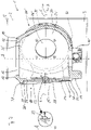
- the multi-part mold 1 in turn has an upper mold box 2, a lower mold box 3 and a core 4, which, however, is now in one piece.
- the flasks 2, 3 and the core 4 are enclosed in a casting frame 5, which is fastened all around to the dividing flange 6 along a dividing plane 7 between the upper flask 2 and the lower flask 3.
- a central rotor axis 8 is also shown. Compared to this central rotor axis 8, the cavity 10 for the rotor hub has a three-fold symmetry or rotational symmetry.
- An alternative possible embodiment includes fixing the molding boxes 2, 3 with the help of ballasting weights.
- the rotor hub can also be produced in a pit in which the molding boxes 2, 3 with ballasting be fixed to each other.
- the cavity 10 is already filled with a casting material, such as nodular graphite.
- the central rotor axis 8 is positioned vertically, with the rotor shaft connection 12 at the top and the part of the rotor hub facing away from the nacelle with the brackets 14, 14', 14'' for pitch drives is arranged at the bottom.
- a rotor blade connection 20 with a blade flange 22 and a blade connection reinforcement 24 is shown in the left area.
- the blade flange 22 is arranged in a closing plane 23 which is inclined relative to the central rotor axis 8, so that the rotor blades are oriented somewhat away from the nacelle. This angle is about 3° to 6°.
- the blade connection reinforcement 24 in the mold 1 is arranged perpendicularly in its own reinforcement plane 25 which is parallel to the central rotor axis 8 .
- This configuration results in an overthread dimension of the same thickness as the narrowest part of the blade attachment stiffener 24, approximately where the reference numerals 24 in 2 indicate.
- the inner side or inner wall of the blade flange 22 is perpendicular to the blade connection reinforcement 24 and not to the closing plane 23, which represents a simplification in terms of production technology.
- the point or attachment point at which the blade attachment stiffener 24 attaches to the inner wall of the blade flange 22 lies on an attachment line which is designated by the reference number 30 .
- This approach line 30 has a varying distance 31 from the end plane 23 in the circumferential direction of the blade flange 22, which is large in the upper area and very small in the lower area.
- the change in distance results from the differential angle between the closing plane 23 and the stiffening plane 25 or the plane that is spanned by the line of attachment 30 .
- the blade connection stiffener 24 also has a manhole 26 .
- fastenings 32, 34, 36 for add-on parts for example a spinner, ie a rotor hub cover, are shown.
- FIG. 1 An enlarged section marked “A” shows that the blade connection reinforcement 24 can have a kink 29 in the parting plane 7, which coincides with the cross-sectional plane 40, which makes threading even easier.
- the inner angle of the kink is less than 180° and can advantageously be between 175° and 179.8°, in particular around 179°.
- Section "A” also represents a cross-section through a cone-shaped blade connection stiffener in the area of the cone tip.
- the kink 29 or the cone tip is in section "A" in 2 shown issued outwards, ie away from the rotor axis 8 .
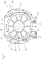
- FIG 3 shows an exemplary embodiment of a rotor hub 50 according to the invention and manufactured according to the invention.
- the structure of a ribbing 28 with a central reinforcement of the manhole 26 is shown in this side view.
- Other cast connection elements or consoles for example for sensors or the like are also shown in the area and on the blade connection reinforcement 24 without reference numbers.
- the ribbing 28 provides for a further increased stiffening with little use of material.
- the cross-sectional plane 40 runs through the centers of the rotor blade connections 20, 20', 20".
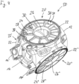
- the rotor hub 50 according to the invention 3 shown in a perspective view. Compared to the side view 3 is in the perspective view of 4
- the ribbing 28 coincides with its termination plane with the termination plane of the blade flange 22, i.e. the ribs end with the termination plane of the blade flange 22, while the blade connection stiffener 24 is arranged at a different angle.
- the ribs of the ribbing 28 are higher towards the rotor shaft and have a lower height towards the side facing away from the rotor shaft.
- the respective flat flange is stiffened up to the closing plane 23 of the respective flat flange.
- the distance 31 on the inner wall of the flat flange 22 from the attachment line 30 to the final plane 23 with the bolt holes varies according to the tilting of the two planes relative to one another.
Landscapes
- Engineering & Computer Science (AREA)
- Mechanical Engineering (AREA)
- Life Sciences & Earth Sciences (AREA)
- Sustainable Development (AREA)
- Sustainable Energy (AREA)
- Chemical & Material Sciences (AREA)
- Combustion & Propulsion (AREA)
- General Engineering & Computer Science (AREA)
- Wind Motors (AREA)
- Turbine Rotor Nozzle Sealing (AREA)
- Structures Of Non-Positive Displacement Pumps (AREA)
Applications Claiming Priority (2)
| Application Number | Priority Date | Filing Date | Title |
|---|---|---|---|
| DE102014200276.1A DE102014200276A1 (de) | 2014-01-10 | 2014-01-10 | Mehrteilige Gussform, Herstellungsverfahren, Rotornabe und Windenergieanlage |
| PCT/EP2015/050326 WO2015104370A1 (de) | 2014-01-10 | 2015-01-09 | Mehrteilige gussform, herstellungsverfahren, rotornabe und windenergieanlage |
Publications (3)
| Publication Number | Publication Date |
|---|---|
| EP3092094A1 EP3092094A1 (de) | 2016-11-16 |
| EP3092094B1 EP3092094B1 (de) | 2019-08-07 |
| EP3092094B2 true EP3092094B2 (de) | 2023-02-08 |
Family
ID=52354964
Family Applications (1)
| Application Number | Title | Priority Date | Filing Date |
|---|---|---|---|
| EP15700442.5A Active EP3092094B2 (de) | 2014-01-10 | 2015-01-09 | Mehrteilige gussform, herstellungsverfahren, rotornabe und windenergieanlage |
Country Status (5)
| Country | Link |
|---|---|
| EP (1) | EP3092094B2 (da) |
| DE (1) | DE102014200276A1 (da) |
| DK (1) | DK3092094T4 (da) |
| ES (1) | ES2756025T5 (da) |
| WO (1) | WO2015104370A1 (da) |
Families Citing this family (4)
| Publication number | Priority date | Publication date | Assignee | Title |
|---|---|---|---|---|
| DE102018108610A1 (de) | 2018-04-11 | 2019-10-17 | Wobben Properties Gmbh | Rotornabe einer Windenergieanlage, sowie Verfahren zur Montage einer solchen Rotornabe |
| CN110328333A (zh) * | 2019-07-24 | 2019-10-15 | 山东康迈信机械有限公司 | 一种侧拉模轮毂的生产方法 |
| CN111318683A (zh) * | 2020-04-21 | 2020-06-23 | 石钢京诚装备技术有限公司 | 一种大型船用锚唇的生产方法 |
| EP3945207A1 (en) * | 2020-07-30 | 2022-02-02 | Siemens Gamesa Renewable Energy Innovation & Technology S.L. | Lattice framework |
Citations (3)
| Publication number | Priority date | Publication date | Assignee | Title |
|---|---|---|---|---|
| EP1930584A2 (en) † | 2006-11-22 | 2008-06-11 | Fuji Jukogyo Kabushiki Kaisha | Hub for a horizontal axis wind turbine |
| WO2012130240A1 (en) † | 2011-03-30 | 2012-10-04 | Vestas Wind Systems A/S | A hub for a wind turbine |
| US20130280089A1 (en) † | 2012-04-19 | 2013-10-24 | General Electric Company | Hub for wind turbine rotor |
Family Cites Families (2)
| Publication number | Priority date | Publication date | Assignee | Title |
|---|---|---|---|---|
| NL1021673C1 (nl) * | 2002-10-17 | 2004-04-20 | Mecal Applied Mechanics B V | Verbeterde naaf voor een windturbine. |
| DE202004003521U1 (de) * | 2004-03-06 | 2004-06-24 | W2E Wind To Engergy Gmbh | Innenbegehbare Rotornabe |
-
2014
- 2014-01-10 DE DE102014200276.1A patent/DE102014200276A1/de not_active Withdrawn
-
2015
- 2015-01-09 EP EP15700442.5A patent/EP3092094B2/de active Active
- 2015-01-09 ES ES15700442T patent/ES2756025T5/es active Active
- 2015-01-09 WO PCT/EP2015/050326 patent/WO2015104370A1/de active Application Filing
- 2015-01-09 DK DK15700442.5T patent/DK3092094T4/da active
Patent Citations (3)
| Publication number | Priority date | Publication date | Assignee | Title |
|---|---|---|---|---|
| EP1930584A2 (en) † | 2006-11-22 | 2008-06-11 | Fuji Jukogyo Kabushiki Kaisha | Hub for a horizontal axis wind turbine |
| WO2012130240A1 (en) † | 2011-03-30 | 2012-10-04 | Vestas Wind Systems A/S | A hub for a wind turbine |
| US20130280089A1 (en) † | 2012-04-19 | 2013-10-24 | General Electric Company | Hub for wind turbine rotor |
Non-Patent Citations (5)
| Title |
|---|
| Auszug aus dem Lehrbuch "Manufacturing Engineering and Technology" by Serope Kalpakjian and Steven R. Schmid, 4"’Edition, Prentice-Hall, Inc., 2001 † |
| Declaration: Mr. Niels Skat Tiedje † |
| Film: "Metal Casting at Home Part 10" - "Another Day in my Foundry"(veröffentlicht auf YouTube 11.10.2009) † |
| Herbert Werner and Werner Sonntag: "Neue Dimensionen -Windenergie fordert die GieBereibranche", Sonderdruck aus konstruieren+giessen, Band 30, Heft 2 (2005) † |
| Screenshot von YouTube dass das Veroffentlichungsdatum von D4 zeigt † |
Also Published As
| Publication number | Publication date |
|---|---|
| EP3092094A1 (de) | 2016-11-16 |
| ES2756025T5 (es) | 2023-05-09 |
| ES2756025T3 (es) | 2020-04-24 |
| DK3092094T3 (da) | 2019-11-18 |
| WO2015104370A1 (de) | 2015-07-16 |
| DK3092094T4 (da) | 2023-05-01 |
| DE102014200276A1 (de) | 2015-07-16 |
| EP3092094B1 (de) | 2019-08-07 |
Similar Documents
| Publication | Publication Date | Title |
|---|---|---|
| EP3092094B2 (de) | Mehrteilige gussform, herstellungsverfahren, rotornabe und windenergieanlage | |
| EP2755815B1 (de) | Form und verfahren zur herstellung eines steges und steg für ein rotorblatt einer windenergieanlage | |
| DE60218217T2 (de) | Verfahren zur herstellung eines rotors eines elektromotors | |
| EP1355043B1 (de) | Laufschaufel für eine Turbomaschine | |
| DE3902151A1 (de) | Giessform zum metallgiessen und huelse hierfuer | |
| EP3018342B2 (de) | Verfahren zum herstellen eines rotorblatts einer windenergieanlage | |
| EP2396543B1 (de) | Maschinenträger zur aufnahme einer rotor-/generatorbaugruppe einer getriebelosen windenergieanlage | |
| EP0046822B1 (de) | Verfahren zum Befestigen einer Fussplatte an einem im Schleuderverfahren hergestellten Mast und Fussplatte zur Durchführung des Verfahrens | |
| EP3571411B1 (de) | Pumpenlaufrad | |
| WO1997001406A1 (de) | Speiser zur verwendung beim giessen von geschmolzenem metall | |
| EP2436458B1 (de) | Stranggießkokille | |
| EP0454098A2 (de) | Verfahren zur Herstellung von Schachtbodenstücken und Vorrichtung zur Durchführung des Verfahrens | |
| DE102019130608A1 (de) | Scheibenrad für ein Kraftfahrzeug sowie Verfahren zur Herstellung eines solchen Scheibenrades | |
| DE102018220882B4 (de) | Schleudergussvorrichtung für verschiedene Materialien | |
| EP3163075B1 (de) | Windenergieanlage, lastenverteilungssystem einer windenergieanlage und verfahren zum errichten eines turms einer windenergieanlage | |
| EP3015702B1 (de) | Rotorblatt für eine windkraftanlage und verfahren zum herstellen eines rotorblatts | |
| DE2236230A1 (de) | Form zur herstellung von masten, pfosten, saeulen oder dergleichen | |
| EP3085956B1 (de) | Turm für eine windenergieanlage sowie verfahren zum errichten einer windenergieanlage | |
| EP2472009B1 (de) | Entwässerungsvorrichtung | |
| DE10046004C2 (de) | Flugzeugtür und Formwerkzeug zur Herstellung der Flugzeugtür | |
| EP3805488B1 (de) | Modularer formensatz für giessformen zum giessen von wandsegmenten einer turmwand einer windenergieanlage | |
| EP3447279A1 (de) | Maschinenhausverkleidung für eine windenergieanlage | |
| WO2013110525A1 (de) | Ein aus guss gefertiges gehäuse für fluide | |
| DE603243C (de) | Verfahren und Vorrichtung zum Herstellen von Hohlkoerpern oder von Vollkoerpern in um die senkrechte Achse umlaufenden Schleudergussformen | |
| WO2016050264A1 (de) | Speisereinsatz für eine vertikal geteilte giessform |
Legal Events
| Date | Code | Title | Description |
|---|---|---|---|
| PUAI | Public reference made under article 153(3) epc to a published international application that has entered the european phase |
Free format text: ORIGINAL CODE: 0009012 |
|
| 17P | Request for examination filed |
Effective date: 20160623 |
|
| AK | Designated contracting states |
Kind code of ref document: A1 Designated state(s): AL AT BE BG CH CY CZ DE DK EE ES FI FR GB GR HR HU IE IS IT LI LT LU LV MC MK MT NL NO PL PT RO RS SE SI SK SM TR |
|
| AX | Request for extension of the european patent |
Extension state: BA ME |
|
| DAX | Request for extension of the european patent (deleted) | ||
| STAA | Information on the status of an ep patent application or granted ep patent |
Free format text: STATUS: EXAMINATION IS IN PROGRESS |
|
| 17Q | First examination report despatched |
Effective date: 20171110 |
|
| GRAP | Despatch of communication of intention to grant a patent |
Free format text: ORIGINAL CODE: EPIDOSNIGR1 |
|
| STAA | Information on the status of an ep patent application or granted ep patent |
Free format text: STATUS: GRANT OF PATENT IS INTENDED |
|
| INTG | Intention to grant announced |
Effective date: 20190218 |
|
| GRAS | Grant fee paid |
Free format text: ORIGINAL CODE: EPIDOSNIGR3 |
|
| GRAA | (expected) grant |
Free format text: ORIGINAL CODE: 0009210 |
|
| STAA | Information on the status of an ep patent application or granted ep patent |
Free format text: STATUS: THE PATENT HAS BEEN GRANTED |
|
| AK | Designated contracting states |
Kind code of ref document: B1 Designated state(s): AL AT BE BG CH CY CZ DE DK EE ES FI FR GB GR HR HU IE IS IT LI LT LU LV MC MK MT NL NO PL PT RO RS SE SI SK SM TR |
|
| REG | Reference to a national code |
Ref country code: GB Ref legal event code: FG4D Free format text: NOT ENGLISH |
|
| REG | Reference to a national code |
Ref country code: CH Ref legal event code: EP Ref country code: AT Ref legal event code: REF Ref document number: 1163065 Country of ref document: AT Kind code of ref document: T Effective date: 20190815 |
|
| REG | Reference to a national code |
Ref country code: DE Ref legal event code: R096 Ref document number: 502015009881 Country of ref document: DE |
|
| REG | Reference to a national code |
Ref country code: IE Ref legal event code: FG4D Free format text: LANGUAGE OF EP DOCUMENT: GERMAN |
|
| REG | Reference to a national code |
Ref country code: DK Ref legal event code: T3 Effective date: 20191111 |
|
| REG | Reference to a national code |
Ref country code: NL Ref legal event code: MP Effective date: 20190807 |
|
| REG | Reference to a national code |
Ref country code: LT Ref legal event code: MG4D |
|
| PG25 | Lapsed in a contracting state [announced via postgrant information from national office to epo] |
Ref country code: PT Free format text: LAPSE BECAUSE OF FAILURE TO SUBMIT A TRANSLATION OF THE DESCRIPTION OR TO PAY THE FEE WITHIN THE PRESCRIBED TIME-LIMIT Effective date: 20191209 Ref country code: NO Free format text: LAPSE BECAUSE OF FAILURE TO SUBMIT A TRANSLATION OF THE DESCRIPTION OR TO PAY THE FEE WITHIN THE PRESCRIBED TIME-LIMIT Effective date: 20191107 Ref country code: NL Free format text: LAPSE BECAUSE OF FAILURE TO SUBMIT A TRANSLATION OF THE DESCRIPTION OR TO PAY THE FEE WITHIN THE PRESCRIBED TIME-LIMIT Effective date: 20190807 Ref country code: BG Free format text: LAPSE BECAUSE OF FAILURE TO SUBMIT A TRANSLATION OF THE DESCRIPTION OR TO PAY THE FEE WITHIN THE PRESCRIBED TIME-LIMIT Effective date: 20191107 Ref country code: LT Free format text: LAPSE BECAUSE OF FAILURE TO SUBMIT A TRANSLATION OF THE DESCRIPTION OR TO PAY THE FEE WITHIN THE PRESCRIBED TIME-LIMIT Effective date: 20190807 Ref country code: HR Free format text: LAPSE BECAUSE OF FAILURE TO SUBMIT A TRANSLATION OF THE DESCRIPTION OR TO PAY THE FEE WITHIN THE PRESCRIBED TIME-LIMIT Effective date: 20190807 Ref country code: FI Free format text: LAPSE BECAUSE OF FAILURE TO SUBMIT A TRANSLATION OF THE DESCRIPTION OR TO PAY THE FEE WITHIN THE PRESCRIBED TIME-LIMIT Effective date: 20190807 Ref country code: SE Free format text: LAPSE BECAUSE OF FAILURE TO SUBMIT A TRANSLATION OF THE DESCRIPTION OR TO PAY THE FEE WITHIN THE PRESCRIBED TIME-LIMIT Effective date: 20190807 |
|
| PG25 | Lapsed in a contracting state [announced via postgrant information from national office to epo] |
Ref country code: AL Free format text: LAPSE BECAUSE OF FAILURE TO SUBMIT A TRANSLATION OF THE DESCRIPTION OR TO PAY THE FEE WITHIN THE PRESCRIBED TIME-LIMIT Effective date: 20190807 Ref country code: GR Free format text: LAPSE BECAUSE OF FAILURE TO SUBMIT A TRANSLATION OF THE DESCRIPTION OR TO PAY THE FEE WITHIN THE PRESCRIBED TIME-LIMIT Effective date: 20191108 Ref country code: IS Free format text: LAPSE BECAUSE OF FAILURE TO SUBMIT A TRANSLATION OF THE DESCRIPTION OR TO PAY THE FEE WITHIN THE PRESCRIBED TIME-LIMIT Effective date: 20191207 Ref country code: RS Free format text: LAPSE BECAUSE OF FAILURE TO SUBMIT A TRANSLATION OF THE DESCRIPTION OR TO PAY THE FEE WITHIN THE PRESCRIBED TIME-LIMIT Effective date: 20190807 Ref country code: LV Free format text: LAPSE BECAUSE OF FAILURE TO SUBMIT A TRANSLATION OF THE DESCRIPTION OR TO PAY THE FEE WITHIN THE PRESCRIBED TIME-LIMIT Effective date: 20190807 |
|
| PG25 | Lapsed in a contracting state [announced via postgrant information from national office to epo] |
Ref country code: TR Free format text: LAPSE BECAUSE OF FAILURE TO SUBMIT A TRANSLATION OF THE DESCRIPTION OR TO PAY THE FEE WITHIN THE PRESCRIBED TIME-LIMIT Effective date: 20190807 |
|
| REG | Reference to a national code |
Ref country code: ES Ref legal event code: FG2A Ref document number: 2756025 Country of ref document: ES Kind code of ref document: T3 Effective date: 20200424 |
|
| PG25 | Lapsed in a contracting state [announced via postgrant information from national office to epo] |
Ref country code: IT Free format text: LAPSE BECAUSE OF FAILURE TO SUBMIT A TRANSLATION OF THE DESCRIPTION OR TO PAY THE FEE WITHIN THE PRESCRIBED TIME-LIMIT Effective date: 20190807 Ref country code: RO Free format text: LAPSE BECAUSE OF FAILURE TO SUBMIT A TRANSLATION OF THE DESCRIPTION OR TO PAY THE FEE WITHIN THE PRESCRIBED TIME-LIMIT Effective date: 20190807 Ref country code: EE Free format text: LAPSE BECAUSE OF FAILURE TO SUBMIT A TRANSLATION OF THE DESCRIPTION OR TO PAY THE FEE WITHIN THE PRESCRIBED TIME-LIMIT Effective date: 20190807 Ref country code: PL Free format text: LAPSE BECAUSE OF FAILURE TO SUBMIT A TRANSLATION OF THE DESCRIPTION OR TO PAY THE FEE WITHIN THE PRESCRIBED TIME-LIMIT Effective date: 20190807 |
|
| REG | Reference to a national code |
Ref country code: DE Ref legal event code: R026 Ref document number: 502015009881 Country of ref document: DE |
|
| PLBI | Opposition filed |
Free format text: ORIGINAL CODE: 0009260 |
|
| PG25 | Lapsed in a contracting state [announced via postgrant information from national office to epo] |
Ref country code: CZ Free format text: LAPSE BECAUSE OF FAILURE TO SUBMIT A TRANSLATION OF THE DESCRIPTION OR TO PAY THE FEE WITHIN THE PRESCRIBED TIME-LIMIT Effective date: 20190807 Ref country code: SK Free format text: LAPSE BECAUSE OF FAILURE TO SUBMIT A TRANSLATION OF THE DESCRIPTION OR TO PAY THE FEE WITHIN THE PRESCRIBED TIME-LIMIT Effective date: 20190807 Ref country code: IS Free format text: LAPSE BECAUSE OF FAILURE TO SUBMIT A TRANSLATION OF THE DESCRIPTION OR TO PAY THE FEE WITHIN THE PRESCRIBED TIME-LIMIT Effective date: 20200224 Ref country code: SM Free format text: LAPSE BECAUSE OF FAILURE TO SUBMIT A TRANSLATION OF THE DESCRIPTION OR TO PAY THE FEE WITHIN THE PRESCRIBED TIME-LIMIT Effective date: 20190807 |
|
| 26 | Opposition filed |
Opponent name: VESTAS WIND SYSTEMS A/S Effective date: 20200506 |
|
| PLAX | Notice of opposition and request to file observation + time limit sent |
Free format text: ORIGINAL CODE: EPIDOSNOBS2 |
|
| PG2D | Information on lapse in contracting state deleted |
Ref country code: IS |
|
| PG25 | Lapsed in a contracting state [announced via postgrant information from national office to epo] |
Ref country code: SI Free format text: LAPSE BECAUSE OF FAILURE TO SUBMIT A TRANSLATION OF THE DESCRIPTION OR TO PAY THE FEE WITHIN THE PRESCRIBED TIME-LIMIT Effective date: 20190807 Ref country code: MC Free format text: LAPSE BECAUSE OF FAILURE TO SUBMIT A TRANSLATION OF THE DESCRIPTION OR TO PAY THE FEE WITHIN THE PRESCRIBED TIME-LIMIT Effective date: 20190807 |
|
| REG | Reference to a national code |
Ref country code: CH Ref legal event code: PL |
|
| REG | Reference to a national code |
Ref country code: BE Ref legal event code: MM Effective date: 20200131 |
|
| PG25 | Lapsed in a contracting state [announced via postgrant information from national office to epo] |
Ref country code: LU Free format text: LAPSE BECAUSE OF NON-PAYMENT OF DUE FEES Effective date: 20200109 |
|
| PLBB | Reply of patent proprietor to notice(s) of opposition received |
Free format text: ORIGINAL CODE: EPIDOSNOBS3 |
|
| PG25 | Lapsed in a contracting state [announced via postgrant information from national office to epo] |
Ref country code: CH Free format text: LAPSE BECAUSE OF NON-PAYMENT OF DUE FEES Effective date: 20200131 Ref country code: LI Free format text: LAPSE BECAUSE OF NON-PAYMENT OF DUE FEES Effective date: 20200131 Ref country code: BE Free format text: LAPSE BECAUSE OF NON-PAYMENT OF DUE FEES Effective date: 20200131 |
|
| PG25 | Lapsed in a contracting state [announced via postgrant information from national office to epo] |
Ref country code: IE Free format text: LAPSE BECAUSE OF NON-PAYMENT OF DUE FEES Effective date: 20200109 |
|
| REG | Reference to a national code |
Ref country code: AT Ref legal event code: MM01 Ref document number: 1163065 Country of ref document: AT Kind code of ref document: T Effective date: 20200109 |
|
| PG25 | Lapsed in a contracting state [announced via postgrant information from national office to epo] |
Ref country code: AT Free format text: LAPSE BECAUSE OF NON-PAYMENT OF DUE FEES Effective date: 20200109 |
|
| RAP2 | Party data changed (patent owner data changed or rights of a patent transferred) |
Owner name: SIEMENS GAMESA RENEWABLE ENERGY SERVICE GMBH |
|
| RAP4 | Party data changed (patent owner data changed or rights of a patent transferred) |
Owner name: SIEMENS GAMESA RENEWABLE ENERGY SERVICE GMBH |
|
| PG25 | Lapsed in a contracting state [announced via postgrant information from national office to epo] |
Ref country code: MT Free format text: LAPSE BECAUSE OF FAILURE TO SUBMIT A TRANSLATION OF THE DESCRIPTION OR TO PAY THE FEE WITHIN THE PRESCRIBED TIME-LIMIT Effective date: 20190807 Ref country code: CY Free format text: LAPSE BECAUSE OF FAILURE TO SUBMIT A TRANSLATION OF THE DESCRIPTION OR TO PAY THE FEE WITHIN THE PRESCRIBED TIME-LIMIT Effective date: 20190807 |
|
| REG | Reference to a national code |
Ref country code: DE Ref legal event code: R081 Ref document number: 502015009881 Country of ref document: DE Owner name: SIEMENS GAMESA RENEWABLE ENERGY SERVICE GMBH, DE Free format text: FORMER OWNER: SENVION GMBH, 22297 HAMBURG, DE |
|
| PG25 | Lapsed in a contracting state [announced via postgrant information from national office to epo] |
Ref country code: MK Free format text: LAPSE BECAUSE OF FAILURE TO SUBMIT A TRANSLATION OF THE DESCRIPTION OR TO PAY THE FEE WITHIN THE PRESCRIBED TIME-LIMIT Effective date: 20190807 |
|
| APAH | Appeal reference modified |
Free format text: ORIGINAL CODE: EPIDOSCREFNO |
|
| APBM | Appeal reference recorded |
Free format text: ORIGINAL CODE: EPIDOSNREFNO |
|
| APBP | Date of receipt of notice of appeal recorded |
Free format text: ORIGINAL CODE: EPIDOSNNOA2O |
|
| APBU | Appeal procedure closed |
Free format text: ORIGINAL CODE: EPIDOSNNOA9O |
|
| PUAH | Patent maintained in amended form |
Free format text: ORIGINAL CODE: 0009272 |
|
| STAA | Information on the status of an ep patent application or granted ep patent |
Free format text: STATUS: PATENT MAINTAINED AS AMENDED |
|
| 27A | Patent maintained in amended form |
Effective date: 20230208 |
|
| AK | Designated contracting states |
Kind code of ref document: B2 Designated state(s): AL AT BE BG CH CY CZ DE DK EE ES FI FR GB GR HR HU IE IS IT LI LT LU LV MC MK MT NL NO PL PT RO RS SE SI SK SM TR |
|
| REG | Reference to a national code |
Ref country code: DE Ref legal event code: R102 Ref document number: 502015009881 Country of ref document: DE |
|
| PGFP | Annual fee paid to national office [announced via postgrant information from national office to epo] |
Ref country code: FR Payment date: 20230123 Year of fee payment: 9 Ref country code: DK Payment date: 20230123 Year of fee payment: 9 |
|
| REG | Reference to a national code |
Ref country code: DK Ref legal event code: T4 Effective date: 20230426 |
|
| REG | Reference to a national code |
Ref country code: ES Ref legal event code: DC2A Ref document number: 2756025 Country of ref document: ES Kind code of ref document: T5 Effective date: 20230509 |
|
| P01 | Opt-out of the competence of the unified patent court (upc) registered |
Effective date: 20230530 |
|
| REG | Reference to a national code |
Ref country code: GB Ref legal event code: 732E Free format text: REGISTERED BETWEEN 20230727 AND 20230802 |
|
| PGFP | Annual fee paid to national office [announced via postgrant information from national office to epo] |
Ref country code: ES Payment date: 20240216 Year of fee payment: 10 |
|
| PGFP | Annual fee paid to national office [announced via postgrant information from national office to epo] |
Ref country code: DE Payment date: 20240119 Year of fee payment: 10 Ref country code: GB Payment date: 20240124 Year of fee payment: 10 |