EP3090900A1 - Method and vehicle illumination system for control of vehicle lights - Google Patents
Method and vehicle illumination system for control of vehicle lights Download PDFInfo
- Publication number
- EP3090900A1 EP3090900A1 EP15166757.3A EP15166757A EP3090900A1 EP 3090900 A1 EP3090900 A1 EP 3090900A1 EP 15166757 A EP15166757 A EP 15166757A EP 3090900 A1 EP3090900 A1 EP 3090900A1
- Authority
- EP
- European Patent Office
- Prior art keywords
- vehicle
- light
- objects
- unit
- detected
- Prior art date
- Legal status (The legal status is an assumption and is not a legal conclusion. Google has not performed a legal analysis and makes no representation as to the accuracy of the status listed.)
- Granted
Links
Images



Classifications
-
- B—PERFORMING OPERATIONS; TRANSPORTING
- B60—VEHICLES IN GENERAL
- B60Q—ARRANGEMENT OF SIGNALLING OR LIGHTING DEVICES, THE MOUNTING OR SUPPORTING THEREOF OR CIRCUITS THEREFOR, FOR VEHICLES IN GENERAL
- B60Q1/00—Arrangement of optical signalling or lighting devices, the mounting or supporting thereof or circuits therefor
- B60Q1/26—Arrangement of optical signalling or lighting devices, the mounting or supporting thereof or circuits therefor the devices being primarily intended to indicate the vehicle, or parts thereof, or to give signals, to other traffic
- B60Q1/32—Arrangement of optical signalling or lighting devices, the mounting or supporting thereof or circuits therefor the devices being primarily intended to indicate the vehicle, or parts thereof, or to give signals, to other traffic for indicating vehicle sides, e.g. clearance lights
- B60Q1/323—Arrangement of optical signalling or lighting devices, the mounting or supporting thereof or circuits therefor the devices being primarily intended to indicate the vehicle, or parts thereof, or to give signals, to other traffic for indicating vehicle sides, e.g. clearance lights on or for doors
-
- B—PERFORMING OPERATIONS; TRANSPORTING
- B60—VEHICLES IN GENERAL
- B60Q—ARRANGEMENT OF SIGNALLING OR LIGHTING DEVICES, THE MOUNTING OR SUPPORTING THEREOF OR CIRCUITS THEREFOR, FOR VEHICLES IN GENERAL
- B60Q1/00—Arrangement of optical signalling or lighting devices, the mounting or supporting thereof or circuits therefor
- B60Q1/02—Arrangement of optical signalling or lighting devices, the mounting or supporting thereof or circuits therefor the devices being primarily intended to illuminate the way ahead or to illuminate other areas of way or environments
- B60Q1/24—Arrangement of optical signalling or lighting devices, the mounting or supporting thereof or circuits therefor the devices being primarily intended to illuminate the way ahead or to illuminate other areas of way or environments for lighting other areas than only the way ahead
- B60Q1/247—Arrangement of optical signalling or lighting devices, the mounting or supporting thereof or circuits therefor the devices being primarily intended to illuminate the way ahead or to illuminate other areas of way or environments for lighting other areas than only the way ahead for illuminating the close surroundings of the vehicle, e.g. to facilitate entry or exit
-
- B—PERFORMING OPERATIONS; TRANSPORTING
- B60—VEHICLES IN GENERAL
- B60Q—ARRANGEMENT OF SIGNALLING OR LIGHTING DEVICES, THE MOUNTING OR SUPPORTING THEREOF OR CIRCUITS THEREFOR, FOR VEHICLES IN GENERAL
- B60Q2400/00—Special features or arrangements of exterior signal lamps for vehicles
- B60Q2400/40—Welcome lights, i.e. specific or existing exterior lamps to assist leaving or approaching the vehicle
Definitions
- the present invention relates generally to a vehicle illumination system for controlling the operation of external vehicle lights.
- welcome light In prior art it is known to illuminate the area around the vehicle when a driver is about to enter the vehicle. This type of illumination is called welcome light.
- a drawback with the known prior art is that the welcome light is faint and only used to guide the driver or passengers to or from the vehicle. In order to save energy, only the area outside the door the person or persons is about to enter or exit from is illuminated. Thus, when stepping out of the faintly illuminated area outside the door the vision is quickly deteriorating and the person cannot see if he is about to step into a puddle of water, mud or some other obstacles next to the car. Further, there might be other objects near the vehicle that need to be noticed. For example, broken glass or other obstacles, which may cause puncture or damage to the vehicle.
- An object of the present invention is to enable a control of vehicle exterior lights which make the parking, entering and exiting of a vehicle more safe and pleasant.
- a method performed by a vehicle illumination system for controlling the operation of a vehicle illumination unit, the method comprising:
- the method according to the invention ensures that objects present within a certain area surrounding the vehicle will be properly illuminated. Since the both the presence and position of objects are detected a light source can be directed to illuminate the specific object or objects near the vehicle with a specific light that clearly draw the driver's or passenger's attention to the objects. Thus, the driver or passenger can chose to avoid contact with the object when entering or exiting the vehicle.
- the method further comprises:
- the method further comprises:
- the method further comprises:
- the method further comprises:
- the method further comprises:
- the method further comprises:
- a vehicle illumination system for controlling the operation of an illumination unit, wherein said system is arranged to:
- said system is further arranged to:
- said system is further arranged to:
- said system is further arranged to:
- said system is further arranged to:
- said system is further arranged to:
- a computer program comprising computer readable code means, which when run in a connected vehicle illumination system is arranged to enable control of the operation of vehicle lights causes the connected vehicle illumination system arranged to enable control of the operation of vehicle lights to perform the method according to any of the above embodiments, for example as described in [0007]-[0013].
- a computer program product comprising a computer readable medium and a computer program according to the above embodiment, for example as described in [0020], wherein the computer program is stored on the computer readable medium.
- a vehicle comprising a vehicle information system according to any of the previous described embodiments, for instance according to [00014]-[0019].
- Fig.1 shows a perspective view of a vehicle 270 comprising an illumination system 100 for controlling the operation of an external illumination unit 170 adapted to illuminate an object O arranged in a peripheral area A tot of the vehicle.
- the presence and position of the object O is detected by a first detection unit 120A.
- the system also illuminates a first area A 1 at least partly surrounding the object O.
- the vehicle information system 100 may comprise one of e.g. the following: a IHU (Infotainment Head Unit), a TEM (Telematics Module), a CEM (Central Electronic Module) or an ECU (Electronic Control Module).
- Fig. 2 shows a vehicle 270 comprising the illumination system 100 for controlling the illumination system 170.
- the illumination unit 170 may comprise one or several vehicle light sources 170A, 170B, etc arranged to illuminate and area Atot in the surroundings of the vehicle in vicinity of the vehicle.
- the vehicle light sources may be mounted in or on the vehicle chassis.
- the light sources may be able to emit light having different light characteristics, such as different intensity, color or frequency.
- the illumination system 100 may be adapted to detect presence of object or objects of a first type O1 or a second type 02 in a peripheral area Atot and to illuminate said objects.
- the first type of objects O1 are objects which may annoy, harm or damage a driver, passenger or the vehicle 270 itself, for example broken glass, a puddle of water, a layer of ice or a pile of mud or other obstacles.
- the second type of object 02 is a person or human being about to enter the vehicle.
- the second type of object 02 may also be another person or animal present in the peripheral area Atot near the vehicle.
- a procedure or method in a vehicle illumination system 100 for controlling the operation of external vehicle lights illuminating a peripheral area of a vehicle 270 will now be described with reference to Fig. 3 .
- the method is initiated.
- the occurrence of an event is detected.
- an event might be turning the vehicle ignition key.
- an event might be that the driver arriving to, exiting or is in a close proximity to the vehicle. This may be detected by detecting the presence of a key fob or other portable electrical devices or wearables such as for example a smart phone.
- the event is the manual switching of a control switch in the vehicle 270.
- the event is activation of an application in a mobile device, for example a smart phone.
- another step S120 is initiated.
- the step S120 is to detect and collect environmental data received as a first signal from a first detection unit 120A in a vehicle data collection and communication unit 160.
- the data may for instance be received from detection unit 120A either by wire, or wirelessly, via for example CAN-bus ( Controller Area Network) WiFi/Wireless Local Area Network (WLAN), Bluetooth, Radio Frequency Identification (RFID), ZigBee not limiting to other wireless communication means suitable for short or media range wireless communication.
- the first signal indicates the presence of object or objects 01,02 in a peripheral area Atot surrounding the vehicle.
- the first detection unit 120A may be a camera system or an image acquisition system such as a parking sensor, ultra sound sensor, infrared sensor, automatic parking device or other devices.
- the detection unit 120A may be a reflection light sensor scanning the surroundings to detect areas with different reflection which might be a puddle of water, mud or an ice cover.
- the camera system or image acquisition system may enable the acquisition of an image or images of objects or obstacles in vicinity of the vehicle possible to use to determine the position of the objects within said peripheral area Atot.
- the characteristics of the objects is determined by a determination unit 160 by analyzing the signals from the detections unit 120A. In one embodiment said characteristics is basically the position of the object.
- a further step 140 the objects are determined to be of a first object type 01.
- this determination is made via for instance an image processing or recognition step in the camera system or another system, the characteristics of the objects, such for example size, shape and color, may be identified, whereby the object data may be provided and further transmitted to the vehicle illumination system 100.
- the determination may be performed by an image processing step comparing the processed images with images forming a part of a predefined road environment or belong within a group of obstacles or road irregularities having predefined characteristics, and/or other preferences. The information of which may be data saved in a database 150. If the objects are defined to be of the first type, a further step S150 is performed. Said step S150 activates an illumination unit 170 to illuminate said objects O1 with a light having first light characteristics. In one embodiment a first area A1 at least partly surrounding said object O1 is also illuminated.
- the method includes a further step S160, determining if the detected object is of a second object type O2.
- the second object type is a person or human being detected to be present or enter in the area Atot surrounding the vehicle.
- a further step S170 is activated.
- an activation signal is communicated to the vehicle illumination unit 170 with the order to illuminate said objects O2 with a light having second light characteristics.
- a second area A2 at least partly surrounding said object O2 is also illuminated.
- the second area A2 is in one embodiment larger that the first area A1.
- Said second light characteristics may be the same or different from the first light characteristics of step S150.
- a light having a first light characteristics is a light with for example a different color, a higher intensity or is emitted with a different frequency than a light having the second light characteristics. This in order to further mark the position of objects of the first type O1 near the vehicle which may annoy, harm or damage a driver, passenger or the vehicle 270 itself.
- a light with a second light characteristics is in one embodiment a light with a comparably low intensity adapted to illuminate the ground within an area, in vicinity of the vehicle, surrounding the detected person. The second light may be considered to be only a lead light for a person entering or exiting the vehicle. It shall be noted that both object type O1 and O2 may in one embodiment be illuminated simultaneously.
- a communication device 180 to visualize presence of object O, O1, O2 on a screen if an object or objects O, O1, O2 are detected.
- Said communication device may be a CSD centre stack display, a mobile device such as a phone or computer or similar device.
- a driver, passenger or other person may be alerted that an object of a specific type is detected in the surroundings of the vehicle.
- the position of the object or objects are visualized on the screen and in a further object an image of the object is visible.
- the image may be a real time photo of the object or a stylized image showing a graphical image of the object type.
- steps S200 and S300 is used to collect further input data from a second and third detection unit 120B, 120C.
- Said data is determined to be of a specific type or within a specific interval in steps S210, S220 and S310, 320.
- S330 the light characteristics of the light emitted from the illumination unit illuminating object is adjusted or activated.
- data about ambient light is received as a signal from a second detection unit 120B.
- the second signal indicates the intensity of the ambient light and said second detection unit 120B may be a luminosity or light sensor or a camera unit. If the detected ambient light intensity is determined to be below a certain predefined value, the intensity or light characteristics of the light is adjusted in order to further mark the position of objects of the first type O1 near the vehicle which may annoy, harm or damage a driver, passenger or the vehicle 270 itself.
- the data is received as a third signal from a third detection unit 120C.
- the third signal indicating the presence and position of an object of second type O2, i.e. a person or persons present in the vehicle and about to exit said vehicle.
- Said third detection unit 120C may be a key fob or other electrical portable devices, door lock or door handle sensor indicating that door is opened, or a pressure detection device arranged in at least one of the vehicle seats, an infrared device or a seatbelt sensor device.
- an activation signal is communicated to the vehicle illumination unit 170 to illuminate a portion of the peripheral area A tot surrounding the vehicle in the vicinity of the position of the detected person or persons with a light having a second light characteristics.
- Said portion is in one embodiment the second area A2. I.e. the area in which the person in the vehicle is about to exit to is illuminated with for example a lead light or similar light with a lower intensity or other light characteristics than the light illuminating an object of the first type O1.
- Fig. 5 discloses an illumination system 100 for controlling the operation of an external vehicle illumination unit 170.
- the system 100 is arranged to receive data, via a vehicle data collection and communication unit 130, about the presence and characteristics of objects O1, O2 detected in an area A tot surrounding the vehicle, by a first detection unit 120A.
- the system may further arranged to receive data, via the collection and communication unit 130, about surrounding ambient lights detected by a second detection unit 120B.
- the system may further be arranged to receive data about the presence of an object of a second type O2, i.e. a person, present in the vehicle by a third detection unit 120C.
- the first detection unit 120A detecting the presence and position of an objects O1, O2 is a camera, infrared or ultra sound scanner or other optical device creating a fictive image of the surroundings possible to analyze.
- the detection unit 120A may be a reflection light sensor scanning the surroundings to detect areas with different reflection which might be a puddle of water, mud or an ice cover.
- the second detection unit 120B detecting the ambient light is a luminosity or light sensor.
- the third detection unit 120C may be a key fob, door lock or door handle sensor indicating that door is opened, or a pressure detection device arranged in at least one of the vehicle seats, an infrared device or a seatbelt sensor device.
- the database 150 may be arranged for storage of sensor data and/or data of objects determined to be of a first or second type. Objects of the first type O1 may be defined to be dangerous or unpleasant for the driver, for example broken glass, a puddle of water or a pile of mud and the data saved may be information of predetermined size, shape, color or refection.
- the database may also be arranged to store vehicle data, historical data, statistical data, configuration data, pre configuration data, or other type of data.
- the database 150 may be based on a flash type of memory, disk drive of memory, virtual memory provided by a network access, not limiting to other types of storages.
- a determination unit 160 is arranged to determine if said stationary objects are dangerous or unpleasant for the driver or vehicle, by analyzing said data detected by the detection units 120A, 120B, 120C, separate or together.
- the determination unit 160 may be arranged to determine which objects that need to be illuminated and to request, via the collection and communication unit 130, the activation of an illumination unit 170 adapted to illuminate the objects detected within said scanned area A tot .
- the illumination unit is one or more light sources arranged to light up the area surrounding the vehicle. Each light source may be adapted to emit light with different intensity/brightness/color in order to differently illuminate objects depending on for example detected outside light, for example no illumination when full daylight or only extra strong illumination of objects when full daylight.
- the emitted light characteristics may depend on if the object detected is of a first or second type or possible also if it is an object determined to be of a specific importance, which for example may seriously hurt the driver or damage the vehicle. It is also possible to specially illuminate objects that self may be hurt by the vehicle, for example a child or an animal.
- Fig. 6 shows an illustration of embodiments of a vehicle illumination system 100.
- the vehicle illumination system 100 may be implemented, by means of program modules of a respective computer program comprising code means which, when run by a processing unit 250 causes the vehicle illumination system 100 to perform the above-described actions.
- the processing unit 250 may comprise a single Central Processing Unit (CPU), or could comprise two or more processing units.
- the processing unit 250 may include general purpose microprocessors, instruction set processors and/or related chips sets and/or special purpose microprocessors such as Application Specific Integrated Circuits (ASICs).
- ASICs Application Specific Integrated Circuits
- the processing unit 250 may also comprise a storage for caching purposes.
- Each computer program may be carried by a computer program product 260 in the vehicle illumination system 100, shown in Fig. 1, 2 , 3 , 4 and 5 in the form of a memory having a computer readable medium and being connected to the processing unit 250.
- the computer program product 260 or memory thus comprises a computer readable medium on which the computer program is stored e.g. in the form of computer program modules "m".
- the memory 260 may be a flash memory, a Random-Access Memory (RAM), a Read-Only Memory (ROM) or an Electrically Erasable Programmable ROM (EEPROM), and the program modules m could in alternative embodiments be distributed on different computer program products in the form of memories within the vehicle illumination system 100.
- the vehicle illumination system 100 may further comprise a communication interface 265.
- the communication interface 265 may also be arranged to communicate with for example a vehicle specific parking detection system, a vehicle to vehicle communication network or vehicle internal or external communication devices such as an information screen, mobile communication device, computer or computer network.
- the communication interface 265 may comprise chip set adopted for communication via CAN bus (Controller Area Network) or communication adopted to ISO 11898.
- Other examples of standards which may be supported by the communication interface 265 are: ZigBee, Bluetooth, RFID (Radio frequency identification), USB (Universal serial bus), or IEEE 802.11 (Institute of Electrical and Electronics Engineers), including but not limited to 802.11 a/b/n or other similar forthcoming standards.
- the communication interface 265 may comprise an antenna.
Landscapes
- Engineering & Computer Science (AREA)
- Mechanical Engineering (AREA)
- Lighting Device Outwards From Vehicle And Optical Signal (AREA)
Abstract
Description
- The present invention relates generally to a vehicle illumination system for controlling the operation of external vehicle lights.
- In prior art it is known to illuminate the area around the vehicle when a driver is about to enter the vehicle. This type of illumination is called welcome light.
- See for example
DE102012020414A1 which presents a method or a device carrying out detection of a person in the surrounding of a motor vehicle, and determining detection areas based on actual person position. Illumination devices corresponding to the respective detection area is activated, when a person is detected in the detection area and when a signal from a vehicle key or similar is detected. - It is also known systems for controlling the operation of automobile lamps where a parking environment and obstacles existing near the automobile is recognized and automotive lamps are turned on on the basis of such a recognition, see for example
EP2711244A2 . However, here lamps are turned on in those areas free from obstacles in order to enlighten only the area from which the driver most probably will appear. - A drawback with the known prior art is that the welcome light is faint and only used to guide the driver or passengers to or from the vehicle. In order to save energy, only the area outside the door the person or persons is about to enter or exit from is illuminated. Thus, when stepping out of the faintly illuminated area outside the door the vision is quickly deteriorating and the person cannot see if he is about to step into a puddle of water, mud or some other obstacles next to the car. Further, there might be other objects near the vehicle that need to be noticed. For example, broken glass or other obstacles, which may cause puncture or damage to the vehicle.
- An object of the present invention is to enable a control of vehicle exterior lights which make the parking, entering and exiting of a vehicle more safe and pleasant.
- According to one embodiment a method is provided performed by a vehicle illumination system for controlling the operation of a vehicle illumination unit, the method comprising:
- Receiving an initiating signal declaring occurrence of an event
- Receiving a first signal from a first detection unit indicating the presence and position of objects in a peripheral area surrounding the vehicle, up on the occurrence of an event
- Communicating an activation signal to the vehicle illumination unit to illuminate said objects with a light having first light characteristics if an object is detected.
- The method according to the invention ensures that objects present within a certain area surrounding the vehicle will be properly illuminated. Since the both the presence and position of objects are detected a light source can be directed to illuminate the specific object or objects near the vehicle with a specific light that clearly draw the driver's or passenger's attention to the objects. Thus, the driver or passenger can chose to avoid contact with the object when entering or exiting the vehicle.
- According to another embodiment, the method further comprises:
- Determining object characteristics.
- According to another embodiment, the method further comprises:
- Determining if said objects is of a first object type forming a part of a predefined road environment or belong within a group of obstacles or road irregularities having predefined characteristics.
- According to another embodiment, the method further comprises:
- Determining if said objects is of a second object type defined as a person,
- Communicating an activation signal to the vehicle illumination unit to illuminate said objects with a light having second light characteristics if the object detected is of the second object type.
- According to another embodiment, the method further comprises:
- Receiving a second signal from a second detection unit indicating the intensity of the ambient light
- Determining if the intensity of the ambient light is below a predefined value
- Communicating an activation signal to the vehicle illumination unit to illuminate the detected objects with a light having third light characteristic if said intensity of the ambient light is below the predefined value.
- According to another embodiment, the method further comprises:
- Receiving a signal from a third detection unit indicating the presence and position of person or persons present in the vehicle and about to exit said vehicle
- Communicating an activation signal to the vehicle illumination unit to illuminate the peripheral area surrounding the vehicle in the vicinity of the position of the detected person or persons with a light having a second light characteristics if a person is about to exit said vehicle.
- According to another embodiment, the method further comprises:
- Communicating an activation signal to a communication device to visualize presence of object on a screen if object is detected.
- According to another embodiment, a vehicle illumination system is provided for controlling the operation of an illumination unit, wherein said system is arranged to:
- Receive, in a vehicle data collection and communication unit, an initiating signal from a system initiating unit, declaring occurrence of an event
- Receive, in a vehicle data collection and communication unit, a first signal from a first detection unit indicating the presence and position of objects in a peripheral area surrounding the vehicle, up on the occurrence of an event
- Communicate, by the vehicle data collection and communication unit, an activation signal to the vehicle illumination unit, to illuminate said objects with a light having first light characteristics if an object is detected.
- According to another embodiment, said system is further arranged to:
- Determine by a determination unit the object characteristics.
- According to another embodiment, said system is further arranged to:
- Determine by a determination unit if said object is of a first object type forming a part of a predefined road environment or belong within a group of obstacles or road irregularities having predefined characteristics.
- According to another embodiment, said system is further arranged to:
- Determine by a determination unit if said object is of a second object type defined as a person,
- Communicate, by the vehicle data collection and communication unit, an activation signal to the vehicle illumination unit to illuminate said objects with a light having second light characteristics if the object detected is of the second object type.
- According to another embodiment, said system is further arranged to:
- Receive, in a vehicle data collection and communication unit, a second signal from a second detection unit indicating the intensity of the ambient light
- Determine, by the determination unit, if the intensity of the ambient light is below a predefined value
- Communicate, by the vehicle data collection and communication unit, an activation signal to the vehicle illumination unit to illuminate the detected objects with a light having third light characteristic if said intensity of the ambient light is below the predefined value.
- According to another embodiment, said system is further arranged to:
- Communicate, by a vehicle data collection and communication unit, an activation signal to a communication device to visualise presence of object on a screen if object is detected.
- According to another embodiment, a computer program is provided, comprising computer readable code means, which when run in a connected vehicle illumination system is arranged to enable control of the operation of vehicle lights causes the connected vehicle illumination system arranged to enable control of the operation of vehicle lights to perform the method according to any of the above embodiments, for example as described in [0007]-[0013].
- According to another embodiment a computer program product is provided, comprising a computer readable medium and a computer program according to the above embodiment, for example as described in [0020], wherein the computer program is stored on the computer readable medium.
- According to another embodiment a vehicle is provided comprising a vehicle information system according to any of the previous described embodiments, for instance according to [00014]-[0019].
- Additional technical features and corresponding advantages of the above mentioned method, system, computer program and computer program product will be discussed in further detail in the following.
- The invention is now described, by way of example, with reference to the accompanying drawings, in which:
-
Fig. 1 shows a perspective view of a vehicle comprising an illumination system according to the invention. -
Fig. 2 is a vehicle comprising an illumination system according to the invention. -
Fig. 3 is a flow chart illustrating a procedure in a vehicle illumination system. -
Fig. 4 are additional flow charts illustrating embodiments of the procedure in the vehicle illumination system. -
Fig. 5 illustrates example embodiments of a vehicle illumination system. -
Fig. 6 shows a further example of a vehicle illumination system. - In the following, a detailed description of the invention will be given. In the drawing figures, like reference numerals designate identical or corresponding elements throughout the several figures. It will be appreciated that these figures are for illustration only and are not in any way restricting the scope of the invention.
-
Fig.1 shows a perspective view of avehicle 270 comprising anillumination system 100 for controlling the operation of anexternal illumination unit 170 adapted to illuminate an object O arranged in a peripheral area Atot of the vehicle. The presence and position of the object O is detected by afirst detection unit 120A. In one embodiment the system also illuminates a first area A1 at least partly surrounding the object O. Thevehicle information system 100 may comprise one of e.g. the following: a IHU (Infotainment Head Unit), a TEM (Telematics Module), a CEM (Central Electronic Module) or an ECU (Electronic Control Module). -
Fig. 2 shows avehicle 270 comprising theillumination system 100 for controlling theillumination system 170. Theillumination unit 170 may comprise one or severalvehicle light sources illumination system 100 may be adapted to detect presence of object or objects of a first type O1 or asecond type 02 in a peripheral area Atot and to illuminate said objects. The first type of objects O1 are objects which may annoy, harm or damage a driver, passenger or thevehicle 270 itself, for example broken glass, a puddle of water, a layer of ice or a pile of mud or other obstacles. The second type ofobject 02, is a person or human being about to enter the vehicle. The second type ofobject 02 may also be another person or animal present in the peripheral area Atot near the vehicle. - A procedure or method in a
vehicle illumination system 100 for controlling the operation of external vehicle lights illuminating a peripheral area of avehicle 270 will now be described with reference toFig. 3 . In a first step S100, the method is initiated. In other step S110 the occurrence of an event is detected. According to one embodiment, an event might be turning the vehicle ignition key. According to another embodiment, an event might be that the driver arriving to, exiting or is in a close proximity to the vehicle. This may be detected by detecting the presence of a key fob or other portable electrical devices or wearables such as for example a smart phone. According to one embodiment, the event is the manual switching of a control switch in thevehicle 270. According to one embodiment, the event is activation of an application in a mobile device, for example a smart phone. If an event has occurred, another step S120 is initiated. The step S120 is to detect and collect environmental data received as a first signal from afirst detection unit 120A in a vehicle data collection andcommunication unit 160. The data may for instance be received fromdetection unit 120A either by wire, or wirelessly, via for example CAN-bus ( Controller Area Network) WiFi/Wireless Local Area Network (WLAN), Bluetooth, Radio Frequency Identification (RFID), ZigBee not limiting to other wireless communication means suitable for short or media range wireless communication. The first signal indicates the presence of object or objects 01,02 in a peripheral area Atot surrounding the vehicle. Thefirst detection unit 120A may be a camera system or an image acquisition system such as a parking sensor, ultra sound sensor, infrared sensor, automatic parking device or other devices. In another embodiment thedetection unit 120A may be a reflection light sensor scanning the surroundings to detect areas with different reflection which might be a puddle of water, mud or an ice cover. The camera system or image acquisition system may enable the acquisition of an image or images of objects or obstacles in vicinity of the vehicle possible to use to determine the position of the objects within said peripheral area Atot. In a further step S130 the characteristics of the objects is determined by adetermination unit 160 by analyzing the signals from thedetections unit 120A. In one embodiment said characteristics is basically the position of the object. In a further step 140 the objects are determined to be of afirst object type 01. In one embodiment this determination is made via for instance an image processing or recognition step in the camera system or another system, the characteristics of the objects, such for example size, shape and color, may be identified, whereby the object data may be provided and further transmitted to thevehicle illumination system 100. According to one embodiment, the determination may be performed by an image processing step comparing the processed images with images forming a part of a predefined road environment or belong within a group of obstacles or road irregularities having predefined characteristics, and/or other preferences. The information of which may be data saved in adatabase 150. If the objects are defined to be of the first type, a further step S150 is performed. Said step S150 activates anillumination unit 170 to illuminate said objects O1 with a light having first light characteristics. In one embodiment a first area A1 at least partly surrounding said object O1 is also illuminated. - In one embodiment the method includes a further step S160, determining if the detected object is of a second object type O2. The second object type is a person or human being detected to be present or enter in the area Atot surrounding the vehicle. When a second object type O2 is detected a further step S170 is activated. In
step 170 an activation signal is communicated to thevehicle illumination unit 170 with the order to illuminate said objects O2 with a light having second light characteristics. In one embodiment a second area A2 at least partly surrounding said object O2 is also illuminated. The second area A2 is in one embodiment larger that the first area A1. - Said second light characteristics may be the same or different from the first light characteristics of step S150. In one embodiment a light having a first light characteristics is a light with for example a different color, a higher intensity or is emitted with a different frequency than a light having the second light characteristics. This in order to further mark the position of objects of the first type O1 near the vehicle which may annoy, harm or damage a driver, passenger or the
vehicle 270 itself. A light with a second light characteristics is in one embodiment a light with a comparably low intensity adapted to illuminate the ground within an area, in vicinity of the vehicle, surrounding the detected person. The second light may be considered to be only a lead light for a person entering or exiting the vehicle. It shall be noted that both object type O1 and O2 may in one embodiment be illuminated simultaneously. - In a further step S180 the system is used to communicate, by the collection and
communication unit 130, an activation signal to acommunication device 180 to visualize presence of object O, O1, O2 on a screen if an object or objects O, O1, O2 are detected. Said communication device may be a CSD centre stack display, a mobile device such as a phone or computer or similar device. On said screen a driver, passenger or other person may be alerted that an object of a specific type is detected in the surroundings of the vehicle. In one embodiment the position of the object or objects are visualized on the screen and in a further object an image of the object is visible. The image may be a real time photo of the object or a stylized image showing a graphical image of the object type. - A further procedure or method in a
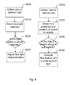
vehicle illumination system 100 for controlling the operation of external vehicle lights illuminating a peripheral area of avehicle 270 will now be described with reference toFig. 4 . This is a method where steps S200 and S300 is used to collect further input data from a second andthird detection unit 120B, 120C. Said data is determined to be of a specific type or within a specific interval in steps S210, S220 and S310, 320. In a final step S230, S330 the light characteristics of the light emitted from the illumination unit illuminating object is adjusted or activated. In one embodiment data about ambient light is received as a signal from asecond detection unit 120B. The second signal indicates the intensity of the ambient light and saidsecond detection unit 120B may be a luminosity or light sensor or a camera unit. If the detected ambient light intensity is determined to be below a certain predefined value, the intensity or light characteristics of the light is adjusted in order to further mark the position of objects of the first type O1 near the vehicle which may annoy, harm or damage a driver, passenger or thevehicle 270 itself. In one embodiment the data is received as a third signal from athird detection unit 120C. The third signal indicating the presence and position of an object of second type O2, i.e. a person or persons present in the vehicle and about to exit said vehicle. Saidthird detection unit 120C may be a key fob or other electrical portable devices, door lock or door handle sensor indicating that door is opened, or a pressure detection device arranged in at least one of the vehicle seats, an infrared device or a seatbelt sensor device. When an object of the second type O2 is detected to exit the vehicle, an activation signal is communicated to thevehicle illumination unit 170 to illuminate a portion of the peripheral area Atot surrounding the vehicle in the vicinity of the position of the detected person or persons with a light having a second light characteristics. Said portion is in one embodiment the second area A2. I.e. the area in which the person in the vehicle is about to exit to is illuminated with for example a lead light or similar light with a lower intensity or other light characteristics than the light illuminating an object of the first type O1. -
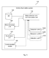
Fig. 5 discloses anillumination system 100 for controlling the operation of an externalvehicle illumination unit 170. Thesystem 100 is arranged to receive data, via a vehicle data collection andcommunication unit 130, about the presence and characteristics of objects O1, O2 detected in an area Atot surrounding the vehicle, by afirst detection unit 120A. The system may further arranged to receive data, via the collection andcommunication unit 130, about surrounding ambient lights detected by asecond detection unit 120B. The system may further be arranged to receive data about the presence of an object of a second type O2, i.e. a person, present in the vehicle by athird detection unit 120C. In one embodiment thefirst detection unit 120A detecting the presence and position of an objects O1, O2 is a camera, infrared or ultra sound scanner or other optical device creating a fictive image of the surroundings possible to analyze. In another embodiment thedetection unit 120A may be a reflection light sensor scanning the surroundings to detect areas with different reflection which might be a puddle of water, mud or an ice cover. In one embodiment thesecond detection unit 120B detecting the ambient light is a luminosity or light sensor. In another embodiment thethird detection unit 120C may be a key fob, door lock or door handle sensor indicating that door is opened, or a pressure detection device arranged in at least one of the vehicle seats, an infrared device or a seatbelt sensor device. Thedatabase 150 may be arranged for storage of sensor data and/or data of objects determined to be of a first or second type. Objects of the first type O1 may be defined to be dangerous or unpleasant for the driver, for example broken glass, a puddle of water or a pile of mud and the data saved may be information of predetermined size, shape, color or refection. The database may also be arranged to store vehicle data, historical data, statistical data, configuration data, pre configuration data, or other type of data. Thedatabase 150 may be based on a flash type of memory, disk drive of memory, virtual memory provided by a network access, not limiting to other types of storages. Adetermination unit 160 is arranged to determine if said stationary objects are dangerous or unpleasant for the driver or vehicle, by analyzing said data detected by thedetection units determination unit 160 may be arranged to determine which objects that need to be illuminated and to request, via the collection andcommunication unit 130, the activation of anillumination unit 170 adapted to illuminate the objects detected within said scanned area Atot. In an embodiment the illumination unit is one or more light sources arranged to light up the area surrounding the vehicle. Each light source may be adapted to emit light with different intensity/brightness/color in order to differently illuminate objects depending on for example detected outside light, for example no illumination when full daylight or only extra strong illumination of objects when full daylight. In one embodiment it is also possible to vary the characteristics or the emitted light depending on objects detected. I.e. the emitted light characteristics may depend on if the object detected is of a first or second type or possible also if it is an object determined to be of a specific importance, which for example may seriously hurt the driver or damage the vehicle. It is also possible to specially illuminate objects that self may be hurt by the vehicle, for example a child or an animal. -
Fig. 6 shows an illustration of embodiments of avehicle illumination system 100. Thevehicle illumination system 100 may be implemented, by means of program modules of a respective computer program comprising code means which, when run by aprocessing unit 250 causes thevehicle illumination system 100 to perform the above-described actions. Theprocessing unit 250 may comprise a single Central Processing Unit (CPU), or could comprise two or more processing units. For example, theprocessing unit 250 may include general purpose microprocessors, instruction set processors and/or related chips sets and/or special purpose microprocessors such as Application Specific Integrated Circuits (ASICs). Theprocessing unit 250 may also comprise a storage for caching purposes. - Each computer program may be carried by a
computer program product 260 in thevehicle illumination system 100, shown inFig. 1, 2 ,3 ,4 and5 in the form of a memory having a computer readable medium and being connected to theprocessing unit 250. Thecomputer program product 260 or memory thus comprises a computer readable medium on which the computer program is stored e.g. in the form of computer program modules "m". For example, thememory 260 may be a flash memory, a Random-Access Memory (RAM), a Read-Only Memory (ROM) or an Electrically Erasable Programmable ROM (EEPROM), and the program modules m could in alternative embodiments be distributed on different computer program products in the form of memories within thevehicle illumination system 100. - The
vehicle illumination system 100 may further comprise acommunication interface 265. Thecommunication interface 265 may also be arranged to communicate with for example a vehicle specific parking detection system, a vehicle to vehicle communication network or vehicle internal or external communication devices such as an information screen, mobile communication device, computer or computer network. In an embodiment thecommunication interface 265 may comprise chip set adopted for communication via CAN bus (Controller Area Network) or communication adopted to ISO 11898. Other examples of standards which may be supported by the communication interface 265are: ZigBee, Bluetooth, RFID (Radio frequency identification), USB (Universal serial bus), or IEEE 802.11 (Institute of Electrical and Electronics Engineers), including but not limited to 802.11 a/b/n or other similar forthcoming standards. Thecommunication interface 265 may comprise an antenna. Thecommunication interface 265 may be connectable to an external antenna. Theillumination system 100 may further comprise one ormore storage units 266 andfurther functionality 267 useful for thevehicle information system 100 to serve its purpose as a vehicle illumination system, such as power supply, internal communications bus, internal cooling, database engine, operating system, not limiting to other functionalities. - A preferred embodiment of vehicle illumination system according to the invention has been described. However, the person skilled in the art realizes that this can be varied within the scope of the appended claims without departing from the inventive idea.
- All the described alternative embodiments above or parts of an embodiment can be freely combined without departing from the inventive idea as long as the combination is not contradictory.
Claims (15)
- Method performed by a vehicle illumination system (100) for controlling the operation of a vehicle illumination unit (170), said method comprising:- Receiving an initiating signal declaring occurrence of an event- Receiving a first signal from a first detection unit (120A) indicating the presence and position of object or objects (O) in a peripheral area (Atot) surrounding the vehicle, up on the occurrence of an event- Communicating an activation signal to the vehicle illumination unit (170) to illuminate said objects (O) with a light having first light characteristics if an object (O) is detected.
- The method according to claim 1, further comprising:- Determining object characteristics.
- The method according to claim 1 or 2, further comprising:- Determining if said objects (O) is of a first object type (O1) forming a part of a predefined road environment or belong within a group of obstacles or road irregularities having predefined characteristics.
- The method according to claim 3, further comprising:- Determining if said objects (O) is of a second object type (O2) defined as a person,- Communicating an activation signal to the vehicle illumination unit (170) to illuminate said objects (O) with a light having second light characteristics if the object (O) detected is of the second object type (O2).
- The method according to any of the above claims, further comprising:- Receiving a second signal from a second detection unit (120B) indicating the intensity of the ambient light- Determining if the intensity of the ambient light is below a predefined value- Communicating an activation signal to the vehicle illumination unit (170) to illuminate the detected objects (O, O1, O2) with a light having third light characteristic if said intensity of the ambient light is below the predefined value.
- The method according to any of the above claims, further comprising:- Receiving a signal from a third detection unit (120C) indicating the presence and position of an object (O) in the vehicle,- Determining if said object is of a second object type (02) defined as a person and if said person or persons is about to exit said vehicle- Communicating an activation signal to the vehicle illumination unit (170) to illuminate a peripheral area (A1) surrounding the vehicle in the vicinity of the position of the detected person or persons with a light having a second light characteristics if a person is about to exit said vehicle.
- The method according to any of the above claims, further comprising:- Communicating an activation signal to a communication device (180) to visualise presence of object (O) on a screen if object (O) is detected.
- A vehicle illumination system (100) for controlling the operation of a illumination unit (170), characterized in that said system is arranged to- Receive, in a vehicle data collection and communication unit (130), an initiating signal declaring occurrence of an event- Receive, in a vehicle data collection and communication unit (130), a first signal from a first detection unit (120A) indicating the presence and position of object or objects (O) in a peripheral area (Atot) surrounding the vehicle, up on the occurrence of an event- Communicate, by the collection and communication unit (130), an activation signal to the vehicle illumination unit (170), to illuminate said objects (O) with a light having first light characteristics if an object (O) is detected.
- The vehicle illumination system (100) according to claim 8, further being arranged to:- Determine by a determination unit (160) the object characteristics.
- The vehicle illumination system (100) according to claim 8 or 9, further being arranged to- Determine by a determination unit (160) if said objects (O) is of a first object type (O1) forming a part of a predefined road environment or belong within a group of obstacles or road irregularities having predefined characteristics.
- The vehicle illumination system (100) according claim 9 or 10, further being arranged to- Determine by a determination unit (160) if said objects (O) is of a second object type (02) defined as a person,- Communicate, by the collection and communication unit (130), an activation signal to the vehicle illumination unit (170) to illuminate said objects (O) with a light having second light characteristics if the object (O) detected is of the second object type (O2).
- The vehicle communication system according to any of claims 8-11, further being arranged to- Communicate, by the collection and communication unit (130), an activation signal to a communication device (180) to visualise presence of object (O, O1, O2) on a screen if object (O, O1, O2) is detected.
- A computer program, comprising computer readable code means, which when run in a connected vehicle illumination system (100) arranged to enable control of the operation of vehicle lights causes the connected vehicle illumination system (100) arranged to enable control of the operation of vehicle lights to perform the method according to any of the claims 1-7.
- A computer program product, comprising a computer readable medium and a computer program according to claim 13, wherein the computer program is stored on the computer readable medium.
- Vehicle (270) comprising a vehicle illumination system (100) according to any of the previous claims 8-12.
Priority Applications (1)
| Application Number | Priority Date | Filing Date | Title |
|---|---|---|---|
| EP15166757.3A EP3090900B1 (en) | 2015-05-07 | 2015-05-07 | Method and vehicle illumination system for control of vehicle lights |
Applications Claiming Priority (1)
| Application Number | Priority Date | Filing Date | Title |
|---|---|---|---|
| EP15166757.3A EP3090900B1 (en) | 2015-05-07 | 2015-05-07 | Method and vehicle illumination system for control of vehicle lights |
Publications (2)
| Publication Number | Publication Date |
|---|---|
| EP3090900A1 true EP3090900A1 (en) | 2016-11-09 |
| EP3090900B1 EP3090900B1 (en) | 2021-09-29 |
Family
ID=53054938
Family Applications (1)
| Application Number | Title | Priority Date | Filing Date |
|---|---|---|---|
| EP15166757.3A Active EP3090900B1 (en) | 2015-05-07 | 2015-05-07 | Method and vehicle illumination system for control of vehicle lights |
Country Status (1)
| Country | Link |
|---|---|
| EP (1) | EP3090900B1 (en) |
Cited By (13)
| Publication number | Priority date | Publication date | Assignee | Title |
|---|---|---|---|---|
| CN109017811A (en) * | 2017-06-12 | 2018-12-18 | 通用汽车环球科技运作有限责任公司 | For providing passenger's system and method used the enhancing of autonomous vehicle |
| US10556584B2 (en) | 2018-01-09 | 2020-02-11 | Ford Global Technologies, Llc | Vehicle vision |
| US10586448B2 (en) | 2018-06-05 | 2020-03-10 | Ford Global Technologies, Llc | Hazard mitigation for access to passenger vehicles |
| WO2020234063A1 (en) * | 2019-05-21 | 2020-11-26 | Bayerische Motoren Werke Aktiengesellschaft | Lighting device for a motor vehicle |
| CN112193151A (en) * | 2020-09-07 | 2021-01-08 | 江苏大学 | A lift-type welcome car lamp control system and control method |
| US11254258B2 (en) * | 2015-10-27 | 2022-02-22 | Koito Manufacturing Co., Ltd. | Vehicle component, and vehicle |
| WO2022073733A1 (en) * | 2020-10-07 | 2022-04-14 | Audi Ag | Motor vehicle and method for operating an illumination device of a motor vehicle |
| DE102021000247A1 (en) | 2021-01-19 | 2022-07-21 | Mercedes-Benz Group AG | Method for operating an area lighting device of a vehicle |
| WO2023012047A1 (en) * | 2021-08-06 | 2023-02-09 | Bayerische Motoren Werke Aktiengesellschaft | Motor vehicle having a projection unit, and method for operating a motor vehicle |
| US11590891B2 (en) | 2020-01-16 | 2023-02-28 | Caterpillar Paving Products Inc. | Control system for a machine |
| JP2024022223A (en) * | 2022-08-05 | 2024-02-16 | ミネベアミツミ株式会社 | Vehicle lighting system |
| GB2628088A (en) * | 2023-03-09 | 2024-09-18 | Jaguar Land Rover Ltd | Vehicle lighting system control |
| GB2635717A (en) * | 2023-11-22 | 2025-05-28 | Jaguar Land Rover Ltd | Courtesy light control |
Citations (6)
| Publication number | Priority date | Publication date | Assignee | Title |
|---|---|---|---|---|
| FR2929193A1 (en) * | 2008-03-27 | 2009-10-02 | Peugeot Citroen Automobiles Sa | Variable illumination realizing device for motor vehicle, has position sensors sensitive to presence of user in area covered by sensor sensitivity field to control lighting and/or extinction of light sources and to optimally illuminate area |
| DE102008063564A1 (en) * | 2008-12-18 | 2010-06-24 | Daimler Ag | Device for detecting condition concerning to presence of water/ice in lane surface of motor vehicle, has light producing unit and/or receiver arranged in side mirror and/or handle so that lane surface conditions are detected in exit region |
| EP2711244A2 (en) | 2011-05-19 | 2014-03-26 | Continental Automotive GmbH | System and method for controlling the operation of automotive lamps |
| DE102012020414A1 (en) | 2012-10-18 | 2014-04-24 | Volkswagen Aktiengesellschaft | Method for activating illumination device e.g. left headlight, for illuminating surrounding of passenger car, involves activating one of illumination devices, where illumination areas of devices are attached to respective detection areas |
| DE102013001086A1 (en) * | 2013-01-23 | 2014-07-24 | Audi Ag | A motor vehicle comprising a plurality of illumination means for illuminating the lateral or rearward vehicle surroundings |
| US20140218212A1 (en) * | 2013-02-07 | 2014-08-07 | Federal-Mogul Corporation | Vehicle puddle lamp responsive to ground surface conditions |
-
2015
- 2015-05-07 EP EP15166757.3A patent/EP3090900B1/en active Active
Patent Citations (6)
| Publication number | Priority date | Publication date | Assignee | Title |
|---|---|---|---|---|
| FR2929193A1 (en) * | 2008-03-27 | 2009-10-02 | Peugeot Citroen Automobiles Sa | Variable illumination realizing device for motor vehicle, has position sensors sensitive to presence of user in area covered by sensor sensitivity field to control lighting and/or extinction of light sources and to optimally illuminate area |
| DE102008063564A1 (en) * | 2008-12-18 | 2010-06-24 | Daimler Ag | Device for detecting condition concerning to presence of water/ice in lane surface of motor vehicle, has light producing unit and/or receiver arranged in side mirror and/or handle so that lane surface conditions are detected in exit region |
| EP2711244A2 (en) | 2011-05-19 | 2014-03-26 | Continental Automotive GmbH | System and method for controlling the operation of automotive lamps |
| DE102012020414A1 (en) | 2012-10-18 | 2014-04-24 | Volkswagen Aktiengesellschaft | Method for activating illumination device e.g. left headlight, for illuminating surrounding of passenger car, involves activating one of illumination devices, where illumination areas of devices are attached to respective detection areas |
| DE102013001086A1 (en) * | 2013-01-23 | 2014-07-24 | Audi Ag | A motor vehicle comprising a plurality of illumination means for illuminating the lateral or rearward vehicle surroundings |
| US20140218212A1 (en) * | 2013-02-07 | 2014-08-07 | Federal-Mogul Corporation | Vehicle puddle lamp responsive to ground surface conditions |
Cited By (20)
| Publication number | Priority date | Publication date | Assignee | Title |
|---|---|---|---|---|
| US11254258B2 (en) * | 2015-10-27 | 2022-02-22 | Koito Manufacturing Co., Ltd. | Vehicle component, and vehicle |
| CN109017811A (en) * | 2017-06-12 | 2018-12-18 | 通用汽车环球科技运作有限责任公司 | For providing passenger's system and method used the enhancing of autonomous vehicle |
| US10556584B2 (en) | 2018-01-09 | 2020-02-11 | Ford Global Technologies, Llc | Vehicle vision |
| US10586448B2 (en) | 2018-06-05 | 2020-03-10 | Ford Global Technologies, Llc | Hazard mitigation for access to passenger vehicles |
| WO2020234063A1 (en) * | 2019-05-21 | 2020-11-26 | Bayerische Motoren Werke Aktiengesellschaft | Lighting device for a motor vehicle |
| US11803048B2 (en) | 2019-05-21 | 2023-10-31 | Bayerische Motoren Werke Aktiengesellschaft | Lighting device for a motor vehicle |
| CN113574313A (en) * | 2019-05-21 | 2021-10-29 | 宝马股份公司 | Lighting equipment for motor vehicles |
| CN113574313B (en) * | 2019-05-21 | 2023-06-20 | 宝马股份公司 | Lighting equipment for motor vehicles |
| US11590891B2 (en) | 2020-01-16 | 2023-02-28 | Caterpillar Paving Products Inc. | Control system for a machine |
| CN112193151A (en) * | 2020-09-07 | 2021-01-08 | 江苏大学 | A lift-type welcome car lamp control system and control method |
| WO2022073733A1 (en) * | 2020-10-07 | 2022-04-14 | Audi Ag | Motor vehicle and method for operating an illumination device of a motor vehicle |
| CN116323314A (en) * | 2020-10-07 | 2023-06-23 | 奥迪股份公司 | Motor vehicle and method for operating a lighting device of a motor vehicle |
| US12097797B2 (en) | 2020-10-07 | 2024-09-24 | Audi Ag | Motor vehicle and method for operating an illumination device of a motor vehicle |
| DE102021000247A1 (en) | 2021-01-19 | 2022-07-21 | Mercedes-Benz Group AG | Method for operating an area lighting device of a vehicle |
| DE102021000247B4 (en) | 2021-01-19 | 2025-07-03 | Mercedes-Benz Group AG | Method for operating an ambient lighting device of a vehicle |
| WO2023012047A1 (en) * | 2021-08-06 | 2023-02-09 | Bayerische Motoren Werke Aktiengesellschaft | Motor vehicle having a projection unit, and method for operating a motor vehicle |
| US12545175B2 (en) | 2021-08-06 | 2026-02-10 | Bayerische Motoren Werke Aktiengesellschaft | Motor vehicle having a projection unit, and method for operating a motor vehicle |
| JP2024022223A (en) * | 2022-08-05 | 2024-02-16 | ミネベアミツミ株式会社 | Vehicle lighting system |
| GB2628088A (en) * | 2023-03-09 | 2024-09-18 | Jaguar Land Rover Ltd | Vehicle lighting system control |
| GB2635717A (en) * | 2023-11-22 | 2025-05-28 | Jaguar Land Rover Ltd | Courtesy light control |
Also Published As
| Publication number | Publication date |
|---|---|
| EP3090900B1 (en) | 2021-09-29 |
Similar Documents
| Publication | Publication Date | Title |
|---|---|---|
| EP3090900B1 (en) | Method and vehicle illumination system for control of vehicle lights | |
| US10435027B2 (en) | Driver assistance apparatus | |
| KR102918975B1 (en) | How to operate the vehicle's ambient lighting system | |
| CN107972609B (en) | Method and apparatus for door status detection | |
| US9744903B2 (en) | Urgent vehicle warning indicator using vehicle illumination | |
| US10525873B2 (en) | Turn by turn activation of turn signals | |
| US10829034B2 (en) | Vehicle control device | |
| EP3248841A1 (en) | Control device mounted on vehicle and method for controlling the vehicle | |
| CN108422929B (en) | Vehicle danger notification system | |
| CN109421454A (en) | The capacitor of vehicle tow-bar monitors | |
| US20140218212A1 (en) | Vehicle puddle lamp responsive to ground surface conditions | |
| US9823349B2 (en) | Driver entry detector for a motor vehicle | |
| US11040700B2 (en) | Apparatus for managing vehicle intrusion, system having the same and method thereof | |
| CN109835244A (en) | It is controlled based on the headlamp of message transmission and sensing data | |
| US20190239317A1 (en) | Illuminated badge system for a motor vehicle | |
| KR101663096B1 (en) | Anti-theft Device for Vehicles | |
| CN107791939A (en) | For positioning the aerial light projection system of motor vehicles | |
| KR20220067606A (en) | Vehicle apparatus and method for displaying in the vehicle apparatus | |
| CN107415810A (en) | Luggage boot button for terminal user positions | |
| CN116968663A (en) | Vehicle interface control | |
| US20190299848A1 (en) | User guidance device | |
| US12097870B2 (en) | Intuitive two-dimensional warning indicator systems and methods | |
| CN113015304B (en) | Lighting control device and lighting control system for vehicle | |
| US11282303B2 (en) | System and method for identifying vehicle operation mode | |
| EP4377152A1 (en) | Rear spoiler for a vehicle with light control |
Legal Events
| Date | Code | Title | Description |
|---|---|---|---|
| PUAI | Public reference made under article 153(3) epc to a published international application that has entered the european phase |
Free format text: ORIGINAL CODE: 0009012 |
|
| AK | Designated contracting states |
Kind code of ref document: A1 Designated state(s): AL AT BE BG CH CY CZ DE DK EE ES FI FR GB GR HR HU IE IS IT LI LT LU LV MC MK MT NL NO PL PT RO RS SE SI SK SM TR |
|
| AX | Request for extension of the european patent |
Extension state: BA ME |
|
| STAA | Information on the status of an ep patent application or granted ep patent |
Free format text: STATUS: REQUEST FOR EXAMINATION WAS MADE |
|
| 17P | Request for examination filed |
Effective date: 20170509 |
|
| RBV | Designated contracting states (corrected) |
Designated state(s): AL AT BE BG CH CY CZ DE DK EE ES FI FR GB GR HR HU IE IS IT LI LT LU LV MC MK MT NL NO PL PT RO RS SE SI SK SM TR |
|
| GRAP | Despatch of communication of intention to grant a patent |
Free format text: ORIGINAL CODE: EPIDOSNIGR1 |
|
| STAA | Information on the status of an ep patent application or granted ep patent |
Free format text: STATUS: GRANT OF PATENT IS INTENDED |
|
| RIC1 | Information provided on ipc code assigned before grant |
Ipc: B60Q 1/24 20060101ALI20210429BHEP Ipc: B60Q 1/32 20060101AFI20210429BHEP |
|
| INTG | Intention to grant announced |
Effective date: 20210528 |
|
| GRAS | Grant fee paid |
Free format text: ORIGINAL CODE: EPIDOSNIGR3 |
|
| GRAA | (expected) grant |
Free format text: ORIGINAL CODE: 0009210 |
|
| STAA | Information on the status of an ep patent application or granted ep patent |
Free format text: STATUS: THE PATENT HAS BEEN GRANTED |
|
| AK | Designated contracting states |
Kind code of ref document: B1 Designated state(s): AL AT BE BG CH CY CZ DE DK EE ES FI FR GB GR HR HU IE IS IT LI LT LU LV MC MK MT NL NO PL PT RO RS SE SI SK SM TR |
|
| REG | Reference to a national code |
Ref country code: GB Ref legal event code: FG4D |
|
| REG | Reference to a national code |
Ref country code: CH Ref legal event code: EP Ref country code: AT Ref legal event code: REF Ref document number: 1433926 Country of ref document: AT Kind code of ref document: T Effective date: 20211015 |
|
| REG | Reference to a national code |
Ref country code: DE Ref legal event code: R096 Ref document number: 602015073647 Country of ref document: DE |
|
| REG | Reference to a national code |
Ref country code: IE Ref legal event code: FG4D |
|
| REG | Reference to a national code |
Ref country code: LT Ref legal event code: MG9D |
|
| PG25 | Lapsed in a contracting state [announced via postgrant information from national office to epo] |
Ref country code: HR Free format text: LAPSE BECAUSE OF FAILURE TO SUBMIT A TRANSLATION OF THE DESCRIPTION OR TO PAY THE FEE WITHIN THE PRESCRIBED TIME-LIMIT Effective date: 20210929 Ref country code: SE Free format text: LAPSE BECAUSE OF FAILURE TO SUBMIT A TRANSLATION OF THE DESCRIPTION OR TO PAY THE FEE WITHIN THE PRESCRIBED TIME-LIMIT Effective date: 20210929 Ref country code: RS Free format text: LAPSE BECAUSE OF FAILURE TO SUBMIT A TRANSLATION OF THE DESCRIPTION OR TO PAY THE FEE WITHIN THE PRESCRIBED TIME-LIMIT Effective date: 20210929 Ref country code: BG Free format text: LAPSE BECAUSE OF FAILURE TO SUBMIT A TRANSLATION OF THE DESCRIPTION OR TO PAY THE FEE WITHIN THE PRESCRIBED TIME-LIMIT Effective date: 20211229 Ref country code: LT Free format text: LAPSE BECAUSE OF FAILURE TO SUBMIT A TRANSLATION OF THE DESCRIPTION OR TO PAY THE FEE WITHIN THE PRESCRIBED TIME-LIMIT Effective date: 20210929 Ref country code: FI Free format text: LAPSE BECAUSE OF FAILURE TO SUBMIT A TRANSLATION OF THE DESCRIPTION OR TO PAY THE FEE WITHIN THE PRESCRIBED TIME-LIMIT Effective date: 20210929 Ref country code: NO Free format text: LAPSE BECAUSE OF FAILURE TO SUBMIT A TRANSLATION OF THE DESCRIPTION OR TO PAY THE FEE WITHIN THE PRESCRIBED TIME-LIMIT Effective date: 20211229 |
|
| REG | Reference to a national code |
Ref country code: NL Ref legal event code: MP Effective date: 20210929 |
|
| REG | Reference to a national code |
Ref country code: AT Ref legal event code: MK05 Ref document number: 1433926 Country of ref document: AT Kind code of ref document: T Effective date: 20210929 |
|
| PG25 | Lapsed in a contracting state [announced via postgrant information from national office to epo] |
Ref country code: LV Free format text: LAPSE BECAUSE OF FAILURE TO SUBMIT A TRANSLATION OF THE DESCRIPTION OR TO PAY THE FEE WITHIN THE PRESCRIBED TIME-LIMIT Effective date: 20210929 Ref country code: GR Free format text: LAPSE BECAUSE OF FAILURE TO SUBMIT A TRANSLATION OF THE DESCRIPTION OR TO PAY THE FEE WITHIN THE PRESCRIBED TIME-LIMIT Effective date: 20211230 |
|
| PG25 | Lapsed in a contracting state [announced via postgrant information from national office to epo] |
Ref country code: AT Free format text: LAPSE BECAUSE OF FAILURE TO SUBMIT A TRANSLATION OF THE DESCRIPTION OR TO PAY THE FEE WITHIN THE PRESCRIBED TIME-LIMIT Effective date: 20210929 |
|
| PG25 | Lapsed in a contracting state [announced via postgrant information from national office to epo] |
Ref country code: IS Free format text: LAPSE BECAUSE OF FAILURE TO SUBMIT A TRANSLATION OF THE DESCRIPTION OR TO PAY THE FEE WITHIN THE PRESCRIBED TIME-LIMIT Effective date: 20220129 Ref country code: SK Free format text: LAPSE BECAUSE OF FAILURE TO SUBMIT A TRANSLATION OF THE DESCRIPTION OR TO PAY THE FEE WITHIN THE PRESCRIBED TIME-LIMIT Effective date: 20210929 Ref country code: RO Free format text: LAPSE BECAUSE OF FAILURE TO SUBMIT A TRANSLATION OF THE DESCRIPTION OR TO PAY THE FEE WITHIN THE PRESCRIBED TIME-LIMIT Effective date: 20210929 Ref country code: PT Free format text: LAPSE BECAUSE OF FAILURE TO SUBMIT A TRANSLATION OF THE DESCRIPTION OR TO PAY THE FEE WITHIN THE PRESCRIBED TIME-LIMIT Effective date: 20220131 Ref country code: PL Free format text: LAPSE BECAUSE OF FAILURE TO SUBMIT A TRANSLATION OF THE DESCRIPTION OR TO PAY THE FEE WITHIN THE PRESCRIBED TIME-LIMIT Effective date: 20210929 Ref country code: NL Free format text: LAPSE BECAUSE OF FAILURE TO SUBMIT A TRANSLATION OF THE DESCRIPTION OR TO PAY THE FEE WITHIN THE PRESCRIBED TIME-LIMIT Effective date: 20210929 Ref country code: ES Free format text: LAPSE BECAUSE OF FAILURE TO SUBMIT A TRANSLATION OF THE DESCRIPTION OR TO PAY THE FEE WITHIN THE PRESCRIBED TIME-LIMIT Effective date: 20210929 Ref country code: EE Free format text: LAPSE BECAUSE OF FAILURE TO SUBMIT A TRANSLATION OF THE DESCRIPTION OR TO PAY THE FEE WITHIN THE PRESCRIBED TIME-LIMIT Effective date: 20210929 Ref country code: CZ Free format text: LAPSE BECAUSE OF FAILURE TO SUBMIT A TRANSLATION OF THE DESCRIPTION OR TO PAY THE FEE WITHIN THE PRESCRIBED TIME-LIMIT Effective date: 20210929 Ref country code: AL Free format text: LAPSE BECAUSE OF FAILURE TO SUBMIT A TRANSLATION OF THE DESCRIPTION OR TO PAY THE FEE WITHIN THE PRESCRIBED TIME-LIMIT Effective date: 20210929 |
|
| REG | Reference to a national code |
Ref country code: DE Ref legal event code: R097 Ref document number: 602015073647 Country of ref document: DE |
|
| PG25 | Lapsed in a contracting state [announced via postgrant information from national office to epo] |
Ref country code: DK Free format text: LAPSE BECAUSE OF FAILURE TO SUBMIT A TRANSLATION OF THE DESCRIPTION OR TO PAY THE FEE WITHIN THE PRESCRIBED TIME-LIMIT Effective date: 20210929 |
|
| PLBE | No opposition filed within time limit |
Free format text: ORIGINAL CODE: 0009261 |
|
| STAA | Information on the status of an ep patent application or granted ep patent |
Free format text: STATUS: NO OPPOSITION FILED WITHIN TIME LIMIT |
|
| 26N | No opposition filed |
Effective date: 20220630 |
|
| PG25 | Lapsed in a contracting state [announced via postgrant information from national office to epo] |
Ref country code: SI Free format text: LAPSE BECAUSE OF FAILURE TO SUBMIT A TRANSLATION OF THE DESCRIPTION OR TO PAY THE FEE WITHIN THE PRESCRIBED TIME-LIMIT Effective date: 20210929 |
|
| REG | Reference to a national code |
Ref country code: CH Ref legal event code: PL |
|
| REG | Reference to a national code |
Ref country code: BE Ref legal event code: MM Effective date: 20220531 |
|
| GBPC | Gb: european patent ceased through non-payment of renewal fee |
Effective date: 20220507 |
|
| PG25 | Lapsed in a contracting state [announced via postgrant information from national office to epo] |
Ref country code: MC Free format text: LAPSE BECAUSE OF FAILURE TO SUBMIT A TRANSLATION OF THE DESCRIPTION OR TO PAY THE FEE WITHIN THE PRESCRIBED TIME-LIMIT Effective date: 20210929 Ref country code: LU Free format text: LAPSE BECAUSE OF NON-PAYMENT OF DUE FEES Effective date: 20220507 Ref country code: LI Free format text: LAPSE BECAUSE OF NON-PAYMENT OF DUE FEES Effective date: 20220531 Ref country code: CH Free format text: LAPSE BECAUSE OF NON-PAYMENT OF DUE FEES Effective date: 20220531 |
|
| PG25 | Lapsed in a contracting state [announced via postgrant information from national office to epo] |
Ref country code: IE Free format text: LAPSE BECAUSE OF NON-PAYMENT OF DUE FEES Effective date: 20220507 |
|
| PG25 | Lapsed in a contracting state [announced via postgrant information from national office to epo] |
Ref country code: GB Free format text: LAPSE BECAUSE OF NON-PAYMENT OF DUE FEES Effective date: 20220507 Ref country code: BE Free format text: LAPSE BECAUSE OF NON-PAYMENT OF DUE FEES Effective date: 20220531 |
|
| P01 | Opt-out of the competence of the unified patent court (upc) registered |
Effective date: 20231212 |
|
| PG25 | Lapsed in a contracting state [announced via postgrant information from national office to epo] |
Ref country code: HU Free format text: LAPSE BECAUSE OF FAILURE TO SUBMIT A TRANSLATION OF THE DESCRIPTION OR TO PAY THE FEE WITHIN THE PRESCRIBED TIME-LIMIT; INVALID AB INITIO Effective date: 20150507 |
|
| PG25 | Lapsed in a contracting state [announced via postgrant information from national office to epo] |
Ref country code: SM Free format text: LAPSE BECAUSE OF FAILURE TO SUBMIT A TRANSLATION OF THE DESCRIPTION OR TO PAY THE FEE WITHIN THE PRESCRIBED TIME-LIMIT Effective date: 20210929 Ref country code: MK Free format text: LAPSE BECAUSE OF FAILURE TO SUBMIT A TRANSLATION OF THE DESCRIPTION OR TO PAY THE FEE WITHIN THE PRESCRIBED TIME-LIMIT Effective date: 20210929 Ref country code: CY Free format text: LAPSE BECAUSE OF FAILURE TO SUBMIT A TRANSLATION OF THE DESCRIPTION OR TO PAY THE FEE WITHIN THE PRESCRIBED TIME-LIMIT Effective date: 20210929 |
|
| PG25 | Lapsed in a contracting state [announced via postgrant information from national office to epo] |
Ref country code: MT Free format text: LAPSE BECAUSE OF FAILURE TO SUBMIT A TRANSLATION OF THE DESCRIPTION OR TO PAY THE FEE WITHIN THE PRESCRIBED TIME-LIMIT Effective date: 20210929 |
|
| PGFP | Annual fee paid to national office [announced via postgrant information from national office to epo] |
Ref country code: DE Payment date: 20250423 Year of fee payment: 11 |
|
| PGFP | Annual fee paid to national office [announced via postgrant information from national office to epo] |
Ref country code: IT Payment date: 20250423 Year of fee payment: 11 |
|
| PGFP | Annual fee paid to national office [announced via postgrant information from national office to epo] |
Ref country code: FR Payment date: 20250423 Year of fee payment: 11 |
|
| PG25 | Lapsed in a contracting state [announced via postgrant information from national office to epo] |
Ref country code: TR Free format text: LAPSE BECAUSE OF FAILURE TO SUBMIT A TRANSLATION OF THE DESCRIPTION OR TO PAY THE FEE WITHIN THE PRESCRIBED TIME-LIMIT Effective date: 20210929 |