EP3089374A1 - Ensemble bobine à film mince, dispositif et système de charge sans fil - Google Patents
Ensemble bobine à film mince, dispositif et système de charge sans fil Download PDFInfo
- Publication number
- EP3089374A1 EP3089374A1 EP15189779.0A EP15189779A EP3089374A1 EP 3089374 A1 EP3089374 A1 EP 3089374A1 EP 15189779 A EP15189779 A EP 15189779A EP 3089374 A1 EP3089374 A1 EP 3089374A1
- Authority
- EP
- European Patent Office
- Prior art keywords
- thin
- coil assembly
- film
- antenna
- wireless charging
- Prior art date
- Legal status (The legal status is an assumption and is not a legal conclusion. Google has not performed a legal analysis and makes no representation as to the accuracy of the status listed.)
- Withdrawn
Links
- 239000010409 thin film Substances 0.000 title claims abstract description 121
- 230000010355 oscillation Effects 0.000 claims abstract description 57
- 239000011241 protective layer Substances 0.000 claims abstract description 48
- 239000000758 substrate Substances 0.000 claims abstract description 48
- 230000001808 coupling effect Effects 0.000 claims abstract description 16
- 239000003990 capacitor Substances 0.000 claims abstract description 9
- 230000005291 magnetic effect Effects 0.000 claims description 18
- 239000000463 material Substances 0.000 claims description 16
- 239000012790 adhesive layer Substances 0.000 claims description 15
- 239000000853 adhesive Substances 0.000 claims description 14
- 230000001070 adhesive effect Effects 0.000 claims description 14
- 239000010408 film Substances 0.000 claims description 13
- 238000001914 filtration Methods 0.000 claims description 11
- 239000004642 Polyimide Substances 0.000 claims description 10
- 229910052751 metal Inorganic materials 0.000 claims description 10
- 239000002184 metal Substances 0.000 claims description 10
- 229920001721 polyimide Polymers 0.000 claims description 10
- 230000000712 assembly Effects 0.000 claims description 9
- 238000000429 assembly Methods 0.000 claims description 9
- RYGMFSIKBFXOCR-UHFFFAOYSA-N Copper Chemical compound [Cu] RYGMFSIKBFXOCR-UHFFFAOYSA-N 0.000 claims description 6
- 239000002519 antifouling agent Substances 0.000 claims description 6
- 239000002131 composite material Substances 0.000 claims description 6
- 239000004020 conductor Substances 0.000 claims description 6
- 239000010949 copper Substances 0.000 claims description 6
- HDERJYVLTPVNRI-UHFFFAOYSA-N ethene;ethenyl acetate Chemical group C=C.CC(=O)OC=C HDERJYVLTPVNRI-UHFFFAOYSA-N 0.000 claims description 6
- 229920001038 ethylene copolymer Polymers 0.000 claims description 6
- 239000010931 gold Substances 0.000 claims description 6
- 239000000696 magnetic material Substances 0.000 claims description 6
- 229920000098 polyolefin Polymers 0.000 claims description 6
- 239000003381 stabilizer Substances 0.000 claims description 6
- 239000011135 tin Substances 0.000 claims description 6
- BQCADISMDOOEFD-UHFFFAOYSA-N Silver Chemical compound [Ag] BQCADISMDOOEFD-UHFFFAOYSA-N 0.000 claims description 5
- ATJFFYVFTNAWJD-UHFFFAOYSA-N Tin Chemical compound [Sn] ATJFFYVFTNAWJD-UHFFFAOYSA-N 0.000 claims description 5
- 229910052782 aluminium Inorganic materials 0.000 claims description 5
- XAGFODPZIPBFFR-UHFFFAOYSA-N aluminium Chemical compound [Al] XAGFODPZIPBFFR-UHFFFAOYSA-N 0.000 claims description 5
- 229910052802 copper Inorganic materials 0.000 claims description 5
- PCHJSUWPFVWCPO-UHFFFAOYSA-N gold Chemical compound [Au] PCHJSUWPFVWCPO-UHFFFAOYSA-N 0.000 claims description 5
- 229910052737 gold Inorganic materials 0.000 claims description 5
- -1 iron-silicon-aluminum Chemical compound 0.000 claims description 5
- 230000001105 regulatory effect Effects 0.000 claims description 5
- 229910052709 silver Inorganic materials 0.000 claims description 5
- 239000004332 silver Substances 0.000 claims description 5
- 229910052718 tin Inorganic materials 0.000 claims description 5
- XEEYBQQBJWHFJM-UHFFFAOYSA-N Iron Chemical compound [Fe] XEEYBQQBJWHFJM-UHFFFAOYSA-N 0.000 claims description 4
- PXHVJJICTQNCMI-UHFFFAOYSA-N Nickel Chemical compound [Ni] PXHVJJICTQNCMI-UHFFFAOYSA-N 0.000 claims description 4
- 239000000203 mixture Substances 0.000 claims description 4
- 229920003229 poly(methyl methacrylate) Polymers 0.000 claims description 4
- 229920000139 polyethylene terephthalate Polymers 0.000 claims description 4
- 239000005020 polyethylene terephthalate Substances 0.000 claims description 4
- 239000004926 polymethyl methacrylate Substances 0.000 claims description 4
- 229920001296 polysiloxane Polymers 0.000 claims description 4
- 229920002635 polyurethane Polymers 0.000 claims description 4
- 239000004814 polyurethane Substances 0.000 claims description 4
- 229910000859 α-Fe Inorganic materials 0.000 claims description 4
- OKTJSMMVPCPJKN-UHFFFAOYSA-N Carbon Chemical compound [C] OKTJSMMVPCPJKN-UHFFFAOYSA-N 0.000 claims description 3
- 239000003822 epoxy resin Substances 0.000 claims description 3
- 239000011521 glass Substances 0.000 claims description 3
- 229910021389 graphene Inorganic materials 0.000 claims description 3
- 239000004417 polycarbonate Substances 0.000 claims description 3
- 229920000515 polycarbonate Polymers 0.000 claims description 3
- 229920000647 polyepoxide Polymers 0.000 claims description 3
- 229920003225 polyurethane elastomer Polymers 0.000 claims description 3
- 229910000838 Al alloy Inorganic materials 0.000 claims description 2
- VYZAMTAEIAYCRO-UHFFFAOYSA-N Chromium Chemical compound [Cr] VYZAMTAEIAYCRO-UHFFFAOYSA-N 0.000 claims description 2
- RTAQQCXQSZGOHL-UHFFFAOYSA-N Titanium Chemical compound [Ti] RTAQQCXQSZGOHL-UHFFFAOYSA-N 0.000 claims description 2
- 229910052804 chromium Inorganic materials 0.000 claims description 2
- 239000011651 chromium Substances 0.000 claims description 2
- 229910052738 indium Inorganic materials 0.000 claims description 2
- APFVFJFRJDLVQX-UHFFFAOYSA-N indium atom Chemical compound [In] APFVFJFRJDLVQX-UHFFFAOYSA-N 0.000 claims description 2
- 229910052742 iron Inorganic materials 0.000 claims description 2
- 239000007769 metal material Substances 0.000 claims description 2
- 229910052759 nickel Inorganic materials 0.000 claims description 2
- 230000000087 stabilizing effect Effects 0.000 claims description 2
- 239000010936 titanium Substances 0.000 claims description 2
- 229910052719 titanium Inorganic materials 0.000 claims description 2
- WFKWXMTUELFFGS-UHFFFAOYSA-N tungsten Chemical compound [W] WFKWXMTUELFFGS-UHFFFAOYSA-N 0.000 claims description 2
- 229910052721 tungsten Inorganic materials 0.000 claims description 2
- 239000010937 tungsten Substances 0.000 claims description 2
- 239000004695 Polyether sulfone Substances 0.000 claims 2
- 229920006393 polyether sulfone Polymers 0.000 claims 2
- 238000005516 engineering process Methods 0.000 description 14
- 230000000903 blocking effect Effects 0.000 description 6
- 230000006698 induction Effects 0.000 description 6
- 230000005540 biological transmission Effects 0.000 description 4
- 238000010586 diagram Methods 0.000 description 4
- 230000004308 accommodation Effects 0.000 description 2
- 229920012266 Poly(ether sulfone) PES Polymers 0.000 description 1
- NIXOWILDQLNWCW-UHFFFAOYSA-N acrylic acid group Chemical group C(C=C)(=O)O NIXOWILDQLNWCW-UHFFFAOYSA-N 0.000 description 1
- 238000006243 chemical reaction Methods 0.000 description 1
- 239000011889 copper foil Substances 0.000 description 1
- 230000008878 coupling Effects 0.000 description 1
- 238000010168 coupling process Methods 0.000 description 1
- 238000005859 coupling reaction Methods 0.000 description 1
- 230000001419 dependent effect Effects 0.000 description 1
- 230000005294 ferromagnetic effect Effects 0.000 description 1
- 230000001939 inductive effect Effects 0.000 description 1
- WJZHMLNIAZSFDO-UHFFFAOYSA-N manganese zinc Chemical compound [Mn].[Zn] WJZHMLNIAZSFDO-UHFFFAOYSA-N 0.000 description 1
- QELJHCBNGDEXLD-UHFFFAOYSA-N nickel zinc Chemical compound [Ni].[Zn] QELJHCBNGDEXLD-UHFFFAOYSA-N 0.000 description 1
- 239000000843 powder Substances 0.000 description 1
- 230000005855 radiation Effects 0.000 description 1
Images


Classifications
-
- H—ELECTRICITY
- H02—GENERATION; CONVERSION OR DISTRIBUTION OF ELECTRIC POWER
- H02J—CIRCUIT ARRANGEMENTS OR SYSTEMS FOR SUPPLYING OR DISTRIBUTING ELECTRIC POWER; SYSTEMS FOR STORING ELECTRIC ENERGY
- H02J50/00—Circuit arrangements or systems for wireless supply or distribution of electric power
- H02J50/10—Circuit arrangements or systems for wireless supply or distribution of electric power using inductive coupling
- H02J50/12—Circuit arrangements or systems for wireless supply or distribution of electric power using inductive coupling of the resonant type
-
- H—ELECTRICITY
- H01—ELECTRIC ELEMENTS
- H01F—MAGNETS; INDUCTANCES; TRANSFORMERS; SELECTION OF MATERIALS FOR THEIR MAGNETIC PROPERTIES
- H01F38/00—Adaptations of transformers or inductances for specific applications or functions
- H01F38/14—Inductive couplings
-
- H—ELECTRICITY
- H02—GENERATION; CONVERSION OR DISTRIBUTION OF ELECTRIC POWER
- H02J—CIRCUIT ARRANGEMENTS OR SYSTEMS FOR SUPPLYING OR DISTRIBUTING ELECTRIC POWER; SYSTEMS FOR STORING ELECTRIC ENERGY
- H02J7/00—Circuit arrangements for charging or depolarising batteries or for supplying loads from batteries
- H02J7/0042—Circuit arrangements for charging or depolarising batteries or for supplying loads from batteries characterised by the mechanical construction
-
- H—ELECTRICITY
- H02—GENERATION; CONVERSION OR DISTRIBUTION OF ELECTRIC POWER
- H02J—CIRCUIT ARRANGEMENTS OR SYSTEMS FOR SUPPLYING OR DISTRIBUTING ELECTRIC POWER; SYSTEMS FOR STORING ELECTRIC ENERGY
- H02J7/00—Circuit arrangements for charging or depolarising batteries or for supplying loads from batteries
- H02J7/02—Circuit arrangements for charging or depolarising batteries or for supplying loads from batteries for charging batteries from ac mains by converters
- H02J7/04—Regulation of charging current or voltage
-
- H—ELECTRICITY
- H04—ELECTRIC COMMUNICATION TECHNIQUE
- H04B—TRANSMISSION
- H04B5/00—Near-field transmission systems, e.g. inductive or capacitive transmission systems
- H04B5/20—Near-field transmission systems, e.g. inductive or capacitive transmission systems characterised by the transmission technique; characterised by the transmission medium
- H04B5/24—Inductive coupling
-
- H—ELECTRICITY
- H04—ELECTRIC COMMUNICATION TECHNIQUE
- H04B—TRANSMISSION
- H04B5/00—Near-field transmission systems, e.g. inductive or capacitive transmission systems
- H04B5/70—Near-field transmission systems, e.g. inductive or capacitive transmission systems specially adapted for specific purposes
- H04B5/79—Near-field transmission systems, e.g. inductive or capacitive transmission systems specially adapted for specific purposes for data transfer in combination with power transfer
-
- H—ELECTRICITY
- H02—GENERATION; CONVERSION OR DISTRIBUTION OF ELECTRIC POWER
- H02J—CIRCUIT ARRANGEMENTS OR SYSTEMS FOR SUPPLYING OR DISTRIBUTING ELECTRIC POWER; SYSTEMS FOR STORING ELECTRIC ENERGY
- H02J50/00—Circuit arrangements or systems for wireless supply or distribution of electric power
- H02J50/40—Circuit arrangements or systems for wireless supply or distribution of electric power using two or more transmitting or receiving devices
- H02J50/402—Circuit arrangements or systems for wireless supply or distribution of electric power using two or more transmitting or receiving devices the two or more transmitting or the two or more receiving devices being integrated in the same unit, e.g. power mats with several coils or antennas with several sub-antennas
Definitions
- the present invention relates to a coil assembly, a charging device and a charging system, and more particularly to a thin-film coil assembly, a flexible wireless charging device and a wireless charging system.
- a charging device is used to charge a built-in battery of the portable electronic device.
- the charging devices are classified into wired charging devices and wireless charging devices. Since the wireless charging device can be operated in various environments and not restricted by the power cable, the wired charging device is gradually replaced by the wireless charging device.
- the wireless charging operation is also referred as an inductive charging operation or a non-contact charging operation.
- the wireless charging technology electric energy is transmitted from a power-providing device to a power-receiving device in a wireless transmission manner.
- three wireless power charging groups include WPC (Wireless Power Consortium) (QI), PMA (Power Matters Alliance) and A4WP (Alliance for Wireless Power).
- WPC and A4WP standards are the mainstreams of the wireless charging technologies.
- the wireless charging technologies comprise a magnetic induction (low frequency) technology and a magnetic resonance (high frequency) technology.
- the magnetic induction technology is only applied to short-distance energy transmission.
- the power conversion efficiency of the magnetic induction technology is higher.
- the power-receiving device since the power-receiving device should be aligned with and attached on the power-providing device according to the magnetic induction technology, the power-providing device cannot charge plural power-receiving devices simultaneously.
- the magnetic resonance technology By the magnetic resonance technology, the energy transmission between a transmitter terminal and a receiver terminal is implemented at a specified resonant frequency. Consequently, the magnetic resonance technology can be applied to the longer-distance energy transmission when compared with the magnetic induction technology.
- the wireless charging device has a transmitter coil assembly.
- the transmitter coil assembly is usually made of copper foil and formed on a rigid substrate. Moreover, the transmitter coil assembly is disposed within a casing. In other words, the shape of the thin-film coil assembly cannot be changed according to the practical requirements and the operating environments. Conventionally, only a side of the wireless charging device is capable of charging the power-receiving device. Consequently, the applications of the wireless charging device are restricted.
- the current wireless charging devices are operated by different technologies. Consequently, the coupling frequencies of the coil assemblies and the transmitter terminal circuits are usually different. Under this circumstance, the components of the wireless charging devices and the components of the power-receiving devices are possibility incompatible. Due to the incompatibility, the coil assemblies and the circuitry components of different wireless charging devices are usually different. Consequently, the wireless charging device is customized according to the type of the portable electronic device. Under this circumstance, the applications of the wireless charging device are restricted and the universality of the wireless charging device is reduced. Moreover, in case that the wireless charging device has multiple coils, it is not necessary to position the wireless receiving terminal of the power-receiving device. However, the wireless charging device with multiple coils is difficultly designed and fabricated. Moreover, the arrangement of the multiple coils will increase the overall thickness of the wireless charging device. Moreover, due to the interference of the multiple coils, the wireless charging efficiency of the wireless charging device is deteriorated.
- the structure of the thin-film coil assembly is flexible and slim.
- the shape of the thin-film coil assembly can be varied according to the practical requirements and the operating environments. Consequently, a double-side and long-distance charging function is achievable, and the wireless charging flexibility is enhanced.
- the flexible wireless charging device is capable of wirelessly charging the power-receiving device without the need of positioning the wireless receiving terminal of the power-receiving device.
- the flexible wireless charging device and the thin-film coil assembly are cost-effective due to the simplified structures and can be operated at a wider frequency and bandwidth range, the applications are enhanced. Moreover, the flexible wireless charging device and the thin-film coil assembly can avoid the interference of the multiple coils, and thus the charging efficiency is enhanced.
- the wireless charging system comprises a flexible wireless charging device and a power-receiving device. Due to a magnetic resonant coupling effect, the power-receiving device is wirelessly charged by the flexible wireless charging device, so that the above-mentioned objects can be achieved.
- a thin-film coil assembly in accordance with an aspect of the present invention, there is provided a thin-film coil assembly.
- the thin-film coil assembly includes a flexible substrate, an oscillation starting antenna, a resonant antenna, a first protective layer and a second protective layer.
- the flexible substrate has a first surface and a second surface. The first surface and the second surface are opposed to each other.
- the oscillation starting antenna is disposed on the first surface of the flexible substrate.
- the resonant antenna is disposed on the second surface of the flexible substrate.
- at least one capacitor is connected between a first end and a second end of the resonant antenna.
- An electromagnetic wave with a specified resonant frequency is emitted or received by the thin-film coil assembly in response to a resonant coupling effect of the resonant antenna and the oscillation starting antenna.
- the first protective layer covers the oscillation starting antenna.
- the second protective layer covers the resonant antenna.
- a flexible wireless charging device for wirelessly charging a power-receiving device.
- the flexible wireless charging device includes a thin-film coil assembly and at least one transmitter module.
- the thin-film coil assembly includes a flexible substrate, an oscillation starting antenna, a resonant antenna, a first protective layer and a second protective layer.
- the flexible substrate has a first surface and a second surface. The first surface and the second surface are opposed to each other.
- the oscillation starting antenna is disposed on the first surface of the flexible substrate.
- the resonant antenna is disposed on the second surface of the flexible substrate.
- at least one capacitor is connected between a first end and a second end of the resonant antenna.
- the first protective layer covers the oscillation starting antenna.
- the second protective layer covers the resonant antenna.
- the at least one transmitter module is electrically connected between the thin-film coil assembly and a power source.
- the at least one transmitter module receives electric energy from the power source and provides an AC signal to the thin-film coil assembly.
- the AC signal is received by the oscillation starting antenna of the thin-film coil assembly.
- An electromagnetic wave with a specified resonant frequency is emitted in response to a resonant coupling effect of the resonant antenna and the oscillation starting antenna, so that the power-receiving device is wirelessly charged by the flexible wireless charging device.
- the wireless charging system includes a flexible wireless charging device and a power-receiving device.
- the flexible wireless charging device includes a thin-film transmitter coil assembly and at least one transmitter module.
- the thin-film transmitter coil assembly includes a flexible substrate, an oscillation starting antenna, a resonant antenna, a first protective layer and a second protective layer.
- the flexible substrate has a first surface and a second surface opposed to the first surface.
- the oscillation starting antenna is disposed on the first surface of the flexible substrate.
- the resonant antenna is disposed on the second surface of the flexible substrate.
- at least one capacitor is connected between a first end and a second end of the resonant antenna.
- the oscillation starting antenna is covered by the first protective layer.
- the resonant antenna is covered by the second protective layer.
- the at least one transmitter module is electrically connected between the thin-film transmitter coil assembly and a power source.
- the at least one transmitter module receives electric energy from the power source and provides an AC signal to the thin-film transmitter coil assembly.
- the AC signal is received by the oscillation starting antenna of the thin-film coil assembly.
- An electromagnetic wave with a specified resonant frequency is emitted in response to a resonant coupling effect of the resonant antenna and the oscillation starting antenna.
- the power-receiving device includes a thin-film receiver coil assembly and a receiver module.
- the thin-film receiver coil assembly receives electric energy from the flexible wireless charging device in response to a magnetic resonant coupling effect of the thin-film receiver coil assembly and the thin-film transmitter coil assembly.
- the receiver module is connected with the thin-film receiver coil assembly for converting the electric energy that is received by the thin-film receiver coil assembly.
- FIG. 1 schematically illustrates the architecture of a wireless charging system according to an embodiment of the present invention.
- FIG. 2A is a schematic exploded view illustrating a thin-film transmitter coil assembly of a flexible wireless charging device of FIG .1 .
- FIG. 3 is a schematic circuit block diagram illustrating a transmitter module of the flexible wireless charging device of FIG.1 . Please refer to FIGS. 1 , 2A and 3 .
- the wireless charging system 1 comprises a flexible wireless charging device 2 and at least one power-receiving device 3.
- the flexible wireless charging device 2 is connected with a power source 5.
- the power source 5 is an AC utility power source.
- the flexible wireless charging device 2 emits an electromagnetic wave with a specified frequency or a specified wideband frequency (e.g., in the range between 60Hz and 300GHz) for performing a wireless charging operation on the power-receiving device 3 by a magnetic resonant coupling effect. Consequently, a double-side and long-distance charging function is achieved.
- the power-receiving device 3 is a mobile phone, a tablet computer or an electrical product.
- the flexible wireless charging device 2 comprises at least one thin-film transmitter coil assembly 21 (also referred to as a thin-film coil assembly) and at least one transmitter module 22.
- the thin-film transmitter coil assembly 21 is electrically connected with the transmitter module 22.
- the thin-film transmitter coil assembly 21 is used as a transmitter terminal of the flexible wireless charging device 2.
- the transmitter module 22 is electrically connected between the power source 5 and the thin-film transmitter coil assembly 21 for receiving the electric energy from the power source 5 and generating an AC signal to the thin-film transmitter coil assembly 21.
- the thin-film transmitter coil assembly 21 comprises a flexible substrate 211, an oscillation starting antenna 212, a resonant antenna 213, a first protective layer 214 and a second protective layer 215.
- the oscillation starting antenna 212 and the resonant antenna 213 are disposed on two opposite surfaces of the flexible substrate 211.
- the oscillation starting antenna 212 is disposed on a first surface 211a of the flexible substrate 211
- the resonant antenna 213 is disposed on a second surface 211b of the flexible substrate 211.
- one or more capacitors 216 are connected between a first end 213a and a second end 213b of the resonant antenna 213.
- the first end 213a of the resonant antenna 213 is penetrated through a perforation 211c of the flexible substrate 211 and projected out through the first surface 211a.
- the oscillation starting antenna 212 and the resonant antenna 213 are covered by the first protective layer 214 and the second protective layer 215, respectively. That is, the first protective layer 214 and the second protective layer 215 are located at the outer sides of the oscillation starting antenna 212 and the resonant antenna 213, respectively.
- the electromagnetic wave with the specified resonant frequency and a thin-film receiver coil assembly 31 of a wireless receiving unit 3a of the power-receiving device 3 result in a magnetic resonant coupling effect.
- the electric energy received by the thin-film receiver coil assembly 31 from the flexible wireless charging device 2 is further converted into an output voltage by a receiver module 32.
- the output voltage is transmitted to a load 3b, so that the wireless charging operation of the power-receiving device 3 is implemented.
- a first adhesive layer and a second adhesive layer are disposed on the first surface 211a and the second surface 211b of the flexible substrate 211, respectively.
- the oscillation starting antenna 212 and the resonant antenna 213 are made of electrically-conductive material. Moreover, the oscillation starting antenna 212 and the resonant antenna 213 are respectively fixed on the first surface 211a and the second surface 211b of the flexible substrate 211 through the corresponding adhesive layers.
- Each of the first adhesive layer and the second adhesive layer is made of light curable adhesive material, thermally curable adhesive material or any other appropriate curable adhesive material.
- the other appropriate curable adhesive material includes, but not limited to, vinyl acetate-ethylene copolymer gel, polyimide gel, rubbery gel, polyolefin gel or moisture curable polyurethane gel.
- the adhesive layer contains curable adhesive material and magnetic material.
- the magnetic material is ferromagnetic powder mixed within the adhesive material.
- the flexible substrate 311 is replaced by the adhesive layers.
- FIG. 2B is a schematic exploded view illustrating a variant example of the thin-film transmitter coil assembly of the flexible wireless charging device of FIG. 1 .
- the thin-film transmitter coil assembly 21 further comprises a shielding structure 217.
- the shielding structure 217 is arranged between the oscillation starting antenna 212 and the first protective layer 214 for blocking at least portion of the electromagnetic wave divergence toward a direction away from the resonant antenna 213 and increasing the gain of the electromagnetic wave.
- the shielding structure 217 of the thin-film transmitter coil assembly 21 is located at an external side of the first protective layer 214 for blocking at least portion of the electromagnetic wave divergence toward a direction away from the resonant antenna 213 and increasing the gain of the electromagnetic wave.
- the shielding structure 217 is a metal mesh for blocking the divergence of the electromagnetic wave with a higher frequency (e.g., the frequency higher than 6 MHz).
- the metal mesh is made of metallic material or metallic composite material selected from copper, gold, silver, aluminum, tungsten, chromium, titanium, indium, tin, nickel, iron, or a combination thereof.
- the pattern of the metal mesh comprises plural mesh units 218.
- the shielding structure 217 is a magnetically-permeable film for blocking the divergence of the electromagnetic wave with a lower frequency and increasing the gain of the electromagnetic wave.
- the magnetically-permeable film is made of soft magnetic material.
- the soft magnetic material is a mixture of ferrite, zinc-nickel ferrite, zinc-manganese ferrite or iron-silicon-aluminum alloy and adhesive material.
- the magnetically-permeable film is used for blocking the electromagnetic wave in the range between a first frequency and a second frequency (e.g., in the range between 60Hz and 20MHz).
- the shielding structure 217 is a composite film for blocking the divergence of the electromagnetic wave with wideband frequency (e.g., in the range between 60Hz and 300GHz) and increasing the gain of the electromagnetic wave.
- the composite film is a combination of a metal mesh and a magnetically-permeable film.
- the oscillation starting antenna 212 and the resonant antenna 213 are single-loop antennas or multi-loop antennas.
- the oscillation starting antenna 212 and the resonant antenna 213 have circular shapes, elliptic shapes or rectangular shapes.
- the flexible substrate 211 is made of polyethylene terephthalate (PET), thin glass, polyethylennaphthalat (PEN), polyethersulfone (PES), polymethylmethacrylate (PMMA), polyimide (PI) or polycarbonate (PC).
- the electrically-conductive material of the oscillation starting antenna 212 and the resonant antenna 213 includes but is not limited to silver (Ag), copper (Cu), gold (Au), aluminum (Al), tin (Sn) or graphene.
- the first protective layer 214 and the second protective layer 215 are made of protective paint.
- An example of the protective paint includes but is not limited to epoxy resin, acrylic silicone, polyurethane rubber, vinyl acetate-ethylene copolymer gel, polyimide gel, rubbery gel, polyolefin gel, moisture curable polyurethane gel or silicone.
- the flexible wireless charging device 2 comprises at least one transmitter module 22.
- Each transmitter module 22 comprises a converting circuit 221, an oscillator 222, a power amplifier 223 and a filtering circuit 224.
- the input end of the converting circuit 221 is electrically connected with the power source 5.
- the output end of the converting circuit 221 is electrically connected with the oscillator 222 and the power amplifier 223.
- the converting circuit 221 is used for converting the electric energy from the power source 5 and providing the regulated voltage to the oscillator 222 and the power amplifier 223.
- the converting circuit 221 comprises a DC-to-DC converter, an AC-to-AC converter and/or a DC-to-AC convertor.
- the oscillator 222 is used for adjustably outputting an AC signal with a specified frequency.
- the AC signal with the specified frequency is amplified by the power amplifier 223.
- the resonant wave and the undesired frequency of the AC signal are filtered by the filtering circuit 224.
- the filtered AC signal is transmitted to the oscillation starting antenna 212 of the thin-film transmitter coil assembly 21.
- the power-receiving device 3 comprises the wireless receiving unit 3a and the load 3b.
- the wireless receiving unit 3a and the load 3b are separate components or integrated into a single component.
- the wireless receiving unit 3a is a wireless receiver pad
- the load 3b is a mobile phone without the function of being wirelessly charged.
- the wireless receiver pad and the mobile phone are electrically connected with each other, the mobile phone can be wirelessly charged.
- the wireless receiving unit 3a is disposed within a casing of the load 3b (e.g., the mobile phone).
- FIG. 5A is a schematic exploded view illustrating a thin-film receiver coil assembly of the power-receiving device of FIG. 1 .
- the wireless receiving unit 3a of the power-receiving device 3 comprises the thin-film receiver coil assembly 31 and the receiver module 32.
- the thin-film receiver coil assembly 31 comprises a flexible substrate 311, an oscillation starting antenna 312, a resonant antenna 313, a first protective layer 314 and a second protective layer 315.
- At least one capacitor 316 is connected between a first end and a second end of the resonant antenna 313.
- the thin-film receiver coil assembly 31 further includes a shielding structure 317.
- the structures, materials and functions of the shielding structure 317 are similar with those of the shielding structure 217 of the thin-film transmitter coil assembly 21.
- the detailed structures of the shielding structure 317 are not redundantly described herein.
- the electromagnetic wave with a specified resonant frequency emitted from the thin-film transmitter coil assembly 21 of the flexible wireless charging device 2 can be received by the thin-film receiver coil assembly 31.
- the specified resonant frequency F of the thin-film transmitter coil assembly 21 and the resonant frequency of the thin-film receiver coil assembly 31 are identical and the wireless receiving unit 3a is located within a chargeable distance D of the flexible wireless charging device 2, the electric energy can be transmitted from the thin-film transmitter coil assembly 21 of the flexible wireless charging device 2 to the thin-film receiver coil assembly 31 of the wireless receiving unit 3a.
- the chargeable distance D of the flexible wireless charging device 2 is about 15 meters. In case that the specified resonant frequency F is 6MHz, the chargeable distance D of the flexible wireless charging device 2 is about 3 meters to 5 meters. In case that the specified resonant frequency F is 100kHz, the chargeable distance D of the flexible wireless charging device 2 is about 1 centimeter. It is noted that the values of the specified resonant frequency F and the chargeable distance D are presented herein for purpose of illustration and description only.
- FIG. 6 is a schematic circuit block diagram illustrating a receiver module of the power-receiving device of the wireless charging system of FIG. 1 .
- the wireless receiving unit 3a comprises at least one receiver module 32.
- Each receiver module 32 comprises a filtering circuit 321, a rectifying circuit 322, a voltage stabilizer 323 and a DC voltage adjusting circuit 324.
- the filtering circuit 321 is electrically connected with the oscillation starting antenna 312 of the thin-film receiver coil assembly 31.
- the resonant wave of the AC signal from the oscillation starting antenna 312 of the thin-film receiver coil assembly 31 is filtered by the filtering circuit 321.
- the rectifying circuit 322 is electrically connected with the filtering circuit 321 and the voltage stabilizer 323 for converting the AC signal into a rectified DC voltage.
- the voltage stabilizer 323 is electrically connected with the rectifying circuit 322 and the DC voltage adjusting circuit 324 for stabilizing the rectified DC voltage to a stabilized DC voltage with a rated voltage value.
- the DC voltage adjusting circuit 324 is electrically connected with the voltage stabilizer 323 and the load 3b for adjusting (e.g., boosting) the stabilized DC voltage to a regulated DC voltage.
- the regulated DC voltage is provided to the load 3b to charge the load 3b (e.g., the battery of the mobile phone).
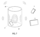
- FIG. 7 schematically illustrates a first implementation example of the flexible wireless charging device.
- the flexible wireless charging device 2 is bent to have a sleeve structure with an accommodation space 20. That is, the shape of the thin-film transmitter coil assembly 21 of the flexible wireless charging device 2 is changeable according to the practical requirements. Since the thin-film transmitter coil assembly 21 has the double-side charging function, the power-receiving device 3 that is located within the accommodation space 20 or located near the flexible wireless charging device 2 can be wirelessly charged by the flexible wireless charging device 2.
- FIG. 8 schematically illustrates a second implementation example of the flexible wireless charging device.
- the flexible wireless charging device 2 is bent to have a U-shaped structure.
- the U-shaped structure may be attached on a wall 6. That is, the shape of the thin-film transmitter coil assembly 21 of the flexible wireless charging device 2 is changeable according to the practical requirements. Since the thin-film transmitter coil assembly 21 has the double-side charging function, the power-receiving device 3 that is located within the U-shaped structure or located near the flexible wireless charging device 2 can be wirelessly charged by the flexible wireless charging device 2.
- FIG. 9 schematically illustrates a third implementation example of the flexible wireless charging device.
- the flexible wireless charging device 2 further comprises two additional thin-film transmitter coil assemblies 21a and 21b connected with the two edges of the thin-film transmitter coil assembly 21, respectively.
- the structures and operating principles of each of the thin-film transmitter coil assemblies 21a and 21b are similar to those of the thin-film transmitter coil assembly 21, and are not redundantly described herein.
- the thin-film transmitter coil assembly 21 is bent to have a sleeve structure.
- the thin-film transmitter coil assemblies 21a and 21b are respectively located at a top side and a bottom side of the sleeve structure. Consequently, a cylindrical structure is defined by the thin-film transmitter coil assemblies 21, 21a and 21b collaboratively.
- the flexible wireless charging device 2 further comprises a bracket 24 and a base 25.
- the bracket 24 is arranged between the cylindrical structure and the base 25 for supporting the cylindrical structure.
- the base 25 is connected with the bracket 24. Through the base 25, the flexible wireless charging device 2 can be placed on a flat surface.
- the electromagnetic wave of the flexible wireless charging device 2 is emitted in a 3D radiation manner. Consequently, plural power-receiving devices 3 within the chargeable distance (e.g., 1 meter or longer) can be wirelessly charged by the flexible wireless charging device 2.
- FIG. 10 is a schematic perspective view illustrating a power-receiving device of the wireless charging system of FIG .1 .
- the power-receiving device 3 comprises the wireless receiving unit 3a and the load 3b.
- the wireless receiving unit 3a of the power-receiving device 3 is a wireless receiver pad
- the load 3b is a mobile phone without the function of being wirelessly charged.
- the wireless receiving unit 3a i.e., the wireless receiver pad
- the load 3b i.e., the mobile phone
- the electric energy from the thin-film transmitter coil assembly 21 of the flexible wireless charging device 2 can be received by the thin-film receiver coil assembly 31 and the receiver module 32 of the wireless receiving unit 3a.
- the mobile phone can be wirelessly charged by the flexible wireless charging device 2 through the wireless receiving unit 3a.
- the present invention provides a flexible wireless charging device and a thin-film coil assembly thereof.
- the structure of the thin-film coil assembly is flexible and slim.
- the shape of the thin-film coil assembly can be varied according to the practical requirements and the operating environments. Consequently, a double-side and long-distance charging function is achievable, and the wireless charging flexibility is enhanced.
- the flexible wireless charging device of the present invention is capable of wirelessly charging the power-receiving device without the need of positioning the wireless receiving terminal of the power-receiving device.
- the flexible wireless charging device and the thin-film coil assembly of the present invention are cost-effective and can be operated at a wider frequency and bandwidth range, the applications are enhanced.
- the flexible wireless charging device and the thin-film coil assembly of the present invention can avoid the interference of the multiple coils, and thus the charging efficiency is enhanced.
Landscapes
- Engineering & Computer Science (AREA)
- Power Engineering (AREA)
- Computer Networks & Wireless Communication (AREA)
- Signal Processing (AREA)
- Charge And Discharge Circuits For Batteries Or The Like (AREA)
Applications Claiming Priority (1)
| Application Number | Priority Date | Filing Date | Title |
|---|---|---|---|
| TW104113889A TW201638980A (zh) | 2015-04-30 | 2015-04-30 | 薄膜線圈元件及其適用之可撓式無線充電裝置與系統 |
Publications (1)
| Publication Number | Publication Date |
|---|---|
| EP3089374A1 true EP3089374A1 (fr) | 2016-11-02 |
Family
ID=54324897
Family Applications (1)
| Application Number | Title | Priority Date | Filing Date |
|---|---|---|---|
| EP15189779.0A Withdrawn EP3089374A1 (fr) | 2015-04-30 | 2015-10-14 | Ensemble bobine à film mince, dispositif et système de charge sans fil |
Country Status (5)
| Country | Link |
|---|---|
| US (1) | US20160322156A1 (fr) |
| EP (1) | EP3089374A1 (fr) |
| JP (1) | JP3201863U (fr) |
| KR (1) | KR20160129672A (fr) |
| TW (1) | TW201638980A (fr) |
Families Citing this family (26)
| Publication number | Priority date | Publication date | Assignee | Title |
|---|---|---|---|---|
| KR101701045B1 (ko) * | 2015-06-09 | 2017-01-31 | 삼성전기주식회사 | 무선 전력 전송용 코일 구조체 및 이를 포함하는 무선 전력 송신 장치 |
| WO2018025051A1 (fr) * | 2016-08-05 | 2018-02-08 | Pilkington Group Limited | Vitrage feuilleté |
| TW201816539A (zh) * | 2016-10-20 | 2018-05-01 | 華碩電腦股份有限公司 | 無線充電結構及其製造方法 |
| US11264837B2 (en) | 2017-02-13 | 2022-03-01 | Nucurrent, Inc. | Transmitting base with antenna having magnetic shielding panes |
| JP7285784B2 (ja) * | 2017-03-17 | 2023-06-02 | エフィシエント パワー コンヴァーション コーポレーション | 大面積スケーラブル高共振ワイヤレス電力コイル |
| US10404093B2 (en) * | 2017-04-26 | 2019-09-03 | Biosense Webster (Israel) Ltd. | Using location transmission signals for charging a wireless medical tool of an electromagnetic navigation system |
| US10848001B2 (en) * | 2017-07-27 | 2020-11-24 | Garrity Power Services Llc | Thin film photovoltaic wireless interface |
| WO2019050933A1 (fr) * | 2017-09-05 | 2019-03-14 | University Of Florida Research Foundation | Transfert d'énergie sans fil à des implants biomédicaux |
| CN109004768B (zh) * | 2018-06-26 | 2022-05-31 | 华为技术有限公司 | 一种无线充电的装置和方法 |
| CN110093831B (zh) * | 2019-05-14 | 2023-10-20 | 华南理工大学 | 一种可卷曲的无线充电路面结构及其制作方法 |
| DE102019211399A1 (de) * | 2019-07-31 | 2021-02-04 | Würth Elektronik eiSos Gmbh & Co. KG | Spulen-Anordnung und Vorrichtung zur drahtlosen elektromagnetischen Energieübertragung |
| CN112498185B (zh) * | 2019-09-16 | 2022-07-05 | 中车株洲电力机车研究所有限公司 | 非接触供电耦合装置、制造方法和应用车辆 |
| TWI775022B (zh) * | 2019-12-16 | 2022-08-21 | 圓凱科技實業股份有限公司 | 可無線充電的墊體及其製法 |
| WO2021167442A1 (fr) * | 2020-02-20 | 2021-08-26 | Nanomalaysia Berhad | Système de distribution d'énergie sans fil |
| US11831173B2 (en) | 2021-11-03 | 2023-11-28 | Nucurrent, Inc. | Wireless power transmission antenna with series coil molecule configuration |
| US11824371B2 (en) | 2021-11-03 | 2023-11-21 | Nucurrent, Inc. | Wireless power transmission antenna with internal repeater and repeater filter |
| US11962337B2 (en) * | 2021-11-03 | 2024-04-16 | Nucurrent, Inc. | Communications demodulation in wireless power transmission system having an internal repeater |
| US11831176B2 (en) | 2021-11-03 | 2023-11-28 | Nucurrent, Inc. | Wireless power transfer systems with substantial uniformity over a large area |
| US11862984B2 (en) | 2021-11-03 | 2024-01-02 | Nucurrent, Inc. | Wireless power receiver with repeater for enhanced power harvesting |
| US11831175B2 (en) | 2021-11-03 | 2023-11-28 | Nucurrent, Inc. | Wireless power transmission antenna with antenna molecules |
| US11831177B2 (en) | 2021-11-03 | 2023-11-28 | Nucurrent, Inc. | Wireless power transmitter with internal repeater and enhanced uniformity |
| US11824373B2 (en) | 2021-11-03 | 2023-11-21 | Nucurrent, Inc. | Wireless power transmission antenna with parallel coil molecule configuration |
| US11955819B2 (en) | 2021-11-03 | 2024-04-09 | Nucurrent, Inc. | Communications modulation in wireless power receiver with multi-coil receiver antenna |
| US11862991B2 (en) | 2021-11-03 | 2024-01-02 | Nucurrent, Inc. | Wireless power transmission antenna with internal repeater and in-coil tuning |
| US11824372B2 (en) | 2021-11-03 | 2023-11-21 | Nucurrent, Inc. | Wireless power transmission antenna with puzzled antenna molecules |
| US11848566B2 (en) | 2021-11-03 | 2023-12-19 | Nucurrent, Inc. | Dual communications demodulation of a wireless power transmission system having an internal repeater |
Citations (2)
| Publication number | Priority date | Publication date | Assignee | Title |
|---|---|---|---|---|
| US20130119929A1 (en) * | 2011-01-18 | 2013-05-16 | Mojo Mobility, Inc. | Multi-dimensional inductive charger and applications thereof |
| US20150097521A1 (en) * | 2012-05-14 | 2015-04-09 | Hitachi Chemical Company, Ltd. | Antenna sheet for non-contact charging device and charging device using the antenna sheet |
Family Cites Families (1)
| Publication number | Priority date | Publication date | Assignee | Title |
|---|---|---|---|---|
| US20130271069A1 (en) * | 2012-03-21 | 2013-10-17 | Mojo Mobility, Inc. | Systems and methods for wireless power transfer |
-
2015
- 2015-04-30 TW TW104113889A patent/TW201638980A/zh unknown
- 2015-09-22 US US14/860,936 patent/US20160322156A1/en not_active Abandoned
- 2015-09-22 KR KR1020150133698A patent/KR20160129672A/ko not_active Application Discontinuation
- 2015-10-14 EP EP15189779.0A patent/EP3089374A1/fr not_active Withdrawn
- 2015-10-20 JP JP2015005293U patent/JP3201863U/ja not_active Expired - Fee Related
Patent Citations (2)
| Publication number | Priority date | Publication date | Assignee | Title |
|---|---|---|---|---|
| US20130119929A1 (en) * | 2011-01-18 | 2013-05-16 | Mojo Mobility, Inc. | Multi-dimensional inductive charger and applications thereof |
| US20150097521A1 (en) * | 2012-05-14 | 2015-04-09 | Hitachi Chemical Company, Ltd. | Antenna sheet for non-contact charging device and charging device using the antenna sheet |
Also Published As
| Publication number | Publication date |
|---|---|
| US20160322156A1 (en) | 2016-11-03 |
| TW201638980A (zh) | 2016-11-01 |
| JP3201863U (ja) | 2016-01-07 |
| KR20160129672A (ko) | 2016-11-09 |
Similar Documents
| Publication | Publication Date | Title |
|---|---|---|
| EP3089374A1 (fr) | Ensemble bobine à film mince, dispositif et système de charge sans fil | |
| JP3203151U (ja) | フレキシブルで格納可能な無線充電デバイス | |
| EP3089375A1 (fr) | Dispositif de charge sans fil et système à divergence d'onde électromagnétique supprimée et efficacité de charge améliorée | |
| US20160322852A1 (en) | Wireless charging device | |
| US10461585B2 (en) | Power-receiving device, wireless power-feeding system including power-receiving device, and wireless communication system including power-receiving device | |
| US9577468B2 (en) | Wireless charging receiving device and wireless charging system using the same | |
| EP3394954B1 (fr) | Antenne pour charge d'énergie sans fil en champ proche | |
| JP5695982B2 (ja) | 電力供給方法 | |
| US20150222126A1 (en) | External or internal receiver for smart mobile devices | |
| EP3089376A1 (fr) | Dispositif de charge sans fil flexible à suspension | |
| JP2018530178A (ja) | 無線充電及びnfc通信のための無線アンテナ、並びにそれを適用した無線端末機 | |
| CN104348223B (zh) | 无线装置中无线充电单元的集成 | |
| CN110620408A (zh) | 具有电磁屏蔽功能的无线充电器 | |
| EP3232451B1 (fr) | Blindage pour un émetteur de puissance sans fil | |
| US20170047785A1 (en) | Wireless power enabled enclosures for mobile devices | |
| TWM510005U (zh) | 無線充電裝置 | |
| US20150076919A1 (en) | Coil type unit for wireless power transmission, wireless power transmission device, electronic device and manufacturing method of coil type unit for wireless power transmission | |
| CN204794286U (zh) | 无线充电装置及系统 | |
| CN204835717U (zh) | 薄膜线圈元件及其适用的可挠式无线充电装置与系统 | |
| TWM507106U (zh) | 可抑制電磁波發散和提升充電效能之無線充電裝置及系統 | |
| CN204835719U (zh) | 无线充电装置 | |
| CN106300574A (zh) | 无线充电装置及系统 | |
| CN106208397A (zh) | 薄膜线圈元件及其适用的可挠式无线充电装置与系统 | |
| US20150028686A1 (en) | Coil type unit for wireless power transmission, wireless power transmission device, electronic device and manufacturing method of coil type unit for wireless power transmission | |
| KR101899476B1 (ko) | 무선 충전 모듈 및 이를 구비하는 모바일 단말기 |
Legal Events
| Date | Code | Title | Description |
|---|---|---|---|
| PUAI | Public reference made under article 153(3) epc to a published international application that has entered the european phase |
Free format text: ORIGINAL CODE: 0009012 |
|
| AK | Designated contracting states |
Kind code of ref document: A1 Designated state(s): AL AT BE BG CH CY CZ DE DK EE ES FI FR GB GR HR HU IE IS IT LI LT LU LV MC MK MT NL NO PL PT RO RS SE SI SK SM TR |
|
| AX | Request for extension of the european patent |
Extension state: BA ME |
|
| STAA | Information on the status of an ep patent application or granted ep patent |
Free format text: STATUS: THE APPLICATION IS DEEMED TO BE WITHDRAWN |
|
| 18D | Application deemed to be withdrawn |
Effective date: 20170503 |