EP3089253A1 - Fuel battery system - Google Patents
Fuel battery system Download PDFInfo
- Publication number
- EP3089253A1 EP3089253A1 EP14875461.7A EP14875461A EP3089253A1 EP 3089253 A1 EP3089253 A1 EP 3089253A1 EP 14875461 A EP14875461 A EP 14875461A EP 3089253 A1 EP3089253 A1 EP 3089253A1
- Authority
- EP
- European Patent Office
- Prior art keywords
- cell
- oxidizing gas
- control
- fuel cell
- resistance value
- Prior art date
- Legal status (The legal status is an assumption and is not a legal conclusion. Google has not performed a legal analysis and makes no representation as to the accuracy of the status listed.)
- Granted
Links
- 239000000446 fuel Substances 0.000 title claims abstract description 123
- 230000001590 oxidative effect Effects 0.000 claims abstract description 173
- 229920000554 ionomer Polymers 0.000 claims abstract description 24
- 239000003054 catalyst Substances 0.000 claims abstract description 12
- 239000004020 conductor Substances 0.000 claims abstract description 12
- 239000007789 gas Substances 0.000 claims description 213
- 239000002737 fuel gas Substances 0.000 claims description 41
- 239000003792 electrolyte Substances 0.000 claims description 13
- 239000012528 membrane Substances 0.000 claims description 8
- 238000010248 power generation Methods 0.000 abstract description 26
- 230000007423 decrease Effects 0.000 abstract description 6
- 239000000498 cooling water Substances 0.000 description 36
- QVGXLLKOCUKJST-UHFFFAOYSA-N atomic oxygen Chemical compound [O] QVGXLLKOCUKJST-UHFFFAOYSA-N 0.000 description 13
- 230000003247 decreasing effect Effects 0.000 description 13
- 239000001301 oxygen Substances 0.000 description 13
- 229910052760 oxygen Inorganic materials 0.000 description 13
- 238000003487 electrochemical reaction Methods 0.000 description 6
- 101100368959 Arabidopsis thaliana TFCB gene Proteins 0.000 description 5
- 230000035699 permeability Effects 0.000 description 5
- 238000002474 experimental method Methods 0.000 description 4
- 239000001257 hydrogen Substances 0.000 description 3
- 229910052739 hydrogen Inorganic materials 0.000 description 3
- UFHFLCQGNIYNRP-UHFFFAOYSA-N Hydrogen Chemical compound [H][H] UFHFLCQGNIYNRP-UHFFFAOYSA-N 0.000 description 2
- 230000032683 aging Effects 0.000 description 2
- 230000008859 change Effects 0.000 description 2
- 230000007246 mechanism Effects 0.000 description 2
- BASFCYQUMIYNBI-UHFFFAOYSA-N platinum Chemical compound [Pt] BASFCYQUMIYNBI-UHFFFAOYSA-N 0.000 description 2
- 238000011144 upstream manufacturing Methods 0.000 description 2
- OKTJSMMVPCPJKN-UHFFFAOYSA-N Carbon Chemical compound [C] OKTJSMMVPCPJKN-UHFFFAOYSA-N 0.000 description 1
- 230000009471 action Effects 0.000 description 1
- 230000008901 benefit Effects 0.000 description 1
- 230000002457 bidirectional effect Effects 0.000 description 1
- 229910052799 carbon Inorganic materials 0.000 description 1
- 230000005494 condensation Effects 0.000 description 1
- 238000009833 condensation Methods 0.000 description 1
- 238000009792 diffusion process Methods 0.000 description 1
- 230000000694 effects Effects 0.000 description 1
- 230000006870 function Effects 0.000 description 1
- XLYOFNOQVPJJNP-ZSJDYOACSA-N heavy water Substances [2H]O[2H] XLYOFNOQVPJJNP-ZSJDYOACSA-N 0.000 description 1
- -1 hydrogen ions Chemical class 0.000 description 1
- 229910052697 platinum Inorganic materials 0.000 description 1
- 238000005086 pumping Methods 0.000 description 1
- XLYOFNOQVPJJNP-UHFFFAOYSA-N water Chemical compound O XLYOFNOQVPJJNP-UHFFFAOYSA-N 0.000 description 1
Images


Classifications
-
- H—ELECTRICITY
- H01—ELECTRIC ELEMENTS
- H01M—PROCESSES OR MEANS, e.g. BATTERIES, FOR THE DIRECT CONVERSION OF CHEMICAL ENERGY INTO ELECTRICAL ENERGY
- H01M8/00—Fuel cells; Manufacture thereof
- H01M8/04—Auxiliary arrangements, e.g. for control of pressure or for circulation of fluids
- H01M8/04298—Processes for controlling fuel cells or fuel cell systems
- H01M8/04694—Processes for controlling fuel cells or fuel cell systems characterised by variables to be controlled
- H01M8/04746—Pressure; Flow
- H01M8/04753—Pressure; Flow of fuel cell reactants
-
- H—ELECTRICITY
- H01—ELECTRIC ELEMENTS
- H01M—PROCESSES OR MEANS, e.g. BATTERIES, FOR THE DIRECT CONVERSION OF CHEMICAL ENERGY INTO ELECTRICAL ENERGY
- H01M8/00—Fuel cells; Manufacture thereof
- H01M8/04—Auxiliary arrangements, e.g. for control of pressure or for circulation of fluids
- H01M8/04298—Processes for controlling fuel cells or fuel cell systems
- H01M8/04313—Processes for controlling fuel cells or fuel cell systems characterised by the detection or assessment of variables; characterised by the detection or assessment of failure or abnormal function
- H01M8/04537—Electric variables
- H01M8/04544—Voltage
- H01M8/04559—Voltage of fuel cell stacks
-
- H—ELECTRICITY
- H01—ELECTRIC ELEMENTS
- H01M—PROCESSES OR MEANS, e.g. BATTERIES, FOR THE DIRECT CONVERSION OF CHEMICAL ENERGY INTO ELECTRICAL ENERGY
- H01M8/00—Fuel cells; Manufacture thereof
- H01M8/04—Auxiliary arrangements, e.g. for control of pressure or for circulation of fluids
- H01M8/04298—Processes for controlling fuel cells or fuel cell systems
- H01M8/04313—Processes for controlling fuel cells or fuel cell systems characterised by the detection or assessment of variables; characterised by the detection or assessment of failure or abnormal function
- H01M8/04537—Electric variables
- H01M8/04634—Other electric variables, e.g. resistance or impedance
-
- H—ELECTRICITY
- H01—ELECTRIC ELEMENTS
- H01M—PROCESSES OR MEANS, e.g. BATTERIES, FOR THE DIRECT CONVERSION OF CHEMICAL ENERGY INTO ELECTRICAL ENERGY
- H01M8/00—Fuel cells; Manufacture thereof
- H01M8/04—Auxiliary arrangements, e.g. for control of pressure or for circulation of fluids
- H01M8/04298—Processes for controlling fuel cells or fuel cell systems
- H01M8/04694—Processes for controlling fuel cells or fuel cell systems characterised by variables to be controlled
- H01M8/04858—Electric variables
- H01M8/04895—Current
-
- H—ELECTRICITY
- H01—ELECTRIC ELEMENTS
- H01M—PROCESSES OR MEANS, e.g. BATTERIES, FOR THE DIRECT CONVERSION OF CHEMICAL ENERGY INTO ELECTRICAL ENERGY
- H01M8/00—Fuel cells; Manufacture thereof
- H01M8/10—Fuel cells with solid electrolytes
- H01M2008/1095—Fuel cells with polymeric electrolytes
-
- Y—GENERAL TAGGING OF NEW TECHNOLOGICAL DEVELOPMENTS; GENERAL TAGGING OF CROSS-SECTIONAL TECHNOLOGIES SPANNING OVER SEVERAL SECTIONS OF THE IPC; TECHNICAL SUBJECTS COVERED BY FORMER USPC CROSS-REFERENCE ART COLLECTIONS [XRACs] AND DIGESTS
- Y02—TECHNOLOGIES OR APPLICATIONS FOR MITIGATION OR ADAPTATION AGAINST CLIMATE CHANGE
- Y02E—REDUCTION OF GREENHOUSE GAS [GHG] EMISSIONS, RELATED TO ENERGY GENERATION, TRANSMISSION OR DISTRIBUTION
- Y02E60/00—Enabling technologies; Technologies with a potential or indirect contribution to GHG emissions mitigation
- Y02E60/30—Hydrogen technology
- Y02E60/50—Fuel cells
Definitions
- the present invention relates to a fuel cell system.
- a fuel cell system is known in the art, which system is provided with: a cell for fuel cell, which cell has a membrane electrode assembly which is provided with an electrolyte and a cathode and anode which are respectively arranged at two sides of the electrolyte and an oxidizing gas passage which feeds an oxidizing gas to the cathode; an oxidizing gas feed path which is connected to an inlet of the oxidizing gas passage; and an oxidizing gas feeder which is arranged in the oxidizing gas feed path and feeds oxidizing gas to the cathode.
- moistness of a cell for fuel cell in particular an electrolyte or electrodes
- the moistness of the cell is expressed by an output current value of the cell. That is, as the moistness of the cell becomes lower, the output current value of the cell becomes smaller.
- oxidizing gas when oxidizing gas is sent to the cell, the oxidizing gas which flows out from the cell or cathode off-gas carries off moisture from the cell. If the amount of oxidizing gas which is sent to the cell becomes smaller, the amount of moisture which is carried off from the cell becomes smaller.
- a fuel cell system in which the oxidizing gas feeder is controlled to reduce the amount of oxidizing gas which is sent to the cell if the output current value of the cell is smaller than a predetermined threshold current value (see PTL 1).
- a predetermined threshold current value see PTL 1.
- PTL 1 merely suppresses carrying off of moisture from the cell. For this reason, there may be a problem that a long time is required for increasing or restoring the power generation quantity of the cell.
- a fuel cell system comprising: a cell for fuel cell, the cell having a membrane electrode assembly provided with an electrolyte and a cathode and anode respectively arranged at two sides of the electrolyte and an oxidizing gas passage configured to feed an oxidizing gas to the cathode; an oxidizing gas feed path connected to an inlet of the oxidizing gas passage; and an oxidizing gas feeder arranged in the oxidizing gas feed path and configured to feed oxidizing gas to the cathode, wherein the cathode includes a conductive material, catalyst, and ionomer which covers the conductive material and catalyst, and wherein, if an output voltage value of the cell is lower than a predetermined threshold voltage value and an electrical resistance value of the cell is higher than a predetermined threshold resistance value, the oxidizing gas feeder is controlled to perform control for increasing an oxidizing gas amount which increases an amount of oxidizing gas sent to the cell.
- a fuel cell system A is provided with a cell 1 for fuel cell.
- the cell 1 has a membrane electrode assembly 2.
- the membrane electrode assembly 2 is provided with a membrane-like electrolyte 2e, an anode 2a which is formed at one side of the electrolyte 2e, and a cathode 2c which is formed at the other side of the electrolyte 2e.
- the anode 2a and cathode 2c as shown in FIG. 1 , are electrically connected through an DC/AC converter 3 to for example an electric motor 4 for driving a vehicle on one hand, and are electrically connected through an AC/AC converter 5 to an electric accumulator 6 on the other hand.
- the electric accumulator 6 is comprised of a battery. Further, as shown in FIG. 1 and FIG. 2 , inside the cell 1, a fuel gas passage 10 for feeding fuel gas to the anode 2a and an oxidizing gas passage 20 which feeds oxidizing gas to the cathode 2c are formed. Inside the cell 1, further, the cell 1 is formed with a cooling water passage 30 for feeding cooling water to the cell 1.
- the fuel cell system A which is shown in FIG. 1 is provided with a plurality of cells 1. These cells 1 are stacked in series with each other to form a fuel cell stack. In this case, the above-mentioned fuel gas passages 10, oxidizing gas passages 20, and cooling water passages 30 are respectively connected with each other.
- a fuel gas feed path 11 is connected.
- the fuel gas feed path 11 is connected to a fuel gas source 12.
- the fuel gas is comprised of hydrogen and the fuel gas source 12 is comprised of a hydrogen tank.
- a fuel gas control valve 13 which controls an amount of fuel gas which flows through the inside of the fuel gas feed path 11 is arranged.
- an anode off-gas passage 14 is connected. Inside the anode off-gas passage 14, an anode off-gas control valve 15 which controls an amount of anode off-gas which flows through the inside of the anode off-gas passage 14 is arranged.
- an oxidizing gas feed path 21 is connected at an inlet of the oxidizing gas passage 20, an oxidizing gas feed path 21 is connected.
- the oxidizing gas feed path 21 is connected to an oxidizing gas source 22.
- the oxidizing gas is comprised of air and the oxidizing gas source 22 is comprised of the atmosphere.
- an oxidizing gas feeder or compressor 23 which pumps out the oxidizing gas is arranged inside the oxidizing gas feed path 21, a cathode off-gas passage 24 is connected.
- the compressor 23 is driven, the oxidizing gas inside the oxidizing gas source 22 is fed through the oxidizing gas feed path 21 to the oxidizing gas passage 20 inside the cell 1.
- a gas which flows out from the oxidizing gas passage 20, that is, a cathode off-gas flows into the cathode off-gas passage 24.
- the cell 1 is comprised of a cell for fuel cell of an opposite flow type. That is, the inlet of the fuel gas passage 10 and the outlet of the oxidizing gas passage 20 adjoin each other, the outlet of the fuel gas passage 10 and inlet of the oxidizing gas passage 20 adjoin each other, and therefore the fuel gas and oxidizing gas flow inside the cell 1 substantially in parallel and in reverse directions to each other.
- the cell 1 is comprised of a cell for fuel cell of a concurrent flow type.
- the cell 1 is comprised of a cell for fuel cell of a perpendicular flow type. That is, the fuel gas and oxidizing gas flow inside the cell 1 substantially perpendicular to each other.
- a cooling water feed path 31 At an inlet of the cooling water passage 30, one end of a cooling water feed path 31 is connected. At an outlet of the cooling water feed path 31, the other end of the cooling water feed path 31 is connected.
- a cooling water pump 32 for pumping out cooling water and a radiator 33 are arranged inside the cooling water feed path 31 inside the cooling water feed path 31, a cooling water pump 32 for pumping out cooling water and a radiator 33 are arranged.
- the cooling water feed path 31 upstream of the radiator 33 and the cooling water feed path 31 between the radiator 33 and the cooling water pump 32 are connected with each other by a radiator bypass passage 34.
- a radiator bypass control valve 35 which controls an amount of cooling water which flows through the inside of the radiator bypass passage 34 is provided.
- the radiator bypass control valve 35 is comprised of a three-way valve and is arranged at an inlet of the radiator bypass passage 34.
- the cooling water which is discharged from the cooling water pump 32 flows through the cooling water feed path 31 to the cooling water passage 30 in the cell 1, then passes through the cooling water passage 30 to flow into the cooling water feed path 31 and passes through the radiator 33 or radiator bypass passage 34 to be returned to the cooling water pump 32.
- an amount of the cooling water which is sent by the radiator bypass control valve 35 to the radiator 33 is increased, a cooling water temperature is lowered and therefore a temperature of the cell 1 is lowered.
- cooling water feed path 31, cooling water pump 32, and radiator bypass control valve 35 act as a fuel cell temperature controller which controls the fuel cell temperature.
- the electronic control unit 50 is comprised of a digital computer which is provided with components which are connected with each other by a bidirectional bus 51 such as a ROM (read only memory) 52, RAM (random access memory) 53, CPU (microprocessor) 54, input port 55, and output port 56.
- ROM read only memory
- RAM random access memory
- CPU microprocessor
- input port 55 input port 55
- output port 56 output port 56.
- a temperature sensor 40 which detects a temperature of the cooling water is attached.
- the cooling water temperature which is detected by the temperature sensor 40 expresses a temperature of the cell 1.
- a voltmeter 41 and electrical resistance meter 42 which respectively detect an output voltage value of the cell 1 and electrical resistance value are provided.
- the output signals of the temperature sensor 40, voltmeter 41, and electrical resistance meter 42 are input through corresponding AD converters 57 to the input port 55.
- the output port 56 is connected through corresponding drive circuits 58 through the fuel gas control valve 13, anode off-gas control valve 15, compressor 23, cooling water pump 32, and radiator bypass control valve 35.
- FIG. 3 shows a partially enlarged cross-sectional view of the cathode 2c.
- the cathode 2c includes a conductive material 2c1 in a form of particulates, an ionomer 2c2 which covers the conductive material 2c1, and a catalyst 2c3 in a form of particulates which is carried on the conductive material 2c1.
- the conductive material 2c1 is comprised of carbon
- the ionomer 2c2 is comprised of an electrolyte which is the same as or similar to the electrolyte 2e
- the catalyst 2c3 is comprised of platinum.
- 2c4 shows a clearance which is formed at the cathode 2c.
- the hydrogen ions H + pass through the electrolyte 2e and reach the cathode 2c, in particular a surface of the catalyst 2c3.
- the oxygen O 2 passes through the ionomer 2c2 and reaches the surface of the catalyst 2c3.
- it passes through the clearance which is formed at the cathode 2c ( FIG. 3 ) and reaches the catalyst 2c3.
- the electrons e - are conducted through the conductive material 2c1 and reach the surface of the catalyst 2c3.
- the above-mentioned electrochemical reaction (1) occurs and moisture is generated.
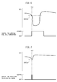
- FIG. 5 shows results of experiments which show a relationship between a relative humidity (%) of the atmosphere around an ionomer and an oxygen solubility of the ionomer.
- This relative humidity expresses moistness of ionomer.
- the oxygen solubility of the ionomer falls.
- the oxygen permeability of the ionomer is expressed by a product of the oxygen solubility of the ionomer and an oxygen diffusion coefficient of the ionomer. Therefore, if the moistness of the ionomer falls, the oxygen permeability of the ionomer falls.
- the power generation quantity of the cell 1 can be increased or restored.
- moistness of the cell 1 is represented by the electrical resistance value of the cell 1. That is, as the moistness of the cell 1 becomes lower, the electrical resistance value of the cell 1 becomes larger.
- the fuel cell system A is controlled to make an output current value of the cell 1 equal to a target current value which is determined based on a target power generation quantity of the cell 1. Therefore, considering the fact that the power generation quantity of the cell 1 is represented by a product of an output current value and an output voltage value of the cell 1, it can be the that a power generation quantity of the cell 1 when the output voltage value is low is decreased compared with that when the output voltage value is high, under the same output current.
- the oxidizing gas feeder 23 is controlled to perform control for increasing an oxidizing gas amount which increases an amount of oxidizing gas sent to the cell 1.
- the amount or concentration of oxidizing gas in the oxidizing gas passage 20 is increased and thereby the amount of oxidizing gas which passes through the ionomer and reaches the cathode 2c is increased. Therefore, the power generation quantity of the cell 1 is quickly increased.
- the power generation quantity of the cell 1 being increased means that an amount of moisture which is produced by the above-mentioned electrochemical reaction (1) is increased. As a result, moistness of the cell 1 also rises or is restored. If the moistness of the cell 1 raises, the oxygen permeability of the ionomer rises, therefore the power generation quantity of the cell 1 is further increased.
- the power generation quantity of the cell 1 is further reduced at the beginning of control for decreasing the oxidizing gas amount and then is increased. That is, in control for decreasing the oxidizing gas amount, a long time is required for making the power generation quantity of the cell 1 increase.
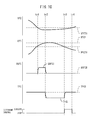
- FIG. 6 shows results of experiments which show an output voltage value VFC of the cell 1 when the above-mentioned control for lowering a fuel cell temperature is performed.
- ta1 shows a time when the output voltage value VFC of the cell 1 becomes lower than a predetermined threshold voltage value VFCTH and the electrical resistance value of the cell 1 becomes higher than a predetermined threshold resistance value.
- the output voltage value VFC of the cell 1 continues to fall for a while even after the control for lowering the fuel cell temperature is started, and starts to rise after a while. That is, in this case, a long time is required for increasing or restoring the power generation quantity of the cell 1.
- FIG. 7 shows results of experiments which show an output voltage value VFC of the cell 1 when control for increasing an oxidizing gas amount is performed.
- tb1 shows a time when the output voltage value VFC of the cell 1 becomes lower than a predetermined threshold voltage value VFCTH and the electrical resistance value of the cell 1 becomes higher than a predetermined threshold resistance value.
- the time required from when the output voltage value VFC becomes lower than the threshold voltage value VFCTH to when it is restored was about 2 minutes in the example of FIG. 6 , but was about 1 second in the example of FIG. 7 .
- an output voltage value VFC of the cell 1 becomes lower than a predetermined threshold voltage value VFCTH and an electrical resistance value RFC of the cell 1 becomes higher than a predetermined threshold resistance value RFCTH
- the above-mentioned control for increasing the oxidizing gas amount is started.
- an oxidizing gas amount QOFC which is sent to the cell 1 is increased from a base oxidizing gas amount QOFCB to an increased oxidizing gas amount QOFCI and held there.
- the base oxidizing gas amount QOFCB is an amount of oxidizing gas at the time of normal control where control for increasing the oxidizing gas amount is not performed and is determined in accordance with, for example, a target power generation quantity of the cell 1.
- the control for increasing the oxidizing gas amount is stopped.
- the oxidizing gas amount QOFC which is sent to the cell 1 is returned to the base oxidizing gas amount QOFCB.
- the electrical resistance value RFC of the cell 1 has been lower than the threshold resistance value RFCTH and therefore is restored. That is, in this way, control for increasing the oxidizing gas amount is temporarily performed whereby the output voltage value VFC and electrical resistance value RFC of the cell 1 are restored.
- the temperature TFC of the cell 1 falls from a base fuel cell temperature TFCB to a lowered fuel cell temperature TFCBL and is held there.
- the base fuel cell temperature TFCB is a fuel cell temperature at the time of normal control where the control for lowering the fuel cell temperature is not performed and is controlled so as not to exceed, for example, a certain value.
- the control for lowering the fuel cell temperature is performed using one or both of lowering the temperature of the cooling water and increasing the amount of cooling water.
- the control for lowering the fuel cell temperature is stopped. As a result, the temperature of the cell 1 is returned to the base fuel cell temperature TFCB.
- the output voltage value VFC of the cell 1 becomes equal to or larger than the threshold voltage value VFCTH, that is, if the output voltage value VFC is restored, the above-mentioned different control is stopped.
- the electrical resistance value RFC of the cell 1 becomes higher than the threshold resistance value RFCTH and then the output voltage value VFC of the cell 1 becomes lower than the threshold voltage value VFCTH.
- the output voltage value VFC becomes lower than the threshold voltage value VFCTH and then the electrical resistance value RFC becomes higher than the threshold resistance value RFCTH.
- the output voltage value of the cell 1 and electrical resistance value depend on the target current value or output current value of the cell 1 and the temperature of the cell 1.
- the threshold voltage value VFCTH and the threshold resistance value RFCTH are determined in advance as functions of, for example, the target current value of the cell 1 and the temperature of the cell 1 and are stored in the form of maps in the ROM 52.
- the output voltage value and electrical resistance value of the cell 1 can vary in accordance with the extent of aging of the cell 1. Therefore, in the other embodiment according to the present invention, the threshold voltage value VFCTH and the threshold resistance value RFCTH are corrected by the extent of aging of the cell 1.
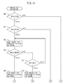
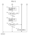
- FIG. 11 and FIG. 12 show a routine for performing control for restoration of the above-mentioned embodiment according to the present invention. This routine is performed by interruption every certain time.
- step 100 it is judged if the output voltage value VFC of the cell 1 is lower than the threshold voltage value VFCTH. If VFC ⁇ VFCTH, the processing cycle is ended. If VFC ⁇ VFCTH, next the routine proceeds to step 101 where it is judged if the electrical resistance value RFC of the cell 1 is higher than the threshold resistance value RFCTH. If RFC>RFCTH, next the routine proceeds to step 102 where control for increasing the oxidizing gas amount is started.
- step 103 it is judged if the output voltage value VFC of the cell 1 is equal to or larger than the threshold voltage value VFCTH. If VFC ⁇ VFCTH, that is, if the output voltage value VFC is restored, next the routine proceeds to step 104 where control for increasing the oxidizing gas amount is stopped. Next, the processing cycle is ended. As opposed to this, if VFC ⁇ VFCTH, that is, if the output voltage value VFC has not yet been restored, the routine proceeds to step 105 where it is judged if the electrical resistance value RFC of the cell 1 is higher than the upper limit resistance value RFC1. If RFC ⁇ RFC1, the routine returns to step 102 where control for increasing the oxidizing gas amount is continued. If RFC>RFC1, next, the routine proceeds to step 106 where control for increasing the oxidizing gas amount is stopped. Next, the routine proceeds to step 107.
- step 107 the control for lowering the fuel cell temperature is started.
- step 108 it is judged if the electrical resistance value RFC of the cell 1 is equal to or smaller than a threshold resistance value RFCTH. If RFC>RFCTH, that is, if the electrical resistance value RFC has not yet been restored, the routine returns to step 107 where the control for lowering the fuel cell temperature is continued. If RFC ⁇ RFCTH, that is, if the electrical resistance value RFC is restored, next the routine proceeds to step 109 where the control for lowering the fuel cell temperature is stopped. At the next step 110, it is judged if the output voltage value VFC of the cell 1 is equal to or larger than the threshold voltage value VFCTH.
- VFC ⁇ VFCTH the processing cycle is ended.
- step 101 and step 110 if VFC ⁇ VFCTH, that is, if VFC ⁇ VFCTH and RFC ⁇ RFCTH, the routine proceeds to step 111 where the above-mentioned different processing is performed.
- FIG. 13 shows another embodiment according to the present invention.
- a back pressure control valve 25 which controls a pressure inside the cathode off-gas passage 24, that is, a back pressure of the cell 1, is arranged inside the cathode off-gas passage 24.
- the back pressure control valve 25 is usually controlled so that the back pressure of the cell 1 is held constant. If an opening degree of the back pressure control valve 25 is made smaller, the back pressure of the cell 1 raises.
- control for raising a back pressure which rises the back pressure of the cell 1 is performed in addition to the above-mentioned control for increasing the oxidizing gas amount.
- the control for raising the back pressure is performed by making the opening degree of the back pressure control valve 25 smaller. If control for increasing the oxidizing gas amount and control for raising the back pressure are performed, the amount or concentration of the oxidizing gas at the cell 1, in particular around the cathode 2c, is further increased. As a result, it is possible to further quickly increase or restore the power generation quantity of the cell 1.
- control for raising the back pressure is started.
- the back pressure PB of the fuel cell 1 is raised from a base back pressure PBB to a raised back pressure PBR and held there. If control for raising the back pressure is performed before the oxidizing gas amount QOFC is increased, the amount of oxidizing gas around the cathode 2c of the fuel cell 1 conversely is liable to decrease. Therefore, in the example which is shown in FIG. 14 , control for raising the back pressure is started after the oxidizing gas amount QOFC is increased.
- the base back pressure PBB is a back pressure at the time of normal control where control for raising the back pressure is not performed and is determined in accordance with an amount of oxidizing gas from the compressor 23.
- the control for increasing the oxidizing gas amount and the control for raising the back pressure are stopped.
- the oxidizing gas amount QOFC which is sent to the fuel cell 1 is returned to the base oxidizing gas amount QOFCB and the back pressure PB of the fuel cell 1 is returned to the base back pressure PBB.
- the electrical resistance value RFC of the fuel cell 1 is lower than the threshold resistance value RFCTH and therefore is restored.
- the oxidizing gas amount QOFC which is sent to the fuel cell 1 is returned to the base oxidizing gas amount QOFCB, and the back pressure PB of the fuel cell 1 is returned to the base back pressure PBB. Further, at the time tg3, the control for lowering the fuel cell temperature is started. As a result, the temperature TFC of the fuel cell 1 is lowered from the base fuel cell temperature TFCB to the lowered fuel cell temperature TFCBL and held there. As a result, the output voltage value VFC gradually rises and the electrical resistance value RFC gradually falls.
- the control for lowering the fuel cell temperature is stopped. As a result, the temperature of the fuel cell 1 is returned to the base fuel cell temperature TFCB.
- the output voltage value VFC of the fuel cell 1 is lower than the threshold voltage value VFCTH while the electrical resistance value RFC of the fuel cell 1 becomes equal to or smaller than the threshold resistance value RFCTH, that is, while the electrical resistance value RFC is restored, the above-mentioned different control, such as different control for eliminating flooding, is performed.
- the output voltage value VFC of the fuel cell 1 becomes equal to or larger than the threshold voltage value VFCTH, that is, if the output voltage value VFC is restored, the above-mentioned different control is stopped.
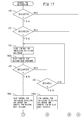
- FIG. 17 and FIG. 18 show a routine for performing control for restoration of the above-mentioned other embodiment according to the present invention.
- This routine is performed by interruption every certain time. Referring to FIG. 17 and FIG. 18 , at step 100, it is judged if the output voltage value VFC of the fuel cell 1 is lower than the threshold voltage value VFCTH. If VFC ⁇ VFCTH, the processing cycle is ended. If VFC ⁇ VFCTH, next the routine proceeds to step 101 where it is judged if the electrical resistance value RFC of the fuel cell 1 is higher than the threshold resistance value RFCTH. If RFC>RFCTH, next the routine proceeds to step 102 where control for increasing the oxidizing gas amount is started.
- the oxidizing gas amount QOFC is increased up to the increased oxidizing gas amount QOFCI, then control for raising the back pressure is started.
- the next step 103 it is judged if the output voltage value VFC of the fuel cell 1 is equal to or larger than the threshold voltage value VFCTH. If VFC ⁇ VFCTH, that is, if the output voltage value VFC is restored, next the routine proceeds to step 104a where control for increasing the oxidizing gas amount and control for raising the back pressure are stopped. Next, the processing cycle is ended.
- step 105 it is judged if the electrical resistance value RFC of the fuel cell 1 is higher than the upper limit resistance value RFC1. If RFC ⁇ RFC1, the routine returns to step 102 where control for increasing the oxidizing gas amount and control for raising the back pressure are continued. If RFC>RFC1, next the routine proceeds to step 106a where control for increasing the oxidizing gas amount and control for raising the back pressure are stopped. Next, the routine proceeds to step 107.
- step 107 the control for lowering the fuel cell temperature is started.
- step 108 it is judged if the electrical resistance value RFC of the fuel cell 1 is equal to or smaller than the threshold resistance value RFCTH. If RFC>RFCTH, that is, if the electrical resistance value RFC has still not been restored, the routine returns to step 107 where the control for lowering the fuel cell temperature is continued. If RFC ⁇ RFCTH, that is, if the electrical resistance value RFC is restored, next the routine proceeds to step 109 where the control for lowering the fuel cell temperature is stopped. At the next step 110, it is judged if the output voltage value VFC of the fuel cell 1 is equal to or larger than the threshold voltage value VFCTH.
- VFC ⁇ VFCTH the processing cycle is ended. If, at step 101 and step 110, VFC ⁇ VFCTH, that is, if VFC ⁇ VFCTH and RFC ⁇ RFCTH, the routine proceeds to step 111 where the above-mentioned different processing is performed.
- the oxidizing gas amount QOFC which is sent to the fuel cell 1 is continuously increased.
- the oxidizing gas amount QOFC is intermittently increased. That is, the oxidizing gas amount QOFC is increased from the base oxidizing gas amount QOFCB to the increased oxidizing gas amount QOFCI and held there, and is then returned to the base oxidizing gas amount QOFCB if a holding time tFCI elapses.
- the action of increasing the oxidizing gas amount is performed for the number of times of increase NFCI.
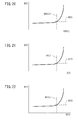
- the increased oxidizing gas amount QOFCI becomes greater than an upper limit gas amount QOFCI1
- the electrical resistance value RFC of the fuel cell 1 will become higher than the upper limit resistance value RFC1. Therefore, the increased oxidizing gas amount QOFCI is set to be equal to or smaller than the upper limit amount QOFCI1.
- the holding time tFCI becomes longer than an upper limit time tFCI1, the electrical resistance value RFC of the fuel cell 1 becomes higher than the upper limit resistance value RFC1. Therefore, the holding time tFCI is set to be equal to or shorter than the upper limit time tFCI1.
- the number of times of increase NFCI becomes greater than an upper limit value NFCI1, the electrical resistance value RFC of the fuel cell 1 becomes higher than the upper limit resistance value RFC1. Therefore, the number of times of increase NFCI is set to be equal to or smaller than the upper limit value NFCI1.
- the oxidizing gas amount QOFC which is sent to the fuel cell 1 is returned to the base oxidizing gas amount QOFCB.
- control for decreasing an oxidizing gas is performed to make the oxidizing gas amount QOFC smaller than the base oxidizing gas amount QOFCB. If control for decreasing the oxidizing gas is performed, the amount of moisture which the cathode off-gas carries off from the fuel cell 1 is decreased, so the moistness of the fuel cell 1 is raised.
- the other embodiment of the fuel cell system A is further provided with a recirculation passage which connects the anode off-gas passage 14 upstream of the anode off-gas control valve 15 and the fuel gas feed path 11 downstream of the fuel gas control valve 13 with each other, and an anode off-gas pump which is arranged in the recirculation passage. Part or all of the anode off-gas in the anode off-gas passage 14 is returned by the anode off-gas pump through the recirculation passage to the fuel gas feed path 11.
- the anode off-gas contains moisture. Therefore, this moisture is returned to the inside of the fuel cell 1 together with the gas by returning the anode off-gas in the anode off-gas passage 14 to the fuel gas feed path 11 as in the other embodiment of the fuel cell system A. As a result, the moistness of the fuel cell 1 does not easily fall.
- the anode off-gas passage 14 and the fuel gas feed path 11 are not connected with each other. Therefore, the anode off-gas flows through the anode off-gas passage 14 without being returned from the anode off-gas passage 14 to the fuel gas feed path 11.
- This enables the configuration of the fuel cell system A to simplify and enables the cost lower.
- the moisture which is contained in the anode off-gas is not returned to the fuel cell 1. For this reason, in the fuel cell systems A which are shown in FIG. 1 and FIG. 13 , the moistness of the fuel cell 1 easily falls.
- control for increasing the oxidizing gas amount is performed if the output voltage value of the fuel cell 1 falls and the moistness of the fuel cell 1 falls.
- the present invention can be applied to the above-mentioned other embodiment of the fuel cell system A as well.
Abstract
Description
- The present invention relates to a fuel cell system.
- A fuel cell system is known in the art, which system is provided with: a cell for fuel cell, which cell has a membrane electrode assembly which is provided with an electrolyte and a cathode and anode which are respectively arranged at two sides of the electrolyte and an oxidizing gas passage which feeds an oxidizing gas to the cathode; an oxidizing gas feed path which is connected to an inlet of the oxidizing gas passage; and an oxidizing gas feeder which is arranged in the oxidizing gas feed path and feeds oxidizing gas to the cathode.
- If moistness of a cell for fuel cell, in particular an electrolyte or electrodes, becomes lower, power generation quantity or efficiency of the cell is liable to become lower. Here, the moistness of the cell is expressed by an output current value of the cell. That is, as the moistness of the cell becomes lower, the output current value of the cell becomes smaller. On the other hand, when oxidizing gas is sent to the cell, the oxidizing gas which flows out from the cell or cathode off-gas carries off moisture from the cell. If the amount of oxidizing gas which is sent to the cell becomes smaller, the amount of moisture which is carried off from the cell becomes smaller.
- Therefore, a fuel cell system is known in the art, in which the oxidizing gas feeder is controlled to reduce the amount of oxidizing gas which is sent to the cell if the output current value of the cell is smaller than a predetermined threshold current value (see PTL 1). As a result, the amount of moisture which is carried off by the cathode off-gas is decreased and therefore the moistness of the cell is gradually raised, that is, is restored.
- PTL 1: Japanese Patent Publication No.
2011-222176A - However,
PTL 1 merely suppresses carrying off of moisture from the cell. For this reason, there may be a problem that a long time is required for increasing or restoring the power generation quantity of the cell. Solution to Problem - According to the present invention, there is provided a fuel cell system comprising: a cell for fuel cell, the cell having a membrane electrode assembly provided with an electrolyte and a cathode and anode respectively arranged at two sides of the electrolyte and an oxidizing gas passage configured to feed an oxidizing gas to the cathode; an oxidizing gas feed path connected to an inlet of the oxidizing gas passage; and an oxidizing gas feeder arranged in the oxidizing gas feed path and configured to feed oxidizing gas to the cathode, wherein the cathode includes a conductive material, catalyst, and ionomer which covers the conductive material and catalyst, and wherein, if an output voltage value of the cell is lower than a predetermined threshold voltage value and an electrical resistance value of the cell is higher than a predetermined threshold resistance value, the oxidizing gas feeder is controlled to perform control for increasing an oxidizing gas amount which increases an amount of oxidizing gas sent to the cell. Advantageous Effects of Invention
- It is possible to make a power generation quantity of a cell for fuel cell increase in a short time when a drop in moistness of the cell causes the power generation quantity of the cell to decrease.
-
-
FIG. 1 is an overall view of a fuel cell system. -
FIG. 2 is a partial enlarged cross-sectional view of a membrane electrode assembly. -
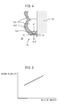
FIG. 3 is a partial enlarged cross-sectional view of a cathode. -
FIG. 4 is a schematic view which explains an electrochemical reaction at a cathode. -
FIG. 5 is a graph which shows an oxygen solubility of an ionomer. -
FIG. 6 is a graph which shows a change of an output voltage value of a cell for fuel cell in the prior art. -
FIG. 7 is a graph which shows a change of output voltage value of a cell for fuel cell of an embodiment according to the present invention. -
FIG. 8 is a time chart which explains control for restoration. -
FIG. 9 is a time chart which explains control for restoration. -
FIG. 10 is a time chart which explains control for restoration. -
FIG. 11 is a flow chart which shows a routine for performing control for restoration. -
FIG. 12 is a flow chart which shows a routine for performing control for restoration. -
FIG. 13 is an overall view of a fuel cell system A of another embodiment according to the present invention. -
FIG. 14 is a time chart which explains control for restoration of another embodiment according to the present invention. -
FIG. 15 is a time chart which explains control for restoration of another embodiment according to the present invention. -
FIG. 16 is a time chart which explains control for restoration of another embodiment according to the present invention. -
FIG. 17 is a flow chart which shows a routine for performing control for restoration of another embodiment according to the present invention. -
FIG. 18 is a flow chart which shows a routine for performing control for restoration of another embodiment according to the present invention. -
FIG. 19 is a time chart which explains another embodiment of control for increasing an oxidizing gas amount. -
FIG. 20 is a graph which shows a relationship between an increased oxidizing gas amount QOFCI and an electrical resistance value RFC of a cell for fuel cell. -
FIG. 21 is a graph which shows a relationship between a holding time tFCI and an electrical resistance value RFC of a cell for fuel cell. -
FIG. 22 is a graph which shows a relationship between a number of times of increase NFCI and an electrical resistance value RFC of a cell for fuel cell. - Referring to
FIG. 1 , a fuel cell system A is provided with acell 1 for fuel cell. Thecell 1 has amembrane electrode assembly 2. As shown inFIG. 2 , themembrane electrode assembly 2 is provided with a membrane-like electrolyte 2e, ananode 2a which is formed at one side of theelectrolyte 2e, and acathode 2c which is formed at the other side of theelectrolyte 2e. Theanode 2a andcathode 2c, as shown inFIG. 1 , are electrically connected through an DC/AC converter 3 to for example anelectric motor 4 for driving a vehicle on one hand, and are electrically connected through an AC/AC converter 5 to anelectric accumulator 6 on the other hand. In the fuel cell system A which is shown inFIG. 1 , theelectric accumulator 6 is comprised of a battery. Further, as shown inFIG. 1 andFIG. 2 , inside thecell 1, afuel gas passage 10 for feeding fuel gas to theanode 2a and an oxidizinggas passage 20 which feeds oxidizing gas to thecathode 2c are formed. Inside thecell 1, further, thecell 1 is formed with acooling water passage 30 for feeding cooling water to thecell 1. - Note that, the fuel cell system A which is shown in
FIG. 1 is provided with a plurality ofcells 1. Thesecells 1 are stacked in series with each other to form a fuel cell stack. In this case, the above-mentionedfuel gas passages 10, oxidizinggas passages 20, andcooling water passages 30 are respectively connected with each other. - At an inlet of the
fuel gas passage 10, a fuelgas feed path 11 is connected. The fuelgas feed path 11 is connected to afuel gas source 12. In an embodiment according to the present invention, the fuel gas is comprised of hydrogen and thefuel gas source 12 is comprised of a hydrogen tank. Inside the fuelgas feed path 11, a fuelgas control valve 13 which controls an amount of fuel gas which flows through the inside of the fuelgas feed path 11 is arranged. On the other hand, at an outlet of thefuel gas passage 10, an anode off-gas passage 14 is connected. Inside the anode off-gas passage 14, an anode off-gas control valve 15 which controls an amount of anode off-gas which flows through the inside of the anode off-gas passage 14 is arranged. When the fuelgas control valve 13 is opened, fuel gas inside thefuel gas source 12 is fed through the fuelgas feed path 11 to the inside of thecell 1. At this time, a gas which flows out from thefuel gas passage 10, that is, an anode off-gas, flows to the inside of the anode off-gas passage 14. - Further, at an inlet of the oxidizing
gas passage 20, an oxidizinggas feed path 21 is connected. The oxidizinggas feed path 21 is connected to an oxidizinggas source 22. In the embodiment according to the present invention, the oxidizing gas is comprised of air and the oxidizinggas source 22 is comprised of the atmosphere. Inside the oxidizinggas feed path 21, an oxidizing gas feeder orcompressor 23 which pumps out the oxidizing gas is arranged. On the other hand, at an outlet of the oxidizinggas passage 20, a cathode off-gas passage 24 is connected. When thecompressor 23 is driven, the oxidizing gas inside the oxidizinggas source 22 is fed through the oxidizinggas feed path 21 to the oxidizinggas passage 20 inside thecell 1. At this time, a gas which flows out from the oxidizinggas passage 20, that is, a cathode off-gas, flows into the cathode off-gas passage 24. - In the embodiment which is shown in
FIG. 1 , thecell 1 is comprised of a cell for fuel cell of an opposite flow type. That is, the inlet of thefuel gas passage 10 and the outlet of the oxidizinggas passage 20 adjoin each other, the outlet of thefuel gas passage 10 and inlet of the oxidizinggas passage 20 adjoin each other, and therefore the fuel gas and oxidizing gas flow inside thecell 1 substantially in parallel and in reverse directions to each other. In another embodiment, thecell 1 is comprised of a cell for fuel cell of a concurrent flow type. That is, the inlet of thefuel gas passage 10 and the inlet of the oxidizinggas passage 20 adjoin each other, the outlet of thefuel gas passage 10 and the outlet of the oxidizinggas passage 20 adjoin each other, and therefore the fuel gas and oxidizing gas flow inside thecell 1 substantially in parallel and in the same direction as each other. In still another embodiment, thecell 1 is comprised of a cell for fuel cell of a perpendicular flow type. That is, the fuel gas and oxidizing gas flow inside thecell 1 substantially perpendicular to each other. - Further, referring to
FIG. 1 , at an inlet of the coolingwater passage 30, one end of a coolingwater feed path 31 is connected. At an outlet of the coolingwater feed path 31, the other end of the coolingwater feed path 31 is connected. Inside the coolingwater feed path 31, a coolingwater pump 32 for pumping out cooling water and aradiator 33 are arranged. The coolingwater feed path 31 upstream of theradiator 33 and the coolingwater feed path 31 between theradiator 33 and the coolingwater pump 32 are connected with each other by aradiator bypass passage 34. Further, a radiatorbypass control valve 35 which controls an amount of cooling water which flows through the inside of theradiator bypass passage 34 is provided. In the fuel cell system A which is shown inFIG. 1 , the radiatorbypass control valve 35 is comprised of a three-way valve and is arranged at an inlet of theradiator bypass passage 34. When the coolingwater pump 32 is driven, the cooling water which is discharged from the coolingwater pump 32 flows through the coolingwater feed path 31 to the coolingwater passage 30 in thecell 1, then passes through the coolingwater passage 30 to flow into the coolingwater feed path 31 and passes through theradiator 33 orradiator bypass passage 34 to be returned to the coolingwater pump 32. In this case, if an amount of the cooling water which is sent by the radiatorbypass control valve 35 to theradiator 33 is increased, a cooling water temperature is lowered and therefore a temperature of thecell 1 is lowered. Alternatively, if the amount of cooling water which is discharged from the coolingwater pump 32 is increased, the temperature of thecell 1 is lowered. In this way, the coolingwater feed path 31, coolingwater pump 32, and radiatorbypass control valve 35 act as a fuel cell temperature controller which controls the fuel cell temperature. - The
electronic control unit 50 is comprised of a digital computer which is provided with components which are connected with each other by abidirectional bus 51 such as a ROM (read only memory) 52, RAM (random access memory) 53, CPU (microprocessor) 54,input port 55, andoutput port 56. At the coolingwater feed path 31 which adjoins the coolingwater passage 30 in thecell 1, atemperature sensor 40 which detects a temperature of the cooling water is attached. The cooling water temperature which is detected by thetemperature sensor 40 expresses a temperature of thecell 1. Further, between theanode 2a andcathode 2c of thecell 1, avoltmeter 41 andelectrical resistance meter 42 which respectively detect an output voltage value of thecell 1 and electrical resistance value are provided. The output signals of thetemperature sensor 40,voltmeter 41, andelectrical resistance meter 42 are input throughcorresponding AD converters 57 to theinput port 55. On the other hand, theoutput port 56 is connected throughcorresponding drive circuits 58 through the fuelgas control valve 13, anode off-gas control valve 15,compressor 23, coolingwater pump 32, and radiatorbypass control valve 35. -
FIG. 3 shows a partially enlarged cross-sectional view of thecathode 2c. As shown inFIG. 3 , thecathode 2c includes a conductive material 2c1 in a form of particulates, an ionomer 2c2 which covers the conductive material 2c1, and a catalyst 2c3 in a form of particulates which is carried on the conductive material 2c1. Further, in the example which is shown inFIG. 3 , the conductive material 2c1 is comprised of carbon, the ionomer 2c2 is comprised of an electrolyte which is the same as or similar to theelectrolyte 2e, and the catalyst 2c3 is comprised of platinum. Note that, inFIG. 3 , 2c4 shows a clearance which is formed at thecathode 2c. - Now then, if fuel gas is fed into the
fuel gas passage 10 in thecell 1 and oxidizing gas is fed into the oxidizinggas passage 20, electrical energy is generated in thecell 1. This generated electrical energy is sent to theelectric motor 4 for driving the vehicle. Due to this, themotor 4 is driven. Alternatively, the generated electrical energy is sent to theelectric accumulator 6 where it is stored. - In this case, in the
cathode 2c, the following electrochemical reaction (1) is performed:
O2+4H++4e-→2H2O (1)
- That is, as shown in
FIG. 4 , the hydrogen ions H+ pass through theelectrolyte 2e and reach thecathode 2c, in particular a surface of the catalyst 2c3. Further, the oxygen O2 passes through the ionomer 2c2 and reaches the surface of the catalyst 2c3. Alternatively, it passes through the clearance which is formed at thecathode 2c (FIG. 3 ) and reaches the catalyst 2c3. Furthermore, the electrons e- are conducted through the conductive material 2c1 and reach the surface of the catalyst 2c3. As a result, the above-mentioned electrochemical reaction (1) occurs and moisture is generated. - In this regard, if the temperature of the
cell 1 becomes higher, moistness of thecell 1, in particular themembrane electrode assembly 2 falls due to an increase of an amount of evaporated moisture. If the moistness of thecell 1 falls, a power generation quantity or efficiency of thecell 1 is liable to become lower, as has been known in the past. The present inventors earnestly investigated the mechanism of this phenomenon and learned that an oxygen permeability of the ionomer 2c2 is involved in the drop in the power generation quantity of thecell 1. This will be explained while referring toFIG. 5 . -
FIG. 5 shows results of experiments which show a relationship between a relative humidity (%) of the atmosphere around an ionomer and an oxygen solubility of the ionomer. This relative humidity expresses moistness of ionomer. As will be understood fromFIG. 5 , if the relative humidity falls, the oxygen solubility of the ionomer falls. On the other hand, the oxygen permeability of the ionomer is expressed by a product of the oxygen solubility of the ionomer and an oxygen diffusion coefficient of the ionomer. Therefore, if the moistness of the ionomer falls, the oxygen permeability of the ionomer falls. - If the oxygen permeability of the ionomer falls, an amount of oxidizing gas or an amount of oxygen which reaches the
cathode 2c decreases. As a result, it becomes harder for the above-mentioned electrochemical reaction (1) to proceed and therefore the power generation quantity of thecell 1 is decreased. This is the mechanism behind the decrease in the power generation quantity of the cell which occurs when the moistness of thecell 1 falls. - In accordance with the above, if making the amount of oxidizing gas or the amount of oxygen which passes through the ionomer 2c2 increase or be restored when the moistness of the
cell 1 becomes low, the power generation quantity of thecell 1 can be increased or restored. In order to make the amount of oxidizing gas which passes through the ionomer 2c2 increase, it is sufficient to make an amount of oxidizing gas around thecathode 2c increase. For that, it is sufficient to make an amount of oxidizing gas which is sent to thecell 1 or oxidizinggas passage 20 increase. - On the other hand, moistness of the
cell 1 is represented by the electrical resistance value of thecell 1. That is, as the moistness of thecell 1 becomes lower, the electrical resistance value of thecell 1 becomes larger. - On the other hand, in normal power generation control, the fuel cell system A is controlled to make an output current value of the
cell 1 equal to a target current value which is determined based on a target power generation quantity of thecell 1. Therefore, considering the fact that the power generation quantity of thecell 1 is represented by a product of an output current value and an output voltage value of thecell 1, it can be the that a power generation quantity of thecell 1 when the output voltage value is low is decreased compared with that when the output voltage value is high, under the same output current. - Therefore, in the embodiment according to the present invention, when the output voltage value of the
cell 1 is lower than a predetermined threshold voltage value and the electrical resistance value of thecell 1 is higher than a predetermined threshold resistance value, the oxidizinggas feeder 23 is controlled to perform control for increasing an oxidizing gas amount which increases an amount of oxidizing gas sent to thecell 1. As a result, the amount or concentration of oxidizing gas in the oxidizinggas passage 20 is increased and thereby the amount of oxidizing gas which passes through the ionomer and reaches thecathode 2c is increased. Therefore, the power generation quantity of thecell 1 is quickly increased. - The power generation quantity of the
cell 1 being increased means that an amount of moisture which is produced by the above-mentioned electrochemical reaction (1) is increased. As a result, moistness of thecell 1 also rises or is restored. If the moistness of thecell 1 raises, the oxygen permeability of the ionomer rises, therefore the power generation quantity of thecell 1 is further increased. - In this regard, another prior art is known where if the moistness of the
cell 1 becomes lower, control for decreasing an oxidizing gas amount which decreases an amount of oxidizing gas sent to thecell 1 is performed. In this prior art, an amount of moisture which the cathode off-gas carries off from thecell 1 is decreased, so the moistness of thecell 1 raises and therefore the power generation quantity of thecell 1 is increased or restored. In this regard, if the amount of oxidizing gas is decreased, the amount of oxidizing gas around thecathode 2c is decreased. Therefore, the amount of oxidizing gas which passes through the ionomer and reaches thecathode 2c is further decreased. For this reason, the power generation quantity of thecell 1 is further reduced at the beginning of control for decreasing the oxidizing gas amount and then is increased. That is, in control for decreasing the oxidizing gas amount, a long time is required for making the power generation quantity of thecell 1 increase. - On the other hand, still another prior art is known where if moistness of the
cell 1 becomes lower, control for lowering a fuel cell temperature which lowers a temperature of thecell 1 is performed. In the still another prior art, condensation of water vapor is promoted around thecathode 2c of thecell 1, so the moistness of thecell 1 raises and therefore the power generation quantity of thecell 1 is increased or restored. In this regard, if a cooling water temperature of thecell 1 is lowered to perform the control for lowering the fuel cell temperature, a long time is required to lower the temperature of thecell 1. Alternatively, if the temperature of thecell 1 is lowered, it becomes harder for the above-mentioned electrochemical reaction (1) to proceed. Whatever the case, a long time is required for increasing or restoring the power generation quantity of thecell 1. -
FIG. 6 shows results of experiments which show an output voltage value VFC of thecell 1 when the above-mentioned control for lowering a fuel cell temperature is performed. InFIG. 6 , ta1 shows a time when the output voltage value VFC of thecell 1 becomes lower than a predetermined threshold voltage value VFCTH and the electrical resistance value of thecell 1 becomes higher than a predetermined threshold resistance value. As will be understood fromFIG. 6 , the output voltage value VFC of thecell 1 continues to fall for a while even after the control for lowering the fuel cell temperature is started, and starts to rise after a while. That is, in this case, a long time is required for increasing or restoring the power generation quantity of thecell 1. - As opposed to this,
FIG. 7 shows results of experiments which show an output voltage value VFC of thecell 1 when control for increasing an oxidizing gas amount is performed. InFIG. 7 , tb1 shows a time when the output voltage value VFC of thecell 1 becomes lower than a predetermined threshold voltage value VFCTH and the electrical resistance value of thecell 1 becomes higher than a predetermined threshold resistance value. As will be understood fromFIG. 7 , if control for increasing the oxidizing gas amount is started, the output voltage value VFC of thecell 1 immediately rises, therefore is restored in a short time. - In actuality, according to experiments of the present inventors, the time required from when the output voltage value VFC becomes lower than the threshold voltage value VFCTH to when it is restored was about 2 minutes in the example of
FIG. 6 , but was about 1 second in the example ofFIG. 7 . - Next, referring to
FIG. 8 to FIG. 10 , the embodiment according to the present invention will be further explained. In the example which is shown inFIG. 8 , if, at the time tc1, an output voltage value VFC of thecell 1 becomes lower than a predetermined threshold voltage value VFCTH and an electrical resistance value RFC of thecell 1 becomes higher than a predetermined threshold resistance value RFCTH, the above-mentioned control for increasing the oxidizing gas amount is started. As a result, an oxidizing gas amount QOFC which is sent to thecell 1 is increased from a base oxidizing gas amount QOFCB to an increased oxidizing gas amount QOFCI and held there. Note that the base oxidizing gas amount QOFCB is an amount of oxidizing gas at the time of normal control where control for increasing the oxidizing gas amount is not performed and is determined in accordance with, for example, a target power generation quantity of thecell 1. - Next, if, at the time tc2, the output voltage value VFC of the
cell 1 becomes equal to or larger than the threshold voltage value VFCTH, that is, if the output voltage value VFC of thecell 1 is restored, the control for increasing the oxidizing gas amount is stopped. As a result, the oxidizing gas amount QOFC which is sent to thecell 1 is returned to the base oxidizing gas amount QOFCB. Note that, in the example which is shown inFIG. 8 , at the time tc2, the electrical resistance value RFC of thecell 1 has been lower than the threshold resistance value RFCTH and therefore is restored. That is, in this way, control for increasing the oxidizing gas amount is temporarily performed whereby the output voltage value VFC and electrical resistance value RFC of thecell 1 are restored. - In the example which is shown in
FIG. 9 , if, at the time td1, the output voltage value VFC of thecell 1 becomes lower than the threshold voltage value VFCTH and the electrical resistance value RFC of thecell 1 becomes higher than the threshold resistance value RFCTH, the above-mentioned control for increasing the oxidizing gas amount is started. Next, if, at the time td2, the electrical resistance value RFC becomes higher than a predetermined upper limit resistance value RFC1, the control for increasing the oxidizing gas amount is stopped. As a result, the oxidizing gas amount QOFC which is sent to thecell 1 is returned to the base oxidizing gas amount QOFCB. Further, at the time td2, control for lowering the fuel cell temperature which lowers the temperature of thecell 1 is started. As a result, the temperature TFC of thecell 1 falls from a base fuel cell temperature TFCB to a lowered fuel cell temperature TFCBL and is held there. Note that the base fuel cell temperature TFCB is a fuel cell temperature at the time of normal control where the control for lowering the fuel cell temperature is not performed and is controlled so as not to exceed, for example, a certain value. Further, the control for lowering the fuel cell temperature is performed using one or both of lowering the temperature of the cooling water and increasing the amount of cooling water. - If control for increasing the oxidizing gas amount is performed, the amount of moisture which the cathode off-gas carries off from the
cell 1 is liable to increase and the electrical resistance value RFC of thecell 1 is liable to become excessively higher. Therefore, in the example which is shown inFIG. 9 , if the electrical resistance value RFC becomes higher than the upper limit resistance value RFC1 during control for increasing the oxidizing gas amount, the control for increasing the oxidizing gas amount is stopped. As a result, the electrical resistance value RFC can be prevented from becoming excessively high. On the other hand, it is still necessary to restore the output voltage value VFC. Therefore, in the example which is shown inFIG. 9 , if control for increasing the oxidizing gas amount is stopped due to the electrical resistance value RFC of thecell 1 becoming higher than the upper limit resistance value RFC1, the control for lowering the fuel cell temperature is performed. As a result, the output voltage value VFC gradually rises and the electrical resistance value RFC gradually falls. - Next, if, at the time td3, the output voltage value VFC of the
cell 1 is equal to or larger than the threshold voltage value VFCTH and the electrical resistance value RFC of thecell 1 is equal to or smaller than the threshold resistance value RFCTH, that is, the output voltage value VFC and electrical resistance value RFC of thecell 1 are both restored, the control for lowering the fuel cell temperature is stopped. As a result, the temperature of thecell 1 is returned to the base fuel cell temperature TFCB. - In the example which is shown in
FIG. 10 , if, at the time te1, the output voltage value VFC of thecell 1 becomes lower than the threshold voltage value VFCTH and the electrical resistance value RFC of thecell 1 becomes higher than the threshold resistance value RFCTH, the above-mentioned control for increasing the oxidizing gas amount is started. Next, if, at the time te2, the electrical resistance value RFC becomes higher than the upper limit resistance value RFC1, control for increasing the oxidizing gas amount is stopped and control for lowering the fuel cell temperature is started. - Next, if, at the time te3, the output voltage value VFC of the
cell 1 is lower than the threshold voltage value VFCTH while the electrical resistance value RFC of thecell 1 becomes equal to or smaller than the threshold resistance value RFCTH, that is, while the electrical resistance value RFC is restored, different control for making the output voltage value of thecell 1 rise is started. That is, in this case, it is considered that a reason different from the drop in moistness of thecell 1, for example, flooding, causes the output voltage value VFC of thecell 1 to fall. Therefore, in the example which is shown inFIG. 10 , different control for eliminating flooding is performed. - Next, if, at the time te4, the output voltage value VFC of the
cell 1 becomes equal to or larger than the threshold voltage value VFCTH, that is, if the output voltage value VFC is restored, the above-mentioned different control is stopped. - Note that, in the examples which are shown in
FIG. 8 to FIG. 10 , the electrical resistance value RFC of thecell 1 becomes higher than the threshold resistance value RFCTH and then the output voltage value VFC of thecell 1 becomes lower than the threshold voltage value VFCTH. In another example, the output voltage value VFC becomes lower than the threshold voltage value VFCTH and then the electrical resistance value RFC becomes higher than the threshold resistance value RFCTH. - The output voltage value of the
cell 1 and electrical resistance value depend on the target current value or output current value of thecell 1 and the temperature of thecell 1. In the embodiment according to the present invention, the threshold voltage value VFCTH and the threshold resistance value RFCTH are determined in advance as functions of, for example, the target current value of thecell 1 and the temperature of thecell 1 and are stored in the form of maps in theROM 52. In this regard, the output voltage value and electrical resistance value of thecell 1 can vary in accordance with the extent of aging of thecell 1. Therefore, in the other embodiment according to the present invention, the threshold voltage value VFCTH and the threshold resistance value RFCTH are corrected by the extent of aging of thecell 1. -
FIG. 11 andFIG. 12 show a routine for performing control for restoration of the above-mentioned embodiment according to the present invention. This routine is performed by interruption every certain time. Referring toFIG. 11 andFIG. 12 , atstep 100, it is judged if the output voltage value VFC of thecell 1 is lower than the threshold voltage value VFCTH. If VFC≥VFCTH, the processing cycle is ended. If VFC<VFCTH, next the routine proceeds to step 101 where it is judged if the electrical resistance value RFC of thecell 1 is higher than the threshold resistance value RFCTH. If RFC>RFCTH, next the routine proceeds to step 102 where control for increasing the oxidizing gas amount is started. At thenext step 103, it is judged if the output voltage value VFC of thecell 1 is equal to or larger than the threshold voltage value VFCTH. If VFC≥VFCTH, that is, if the output voltage value VFC is restored, next the routine proceeds to step 104 where control for increasing the oxidizing gas amount is stopped. Next, the processing cycle is ended. As opposed to this, if VFC<VFCTH, that is, if the output voltage value VFC has not yet been restored, the routine proceeds to step 105 where it is judged if the electrical resistance value RFC of thecell 1 is higher than the upper limit resistance value RFC1. If RFC≤RFC1, the routine returns to step 102 where control for increasing the oxidizing gas amount is continued. If RFC>RFC1, next, the routine proceeds to step 106 where control for increasing the oxidizing gas amount is stopped. Next, the routine proceeds to step 107. - At
step 107, the control for lowering the fuel cell temperature is started. At thenext step 108, it is judged if the electrical resistance value RFC of thecell 1 is equal to or smaller than a threshold resistance value RFCTH. If RFC>RFCTH, that is, if the electrical resistance value RFC has not yet been restored, the routine returns to step 107 where the control for lowering the fuel cell temperature is continued. If RFC≤RFCTH, that is, if the electrical resistance value RFC is restored, next the routine proceeds to step 109 where the control for lowering the fuel cell temperature is stopped. At thenext step 110, it is judged if the output voltage value VFC of thecell 1 is equal to or larger than the threshold voltage value VFCTH. If VFC≥VFCTH, the processing cycle is ended. Atstep 101 and step 110, if VFC<VFCTH, that is, if VFC<VFCTH and RFC≤RFCTH, the routine proceeds to step 111 where the above-mentioned different processing is performed. -
FIG. 13 shows another embodiment according to the present invention. In the other embodiment which is shown inFIG. 13 , a backpressure control valve 25 which controls a pressure inside the cathode off-gas passage 24, that is, a back pressure of thecell 1, is arranged inside the cathode off-gas passage 24. The backpressure control valve 25 is usually controlled so that the back pressure of thecell 1 is held constant. If an opening degree of the backpressure control valve 25 is made smaller, the back pressure of thecell 1 raises. - In the other embodiment according to the present invention, control for raising a back pressure which rises the back pressure of the
cell 1 is performed in addition to the above-mentioned control for increasing the oxidizing gas amount. In this case, the control for raising the back pressure is performed by making the opening degree of the backpressure control valve 25 smaller. If control for increasing the oxidizing gas amount and control for raising the back pressure are performed, the amount or concentration of the oxidizing gas at thecell 1, in particular around thecathode 2c, is further increased. As a result, it is possible to further quickly increase or restore the power generation quantity of thecell 1. - Next, referring to
FIG. 14 to FIG. 16 , the other embodiment according to the present invention will be further explained. In the example which is shown inFIG. 14 , if, at the time tf1, the output voltage value VFC of thecell 1 becomes lower than the predetermined threshold voltage value VFCTH and the electrical resistance value RFC of thecell 1 becomes higher than the predetermined threshold resistance value RFCTH, first, the above-mentioned control for increasing the oxidizing gas amount is started. As a result, the oxidizing gas amount QOFC which is sent to thefuel cell 1 is increased from the base oxidizing gas amount QOFCB. - Next, if, at the time tf2, the oxidizing gas amount QOFC is increased up to the increased oxidizing gas amount QOFCI, control for raising the back pressure is started. As a result, the back pressure PB of the
fuel cell 1 is raised from a base back pressure PBB to a raised back pressure PBR and held there. If control for raising the back pressure is performed before the oxidizing gas amount QOFC is increased, the amount of oxidizing gas around thecathode 2c of thefuel cell 1 conversely is liable to decrease. Therefore, in the example which is shown inFIG. 14 , control for raising the back pressure is started after the oxidizing gas amount QOFC is increased. Note that the base back pressure PBB is a back pressure at the time of normal control where control for raising the back pressure is not performed and is determined in accordance with an amount of oxidizing gas from thecompressor 23. - Next, if, at the time tf3, the output voltage value VFC of the
fuel cell 1 becomes equal to or larger than the threshold voltage value VFCTH, that is, if the output voltage value VFC of thefuel cell 1 is restored, the control for increasing the oxidizing gas amount and the control for raising the back pressure are stopped. As a result, the oxidizing gas amount QOFC which is sent to thefuel cell 1 is returned to the base oxidizing gas amount QOFCB and the back pressure PB of thefuel cell 1 is returned to the base back pressure PBB. Note that, in the example which is shown inFIG. 14 , at the time tf3, the electrical resistance value RFC of thefuel cell 1 is lower than the threshold resistance value RFCTH and therefore is restored. - In the example which is shown in
FIG. 15 , if, at the time tg1, the output voltage value VFC of thefuel cell 1 becomes lower than the threshold voltage value VFCTH and the electrical resistance value RFC of thefuel cell 1 becomes higher than the threshold resistance value RFCTH, the above-mentioned control for increasing the oxidizing gas amount is started. Next, if, at the time tg2, the oxidizing gas amount QOFC is increased up to the increased oxidizing gas amount QOFCI, control for raising the back pressure is started. Next, if, at the time tg3, the electrical resistance value RFC becomes higher than the predetermined upper limit resistance value RFC1, control for increasing the oxidizing gas amount and control for raising the back pressure are stopped. As a result, the oxidizing gas amount QOFC which is sent to thefuel cell 1 is returned to the base oxidizing gas amount QOFCB, and the back pressure PB of thefuel cell 1 is returned to the base back pressure PBB. Further, at the time tg3, the control for lowering the fuel cell temperature is started. As a result, the temperature TFC of thefuel cell 1 is lowered from the base fuel cell temperature TFCB to the lowered fuel cell temperature TFCBL and held there. As a result, the output voltage value VFC gradually rises and the electrical resistance value RFC gradually falls. - Next, if, at the time tg4, the output voltage value VFC of the
fuel cell 1 becomes equal to or larger than the threshold voltage value VFCTH and the electrical resistance value RFC of thefuel cell 1 becomes equal to or smaller than the threshold resistance value RFCTH, that is, if the output voltage value VFC of thefuel cell 1 and electrical resistance value RFC are both restored, the control for lowering the fuel cell temperature is stopped. As a result, the temperature of thefuel cell 1 is returned to the base fuel cell temperature TFCB. - In the example which is shown in
FIG. 16 , if, at the time th1, the output voltage value VFC of thefuel cell 1 becomes lower than the threshold voltage value VFCTH and the electrical resistance value RFC of thefuel cell 1 becomes higher than the threshold resistance value RFCTH, the above-mentioned control for increasing the oxidizing gas amount is started. Next, if, at the time th2, the oxidizing gas amount QOFC is increased up to the increased oxidizing gas amount QOFCI, control for raising the back pressure is started. Next, if, at the time th3, the electrical resistance value RFC becomes higher than the upper limit resistance value RFC1, control for increasing the oxidizing gas amount and control for raising the back pressure are stopped and control for lowering the fuel cell temperature is started. - Next, if, at the time th4, the output voltage value VFC of the
fuel cell 1 is lower than the threshold voltage value VFCTH while the electrical resistance value RFC of thefuel cell 1 becomes equal to or smaller than the threshold resistance value RFCTH, that is, while the electrical resistance value RFC is restored, the above-mentioned different control, such as different control for eliminating flooding, is performed. - Next, if, at the time th5, the output voltage value VFC of the
fuel cell 1 becomes equal to or larger than the threshold voltage value VFCTH, that is, if the output voltage value VFC is restored, the above-mentioned different control is stopped. -
FIG. 17 andFIG. 18 show a routine for performing control for restoration of the above-mentioned other embodiment according to the present invention. This routine is performed by interruption every certain time. Referring toFIG. 17 andFIG. 18 , atstep 100, it is judged if the output voltage value VFC of thefuel cell 1 is lower than the threshold voltage value VFCTH. If VFC≥VFCTH, the processing cycle is ended. If VFC<VFCTH, next the routine proceeds to step 101 where it is judged if the electrical resistance value RFC of thefuel cell 1 is higher than the threshold resistance value RFCTH. If RFC>RFCTH, next the routine proceeds to step 102 where control for increasing the oxidizing gas amount is started. At thenext step 102a, the oxidizing gas amount QOFC is increased up to the increased oxidizing gas amount QOFCI, then control for raising the back pressure is started. At thenext step 103, it is judged if the output voltage value VFC of thefuel cell 1 is equal to or larger than the threshold voltage value VFCTH. If VFC≥VFCTH, that is, if the output voltage value VFC is restored, next the routine proceeds to step 104a where control for increasing the oxidizing gas amount and control for raising the back pressure are stopped. Next, the processing cycle is ended. As opposed to this, if VFC<VFCTH, that is, if the output voltage value VFC has still not been restored, the routine proceeds to step 105 where it is judged if the electrical resistance value RFC of thefuel cell 1 is higher than the upper limit resistance value RFC1. If RFC≤RFC1, the routine returns to step 102 where control for increasing the oxidizing gas amount and control for raising the back pressure are continued. If RFC>RFC1, next the routine proceeds to step 106a where control for increasing the oxidizing gas amount and control for raising the back pressure are stopped. Next, the routine proceeds to step 107. - At
step 107, the control for lowering the fuel cell temperature is started. At thenext step 108, it is judged if the electrical resistance value RFC of thefuel cell 1 is equal to or smaller than the threshold resistance value RFCTH. If RFC>RFCTH, that is, if the electrical resistance value RFC has still not been restored, the routine returns to step 107 where the control for lowering the fuel cell temperature is continued. If RFC≤RFCTH, that is, if the electrical resistance value RFC is restored, next the routine proceeds to step 109 where the control for lowering the fuel cell temperature is stopped. At thenext step 110, it is judged if the output voltage value VFC of thefuel cell 1 is equal to or larger than the threshold voltage value VFCTH. If VFC≥VFCTH, the processing cycle is ended. If, atstep 101 and step 110, VFC<VFCTH, that is, if VFC<VFCTH and RFC≤RFCTH, the routine proceeds to step 111 where the above-mentioned different processing is performed. - The rest of the configuration and operation of the other embodiment according to the present invention are similar to the configuration and operation of the above-mentioned embodiment according to the present invention, so explanations will be omitted.
- In the embodiments of the present invention explained up to here, in the control for increasing the oxidizing gas amount, the oxidizing gas amount QOFC which is sent to the
fuel cell 1 is continuously increased. As opposed to this, in the embodiment which is shown inFIG. 19 , the oxidizing gas amount QOFC is intermittently increased. That is, the oxidizing gas amount QOFC is increased from the base oxidizing gas amount QOFCB to the increased oxidizing gas amount QOFCI and held there, and is then returned to the base oxidizing gas amount QOFCB if a holding time tFCI elapses. The action of increasing the oxidizing gas amount is performed for the number of times of increase NFCI. - Here, as shown in
FIG. 20 , if the increased oxidizing gas amount QOFCI becomes greater than an upper limit gas amount QOFCI1, the electrical resistance value RFC of thefuel cell 1 will become higher than the upper limit resistance value RFC1. Therefore, the increased oxidizing gas amount QOFCI is set to be equal to or smaller than the upper limit amount QOFCI1. - Further, as shown in
FIG. 21 , if the holding time tFCI becomes longer than an upper limit time tFCI1, the electrical resistance value RFC of thefuel cell 1 becomes higher than the upper limit resistance value RFC1. Therefore, the holding time tFCI is set to be equal to or shorter than the upper limit time tFCI1. - Furthermore, as shown in
FIG. 22 , if the number of times of increase NFCI becomes greater than an upper limit value NFCI1, the electrical resistance value RFC of thefuel cell 1 becomes higher than the upper limit resistance value RFC1. Therefore, the number of times of increase NFCI is set to be equal to or smaller than the upper limit value NFCI1. - On the other hand, in the embodiments explained up to here, if the electrical resistance value RFC of the fuel cell becomes higher than the upper limit resistance value RFC1 during control for increasing the oxidizing gas amount, the oxidizing gas amount QOFC which is sent to the
fuel cell 1 is returned to the base oxidizing gas amount QOFCB. In another embodiment, if the electrical resistance value RFC of the fuel cell becomes higher than the upper limit resistance value RFC1 during control for increasing the oxidizing gas amount, control for decreasing an oxidizing gas is performed to make the oxidizing gas amount QOFC smaller than the base oxidizing gas amount QOFCB. If control for decreasing the oxidizing gas is performed, the amount of moisture which the cathode off-gas carries off from thefuel cell 1 is decreased, so the moistness of thefuel cell 1 is raised. - Next, another embodiment of the fuel cell system A will be explained. The other embodiment of the fuel cell system A is further provided with a recirculation passage which connects the anode off-
gas passage 14 upstream of the anode off-gas control valve 15 and the fuelgas feed path 11 downstream of the fuelgas control valve 13 with each other, and an anode off-gas pump which is arranged in the recirculation passage. Part or all of the anode off-gas in the anode off-gas passage 14 is returned by the anode off-gas pump through the recirculation passage to the fuelgas feed path 11. - The anode off-gas contains moisture. Therefore, this moisture is returned to the inside of the
fuel cell 1 together with the gas by returning the anode off-gas in the anode off-gas passage 14 to the fuelgas feed path 11 as in the other embodiment of the fuel cell system A. As a result, the moistness of thefuel cell 1 does not easily fall. - As opposed to this, in the fuel cell systems A which are shown in
FIG. 1 andFIG. 13 , the anode off-gas passage 14 and the fuelgas feed path 11 are not connected with each other. Therefore, the anode off-gas flows through the anode off-gas passage 14 without being returned from the anode off-gas passage 14 to the fuelgas feed path 11. This enables the configuration of the fuel cell system A to simplify and enables the cost lower. In this regard, in this case, the moisture which is contained in the anode off-gas is not returned to thefuel cell 1. For this reason, in the fuel cell systems A which are shown inFIG. 1 andFIG. 13 , the moistness of thefuel cell 1 easily falls. Therefore, in the embodiments according to the present invention, control for increasing the oxidizing gas amount is performed if the output voltage value of thefuel cell 1 falls and the moistness of thefuel cell 1 falls. Of course, the present invention can be applied to the above-mentioned other embodiment of the fuel cell system A as well. - The present application claims the benefit of Japanese Patent Application No.
2013-266968 -
- 1. cell for fuel cell
- 2. membrane electrode assembly
- 2c. cathode
- 2c1. conductive material
- 2c2. ionomer
- 20. oxidizing gas passage
- 21. oxidizing gas feed path
- 23. compressor
- 41. voltmeter
- 42. electrical resistance meter
Claims (9)
- A fuel cell system comprising: a cell for fuel cell, the cell having a membrane electrode assembly provided with an electrolyte and a cathode and anode respectively arranged at two sides of the electrolyte and an oxidizing gas passage configured to feed an oxidizing gas to the cathode; an oxidizing gas feed path connected to an inlet of the oxidizing gas passage; and an oxidizing gas feeder arranged in the oxidizing gas feed path and configured to feed oxidizing gas to the cathode, wherein the cathode includes a conductive material, catalyst, and ionomer which covers the conductive material and catalyst, and wherein, if an output voltage value of the cell is lower than a predetermined threshold voltage value and an electrical resistance value of the cell is higher than a predetermined threshold resistance value, the oxidizing gas feeder is controlled to perform control for increasing an oxidizing gas amount which increases an amount of oxidizing gas sent to the cell.
- The fuel cell system according to claim 1, wherein the control for increasing the oxidizing gas amount is stopped if the output voltage value of the cell becomes higher than the threshold voltage value during the control for increasing the oxidizing gas amount.
- The fuel cell system according to claim 1 or 2, wherein the control for increasing the oxidizing gas amount is stopped if the electrical resistance value of the cell becomes higher than a predetermined upper limit resistance value during the control for increasing the oxidizing gas amount.
- The fuel cell system according to claim 3, further comprising a fuel cell temperature controller configured to control a temperature of the cell, wherein control for lowering a fuel cell temperature which lowers the temperature of the cell is performed if the control for increasing the oxidizing gas amount is stopped due to the electrical resistance value of the cell becoming higher than the upper limit resistance value.
- The fuel cell system according to claim 4, wherein the control for lowering the fuel cell temperature is stopped if the electrical resistance value of the cell becomes lower than the threshold resistance value during the control for lowering the fuel cell temperature.
- The fuel cell system according to any one of claims 1 to 5, further comprising a cathode off-gas passage connected to an outlet of the oxidizing gas passage of the cell and a back pressure control valve arranged in the cathode off-gas passage and configured to control a back pressure of the cell, wherein the control for increasing the oxidizing gas amount is performed and the back pressure control valve is controlled to perform control for raising a back pressure which rises the back pressure of the cell if the output voltage value of the cell is lower than the predetermined threshold voltage value and the electrical resistance value of the cell is higher than the predetermined threshold resistance value.
- The fuel cell system according to claim 6, wherein, when performing the control for increasing the oxidizing gas amount and the control for raising the back pressure, first the control for increasing the oxidizing gas amount is performed to increase and maintain an amount of the oxidizing gas up to a predetermined target amount, and then the control for raising the back pressure is performed.
- The fuel cell system according to any one of claims 1 to 7, wherein the amount of oxidizing gas is intermittently increased in the control for increasing the oxidizing gas amount.
- The fuel cell system according to any one of claims 1 to 8, wherein the cell further has a fuel gas passage configured to feed fuel gas to the anode, wherein the fuel cell system further comprises a fuel gas feed path connected to an inlet of the fuel gas passage and an anode off-gas passage connected to an outlet of the fuel gas passage, and wherein an anode off-gas flows through the anode off-gas passage without being returned from the anode off-gas passage to the fuel gas feed path.
Applications Claiming Priority (2)
| Application Number | Priority Date | Filing Date | Title |
|---|---|---|---|
| JP2013266968A JP6003878B2 (en) | 2013-12-25 | 2013-12-25 | Fuel cell system |
| PCT/JP2014/079204 WO2015098291A1 (en) | 2013-12-25 | 2014-11-04 | Fuel battery system |
Publications (3)
| Publication Number | Publication Date |
|---|---|
| EP3089253A4 EP3089253A4 (en) | 2016-11-02 |
| EP3089253A1 true EP3089253A1 (en) | 2016-11-02 |
| EP3089253B1 EP3089253B1 (en) | 2018-04-18 |
Family
ID=53478169
Family Applications (1)
| Application Number | Title | Priority Date | Filing Date |
|---|---|---|---|
| EP14875461.7A Not-in-force EP3089253B1 (en) | 2013-12-25 | 2014-11-04 | Fuel cell system |
Country Status (7)
| Country | Link |
|---|---|
| US (1) | US10069159B2 (en) |
| EP (1) | EP3089253B1 (en) |
| JP (1) | JP6003878B2 (en) |
| KR (1) | KR101845144B1 (en) |
| CN (1) | CN105849957B (en) |
| CA (1) | CA2916455C (en) |
| WO (1) | WO2015098291A1 (en) |
Families Citing this family (1)
| Publication number | Priority date | Publication date | Assignee | Title |
|---|---|---|---|---|
| KR101631272B1 (en) * | 2015-08-27 | 2016-06-24 | 김건택 | Fuel cell system capable of producing high temperature warm water at high efficiency |
Family Cites Families (21)
| Publication number | Priority date | Publication date | Assignee | Title |
|---|---|---|---|---|
| JP3584511B2 (en) * | 1994-12-12 | 2004-11-04 | トヨタ自動車株式会社 | Operation control method of polymer electrolyte fuel cell |
| EP0949703A1 (en) * | 1996-12-27 | 1999-10-13 | Japan Storage Battery Co., Ltd. | Gas diffusion electrode, solid polymer electrolyte membrane, method of producing them, and solid polymer electrolyte type fuel cell using them |
| US6746793B1 (en) * | 1998-06-16 | 2004-06-08 | Matsushita Electric Industrial Co., Ltd. | Polymer electrolyte fuel cell |
| JP4200576B2 (en) * | 1999-02-23 | 2008-12-24 | トヨタ自動車株式会社 | Fuel cell system |
| JP3685039B2 (en) | 2000-10-31 | 2005-08-17 | 松下電器産業株式会社 | Polymer electrolyte fuel cell system |
| JP3687530B2 (en) | 2000-11-24 | 2005-08-24 | 日産自動車株式会社 | Fuel cell system and operation method thereof |
| JP2002231283A (en) | 2001-01-31 | 2002-08-16 | Fuji Electric Co Ltd | Solid polymer electrolyte fuel cell generating device and its operating method |
| JP2004220794A (en) | 2003-01-09 | 2004-08-05 | Nissan Motor Co Ltd | Control device of fuel cell |
| US7318971B2 (en) | 2003-02-14 | 2008-01-15 | Denso Corporation | Fuel cell system utilizing control of operating current to adjust moisture content within fuel cell |
| JP4608892B2 (en) * | 2003-02-14 | 2011-01-12 | 株式会社デンソー | Fuel cell system |
| JP4804447B2 (en) * | 2006-12-05 | 2011-11-02 | パナソニック株式会社 | ANTENNA DEVICE AND WIRELESS COMMUNICATION DEVICE |
| JP2008147102A (en) * | 2006-12-13 | 2008-06-26 | Toyota Motor Corp | Fuel cell system |
| JP2009016272A (en) * | 2007-07-06 | 2009-01-22 | Nissan Motor Co Ltd | Electrochemical cell system, operation method therefor, and fuel battery car equipped with the electrochemical cell system |
| JP4622005B2 (en) * | 2009-03-31 | 2011-02-02 | Toto株式会社 | Solid oxide fuel cell |
| WO2010131351A1 (en) | 2009-05-14 | 2010-11-18 | トヨタ自動車株式会社 | Fuel cell system |
| JP5324522B2 (en) | 2009-06-23 | 2013-10-23 | 本田技研工業株式会社 | Fuel cell system |
| JP5564315B2 (en) | 2010-04-06 | 2014-07-30 | 本田技研工業株式会社 | Fuel cell system |
| JP5691385B2 (en) * | 2010-10-22 | 2015-04-01 | トヨタ自動車株式会社 | Degradation judgment system for fuel cells |
| JP5585412B2 (en) * | 2010-11-19 | 2014-09-10 | 日産自動車株式会社 | Fuel cell system |
| JP2013105590A (en) * | 2011-11-11 | 2013-05-30 | Yazaki Corp | Connector |
| JP5812118B2 (en) * | 2012-01-10 | 2015-11-11 | 日産自動車株式会社 | Fuel cell system |
-
2013
- 2013-12-25 JP JP2013266968A patent/JP6003878B2/en active Active
-
2014
- 2014-11-04 KR KR1020157033900A patent/KR101845144B1/en active IP Right Grant
- 2014-11-04 EP EP14875461.7A patent/EP3089253B1/en not_active Not-in-force
- 2014-11-04 CN CN201480060496.XA patent/CN105849957B/en not_active Expired - Fee Related
- 2014-11-04 CA CA2916455A patent/CA2916455C/en active Active
- 2014-11-04 WO PCT/JP2014/079204 patent/WO2015098291A1/en active Application Filing
- 2014-11-04 US US15/107,656 patent/US10069159B2/en active Active
Also Published As
| Publication number | Publication date |
|---|---|
| CN105849957B (en) | 2019-03-26 |
| CA2916455A1 (en) | 2015-07-02 |
| WO2015098291A1 (en) | 2015-07-02 |
| KR20160008208A (en) | 2016-01-21 |
| CA2916455C (en) | 2018-08-21 |
| US20160315342A1 (en) | 2016-10-27 |
| EP3089253A4 (en) | 2016-11-02 |
| KR101845144B1 (en) | 2018-04-03 |
| EP3089253B1 (en) | 2018-04-18 |
| CN105849957A (en) | 2016-08-10 |
| JP2015122285A (en) | 2015-07-02 |
| JP6003878B2 (en) | 2016-10-05 |
| US10069159B2 (en) | 2018-09-04 |
Similar Documents
| Publication | Publication Date | Title |
|---|---|---|
| US9722261B2 (en) | Fuel cell system | |
| JP4379749B2 (en) | Fuel cell system | |
| EP2950376B1 (en) | Fuel cell system and fuel cell powered vehicle | |
| JP5136415B2 (en) | Fuel cell system | |
| JP2013232361A (en) | Fuel cell system | |
| US10290888B2 (en) | Method of operating fuel cell system with performance recovery control | |
| JP5454566B2 (en) | FUEL CELL SYSTEM, METHOD, PROGRAM, AND RECORDING MEDIUM | |
| CA2916455C (en) | Fuel cell system | |
| JP2013134866A (en) | Fuel cell system and fuel cell system control method | |
| US11158873B2 (en) | Control device for fuel cell system | |
| JP2016134258A (en) | Control device for fuel battery system | |
| JP2015122285A5 (en) | ||
| JP6958052B2 (en) | Fuel cell system | |
| JP2015170447A (en) | fuel cell system | |
| JP2016054056A (en) | Fuel cell system and control method for the same | |
| JP2012123914A (en) | Fuel battery system | |
| JP2008282616A (en) | Fuel cell system | |
| JP2016122548A (en) | Fuel battery system | |
| JP2020198231A (en) | Fuel cell system | |
| WO2014192649A1 (en) | Fuel-cell system and method for controlling fuel-cell system | |
| JP2015076246A (en) | Fuel cell system | |
| JP2016091697A (en) | Fuel cell system |
Legal Events
| Date | Code | Title | Description |
|---|---|---|---|
| PUAI | Public reference made under article 153(3) epc to a published international application that has entered the european phase |
Free format text: ORIGINAL CODE: 0009012 |
|
| 17P | Request for examination filed |
Effective date: 20150911 |
|
| A4 | Supplementary search report drawn up and despatched |
Effective date: 20160923 |
|
| AK | Designated contracting states |
Kind code of ref document: A1 Designated state(s): AL AT BE BG CH CY CZ DE DK EE ES FI FR GB GR HR HU IE IS IT LI LT LU LV MC MK MT NL NO PL PT RO RS SE SI SK SM TR |
|
| AX | Request for extension of the european patent |
Extension state: BA ME |
|
| DAX | Request for extension of the european patent (deleted) | ||
| STAA | Information on the status of an ep patent application or granted ep patent |
Free format text: STATUS: EXAMINATION IS IN PROGRESS |
|
| 17Q | First examination report despatched |
Effective date: 20170510 |
|
| REG | Reference to a national code |
Ref country code: DE Ref legal event code: R079 Ref document number: 602014024278 Country of ref document: DE Free format text: PREVIOUS MAIN CLASS: H01M0008040000 Ipc: H01M0008048580 |
|
| GRAP | Despatch of communication of intention to grant a patent |
Free format text: ORIGINAL CODE: EPIDOSNIGR1 |
|
| STAA | Information on the status of an ep patent application or granted ep patent |
Free format text: STATUS: GRANT OF PATENT IS INTENDED |
|
| RIC1 | Information provided on ipc code assigned before grant |
Ipc: H01M 8/04858 20160101AFI20171016BHEP Ipc: H01M 8/04746 20160101ALI20171016BHEP Ipc: H01M 8/1018 20160101ALI20171016BHEP Ipc: H01M 8/04537 20160101ALI20171016BHEP |
|
| INTG | Intention to grant announced |
Effective date: 20171110 |
|
| RIN1 | Information on inventor provided before grant (corrected) |
Inventor name: HASEGAWA, SHIGEKI Inventor name: YAMAUE, KEITA Inventor name: KAWAHARA, SHUYA |
|
| GRAS | Grant fee paid |
Free format text: ORIGINAL CODE: EPIDOSNIGR3 |
|
| GRAA | (expected) grant |
Free format text: ORIGINAL CODE: 0009210 |
|
| STAA | Information on the status of an ep patent application or granted ep patent |
Free format text: STATUS: THE PATENT HAS BEEN GRANTED |
|
| AK | Designated contracting states |
Kind code of ref document: B1 Designated state(s): AL AT BE BG CH CY CZ DE DK EE ES FI FR GB GR HR HU IE IS IT LI LT LU LV MC MK MT NL NO PL PT RO RS SE SI SK SM TR |
|
| REG | Reference to a national code |
Ref country code: GB Ref legal event code: FG4D |
|
| REG | Reference to a national code |
Ref country code: CH Ref legal event code: EP |
|
| REG | Reference to a national code |
Ref country code: AT Ref legal event code: REF Ref document number: 991381 Country of ref document: AT Kind code of ref document: T Effective date: 20180515 |
|
| REG | Reference to a national code |
Ref country code: IE Ref legal event code: FG4D |
|
| REG | Reference to a national code |
Ref country code: DE Ref legal event code: R096 Ref document number: 602014024278 Country of ref document: DE |
|
| REG | Reference to a national code |
Ref country code: NL Ref legal event code: MP Effective date: 20180418 |
|
| REG | Reference to a national code |
Ref country code: DE Ref legal event code: R084 Ref document number: 602014024278 Country of ref document: DE |
|
| REG | Reference to a national code |
Ref country code: LT Ref legal event code: MG4D |
|
| REG | Reference to a national code |
Ref country code: GB Ref legal event code: 746 Effective date: 20180829 |
|
| PG25 | Lapsed in a contracting state [announced via postgrant information from national office to epo] |
Ref country code: NL Free format text: LAPSE BECAUSE OF FAILURE TO SUBMIT A TRANSLATION OF THE DESCRIPTION OR TO PAY THE FEE WITHIN THE PRESCRIBED TIME-LIMIT Effective date: 20180418 |
|
| REG | Reference to a national code |
Ref country code: FR Ref legal event code: PLFP Year of fee payment: 5 |
|
| PG25 | Lapsed in a contracting state [announced via postgrant information from national office to epo] |
Ref country code: NO Free format text: LAPSE BECAUSE OF FAILURE TO SUBMIT A TRANSLATION OF THE DESCRIPTION OR TO PAY THE FEE WITHIN THE PRESCRIBED TIME-LIMIT Effective date: 20180718 Ref country code: AL Free format text: LAPSE BECAUSE OF FAILURE TO SUBMIT A TRANSLATION OF THE DESCRIPTION OR TO PAY THE FEE WITHIN THE PRESCRIBED TIME-LIMIT Effective date: 20180418 Ref country code: PL Free format text: LAPSE BECAUSE OF FAILURE TO SUBMIT A TRANSLATION OF THE DESCRIPTION OR TO PAY THE FEE WITHIN THE PRESCRIBED TIME-LIMIT Effective date: 20180418 Ref country code: FI Free format text: LAPSE BECAUSE OF FAILURE TO SUBMIT A TRANSLATION OF THE DESCRIPTION OR TO PAY THE FEE WITHIN THE PRESCRIBED TIME-LIMIT Effective date: 20180418 Ref country code: BG Free format text: LAPSE BECAUSE OF FAILURE TO SUBMIT A TRANSLATION OF THE DESCRIPTION OR TO PAY THE FEE WITHIN THE PRESCRIBED TIME-LIMIT Effective date: 20180718 Ref country code: LT Free format text: LAPSE BECAUSE OF FAILURE TO SUBMIT A TRANSLATION OF THE DESCRIPTION OR TO PAY THE FEE WITHIN THE PRESCRIBED TIME-LIMIT Effective date: 20180418 Ref country code: ES Free format text: LAPSE BECAUSE OF FAILURE TO SUBMIT A TRANSLATION OF THE DESCRIPTION OR TO PAY THE FEE WITHIN THE PRESCRIBED TIME-LIMIT Effective date: 20180418 Ref country code: SE Free format text: LAPSE BECAUSE OF FAILURE TO SUBMIT A TRANSLATION OF THE DESCRIPTION OR TO PAY THE FEE WITHIN THE PRESCRIBED TIME-LIMIT Effective date: 20180418 |
|
| PG25 | Lapsed in a contracting state [announced via postgrant information from national office to epo] |
Ref country code: RS Free format text: LAPSE BECAUSE OF FAILURE TO SUBMIT A TRANSLATION OF THE DESCRIPTION OR TO PAY THE FEE WITHIN THE PRESCRIBED TIME-LIMIT Effective date: 20180418 Ref country code: LV Free format text: LAPSE BECAUSE OF FAILURE TO SUBMIT A TRANSLATION OF THE DESCRIPTION OR TO PAY THE FEE WITHIN THE PRESCRIBED TIME-LIMIT Effective date: 20180418 Ref country code: GR Free format text: LAPSE BECAUSE OF FAILURE TO SUBMIT A TRANSLATION OF THE DESCRIPTION OR TO PAY THE FEE WITHIN THE PRESCRIBED TIME-LIMIT Effective date: 20180719 Ref country code: HR Free format text: LAPSE BECAUSE OF FAILURE TO SUBMIT A TRANSLATION OF THE DESCRIPTION OR TO PAY THE FEE WITHIN THE PRESCRIBED TIME-LIMIT Effective date: 20180418 |
|
| REG | Reference to a national code |
Ref country code: AT Ref legal event code: MK05 Ref document number: 991381 Country of ref document: AT Kind code of ref document: T Effective date: 20180418 |
|
| REG | Reference to a national code |
Ref country code: DE Ref legal event code: R097 Ref document number: 602014024278 Country of ref document: DE |
|
| PG25 | Lapsed in a contracting state [announced via postgrant information from national office to epo] |
Ref country code: DK Free format text: LAPSE BECAUSE OF FAILURE TO SUBMIT A TRANSLATION OF THE DESCRIPTION OR TO PAY THE FEE WITHIN THE PRESCRIBED TIME-LIMIT Effective date: 20180418 Ref country code: AT Free format text: LAPSE BECAUSE OF FAILURE TO SUBMIT A TRANSLATION OF THE DESCRIPTION OR TO PAY THE FEE WITHIN THE PRESCRIBED TIME-LIMIT Effective date: 20180418 Ref country code: SK Free format text: LAPSE BECAUSE OF FAILURE TO SUBMIT A TRANSLATION OF THE DESCRIPTION OR TO PAY THE FEE WITHIN THE PRESCRIBED TIME-LIMIT Effective date: 20180418 Ref country code: EE Free format text: LAPSE BECAUSE OF FAILURE TO SUBMIT A TRANSLATION OF THE DESCRIPTION OR TO PAY THE FEE WITHIN THE PRESCRIBED TIME-LIMIT Effective date: 20180418 Ref country code: RO Free format text: LAPSE BECAUSE OF FAILURE TO SUBMIT A TRANSLATION OF THE DESCRIPTION OR TO PAY THE FEE WITHIN THE PRESCRIBED TIME-LIMIT Effective date: 20180418 Ref country code: CZ Free format text: LAPSE BECAUSE OF FAILURE TO SUBMIT A TRANSLATION OF THE DESCRIPTION OR TO PAY THE FEE WITHIN THE PRESCRIBED TIME-LIMIT Effective date: 20180418 |
|
| PLBE | No opposition filed within time limit |
Free format text: ORIGINAL CODE: 0009261 |
|
| STAA | Information on the status of an ep patent application or granted ep patent |
Free format text: STATUS: NO OPPOSITION FILED WITHIN TIME LIMIT |
|
| PG25 | Lapsed in a contracting state [announced via postgrant information from national office to epo] |
Ref country code: SM Free format text: LAPSE BECAUSE OF FAILURE TO SUBMIT A TRANSLATION OF THE DESCRIPTION OR TO PAY THE FEE WITHIN THE PRESCRIBED TIME-LIMIT Effective date: 20180418 Ref country code: IT Free format text: LAPSE BECAUSE OF FAILURE TO SUBMIT A TRANSLATION OF THE DESCRIPTION OR TO PAY THE FEE WITHIN THE PRESCRIBED TIME-LIMIT Effective date: 20180418 |
|
| 26N | No opposition filed |
Effective date: 20190121 |
|
| PG25 | Lapsed in a contracting state [announced via postgrant information from national office to epo] |
Ref country code: SI Free format text: LAPSE BECAUSE OF FAILURE TO SUBMIT A TRANSLATION OF THE DESCRIPTION OR TO PAY THE FEE WITHIN THE PRESCRIBED TIME-LIMIT Effective date: 20180418 |
|
| REG | Reference to a national code |
Ref country code: CH Ref legal event code: PL |
|
| PG25 | Lapsed in a contracting state [announced via postgrant information from national office to epo] |
Ref country code: LU Free format text: LAPSE BECAUSE OF NON-PAYMENT OF DUE FEES Effective date: 20181104 Ref country code: MC Free format text: LAPSE BECAUSE OF FAILURE TO SUBMIT A TRANSLATION OF THE DESCRIPTION OR TO PAY THE FEE WITHIN THE PRESCRIBED TIME-LIMIT Effective date: 20180418 |
|
| REG | Reference to a national code |
Ref country code: BE Ref legal event code: MM Effective date: 20181130 |
|
| REG | Reference to a national code |
Ref country code: IE Ref legal event code: MM4A |
|
| PG25 | Lapsed in a contracting state [announced via postgrant information from national office to epo] |
Ref country code: CH Free format text: LAPSE BECAUSE OF NON-PAYMENT OF DUE FEES Effective date: 20181130 Ref country code: LI Free format text: LAPSE BECAUSE OF NON-PAYMENT OF DUE FEES Effective date: 20181130 |
|
| PG25 | Lapsed in a contracting state [announced via postgrant information from national office to epo] |
Ref country code: IE Free format text: LAPSE BECAUSE OF NON-PAYMENT OF DUE FEES Effective date: 20181104 |
|
| PG25 | Lapsed in a contracting state [announced via postgrant information from national office to epo] |
Ref country code: BE Free format text: LAPSE BECAUSE OF NON-PAYMENT OF DUE FEES Effective date: 20181130 |
|
| PG25 | Lapsed in a contracting state [announced via postgrant information from national office to epo] |
Ref country code: MT Free format text: LAPSE BECAUSE OF NON-PAYMENT OF DUE FEES Effective date: 20181104 |
|
| PG25 | Lapsed in a contracting state [announced via postgrant information from national office to epo] |
Ref country code: TR Free format text: LAPSE BECAUSE OF FAILURE TO SUBMIT A TRANSLATION OF THE DESCRIPTION OR TO PAY THE FEE WITHIN THE PRESCRIBED TIME-LIMIT Effective date: 20180418 |
|
| PG25 | Lapsed in a contracting state [announced via postgrant information from national office to epo] |
Ref country code: PT Free format text: LAPSE BECAUSE OF FAILURE TO SUBMIT A TRANSLATION OF THE DESCRIPTION OR TO PAY THE FEE WITHIN THE PRESCRIBED TIME-LIMIT Effective date: 20180418 |
|
| PG25 | Lapsed in a contracting state [announced via postgrant information from national office to epo] |
Ref country code: CY Free format text: LAPSE BECAUSE OF FAILURE TO SUBMIT A TRANSLATION OF THE DESCRIPTION OR TO PAY THE FEE WITHIN THE PRESCRIBED TIME-LIMIT Effective date: 20180418 Ref country code: HU Free format text: LAPSE BECAUSE OF FAILURE TO SUBMIT A TRANSLATION OF THE DESCRIPTION OR TO PAY THE FEE WITHIN THE PRESCRIBED TIME-LIMIT; INVALID AB INITIO Effective date: 20141104 Ref country code: MK Free format text: LAPSE BECAUSE OF NON-PAYMENT OF DUE FEES Effective date: 20180418 |
|
| PG25 | Lapsed in a contracting state [announced via postgrant information from national office to epo] |
Ref country code: IS Free format text: LAPSE BECAUSE OF FAILURE TO SUBMIT A TRANSLATION OF THE DESCRIPTION OR TO PAY THE FEE WITHIN THE PRESCRIBED TIME-LIMIT Effective date: 20180818 |
|
| PGFP | Annual fee paid to national office [announced via postgrant information from national office to epo] |
Ref country code: GB Payment date: 20210930 Year of fee payment: 8 |
|
| PGFP | Annual fee paid to national office [announced via postgrant information from national office to epo] |
Ref country code: DE Payment date: 20210929 Year of fee payment: 8 |
|
| PGFP | Annual fee paid to national office [announced via postgrant information from national office to epo] |
Ref country code: FR Payment date: 20211018 Year of fee payment: 8 |
|
| REG | Reference to a national code |
Ref country code: DE Ref legal event code: R119 Ref document number: 602014024278 Country of ref document: DE |
|
| GBPC | Gb: european patent ceased through non-payment of renewal fee |
Effective date: 20221104 |
|
| PG25 | Lapsed in a contracting state [announced via postgrant information from national office to epo] |
Ref country code: GB Free format text: LAPSE BECAUSE OF NON-PAYMENT OF DUE FEES Effective date: 20221104 Ref country code: DE Free format text: LAPSE BECAUSE OF NON-PAYMENT OF DUE FEES Effective date: 20230601 |
|
| PG25 | Lapsed in a contracting state [announced via postgrant information from national office to epo] |
Ref country code: FR Free format text: LAPSE BECAUSE OF NON-PAYMENT OF DUE FEES Effective date: 20221130 |