EP3088978A1 - Control apparatus for machine tool - Google Patents
Control apparatus for machine tool Download PDFInfo
- Publication number
- EP3088978A1 EP3088978A1 EP13900527.6A EP13900527A EP3088978A1 EP 3088978 A1 EP3088978 A1 EP 3088978A1 EP 13900527 A EP13900527 A EP 13900527A EP 3088978 A1 EP3088978 A1 EP 3088978A1
- Authority
- EP
- European Patent Office
- Prior art keywords
- tool
- machining program
- section
- program
- schedule
- Prior art date
- Legal status (The legal status is an assumption and is not a legal conclusion. Google has not performed a legal analysis and makes no representation as to the accuracy of the status listed.)
- Granted
Links
- 238000000034 method Methods 0.000 claims abstract description 37
- 238000005520 cutting process Methods 0.000 claims description 22
- 238000003754 machining Methods 0.000 description 20
- 230000003213 activating effect Effects 0.000 description 3
- 238000004364 calculation method Methods 0.000 description 1
- 238000010586 diagram Methods 0.000 description 1
- 230000000694 effects Effects 0.000 description 1
- 230000006870 function Effects 0.000 description 1
- 238000010079 rubber tapping Methods 0.000 description 1
- 238000004088 simulation Methods 0.000 description 1
Images


Classifications
-
- G—PHYSICS
- G05—CONTROLLING; REGULATING
- G05B—CONTROL OR REGULATING SYSTEMS IN GENERAL; FUNCTIONAL ELEMENTS OF SUCH SYSTEMS; MONITORING OR TESTING ARRANGEMENTS FOR SUCH SYSTEMS OR ELEMENTS
- G05B19/00—Programme-control systems
- G05B19/02—Programme-control systems electric
- G05B19/18—Numerical control [NC], i.e. automatically operating machines, in particular machine tools, e.g. in a manufacturing environment, so as to execute positioning, movement or co-ordinated operations by means of programme data in numerical form
- G05B19/4093—Numerical control [NC], i.e. automatically operating machines, in particular machine tools, e.g. in a manufacturing environment, so as to execute positioning, movement or co-ordinated operations by means of programme data in numerical form characterised by part programming, e.g. entry of geometrical information as taken from a technical drawing, combining this with machining and material information to obtain control information, named part programme, for the NC machine
- G05B19/40937—Numerical control [NC], i.e. automatically operating machines, in particular machine tools, e.g. in a manufacturing environment, so as to execute positioning, movement or co-ordinated operations by means of programme data in numerical form characterised by part programming, e.g. entry of geometrical information as taken from a technical drawing, combining this with machining and material information to obtain control information, named part programme, for the NC machine concerning programming of machining or material parameters, pocket machining
- G05B19/40938—Tool management
-
- G—PHYSICS
- G05—CONTROLLING; REGULATING
- G05B—CONTROL OR REGULATING SYSTEMS IN GENERAL; FUNCTIONAL ELEMENTS OF SUCH SYSTEMS; MONITORING OR TESTING ARRANGEMENTS FOR SUCH SYSTEMS OR ELEMENTS
- G05B19/00—Programme-control systems
- G05B19/02—Programme-control systems electric
- G05B19/18—Numerical control [NC], i.e. automatically operating machines, in particular machine tools, e.g. in a manufacturing environment, so as to execute positioning, movement or co-ordinated operations by means of programme data in numerical form
- G05B19/4093—Numerical control [NC], i.e. automatically operating machines, in particular machine tools, e.g. in a manufacturing environment, so as to execute positioning, movement or co-ordinated operations by means of programme data in numerical form characterised by part programming, e.g. entry of geometrical information as taken from a technical drawing, combining this with machining and material information to obtain control information, named part programme, for the NC machine
- G05B19/40937—Numerical control [NC], i.e. automatically operating machines, in particular machine tools, e.g. in a manufacturing environment, so as to execute positioning, movement or co-ordinated operations by means of programme data in numerical form characterised by part programming, e.g. entry of geometrical information as taken from a technical drawing, combining this with machining and material information to obtain control information, named part programme, for the NC machine concerning programming of machining or material parameters, pocket machining
-
- G—PHYSICS
- G05—CONTROLLING; REGULATING
- G05B—CONTROL OR REGULATING SYSTEMS IN GENERAL; FUNCTIONAL ELEMENTS OF SUCH SYSTEMS; MONITORING OR TESTING ARRANGEMENTS FOR SUCH SYSTEMS OR ELEMENTS
- G05B19/00—Programme-control systems
- G05B19/02—Programme-control systems electric
- G05B19/18—Numerical control [NC], i.e. automatically operating machines, in particular machine tools, e.g. in a manufacturing environment, so as to execute positioning, movement or co-ordinated operations by means of programme data in numerical form
- G05B19/406—Numerical control [NC], i.e. automatically operating machines, in particular machine tools, e.g. in a manufacturing environment, so as to execute positioning, movement or co-ordinated operations by means of programme data in numerical form characterised by monitoring or safety
- G05B19/4068—Verifying part programme on screen, by drawing or other means
-
- G—PHYSICS
- G05—CONTROLLING; REGULATING
- G05B—CONTROL OR REGULATING SYSTEMS IN GENERAL; FUNCTIONAL ELEMENTS OF SUCH SYSTEMS; MONITORING OR TESTING ARRANGEMENTS FOR SUCH SYSTEMS OR ELEMENTS
- G05B19/00—Programme-control systems
- G05B19/02—Programme-control systems electric
- G05B19/18—Numerical control [NC], i.e. automatically operating machines, in particular machine tools, e.g. in a manufacturing environment, so as to execute positioning, movement or co-ordinated operations by means of programme data in numerical form
- G05B19/416—Numerical control [NC], i.e. automatically operating machines, in particular machine tools, e.g. in a manufacturing environment, so as to execute positioning, movement or co-ordinated operations by means of programme data in numerical form characterised by control of velocity, acceleration or deceleration
-
- G—PHYSICS
- G05—CONTROLLING; REGULATING
- G05B—CONTROL OR REGULATING SYSTEMS IN GENERAL; FUNCTIONAL ELEMENTS OF SUCH SYSTEMS; MONITORING OR TESTING ARRANGEMENTS FOR SUCH SYSTEMS OR ELEMENTS
- G05B2219/00—Program-control systems
- G05B2219/30—Nc systems
- G05B2219/32—Operator till task planning
- G05B2219/32281—Single machine scheduling, one machine, several jobs
-
- G—PHYSICS
- G05—CONTROLLING; REGULATING
- G05B—CONTROL OR REGULATING SYSTEMS IN GENERAL; FUNCTIONAL ELEMENTS OF SUCH SYSTEMS; MONITORING OR TESTING ARRANGEMENTS FOR SUCH SYSTEMS OR ELEMENTS
- G05B2219/00—Program-control systems
- G05B2219/30—Nc systems
- G05B2219/32—Operator till task planning
- G05B2219/32325—Object oriented scheduling, use machine, part, tool object and coordinator
-
- G—PHYSICS
- G05—CONTROLLING; REGULATING
- G05B—CONTROL OR REGULATING SYSTEMS IN GENERAL; FUNCTIONAL ELEMENTS OF SUCH SYSTEMS; MONITORING OR TESTING ARRANGEMENTS FOR SUCH SYSTEMS OR ELEMENTS
- G05B2219/00—Program-control systems
- G05B2219/30—Nc systems
- G05B2219/35—Nc in input of data, input till input file format
- G05B2219/35307—Print out of program on paper, on screen
-
- G—PHYSICS
- G05—CONTROLLING; REGULATING
- G05B—CONTROL OR REGULATING SYSTEMS IN GENERAL; FUNCTIONAL ELEMENTS OF SUCH SYSTEMS; MONITORING OR TESTING ARRANGEMENTS FOR SUCH SYSTEMS OR ELEMENTS
- G05B2219/00—Program-control systems
- G05B2219/30—Nc systems
- G05B2219/35—Nc in input of data, input till input file format
- G05B2219/35528—Create machining conditions database by analyzing actual machining nc program
-
- G—PHYSICS
- G05—CONTROLLING; REGULATING
- G05B—CONTROL OR REGULATING SYSTEMS IN GENERAL; FUNCTIONAL ELEMENTS OF SUCH SYSTEMS; MONITORING OR TESTING ARRANGEMENTS FOR SUCH SYSTEMS OR ELEMENTS
- G05B2219/00—Program-control systems
- G05B2219/30—Nc systems
- G05B2219/36—Nc in input of data, input key till input tape
- G05B2219/36305—Table, correlation tool type and machining category, process
-
- Y—GENERAL TAGGING OF NEW TECHNOLOGICAL DEVELOPMENTS; GENERAL TAGGING OF CROSS-SECTIONAL TECHNOLOGIES SPANNING OVER SEVERAL SECTIONS OF THE IPC; TECHNICAL SUBJECTS COVERED BY FORMER USPC CROSS-REFERENCE ART COLLECTIONS [XRACs] AND DIGESTS
- Y02—TECHNOLOGIES OR APPLICATIONS FOR MITIGATION OR ADAPTATION AGAINST CLIMATE CHANGE
- Y02P—CLIMATE CHANGE MITIGATION TECHNOLOGIES IN THE PRODUCTION OR PROCESSING OF GOODS
- Y02P90/00—Enabling technologies with a potential contribution to greenhouse gas [GHG] emissions mitigation
- Y02P90/02—Total factory control, e.g. smart factories, flexible manufacturing systems [FMS] or integrated manufacturing systems [IMS]
Definitions
- the present invention relates to a control device for a machine tool which analyzes a machining program to extract commands in the machining program.
- a workpiece is machined in accordance with a machining program. Machining programs are written with the known G-code and the like so that past machining programs can be reused, and a machining program can be used for another machine tool.
- Patent Literature 1 describes an NC machining system and method adapted to analyze the machining method based on an NC machining program so that the necessary machining conditions are extracted so as to store them to a database which can be used when creating an NC program.
- Patent Literature 1 WO 1998/019820
- NC program machining program
- the invention is directed to solve the problem of the prior art, and the object of the invention is to provide a control device for a machine tool which allows an operator to easily understand the machining process and easily find a setting error in a machining program so that the machining program can be corrected.
- a control device for controlling a machine tool based on a machining program characterized by a program analyzing section for analyzing a machining program which has been input; a process chart creating section for creating a schedule by arranging the respective processes of a machining program in the execution sequence of the machining program, based on the results of the analysis conducted by the program analyzing section; and a displaying section for displaying the schedule created by the process chart creating section is provided.
- a machining program is analyzed and a process chart is displayed based on the analysis results, allowing an operator to easily understand the machining, find a setting error easily in the machining program and correct the machining program.
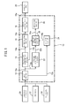
- a control device 10 of a machine tool 20 can be formed so as to include an NC device of the machine tool 20, and comprises an input section 12, a reading and interpreting section 14, a interpolating section 16, a servo-control section 18, a program analyzing section 22, a storage section 24, a process chart creating section 26 and a displaying section 28.
- the input section 12 may comprise a network means e.g., a LAN, a keyboard or a touch panel.
- the displaying section 28 can be formed by a display attached to an NC device of the machine tool 20.
- a machining program 30, tool data 32 and workpiece data 34 are input into the input section 12.
- the machining program 30 can be generated by using for example a CAM system.
- the tool data 32 includes coded information of tools such as tool lengths, tool diameters the number of cutting edges, and the tool types i.e., end mill, drill and tap, associated with the tool numbers.
- the tool data 32 may be stored in a server in relation to all of the tools used in a factory. From the server, the tool data may be sent to the input section 12 via a LAN.
- the tool data may be input by a CAM operator or an operator of the machine tool 20.
- the workpiece data 34 is data relative to a workpiece coordinate system determining a point on a surface of the workpiece as the origin.
- the workpiece data 34 may be sent from a CAD system to the input section 12 via a LAN.
- the workpiece data may be input by a CAM operator or an operator of the machine tool 20.
- the machining program 30 input into the input section 12 is output to the reading and interpreting section 14 as shown by an arrow 12a.
- the reading and interpreting section 14 reads and interprets so that operation commands 14a are output.
- the operation commands include the feeding amounts and speeds in the X-, Y- and Z-axis directions.
- the operation commands 14a which have been output by the reading and interpreting section 14, are sent to the interpolating section 16.
- the interpolating section 16 interpolates the operation commands 14, in the X-, Y- and Z-axis directions, via calculation based on an interpolation function, so that position commands (pulse position commands) 16a are output to the servo-control section 18 based on the respective X-, Y- and Z-axial feed speeds. Based on the respective X-, Y- and Z-axial position commands 16a, the servo-control section 18 outputs electric currents 18a to X-, Y- and Z-axial servomotors (not shown) of the machine tool 20, for driving X-, Y-and Z-axes of the machine tool 20 respectively.
- the machining program 30 is also sent to the program analyzing section 22 as shown by an arrow 12b.
- the program analyzing section 22 analyzes the machining program, written by G code or the like, so that the machining program is sent word by word to the process chart creating section 26, as shown by an arrow 22a.
- an arrow 14b shows the information of the running program which is sent to the process chart creating section 26 from the reading and interpreting section 14.
- the process chart creating section 26 creates a process chart based on the machining program, which has been read word by word from the program analyzing section 22, and the tool data from the storing section 24.
- the process char is displayed on the displaying section 26.
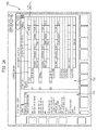
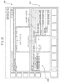
- a window 100 includes a schedule region 102 and a machining program region 104. Showing the schedule and the machining program simultaneously allows an operator to easily find an error in the machining program by simultaneously referring the schedule and the machining program.
- a part of the schedule is selected by tapping it with a pointing device or a cursor, the corresponding part in the machining program is highlighted and the cursor moves to the corresponding part in the machining program.
- the running process is highlighted based on running program block information from the reading and interpreting section 14. This facilitates understanding the correspondence between the schedule and the actual machining program.
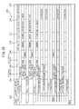
- the schedule 200 is composed of the respective processes of a machining program which are arranged in the execution sequence, and paragraphed in relation to the tools to be changed or the surfaces to be machined. Further, the schedule 200 includes items of tool type 202, subprogram 204, angle of the machined surface 206, coordinate system setting 208, spindle rotational speed 210, cutting feed speed 212, tool length correcting value 214 and tool diameter correcting value 216.
- the tool type 202 includes 1: face mill, 2: drill and 3: end mill.
- the details of the subprogram 204 are described in the portion indicated by reference 204.
- 0.0 degree around A-axis and C-axis is shown as the machined surface angle 206
- G54, G55 and G 56 are shown as the setting of coordinate system 208, which is generally designated by G54-G59 of the G-code
- 6000 (1/min) and 8000 (1/min) are shown as the spindle rotational speed 210, 2400 (mm/min)
- error and 12000 (mm/min) are shown as the cutting feed speed 212
- 80.1234 (mm) 234.5678 (mm) and 111.2222 (mm) are shown as the tool length correcting value 214 and 62.5 (mm) and 4.0 (mm) are shown as the tool diameter correcting value 216.
- the error indication means that the pertinent value is not described in the machining program.
- the program for creating the schedule 102 of Figure 3A may be formed as one of the subroutines of a program for managing the machining data of the control device 10. Therefore, storing the schedule 102 associated with the machining data facilitates understanding the detail of the machining program by displaying the schedule 102 within for example a preview window as shown in Figure 3C when used again on a later date.
- the preview window 300 for managing the machining data shown in Figure 3C as an example, includes a region 302 for displaying a schedule and a region 304 for displaying a list of file names of machining programs. When a program name in the region 304 is clicked or tapped, a past schedule, corresponding to the machining program, is displayed within the region 302.
- schedule 200 shown in Figure 3B includes the tool type 202, the subprogram 204, the machined surface angle 206, the coordinate system setting 208, the spindle rotational speed 210, the cutting feed speed 212, the tool length correcting value 214 and the tool diameter correcting value 216
- only specific item(s) may be displayed.
- only the tools, which are used for a specific machining program may be displayed as shown in Figure 4A .
- tool number 400, use/nonuse 402 of a tool pot, tool type 404, tool diameter 406, tool length 408 and the number of cutting edges of each of the tools used for a machining program 300.
- a list may be created for all of the tool used for a plurality of machining programs which may be executed, not for a single machining program.
- the tools (tool numbers 502-1 to 502-14), which are used for machining program (program number 0500) are indicated by circle marks. This prevents the tools, which may be used, to be mistakenly removed from a tool magazine.
- FIG. 5A only the coordinate system, which is used for a machining program, may be displayed.
- the definitions of the workpiece coordinate system command G54, G55 and G54.1, which are used for a machining program, indicated by program number 0100, are displayed. Accordingly, setting errors can be reduced by displaying only the coordinate systems which are used in a machining program.
- a list may be created for all of the coordinate system used for a plurality of machining programs which may be executed, not for a single machining program.
- the workpiece coordinate system commands G54 and G54.1 are overlapped in the machining programs O100 and 0200. In such a case, it is possible to indicate a warning 600 that a workpiece coordinate system is redundantly wrote in a plurality of machining programs. This prevents redundant use of a coordinate system by mistake.
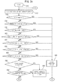
- step S10 After a schedule creating program is activated (step S10), the process chart creating section 26 reads one word of a machining program from the program analyzing section 22 (step S12). Then, through steps S14-S26, it is determined that the one word is the tool number, the spindle rotational speed, the speed of cutting feed, the positioning of a machined surface, the tool length correcting value, the tool diameter correcting value or the designation of an inclined surface.
- the command value is stored in a predetermined region of a memory (step S28), and the flow goes back to the step S12 so that the next one word of the machining program is read.
- step S30 it is determined whether or not the one word is a call command for calling a subprogram at step S30. If the one word is a call command for calling a subprogram (Yes at the step S30), then a command value of the subprogram is wrote to the schedule (step S34), and the flow goes back to the step S12 so that the next one word of the machining program is read.
- the one word is not a call command for calling a subprogram (No at the step S30)
- step S34 it is determined whether or not the one word is a tool changing command, at step S34. If the one word is a tool changing command (Yes at the step S34), it is determined whether or not a value of the tool number is stored in the memory region (step S36). At the step 36, if no tool number is stored in the memory region (Yes at the step S36), then a warning (error) is indicated in the schedule (step S40).
- step S42 If the one word is not a tool changing command (No at the step S34), then it is determined whether or not the one word is a spindle activating command at step S42. If the one word is a spindle activating command (Yes at the step S42), then it is determined whether or not a value of the spindle rotational speed is stored in the memory region (step S44). At the step S44, if no spindle rotational speed is stored in the memory region (Yes at the step S44), then a warning (error) is indicated in the schedule (step S46).
- step S48 it is determined whether or not the one word is a tool length correcting command at step S48. If the one word is a tool length correcting command (Yes at the step S48), then it is determined whether or not a tool length correcting value is stored in the memory region (step S50). At the step S50, if no tool length correcting value is stored in the memory region (Yes at the step S50), then a warning (error) is indicated in the schedule (step S52).
- step S54 If the one word is not a tool length correcting command (No at the step S48), then it is determined whether or not the one word is a tool diameter correcting command at step S54. If the one word is a tool diameter correcting command (Yes at the step S54), then it is determined whether or not a tool diameter correcting value is stored in the memory region (step S56). At the step S56, if no tool diameter correcting value is stored in the memory region (Yes at the step S56), then a warning (error) is indicated in the schedule (step S60).
- step S62 If the one word is not a tool diameter correcting command (No at the step S54), then it is determined whether or not the one word is an inclined surface designating command at step S62. If the one word is an inclined surface designating command (Yes at the step S62), then it is determined whether or not an inclined surface designating value is stored in the memory region (step S64). At the step S64, if no inclined surface designating correcting value is stored in the memory region (Yes at the step S64), then a warning (error) is indicated in the schedule (step S66).
- the one word is not an inclined surface designating command (No at the step S62), then it is determined whether or not the one word is a cutting mode switching command at step S68. If the one word is not a cutting mode switching command (No at the step S68), then it is determined whether or not the one word is a program ending command at step S70. If it is a program ending command(Yes at the step S70), then the schedule creating program is ended (step S72). If it is not a program ending command, then the flow goes back to the step S12 so that the next one word of the machining program is read.
- the one word is a cutting mode switching command (Yes at the step S68), then it is determined whether or not the cutting mode switching command is a switching command from a rapid feed mode to a cutting feed mode. If the one word is not a switching command from a rapid feed mode to a cutting feed mode (No at the step S74), then the flow goes back to the step S12 so that the next one word of the machining program is read.
- step S74 If the one word is a switching command from a rapid feed mode to a cutting feed mode, i.e., a command for starting a cutting process (Yes at the step S74), an angle information of the machined surface is wrote to the schedule (step S76), if the angle of the machined surface is changed. Then, it is determined whether or not a cutting feed speed is stored in a predetermined memory region (step S78). At the step S78, if no cutting feed speed is stored in the memory region (Yes at the step S78), then a warning (error) is indicated in the schedule (step S82), and the flow goes back to the step S12 so that the next one word of the machining program is read. If a cutting feed speed is is stored in the memory region (No at the step S78), then the cutting feed speed is wrote to the schedule (step S80), and the flow goes back to the step S12 so that the next one word of the machining program is read.
- the schedule of Figure 3A sorts the data on the basis of the tool to be used, so that the currently running machining process is indicated apparently in relation to "the used tool, the running machining program, the machined surface, the coordinate system and the machining condition". Further, by sorting the data on the basis of the machined surface, instead the tool to be used, the currently running machining process is indicated apparently in relation to "the machined surface, the used tool, the running machining program and the machining condition".
Abstract
Description
- The present invention relates to a control device for a machine tool which analyzes a machining program to extract commands in the machining program.
- In a machine tool controlled by an NC device, a workpiece is machined in accordance with a machining program. Machining programs are written with the known G-code and the like so that past machining programs can be reused, and a machining program can be used for another machine tool.
- For example,
Patent Literature 1 describes an NC machining system and method adapted to analyze the machining method based on an NC machining program so that the necessary machining conditions are extracted so as to store them to a database which can be used when creating an NC program. - Patent Literature 1:
WO 1998/019820 - According to the NC system and method described in
Patent Literature 1, machining conditions, which can be obtained only from an on-site know-how, a test cut or a simulation, can be surely extracted, along with program corrections or revisions, and formed into a database. Therefore, a knowledge base, which is very useful to create a database, can be easily composed. However, as described above, an NC program is described with the G-code or the like which it is not normally easily understood, and therefore the pre-check of a program requires much time in addition to an operator's skill and concentration. - Thus, it is very difficult for a regular operator to preliminary check a machining program (NC program) as to whether or not the spindle rotational speed, the cutting feed speed, the coordinate system and the tool type are correctly programmed or there is a setting omission.
- The invention is directed to solve the problem of the prior art, and the object of the invention is to provide a control device for a machine tool which allows an operator to easily understand the machining process and easily find a setting error in a machining program so that the machining program can be corrected.
- To achieve the already explained object, according to the present invention, a control device for controlling a machine tool based on a machining program, characterized by a program analyzing section for analyzing a machining program which has been input; a process chart creating section for creating a schedule by arranging the respective processes of a machining program in the execution sequence of the machining program, based on the results of the analysis conducted by the program analyzing section; and a displaying section for displaying the schedule created by the process chart creating section is provided.
- According to the invention, a machining program is analyzed and a process chart is displayed based on the analysis results, allowing an operator to easily understand the machining, find a setting error easily in the machining program and correct the machining program.
-
-
Figure 1 is a block diagram showing an example of a control device for a machine tool according to the invention. -
Figure 2A is a flow chart explaining the method for creating a process chart. -
Figure 2B is a flow chart explaining the method for creating a process chart. -
Figure 2C is a flow chart explaining the method for creating a process chart. -
Figure 2D is a flow chart explaining the method for creating a process chart. -
Figure 3A is an example of the process chart displayed on a displaying section of the control device ofFigure 1 . -
Figure 3B is a detailed illustration of the process chart ofFigure 3A . -
Figure 3C is an example of a preview window displayed on the displaying section of the control device ofFigure 1 . -
Figure 4A is an example of data of the tools to be used displayed on the displaying section of the control device ofFigure 1 . -
Figure 4B is an example of a list of the tools to be used displayed on the displaying section of the control device ofFigure 1 . -
Figure 5A is an example of a screen for setting the coordinate system displayed on the displaying section of the control device ofFigure 1 . -
Figure 5B is an example of a list of the coordinate systems to be used displayed on the displaying section of the control device ofFigure 1 . - With reference to the drawings, an embodiment of the invention will be described below.
- In
Figure 1 , acontrol device 10 of amachine tool 20 according to an embodiment of the invention can be formed so as to include an NC device of themachine tool 20, and comprises aninput section 12, a reading and interpretingsection 14, a interpolatingsection 16, a servo-control section 18, aprogram analyzing section 22, astorage section 24, a processchart creating section 26 and a displayingsection 28. Theinput section 12 may comprise a network means e.g., a LAN, a keyboard or a touch panel. The displayingsection 28 can be formed by a display attached to an NC device of themachine tool 20. - A
machining program 30,tool data 32 andworkpiece data 34 are input into theinput section 12. Themachining program 30 can be generated by using for example a CAM system. Thetool data 32 includes coded information of tools such as tool lengths, tool diameters the number of cutting edges, and the tool types i.e., end mill, drill and tap, associated with the tool numbers. Thetool data 32 may be stored in a server in relation to all of the tools used in a factory. From the server, the tool data may be sent to theinput section 12 via a LAN. The tool data may be input by a CAM operator or an operator of themachine tool 20. Theworkpiece data 34 is data relative to a workpiece coordinate system determining a point on a surface of the workpiece as the origin. Theworkpiece data 34 may be sent from a CAD system to theinput section 12 via a LAN. The workpiece data may be input by a CAM operator or an operator of themachine tool 20. - The
machining program 30 input into theinput section 12 is output to the reading and interpretingsection 14 as shown by anarrow 12a. The reading and interpretingsection 14 reads and interprets so thatoperation commands 14a are output. The operation commands include the feeding amounts and speeds in the X-, Y- and Z-axis directions. Theoperation commands 14a, which have been output by the reading and interpretingsection 14, are sent to the interpolatingsection 16. - The interpolating
section 16 interpolates theoperation commands 14, in the X-, Y- and Z-axis directions, via calculation based on an interpolation function, so that position commands (pulse position commands) 16a are output to the servo-control section 18 based on the respective X-, Y- and Z-axial feed speeds. Based on the respective X-, Y- and Z-axial position commands 16a, the servo-control section 18 outputselectric currents 18a to X-, Y- and Z-axial servomotors (not shown) of themachine tool 20, for driving X-, Y-and Z-axes of themachine tool 20 respectively. - The
machining program 30 is also sent to theprogram analyzing section 22 as shown by anarrow 12b. Theprogram analyzing section 22 analyzes the machining program, written by G code or the like, so that the machining program is sent word by word to the processchart creating section 26, as shown by an arrow 22a. Further, anarrow 14b shows the information of the running program which is sent to the processchart creating section 26 from the reading and interpretingsection 14. The processchart creating section 26 creates a process chart based on the machining program, which has been read word by word from theprogram analyzing section 22, and the tool data from thestoring section 24. The process char is displayed on the displayingsection 26. - With reference to
Figure 3A , an example of the process chart which is displayed on the displayingsection 28 is shown. InFigure 3A , awindow 100 includes aschedule region 102 and amachining program region 104. Showing the schedule and the machining program simultaneously allows an operator to easily find an error in the machining program by simultaneously referring the schedule and the machining program. When a part of the schedule is selected by tapping it with a pointing device or a cursor, the corresponding part in the machining program is highlighted and the cursor moves to the corresponding part in the machining program. Further, when the machining program is running, the running process is highlighted based on running program block information from the reading and interpretingsection 14. This facilitates understanding the correspondence between the schedule and the actual machining program. - With reference to
Figure 3B , the entire schedule, which is displayed in theregion 102, is shown. In this example, theschedule 200 is composed of the respective processes of a machining program which are arranged in the execution sequence, and paragraphed in relation to the tools to be changed or the surfaces to be machined. Further, theschedule 200 includes items oftool type 202,subprogram 204, angle of themachined surface 206,coordinate system setting 208, spindlerotational speed 210,cutting feed speed 212, toollength correcting value 214 and tooldiameter correcting value 216. - In
Figure 3B , thetool type 202 includes 1: face mill, 2: drill and 3: end mill. The details of thesubprogram 204 are described in the portion indicated byreference 204. Further, in the example ofFigure 3B , 0.0 degree around A-axis and C-axis is shown as the machinedsurface angle 206, G54, G55 andG 56 are shown as the setting of coordinatesystem 208, which is generally designated by G54-G59 of the G-code, 4000 (1/min), 6000 (1/min) and 8000 (1/min) are shown as the spindlerotational speed 210, 2400 (mm/min), error and 12000 (mm/min) are shown as thecutting feed speed 212, and 80.1234 (mm), 234.5678 (mm) and 111.2222 (mm) are shown as the toollength correcting value 214 and 62.5 (mm) and 4.0 (mm) are shown as the tooldiameter correcting value 216. The error indication means that the pertinent value is not described in the machining program. - The program for creating the
schedule 102 ofFigure 3A may be formed as one of the subroutines of a program for managing the machining data of thecontrol device 10. Therefore, storing theschedule 102 associated with the machining data facilitates understanding the detail of the machining program by displaying theschedule 102 within for example a preview window as shown inFigure 3C when used again on a later date. Thepreview window 300 for managing the machining data, shown inFigure 3C as an example, includes aregion 302 for displaying a schedule and aregion 304 for displaying a list of file names of machining programs. When a program name in theregion 304 is clicked or tapped, a past schedule, corresponding to the machining program, is displayed within theregion 302. - Although,
schedule 200 shown inFigure 3B includes thetool type 202, thesubprogram 204, the machinedsurface angle 206, the coordinate system setting 208, the spindlerotational speed 210, the cuttingfeed speed 212, the toollength correcting value 214 and the tooldiameter correcting value 216, only specific item(s) may be displayed. For example, only the tools, which are used for a specific machining program, may be displayed as shown inFigure 4A . In the example ofFigure 4A ,tool number 400, use/nonuse 402 of a tool pot,tool type 404,tool diameter 406,tool length 408 and the number of cutting edges of each of the tools used for amachining program 300. Accordingly, setting errors can be reduced by displaying only the data relative to the tools used for a specific machining program. Further, as shown inFigure 4B , a list may be created for all of the tool used for a plurality of machining programs which may be executed, not for a single machining program. In the example ofFigure 4B , the tools (tool numbers 502-1 to 502-14), which are used for machining program (program number 0500) are indicated by circle marks. This prevents the tools, which may be used, to be mistakenly removed from a tool magazine. - Further, as shown in
Figure 5A , only the coordinate system, which is used for a machining program, may be displayed. In the example ofFigure 5A , the definitions of the workpiece coordinate system command G54, G55 and G54.1, which are used for a machining program, indicated byprogram number 0100, are displayed. Accordingly, setting errors can be reduced by displaying only the coordinate systems which are used in a machining program. Further, as shown inFigure 5B , a list may be created for all of the coordinate system used for a plurality of machining programs which may be executed, not for a single machining program. In the example ofFigure 5B , the workpiece coordinate system commands G54 and G54.1 are overlapped in the machining programs O100 and 0200. In such a case, it is possible to indicate awarning 600 that a workpiece coordinate system is redundantly wrote in a plurality of machining programs. This prevents redundant use of a coordinate system by mistake. - With reference to a flow chart shown in
figures 2A-2D , a method for creating the schedule, below. - After a schedule creating program is activated (step S10), the process
chart creating section 26 reads one word of a machining program from the program analyzing section 22 (step S12). Then, through steps S14-S26, it is determined that the one word is the tool number, the spindle rotational speed, the speed of cutting feed, the positioning of a machined surface, the tool length correcting value, the tool diameter correcting value or the designation of an inclined surface. If the one word is one of the tool number, the spindle rotational speed, the speed of cutting feed, the positioning of a machined surface, the tool length correcting value, the tool diameter correcting value and the designation of an inclined surface, i.e., Yes at one of the steps S14-S26, then the command value is stored in a predetermined region of a memory (step S28), and the flow goes back to the step S12 so that the next one word of the machining program is read. - If the judgment is No at any one of the steps S14-S26, then it is determined whether or not the one word is a call command for calling a subprogram at step S30. If the one word is a call command for calling a subprogram (Yes at the step S30), then a command value of the subprogram is wrote to the schedule (step S34), and the flow goes back to the step S12 so that the next one word of the machining program is read.
- If the one word is not a call command for calling a subprogram (No at the step S30), then it is determined whether or not the one word is a designation command for designating a workpiece coordinate system, at step S32. If the one word is a designation command for designating a workpiece coordinate system (Yes at the step S32), then the command value of designation of the workpiece coordinate system is wrote to the schedule, and the flow goes back to the step S12 so that the next one word of the machining program is read.
- If the one work is not a designation of a workpiece coordinate system (No at the step S32), then it is determined whether or not the one word is a tool changing command, at step S34. If the one word is a tool changing command (Yes at the step S34), it is determined whether or not a value of the tool number is stored in the memory region (step S36). At the
step 36, if no tool number is stored in the memory region (Yes at the step S36), then a warning (error) is indicated in the schedule (step S40). If a tool number is stored in the memory region (No at the step 36), then the value (the tool number) which is stored in the memory is wrote to the schedule, the memory region is cleared (the step S38), and the flow goes back to the step S12 so that the next one word of the machining program is read. - If the one word is not a tool changing command (No at the step S34), then it is determined whether or not the one word is a spindle activating command at step S42. If the one word is a spindle activating command (Yes at the step S42), then it is determined whether or not a value of the spindle rotational speed is stored in the memory region (step S44). At the step S44, if no spindle rotational speed is stored in the memory region (Yes at the step S44), then a warning (error) is indicated in the schedule (step S46).
- If a spindle rotational speed is stored in the memory region (No at the step 44), then the value (the spindle rotational speed) which is stored in the memory is wrote to the schedule, the memory region is cleared (the step S38), and the flow goes back to the step S12 so that the next one word of the machining program is read.
- If the one word is not a spindle activating command (No at the step S42), then it is determined whether or not the one word is a tool length correcting command at step S48. If the one word is a tool length correcting command (Yes at the step S48), then it is determined whether or not a tool length correcting value is stored in the memory region (step S50). At the step S50, if no tool length correcting value is stored in the memory region (Yes at the step S50), then a warning (error) is indicated in the schedule (step S52).
- If a tool length correcting value is stored in the memory region (No at the step 50), then the value (the tool length correcting value) which is stored in the memory is wrote to the schedule, the memory region is cleared (the step S38), and the flow goes back to the step S12 so that the next one word of the machining program is read.
- If the one word is not a tool length correcting command (No at the step S48), then it is determined whether or not the one word is a tool diameter correcting command at step S54. If the one word is a tool diameter correcting command (Yes at the step S54), then it is determined whether or not a tool diameter correcting value is stored in the memory region (step S56). At the step S56, if no tool diameter correcting value is stored in the memory region (Yes at the step S56), then a warning (error) is indicated in the schedule (step S60). If a tool diameter correcting value is stored in the memory region (No at the step 56), then the value (the tool diameter correcting value) which is stored in the memory is wrote to the schedule, the memory region is cleared (the step S58), and the flow goes back to the step S12 so that the next one word of the machining program is read.
- If the one word is not a tool diameter correcting command (No at the step S54), then it is determined whether or not the one word is an inclined surface designating command at step S62. If the one word is an inclined surface designating command (Yes at the step S62), then it is determined whether or not an inclined surface designating value is stored in the memory region (step S64). At the step S64, if no inclined surface designating correcting value is stored in the memory region (Yes at the step S64), then a warning (error) is indicated in the schedule (step S66). If an inclined surface designating value is stored in the memory region (No at the step S64), then the value (the inclined surface designating value) which is stored in the memory is wrote to the schedule, the memory region is cleared (the step S58), and the flow goes back to the step S12 so that the next one word of the machining program is read.
- If the one word is not an inclined surface designating command (No at the step S62), then it is determined whether or not the one word is a cutting mode switching command at step S68. If the one word is not a cutting mode switching command (No at the step S68), then it is determined whether or not the one word is a program ending command at step S70. If it is a program ending command(Yes at the step S70), then the schedule creating program is ended (step S72). If it is not a program ending command, then the flow goes back to the step S12 so that the next one word of the machining program is read.
- If the one word is a cutting mode switching command (Yes at the step S68), then it is determined whether or not the cutting mode switching command is a switching command from a rapid feed mode to a cutting feed mode. If the one word is not a switching command from a rapid feed mode to a cutting feed mode (No at the step S74), then the flow goes back to the step S12 so that the next one word of the machining program is read.
- If the one word is a switching command from a rapid feed mode to a cutting feed mode, i.e., a command for starting a cutting process (Yes at the step S74), an angle information of the machined surface is wrote to the schedule (step S76), if the angle of the machined surface is changed. Then, it is determined whether or not a cutting feed speed is stored in a predetermined memory region (step S78). At the step S78, if no cutting feed speed is stored in the memory region (Yes at the step S78), then a warning (error) is indicated in the schedule (step S82), and the flow goes back to the step S12 so that the next one word of the machining program is read. If a cutting feed speed is is stored in the memory region (No at the step S78), then the cutting feed speed is wrote to the schedule (step S80), and the flow goes back to the step S12 so that the next one word of the machining program is read.
- The schedule of
Figure 3A sorts the data on the basis of the tool to be used, so that the currently running machining process is indicated apparently in relation to "the used tool, the running machining program, the machined surface, the coordinate system and the machining condition". Further, by sorting the data on the basis of the machined surface, instead the tool to be used, the currently running machining process is indicated apparently in relation to "the machined surface, the used tool, the running machining program and the machining condition". - As described above, an error is indicated when a necessary program information is not described in a machining program or there is no subprogram which should be called, enabling the machining program to be corrected easily.
-
- 10
- Control Device
- 12
- Input Section
- 14
- Reading and Interpreting Section
- 16
- Interpolating Section
- 18
- Servo-Control Section
- 20
- Machine Tool
- 22
- Program Analyzing Section
- 24
- Storing Section
- 26
- Process Chart Creating Section
- 28
- Displaying Section
- 30
- Machining Program
- 32
- Tool Data
- 34
- Workpiece Data
Claims (5)
- A control device for controlling a machine tool based on a machining program, characterized by:a program analyzing section for analyzing a machining program which has been input;a process chart creating section for creating a schedule by arranging the respective processes of a machining program in the execution sequence of the machining program, based on the results of the analysis conducted by the program analyzing section; anda displaying section for displaying the schedule created by the process chart creating section.
- The control device according to claim 1, further comprising an input section, the machining program being input through the input section along with tool data and workpiece data.
- The control device according to claim 1, wherein the schedule includes paragraphs separated based on the tool change or the machined surfaces.
- The control device according to claim 1, wherein the schedule includes information in relation to the tool type, the subprogram, the angle of the machined surface, the designation of coordinate system, the spindle rotational speed, the cutting feed speed, the tool length correcting value and the tool diameter correcting value.
- The control device according to claim 4, wherein an error is indicated when the information relative to the tool type, the subprogram, the angle of the machined surface, the designation of the coordinate system, the spindle rotational speed, the cutting feed speed, the tool length correcting value and/or the tool diameter correcting value is contradict with corresponding command described in the machining program.
Applications Claiming Priority (1)
| Application Number | Priority Date | Filing Date | Title |
|---|---|---|---|
| PCT/JP2013/085182 WO2015097887A1 (en) | 2013-12-27 | 2013-12-27 | Control apparatus for machine tool |
Publications (3)
| Publication Number | Publication Date |
|---|---|
| EP3088978A1 true EP3088978A1 (en) | 2016-11-02 |
| EP3088978A4 EP3088978A4 (en) | 2017-09-06 |
| EP3088978B1 EP3088978B1 (en) | 2019-12-04 |
Family
ID=53477816
Family Applications (1)
| Application Number | Title | Priority Date | Filing Date |
|---|---|---|---|
| EP13900527.6A Active EP3088978B1 (en) | 2013-12-27 | 2013-12-27 | Control apparatus for machine tool |
Country Status (5)
| Country | Link |
|---|---|
| US (1) | US10133258B2 (en) |
| EP (1) | EP3088978B1 (en) |
| JP (1) | JP6261613B2 (en) |
| CN (1) | CN105849659B (en) |
| WO (1) | WO2015097887A1 (en) |
Families Citing this family (8)
| Publication number | Priority date | Publication date | Assignee | Title |
|---|---|---|---|---|
| JP6373395B2 (en) * | 2014-09-30 | 2018-08-15 | 株式会社牧野フライス製作所 | Machine tool control device and machine tool |
| WO2016071414A1 (en) * | 2014-11-07 | 2016-05-12 | Nuovo Pignone Srl | Method for generating a machining program and machine tool |
| JP6309910B2 (en) * | 2015-03-30 | 2018-04-11 | ファナック株式会社 | Numerical control device with program display function with high visibility |
| JP6506334B2 (en) * | 2017-03-14 | 2019-04-24 | ファナック株式会社 | Production management device and production system |
| JP6448860B1 (en) * | 2017-11-15 | 2019-01-09 | 三菱電機株式会社 | Numerical control apparatus and display method |
| JP6640822B2 (en) * | 2017-12-06 | 2020-02-05 | ファナック株式会社 | Numerical control unit |
| JP6760985B2 (en) * | 2018-03-06 | 2020-09-23 | ファナック株式会社 | Operation management device |
| JP7440614B2 (en) | 2020-03-18 | 2024-02-28 | ファナック株式会社 | Program analysis device and control system |
Family Cites Families (21)
| Publication number | Priority date | Publication date | Assignee | Title |
|---|---|---|---|---|
| JPS62105202A (en) * | 1985-10-31 | 1987-05-15 | Fanuc Ltd | Nc data generating method |
| JPH01291307A (en) * | 1988-05-18 | 1989-11-22 | Fanuc Ltd | Working program generating system |
| JP2712442B2 (en) * | 1988-12-19 | 1998-02-10 | トヨタ自動車株式会社 | Shellfish use order determination system |
| JP2901353B2 (en) | 1990-12-28 | 1999-06-07 | オークマ株式会社 | Numerical control device with machining program editing function for numerically controlled machine tools |
| JPH05289729A (en) * | 1992-04-07 | 1993-11-05 | Fanuc Ltd | Step execution system for cad/cam system |
| DE4329016A1 (en) * | 1993-08-30 | 1995-03-09 | Heidenhain Gmbh Dr Johannes | Procedure for creating and / or changing NC programs |
| JP3694323B2 (en) * | 1996-11-07 | 2005-09-14 | 株式会社森精機製作所 | NC program analysis method and apparatus in NC machining |
| EP1018676A1 (en) * | 1998-08-24 | 2000-07-12 | Okuma Corporation | Method and apparatus for nc machining support |
| JP4390093B2 (en) | 2000-09-14 | 2009-12-24 | 株式会社森精機製作所 | Automatic programming and simulation equipment |
| JP4738585B2 (en) * | 2000-10-26 | 2011-08-03 | シチズンホールディングス株式会社 | Machining program graph display method and apparatus therefor |
| DE10308815B4 (en) * | 2003-02-27 | 2008-06-05 | Siemens Ag | Method for generating and visualizing a task-oriented step representation |
| JP2006099284A (en) * | 2004-09-28 | 2006-04-13 | Fanuc Ltd | Numerical controller |
| JP2007133787A (en) * | 2005-11-11 | 2007-05-31 | Nissan Motor Co Ltd | Working device and working method |
| JP4745891B2 (en) | 2006-05-26 | 2011-08-10 | 株式会社ソディック | Machining data generator |
| JP2008226112A (en) * | 2007-03-15 | 2008-09-25 | Mitsubishi Electric Corp | Numerically controlled apparatus |
| CN102016733B (en) * | 2008-04-22 | 2013-06-12 | 三菱电机株式会社 | Numerical control method and apparatus therefor |
| JP2010067101A (en) * | 2008-09-12 | 2010-03-25 | Toshiba Mach Co Ltd | Method of setting interference region of tool |
| JP2011059801A (en) * | 2009-09-07 | 2011-03-24 | Mitsubishi Electric Corp | Program creation/instruction device and method |
| JP5778430B2 (en) * | 2011-01-12 | 2015-09-16 | Dmg森精機株式会社 | Machine tool controller |
| JP5817256B2 (en) * | 2011-06-29 | 2015-11-18 | 株式会社ジェイテクト | Machine control program creation device |
| TWI446130B (en) * | 2011-11-28 | 2014-07-21 | Foxnum Technology Co Ltd | System and method for editting a processing file of a cnc machine |
-
2013
- 2013-12-27 JP JP2015554465A patent/JP6261613B2/en active Active
- 2013-12-27 CN CN201380081851.7A patent/CN105849659B/en active Active
- 2013-12-27 WO PCT/JP2013/085182 patent/WO2015097887A1/en active Application Filing
- 2013-12-27 US US15/108,195 patent/US10133258B2/en active Active
- 2013-12-27 EP EP13900527.6A patent/EP3088978B1/en active Active
Also Published As
| Publication number | Publication date |
|---|---|
| CN105849659B (en) | 2019-08-13 |
| WO2015097887A1 (en) | 2015-07-02 |
| US10133258B2 (en) | 2018-11-20 |
| EP3088978A4 (en) | 2017-09-06 |
| JPWO2015097887A1 (en) | 2017-03-23 |
| US20160327938A1 (en) | 2016-11-10 |
| CN105849659A (en) | 2016-08-10 |
| JP6261613B2 (en) | 2018-01-17 |
| EP3088978B1 (en) | 2019-12-04 |
Similar Documents
| Publication | Publication Date | Title |
|---|---|---|
| EP3088978B1 (en) | Control apparatus for machine tool | |
| US10775768B2 (en) | Machine control program creating device | |
| US6671571B1 (en) | Method for NC- programming and system for NC- machining | |
| CN107300891B (en) | Parameter setting device and parameter setting method | |
| US9665085B2 (en) | Cutting condition and tool life display device for a numerical controller | |
| JP3827951B2 (en) | NC program optimization method and apparatus in NC machining | |
| CN105793788B (en) | The control device of work mechanism | |
| JP5925976B1 (en) | Machining program editing support device | |
| US20090164038A1 (en) | Method for optimizing the machining process in a machine | |
| US11947332B2 (en) | CAD data-based automatic operation device of machining center | |
| JP5990662B2 (en) | Machining program editing support device | |
| US10551822B2 (en) | CAD/CAM-CNC integrated system | |
| US20190303517A1 (en) | Simulation device | |
| JPWO2018122986A1 (en) | Machining program analyzer | |
| CN110737244A (en) | Numerical controller and data editing method | |
| JP6638979B2 (en) | Numerical control device with machining process management function and machining process management program | |
| KR102182204B1 (en) | Automatic selection method for machine tool process condition | |
| CN112805638B (en) | NC program conversion processing method and conversion computer | |
| US6658317B2 (en) | Method for setting a moving position in a machine tool | |
| US20220342381A1 (en) | Managing a machine tool method, for example method of mapping toolpath data and machine code, a control device, and a machine tool | |
| KR102188017B1 (en) | Measurement and Management System for Mold Manufacture Machine | |
| Brecher et al. | Numerical Controllers | |
| US20110288676A1 (en) | Method and device for the simplification of machine control process sequences | |
| Rahou et al. | Development Of A Software Module For Nc Programming In Industrial Environment | |
| KR100401635B1 (en) | Method for check grammer a manufacture programming of numerical control type machine tool |
Legal Events
| Date | Code | Title | Description |
|---|---|---|---|
| PUAI | Public reference made under article 153(3) epc to a published international application that has entered the european phase |
Free format text: ORIGINAL CODE: 0009012 |
|
| 17P | Request for examination filed |
Effective date: 20160718 |
|
| AK | Designated contracting states |
Kind code of ref document: A1 Designated state(s): AL AT BE BG CH CY CZ DE DK EE ES FI FR GB GR HR HU IE IS IT LI LT LU LV MC MK MT NL NO PL PT RO RS SE SI SK SM TR |
|
| AX | Request for extension of the european patent |
Extension state: BA ME |
|
| DAX | Request for extension of the european patent (deleted) | ||
| REG | Reference to a national code |
Ref country code: DE Ref legal event code: R079 Ref document number: 602013063773 Country of ref document: DE Free format text: PREVIOUS MAIN CLASS: G05B0019406000 Ipc: G05B0019409300 |
|
| A4 | Supplementary search report drawn up and despatched |
Effective date: 20170808 |
|
| RIC1 | Information provided on ipc code assigned before grant |
Ipc: G05B 19/4093 20060101AFI20170802BHEP Ipc: G05B 19/4068 20060101ALI20170802BHEP |
|
| GRAP | Despatch of communication of intention to grant a patent |
Free format text: ORIGINAL CODE: EPIDOSNIGR1 |
|
| STAA | Information on the status of an ep patent application or granted ep patent |
Free format text: STATUS: GRANT OF PATENT IS INTENDED |
|
| INTG | Intention to grant announced |
Effective date: 20190710 |
|
| GRAS | Grant fee paid |
Free format text: ORIGINAL CODE: EPIDOSNIGR3 |
|
| GRAA | (expected) grant |
Free format text: ORIGINAL CODE: 0009210 |
|
| STAA | Information on the status of an ep patent application or granted ep patent |
Free format text: STATUS: THE PATENT HAS BEEN GRANTED |
|
| AK | Designated contracting states |
Kind code of ref document: B1 Designated state(s): AL AT BE BG CH CY CZ DE DK EE ES FI FR GB GR HR HU IE IS IT LI LT LU LV MC MK MT NL NO PL PT RO RS SE SI SK SM TR |
|
| REG | Reference to a national code |
Ref country code: GB Ref legal event code: FG4D |
|
| REG | Reference to a national code |
Ref country code: CH Ref legal event code: EP |
|
| REG | Reference to a national code |
Ref country code: AT Ref legal event code: REF Ref document number: 1210154 Country of ref document: AT Kind code of ref document: T Effective date: 20191215 |
|
| REG | Reference to a national code |
Ref country code: DE Ref legal event code: R096 Ref document number: 602013063773 Country of ref document: DE |
|
| REG | Reference to a national code |
Ref country code: IE Ref legal event code: FG4D |
|
| REG | Reference to a national code |
Ref country code: NL Ref legal event code: MP Effective date: 20191204 |
|
| REG | Reference to a national code |
Ref country code: LT Ref legal event code: MG4D |
|
| PG25 | Lapsed in a contracting state [announced via postgrant information from national office to epo] |
Ref country code: SE Free format text: LAPSE BECAUSE OF FAILURE TO SUBMIT A TRANSLATION OF THE DESCRIPTION OR TO PAY THE FEE WITHIN THE PRESCRIBED TIME-LIMIT Effective date: 20191204 Ref country code: LV Free format text: LAPSE BECAUSE OF FAILURE TO SUBMIT A TRANSLATION OF THE DESCRIPTION OR TO PAY THE FEE WITHIN THE PRESCRIBED TIME-LIMIT Effective date: 20191204 Ref country code: LT Free format text: LAPSE BECAUSE OF FAILURE TO SUBMIT A TRANSLATION OF THE DESCRIPTION OR TO PAY THE FEE WITHIN THE PRESCRIBED TIME-LIMIT Effective date: 20191204 Ref country code: NO Free format text: LAPSE BECAUSE OF FAILURE TO SUBMIT A TRANSLATION OF THE DESCRIPTION OR TO PAY THE FEE WITHIN THE PRESCRIBED TIME-LIMIT Effective date: 20200304 Ref country code: GR Free format text: LAPSE BECAUSE OF FAILURE TO SUBMIT A TRANSLATION OF THE DESCRIPTION OR TO PAY THE FEE WITHIN THE PRESCRIBED TIME-LIMIT Effective date: 20200305 Ref country code: FI Free format text: LAPSE BECAUSE OF FAILURE TO SUBMIT A TRANSLATION OF THE DESCRIPTION OR TO PAY THE FEE WITHIN THE PRESCRIBED TIME-LIMIT Effective date: 20191204 Ref country code: BG Free format text: LAPSE BECAUSE OF FAILURE TO SUBMIT A TRANSLATION OF THE DESCRIPTION OR TO PAY THE FEE WITHIN THE PRESCRIBED TIME-LIMIT Effective date: 20200304 |
|
| PG25 | Lapsed in a contracting state [announced via postgrant information from national office to epo] |
Ref country code: HR Free format text: LAPSE BECAUSE OF FAILURE TO SUBMIT A TRANSLATION OF THE DESCRIPTION OR TO PAY THE FEE WITHIN THE PRESCRIBED TIME-LIMIT Effective date: 20191204 Ref country code: RS Free format text: LAPSE BECAUSE OF FAILURE TO SUBMIT A TRANSLATION OF THE DESCRIPTION OR TO PAY THE FEE WITHIN THE PRESCRIBED TIME-LIMIT Effective date: 20191204 |
|
| PG25 | Lapsed in a contracting state [announced via postgrant information from national office to epo] |
Ref country code: AL Free format text: LAPSE BECAUSE OF FAILURE TO SUBMIT A TRANSLATION OF THE DESCRIPTION OR TO PAY THE FEE WITHIN THE PRESCRIBED TIME-LIMIT Effective date: 20191204 |
|
| PG25 | Lapsed in a contracting state [announced via postgrant information from national office to epo] |
Ref country code: CZ Free format text: LAPSE BECAUSE OF FAILURE TO SUBMIT A TRANSLATION OF THE DESCRIPTION OR TO PAY THE FEE WITHIN THE PRESCRIBED TIME-LIMIT Effective date: 20191204 Ref country code: RO Free format text: LAPSE BECAUSE OF FAILURE TO SUBMIT A TRANSLATION OF THE DESCRIPTION OR TO PAY THE FEE WITHIN THE PRESCRIBED TIME-LIMIT Effective date: 20191204 Ref country code: PT Free format text: LAPSE BECAUSE OF FAILURE TO SUBMIT A TRANSLATION OF THE DESCRIPTION OR TO PAY THE FEE WITHIN THE PRESCRIBED TIME-LIMIT Effective date: 20200429 Ref country code: NL Free format text: LAPSE BECAUSE OF FAILURE TO SUBMIT A TRANSLATION OF THE DESCRIPTION OR TO PAY THE FEE WITHIN THE PRESCRIBED TIME-LIMIT Effective date: 20191204 Ref country code: EE Free format text: LAPSE BECAUSE OF FAILURE TO SUBMIT A TRANSLATION OF THE DESCRIPTION OR TO PAY THE FEE WITHIN THE PRESCRIBED TIME-LIMIT Effective date: 20191204 Ref country code: ES Free format text: LAPSE BECAUSE OF FAILURE TO SUBMIT A TRANSLATION OF THE DESCRIPTION OR TO PAY THE FEE WITHIN THE PRESCRIBED TIME-LIMIT Effective date: 20191204 |
|
| REG | Reference to a national code |
Ref country code: CH Ref legal event code: PL |
|
| REG | Reference to a national code |
Ref country code: BE Ref legal event code: MM Effective date: 20191231 |
|
| PG25 | Lapsed in a contracting state [announced via postgrant information from national office to epo] |
Ref country code: IS Free format text: LAPSE BECAUSE OF FAILURE TO SUBMIT A TRANSLATION OF THE DESCRIPTION OR TO PAY THE FEE WITHIN THE PRESCRIBED TIME-LIMIT Effective date: 20200404 Ref country code: SK Free format text: LAPSE BECAUSE OF FAILURE TO SUBMIT A TRANSLATION OF THE DESCRIPTION OR TO PAY THE FEE WITHIN THE PRESCRIBED TIME-LIMIT Effective date: 20191204 Ref country code: SM Free format text: LAPSE BECAUSE OF FAILURE TO SUBMIT A TRANSLATION OF THE DESCRIPTION OR TO PAY THE FEE WITHIN THE PRESCRIBED TIME-LIMIT Effective date: 20191204 |
|
| REG | Reference to a national code |
Ref country code: DE Ref legal event code: R097 Ref document number: 602013063773 Country of ref document: DE |
|
| REG | Reference to a national code |
Ref country code: AT Ref legal event code: MK05 Ref document number: 1210154 Country of ref document: AT Kind code of ref document: T Effective date: 20191204 |
|
| PG25 | Lapsed in a contracting state [announced via postgrant information from national office to epo] |
Ref country code: MC Free format text: LAPSE BECAUSE OF FAILURE TO SUBMIT A TRANSLATION OF THE DESCRIPTION OR TO PAY THE FEE WITHIN THE PRESCRIBED TIME-LIMIT Effective date: 20191204 |
|
| PLBE | No opposition filed within time limit |
Free format text: ORIGINAL CODE: 0009261 |
|
| STAA | Information on the status of an ep patent application or granted ep patent |
Free format text: STATUS: NO OPPOSITION FILED WITHIN TIME LIMIT |
|
| PG25 | Lapsed in a contracting state [announced via postgrant information from national office to epo] |
Ref country code: DK Free format text: LAPSE BECAUSE OF FAILURE TO SUBMIT A TRANSLATION OF THE DESCRIPTION OR TO PAY THE FEE WITHIN THE PRESCRIBED TIME-LIMIT Effective date: 20191204 Ref country code: LU Free format text: LAPSE BECAUSE OF NON-PAYMENT OF DUE FEES Effective date: 20191227 Ref country code: IE Free format text: LAPSE BECAUSE OF NON-PAYMENT OF DUE FEES Effective date: 20191227 |
|
| 26N | No opposition filed |
Effective date: 20200907 |
|
| PG25 | Lapsed in a contracting state [announced via postgrant information from national office to epo] |
Ref country code: LI Free format text: LAPSE BECAUSE OF NON-PAYMENT OF DUE FEES Effective date: 20191231 Ref country code: BE Free format text: LAPSE BECAUSE OF NON-PAYMENT OF DUE FEES Effective date: 20191231 Ref country code: CH Free format text: LAPSE BECAUSE OF NON-PAYMENT OF DUE FEES Effective date: 20191231 Ref country code: PL Free format text: LAPSE BECAUSE OF FAILURE TO SUBMIT A TRANSLATION OF THE DESCRIPTION OR TO PAY THE FEE WITHIN THE PRESCRIBED TIME-LIMIT Effective date: 20191204 Ref country code: AT Free format text: LAPSE BECAUSE OF FAILURE TO SUBMIT A TRANSLATION OF THE DESCRIPTION OR TO PAY THE FEE WITHIN THE PRESCRIBED TIME-LIMIT Effective date: 20191204 Ref country code: SI Free format text: LAPSE BECAUSE OF FAILURE TO SUBMIT A TRANSLATION OF THE DESCRIPTION OR TO PAY THE FEE WITHIN THE PRESCRIBED TIME-LIMIT Effective date: 20191204 |
|
| PG25 | Lapsed in a contracting state [announced via postgrant information from national office to epo] |
Ref country code: CY Free format text: LAPSE BECAUSE OF FAILURE TO SUBMIT A TRANSLATION OF THE DESCRIPTION OR TO PAY THE FEE WITHIN THE PRESCRIBED TIME-LIMIT Effective date: 20191204 |
|
| PG25 | Lapsed in a contracting state [announced via postgrant information from national office to epo] |
Ref country code: HU Free format text: LAPSE BECAUSE OF FAILURE TO SUBMIT A TRANSLATION OF THE DESCRIPTION OR TO PAY THE FEE WITHIN THE PRESCRIBED TIME-LIMIT; INVALID AB INITIO Effective date: 20131227 Ref country code: MT Free format text: LAPSE BECAUSE OF FAILURE TO SUBMIT A TRANSLATION OF THE DESCRIPTION OR TO PAY THE FEE WITHIN THE PRESCRIBED TIME-LIMIT Effective date: 20191204 |
|
| PG25 | Lapsed in a contracting state [announced via postgrant information from national office to epo] |
Ref country code: TR Free format text: LAPSE BECAUSE OF FAILURE TO SUBMIT A TRANSLATION OF THE DESCRIPTION OR TO PAY THE FEE WITHIN THE PRESCRIBED TIME-LIMIT Effective date: 20191204 |
|
| PG25 | Lapsed in a contracting state [announced via postgrant information from national office to epo] |
Ref country code: MK Free format text: LAPSE BECAUSE OF FAILURE TO SUBMIT A TRANSLATION OF THE DESCRIPTION OR TO PAY THE FEE WITHIN THE PRESCRIBED TIME-LIMIT Effective date: 20191204 |
|
| PGFP | Annual fee paid to national office [announced via postgrant information from national office to epo] |
Ref country code: GB Payment date: 20231214 Year of fee payment: 11 |
|
| PGFP | Annual fee paid to national office [announced via postgrant information from national office to epo] |
Ref country code: IT Payment date: 20231123 Year of fee payment: 11 Ref country code: FR Payment date: 20231027 Year of fee payment: 11 Ref country code: DE Payment date: 20231221 Year of fee payment: 11 |