EP3088858A1 - Temperature measurement method for ultraviolet transmittance member, temperature measurement device for ultraviolet transmittance member, and light source device - Google Patents
Temperature measurement method for ultraviolet transmittance member, temperature measurement device for ultraviolet transmittance member, and light source device Download PDFInfo
- Publication number
- EP3088858A1 EP3088858A1 EP14874513.6A EP14874513A EP3088858A1 EP 3088858 A1 EP3088858 A1 EP 3088858A1 EP 14874513 A EP14874513 A EP 14874513A EP 3088858 A1 EP3088858 A1 EP 3088858A1
- Authority
- EP
- European Patent Office
- Prior art keywords
- ultraviolet light
- light transmittance
- temperature
- transmittance member
- wavelength
- Prior art date
- Legal status (The legal status is an assumption and is not a legal conclusion. Google has not performed a legal analysis and makes no representation as to the accuracy of the status listed.)
- Withdrawn
Links
- 238000002834 transmittance Methods 0.000 title claims abstract description 170
- 238000009529 body temperature measurement Methods 0.000 title claims abstract description 70
- 238000000034 method Methods 0.000 title claims abstract description 33
- 238000010521 absorption reaction Methods 0.000 claims abstract description 127
- 238000005259 measurement Methods 0.000 claims abstract description 55
- 238000004364 calculation method Methods 0.000 claims abstract description 42
- 238000001816 cooling Methods 0.000 claims description 26
- 239000000463 material Substances 0.000 claims description 24
- WUKWITHWXAAZEY-UHFFFAOYSA-L calcium difluoride Chemical group [F-].[F-].[Ca+2] WUKWITHWXAAZEY-UHFFFAOYSA-L 0.000 claims description 22
- 229910001634 calcium fluoride Inorganic materials 0.000 claims description 16
- YZCKVEUIGOORGS-OUBTZVSYSA-N Deuterium Chemical compound [2H] YZCKVEUIGOORGS-OUBTZVSYSA-N 0.000 description 30
- 229910052805 deuterium Inorganic materials 0.000 description 30
- 230000003595 spectral effect Effects 0.000 description 22
- 238000000295 emission spectrum Methods 0.000 description 21
- 239000013078 crystal Substances 0.000 description 18
- 238000010586 diagram Methods 0.000 description 15
- 230000005540 biological transmission Effects 0.000 description 13
- VYPSYNLAJGMNEJ-UHFFFAOYSA-N Silicium dioxide Chemical compound O=[Si]=O VYPSYNLAJGMNEJ-UHFFFAOYSA-N 0.000 description 12
- 238000000926 separation method Methods 0.000 description 10
- IJGRMHOSHXDMSA-UHFFFAOYSA-N Atomic nitrogen Chemical compound N#N IJGRMHOSHXDMSA-UHFFFAOYSA-N 0.000 description 9
- 229910001873 dinitrogen Inorganic materials 0.000 description 9
- 239000007789 gas Substances 0.000 description 8
- 238000001228 spectrum Methods 0.000 description 8
- 238000001514 detection method Methods 0.000 description 6
- 230000000007 visual effect Effects 0.000 description 5
- 230000007423 decrease Effects 0.000 description 4
- 238000006243 chemical reaction Methods 0.000 description 3
- 229910052681 coesite Inorganic materials 0.000 description 3
- 239000000498 cooling water Substances 0.000 description 3
- 229910052906 cristobalite Inorganic materials 0.000 description 3
- 239000004973 liquid crystal related substance Substances 0.000 description 3
- 239000000377 silicon dioxide Substances 0.000 description 3
- 229910052682 stishovite Inorganic materials 0.000 description 3
- 229910052905 tridymite Inorganic materials 0.000 description 3
- 230000005856 abnormality Effects 0.000 description 2
- 238000003491 array Methods 0.000 description 2
- ORUIBWPALBXDOA-UHFFFAOYSA-L magnesium fluoride Chemical compound [F-].[F-].[Mg+2] ORUIBWPALBXDOA-UHFFFAOYSA-L 0.000 description 2
- 238000003672 processing method Methods 0.000 description 2
- 239000004065 semiconductor Substances 0.000 description 2
- 230000009286 beneficial effect Effects 0.000 description 1
- 239000000470 constituent Substances 0.000 description 1
- 239000002826 coolant Substances 0.000 description 1
- 230000003247 decreasing effect Effects 0.000 description 1
- -1 depicted in FIG. 1 Chemical compound 0.000 description 1
- 230000000694 effects Effects 0.000 description 1
- 230000005284 excitation Effects 0.000 description 1
- 239000010436 fluorite Substances 0.000 description 1
- 239000011521 glass Substances 0.000 description 1
- 238000007689 inspection Methods 0.000 description 1
- PQXKHYXIUOZZFA-UHFFFAOYSA-M lithium fluoride Chemical compound [Li+].[F-] PQXKHYXIUOZZFA-UHFFFAOYSA-M 0.000 description 1
- 239000007769 metal material Substances 0.000 description 1
- 230000003287 optical effect Effects 0.000 description 1
- 230000010355 oscillation Effects 0.000 description 1
- 230000005855 radiation Effects 0.000 description 1
- 239000002994 raw material Substances 0.000 description 1
- 229910052594 sapphire Inorganic materials 0.000 description 1
- 239000010980 sapphire Substances 0.000 description 1
- 230000035945 sensitivity Effects 0.000 description 1
- 239000000758 substrate Substances 0.000 description 1
- 238000001931 thermography Methods 0.000 description 1
Images





Classifications
-
- G—PHYSICS
- G01—MEASURING; TESTING
- G01J—MEASUREMENT OF INTENSITY, VELOCITY, SPECTRAL CONTENT, POLARISATION, PHASE OR PULSE CHARACTERISTICS OF INFRARED, VISIBLE OR ULTRAVIOLET LIGHT; COLORIMETRY; RADIATION PYROMETRY
- G01J5/00—Radiation pyrometry, e.g. infrared or optical thermometry
- G01J5/0003—Radiation pyrometry, e.g. infrared or optical thermometry for sensing the radiant heat transfer of samples, e.g. emittance meter
-
- G—PHYSICS
- G01—MEASURING; TESTING
- G01J—MEASUREMENT OF INTENSITY, VELOCITY, SPECTRAL CONTENT, POLARISATION, PHASE OR PULSE CHARACTERISTICS OF INFRARED, VISIBLE OR ULTRAVIOLET LIGHT; COLORIMETRY; RADIATION PYROMETRY
- G01J5/00—Radiation pyrometry, e.g. infrared or optical thermometry
- G01J5/10—Radiation pyrometry, e.g. infrared or optical thermometry using electric radiation detectors
-
- G—PHYSICS
- G01—MEASURING; TESTING
- G01J—MEASUREMENT OF INTENSITY, VELOCITY, SPECTRAL CONTENT, POLARISATION, PHASE OR PULSE CHARACTERISTICS OF INFRARED, VISIBLE OR ULTRAVIOLET LIGHT; COLORIMETRY; RADIATION PYROMETRY
- G01J5/00—Radiation pyrometry, e.g. infrared or optical thermometry
- G01J5/58—Radiation pyrometry, e.g. infrared or optical thermometry using absorption; using extinction effect
-
- G—PHYSICS
- G01—MEASURING; TESTING
- G01K—MEASURING TEMPERATURE; MEASURING QUANTITY OF HEAT; THERMALLY-SENSITIVE ELEMENTS NOT OTHERWISE PROVIDED FOR
- G01K11/00—Measuring temperature based upon physical or chemical changes not covered by groups G01K3/00, G01K5/00, G01K7/00 or G01K9/00
- G01K11/12—Measuring temperature based upon physical or chemical changes not covered by groups G01K3/00, G01K5/00, G01K7/00 or G01K9/00 using changes in colour, translucency or reflectance
Definitions
- the present invention relates to a temperature measurement method for measuring the temperature of an ultraviolet light transmittance member transmitting ultraviolet light, a temperature measurement device for an ultraviolet light transmittance member, and a light source device.
- VUV vacuum ultraviolet
- a semiconductor exposure device utilizing an ArF excimer laser having an oscillation wavelength of 193 nm as a light source is already in practical use; and furthermore, research into a light source device that produces VUV light having the same 157 nm wavelength as an F 2 laser and research into a light source device using a deuterium lamp having a high-intensity peak near the 160 nm wavelength is being earnestly pursued (e.g. see Patent Literature 1).
- Calcium fluoride CaF 2 : fluorite
- magnesium fluoride MgF 2
- crystal SiO 2
- quartz SiO 2
- materials that transmit ultraviolet light that has a wavelength in the region of 200 nm or less
- containers of lamps, windows, and other ultraviolet light transmittance members are manufactured using these materials (e.g. see Patent Literature 2, Patent Literature 3, and Patent Literature 4).
- an ultraviolet light transmittance member When an ultraviolet light transmittance member is used as the container of a lamp, high-pressure gas is encapsulated in the container. Due to electrical discharge between electrodes or laser irradiation and the like being applied to the gas in order to generate plasma and induce light emission, the temperature of the ultraviolet light transmittance member readily rises to high temperatures. However, when the temperature of an ultraviolet light transmittance member rises to high temperatures, typically mechanical strength declines. Particularly, when the temperature of calcium fluoride (CaF 2 ) becomes about 210°C, slip begins to occur at the crystal interface, and at even higher temperatures, the mechanical strength thereof declines significantly. In order to prevent problems of damage and the like caused by decreases in mechanical strength, the temperature of the ultraviolet light transmittance member must first be detected.
- thermovision a temperature measurement device known as thermovision or thermography in which the radiation energy of infrared light emitted from a subject is detected and visualized.
- thermovision thermography
- the temperature of the ultraviolet light transmittance member itself cannot be measured by thermovision or the like because all of the materials mentioned above, including the calcium fluoride, have high transmittance throughout a wide range from the vacuum ultraviolet region to the infrared region, and are transparent even in the infrared region.
- thermocouple or the like Contact temperature measurement using a thermocouple or the like is not preferable because the fixing member by which the thermocouple or the like is fixed to the ultraviolet light transmittance member will block the exiting of light from the plasma out of the ultraviolet light transmittance member and, in cases when plasma is generated by laser excitation, will block the entering of laser light into the ultraviolet light transmittance member.
- an object of the present invention is to provide a temperature measurement method, a temperature measurement device, and a light source device whereby the temperature of an ultraviolet light transmittance member can be accurately measured by concise means.
- a first aspect exemplifying the present invention is a temperature measurement method for measuring the temperature of an ultraviolet light transmittance member transmitting ultraviolet light (for example, a housing 13 or an ultraviolet light transmittance member 45 in the embodiments).
- This temperature measurement method is characterized by detecting ultraviolet light transmitted through the ultraviolet light transmittance member using a spectroscopic measurement unit, obtaining an absorption edge wavelength of the transmittance member, and deriving a temperature of the ultraviolet light transmittance member on the basis of the obtained absorption edge wavelength.
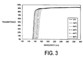
- FIGS. 1 to 3 graphs of transmission characteristics of various materials in the ultraviolet region, where the wavelength is 300 nm or less, are shown in FIGS. 1 to 3 .
- FIG. 1 depicts the transmission characteristics of calcium fluoride (CaF 2 )
- FIG. 2 depicts the transmission characteristics of crystal (crystalline state)
- FIG. 3 depicts the transmission characteristics of quartz glass.
- the thickness of each measured material is 10 mm.
- wavelength is shown on the horizontal axis and transmittance is shown on the vertical axis. Transmission characteristics at each of the temperatures shifted in a range from 18°C (room temperature) to 500°C are plotted in the figures. In these transmission characteristics, the wavelength on the short wavelength side where the transmittance decreases rapidly is the absorption edge wavelength.
- the absorption edge wavelength of calcium fluoride is about 122 nm at temperature conditions of room temperature levels (18°C). It is clear from the figures that the absorption edge wavelength shifts to the long wavelength side as the temperature of the ultraviolet light transmittance material rises. A detailed description will be given later, but a linear proportional relationship exists between the temperature of the ultraviolet light transmittance member and the absorption edge wavelength and, by detecting the absorption edge wavelength, the temperature of the ultraviolet light transmittance member can be derived from the absorption edge wavelength. Additionally, due to the fact that the transmittance of ultraviolet light changes depending on the thickness of the member, the transmission characteristics, the relationship between the temperature and the absorption edge wavelength, and the like depicted in FIGS. 1 to 3 are set according to the thickness of the ultraviolet light transmittance member that is used.
- a second aspect exemplifying the present invention is a temperature measurement device for measuring a temperature of an ultraviolet light transmittance member transmitting ultraviolet light (for example, the housing 13 or the ultraviolet light transmittance member 45 in the embodiments).
- This temperature measurement device includes a spectroscopic measurement unit for detecting an intensity distribution of a wavelength region including an absorption edge wavelength of an ultraviolet light transmittance member, in ultraviolet light transmitted through the ultraviolet light transmittance member; and a calculation processing unit for obtaining the absorption edge wavelength of the ultraviolet light transmittance member from the intensity distribution of the ultraviolet light detected by the spectroscopic measurement unit, and deriving a temperature of the ultraviolet light transmittance member on the basis of the obtained absorption edge wavelength.
- a third aspect exemplifying the present invention is a light source device.
- This light source device includes a light source unit for generating ultraviolet light; an ultraviolet light transmittance member (e.g. the housing 13 in the embodiments) that transmits the ultraviolet light generated by the light source unit; and the temperature measurement device for the ultraviolet light transmittance member of the second aspect.
- the temperature measurement device includes an alert control unit for performing alert operations in a case that a derived temperature of the ultraviolet light transmittance member becomes greater than or equal to a preset reference value.
- a fourth aspect exemplifying the present invention is a light source device.
- This light source device includes a light source unit for generating ultraviolet light; an ultraviolet light transmittance member (e.g. the housing 13 in the embodiments) that transmits the ultraviolet light generated by the light source unit; a spectroscopic measurement unit for detecting an intensity of light which is included in the ultraviolet light and which has an absorption edge wavelength of the ultraviolet light transmittance member, the absorption edge wavelength being an absorption edge wavelength in a case that the ultraviolet light transmittance member through which the ultraviolet light has passed becomes equal to a reference temperature; and an alert control unit for performing alert operations when the intensity of the light detected by the spectroscopic measurement unit becomes less than or equal to a preset reference value.
- a fifth aspect exemplifying the present invention is a temperature measurement device for measuring a temperature of an ultraviolet light transmittance member (for example, the ultraviolet light transmittance member 45 in the embodiments) transmitting a first ultraviolet light.
- This temperature measurement device includes a light source unit for generating a second ultraviolet light, a spectroscopic measurement unit for detecting an intensity distribution of a wavelength region including an absorption edge wavelength of the ultraviolet light transmittance member, in the second ultraviolet light generated by the light source unit and transmitted through the ultraviolet light transmittance member; and a calculation processing unit for obtaining the absorption edge wavelength of the ultraviolet light transmittance member from the intensity distribution of the second ultraviolet light detected by the spectroscopic measurement unit, and deriving a temperature of the ultraviolet light transmittance member on the basis of the obtained absorption edge wavelength.
- ultraviolet light transmitted through the ultraviolet light transmittance member is detected using the spectroscopic measurement unit, and the absorption edge wavelength is obtained; and the temperature of the ultraviolet light transmittance member is derived on the basis of the obtained absorption edge wavelength.
- the temperature of the ultraviolet light transmittance member can be accurately measured by concise means.
- the temperature measurement device of the second aspect includes the spectroscopic measurement unit for detecting the intensity distribution of the ultraviolet light transmitted through the ultraviolet light transmittance member; and the calculation processing unit for obtaining the absorption edge wavelength of the ultraviolet light transmittance member from the intensity distribution of the ultraviolet light, and deriving the temperature of the ultraviolet light transmittance member on the basis of the obtained absorption edge wavelength.
- the light source device of the third aspect includes the light source unit for generating ultraviolet light; the ultraviolet light transmittance member that transmits ultraviolet light generated by the light source unit; and the temperature measurement device for the ultraviolet light transmittance member of the second aspect.
- the temperature measurement device includes the alert control unit for performing alert operations (operations for alerting a user or the like of danger, operations for preventing a device from reaching a state of danger, operations for extricating a device from a state of danger, and the like) when the derived temperature of the ultraviolet light transmittance member becomes greater than or equal to a preset reference value.
- alert operations is a concept including visual alerts that perform alarm displays via a rotating lamp, a liquid crystal display screen, or the like; audio alerts that produce alarm sounds via a speaker or the like; active control alerts that reduce the light intensity of ultraviolet light generated by a light source unit or increase cooling capacity of a cooling structure for an ultraviolet light transmittance member; and the like.
- a light source device by which the occurrence of problems caused by temperature increases of the ultraviolet light transmittance member can be prevented, can be provided with a concise device configuration.
- the light source device of the fourth aspect includes the light source unit for generating ultraviolet light; the ultraviolet light transmittance member that transmits the ultraviolet light generated by the light source unit; the spectroscopic measurement unit for detecting the intensity of light which is included in the ultraviolet light and which has the absorption edge wavelength of the ultraviolet light transmittance member, the absorption edge wavelength being an absorption edge wavelength in a case that the ultraviolet light transmittance member through which the ultraviolet light has passed becomes equal to the reference temperature; and the alarm control unit for performing alarm operations when the intensity of the light detected by the spectroscopic measurement unit becomes less than or equal to the preset reference value.
- the temperature measurement device of the fifth aspect is a temperature measurement device for measuring the temperature of an ultraviolet light transmittance member transmitting a first ultraviolet light.
- the temperature measurement device includes the light source unit for generating the second ultraviolet light (e.g. a second light source unit 42 in the embodiments), the spectroscopic measurement unit for detecting the intensity distribution of the wavelength region including the absorption edge wavelength of the ultraviolet light transmittance member, in the second ultraviolet light generated by the light source unit and transmitted through the ultraviolet light transmittance member; and the calculation processing unit for obtaining the absorption edge wavelength of the ultraviolet light transmittance member from the intensity distribution of the second ultraviolet light detected by the spectroscopic measurement unit, and deriving the temperature of the ultraviolet light transmittance member on the basis of the obtained absorption edge wavelength.
- a temperature measurement device by which the temperature of the ultraviolet light transmittance member can be accurately measured, can be provided with a concise configuration.
- FIG. 4 depicts a summary configuration diagram of a light source device LS1 including a temperature measurement device for measuring the temperature of an ultraviolet light transmittance member (an ultraviolet light transmitting member; an ultraviolet light transmission member); and
- FIG. 5 depicts a schematic diagram of a light source of the light source device LS1.
- a configuration is provided in which a deuterium lamp is used as an example of a light source for generating ultraviolet light, and a calcium fluoride tube is used as the housing (also referred to as "chamber”, "bulb”, or the like) of the deuterium lamp.
- the light source device LS1 includes a light source 1 for generating ultraviolet light of a spectrum in the vacuum ultraviolet region, and a temperature measurement device 2 for measuring the temperature of the housing of the deuterium lamp in the light source 1.
- the light source 1 includes a deuterium lamp (D 2 lamp) 10, and a lamp power source 15 for supplying electrical power to the deuterium lamp 10.
- the deuterium lamp 10 is constituted from an anode 11, a cathode 12, and a housing 13.
- a cylindrical tube formed from calcium fluoride (CaF 2 ) as a raw material is machined and molded into the housing 13.
- the deuterium lamp 10 is configured such that the anode 11 and the cathode 12 are fused at both ends of the housing 13, separated by a predetermined gap, and an interior of the housing 13 is filled with deuterium gas.
- the lamp power source 15 is electrically connected to the anode 11 and the cathode 12, and DC electrical power is supplied to the anode 11 and the cathode 12 from the lamp power source 15.
- DC electrical power is supplied, electrical discharge occurs between the anode 11 and the cathode 12, the plasma of the deuterium excited by the electrical discharge emits light, and ultraviolet light UV1 of a spectrum in the vacuum ultraviolet region is generated.
- the electrical discharge region between the anode 11 and the cathode 12 corresponds to a light source portion 14 of the deuterium lamp 10.
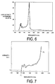
- An example of an emission spectrum of the ultraviolet light UV1 generated by the light source portion 14 is depicted in FIG. 6 . In FIG.
- wavelength is shown on the horizontal axis and normalized light intensity (light output) is shown on the vertical axis. From FIG. 6 , it is clear that the emission spectrum of the deuterium lamp 10 has a strong peak (emission line) near 160 nm, and that the emission band extends up to regions less than or equal to 120 nm on the side of shorter wavelengths.
- the ultraviolet light UV1 generated by the light source portion 14 transmits through the ultraviolet light transmittance member, namely the housing 13, and exits the deuterium lamp 10.
- the ultraviolet light UV1 that has exited from the deuterium lamp 10 is collected and collimated by a parabolic mirror or similar condensing member 18, and then output from the light source device LS1.
- a portion (e.g. about a few percent) of the ultraviolet light UV1 that has been output from the light source device LS1 is split off by a beam splitter 19 and enters the temperature measurement device 2.
- the temperature measurement device 2 includes a spectroscopic measurement unit 20 for detecting the intensity distribution (spectrum or spectral intensity distribution) of the ultraviolet light UV1 split off by the beam splitter 19; and a calculation processing unit 25 for obtaining the absorption edge wavelength of the housing 13 from the intensity distribution of the ultraviolet light, and deriving the temperature of the housing 13 on the basis of the obtained absorption edge wavelength.
- a spectroscopic measurement unit 20 for detecting the intensity distribution (spectrum or spectral intensity distribution) of the ultraviolet light UV1 split off by the beam splitter 19
- a calculation processing unit 25 for obtaining the absorption edge wavelength of the housing 13 from the intensity distribution of the ultraviolet light, and deriving the temperature of the housing 13 on the basis of the obtained absorption edge wavelength.
- the spectroscopic measurement unit 20 includes a spectral separation member 21 for spectrally separating the ultraviolet light UV1, and an intensity distribution detector 22 for detecting the intensity distribution of the ultraviolet light UV1 spectrally-separated by the spectral separation member 21.
- Examples of the spectral separation member 21 for spectrally separating the ultraviolet light UV1 include diffraction gratings formed from a metal material that reflects light of the wavelength band of the ultraviolet light UV1, prisms formed from an ultraviolet light transmittance material through which light of the wavelength band of the ultraviolet light UV1 passes, and the like.
- FIG. 4 illustrates a configuration in which a diffraction grating is used.
- Examples of the intensity distribution detector 22 include photodiode arrays and photomultipliers that have sensitivity to light of the wavelength band of the ultraviolet light UV1.
- FIG. 4 illustrates a configuration in which a photodiode array is used. Signals of the intensity distribution of the ultraviolet light UV1 detected by the intensity distribution detector 22 are output from the spectroscopic measurement unit 20 and input into the calculation processing unit 25.
- the calculation processing unit 25 includes a memory 26 for storing a preset temperature derivation program, characteristic data pertaining to the housing 13, and the like; a computing unit 27 for deriving the temperature of the housing 13 from the intensity distribution of the ultraviolet light UV1 detected by the spectroscopic measurement unit 20 and the characteristic data stored in the memory 26, on the basis of the temperature derivation program; and an alert control unit 28 for performing alert operations when the temperature of the housing 13 derived by the computing unit 27 becomes greater than or equal to a preset reference value.
- the temperature derivation program for deriving the temperature of the housing 13 from the characteristic data pertaining to the housing 13, the intensity distribution of the ultraviolet light UV1, and the like, is set/stored (set and/or stored) in advance in the memory 26.
- the temperature derivation program includes an absorption edge wavelength detection sub-program for obtaining the absorption edge wavelength of the housing 13 from the intensity distribution of the ultraviolet light UV1, and a wavelength temperature conversion sub-program for calculating the temperature of the housing 13 from the obtained absorption edge wavelength.
- Examples of the characteristic data pertaining to the housing 13 include the transmission characteristics of calcium fluoride such as depicted in FIG. 1 , the emission spectrum of the light source portion 14 as depicted in FIG. 6 , and the like.
- FIG. 7 depicts an explanatory diagram for explaining a method for detecting the absorption edge wavelength of Working Example 1.
- the wavelength of the light included in the ultraviolet light UV1 is shown on the horizontal axis of the graph and the intensity is shown on the vertical axis.
- An example of the intensity distribution of the ultraviolet light UV1 detected by the intensity distribution detector 22 is plotted on the graph.
- the intensity has become less than or equal to an intensity I 1 , indicated by a dashed line, near wavelength 127.5 nm.
- the intensity I 1 indicated by the dashed line in FIG. 7 is set/stored in the memory 26 as the reference value; the computing unit 27 detects a wavelength ⁇ 1 where the intensity becomes less than or equal to the reference value I 1 from the data of the intensity distribution S 1 of the ultraviolet light UV1 output from the intensity distribution detector 22; and this ⁇ 1 is defined as the absorption edge wavelength of the housing 13.
- the intensity reference value I 1 can be appropriately set to a range of about 1% to 30% of the intensity of the light of the wavelength ⁇ 1 detected in a state where the temperature is room temperature level (18°C).
- a wavelength in the intensity distribution of the ultraviolet light UV1 detected by the spectroscopic measurement unit 20 where dI/d ⁇ , that is, the slope of the intensity distribution, where ⁇ is the wavelength and I is the intensity, becomes greater than or equal to a predetermined reference value is defined to be the absorption edge wavelength of the housing 13.
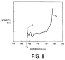
- FIG. 8 depicts an explanatory diagram for explaining this method for detecting the absorption edge wavelength. As in FIG. 7 , the wavelength of the light included in the ultraviolet light UV1 is shown on the horizontal axis and the intensity is shown on the vertical axis. An example of the intensity distribution of the ultraviolet light UV1 detected by the intensity distribution detector 22 is plotted on the graph.
- the value of dI/d ⁇ that is, the slope of the intensity distribution, near wavelength 127.5 nm indicated by the two-dot dash line rapidly increases.
- a value I', which is dI/d ⁇ , indicated by the two-dot dash line is set/stored in the memory 26 as the reference value; the computing unit 27 detects a wavelength ⁇ 2 where dI/d ⁇ becomes greater than or equal to the reference value I' from the data of the intensity distribution S 2 of the ultraviolet light UV1 output from the intensity distribution detector 22; and this ⁇ 2 is defined as the absorption edge wavelength.
- the emission spectrum (intensity distribution) of the ultraviolet light UV1 near the light source portion 14 set/stored in advance in the memory 26 is compared with the intensity distribution of the ultraviolet light UV1 that has transmitted through the housing 13 and has been detected by the spectroscopic measurement unit 20; and a wavelength where the difference is greater than or equal to a predetermined reference value is defined as the absorption edge wavelength of the housing 13.
- FIGS. 9A and 9B depict explanatory diagrams for explaining this method for detecting the absorption edge wavelength. As in FIGS. 7 and 8 , the wavelength of the light included in the ultraviolet light UV1 is shown on the horizontal axes and the intensity is shown on the vertical axes in these graphs.
- An emission spectrum S 31 of the ultraviolet light UV1 near the light source portion 14 in FIG. 9A is plotted on the graph as a two-dot dash line, and an intensity distribution S 32 of the ultraviolet light UV1 that has transmitted through the housing 13 and has been detected by the intensity distribution detector 22 is plotted on the graph as a solid line. Additionally, intensity characteristics (spectral intensity characteristics) S 3 of a difference (S 31 - S 32 ) obtained by subtracting the intensity distribution S 32 of the ultraviolet light UV1 detected by the intensity distribution detector 22 from the emission spectrum S 31 of the ultraviolet light UV1 near the light source portion 14, is plotted in FIG. 9B .
- the emission spectrum S 31 of the ultraviolet light UV1 near the light source portion 14 is the intensity distribution of the ultraviolet light UV1 prior to transmitting through the housing 13;
- the intensity distribution S 32 of the ultraviolet light UV1 detected by the intensity distribution detector 22 is the intensity distribution of the ultraviolet light UV1 after transmitting through the housing 13;
- the intensity characteristics S 3 of the difference represent the characteristics of the loss that occurs when the ultraviolet light UV1 transmitted through the housing 13.
- the fact that a region where loss is great exists in the short wavelength region means that absorption of the light having a wavelength in this region is occurring at the housing 13, and a wavelength ⁇ 3 where the difference rapidly increases is the absorption edge wavelength of the housing 13.
- Data of the emission spectrum S 31 of the light source portion 14 and a reference value D of the difference are set/stored in advance in the memory 26; the computing unit 27 detects the wavelength ⁇ 3 where the difference is greater than or equal to the reference value D from the intensity characteristics S 3 of the difference obtained by subtracting the intensity distribution S 32 of the ultraviolet light UV1 detected by the intensity distribution detector 22 from the emission spectrum S 31 of the ultraviolet light UV1 near the light source portion 14; and this wavelength ⁇ 3 is defined as the absorption edge wavelength.
- the method in which the difference (S 31 -S 32 ) between the emission spectrum S 31 and the intensity distribution S 32 was obtained was given as an example of a processing method for obtaining the difference between the emission spectrum of the ultraviolet light UV1 near the light source portion 14 and the intensity distribution of the ultraviolet light UV1 detected by the intensity distribution detector 22.
- other processing methods may be used provided that a wavelength can be obtained where the difference between the emission spectrum S 31 and the intensity distribution S 32 described above becomes greater than or equal to a reference value, less than or equal to a reference value, or equal to a reference value.
- the intensity distribution S 32 of the ultraviolet light UV1 detected by the intensity distribution detector 22 is divided by the emission spectrum S 31 of the ultraviolet light UV1 near the light source portion 14, and a wavelength is detected where the value of S 32 /S 31 is less than or equal to a reference value.
- the calculation processing unit 25 derives the temperature of the housing 13 from the absorption edge wavelength obtained as described above as follows. First, return to FIG. 1 . From this drawing, it is understood that, in cases where the material of the housing 13 is calcium fluoride (CaF 2 ), the absorption edge wavelength of the housing 13 when the temperature is 18°C (room temperature level) is approximately 122 nm. As the temperature rises, the absorption edge wavelength shifts to the long wavelength side, and at 500°C, the absorption edge wavelength is approximately 140 nm. Note that the absorption edge wavelength is defined as the wavelength where transmittance becomes less than 1%.
- FIG. 10 is a graph wherein the relationships between temperature and absorption edge wavelength in FIG. 1 are depicted in another manner. Temperature is shown on the horizontal axis of the graph and absorption edge wavelength is shown on the vertical axis (as in FIG. 1 , the absorption edge wavelength is the wavelength where transmittance becomes less than 1%).
- data for calcium fluoride which is the material of the housing 13
- regression lines obtained by the method of least squares are shown as a dot-dash line for calcium fluoride, a dashed line for crystal, and a solid line for quartz glass.
- the absorption edge wavelength is defined as the wavelength where transmittance becomes less than 1%
- the characteristics formulas are obtained with the absorption edge wavelength thus obtained.
- the absorption edge wavelength is the wavelength where the intensity of the transmitted light becomes less than or equal to a reference value
- the absorption edge wavelength is the wavelength where dI/d ⁇ becomes greater than or equal to a reference value
- the absorption edge wavelength is the wavelength where the difference between the emission spectrum of the light source unit and the ultraviolet light intensity distribution is greater than or equal to a reference value
- the temperature of the housing 13 can be derived on the basis of each characteristics formula.
- the transmittance of the ultraviolet light varies depending on the thickness of the member and, thus, the characteristics formulas may differ depending on the shape, dimensions, and the like of the measurement target, namely, the housing 13.
- the characteristics formulas are set/stored in advance in the memory 26.
- the calculation processing unit 25 derives the temperature of the housing 13 on the basis of the absorption edge wavelength of the housing 13 detected via at least one of the methods of Working Examples 1 to 3, described above. Specifically, the characteristics formulas stored in the memory 26 are read out to the computing unit 27 and, for example, an absorption edge wavelength ⁇ 1 detected via the method of Working Example 1 is substituted in and the temperature of the housing 13 is derived. Then, the calculated housing temperature is output to an operating panel or external personal computer (not illustrated in the drawings) via an I/O circuit, and displayed as the "housing temperature".
- the calculation processing unit 25 performs alert operations such as those described below.
- the reference value set/stored in the memory 26 is set in accordance with the material, shape, dimensions, and the like of the housing 13. For example, when the temperature of calcium fluoride becomes about 210°C or higher, slip begins to occur at the crystal interface, and the mechanical strength thereof declines. Accordingly, in cases such as in the present embodiment where the material of the housing 13 is calcium fluoride, a temperature of approximately 190 to 210°C (e.g. 200°C) is set/stored in the memory 26 as a reference temperature for alarm occurrence.
- the reference temperature is set to lower than 190°C, the emission intensity of the light source portion 14 may be suppressed to unnecessarily low levels or the operation rate may decline; and if the reference temperature is set to higher than 210°C, the housing 13 may be damaged.
- a temperature of approximately 380 to 420°C e.g. 400°C is set/stored in the memory 26 as the reference temperature for alert operations. This is because structural change occurs in crystal at around 450°C.
- the calculation processing unit 25 causes an alert control unit 28 to perform alert operations when the temperature of the housing 13 calculated by the computing unit 27 becomes greater than or equal to the reference temperature set/stored in the memory 26.
- alert operations is a concept including visual alerts that perform alarm displays via a rotating lamp, a liquid crystal display screen, or the like; audio alerts that produce alarm sounds via a speaker or the like; active control alerts that reduce the light intensity of the ultraviolet light UV1 generated by the light source portion 14 or strengthen cooling of the ultraviolet light transmittance member by increasing cooling capacity of a cooling structure; and the like.
- the configuration examples of Working Example 4 and Working Example 5 are given as examples of active control alerts.
- the alert control unit 28 performs alert operations to reduce the emission intensity of the ultraviolet light UV1 generated by the light source portion 14 of the deuterium lamp 10. Specifically, the alert control unit 28 outputs an alert signal to the lamp power source 15 of the deuterium lamp 10 and decreases the electrical discharge power between the anode 11 and the cathode 12, thereby reducing the emission intensity of the ultraviolet light UV1 generated by the light source portion 14. For example, the emission intensity is reduced to about 80% of the emission intensity prior to the alert occurrence. At this time, the alert control unit 28 also outputs the alert signal to an operation panel, external personal computer, or the like (not illustrated in the drawings) via the I/O circuit, and displays a message such as "emission intensity reduced to 80% due to housing temperature becoming greater than or equal to reference value". Preferably a visual alert informing of an abnormality via a rotating lamp or an audio alert such as beeping is performed, simultaneously with the active control alert.
- the alert control unit 28 performs alert operations to strengthen cooling of the housing 13 by increasing the cooling capacity of a cooling structure that cools the deuterium lamp 10.
- the light source 1 includes a cooling structure CL for cooling the deuterium lamp 10.
- a configuration in which nitrogen gas is used to shield the deuterium lamp 10 from the atmospheric environment and also for the cooling of the deuterium lamp 10 is described as an example of the cooling structure CL.
- the deuterium lamp 10 is attached within a lamp housing RH that has an airtight structure.
- a gas supply unit GS for feeding nitrogen gas is connected to the lamp housing RH and fresh nitrogen gas is constantly purged or supplied at an appropriate flow rate.
- the deuterium lamp 10 is shielded from the atmospheric environment and the housing 13 is cooled by the nitrogen gas flowing around the lamp.
- the cooling capacity of the cooling structure CL can be increased and decreased by changing the flow rate of the nitrogen gas supplied from the gas supply unit GS. That is, in this working example, the lamp housing RH and the gas supply unit GS constitute the cooling structure CL.
- the alert control unit 28 When the temperature of the housing 13 becomes higher than or equal to the reference temperature, the alert control unit 28 outputs an alert signal to the gas supply unit GS and increases the flow rate of the nitrogen gas so as to increase the cooling capacity of the cooling structure CL.
- the nitrogen gas is supplied by the gas supply unit GS at a flow rate that is increased 20% over the flow rate prior to the alert occurrence.
- the alert control unit 28 also outputs the alert signal to an operation panel, external personal computer, or the like (not illustrated in the drawings) via the I/O circuit, and displays a message such as "nitrogen gas supply amount increased 20% due to housing temperature becoming greater than or equal to reference value".
- a visual alert informing of an abnormality via a rotating lamp or an audio alert such as beeping is performed, simultaneously with the active control alert.
- the cooling capacity can be increased by increasing the flow rate of the cooling water or the like.
- the cooling structure may have a configuration in which the cooling capacity is increased by lowering the temperature of the cooling water or the like.
- the temperature of the housing 13 can be accurately measured with a concise configuration, and the occurrence of problems caused by temperature increases of the housing 13 can be prevented.
- FIG. 11 depicts a summary configuration diagram of a light source device LS2 including a temperature measurement device 3.
- the light source device LS2 of the second embodiment will be described while referring to FIG. 11 .
- the configuration of a light source 1 of the light source device LS2 is the same as that of the light source 1 of the light source device LS1. Therefore, identical constituents are marked with identical reference numerals and repeated description thereof is omitted; and the temperature measurement device 3 that differs from the temperature measurement device 2 is described in detail.
- the light source device LS2 mainly includes a light source 1, that includes a deuterium lamp 10, for generating ultraviolet light UV1 of a spectrum in the vacuum ultraviolet region; and a temperature measurement device 3 for detecting when the temperature of the housing 13 of the deuterium lamp 10 becomes greater than or equal to a preset reference value, and performing alert operations.
- the temperature measurement device 3 includes a spectroscopic measurement unit 30 for spectrally separating the ultraviolet light UV1 split off by the beam splitter 19 and detecting the intensity of light of a predetermined wavelength; and a calculation processing unit 35 for determining whether or not the intensity of the light detected by the spectroscopic measurement unit 30 is less than or equal to a reference value.
- the spectroscopic measurement unit 30 includes a spectral separation member 31 for spectrally separating the ultraviolet light UV1, and a spectral detector 32 for detecting the intensity of light of a predetermined wavelength from among the light spectrally-separated by the spectral separation member 31.
- a configuration is depicted in FIG. 11 in which a diffraction grating is used as the spectral separation member 31; and an aperture plate 32a provided with an aperture at a position corresponding to a predetermined wavelength of the spectrally-separated light, and a photodiode 32b arranged on a backside (below in FIG. 11 ) of the aperture are used as the spectral detector 32 for detecting the intensity of light of the predetermined wavelength.
- the predetermined wavelength described above is the absorption edge wavelength of the housing 13 when the temperature of the housing 13 is equal to a reference temperature.
- the reference temperature is a temperature at which further use of the housing 13 at a temperature range above the reference temperature should be prevented; and, in cases where the material of the housing 13 is calcium fluoride, is set to about 190 to 210°C, for example, to 200°C.
- the absorption edge wavelength when the temperature of calcium fluoride becomes 200°C (the wavelength where the transmittance becomes less than 1% is used as the absorption edge wavelength) is approximately 127.5 nm, as depicted in FIG. 10 .
- the aperture of the aperture plate 32a is set to the position of the 127.5 nm wavelength and the intensity of light at this wavelength is detected by the photodiode 32b.
- the intensity of the light at the 127.5 nm wavelength detected by the photodiode 32b becoming less than or equal to a reference value means that the temperature of the housing 13 has become higher than or equal to the 200°C reference temperature.
- Signals of the light intensity of the absorption edge wavelength of the housing 13 detected by the spectral detector 32 are output from the spectroscopic measurement unit 30 and input into the calculation processing unit 35.
- the calculation processing unit 35 includes a memory 36 for storing the preset reference value described above; a computing unit 37 for comparing the intensity of the light detected by the spectroscopic measurement unit 30 with the reference value set in the memory 36, and determining whether or not the light intensity is less than or equal to the reference value; and an alert control unit 38 for performing alert operations when the computing unit 37 determines that the intensity of the light detected by the spectroscopic measurement unit 30 has become less than or equal to the reference value.
- the calculation processing unit 35 causes the alert control unit 38 to perform alert operations when the computing unit 37 determines that the intensity of the light detected by the spectroscopic measurement unit 30 has become less than or equal to the reference value set in the memory 36.
- the specific control details of the alert operations executed by the alert control unit 38 are the same as the control details of the alert control unit 28 described previously in Working Examples 4 and 5 of the first embodiment.
- the temperature of the housing 13 can be accurately measured with a concise and inexpensive device configuration, and the occurrence of problems caused by temperature increases of the housing 13 can be prevented.
- a predetermined reference value may be set such that the intensity of the light at the 127.5 nm wavelength detected by the photodiode 32b becoming equal to the predetermined reference value, or the difference between the intensity of the light at the 127.5 nm wavelength and the predetermined reference value becoming less than or equal to the predetermined value means that the temperature of the housing 13 has become higher than or equal to the 200°C reference temperature.
- the intensity of the light detected by the spectroscopic measurement unit 30 and the reference value set in the memory 36 may be compared and whether or not the light intensity is less than or equal to the reference value may be determined in the alert control unit 38 instead of the computing unit 37.
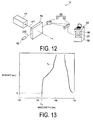
- FIG. 12 depicts a schematic diagram of a temperature measurement device 5.
- the temperature measurement device 5 is a temperature measurement device for measuring a temperature of an ultraviolet light transmittance member 45 such as a window, a lens, or optical wavelength conversion element, through which a first ultraviolet light LV1, which has exited from a first light source unit 41, transmits.
- an ultraviolet light transmittance member 45 such as a window, a lens, or optical wavelength conversion element
- This temperature measurement device 5 includes a second light source unit 42 for generating a second ultraviolet light LV2 having a spectrum in the vacuum ultraviolet region, a spectroscopic measurement unit 50 for detecting an intensity distribution of the second ultraviolet light LV2 generated by the second light source unit 42 and transmitted through the ultraviolet light transmittance member 45; and a calculation processing unit 55 for obtaining an absorption edge wavelength of the ultraviolet light transmittance member 45 from the intensity distribution of the second ultraviolet light LV2 detected by the spectroscopic measurement unit 50, and deriving a temperature of the ultraviolet light transmittance member 45 on the basis of the obtained absorption edge wavelength.
- the first light source 41 is an ArF excimer laser or an F 2 laser, or an all-solid-state laser device that outputs laser light having the same wavelength as an ArF excimer laser or an F 2 laser (e.g. see Japanese Unexamined Patent Application Publication No. 2005-275095 , by the applicant of the present application, and the like).
- the first ultraviolet light LV1 is light having a wavelength of 193 nm or 157 nm, and having high monochromaticity.
- the first ultraviolet light LV1 is not limited to these types of laser light and may be ultraviolet light of a predetermined spectrum width. In this embodiment, description is given for a case in which crystal (crystalline state) is used as the ultraviolet light transmittance member 45 that transmits ultraviolet light of these wavelength bands.
- the second ultraviolet light LV2 is light having a spectrum (intensity distribution) in a wavelength region including the absorption edge wavelength of the ultraviolet light transmittance member 45.
- the second ultraviolet light LV2 is light having a spectrum in a wavelength region including the absorption edge wavelength of crystal, namely, 145 to 155 nm.
- Examples of the second light source 42 for generating the second ultraviolet light LV2 include the previously described deuterium lamp 10.
- the spectroscopic measurement unit 50 includes a spectral separation member 51 for spectrally separating the second ultraviolet light LV2, and an intensity distribution detector 52 for detecting the intensity distribution of the second ultraviolet light LV2 spectrally-separated by the spectral separation member 51.
- the spectral separation member 51 include diffraction gratings and prisms
- the intensity distribution detector 52 include photodiode arrays and photomultipliers.
- FIG. 12 illustrates a configuration in which a diffraction grating is used as the spectral separation member 51 and a photodiode array is used as the intensity distribution detector 42. Signals of the intensity distribution of the second ultraviolet light LV2 detected by the intensity distribution detector 52 are output from the spectroscopic measurement unit 50 and input into the calculation processing unit 55.
- the calculation processing unit 55 includes a memory 56 for storing a preset temperature derivation program, characteristic data pertaining to the ultraviolet light transmittance member 45, and the like; a computing unit 57 for deriving a temperature of the ultraviolet light transmittance member 45 from an intensity distribution of the second ultraviolet light LV2 detected by the spectroscopic measurement unit 50 and the characteristic data stored in the memory 56, on the basis of the temperature derivation program; and an alert control unit 58 for performing alert operations when the temperature of the ultraviolet light transmittance member 45 derived by the computing unit 57 becomes greater than or equal to a preset reference value.
- the temperature derivation program and the like for deriving the temperature of the ultraviolet light transmittance member 45 from the characteristic data pertaining to the ultraviolet light transmittance member 45 and the intensity distribution of the second ultraviolet light LV2, is set/stored in advance in the memory 56.
- the temperature derivation program includes an absorption edge wavelength detection sub-program for obtaining the absorption edge wavelength of the ultraviolet light transmittance member 45 from the intensity distribution of the second ultraviolet light LV2, and a wavelength temperature conversion sub-program for calculating the temperature of the ultraviolet light transmittance member 45 from the obtained absorption edge wavelength.
- examples of the characteristic data pertaining to the ultraviolet light transmittance member 45 include the transmission characteristics of crystal depicted in FIG. 2 , the emission spectrum of the second light source unit 42 depicted in FIG. 6 , and the like (however, FIG. 6 does not depict the emission spectrum of the second light source unit 42 itself, but rather depicts the emission spectrum of the deuterium lamp 10 including the housing, which has a structure identical to the second light source unit 42).
- the method for deriving the temperature of the ultraviolet light transmittance member 45 by the calculation processing unit 55 is the same as the method for deriving the temperature of the housing 13 by the calculation processing unit 25 of the first embodiment described above (Working Examples 1 to 3). As such, a simple description is given here of a case in which the method for deriving the temperature of Working Example 1 is applied as the method for deriving the temperature of the ultraviolet light transmittance member 45 by the calculation processing unit 55.
- a wavelength where the intensity becomes less than or equal to a predetermined reference value in the intensity distribution of the second ultraviolet light LV2 detected by the spectroscopic measurement unit 50 is defined as the absorption edge wavelength of the ultraviolet light transmittance member 45.
- the wavelength of the light included in the second ultraviolet light LV is shown on the horizontal axis and the intensity is shown on the vertical axis.
- An example of the intensity distribution of the second ultraviolet light LV2 detected by the intensity distribution detector 52 is plotted on the graph.
- the intensity I 4 indicated by the dashed line is set/stored in the memory 56 as the reference value; the computing unit 57 detects a wavelength ⁇ 4 where the intensity becomes less than or equal to the reference value I 4 , from the data of the intensity distribution S 4 of the second ultraviolet light LV2 output from the intensity distribution detector 52; and this ⁇ 4 is defined as the absorption edge wavelength of the ultraviolet light transmittance member 45.
- the calculation processing unit 55 derives the temperature of the ultraviolet light transmittance member 45 on the basis of the characteristics formula of the ultraviolet light transmittance member 45 set/stored in advance and the detected absorption edge wavelength ⁇ 4 .
- the calculation processing unit 55 reads out the characteristics formula of crystal (see FIG. 10 for an example) stored in the memory 56 to the computing unit 57, and the temperature of the ultraviolet light transmittance member 45 is derived by substituting the absorption edge wavelength ⁇ 4 into the read-out characteristics formula. For example, if ⁇ 4 is 153 nm, the temperature of the ultraviolet light transmittance member 45 calculated from the characteristics formula of crystal is 300°C.
- the calculation processing unit 55 outputs the calculated temperature of the ultraviolet light transmittance member 45 to an operating panel or external personal computer (not illustrated in the drawings) via an I/O circuit, and displays the temperature as "ultraviolet light transmittance member temperature".
- the calculation processing unit 55 performs predetermined alert operations.
- the reference value set/stored in the memory 56 is set basically in accordance with the material, shape, dimensions, and the like of the ultraviolet light transmittance member 45, and the wavelength of the first ultraviolet light LV1 that transmits through the ultraviolet light transmittance member 45.
- the material of the ultraviolet light transmittance member 45 is crystal as in this embodiment, structural change occurs in crystal at around 450°C, and the physical and mechanical characteristics thereof change.
- the reference temperature for alarm occurrence is set on the basis of this temperature (450°C).
- the reference temperature for alert operations is set to a temperature of about 380 to 420°C (e.g. 400°C), and is set/stored in the memory 56.
- the wavelength difference (margin) must be taken into consideration.
- the absorption edge wavelength of the ultraviolet light transmittance member 45 at the reference temperature will be 156 nm.
- the wavelength difference between the absorption edge wavelength of the ultraviolet light transmittance member 45 and the wavelength of the first ultraviolet light LV1, namely 157 nm will be about 1 nm.
- a wavelength difference of a set magnitude is provided between the wavelength of the first ultraviolet light LV1 and the absorption edge wavelength of the ultraviolet light transmittance member 45 at the reference temperature, and the reference temperature for the alert operations is set to a temperature of about 300 to 340°C (e.g. 320°C).
- the absorption edge wavelength of the ultraviolet light transmittance member 45 at 320°C is about 153 nm.
- the calculation processing unit 55 causes an alert control unit 58 to perform alert operations when the temperature of the ultraviolet light transmittance member 45 calculated by the computing unit 57 becomes greater than or equal to the reference temperature set/stored in the memory 56. Specific details of the alert operations are as described above. Specifically, for example, the calculation processing unit 55 outputs an alert signal to an operation panel, external personal computer, or the like (not illustrated in the drawings) via an I/O circuit, and causes a message such as, "ultraviolet light transmittance member has reached reference temperature" to be displayed, or a visual alert by means of a rotating lamp or the like or audio alert by means of beeping sounds or the like to be performed.
- the temperature of the ultraviolet light transmittance member 45 can be accurately measured with a concise configuration. Additionally, countermeasures are taken such as reducing the output of the first light source 41 on the basis of the alert operations by the alert control unit 58 and, as a result, the occurrence of problems caused by temperature increases of the ultraviolet light transmittance member 45 can be prevented.
- the temperature measurement devices 2, 3, and 5 and the light source devices LS1 and LS2 detect the ultraviolet light transmitted through the ultraviolet light transmittance member using the spectroscopic measurement unit, obtain the absorption edge wavelength of the ultraviolet light transmittance member, and derive the temperature of the ultraviolet light transmittance member on the basis of the obtained absorption edge wavelength.
- the temperature of the ultraviolet light transmittance member can be accurately measured by concise means and with a concise configuration.
- a deuterium lamp has been described as an example of a light source for generating ultraviolet light in the vacuum ultraviolet region, but any light source may be used provided that it has an emission spectrum in the vacuum ultraviolet region. Examples thereof include excimer lamps and the like. Additionally, calcium fluoride (CaF 2 ), crystal, and quartz glass (SiO 2 ) have been described as examples of the material of the ultraviolet light transmittance member through which ultraviolet light in the vacuum ultraviolet region transmits, but the present invention is not limited to these materials. The present invention may be applied likewise to other known materials that transmit ultraviolet light in the vacuum ultraviolet region such as magnesium fluoride (MgF 2 ), lithium fluoride (LiF), sapphire glass, and the same beneficial effects can be obtained.
- MgF 2 magnesium fluoride
- LiF lithium fluoride
- the calculation processing units 25 and 55 cause the alert control units 28 and 58 to perform the alert operations when the temperature of the housing 13 and the ultraviolet light transmittance member 45 become higher than or equal to the reference temperature, but the present invention is not limited to this configuration.
- the calculation processing units 25 and 55 may be configured to cause the alert control units 28 and 58 to perform the alert operations when the temperature of the housing 13 or the ultraviolet light transmittance member 45 becomes equal to the reference temperature or becomes close to the reference temperature.
Landscapes
- Physics & Mathematics (AREA)
- General Physics & Mathematics (AREA)
- Spectroscopy & Molecular Physics (AREA)
- Photometry And Measurement Of Optical Pulse Characteristics (AREA)
- Investigating Or Analysing Materials By Optical Means (AREA)
- Measuring Temperature Or Quantity Of Heat (AREA)
- Spectrometry And Color Measurement (AREA)
Abstract
Description
- The present invention relates to a temperature measurement method for measuring the temperature of an ultraviolet light transmittance member transmitting ultraviolet light, a temperature measurement device for an ultraviolet light transmittance member, and a light source device.
- Use has increased for vacuum ultraviolet (VUV) light having a wavelength of 200 nm or less as: light sources of semiconductor exposure devices and liquid crystal exposure devices, and light sources of inspection apparatuses for masks used in these exposure devices and various substrates fabricated by these exposure devices. For example, a semiconductor exposure device utilizing an ArF excimer laser having an oscillation wavelength of 193 nm as a light source is already in practical use; and furthermore, research into a light source device that produces VUV light having the same 157 nm wavelength as an F2 laser and research into a light source device using a deuterium lamp having a high-intensity peak near the 160 nm wavelength is being earnestly pursued (e.g. see Patent Literature 1).
- Calcium fluoride (CaF2: fluorite), magnesium fluoride (MgF2), crystal (SiO2), quartz (SiO2), and the like are known as materials that transmit ultraviolet light that has a wavelength in the region of 200 nm or less; and containers of lamps, windows, and other ultraviolet light transmittance members are manufactured using these materials (e.g. see
Patent Literature 2,Patent Literature 3, and Patent Literature 4). -
- Patent Literature 1:
Japanese Unexamined Patent Application Publication No. 2005-275095A - Patent Literature 2:
Japanese Unexamined Patent Application Publication No. 2009-163965A - Patent Literature 3:
Japanese Unexamined Patent Application Publication No. 2009-532829A - Patent Literature 4:
Japanese Unexamined Patent Application Publication No. 2012-79584A - When an ultraviolet light transmittance member is used as the container of a lamp, high-pressure gas is encapsulated in the container. Due to electrical discharge between electrodes or laser irradiation and the like being applied to the gas in order to generate plasma and induce light emission, the temperature of the ultraviolet light transmittance member readily rises to high temperatures. However, when the temperature of an ultraviolet light transmittance member rises to high temperatures, typically mechanical strength declines. Particularly, when the temperature of calcium fluoride (CaF2) becomes about 210°C, slip begins to occur at the crystal interface, and at even higher temperatures, the mechanical strength thereof declines significantly. In order to prevent problems of damage and the like caused by decreases in mechanical strength, the temperature of the ultraviolet light transmittance member must first be detected.
- One technique for non-contact measuring the temperature of a member is a temperature measurement device known as thermovision or thermography in which the radiation energy of infrared light emitted from a subject is detected and visualized. However, the temperature of the ultraviolet light transmittance member itself cannot be measured by thermovision or the like because all of the materials mentioned above, including the calcium fluoride, have high transmittance throughout a wide range from the vacuum ultraviolet region to the infrared region, and are transparent even in the infrared region. Contact temperature measurement using a thermocouple or the like is not preferable because the fixing member by which the thermocouple or the like is fixed to the ultraviolet light transmittance member will block the exiting of light from the plasma out of the ultraviolet light transmittance member and, in cases when plasma is generated by laser excitation, will block the entering of laser light into the ultraviolet light transmittance member.
- In light of the forgoing, an object of the present invention is to provide a temperature measurement method, a temperature measurement device, and a light source device whereby the temperature of an ultraviolet light transmittance member can be accurately measured by concise means.
- A first aspect exemplifying the present invention is a temperature measurement method for measuring the temperature of an ultraviolet light transmittance member transmitting ultraviolet light (for example, a
housing 13 or an ultravioletlight transmittance member 45 in the embodiments). This temperature measurement method is characterized by detecting ultraviolet light transmitted through the ultraviolet light transmittance member using a spectroscopic measurement unit, obtaining an absorption edge wavelength of the transmittance member, and deriving a temperature of the ultraviolet light transmittance member on the basis of the obtained absorption edge wavelength. - Here, graphs of transmission characteristics of various materials in the ultraviolet region, where the wavelength is 300 nm or less, are shown in
FIGS. 1 to 3 .FIG. 1 depicts the transmission characteristics of calcium fluoride (CaF2),FIG. 2 depicts the transmission characteristics of crystal (crystalline state), andFIG. 3 depicts the transmission characteristics of quartz glass. The thickness of each measured material is 10 mm. In each graph, wavelength is shown on the horizontal axis and transmittance is shown on the vertical axis. Transmission characteristics at each of the temperatures shifted in a range from 18°C (room temperature) to 500°C are plotted in the figures. In these transmission characteristics, the wavelength on the short wavelength side where the transmittance decreases rapidly is the absorption edge wavelength. For example, the absorption edge wavelength of calcium fluoride is about 122 nm at temperature conditions of room temperature levels (18°C). It is clear from the figures that the absorption edge wavelength shifts to the long wavelength side as the temperature of the ultraviolet light transmittance material rises. A detailed description will be given later, but a linear proportional relationship exists between the temperature of the ultraviolet light transmittance member and the absorption edge wavelength and, by detecting the absorption edge wavelength, the temperature of the ultraviolet light transmittance member can be derived from the absorption edge wavelength. Additionally, due to the fact that the transmittance of ultraviolet light changes depending on the thickness of the member, the transmission characteristics, the relationship between the temperature and the absorption edge wavelength, and the like depicted inFIGS. 1 to 3 are set according to the thickness of the ultraviolet light transmittance member that is used. - A second aspect exemplifying the present invention is a temperature measurement device for measuring a temperature of an ultraviolet light transmittance member transmitting ultraviolet light (for example, the
housing 13 or the ultravioletlight transmittance member 45 in the embodiments). This temperature measurement device includes a spectroscopic measurement unit for detecting an intensity distribution of a wavelength region including an absorption edge wavelength of an ultraviolet light transmittance member, in ultraviolet light transmitted through the ultraviolet light transmittance member; and a calculation processing unit for obtaining the absorption edge wavelength of the ultraviolet light transmittance member from the intensity distribution of the ultraviolet light detected by the spectroscopic measurement unit, and deriving a temperature of the ultraviolet light transmittance member on the basis of the obtained absorption edge wavelength. - A third aspect exemplifying the present invention is a light source device. This light source device includes a light source unit for generating ultraviolet light; an ultraviolet light transmittance member (e.g. the
housing 13 in the embodiments) that transmits the ultraviolet light generated by the light source unit; and the temperature measurement device for the ultraviolet light transmittance member of the second aspect. The temperature measurement device includes an alert control unit for performing alert operations in a case that a derived temperature of the ultraviolet light transmittance member becomes greater than or equal to a preset reference value. - A fourth aspect exemplifying the present invention is a light source device. This light source device includes a light source unit for generating ultraviolet light; an ultraviolet light transmittance member (e.g. the
housing 13 in the embodiments) that transmits the ultraviolet light generated by the light source unit; a spectroscopic measurement unit for detecting an intensity of light which is included in the ultraviolet light and which has an absorption edge wavelength of the ultraviolet light transmittance member, the absorption edge wavelength being an absorption edge wavelength in a case that the ultraviolet light transmittance member through which the ultraviolet light has passed becomes equal to a reference temperature; and an alert control unit for performing alert operations when the intensity of the light detected by the spectroscopic measurement unit becomes less than or equal to a preset reference value. - A fifth aspect exemplifying the present invention is a temperature measurement device for measuring a temperature of an ultraviolet light transmittance member (for example, the ultraviolet
light transmittance member 45 in the embodiments) transmitting a first ultraviolet light. This temperature measurement device includes a light source unit for generating a second ultraviolet light, a spectroscopic measurement unit for detecting an intensity distribution of a wavelength region including an absorption edge wavelength of the ultraviolet light transmittance member, in the second ultraviolet light generated by the light source unit and transmitted through the ultraviolet light transmittance member; and a calculation processing unit for obtaining the absorption edge wavelength of the ultraviolet light transmittance member from the intensity distribution of the second ultraviolet light detected by the spectroscopic measurement unit, and deriving a temperature of the ultraviolet light transmittance member on the basis of the obtained absorption edge wavelength. - In the temperature measurement method of the first aspect, ultraviolet light transmitted through the ultraviolet light transmittance member is detected using the spectroscopic measurement unit, and the absorption edge wavelength is obtained; and the temperature of the ultraviolet light transmittance member is derived on the basis of the obtained absorption edge wavelength. As a result, the temperature of the ultraviolet light transmittance member can be accurately measured by concise means.
- The temperature measurement device of the second aspect includes the spectroscopic measurement unit for detecting the intensity distribution of the ultraviolet light transmitted through the ultraviolet light transmittance member; and the calculation processing unit for obtaining the absorption edge wavelength of the ultraviolet light transmittance member from the intensity distribution of the ultraviolet light, and deriving the temperature of the ultraviolet light transmittance member on the basis of the obtained absorption edge wavelength. As a result, a temperature measurement device, by which the temperature of the ultraviolet light transmittance member can be accurately measured, can be provided with a concise configuration.
- The light source device of the third aspect includes the light source unit for generating ultraviolet light; the ultraviolet light transmittance member that transmits ultraviolet light generated by the light source unit; and the temperature measurement device for the ultraviolet light transmittance member of the second aspect. The temperature measurement device includes the alert control unit for performing alert operations (operations for alerting a user or the like of danger, operations for preventing a device from reaching a state of danger, operations for extricating a device from a state of danger, and the like) when the derived temperature of the ultraviolet light transmittance member becomes greater than or equal to a preset reference value. In the present specification, "alert operations" is a concept including visual alerts that perform alarm displays via a rotating lamp, a liquid crystal display screen, or the like; audio alerts that produce alarm sounds via a speaker or the like; active control alerts that reduce the light intensity of ultraviolet light generated by a light source unit or increase cooling capacity of a cooling structure for an ultraviolet light transmittance member; and the like. As a result, a light source device, by which the occurrence of problems caused by temperature increases of the ultraviolet light transmittance member can be prevented, can be provided with a concise device configuration.
- The light source device of the fourth aspect includes the light source unit for generating ultraviolet light; the ultraviolet light transmittance member that transmits the ultraviolet light generated by the light source unit; the spectroscopic measurement unit for detecting the intensity of light which is included in the ultraviolet light and which has the absorption edge wavelength of the ultraviolet light transmittance member, the absorption edge wavelength being an absorption edge wavelength in a case that the ultraviolet light transmittance member through which the ultraviolet light has passed becomes equal to the reference temperature; and the alarm control unit for performing alarm operations when the intensity of the light detected by the spectroscopic measurement unit becomes less than or equal to the preset reference value. As a result, a light source device, by which the occurrence of problems caused by temperature increases of an ultraviolet light transmittance member can be prevented, can be provided with a concise and inexpensive device configuration.
- The temperature measurement device of the fifth aspect is a temperature measurement device for measuring the temperature of an ultraviolet light transmittance member transmitting a first ultraviolet light. The temperature measurement device includes the light source unit for generating the second ultraviolet light (e.g. a second
light source unit 42 in the embodiments), the spectroscopic measurement unit for detecting the intensity distribution of the wavelength region including the absorption edge wavelength of the ultraviolet light transmittance member, in the second ultraviolet light generated by the light source unit and transmitted through the ultraviolet light transmittance member; and the calculation processing unit for obtaining the absorption edge wavelength of the ultraviolet light transmittance member from the intensity distribution of the second ultraviolet light detected by the spectroscopic measurement unit, and deriving the temperature of the ultraviolet light transmittance member on the basis of the obtained absorption edge wavelength. As a result, a temperature measurement device, by which the temperature of the ultraviolet light transmittance member can be accurately measured, can be provided with a concise configuration. -
-
FIG. 1 is a graph of transmission characteristics of calcium fluoride in the ultraviolet region. -
FIG. 2 is a graph of transmission characteristics of crystal in the ultraviolet region. -
FIG. 3 is a graph of transmission characteristics of quartz glass in the ultraviolet region. -
FIG. 4 is a summary configuration diagram of a light source device according to a first embodiment that includes a temperature measurement device. -
FIG. 5 is a schematic diagram of a light source in the light source device ofFIG. 4 . -
FIG. 6 is an example of an emission spectrum of a deuterium lamp. -
FIG. 7 is an explanatory diagram for explaining a method for detecting an absorption edge wavelength according to Working Example 1. -
FIG. 8 is an explanatory diagram for explaining a method for detecting an absorption edge wavelength according Working Example 2. -
FIGS. 9A and 9B are explanatory diagrams for explaining a method for detecting an absorption edge wavelength according to Working Example 3.FIG. 9A depicts an emission spectrum of ultraviolet light near the light source.FIG. 9B depicts intensity characteristics of a difference between the emission spectrum of the ultraviolet light near the light source and the spectral intensity distribution of ultraviolet light transmitted through the ultraviolet light transmittance member. -
FIG. 10 is a graph on which relationships between the temperature of the ultraviolet light transmittance member and the absorption edge wavelength are plotted. -
FIG. 11 is a summary configuration diagram of a light source device according to a second embodiment that includes a temperature measurement device. -
FIG. 12 is a schematic diagram of a temperature measurement device according to a third embodiment. -
FIG. 13 is an explanatory diagram for supplementary explanation of the method for detecting the absorption edge wavelength (Working Example 1). - Embodiments for carrying out the present invention will be described hereinafter in detail while referring to the drawings. As a first embodiment exemplifying the present invention,
FIG. 4 depicts a summary configuration diagram of a light source device LS1 including a temperature measurement device for measuring the temperature of an ultraviolet light transmittance member (an ultraviolet light transmitting member; an ultraviolet light transmission member); andFIG. 5 depicts a schematic diagram of a light source of the light source device LS1. In this embodiment, a configuration is provided in which a deuterium lamp is used as an example of a light source for generating ultraviolet light, and a calcium fluoride tube is used as the housing (also referred to as "chamber", "bulb", or the like) of the deuterium lamp. - The light source device LS1 includes a
light source 1 for generating ultraviolet light of a spectrum in the vacuum ultraviolet region, and atemperature measurement device 2 for measuring the temperature of the housing of the deuterium lamp in thelight source 1. - The
light source 1 includes a deuterium lamp (D2 lamp) 10, and alamp power source 15 for supplying electrical power to thedeuterium lamp 10. Thedeuterium lamp 10 is constituted from ananode 11, acathode 12, and ahousing 13. A cylindrical tube formed from calcium fluoride (CaF2) as a raw material is machined and molded into thehousing 13. Thedeuterium lamp 10 is configured such that theanode 11 and thecathode 12 are fused at both ends of thehousing 13, separated by a predetermined gap, and an interior of thehousing 13 is filled with deuterium gas. - The
lamp power source 15 is electrically connected to theanode 11 and thecathode 12, and DC electrical power is supplied to theanode 11 and thecathode 12 from thelamp power source 15. When the DC electrical power is supplied, electrical discharge occurs between theanode 11 and thecathode 12, the plasma of the deuterium excited by the electrical discharge emits light, and ultraviolet light UV1 of a spectrum in the vacuum ultraviolet region is generated. In other words, the electrical discharge region between theanode 11 and thecathode 12 corresponds to alight source portion 14 of thedeuterium lamp 10. An example of an emission spectrum of the ultraviolet light UV1 generated by thelight source portion 14 is depicted inFIG. 6 . InFIG. 6 , wavelength is shown on the horizontal axis and normalized light intensity (light output) is shown on the vertical axis. FromFIG. 6 , it is clear that the emission spectrum of thedeuterium lamp 10 has a strong peak (emission line) near 160 nm, and that the emission band extends up to regions less than or equal to 120 nm on the side of shorter wavelengths. - The ultraviolet light UV1 generated by the
light source portion 14 transmits through the ultraviolet light transmittance member, namely thehousing 13, and exits thedeuterium lamp 10. The ultraviolet light UV1 that has exited from thedeuterium lamp 10 is collected and collimated by a parabolic mirror or similar condensingmember 18, and then output from the light source device LS1. A portion (e.g. about a few percent) of the ultraviolet light UV1 that has been output from the light source device LS1 is split off by abeam splitter 19 and enters thetemperature measurement device 2. - The
temperature measurement device 2 includes aspectroscopic measurement unit 20 for detecting the intensity distribution (spectrum or spectral intensity distribution) of the ultraviolet light UV1 split off by thebeam splitter 19; and acalculation processing unit 25 for obtaining the absorption edge wavelength of thehousing 13 from the intensity distribution of the ultraviolet light, and deriving the temperature of thehousing 13 on the basis of the obtained absorption edge wavelength. - The
spectroscopic measurement unit 20 includes aspectral separation member 21 for spectrally separating the ultraviolet light UV1, and anintensity distribution detector 22 for detecting the intensity distribution of the ultraviolet light UV1 spectrally-separated by thespectral separation member 21. Examples of thespectral separation member 21 for spectrally separating the ultraviolet light UV1 include diffraction gratings formed from a metal material that reflects light of the wavelength band of the ultraviolet light UV1, prisms formed from an ultraviolet light transmittance material through which light of the wavelength band of the ultraviolet light UV1 passes, and the like.FIG. 4 illustrates a configuration in which a diffraction grating is used. Examples of theintensity distribution detector 22 include photodiode arrays and photomultipliers that have sensitivity to light of the wavelength band of the ultraviolet light UV1.FIG. 4 illustrates a configuration in which a photodiode array is used. Signals of the intensity distribution of the ultraviolet light UV1 detected by theintensity distribution detector 22 are output from thespectroscopic measurement unit 20 and input into thecalculation processing unit 25. - The
calculation processing unit 25 includes amemory 26 for storing a preset temperature derivation program, characteristic data pertaining to thehousing 13, and the like; acomputing unit 27 for deriving the temperature of thehousing 13 from the intensity distribution of the ultraviolet light UV1 detected by thespectroscopic measurement unit 20 and the characteristic data stored in thememory 26, on the basis of the temperature derivation program; and analert control unit 28 for performing alert operations when the temperature of thehousing 13 derived by thecomputing unit 27 becomes greater than or equal to a preset reference value. - The temperature derivation program, for deriving the temperature of the
housing 13 from the characteristic data pertaining to thehousing 13, the intensity distribution of the ultraviolet light UV1, and the like, is set/stored (set and/or stored) in advance in thememory 26. The temperature derivation program includes an absorption edge wavelength detection sub-program for obtaining the absorption edge wavelength of thehousing 13 from the intensity distribution of the ultraviolet light UV1, and a wavelength temperature conversion sub-program for calculating the temperature of thehousing 13 from the obtained absorption edge wavelength. Examples of the characteristic data pertaining to thehousing 13 include the transmission characteristics of calcium fluoride such as depicted inFIG. 1 , the emission spectrum of thelight source portion 14 as depicted inFIG. 6 , and the like. - Hereinafter, a method for deriving the housing temperature by the
calculation processing unit 25 will be described. First, working examples of absorption edge wavelength detection methods for obtaining the absorption edge wavelength of thehousing 13 from the intensity distribution of the ultraviolet light UV1 detected by the spectroscopic measurement unit 20 (the intensity distribution detector 22) will be described. - In an absorption edge wavelength detection method of Working Example 1, a wavelength where the intensity in the intensity distribution of the ultraviolet light UV1 detected by the
spectroscopic measurement unit 20 becomes less than or equal to a predetermined reference value is defined as the absorption edge wavelength.FIG. 7 depicts an explanatory diagram for explaining a method for detecting the absorption edge wavelength of Working Example 1. The wavelength of the light included in the ultraviolet light UV1 is shown on the horizontal axis of the graph and the intensity is shown on the vertical axis. An example of the intensity distribution of the ultraviolet light UV1 detected by theintensity distribution detector 22 is plotted on the graph. As depicted, in the intensity distribution S1 of the ultraviolet light UV1, the intensity has become less than or equal to an intensity I1, indicated by a dashed line, near wavelength 127.5 nm. The intensity I1 indicated by the dashed line inFIG. 7 is set/stored in thememory 26 as the reference value; thecomputing unit 27 detects a wavelength λ1 where the intensity becomes less than or equal to the reference value I1 from the data of the intensity distribution S1 of the ultraviolet light UV1 output from theintensity distribution detector 22; and this λ1 is defined as the absorption edge wavelength of thehousing 13. Note that the intensity reference value I1 can be appropriately set to a range of about 1% to 30% of the intensity of the light of the wavelength λ1 detected in a state where the temperature is room temperature level (18°C). - In an absorption edge wavelength detection method of Working Example 2, a wavelength in the intensity distribution of the ultraviolet light UV1 detected by the
spectroscopic measurement unit 20 where dI/dλ, that is, the slope of the intensity distribution, where λ is the wavelength and I is the intensity, becomes greater than or equal to a predetermined reference value is defined to be the absorption edge wavelength of thehousing 13.FIG. 8 depicts an explanatory diagram for explaining this method for detecting the absorption edge wavelength. As inFIG. 7 , the wavelength of the light included in the ultraviolet light UV1 is shown on the horizontal axis and the intensity is shown on the vertical axis. An example of the intensity distribution of the ultraviolet light UV1 detected by theintensity distribution detector 22 is plotted on the graph. As depicted, in an intensity distribution S2 of the ultraviolet light UV1, the value of dI/dλ, that is, the slope of the intensity distribution, near wavelength 127.5 nm indicated by the two-dot dash line rapidly increases. A value I', which is dI/dλ, indicated by the two-dot dash line is set/stored in thememory 26 as the reference value; thecomputing unit 27 detects a wavelength λ2 where dI/dλ becomes greater than or equal to the reference value I' from the data of the intensity distribution S2 of the ultraviolet light UV1 output from theintensity distribution detector 22; and this λ2 is defined as the absorption edge wavelength. - In an absorption edge wavelength detection method of Working Example 3, the emission spectrum (intensity distribution) of the ultraviolet light UV1 near the
light source portion 14 set/stored in advance in thememory 26 is compared with the intensity distribution of the ultraviolet light UV1 that has transmitted through thehousing 13 and has been detected by thespectroscopic measurement unit 20; and a wavelength where the difference is greater than or equal to a predetermined reference value is defined as the absorption edge wavelength of thehousing 13.FIGS. 9A and 9B depict explanatory diagrams for explaining this method for detecting the absorption edge wavelength. As inFIGS. 7 and8 , the wavelength of the light included in the ultraviolet light UV1 is shown on the horizontal axes and the intensity is shown on the vertical axes in these graphs. An emission spectrum S31 of the ultraviolet light UV1 near thelight source portion 14 inFIG. 9A is plotted on the graph as a two-dot dash line, and an intensity distribution S32 of the ultraviolet light UV1 that has transmitted through thehousing 13 and has been detected by theintensity distribution detector 22 is plotted on the graph as a solid line. Additionally, intensity characteristics (spectral intensity characteristics) S3 of a difference (S31 - S32) obtained by subtracting the intensity distribution S32 of the ultraviolet light UV1 detected by theintensity distribution detector 22 from the emission spectrum S31 of the ultraviolet light UV1 near thelight source portion 14, is plotted inFIG. 9B . - Here, the emission spectrum S31 of the ultraviolet light UV1 near the
light source portion 14 is the intensity distribution of the ultraviolet light UV1 prior to transmitting through thehousing 13; the intensity distribution S32 of the ultraviolet light UV1 detected by theintensity distribution detector 22 is the intensity distribution of the ultraviolet light UV1 after transmitting through thehousing 13; and the intensity characteristics S3 of the difference represent the characteristics of the loss that occurs when the ultraviolet light UV1 transmitted through thehousing 13. Moreover, the fact that a region where loss is great exists in the short wavelength region means that absorption of the light having a wavelength in this region is occurring at thehousing 13, and a wavelength λ3 where the difference rapidly increases is the absorption edge wavelength of thehousing 13. Data of the emission spectrum S31 of thelight source portion 14 and a reference value D of the difference are set/stored in advance in thememory 26; thecomputing unit 27 detects the wavelength λ3 where the difference is greater than or equal to the reference value D from the intensity characteristics S3 of the difference obtained by subtracting the intensity distribution S32 of the ultraviolet light UV1 detected by theintensity distribution detector 22 from the emission spectrum S31 of the ultraviolet light UV1 near thelight source portion 14; and this wavelength λ3 is defined as the absorption edge wavelength. - Note that in the working example described above, the method in which the difference (S31-S32) between the emission spectrum S31 and the intensity distribution S32 was obtained was given as an example of a processing method for obtaining the difference between the emission spectrum of the ultraviolet light UV1 near the
light source portion 14 and the intensity distribution of the ultraviolet light UV1 detected by theintensity distribution detector 22. However, other processing methods may be used provided that a wavelength can be obtained where the difference between the emission spectrum S31 and the intensity distribution S32 described above becomes greater than or equal to a reference value, less than or equal to a reference value, or equal to a reference value. For example, a configuration is possible in which the intensity distribution S32 of the ultraviolet light UV1 detected by theintensity distribution detector 22 is divided by the emission spectrum S31 of the ultraviolet light UV1 near thelight source portion 14, and a wavelength is detected where the value of S32/S31 is less than or equal to a reference value. - The
calculation processing unit 25 derives the temperature of thehousing 13 from the absorption edge wavelength obtained as described above as follows. First, return toFIG. 1 . From this drawing, it is understood that, in cases where the material of thehousing 13 is calcium fluoride (CaF2), the absorption edge wavelength of thehousing 13 when the temperature is 18°C (room temperature level) is approximately 122 nm. As the temperature rises, the absorption edge wavelength shifts to the long wavelength side, and at 500°C, the absorption edge wavelength is approximately 140 nm. Note that the absorption edge wavelength is defined as the wavelength where transmittance becomes less than 1%. -
FIG. 10 is a graph wherein the relationships between temperature and absorption edge wavelength inFIG. 1 are depicted in another manner. Temperature is shown on the horizontal axis of the graph and absorption edge wavelength is shown on the vertical axis (as inFIG. 1 , the absorption edge wavelength is the wavelength where transmittance becomes less than 1%). In addition to data for calcium fluoride which is the material of thehousing 13, data for crystal as inFIG. 2 , and data for quartz glass (SiO2) as inFIG. 3 are also plotted onFIG. 10 . Additionally, regression lines obtained by the method of least squares are shown as a dot-dash line for calcium fluoride, a dashed line for crystal, and a solid line for quartz glass. Moreover, a regression formula and a determination coefficient (multiple determination) R2 for each material are shown inFIG. 10 . In the regression formulas (hereinafter referred to as "the characteristics formulas"), "x" is the temperature, and "y" is the absorption edge wavelength. - From this figure, it is clear that while there are differences in the coefficients of the characteristics formula for each material, a linear proportional relationship exists between the absorption edge wavelength and the temperature of each of the materials. Accordingly, it is understood that it is possible to accurately derive the temperature of the ultraviolet light transmittance member from the absorption edge wavelength on the basis of the characteristics formulas obtained as described above. For example, in a case where the material of the
housing 13 is calcium fluoride, if the detected absorption edge wavelength is 127.5 nm, the temperature of thehousing 13 is derived from the characteristics formula of the calcium fluoride and is about 200°C. - Note that, description has been given of a case in which the absorption edge wavelength is defined as the wavelength where transmittance becomes less than 1%, and the characteristics formulas are obtained with the absorption edge wavelength thus obtained. However, there is a linear proportional relationship between the temperature and the absorption edge wavelength and the characteristics formulas can be obtained in the same manner for cases in which the absorption edge wavelength is the wavelength where the intensity of the transmitted light becomes less than or equal to a reference value (Working Example 1), cases in which the absorption edge wavelength is the wavelength where dI/dλ becomes greater than or equal to a reference value (Working Example 2), and cases in which the absorption edge wavelength is the wavelength where the difference between the emission spectrum of the light source unit and the ultraviolet light intensity distribution is greater than or equal to a reference value (Working Example 3). Thus, the temperature of the
housing 13 can be derived on the basis of each characteristics formula. Additionally, as mentioned previously, the transmittance of the ultraviolet light varies depending on the thickness of the member and, thus, the characteristics formulas may differ depending on the shape, dimensions, and the like of the measurement target, namely, thehousing 13. The characteristics formulas are set/stored in advance in thememory 26. - The
calculation processing unit 25 derives the temperature of thehousing 13 on the basis of the absorption edge wavelength of thehousing 13 detected via at least one of the methods of Working Examples 1 to 3, described above. Specifically, the characteristics formulas stored in thememory 26 are read out to thecomputing unit 27 and, for example, an absorption edge wavelength λ1 detected via the method of Working Example 1 is substituted in and the temperature of thehousing 13 is derived. Then, the calculated housing temperature is output to an operating panel or external personal computer (not illustrated in the drawings) via an I/O circuit, and displayed as the "housing temperature". - Additionally, when the calculated housing temperature is greater than or equal to a predetermined reference value set/stored in the
memory 26 in advance, thecalculation processing unit 25 performs alert operations such as those described below. The reference value set/stored in thememory 26 is set in accordance with the material, shape, dimensions, and the like of thehousing 13. For example, when the temperature of calcium fluoride becomes about 210°C or higher, slip begins to occur at the crystal interface, and the mechanical strength thereof declines. Accordingly, in cases such as in the present embodiment where the material of thehousing 13 is calcium fluoride, a temperature of approximately 190 to 210°C (e.g. 200°C) is set/stored in thememory 26 as a reference temperature for alarm occurrence. This is because if the reference temperature is set to lower than 190°C, the emission intensity of thelight source portion 14 may be suppressed to unnecessarily low levels or the operation rate may decline; and if the reference temperature is set to higher than 210°C, thehousing 13 may be damaged. As another example, in cases where the material of thehousing 13 is crystal, a temperature of approximately 380 to 420°C (e.g. 400°C) is set/stored in thememory 26 as the reference temperature for alert operations. This is because structural change occurs in crystal at around 450°C. - The
calculation processing unit 25 causes analert control unit 28 to perform alert operations when the temperature of thehousing 13 calculated by thecomputing unit 27 becomes greater than or equal to the reference temperature set/stored in thememory 26. As described previously, in the present specification, "alert operations" is a concept including visual alerts that perform alarm displays via a rotating lamp, a liquid crystal display screen, or the like; audio alerts that produce alarm sounds via a speaker or the like; active control alerts that reduce the light intensity of the ultraviolet light UV1 generated by thelight source portion 14 or strengthen cooling of the ultraviolet light transmittance member by increasing cooling capacity of a cooling structure; and the like. Herein, the configuration examples of Working Example 4 and Working Example 5 are given as examples of active control alerts. - The
alert control unit 28 performs alert operations to reduce the emission intensity of the ultraviolet light UV1 generated by thelight source portion 14 of thedeuterium lamp 10. Specifically, thealert control unit 28 outputs an alert signal to thelamp power source 15 of thedeuterium lamp 10 and decreases the electrical discharge power between theanode 11 and thecathode 12, thereby reducing the emission intensity of the ultraviolet light UV1 generated by thelight source portion 14. For example, the emission intensity is reduced to about 80% of the emission intensity prior to the alert occurrence. At this time, thealert control unit 28 also outputs the alert signal to an operation panel, external personal computer, or the like (not illustrated in the drawings) via the I/O circuit, and displays a message such as "emission intensity reduced to 80% due to housing temperature becoming greater than or equal to reference value". Preferably a visual alert informing of an abnormality via a rotating lamp or an audio alert such as beeping is performed, simultaneously with the active control alert. - The
alert control unit 28 performs alert operations to strengthen cooling of thehousing 13 by increasing the cooling capacity of a cooling structure that cools thedeuterium lamp 10. When describing the light source device LS1, mention has been omitted for the sake of remaining concise, but thelight source 1 includes a cooling structure CL for cooling thedeuterium lamp 10. A configuration in which nitrogen gas is used to shield thedeuterium lamp 10 from the atmospheric environment and also for the cooling of thedeuterium lamp 10 is described as an example of the cooling structure CL. Here, thedeuterium lamp 10 is attached within a lamp housing RH that has an airtight structure. A gas supply unit GS for feeding nitrogen gas is connected to the lamp housing RH and fresh nitrogen gas is constantly purged or supplied at an appropriate flow rate. As such, thedeuterium lamp 10 is shielded from the atmospheric environment and thehousing 13 is cooled by the nitrogen gas flowing around the lamp. The cooling capacity of the cooling structure CL can be increased and decreased by changing the flow rate of the nitrogen gas supplied from the gas supply unit GS. That is, in this working example, the lamp housing RH and the gas supply unit GS constitute the cooling structure CL. - When the temperature of the
housing 13 becomes higher than or equal to the reference temperature, thealert control unit 28 outputs an alert signal to the gas supply unit GS and increases the flow rate of the nitrogen gas so as to increase the cooling capacity of the cooling structure CL. For example, the nitrogen gas is supplied by the gas supply unit GS at a flow rate that is increased 20% over the flow rate prior to the alert occurrence. At this time, thealert control unit 28 also outputs the alert signal to an operation panel, external personal computer, or the like (not illustrated in the drawings) via the I/O circuit, and displays a message such as "nitrogen gas supply amount increased 20% due to housing temperature becoming greater than or equal to reference value". Preferably a visual alert informing of an abnormality via a rotating lamp or an audio alert such as beeping is performed, simultaneously with the active control alert. - Note that in a case of a cooling structure in which the
housing 13 is cooled by providing a jacket (not illustrated in the drawings) around the periphery of thedeuterium lamp 10 and supplying cooling water (a cooling medium) thereto, as with the case described above where nitrogen gas is purged, the cooling capacity can be increased by increasing the flow rate of the cooling water or the like. Additionally, the cooling structure may have a configuration in which the cooling capacity is increased by lowering the temperature of the cooling water or the like. - According to the light source device LS1 including the
temperature measurement device 2 described above, the temperature of thehousing 13 can be accurately measured with a concise configuration, and the occurrence of problems caused by temperature increases of thehousing 13 can be prevented. - Next, as a second embodiment exemplifying the present invention,
FIG. 11 depicts a summary configuration diagram of a light source device LS2 including atemperature measurement device 3. Hereinafter, the light source device LS2 of the second embodiment will be described while referring toFIG. 11 . Other than the configuration of atemperature measurement device 3 of a light source device LS2 of this embodiment differing from thetemperature measurement device 2 of the light source device LS1, the configuration of alight source 1 of the light source device LS2 is the same as that of thelight source 1 of the light source device LS1. Therefore, identical constituents are marked with identical reference numerals and repeated description thereof is omitted; and thetemperature measurement device 3 that differs from thetemperature measurement device 2 is described in detail. - The light source device LS2 mainly includes a
light source 1, that includes adeuterium lamp 10, for generating ultraviolet light UV1 of a spectrum in the vacuum ultraviolet region; and atemperature measurement device 3 for detecting when the temperature of thehousing 13 of thedeuterium lamp 10 becomes greater than or equal to a preset reference value, and performing alert operations. - The
temperature measurement device 3 includes aspectroscopic measurement unit 30 for spectrally separating the ultraviolet light UV1 split off by thebeam splitter 19 and detecting the intensity of light of a predetermined wavelength; and acalculation processing unit 35 for determining whether or not the intensity of the light detected by thespectroscopic measurement unit 30 is less than or equal to a reference value. - The
spectroscopic measurement unit 30 includes aspectral separation member 31 for spectrally separating the ultraviolet light UV1, and aspectral detector 32 for detecting the intensity of light of a predetermined wavelength from among the light spectrally-separated by thespectral separation member 31. A configuration is depicted inFIG. 11 in which a diffraction grating is used as thespectral separation member 31; and anaperture plate 32a provided with an aperture at a position corresponding to a predetermined wavelength of the spectrally-separated light, and aphotodiode 32b arranged on a backside (below inFIG. 11 ) of the aperture are used as thespectral detector 32 for detecting the intensity of light of the predetermined wavelength. - Here, the predetermined wavelength described above is the absorption edge wavelength of the
housing 13 when the temperature of thehousing 13 is equal to a reference temperature. The reference temperature is a temperature at which further use of thehousing 13 at a temperature range above the reference temperature should be prevented; and, in cases where the material of thehousing 13 is calcium fluoride, is set to about 190 to 210°C, for example, to 200°C. The absorption edge wavelength when the temperature of calcium fluoride becomes 200°C (the wavelength where the transmittance becomes less than 1% is used as the absorption edge wavelength) is approximately 127.5 nm, as depicted inFIG. 10 . Accordingly, the aperture of theaperture plate 32a is set to the position of the 127.5 nm wavelength and the intensity of light at this wavelength is detected by thephotodiode 32b. At this time, the intensity of the light at the 127.5 nm wavelength detected by thephotodiode 32b becoming less than or equal to a reference value (e.g. 10% of the intensity of light at the 127.5 nm wavelength detected at room temperature) means that the temperature of thehousing 13 has become higher than or equal to the 200°C reference temperature. Signals of the light intensity of the absorption edge wavelength of thehousing 13 detected by thespectral detector 32 are output from thespectroscopic measurement unit 30 and input into thecalculation processing unit 35. - The
calculation processing unit 35 includes amemory 36 for storing the preset reference value described above; acomputing unit 37 for comparing the intensity of the light detected by thespectroscopic measurement unit 30 with the reference value set in thememory 36, and determining whether or not the light intensity is less than or equal to the reference value; and analert control unit 38 for performing alert operations when thecomputing unit 37 determines that the intensity of the light detected by thespectroscopic measurement unit 30 has become less than or equal to the reference value. - The
calculation processing unit 35 causes thealert control unit 38 to perform alert operations when thecomputing unit 37 determines that the intensity of the light detected by thespectroscopic measurement unit 30 has become less than or equal to the reference value set in thememory 36. The specific control details of the alert operations executed by thealert control unit 38 are the same as the control details of thealert control unit 28 described previously in Working Examples 4 and 5 of the first embodiment. - Thus, according to the light source device LS2 including the
temperature measurement device 3 described above, the temperature of thehousing 13 can be accurately measured with a concise and inexpensive device configuration, and the occurrence of problems caused by temperature increases of thehousing 13 can be prevented. - Note that in the
temperature measurement device 3 of this embodiment, a predetermined reference value may be set such that the intensity of the light at the 127.5 nm wavelength detected by thephotodiode 32b becoming equal to the predetermined reference value, or the difference between the intensity of the light at the 127.5 nm wavelength and the predetermined reference value becoming less than or equal to the predetermined value means that the temperature of thehousing 13 has become higher than or equal to the 200°C reference temperature. Additionally, in thetemperature measurement device 3 of this embodiment, the intensity of the light detected by thespectroscopic measurement unit 30 and the reference value set in thememory 36 may be compared and whether or not the light intensity is less than or equal to the reference value may be determined in thealert control unit 38 instead of thecomputing unit 37. Additionally, in thetemperature measurement device 3 of this embodiment, it is possible to omit theaperture plate 32a. In this case, only thephotodiode 32b is arranged at the position of the 127.5 nm wavelength. - Next, as a third embodiment exemplifying the present invention,
FIG. 12 depicts a schematic diagram of atemperature measurement device 5. Hereinafter, thetemperature measurement device 5 of the third embodiment will be described while referring toFIG. 12 . Thetemperature measurement device 5 is a temperature measurement device for measuring a temperature of an ultravioletlight transmittance member 45 such as a window, a lens, or optical wavelength conversion element, through which a first ultraviolet light LV1, which has exited from a firstlight source unit 41, transmits. Thistemperature measurement device 5 includes a secondlight source unit 42 for generating a second ultraviolet light LV2 having a spectrum in the vacuum ultraviolet region, aspectroscopic measurement unit 50 for detecting an intensity distribution of the second ultraviolet light LV2 generated by the secondlight source unit 42 and transmitted through the ultravioletlight transmittance member 45; and acalculation processing unit 55 for obtaining an absorption edge wavelength of the ultravioletlight transmittance member 45 from the intensity distribution of the second ultraviolet light LV2 detected by thespectroscopic measurement unit 50, and deriving a temperature of the ultravioletlight transmittance member 45 on the basis of the obtained absorption edge wavelength. - An example is given where the
first light source 41 is an ArF excimer laser or an F2 laser, or an all-solid-state laser device that outputs laser light having the same wavelength as an ArF excimer laser or an F2 laser (e.g. seeJapanese Unexamined Patent Application Publication No. 2005-275095 light transmittance member 45 that transmits ultraviolet light of these wavelength bands. - The second ultraviolet light LV2 is light having a spectrum (intensity distribution) in a wavelength region including the absorption edge wavelength of the ultraviolet
light transmittance member 45. In cases where the material of the ultravioletlight transmittance member 45 is crystal, the second ultraviolet light LV2 is light having a spectrum in a wavelength region including the absorption edge wavelength of crystal, namely, 145 to 155 nm. Examples of the secondlight source 42 for generating the second ultraviolet light LV2 include the previously describeddeuterium lamp 10. - The
spectroscopic measurement unit 50 includes aspectral separation member 51 for spectrally separating the second ultraviolet light LV2, and anintensity distribution detector 52 for detecting the intensity distribution of the second ultraviolet light LV2 spectrally-separated by thespectral separation member 51. Examples of thespectral separation member 51 include diffraction gratings and prisms, and examples of theintensity distribution detector 52 include photodiode arrays and photomultipliers.FIG. 12 illustrates a configuration in which a diffraction grating is used as thespectral separation member 51 and a photodiode array is used as theintensity distribution detector 42. Signals of the intensity distribution of the second ultraviolet light LV2 detected by theintensity distribution detector 52 are output from thespectroscopic measurement unit 50 and input into thecalculation processing unit 55. - The
calculation processing unit 55 includes a memory 56 for storing a preset temperature derivation program, characteristic data pertaining to the ultravioletlight transmittance member 45, and the like; acomputing unit 57 for deriving a temperature of the ultravioletlight transmittance member 45 from an intensity distribution of the second ultraviolet light LV2 detected by thespectroscopic measurement unit 50 and the characteristic data stored in the memory 56, on the basis of the temperature derivation program; and analert control unit 58 for performing alert operations when the temperature of the ultravioletlight transmittance member 45 derived by thecomputing unit 57 becomes greater than or equal to a preset reference value. - The temperature derivation program and the like for deriving the temperature of the ultraviolet
light transmittance member 45 from the characteristic data pertaining to the ultravioletlight transmittance member 45 and the intensity distribution of the second ultraviolet light LV2, is set/stored in advance in the memory 56. The temperature derivation program includes an absorption edge wavelength detection sub-program for obtaining the absorption edge wavelength of the ultravioletlight transmittance member 45 from the intensity distribution of the second ultraviolet light LV2, and a wavelength temperature conversion sub-program for calculating the temperature of the ultravioletlight transmittance member 45 from the obtained absorption edge wavelength. Additionally, examples of the characteristic data pertaining to the ultravioletlight transmittance member 45 include the transmission characteristics of crystal depicted inFIG. 2 , the emission spectrum of the secondlight source unit 42 depicted inFIG. 6 , and the like (however,FIG. 6 does not depict the emission spectrum of the secondlight source unit 42 itself, but rather depicts the emission spectrum of thedeuterium lamp 10 including the housing, which has a structure identical to the second light source unit 42). - The method for deriving the temperature of the ultraviolet
light transmittance member 45 by thecalculation processing unit 55 is the same as the method for deriving the temperature of thehousing 13 by thecalculation processing unit 25 of the first embodiment described above (Working Examples 1 to 3). As such, a simple description is given here of a case in which the method for deriving the temperature of Working Example 1 is applied as the method for deriving the temperature of the ultravioletlight transmittance member 45 by thecalculation processing unit 55. - In this method for deriving the temperature, a wavelength where the intensity becomes less than or equal to a predetermined reference value in the intensity distribution of the second ultraviolet light LV2 detected by the
spectroscopic measurement unit 50 is defined as the absorption edge wavelength of the ultravioletlight transmittance member 45. In the graph depicted inFIG. 13 , the wavelength of the light included in the second ultraviolet light LV is shown on the horizontal axis and the intensity is shown on the vertical axis. An example of the intensity distribution of the second ultraviolet light LV2 detected by theintensity distribution detector 52 is plotted on the graph. The intensity I4 indicated by the dashed line is set/stored in the memory 56 as the reference value; thecomputing unit 57 detects a wavelength λ4 where the intensity becomes less than or equal to the reference value I4, from the data of the intensity distribution S4 of the second ultraviolet light LV2 output from theintensity distribution detector 52; and this λ4 is defined as the absorption edge wavelength of the ultravioletlight transmittance member 45. - Then, the
calculation processing unit 55 derives the temperature of the ultravioletlight transmittance member 45 on the basis of the characteristics formula of the ultravioletlight transmittance member 45 set/stored in advance and the detected absorption edge wavelength λ4. Specifically, thecalculation processing unit 55 reads out the characteristics formula of crystal (seeFIG. 10 for an example) stored in the memory 56 to thecomputing unit 57, and the temperature of the ultravioletlight transmittance member 45 is derived by substituting the absorption edge wavelength λ4 into the read-out characteristics formula. For example, if λ4 is 153 nm, the temperature of the ultravioletlight transmittance member 45 calculated from the characteristics formula of crystal is 300°C. Then, thecalculation processing unit 55 outputs the calculated temperature of the ultravioletlight transmittance member 45 to an operating panel or external personal computer (not illustrated in the drawings) via an I/O circuit, and displays the temperature as "ultraviolet light transmittance member temperature". - Additionally, when the calculated temperature of the ultraviolet
light transmittance member 45 is greater than or equal to a predetermined reference value set/stored in the memory 56 in advance, thecalculation processing unit 55 performs predetermined alert operations. The reference value set/stored in the memory 56 is set basically in accordance with the material, shape, dimensions, and the like of the ultravioletlight transmittance member 45, and the wavelength of the first ultraviolet light LV1 that transmits through the ultravioletlight transmittance member 45. For example, in cases where the material of the ultravioletlight transmittance member 45 is crystal as in this embodiment, structural change occurs in crystal at around 450°C, and the physical and mechanical characteristics thereof change. Accordingly, in cases where the wavelength of the first ultraviolet light LV1 is afforded a margin with respect to the absorption edge wavelength of the ultravioletlight transmittance member 45, specifically, for example, in cases where the wavelength of the first ultraviolet light LV1 is 193 nm and differs greatly from the absorption edge wavelength when the temperature of the ultravioletlight transmittance member 45 is 450°C (about 157 nm inFIG. 10 ), the reference temperature for alarm occurrence is set on the basis of this temperature (450°C). The reference temperature for alert operations here is set to a temperature of about 380 to 420°C (e.g. 400°C), and is set/stored in the memory 56. - On the other hand, in cases where the wavelength of the first ultraviolet light LV1 is close to the absorption edge wavelength of the ultraviolet
light transmittance member 45, the wavelength difference (margin) must be taken into consideration. For example, in cases such as where the wavelength of the first ultraviolet light LV1 is 157 nm, if the reference temperature for alert operations is set to 400°C as above, the absorption edge wavelength of the ultravioletlight transmittance member 45 at the reference temperature will be 156 nm. As a result, the wavelength difference between the absorption edge wavelength of the ultravioletlight transmittance member 45 and the wavelength of the first ultraviolet light LV1, namely 157 nm, will be about 1 nm. In this case, due to the fact that the absorption edge wavelength of the ultravioletlight transmittance member 45 will shift to 157 nm with only a slight increase in temperature, there is a possibility that damage will occur in the ultravioletlight transmittance member 45 due to thermal runaway caused by rapid increases in the absorptivity of the first ultraviolet light LV1. Accordingly, in such cases, a wavelength difference of a set magnitude is provided between the wavelength of the first ultraviolet light LV1 and the absorption edge wavelength of the ultravioletlight transmittance member 45 at the reference temperature, and the reference temperature for the alert operations is set to a temperature of about 300 to 340°C (e.g. 320°C). Here, as depicted inFIG. 10 , the absorption edge wavelength of the ultravioletlight transmittance member 45 at 320°C is about 153 nm. - The
calculation processing unit 55 causes analert control unit 58 to perform alert operations when the temperature of the ultravioletlight transmittance member 45 calculated by thecomputing unit 57 becomes greater than or equal to the reference temperature set/stored in the memory 56. Specific details of the alert operations are as described above. Specifically, for example, thecalculation processing unit 55 outputs an alert signal to an operation panel, external personal computer, or the like (not illustrated in the drawings) via an I/O circuit, and causes a message such as, "ultraviolet light transmittance member has reached reference temperature" to be displayed, or a visual alert by means of a rotating lamp or the like or audio alert by means of beeping sounds or the like to be performed. - Accordingly, with the
temperature measurement device 5, the temperature of the ultravioletlight transmittance member 45 can be accurately measured with a concise configuration. Additionally, countermeasures are taken such as reducing the output of thefirst light source 41 on the basis of the alert operations by thealert control unit 58 and, as a result, the occurrence of problems caused by temperature increases of the ultravioletlight transmittance member 45 can be prevented. - As described above, in the temperature measurement method of aspects of the present invention, the
temperature measurement devices - Note that in the embodiments, a deuterium lamp has been described as an example of a light source for generating ultraviolet light in the vacuum ultraviolet region, but any light source may be used provided that it has an emission spectrum in the vacuum ultraviolet region. Examples thereof include excimer lamps and the like. Additionally, calcium fluoride (CaF2), crystal, and quartz glass (SiO2) have been described as examples of the material of the ultraviolet light transmittance member through which ultraviolet light in the vacuum ultraviolet region transmits, but the present invention is not limited to these materials. The present invention may be applied likewise to other known materials that transmit ultraviolet light in the vacuum ultraviolet region such as magnesium fluoride (MgF2), lithium fluoride (LiF), sapphire glass, and the same beneficial effects can be obtained.
- Note that in the embodiments, the following methods for determining the absorption edge wavelength have been described, but the method for determining the absorption edge wavelength is not limited thereto:
- Method in which the wavelength in the spectral intensity distribution where the intensity of the transmitted light becomes less than or equal to a reference value is determined to be the absorption edge wavelength (Working Example 1)
- Method in which the wavelength in the spectral intensity distribution where dI/dλ becomes greater than or equal to a reference value is determined to be the absorption edge wavelength (Working Example 2)
- Method in which the wavelength where the difference between the spectral intensity distribution of the ultraviolet light near the light source portion and the spectral intensity distribution of the ultraviolet light after having transmitted through the ultraviolet light transmittance member becomes less than or equal to a reference value, equal to the reference value, or greater than or equal to the reference value is determined to be the absorption edge wavelength (Working Example 3). For example, the wavelength where the intensity in the spectral intensity distribution of the transmitted light becomes equal to the reference values or the wavelength where the difference between the intensity of the transmitted light and the reference value becomes less than or equal to a predetermined value may be determined as the absorption edge wavelength; or the wavelength where dI/dλ becomes equal to a reference value, or the wavelength where the difference between dI/dλ and the reference value becomes less than or equal to a predetermined value may be determined as the absorption edge wavelength. In other words, the absorption edge wavelength may be any wavelength provided that it is determined on the basis of a predetermined reference value from among the wavelengths in the wavelength region where the intensity present on the short wavelength side of the spectral intensity distribution rapidly declines. Accordingly, Working Examples 1 to 3 described above are no more than examples of numerous standards that can be utilized to determine the absorption edge wavelength.
- Note that in the first and third embodiments, the
calculation processing units alert control units housing 13 and the ultravioletlight transmittance member 45 become higher than or equal to the reference temperature, but the present invention is not limited to this configuration. Provided that the alert operations are performed on the basis of a comparison of the temperature of thehousing 13 or the ultravioletlight transmittance member 45 and the reference temperature, thecalculation processing units alert control units housing 13 or the ultravioletlight transmittance member 45 becomes equal to the reference temperature or becomes close to the reference temperature. -
- LS1
- Light source device of the first embodiment
- LS2
- Light source device of the second embodiment
- UV1
- Ultraviolet light
- LV1
- First ultraviolet light
- LV2
- Second ultraviolet light
- 1
- Light source
- 2
- Temperature measurement device
- 3
- Temperature measurement device
- 5
- Temperature measurement device
- 10
- Deuterium lamp
- 13
- Housing (ultraviolet light transmittance member)
- 14
- Light source portion
- 20
- Spectroscopic measurement unit
- 25
- Calculation processing unit
- 28
- Alert control unit
- 30
- Spectroscopic measurement unit
- 35
- Calculation processing unit
- 38
- Alert control unit
- 41
- First light source unit
- 42
- Second light source unit
- 45
- Ultraviolet light transmittance member
- 50
- Spectroscopic measurement unit
- 55
- Calculation processing unit
- 58
- Alert control unit
Claims (14)
- A temperature measurement method for measuring a temperature of an ultraviolet light transmittance member transmitting ultraviolet light, the method comprising:detecting ultraviolet light transmitted through the ultraviolet light transmittance member using a spectroscopic measurement unit, and obtaining an absorption edge wavelength of the ultraviolet light transmittance member; andderiving a temperature of the ultraviolet light transmittance member on the basis of the obtained absorption edge wavelength.
- A temperature measurement device for an ultraviolet light transmittance member, the device being configured to measure a temperature of the ultraviolet light transmittance member transmitting ultraviolet light, the device comprising:a spectroscopic measurement unit for detecting an intensity distribution of a wavelength region including an absorption edge wavelength of the ultraviolet light transmittance member, in ultraviolet light transmitted through the ultraviolet light transmittance member; anda calculation processing unit for obtaining the absorption edge wavelength of the ultraviolet light transmittance member from the intensity distribution of the ultraviolet light detected by the spectroscopic measurement unit, and deriving a temperature of the ultraviolet light transmittance member on the basis of the obtained absorption edge wavelength.
- The temperature measurement device for the ultraviolet light transmittance member according to claim 2, wherein the calculation processing unit determines a wavelength where an intensity in the intensity distribution of the ultraviolet light detected by the spectroscopic measurement unit becomes less than or equal to a preset reference value to be the absorption edge wavelength.
- The temperature measurement device for the ultraviolet light transmittance member according to claim 2, wherein the calculation processing unit determines a wavelength where dI/dλ in the intensity distribution of the ultraviolet light detected by the spectroscopic measurement unit becomes greater than or equal to a preset reference value to be the absorption edge wavelength, where λ is the wavelength of the ultraviolet light and I is an intensity of the ultraviolet light.
- The temperature measurement device for the ultraviolet light transmittance member according to claim 2, wherein the calculation processing unit compares an intensity distribution of ultraviolet light prior to transmitting through the ultraviolet light transmittance member stored in advance to the intensity distribution of the ultraviolet light detected by the spectroscopic measurement unit to obtain a difference and determines a wavelength where the difference is greater than or equal to a preset reference value, equal to the reference value, or less than or equal to the reference value to be the absorption edge wavelength.
- A light source device comprising:a light source unit for generating ultraviolet light;an ultraviolet light transmittance member that transmits the ultraviolet light generated by the light source unit; andthe temperature measurement device for the ultraviolet light transmittance member according to any one of claims 2 to 5;the temperature measurement device comprising an alert control unit for performing alert operations in a case that a derived temperature of the ultraviolet light transmittance member becomes greater than or equal to a preset reference value.
- A light source device comprising:a light source unit for generating ultraviolet light;an ultraviolet light transmittance member that transmits the ultraviolet light generated by the light source unit;a spectroscopic measurement unit for detecting an intensity of light which is included in the ultraviolet light and which has an absorption edge wavelength of the ultraviolet light transmittance member, the absorption edge wavelength being an absorption edge wavelength in a case that the ultraviolet light transmittance member through which the ultraviolet light has passed becomes equal to a reference temperature; andan alarm control unit for performing alarm operations in a case that the intensity of the light detected by the spectroscopic measurement unit becomes less than or equal to a preset reference value.
- The light source device according to claim 6 or 7, wherein:a material of the ultraviolet light transmittance member is calcium fluoride; anda temperature of the preset reference value or the reference temperature is from 190 to 210°C.
- The light source device according to any one of claims 6 to 8, wherein the alert control unit performs alert operations to reduce an emission intensity of the ultraviolet light generated by the light source unit.
- The light source device according to any one of claims 6 to 8, further comprising a cooling structure for cooling the ultraviolet light transmittance member, wherein
the alert control unit performs alert operations to strengthen cooling of the ultraviolet light transmittance member by increasing cooling capacity of the cooling structure. - A temperature measurement device for an ultraviolet light transmittance member, the device being configured to measure a temperature of the ultraviolet light transmittance member transmitting a first ultraviolet light, the device comprising:a light source unit for generating a second ultraviolet light;a spectroscopic measurement unit for detecting an intensity distribution of a wavelength region including an absorption edge wavelength of the ultraviolet light transmittance member, in the second ultraviolet light generated by the light source unit and transmitted through the ultraviolet light transmittance member; anda calculation processing unit for obtaining the absorption edge wavelength of the ultraviolet light transmittance member from the intensity distribution of the second ultraviolet light detected by the spectroscopic measurement unit, and deriving a temperature of the ultraviolet light transmittance member on the basis of the obtained absorption edge wavelength.
- The temperature measurement device for the ultraviolet light transmittance member according to claim 11, wherein the calculation processing unit determines a wavelength where an intensity in the intensity distribution of the second ultraviolet light detected by the spectroscopic measurement unit becomes less than or equal to a preset reference value to be the absorption edge wavelength.
- The temperature measurement device for the ultraviolet light transmittance member according to claim 11, wherein the calculation processing unit determines a wavelength where dI/dλ in the intensity distribution of the second ultraviolet light detected by the spectroscopic measurement unit becomes greater than or equal to a preset reference value to be the absorption edge wavelength, where λ is the wavelength of the ultraviolet light and I is an intensity of the ultraviolet light.
- The temperature measurement device for the ultraviolet light transmittance member according to claim 11, wherein the calculation processing unit compares an intensity distribution of the second ultraviolet light prior to transmitting through the ultraviolet light transmittance member stored in advance to the intensity distribution of the second ultraviolet light detected by the spectroscopic measurement unit to obtain a difference and determines a wavelength where the difference is greater than or equal to a preset reference value, equal to the reference value, or less than or equal to the reference value to be the absorption edge wavelength.
Applications Claiming Priority (2)
| Application Number | Priority Date | Filing Date | Title |
|---|---|---|---|
| JP2013271308 | 2013-12-27 | ||
| PCT/JP2014/084538 WO2015099132A1 (en) | 2013-12-27 | 2014-12-26 | Temperature measurement method for ultraviolet transmittance member, temperature measurement device for ultraviolet transmittance member, and light source device |
Publications (2)
| Publication Number | Publication Date |
|---|---|
| EP3088858A1 true EP3088858A1 (en) | 2016-11-02 |
| EP3088858A4 EP3088858A4 (en) | 2017-08-23 |
Family
ID=53478971
Family Applications (1)
| Application Number | Title | Priority Date | Filing Date |
|---|---|---|---|
| EP14874513.6A Withdrawn EP3088858A4 (en) | 2013-12-27 | 2014-12-26 | Temperature measurement method for ultraviolet transmittance member, temperature measurement device for ultraviolet transmittance member, and light source device |
Country Status (5)
| Country | Link |
|---|---|
| US (1) | US9671290B2 (en) |
| EP (1) | EP3088858A4 (en) |
| JP (1) | JP6384489B2 (en) |
| TW (1) | TWI652969B (en) |
| WO (1) | WO2015099132A1 (en) |
Families Citing this family (3)
| Publication number | Priority date | Publication date | Assignee | Title |
|---|---|---|---|---|
| US10345714B2 (en) * | 2016-07-12 | 2019-07-09 | Cymer, Llc | Lithography optics adjustment and monitoring |
| US20220004828A1 (en) * | 2019-07-18 | 2022-01-06 | Hewlett-Packard Development Company, L.P. | Configuring color concentrations based on a white-point of print material |
| TW202303301A (en) * | 2021-05-10 | 2023-01-16 | 美商應用材料股份有限公司 | Method and apparatus for greyscale lithography |
Family Cites Families (15)
| Publication number | Priority date | Publication date | Assignee | Title |
|---|---|---|---|---|
| EP0143282B1 (en) * | 1983-11-28 | 1989-02-01 | Deutsches Zentrum für Luft- und Raumfahrt e.V | Method for the contactless, emissivity-independent radiation measurement of the temperature of an object |
| US5258602A (en) * | 1988-02-17 | 1993-11-02 | Itt Corporation | Technique for precision temperature measurements of a semiconductor layer or wafer, based on its optical properties at selected wavelengths |
| US5683179A (en) * | 1995-12-15 | 1997-11-04 | Northrop Grumman Corporation | Apparatus and method for thermoluminescent quench detection for superconducting devices |
| US7004624B2 (en) * | 2003-11-14 | 2006-02-28 | Yan Liu | Temperature measurement apparatuses and method utilizing the alexandrite effect |
| JP2005275095A (en) | 2004-03-25 | 2005-10-06 | Nikon Corp | Light source device, semiconductor exposure device, laser therapy device, laser interferometer device, and laser microscope device |
| JP2006058246A (en) * | 2004-08-23 | 2006-03-02 | Nidec Copal Corp | Temperature sensor |
| DE102005004460A1 (en) * | 2005-02-01 | 2006-08-10 | Carl Zeiss Smt Ag | Local irradiance regulation method for optical system in projection exposure arrangement, involves forming optical path between optical units and determining temperature distribution of irradiated upper surface of object |
| FR2887029B1 (en) * | 2005-06-09 | 2007-08-03 | Agence Spatiale Europeenne | APPARATUS FOR NON-CONTACT TEMPERATURE MEASUREMENT OF SAMPLES OF VACUUM MATERIALS |
| US7435982B2 (en) | 2006-03-31 | 2008-10-14 | Energetiq Technology, Inc. | Laser-driven light source |
| JP5184767B2 (en) * | 2006-09-04 | 2013-04-17 | 株式会社日立ハイテクノロジーズ | Exposure equipment |
| WO2008133178A1 (en) * | 2007-04-18 | 2008-11-06 | Nikon Corporation | Wavelength conversion element, wavelength conversion method, phase matching method, and light source device |
| DE102007030398A1 (en) * | 2007-06-29 | 2009-01-02 | Trumpf Laser- Und Systemtechnik Gmbh | Device and method for monitoring the temperature and / or a temperature-dependent characteristic of an optical element |
| JP4462448B2 (en) | 2007-12-29 | 2010-05-12 | ウシオ電機株式会社 | Excimer lamp |
| JP5479293B2 (en) | 2010-10-04 | 2014-04-23 | 浜松ホトニクス株式会社 | Deuterium lamp |
| DE112011103340T5 (en) | 2010-10-04 | 2013-07-25 | Hamamatsu Photonics K.K. | light source |
-
2014
- 2014-12-26 EP EP14874513.6A patent/EP3088858A4/en not_active Withdrawn
- 2014-12-26 WO PCT/JP2014/084538 patent/WO2015099132A1/en not_active Ceased
- 2014-12-26 JP JP2015555049A patent/JP6384489B2/en active Active
- 2014-12-27 TW TW103145881A patent/TWI652969B/en active
-
2016
- 2016-06-24 US US15/191,871 patent/US9671290B2/en active Active
Also Published As
| Publication number | Publication date |
|---|---|
| JP6384489B2 (en) | 2018-09-05 |
| EP3088858A4 (en) | 2017-08-23 |
| WO2015099132A1 (en) | 2015-07-02 |
| TW201526714A (en) | 2015-07-01 |
| TWI652969B (en) | 2019-03-01 |
| US9671290B2 (en) | 2017-06-06 |
| US20160305822A1 (en) | 2016-10-20 |
| JPWO2015099132A1 (en) | 2017-03-23 |
Similar Documents
| Publication | Publication Date | Title |
|---|---|---|
| EP2638566B1 (en) | Measuring crystal site lifetime in a non-linear optical crystal | |
| US20170222391A1 (en) | Narrow band laser apparatus | |
| US9671290B2 (en) | Temperature measurement method for ultraviolet light transmittance member, temperature measurement device for ultraviolet light transmittance member, and light source device | |
| US11471973B2 (en) | Laser processing head and laser processing system using same | |
| CN102944378A (en) | A test method for output beam characteristics of high-power ultraviolet laser | |
| KR101073940B1 (en) | Method and apparatus for measuring bandwidth of an optical spectrum output of a very small wavelength very narrow bandwidth high power laser | |
| CN106092337A (en) | The calibrating installation of a kind of ultraviolet wavelength measuring instrument and method | |
| US20140064307A1 (en) | Laser device | |
| RU2478192C2 (en) | Method for optical remote detection of compounds in medium | |
| Moskalenko et al. | Measurement system for study of absorption spectra of gaseous media at high pressures | |
| JP2003243752A (en) | Gas laser apparatus | |
| US3949234A (en) | Smoke detector device | |
| JP5421148B2 (en) | Gas concentration calculation device and gas concentration measurement module | |
| US5005177A (en) | Laser optics quality monitoring | |
| JP2006300706A (en) | Method for determining lifetime of ultraviolet light source, ultraviolet light source device and ultraviolet irradiation device | |
| Saß et al. | Laser cooling of a potassium–argon gas mixture using collisional redistribution of radiation | |
| US7377688B2 (en) | Method and apparatus for determining the bulb temperature of high pressure discharge lamps | |
| JP2017032317A (en) | Gas concentration measurement device | |
| JP2011108867A (en) | Output mirror monitor and laser oscillator | |
| Kulyasov et al. | Narrow-band fluorescence filters based on cesium vapor | |
| CN108627429B (en) | Nitrous oxide monitoring device and monitoring method thereof | |
| JP2018125524A (en) | Carbon concentration measurement method and carbon concentration measurement device | |
| JPS5852549A (en) | Reference cell used for measuring coherent anti-stokes raman scattering spectrum | |
| Pargmann et al. | Experimental and numerical analysis of atmospheric propagation of high energy laser | |
| GB2123547A (en) | Ultraviolet spectral hygrometer for gas moisture determination |
Legal Events
| Date | Code | Title | Description |
|---|---|---|---|
| PUAI | Public reference made under article 153(3) epc to a published international application that has entered the european phase |
Free format text: ORIGINAL CODE: 0009012 |
|
| 17P | Request for examination filed |
Effective date: 20160624 |
|
| AK | Designated contracting states |
Kind code of ref document: A1 Designated state(s): AL AT BE BG CH CY CZ DE DK EE ES FI FR GB GR HR HU IE IS IT LI LT LU LV MC MK MT NL NO PL PT RO RS SE SI SK SM TR |
|
| AX | Request for extension of the european patent |
Extension state: BA ME |
|
| DAX | Request for extension of the european patent (deleted) | ||
| A4 | Supplementary search report drawn up and despatched |
Effective date: 20170721 |
|
| RIC1 | Information provided on ipc code assigned before grant |
Ipc: G01N 21/33 20060101ALI20170717BHEP Ipc: G01K 11/12 20060101AFI20170717BHEP |
|
| 17Q | First examination report despatched |
Effective date: 20200212 |
|
| STAA | Information on the status of an ep patent application or granted ep patent |
Free format text: STATUS: THE APPLICATION HAS BEEN WITHDRAWN |
|
| 18W | Application withdrawn |
Effective date: 20200522 |