EP3088737A1 - Vakuumpumpe und verfahren zur herstellung einer vakuumpumpe - Google Patents
Vakuumpumpe und verfahren zur herstellung einer vakuumpumpe Download PDFInfo
- Publication number
- EP3088737A1 EP3088737A1 EP15165989.3A EP15165989A EP3088737A1 EP 3088737 A1 EP3088737 A1 EP 3088737A1 EP 15165989 A EP15165989 A EP 15165989A EP 3088737 A1 EP3088737 A1 EP 3088737A1
- Authority
- EP
- European Patent Office
- Prior art keywords
- counter unit
- opening
- housing
- unit
- orientation
- Prior art date
- Legal status (The legal status is an assumption and is not a legal conclusion. Google has not performed a legal analysis and makes no representation as to the accuracy of the status listed.)
- Granted
Links
Images


Classifications
-
- F—MECHANICAL ENGINEERING; LIGHTING; HEATING; WEAPONS; BLASTING
- F04—POSITIVE - DISPLACEMENT MACHINES FOR LIQUIDS; PUMPS FOR LIQUIDS OR ELASTIC FLUIDS
- F04B—POSITIVE-DISPLACEMENT MACHINES FOR LIQUIDS; PUMPS
- F04B37/00—Pumps having pertinent characteristics not provided for in, or of interest apart from, groups F04B25/00 - F04B35/00
- F04B37/10—Pumps having pertinent characteristics not provided for in, or of interest apart from, groups F04B25/00 - F04B35/00 for special use
- F04B37/14—Pumps having pertinent characteristics not provided for in, or of interest apart from, groups F04B25/00 - F04B35/00 for special use to obtain high vacuum
-
- F—MECHANICAL ENGINEERING; LIGHTING; HEATING; WEAPONS; BLASTING
- F04—POSITIVE - DISPLACEMENT MACHINES FOR LIQUIDS; PUMPS FOR LIQUIDS OR ELASTIC FLUIDS
- F04B—POSITIVE-DISPLACEMENT MACHINES FOR LIQUIDS; PUMPS
- F04B35/00—Piston pumps specially adapted for elastic fluids and characterised by the driving means to their working members, or by combination with, or adaptation to, specific driving engines or motors, not otherwise provided for
- F04B35/04—Piston pumps specially adapted for elastic fluids and characterised by the driving means to their working members, or by combination with, or adaptation to, specific driving engines or motors, not otherwise provided for the means being electric
-
- F—MECHANICAL ENGINEERING; LIGHTING; HEATING; WEAPONS; BLASTING
- F04—POSITIVE - DISPLACEMENT MACHINES FOR LIQUIDS; PUMPS FOR LIQUIDS OR ELASTIC FLUIDS
- F04B—POSITIVE-DISPLACEMENT MACHINES FOR LIQUIDS; PUMPS
- F04B39/00—Component parts, details, or accessories, of pumps or pumping systems specially adapted for elastic fluids, not otherwise provided for in, or of interest apart from, groups F04B25/00 - F04B37/00
- F04B39/12—Casings; Cylinders; Cylinder heads; Fluid connections
- F04B39/121—Casings
-
- F—MECHANICAL ENGINEERING; LIGHTING; HEATING; WEAPONS; BLASTING
- F04—POSITIVE - DISPLACEMENT MACHINES FOR LIQUIDS; PUMPS FOR LIQUIDS OR ELASTIC FLUIDS
- F04B—POSITIVE-DISPLACEMENT MACHINES FOR LIQUIDS; PUMPS
- F04B39/00—Component parts, details, or accessories, of pumps or pumping systems specially adapted for elastic fluids, not otherwise provided for in, or of interest apart from, groups F04B25/00 - F04B37/00
- F04B39/14—Provisions for readily assembling or disassembling
-
- F—MECHANICAL ENGINEERING; LIGHTING; HEATING; WEAPONS; BLASTING
- F04—POSITIVE - DISPLACEMENT MACHINES FOR LIQUIDS; PUMPS FOR LIQUIDS OR ELASTIC FLUIDS
- F04C—ROTARY-PISTON, OR OSCILLATING-PISTON, POSITIVE-DISPLACEMENT MACHINES FOR LIQUIDS; ROTARY-PISTON, OR OSCILLATING-PISTON, POSITIVE-DISPLACEMENT PUMPS
- F04C23/00—Combinations of two or more pumps, each being of rotary-piston or oscillating-piston type, specially adapted for elastic fluids; Pumping installations specially adapted for elastic fluids; Multi-stage pumps specially adapted for elastic fluids
- F04C23/008—Hermetic pumps
-
- F—MECHANICAL ENGINEERING; LIGHTING; HEATING; WEAPONS; BLASTING
- F04—POSITIVE - DISPLACEMENT MACHINES FOR LIQUIDS; PUMPS FOR LIQUIDS OR ELASTIC FLUIDS
- F04C—ROTARY-PISTON, OR OSCILLATING-PISTON, POSITIVE-DISPLACEMENT MACHINES FOR LIQUIDS; ROTARY-PISTON, OR OSCILLATING-PISTON, POSITIVE-DISPLACEMENT PUMPS
- F04C25/00—Adaptations of pumps for special use of pumps for elastic fluids
- F04C25/02—Adaptations of pumps for special use of pumps for elastic fluids for producing high vacuum
-
- F—MECHANICAL ENGINEERING; LIGHTING; HEATING; WEAPONS; BLASTING
- F04—POSITIVE - DISPLACEMENT MACHINES FOR LIQUIDS; PUMPS FOR LIQUIDS OR ELASTIC FLUIDS
- F04D—NON-POSITIVE-DISPLACEMENT PUMPS
- F04D19/00—Axial-flow pumps
- F04D19/02—Multi-stage pumps
- F04D19/04—Multi-stage pumps specially adapted to the production of a high vacuum, e.g. molecular pumps
-
- F—MECHANICAL ENGINEERING; LIGHTING; HEATING; WEAPONS; BLASTING
- F04—POSITIVE - DISPLACEMENT MACHINES FOR LIQUIDS; PUMPS FOR LIQUIDS OR ELASTIC FLUIDS
- F04D—NON-POSITIVE-DISPLACEMENT PUMPS
- F04D25/00—Pumping installations or systems
- F04D25/02—Units comprising pumps and their driving means
- F04D25/06—Units comprising pumps and their driving means the pump being electrically driven
- F04D25/068—Mechanical details of the pump control unit
-
- F—MECHANICAL ENGINEERING; LIGHTING; HEATING; WEAPONS; BLASTING
- F04—POSITIVE - DISPLACEMENT MACHINES FOR LIQUIDS; PUMPS FOR LIQUIDS OR ELASTIC FLUIDS
- F04D—NON-POSITIVE-DISPLACEMENT PUMPS
- F04D25/00—Pumping installations or systems
- F04D25/02—Units comprising pumps and their driving means
- F04D25/06—Units comprising pumps and their driving means the pump being electrically driven
- F04D25/0693—Details or arrangements of the wiring
-
- F—MECHANICAL ENGINEERING; LIGHTING; HEATING; WEAPONS; BLASTING
- F04—POSITIVE - DISPLACEMENT MACHINES FOR LIQUIDS; PUMPS FOR LIQUIDS OR ELASTIC FLUIDS
- F04D—NON-POSITIVE-DISPLACEMENT PUMPS
- F04D29/00—Details, component parts, or accessories
- F04D29/60—Mounting; Assembling; Disassembling
- F04D29/64—Mounting; Assembling; Disassembling of axial pumps
- F04D29/644—Mounting; Assembling; Disassembling of axial pumps especially adapted for elastic fluid pumps
-
- F—MECHANICAL ENGINEERING; LIGHTING; HEATING; WEAPONS; BLASTING
- F04—POSITIVE - DISPLACEMENT MACHINES FOR LIQUIDS; PUMPS FOR LIQUIDS OR ELASTIC FLUIDS
- F04C—ROTARY-PISTON, OR OSCILLATING-PISTON, POSITIVE-DISPLACEMENT MACHINES FOR LIQUIDS; ROTARY-PISTON, OR OSCILLATING-PISTON, POSITIVE-DISPLACEMENT PUMPS
- F04C2230/00—Manufacture
- F04C2230/60—Assembly methods
-
- F—MECHANICAL ENGINEERING; LIGHTING; HEATING; WEAPONS; BLASTING
- F04—POSITIVE - DISPLACEMENT MACHINES FOR LIQUIDS; PUMPS FOR LIQUIDS OR ELASTIC FLUIDS
- F04C—ROTARY-PISTON, OR OSCILLATING-PISTON, POSITIVE-DISPLACEMENT MACHINES FOR LIQUIDS; ROTARY-PISTON, OR OSCILLATING-PISTON, POSITIVE-DISPLACEMENT PUMPS
- F04C2240/00—Components
- F04C2240/80—Other components
- F04C2240/808—Electronic circuits (e.g. inverters) installed inside the machine
Definitions
- the present invention relates to a vacuum pump and a method of manufacturing a vacuum pump.
- An exemplary vacuum pump includes a motor disposed inside a housing of the vacuum pump and a motor control unit disposed outside the housing.
- the housing must be sealed to an external area to maintain a vacuum in the housing, while at the same time an electrical connection between the engine and the control unit is necessary.
- the motor is first placed in the housing. Subsequently, a lead is led out from the motor through an opening of the housing and the lead is electrically connected to a terminal unit for the control unit outside the housing, e.g. soldered. The connection unit is then fastened to the outside of the housing.
- a disadvantage of this method is that the motor can only be finally tested after connection to the connection unit.
- the engine can therefore only be tested after it is installed in the housing of the vacuum pump.
- a vacuum pump having the features of claim 1, and in particular by the fact that the opening and the counter unit are matched in terms of their dimensions to one another such that the counter unit can be guided through the opening in a different orientation of assembly of the operating orientation.
- An advantage of the invention is that the functional unit and the counter unit can be electrically and / or information technology connected before the assembly of the functional unit in the housing of the vacuum pump.
- the functional unit and the counter unit can thus be first tested independent of the remaining components much earlier in the manufacturing process of the vacuum pump. As a result, possible errors can be eliminated with less effort.
- the assembly itself is simplified and accelerated because e.g. a thermal joining of the line to the counter unit during the assembly process can be omitted.
- connection of the line to the counter unit can already be carried out in a suitably encapsulated or potted manner during the production, since the connection no longer needs to be released later during the assembly of the vacuum pump.
- This has, inter alia, the advantage that the connection can be safely and reliably protected from external influences and thus permanently protected.
- the functional unit and the counter unit can therefore be jointly provided as a finished component of the vacuum pump, which opens up the possibility to obtain this component as a whole from a specialized manufacturer who can make a final test of the functional unit itself.
- the dismantling and repair of the vacuum pump is simplified by the invention, since an optionally existing seal, for example in the form of a O-ring or a surface seal can be easily replaced without disconnecting the counter unit from the line.
- the functional unit may comprise a motor for the vacuum pump.
- the functional unit may comprise further devices of a vacuum pump, such as e.g. Measuring and monitoring devices, valves or other actuators for controlling a volume flow in the vacuum pump.
- An electrical and / or information technology connection may comprise means for transmitting power and / or information, the means being e.g. may include electrical conductors and / or optical fibers.
- the opening must deviate from a circular shape.
- the opening has at least substantially a rectangular shape.
- shape refers to a basic form which in further embodiments of the invention e.g. may deviate from an ideal shape, such as a rectangular shape, due to curves or bevels or additional recesses.
- the counter unit in the mounting orientation on a maximum width, a maximum height and a perpendicular to the plane of the opening extending length.
- the maximum width of the counter unit is smaller than a width of the opening and the maximum height of the counter unit is smaller than a height of the opening.
- the maximum width of the counter unit is greater than a height of the opening, and the length of the counter unit is greater than a width of the opening.
- the terms “height”, “width” and “length” refer only to the dimensions of aperture and counter unit in different directions.
- the term “height” is not limited to a vertical extension direction but may be e.g. also describe an expansion in the horizontal direction, in which case the term “width” can describe an extension in the vertical direction.
- “height”, “width” and “length” may also apply to any other, e.g. oblique, extend directions.
- the maximum width and the length of the counter unit can be defined by a plate-shaped element.
- the counter unit may comprise a plate-shaped element, which is greater in width and length than other components of the counter unit, if such other components are present.
- the maximum height in this case is defined by a thickness of the plate-shaped member together with an extension of the other components in the direction of expansion of the thickness.
- the plate-shaped element is at least substantially rectangular.
- the preparation of the counter unit is simplified.
- the plate-shaped element may be a carrier plate which carries one or more further components of the counter unit.
- the further components may include, for example, relatively simple components, such as one or more connection elements, or even more complex devices, such as a control unit for the functional unit.
- the components may be permanently or detachably attached to the carrier plate.
- the carrier plate is designed as a printed circuit board or circuit board, which is connected to the line.
- the printed circuit board or circuit board can be designed for further line functions and / or further components, such as e.g. Computing or control units, include and / or electrically connect.
- the counter unit can comprise at least one connection connector connected to the line, to which a further functional unit to be connected to the functional unit can be connected.
- the counter unit can be made relatively small, because additional necessary components can be "outsourced" to some extent in the further functional unit.
- the further functional unit may e.g. a control unit and / or a power supply for the functional unit, e.g. for a motor, in which enclosing housing.
- connection connector can be designed, for example, as a plug or as a socket for a socket or a plug of the further functional unit.
- the terminal connector may be disposed on an outer side of the counter unit in the operational orientation and connected to the lead on the inner side of the counter unit.
- a connection connector can be combined with a circuit board of the counter unit, wherein the connection connector can have at least one pin which is passed through the circuit board and soldered to the line on the inner side of the circuit board.
- the connection connector may be mounted on the outside surface of the circuit board and connected by printed conductors to the inner side of the circuit board and connected there to the line.
- the counter unit is screwed to the housing wall.
- a simple, releasable connection of the counter unit is ensured with the housing wall.
- a seal may be provided between the counter unit and the housing wall.
- the housing wall and / or the counter unit has a recess for receiving the seal.
- the seal for example an O-ring, can be securely fixed and e.g. compressed defined by screwing the counter unit to the housing wall to achieve the required sealing effect.
- the line can be flexible.
- the counter unit can be particularly easy to pass through the opening.
- the line comprises one or more cables, each of which may have one or more wires.
- the line is permanently connected to the counter unit.
- the line may for example be soldered and / or potted with the counter unit. This improves the stability of the connection and the protection against external influences.
- the object is further achieved by a method of manufacturing a vacuum pump according to claim 15, which e.g. can be further improved according to the above-mentioned embodiments of the device.
- a functional unit 12 and a counter unit 14 are shown, which are connected via three lines 16.
- the functional unit 12 may comprise, for example, a motor of the vacuum pump.
- the counter unit 14 comprises a printed circuit board 22 designed as a printed circuit board, which carries a connection connector 24.
- the terminal connector 24 is designed as a socket for a plug of another functional unit, such as a control unit for the motor of the vacuum pump.
- the three lines 16 are each connected to a contact point of the socket of the connector 24 and, for example, each associated with a phase of an electric drive of the motor.
- the support plate 22 has a rectangular shape, the four corners are rounded for better handling of the counter unit 14. In the vicinity of the corners, the support plate 22 has four through holes 28, through which in each case a screw for fastening the counter unit can be passed.
- Fig. 1 the counter unit 14 is shown with its outer side relative to an operational orientation.
- the term "operational orientation” describes an arrangement of the counterpart unit in a state in which they, as in Fig. 6 shown attached to a housing wall 18 of a housing 10.
- the term “operational orientation” refers to the orientation of the counter unit 14 relative to the housing 10 during operation of the vacuum pump.
- inner side of the support plate 22 is thus in the operating orientation facing the interior of the housing 10, while the illustrated outer side of the support plate 22 facing away from the housing 10, as shown in FIG Fig. 6 is shown.
- Fig. 2 shows the counter unit 14 in a side view.
- the connection connector 24 is mounted on the outer - here upper - side of the support plate 22.
- the terminal connector 24 is electrically connected to the leads 16 through the support plate 22.
- Fig. 3 the inner side of the support plate 22 of the counter unit 14 is shown.
- the leads 16 are each soldered to the support plate 22 and to pins of the socket of the connector 24 concealed here so that the leads 16 and the lead connector 24 are electrically connected together and permanently secured to the support plate 22.
- Fig. 4 shows a portion of a housing 10 of a vacuum pump.
- the housing 10 comprises a housing wall 18, in which a rectangular opening 20 is formed. The opening is framed by a seal 26.
- the housing wall 18 has four threaded holes 30 in which screws for fastening the counter unit 14 can be screwed to the housing wall 18.
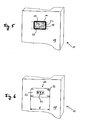
- Fig. 5 the counter unit 14 is shown as being guided through the opening 20 of the housing wall 18 of the housing 10 in a mounting orientation.
- the counter unit 14 is guided laterally along its longitudinal axis perpendicular to the plane of extension of the opening 22 through the opening 22, in particular pushed through.
- the counter unit 14 After the counter unit 14 has been completely passed through the opening 20, the counter unit 14, as in Fig. 6 shown screwed in their operational orientation with screws 32 to the housing wall. At this time, the inner side of the support plate 22 hides the opening 20, and the seal 26 is engaged with the inner side of the support plate 22, so that the seal 26 effectively seals the interior of the housing 10.
- the counter unit 14 has a length I, which is defined by the distance between the two short sides of the rectangular shape of the support plate 22. How out Fig. 7 can be seen, the counter unit 14 has a maximum width a, which is defined by the distance between the two long sides of the rectangular shape of the support plate 22.
- a maximum height b of the counter unit 14 is defined by the entire extent of the counter unit 14 in the vertical direction, that is to say including the connection connector 24, the carrier plate 22 and the line 16.
- a width c of the opening 20 describes a width of the rectangular opening in the horizontal direction, or in other words the distance of the short sides of the rectangular shape of the opening 20. The distance of the long sides of the rectangular shape of the opening 20 defines a height d of the opening 20th
- the maximum width a of the counter unit 14 is smaller than the width c of the opening 20 and the maximum height b of the counter unit 14 is smaller than the height d of the opening 20. However, the maximum width a of the counter unit 14 is greater than the height d of the opening 20 and Length I of the counter unit 14 is greater than the width c of the opening 20. As in Fig. 6 therefore, the counter unit 14 completely covers the opening 20.
- the counter unit 14 is passed through the opening 20 such that the support plate 22 is aligned with its extension plane substantially parallel to the long sides of the rectangular shape of the opening 20.
- the counter unit 14 and the opening 20 can be passed through the opening 20 in a direction other than the parallel mounting orientation.
- the counter unit 14 can thus be passed, for example, diagonally and / or obliquely through a rectangular shape of the opening 20.
Landscapes
- Engineering & Computer Science (AREA)
- Mechanical Engineering (AREA)
- General Engineering & Computer Science (AREA)
- Compressors, Vaccum Pumps And Other Relevant Systems (AREA)
- Applications Or Details Of Rotary Compressors (AREA)
Abstract
Description
- Die vorliegende Erfindung betrifft eine Vakuumpumpe und ein Verfahren zur Herstellung einer Vakuumpumpe.
- Eine beispielhafte Vakuumpumpe umfasst einen Motor, der innen in einem Gehäuse der Vakuumpumpe angeordnet ist, und eine Steuereinheit für den Motor, die außen an dem Gehäuse angeordnet ist. Dabei muss das Gehäuse zur Bewahrung eines Vakuums in dem Gehäuse gegenüber einem äußeren Bereich abgedichtet werden, während gleichzeitig eine elektrische Verbindung zwischen dem Motor und der Steuereinheit notwendig ist.
- Im Stand der Technik wird bei einem beispielhaften Verfahren zur Herstellung einer solchen Vakuumpumpe der Motor zunächst im Gehäuse angeordnet. Anschließend wird eine Leitung von dem Motor durch eine Öffnung des Gehäuses herausgeführt und die Leitung wird mit einer Anschlusseinheit für die Steuereinheit außerhalb des Gehäuses elektrisch verbunden, z.B. verlötet. Die Anschlusseinheit wird dann von außen an dem Gehäuse befestigt.
- Ein Nachteil an diesem Verfahren besteht darin, dass der Motor erst nach der Verbindung mit der Anschlusseinheit abschließend getestet werden kann. Der Motor kann also erst getestet werden, nachdem er in dem Gehäuse der Vakuumpumpe verbaut ist.
- Es ist eine Aufgabe der Erfindung, die Montage einer Vakuumpumpe zu vereinfachen.
- Die Aufgabe wird durch eine Vakuumpumpe mit den Merkmalen des Anspruchs 1 gelöst, und insbesondere dadurch, dass die Öffnung und die Gegeneinheit hinsichtlich ihrer Abmessungen derart aufeinander abgestimmt sind, dass die Gegeneinheit in einer von der Betriebsorientierung verschiedenen Montageorientierung durch die Öffnung hindurchführbar ist.
- Ein Vorteil der Erfindung besteht darin, dass die Funktionseinheit und die Gegeneinheit bereits vor der Montage der Funktionseinheit in dem Gehäuse der Vakuumpumpe elektrisch und/oder informationstechnisch verbunden werden können. Die Funktionseinheit und die Gegeneinheit können somit erstens unabhängig von den restlichen Komponenten viel früher im Herstellungsprozess der Vakuumpumpe getestet werden. Dadurch lassen sich mögliche Fehler unter geringerem Aufwand beheben. Zweitens wird die Montage selbst vereinfacht und beschleunigt, weil z.B. ein thermisches Fügen von der Leitung an die Gegeneinheit während des Montagevorgangs entfallen kann.
- Insbesondere kann die Verbindung der Leitung an die Gegeneinheit bereits bei der Herstellung in geeigneter Weise gekapselt oder vergossen ausgeführt werden, da die Verbindung später bei der Montage der Vakuumpumpe nicht mehr gelöst zu werden braucht. Dies hat unter anderem den Vorteil, dass die Verbindung sicher und zuverlässig vor äußeren Einflüssen geschützt werden kann und somit dauerhaft geschützt ist.
- Die Funktionseinheit und die Gegeneinheit können also als fertige Komponente der Vakuumpumpe gemeinsam bereitgestellt werden, was die Möglichkeit eröffnet, diese Komponente als Ganzes von einem spezialisierten Hersteller zu beziehen, der selbst einen abschließenden Test der Funktionseinheit vornehmen kann. Außerdem wird durch die Erfindung die Demontage und Reparatur der Vakuumpumpe vereinfacht, da eine gegebenenfalls vorhandene Dichtung z.B. in Form eines O-Rings oder einer Flächendichtung einfach ausgetaucht werden kann, ohne die Gegeneinheit von der Leitung zu trennen.
- Diese Vorteile werden erfindungsgemäß insbesondere auch dann erreicht, wenn die Leitung mit der Gegeneinheit nicht über einen Steckverbinder verbunden ist. In diesem Fall können entsprechende Bauteile eingespart werden, während die Montage noch weiter vereinfacht wird.
- Die Funktionseinheit kann einen Motor für die Vakuumpumpe umfassen. Alternativ oder zusätzlich kann die Funktionseinheit weitere Einrichtungen einer Vakuumpumpe umfassen, wie z.B. Mess- und Überwachungseinrichtungen, Ventile oder andere Aktoren zur Steuerung eines Volumenstromes in der Vakuumpumpe.
- Eine elektrische und/oder informationstechnische Verbindung kann Mittel zur Übertragung von Leistung und/oder Informationen umfassen, wobei die Mittel z.B. elektrische Leiter und/oder Lichtwellenleiter umfassen können.
- Die Öffnung muss von einer Kreisform abweichen. Bei einer Ausführungsform weist die Öffnung zumindest im Wesentlichen eine Rechteckform auf. Der Begriff Form bezieht sich auf eine Grundform, die bei weiteren Ausführungsbeispielen der Erfindung z.B. durch Rundungen oder Fasen oder zusätzliche Ausnehmungen von einer idealen Form, wie einer Rechteckform, abweichen kann.
- Bei einer weiteren Ausführungsform der Erfindung weist die Gegeneinheit in der Montageorientierung eine Maximalbreite, eine Maximalhöhe und eine senkrecht zur Ebene der Öffnung verlaufende Länge auf. Dabei ist die Maximalbreite der Gegeneinheit kleiner als eine Breite der Öffnung und die Maximalhöhe der Gegeneinheit ist kleiner als eine Höhe der Öffnung. Die Maximalbreite der Gegeneinheit ist hierbei größer als eine Höhe der Öffnung, und die Länge der Gegeneinheit ist größer als eine Breite der Öffnung.
- Auch bei dieser auf einer relativ einfachen Geometrie basierenden Ausführungsform kann eine vollständige Abdeckung der Öffnung durch die Gegeneinheit gewährleistet werden. Die Begriffe "Höhe", "Breite" und "Länge" beziehen sich lediglich auf die Ausdehnungen von Öffnung und Gegeneinheit in unterschiedlichen Richtungen. Insbesondere ist der Begriff "Höhe" dabei nicht auf eine vertikale Ausdehnungsrichtung beschränkt, sondern kann z.B. auch eine Ausdehnung in horizontaler Richtung beschreiben, wobei in einem solchen Fall der Begriff "Breite" eine Ausdehnung in vertikaler Richtung beschreiben kann. "Höhe", "Breite" und "Länge" können sich aber auch auf beliebige andere, z.B. schräge, Ausdehnungsrichtungen beziehen.
- In der Montageorientierung können die Maximalbreite und die Länge der Gegeneinheit von einem plattenförmigen Element definiert sein. Mit anderen Worten kann die Gegeneinheit ein plattenförmiges Element umfassen, welches in Breite und Länge größer ist als weitere Komponenten der Gegeneinheit, sofern derartige weitere Komponenten vorhanden sind. Die Maximalhöhe wird in diesem Fall von einer Dicke des plattenförmigen Elements zusammen mit einer Ausdehnung der weiteren Komponenten in der Ausdehnungsrichtung der Dicke definiert.
- Bei einer Ausführungsform ist das plattenförmige Element zumindest im Wesentlichen rechteckig. Die Herstellung der Gegeneinheit wird dadurch vereinfacht.
- Das plattenförmige Element kann eine Trägerplatte sein, die eine oder mehrere weitere Komponenten der Gegeneinheit trägt. Die weiteren Komponenten können z.B. relativ einfache Bauteile, wie beispielsweise ein oder mehrere Anschlusselemente, oder auch komplexere Einrichtungen, wie z.B. eine Steuereinheit für die Funktionseinheit, umfassen. Die Komponenten können an der Trägerplatte jeweils dauerhaft oder lösbar befestigt sein.
- Bei einer weiteren Ausführungsform ist die Trägerplatte als Leiterplatte oder Platine ausgebildet ist, die mit der Leitung verbunden ist. Die Leiterplatte oder Platine kann dabei für weitere Leitungsfunktionen ausgebildet sein und/oder weitere Komponenten, wie z.B. Rechen- oder Steuereinheiten, umfassen und/oder elektrisch verbinden.
- Die Gegeneinheit kann zumindest einen mit der Leitung verbundenen Anschlussverbinder umfassen, an den eine mit der Funktionseinheit zu verbindende weitere Funktionseinheit anschließbar ist. Dadurch lässt sich die Gegeneinheit relativ klein ausführen, weil zusätzlich notwendige Komponenten gewissermaßen in die weitere Funktionseinheit "ausgelagert" werden können. Somit ist nur eine kleine Öffnung in der Gehäusewand nötig, durch welche nur eine relativ kleine Gegeneinheit hindurchgeführt werden muss. Der häufig knappe Bauraum in einer Vakuumpumpe kann somit besser ausgenutzt werden. Die weitere Funktionseinheit kann z.B. eine Steuereinheit und/oder ein Netzteil für die Funktionseinheit, z.B. für einen Motor, in dem Gehäuse umfassen.
- Der Anschlussverbinder kann z.B. als Stecker oder als Buchse für eine Buchse bzw. einen Stecker der weiteren Funktionseinheit ausgebildet sein. Der Anschlussverbinder kann an einer in der Betriebsorientierung äußeren Seite der Gegeneinheit angeordnet und mit der Leitung auf der inneren Seite der Gegeneinheit verbunden sein. Ein Anschlussverbinder lässt sich insbesondere mit einer Leiterplatte der Gegeneinheit kombinieren, wobei der Anschlussverbinder zumindest einen Pin aufweisen kann, der durch die Leiterplatte hindurchgeführt wird und auf der inneren Seite der Leiterplatte mit der Leitung verlötet wird. Alternativ oder zusätzlich kann der Anschlussverbinder auf der außen befindlichen Oberfläche der Leiterplatte angebracht sein und durch Leiterbahnen mit der inneren Seite der Leiterplatte verbunden und dort mit der Leitung verbunden sein.
- Bei einer anderen Ausführungsform ist die Gegeneinheit an die Gehäusewand geschraubt. Somit wird eine einfache, lösbare Verbindung der Gegeneinheit mit der Gehäusewand gewährleistet.
- Zwischen der Gegeneinheit und der Gehäusewand kann eine Dichtung vorgesehen sein.
- Bei einer Ausführungsform weist die Gehäusewand und/oder die Gegeneinheit eine Vertiefung zur Aufnahme der Dichtung auf. In dieser Vertiefung lässt sich die Dichtung, beispielsweise ein O-Ring, sicher festlegen und z.B. durch Anschrauben der Gegeneinheit an die Gehäusewand definiert komprimieren, um die erforderliche Dichtwirkung zu erzielen.
- Die Leitung kann flexibel sein. Die Gegeneinheit lässt sich dadurch besonders einfach durch die Öffnung hindurchführen. Insbesondere umfasst die Leitung ein oder mehrere Kabel, die jeweils eine oder mehrere Adern aufweisen können.
- In einer Weiterbildung ist die Leitung mit der Gegeneinheit unlösbar verbunden. Die Leitung kann mit der Gegeneinheit beispielsweise verlötet und/oder vergossen sein. Dadurch werden die Stabilität der Verbindung und der Schutz vor äußeren Einflüssen verbessert.
- Die Aufgabe wird ferner durch ein Verfahren zur Herstellung einer Vakuumpumpe nach Anspruch 15 gelöst, welches z.B. entsprechend den vorstehend genannten Ausführungsformen der Vorrichtung weiter verbessert werden kann.
- Weitere Ausführungsformen sind in den abhängigen Ansprüchen, der Beschreibung und den Figuren angegeben.
- Die Erfindung wird nachfolgend lediglich beispielhaft unter Bezugnahme auf die schematische Zeichnung erläutert.
- Fig. 1
- zeigt eine Gegeneinheit und eine mit dieser verbundene Funktionseinheit gemäß der Erfindung.
- Fig. 2
- zeigt die Gegeneinheit in einer Seitenansicht.
- Fig. 3
- zeigt die Gegeneinheit in einer Rückansicht.
- Fig. 4
- zeigt einen Abschnitt eines erfindungsgemäßen Gehäuses mit einer Öffnung in einer Gehäusewand.
- Fig. 5
- zeigt die Gegeneinheit, die in einer Montageorientierung durch die Öffnung hindurchgeführt wird.
- Fig. 6
- zeigt die Gegeneinheit, die in einer Betriebsorientierung an der Gehäusewand befestigt ist.
- In
Fig. 1 sind eine Funktionseinheit 12 und eine Gegeneinheit 14 dargestellt, die über drei Leitungen 16 verbunden sind. Die Funktionseinheit 12 kann zum Beispiel einen Motor der Vakuumpumpe umfassen. Die Gegeneinheit 14 umfasst eine als Leiterplatte ausgeführte Trägerplatte 22, die einen Anschlussverbinder 24 trägt. Der Anschlussverbinder 24 ist als Buchse für einen Stecker einer weiteren Funktionseinheit, wie zum Beispiel einem Steuergerät für den Motor der Vakuumpumpe, ausgeführt. Die drei Leitungen 16 sind jeweils mit einem Kontaktpunkt der Buchse des Anschlussverbinders 24 verbunden und z.B. je einer Phase eines elektrischen Antriebs des Motors zugeordnet. - Die Trägerplatte 22 weist eine Rechteckform auf, deren vier Ecken zur besseren Handhabung der Gegeneinheit 14 abgerundet sind. In der Nähe der Ecken weist die Trägerplatte 22 vier Durchgangsbohrungen 28 auf, durch welche jeweils eine Schraube zur Befestigung der Gegeneinheit hindurchgeführt werden kann.
- In
Fig. 1 ist die Gegeneinheit 14 mit ihrer bezogen auf eine Betriebsorientierung äußeren Seite gezeigt. Der Begriff "Betriebsorientierung" beschreibt eine Anordnung der Gegeneinheit in einem Zustand, in dem sie, wie inFig. 6 gezeigt, an einer Gehäusewand 18 eines Gehäuses 10 befestigt ist. Mit anderen Worten bezieht sich der Begriff "Betriebsorientierung" auf die Orientierung der Gegeneinheit 14 relativ zu dem Gehäuse 10 während des Betriebs der Vakuumpumpe. Die inFig. 1 nicht gezeigte innere Seite der Trägerplatte 22 ist somit in der Betriebsorientierung dem Inneren des Gehäuses 10 zugewandt, während die dargestellte äußere Seite der Trägerplatte 22 von dem Gehäuse 10 abgewandt ist, wie es inFig. 6 gezeigt ist. -
Fig. 2 zeigt die Gegeneinheit 14 in einer Seitenansicht. Der Anschlussverbinder 24 ist auf der äußeren - hier oberen - Seite der Trägerplatte 22 befestigt. An der inneren - hier unteren - Seite der Trägerplatte 22 entspringen die Leitungen 16, die zu der hier nicht dargestellten Funktionseinheit 12 führen. Der Anschlussverbinder 24 ist durch die Trägerplatte 22 hindurch mit den Leitungen 16 elektrisch verbunden. - In
Fig. 3 ist die innere Seite der Trägerplatte 22 der Gegeneinheit 14 dargestellt. Die Leitungen 16 sind jeweils mit der Trägerplatte 22 und mit Pins der Buchse des hier verdeckten Anschlussverbinders 24 verlötet, so dass die Leitungen 16 und der Anschlussverbinder 24 elektrisch miteinander verbunden sind und an der Trägerplatte 22 dauerhaft befestigt sind. -
Fig. 4 zeigt einen Abschnitt eines Gehäuses 10 einer Vakuumpumpe. Das Gehäuse 10 umfasst eine Gehäusewand 18, in welcher eine rechteckige Öffnung 20 ausgebildet ist. Die Öffnung wird von einer Dichtung 26 umrahmt. Passend zu den Durchgangsbohrungen 28 der Trägerplatte 22 weist die Gehäusewand 18 vier Gewindebohrungen 30 auf, in denen Schrauben zur Befestigung der Gegeneinheit 14 an der Gehäusewand 18 eingeschraubt werden können. - In
Fig. 5 ist die Gegeneinheit 14 gezeigt, wie sie in einer Montageorientierung durch die Öffnung 20 der Gehäusewand 18 des Gehäuses 10 hindurchgeführt wird. Die Gegeneinheit 14 wird dabei seitlich entlang ihrer Längsachse senkrecht zur Erstreckungsebene der Öffnung 22 durch die Öffnung 22 hindurchgeführt, insbesondere hindurchgeschoben. - Nachdem die Gegeneinheit 14 vollständig durch die Öffnung 20 hindurchgeführt wurde, wird die Gegeneinheit 14, wie in
Fig. 6 dargestellt, in ihrer Betriebsorientierung mit Schrauben 32 an die Gehäusewand geschraubt. Dabei verdeckt die innere Seite der Trägerplatte 22 die Öffnung 20 und die Dichtung 26 wird mit der inneren Seite der Trägerplatte 22 in Eingriff gebracht, so dass die Dichtung 26 das Innere des Gehäuses 10 wirksam abdichtet. - In den
Fig. 6 und7 sind Größenverhältnisse von Gegeneinheit 14 und Öffnung 20 dargestellt, die es ermöglichen, dass die Gegeneinheit 14 in der Montageorientierung durch die Öffnung 20 hindurchführbar ist, die Öffnung 20 aber in der Betriebsorientierung abdeckt. Dazu ist inFig. 7 die Öffnung 20 derFig. 5 vergrößert dargestellt. - Die Gegeneinheit 14 weist eine Länge I auf, die durch den Abstand der zwei kurzen Seiten der Rechteckform der Trägerplatte 22 definiert ist. Wie aus
Fig. 7 ersichtlich, weist die Gegeneinheit 14 eine Maximalbreite a auf, die durch den Abstand der beiden langen Seiten der Rechteckform der Trägerplatte 22 definiert ist. - Eine Maximalhöhe b der Gegeneinheit 14 ist durch die gesamte Ausdehnung der Gegeneinheit 14 in vertikaler Richtung, das heißt einschließlich des Anschlussverbinders 24, der Trägerplatte 22 und der Leitung 16, definiert. Eine Breite c der Öffnung 20 beschreibt eine Breite der rechteckigen Öffnung in horizontaler Richtung oder mit anderen Worten den Abstand der kurzen Seiten der Rechteckform der Öffnung 20. Der Abstand der langen Seiten der Rechteckform der Öffnung 20 definiert eine Höhe d der Öffnung 20.
- Die Maximalbreite a der Gegeneinheit 14 ist kleiner als die Breite c der Öffnung 20 und die Maximalhöhe b der Gegeneinheit 14 ist kleiner als die Höhe d der Öffnung 20. Die Maximalbreite a der Gegeneinheit 14 ist aber größer als die Höhe d der Öffnung 20 und die Länge I der Gegeneinheit 14 ist größer als die Breite c der Öffnung 20. Wie in
Fig. 6 dargestellt deckt daher die Gegeneinheit 14 die Öffnung 20 vollständig ab. - In der gezeigten Ausführungsform wird die Gegeneinheit 14 derart durch die Öffnung 20 hindurchgeführt, dass die Trägerplatte 22 mit ihrer Erstreckungsebene im Wesentlichen parallel zu den langen Seiten der Rechteckform der Öffnung 20 ausgerichtet ist. Es sind nicht nur andere Formen für die Gegeneinheit 14 und die Öffnung 20, wie zum Beispiel elliptische, parallelogrammartige oder unregelmäßige Formen, denkbar. Auch kann die Gegeneinheit 14 in einer anderen als der parallelen Montageorientierung durch die Öffnung 20 hindurchgeführt werden. Die Gegeneinheit 14 kann also zum Beispiel diagonal und/oder schräg durch eine Rechteckform der Öffnung 20 hindurchgeführt werden.
-
- 10
- Gehäuse
- 12
- Funktionseinheit
- 14
- Gegeneinheit
- 16
- Leitung
- 18
- Gehäusewand
- 20
- Öffnung
- 22
- Trägerplatte
- 24
- Anschlussverbinder
- 26
- Dichtung
- 28
- Durchgangsbohrung
- 30
- Gewindebohrung
- 32
- Schraube
- a
- Maximalbreite der Gegeneinheit
- b
- Maximalhöhe der Gegeneinheit
- c
- Breite der Öffnung
- d
- Höhe der Öffnung
- l
- Länge der Gegeneinheit
Claims (15)
- Vakuumpumpe mit
einem Gehäuse (10),
zumindest einer im Gehäuse (10) angeordneten Funktionseinheit (12), und wenigstens einer außerhalb des Gehäuses (10) angeordneten Gegeneinheit (14), die über wenigstens eine Leitung (16) mit der Funktionseinheit (12) elektrisch und/oder informationstechnisch verbunden ist,
wobei die Leitung (16) durch eine in einer Gehäusewand (18) ausgebildete Öffnung (20) hindurch verläuft,
wobei die Gegeneinheit (14) in einer Betriebsorientierung außen an der Gehäusewand (18) angebracht ist und die Öffnung (20) abdeckt, und wobei die Öffnung (20) und die Gegeneinheit (14) hinsichtlich ihrer Abmessungen derart aufeinander abgestimmt sind, dass die Gegeneinheit (14) in einer von der Betriebsorientierung verschiedenen Montageorientierung durch die Öffnung (20) hindurchführbar ist. - Vorrichtung nach Anspruch 1,
dadurch gekennzeichnet, dass
die Öffnung (20) von einer Kreisform abweicht. - Vorrichtung nach Anspruch 1 oder 2,
dadurch gekennzeichnet, dass
die Öffnung (20) zumindest im Wesentlichen eine Rechteckform oder Quadratform aufweist. - Vorrichtung nach zumindest einem der vorstehenden Ansprüche,
dadurch gekennzeichnet, dass die Gegeneinheit (14) in der Montageorientierung eine Maximalbreite (a), eine Maximalhöhe (b) und eine senkrecht zur Ebene der Öffnung (20) verlaufende Länge (l) aufweist,
wobei die Maximalbreite (a) der Gegeneinheit (14) kleiner ist als eine Breite (c) der Öffnung (20) und die Maximalhöhe (b) der Gegeneinheit (14) kleiner ist als eine Höhe (d) der Öffnung (20),
wobei die Maximalbreite (a) der Gegeneinheit (14) größer ist als eine Höhe (d) der Öffnung (14), und
wobei die Länge (I) der Gegeneinheit (14) größer ist als eine Breite (c) der Öffnung (20). - Vorrichtung nach zumindest einem der vorstehenden Ansprüche,
dadurch gekennzeichnet, dass in der Montageorientierung die Maximalbreite (a) und die Länge (I) der Gegeneinheit (14) von einem plattenförmigen Element (22) definiert sind. - Vorrichtung nach Anspruch 5,
dadurch gekennzeichnet, dass das plattenförmige Element (22) zumindest im Wesentlichen rechteckig oder quadratisch ist. - Vorrichtung nach Anspruch 5 oder 6,
dadurch gekennzeichnet, dass das plattenförmige Element eine Trägerplatte (22) ist, die eine oder mehrere weitere Komponenten der Gegeneinheit (14) trägt. - Vorrichtung nach Anspruch 7,
dadurch gekennzeichnet, dass die Trägerplatte (22) als Leiterplatte oder Platine ausgebildet ist, die mit der Leitung (16) verbunden ist. - Vorrichtung nach zumindest einem der vorstehenden Ansprüche,
dadurch gekennzeichnet, dass die Gegeneinheit (14) zumindest einen mit der Leitung verbundenen Anschlussverbinder (24) umfasst, an den eine mit der Funktionseinheit (12) zu verbindende weitere Funktionseinheit anschließbar ist. - Vorrichtung nach zumindest einem der vorstehenden Ansprüche,
dadurch gekennzeichnet, dass die Gegeneinheit (14) an die Gehäusewand (18) geschraubt ist. - Vorrichtung nach zumindest einem der vorstehenden Ansprüche,
dadurch gekennzeichnet, dass zwischen der Gegeneinheit (14) und der Gehäusewand (18) eine Dichtung (26) vorgesehen ist. - Vorrichtung nach Anspruch 11,
dadurch gekennzeichnet, dass die Gehäusewand (18) und/oder die Gegeneinheit (14) eine Vertiefung zur Aufnahme der Dichtung (18) aufweisen. - Vorrichtung nach zumindest einem der vorstehenden Ansprüche,
dadurch gekennzeichnet, dass die Leitung (16) flexibel ist. - Vorrichtung nach zumindest einem der vorstehenden Ansprüche,
dadurch gekennzeichnet, dass
die Leitung (16) mit der Gegeneinheit (14) unlösbar verbunden ist. - Verfahren zur Herstellung einer Vakuumpumpe, die ein Gehäuse (10) und zumindest eine innerhalb des Gehäuses (10) anzuordnende Funktionseinheit (12) umfasst, zu der im Betrieb der Vakuumpumpe von außerhalb des Gehäuses (10) eine elektrische und/oder informationstechnische Verbindung besteht, wobei das Verfahren die Schritte umfasst,
dass vor dem Anordnen der Funktionseinheit (12) im Gehäuse (10) die Funktionseinheit (12) über wenigstens eine Leitung (16) mit einer Gegeneinheit (14) elektrisch und/oder informationstechnisch verbunden wird, dass die Funktionseinheit (12) im Gehäuse (10) angeordnet und die Gegeneinheit (14) von innerhalb des Gehäuses (10) durch eine in einer Gehäusewand (18) ausgebildete Öffnung (20) hindurch nach außen geführt wird, und
dass die Gegeneinheit (14) außen an der Gehäusewand (18) in einer Betriebsorientierung angebracht wird, in der die Gegeneinheit (14) die Öffnung (20) abdeckt,
wobei die Öffnung (20) und die Gegeneinheit (14) hinsichtlich ihrer Abmessungen derart aufeinander abgestimmt werden, dass die Gegeneinheit (14) in einer von der Betriebsorientierung verschiedenen Montageorientierung durch die Öffnung (20) hindurchgeführt werden kann.
Priority Applications (2)
| Application Number | Priority Date | Filing Date | Title |
|---|---|---|---|
| EP15165989.3A EP3088737B1 (de) | 2015-04-30 | 2015-04-30 | Vakuumpumpe und verfahren zur herstellung einer vakuumpumpe |
| JP2016016812A JP6148743B2 (ja) | 2015-04-30 | 2016-02-01 | 真空ポンプ及び真空ポンプの製造の為の方法 |
Applications Claiming Priority (1)
| Application Number | Priority Date | Filing Date | Title |
|---|---|---|---|
| EP15165989.3A EP3088737B1 (de) | 2015-04-30 | 2015-04-30 | Vakuumpumpe und verfahren zur herstellung einer vakuumpumpe |
Publications (2)
| Publication Number | Publication Date |
|---|---|
| EP3088737A1 true EP3088737A1 (de) | 2016-11-02 |
| EP3088737B1 EP3088737B1 (de) | 2020-06-17 |
Family
ID=53039322
Family Applications (1)
| Application Number | Title | Priority Date | Filing Date |
|---|---|---|---|
| EP15165989.3A Active EP3088737B1 (de) | 2015-04-30 | 2015-04-30 | Vakuumpumpe und verfahren zur herstellung einer vakuumpumpe |
Country Status (2)
| Country | Link |
|---|---|
| EP (1) | EP3088737B1 (de) |
| JP (1) | JP6148743B2 (de) |
Cited By (3)
| Publication number | Priority date | Publication date | Assignee | Title |
|---|---|---|---|---|
| EP3564534A4 (de) * | 2016-12-28 | 2020-08-12 | Edwards Japan Limited | Vakuumpumpe und verbinder und bei der vakuumpumpe angewandte steuerungsvorrichtung |
| EP4424994A1 (de) * | 2023-03-01 | 2024-09-04 | RAPA Automotive GmbH & Co. KG | Flexibles motor-pumpe-system |
| US12710037B2 (en) * | 2023-03-01 | 2026-08-18 | Rapa Automotive Gmbh & Co. Kg | Flexible motor pump system |
Citations (3)
| Publication number | Priority date | Publication date | Assignee | Title |
|---|---|---|---|---|
| US2073547A (en) * | 1935-08-06 | 1937-03-09 | Paul F Berry | Pump |
| US20020094277A1 (en) * | 1993-07-16 | 2002-07-18 | Helix Technology Corporation | Electronically controlled vacuum pump |
| EP1843043A2 (de) * | 2006-04-07 | 2007-10-10 | Pfeiffer Vacuum Gmbh | Vakuumpumpe mit Antriebsgerät |
Family Cites Families (4)
| Publication number | Priority date | Publication date | Assignee | Title |
|---|---|---|---|---|
| JPS6393752U (de) * | 1986-12-08 | 1988-06-17 | ||
| JPH05284687A (ja) * | 1992-03-31 | 1993-10-29 | Matsushita Seiko Co Ltd | 電動機の接続装置 |
| JP3172822U (ja) * | 2011-10-24 | 2012-01-12 | 株式会社島津製作所 | 真空ポンプ |
| JP5991077B2 (ja) * | 2012-08-27 | 2016-09-14 | ダイキン工業株式会社 | 接続端子の取付構造、ターボ圧縮機及びターボ冷凍機 |
-
2015
- 2015-04-30 EP EP15165989.3A patent/EP3088737B1/de active Active
-
2016
- 2016-02-01 JP JP2016016812A patent/JP6148743B2/ja active Active
Patent Citations (3)
| Publication number | Priority date | Publication date | Assignee | Title |
|---|---|---|---|---|
| US2073547A (en) * | 1935-08-06 | 1937-03-09 | Paul F Berry | Pump |
| US20020094277A1 (en) * | 1993-07-16 | 2002-07-18 | Helix Technology Corporation | Electronically controlled vacuum pump |
| EP1843043A2 (de) * | 2006-04-07 | 2007-10-10 | Pfeiffer Vacuum Gmbh | Vakuumpumpe mit Antriebsgerät |
Cited By (4)
| Publication number | Priority date | Publication date | Assignee | Title |
|---|---|---|---|---|
| EP3564534A4 (de) * | 2016-12-28 | 2020-08-12 | Edwards Japan Limited | Vakuumpumpe und verbinder und bei der vakuumpumpe angewandte steuerungsvorrichtung |
| US11081845B2 (en) | 2016-12-28 | 2021-08-03 | Edwards Japan Limited | Vacuum pump, and connector and control device applied to vacuum pump |
| EP4424994A1 (de) * | 2023-03-01 | 2024-09-04 | RAPA Automotive GmbH & Co. KG | Flexibles motor-pumpe-system |
| US12710037B2 (en) * | 2023-03-01 | 2026-08-18 | Rapa Automotive Gmbh & Co. Kg | Flexible motor pump system |
Also Published As
| Publication number | Publication date |
|---|---|
| JP6148743B2 (ja) | 2017-06-14 |
| EP3088737B1 (de) | 2020-06-17 |
| JP2016211537A (ja) | 2016-12-15 |
Similar Documents
| Publication | Publication Date | Title |
|---|---|---|
| DE102012204145A1 (de) | Gehäuseblende zur Aufnahme von Steckermodulen | |
| DE102014109351B3 (de) | Steckverbinder mit Schutzleiterbrücke | |
| EP3121485B1 (de) | Kompakter elektrischer linearantrieb für eine zahnstange, insbesondere eines hydraulikventils, und verfahren zu seiner montage | |
| EP3069026B1 (de) | Antriebs- und steuereinrichtung für eine vakuumpumpe, vakuumpumpe sowie verfahren zum herstellen einer steuerplatine für eine vakuumpumpe | |
| EP3345254A1 (de) | Halterahmen | |
| DE102013212834A1 (de) | Elektrisches Stecksystem | |
| EP3000156B1 (de) | Kontaktvorrichtung zum herstellen eines elektrischen kontaktes zwischen einer leiterplatine und einem elektromotor | |
| EP2992594A2 (de) | Gehäuseanordnung mit einem gehäusebauteil für eine elektrische maschine und einer elektrischen leiterplatte | |
| DE102012016155B4 (de) | Türspiegel | |
| DE102016217252A1 (de) | Verfahren und Vorrichtungen zur Bereitstellung eines pneumatischen Druckmittels durch eine Druckmittelquelle für mindestens eine Druckmittelkammer insbesondere eines Fahrzeugsitzes eines Kraftfahrzeugs | |
| DE102016203718A1 (de) | Steuergerät | |
| DE102012102842B4 (de) | Befestigung und Abdichtung von Steckanschlussmodulen in einer Gehäusewand | |
| EP3088737B1 (de) | Vakuumpumpe und verfahren zur herstellung einer vakuumpumpe | |
| EP3231043B1 (de) | Wanddurchführung für steckverbinder | |
| DE102017109899A1 (de) | Elektrischer Verbinder | |
| DE10108414B4 (de) | Elektromotorischer Fensterheberantrieb | |
| EP1978378B1 (de) | Optoelektronische Sensoranordnung | |
| DE4428687C1 (de) | Baugruppe eines elektrischen Geräts | |
| AT517608B1 (de) | Elektronikeinheit für ein Durchflussmessgerät | |
| WO2018210373A1 (de) | Halterahmen für einen steckverbinder oder einen anbauflansch zur halterung einer leiterplatte | |
| DE102005021502B4 (de) | Modulares elektrisches Gerät | |
| WO2017021017A1 (de) | Fortbewegungsmittel, batteriesystem, gehäuse für ein batteriesystem, baugruppe für ein batteriesystem, service-deckel und verfahren zur montage eines batteriesystems | |
| EP2840689B1 (de) | Kfz-Aggregat und Verfahren zur Befestigung eines Steckers an einem Kfz-Aggregat | |
| DE102014220114B4 (de) | Durchführungseinheit zur Durchführung elektrischer Energie durch eine Schwenkeinheit und System aus einer Schwenkeinheit und einer Durchführungseinheit | |
| EP2263292A1 (de) | Zugentlastungs-vorrichtung |
Legal Events
| Date | Code | Title | Description |
|---|---|---|---|
| PUAI | Public reference made under article 153(3) epc to a published international application that has entered the european phase |
Free format text: ORIGINAL CODE: 0009012 |
|
| AK | Designated contracting states |
Kind code of ref document: A1 Designated state(s): AL AT BE BG CH CY CZ DE DK EE ES FI FR GB GR HR HU IE IS IT LI LT LU LV MC MK MT NL NO PL PT RO RS SE SI SK SM TR |
|
| AX | Request for extension of the european patent |
Extension state: BA ME |
|
| STAA | Information on the status of an ep patent application or granted ep patent |
Free format text: STATUS: REQUEST FOR EXAMINATION WAS MADE |
|
| 17P | Request for examination filed |
Effective date: 20170327 |
|
| RBV | Designated contracting states (corrected) |
Designated state(s): AL AT BE BG CH CY CZ DE DK EE ES FI FR GB GR HR HU IE IS IT LI LT LU LV MC MK MT NL NO PL PT RO RS SE SI SK SM TR |
|
| STAA | Information on the status of an ep patent application or granted ep patent |
Free format text: STATUS: EXAMINATION IS IN PROGRESS |
|
| 17Q | First examination report despatched |
Effective date: 20171107 |
|
| REG | Reference to a national code |
Ref country code: DE Ref legal event code: R079 Ref document number: 502015012790 Country of ref document: DE Free format text: PREVIOUS MAIN CLASS: F04B0035040000 Ipc: F04D0029640000 |
|
| GRAP | Despatch of communication of intention to grant a patent |
Free format text: ORIGINAL CODE: EPIDOSNIGR1 |
|
| STAA | Information on the status of an ep patent application or granted ep patent |
Free format text: STATUS: GRANT OF PATENT IS INTENDED |
|
| RIC1 | Information provided on ipc code assigned before grant |
Ipc: F04B 35/04 20060101ALI20200210BHEP Ipc: F04C 25/02 20060101ALI20200210BHEP Ipc: F04B 37/14 20060101ALI20200210BHEP Ipc: F04B 39/12 20060101ALI20200210BHEP Ipc: F04D 19/04 20060101ALI20200210BHEP Ipc: F04C 23/00 20060101ALI20200210BHEP Ipc: F04D 29/64 20060101AFI20200210BHEP Ipc: F04D 25/06 20060101ALI20200210BHEP Ipc: F04B 39/14 20060101ALI20200210BHEP |
|
| INTG | Intention to grant announced |
Effective date: 20200309 |
|
| GRAS | Grant fee paid |
Free format text: ORIGINAL CODE: EPIDOSNIGR3 |
|
| GRAA | (expected) grant |
Free format text: ORIGINAL CODE: 0009210 |
|
| STAA | Information on the status of an ep patent application or granted ep patent |
Free format text: STATUS: THE PATENT HAS BEEN GRANTED |
|
| AK | Designated contracting states |
Kind code of ref document: B1 Designated state(s): AL AT BE BG CH CY CZ DE DK EE ES FI FR GB GR HR HU IE IS IT LI LT LU LV MC MK MT NL NO PL PT RO RS SE SI SK SM TR |
|
| REG | Reference to a national code |
Ref country code: GB Ref legal event code: FG4D Free format text: NOT ENGLISH |
|
| REG | Reference to a national code |
Ref country code: CH Ref legal event code: EP |
|
| REG | Reference to a national code |
Ref country code: IE Ref legal event code: FG4D Free format text: LANGUAGE OF EP DOCUMENT: GERMAN |
|
| REG | Reference to a national code |
Ref country code: DE Ref legal event code: R096 Ref document number: 502015012790 Country of ref document: DE |
|
| REG | Reference to a national code |
Ref country code: AT Ref legal event code: REF Ref document number: 1281642 Country of ref document: AT Kind code of ref document: T Effective date: 20200715 |
|
| PG25 | Lapsed in a contracting state [announced via postgrant information from national office to epo] |
Ref country code: GR Free format text: LAPSE BECAUSE OF FAILURE TO SUBMIT A TRANSLATION OF THE DESCRIPTION OR TO PAY THE FEE WITHIN THE PRESCRIBED TIME-LIMIT Effective date: 20200918 Ref country code: NO Free format text: LAPSE BECAUSE OF FAILURE TO SUBMIT A TRANSLATION OF THE DESCRIPTION OR TO PAY THE FEE WITHIN THE PRESCRIBED TIME-LIMIT Effective date: 20200917 Ref country code: SE Free format text: LAPSE BECAUSE OF FAILURE TO SUBMIT A TRANSLATION OF THE DESCRIPTION OR TO PAY THE FEE WITHIN THE PRESCRIBED TIME-LIMIT Effective date: 20200617 Ref country code: FI Free format text: LAPSE BECAUSE OF FAILURE TO SUBMIT A TRANSLATION OF THE DESCRIPTION OR TO PAY THE FEE WITHIN THE PRESCRIBED TIME-LIMIT Effective date: 20200617 Ref country code: LT Free format text: LAPSE BECAUSE OF FAILURE TO SUBMIT A TRANSLATION OF THE DESCRIPTION OR TO PAY THE FEE WITHIN THE PRESCRIBED TIME-LIMIT Effective date: 20200617 |
|
| REG | Reference to a national code |
Ref country code: LT Ref legal event code: MG4D |
|
| REG | Reference to a national code |
Ref country code: NL Ref legal event code: MP Effective date: 20200617 |
|
| PG25 | Lapsed in a contracting state [announced via postgrant information from national office to epo] |
Ref country code: LV Free format text: LAPSE BECAUSE OF FAILURE TO SUBMIT A TRANSLATION OF THE DESCRIPTION OR TO PAY THE FEE WITHIN THE PRESCRIBED TIME-LIMIT Effective date: 20200617 Ref country code: HR Free format text: LAPSE BECAUSE OF FAILURE TO SUBMIT A TRANSLATION OF THE DESCRIPTION OR TO PAY THE FEE WITHIN THE PRESCRIBED TIME-LIMIT Effective date: 20200617 Ref country code: BG Free format text: LAPSE BECAUSE OF FAILURE TO SUBMIT A TRANSLATION OF THE DESCRIPTION OR TO PAY THE FEE WITHIN THE PRESCRIBED TIME-LIMIT Effective date: 20200917 Ref country code: RS Free format text: LAPSE BECAUSE OF FAILURE TO SUBMIT A TRANSLATION OF THE DESCRIPTION OR TO PAY THE FEE WITHIN THE PRESCRIBED TIME-LIMIT Effective date: 20200617 |
|
| PG25 | Lapsed in a contracting state [announced via postgrant information from national office to epo] |
Ref country code: NL Free format text: LAPSE BECAUSE OF FAILURE TO SUBMIT A TRANSLATION OF THE DESCRIPTION OR TO PAY THE FEE WITHIN THE PRESCRIBED TIME-LIMIT Effective date: 20200617 Ref country code: AL Free format text: LAPSE BECAUSE OF FAILURE TO SUBMIT A TRANSLATION OF THE DESCRIPTION OR TO PAY THE FEE WITHIN THE PRESCRIBED TIME-LIMIT Effective date: 20200617 |
|
| PG25 | Lapsed in a contracting state [announced via postgrant information from national office to epo] |
Ref country code: RO Free format text: LAPSE BECAUSE OF FAILURE TO SUBMIT A TRANSLATION OF THE DESCRIPTION OR TO PAY THE FEE WITHIN THE PRESCRIBED TIME-LIMIT Effective date: 20200617 Ref country code: SM Free format text: LAPSE BECAUSE OF FAILURE TO SUBMIT A TRANSLATION OF THE DESCRIPTION OR TO PAY THE FEE WITHIN THE PRESCRIBED TIME-LIMIT Effective date: 20200617 Ref country code: EE Free format text: LAPSE BECAUSE OF FAILURE TO SUBMIT A TRANSLATION OF THE DESCRIPTION OR TO PAY THE FEE WITHIN THE PRESCRIBED TIME-LIMIT Effective date: 20200617 Ref country code: ES Free format text: LAPSE BECAUSE OF FAILURE TO SUBMIT A TRANSLATION OF THE DESCRIPTION OR TO PAY THE FEE WITHIN THE PRESCRIBED TIME-LIMIT Effective date: 20200617 Ref country code: PT Free format text: LAPSE BECAUSE OF FAILURE TO SUBMIT A TRANSLATION OF THE DESCRIPTION OR TO PAY THE FEE WITHIN THE PRESCRIBED TIME-LIMIT Effective date: 20201019 |
|
| PG25 | Lapsed in a contracting state [announced via postgrant information from national office to epo] |
Ref country code: SK Free format text: LAPSE BECAUSE OF FAILURE TO SUBMIT A TRANSLATION OF THE DESCRIPTION OR TO PAY THE FEE WITHIN THE PRESCRIBED TIME-LIMIT Effective date: 20200617 Ref country code: PL Free format text: LAPSE BECAUSE OF FAILURE TO SUBMIT A TRANSLATION OF THE DESCRIPTION OR TO PAY THE FEE WITHIN THE PRESCRIBED TIME-LIMIT Effective date: 20200617 Ref country code: IS Free format text: LAPSE BECAUSE OF FAILURE TO SUBMIT A TRANSLATION OF THE DESCRIPTION OR TO PAY THE FEE WITHIN THE PRESCRIBED TIME-LIMIT Effective date: 20201017 |
|
| REG | Reference to a national code |
Ref country code: DE Ref legal event code: R097 Ref document number: 502015012790 Country of ref document: DE |
|
| PLBE | No opposition filed within time limit |
Free format text: ORIGINAL CODE: 0009261 |
|
| STAA | Information on the status of an ep patent application or granted ep patent |
Free format text: STATUS: NO OPPOSITION FILED WITHIN TIME LIMIT |
|
| PG25 | Lapsed in a contracting state [announced via postgrant information from national office to epo] |
Ref country code: DK Free format text: LAPSE BECAUSE OF FAILURE TO SUBMIT A TRANSLATION OF THE DESCRIPTION OR TO PAY THE FEE WITHIN THE PRESCRIBED TIME-LIMIT Effective date: 20200617 |
|
| 26N | No opposition filed |
Effective date: 20210318 |
|
| PG25 | Lapsed in a contracting state [announced via postgrant information from national office to epo] |
Ref country code: SI Free format text: LAPSE BECAUSE OF FAILURE TO SUBMIT A TRANSLATION OF THE DESCRIPTION OR TO PAY THE FEE WITHIN THE PRESCRIBED TIME-LIMIT Effective date: 20200617 |
|
| PG25 | Lapsed in a contracting state [announced via postgrant information from national office to epo] |
Ref country code: MC Free format text: LAPSE BECAUSE OF FAILURE TO SUBMIT A TRANSLATION OF THE DESCRIPTION OR TO PAY THE FEE WITHIN THE PRESCRIBED TIME-LIMIT Effective date: 20200617 |
|
| PG25 | Lapsed in a contracting state [announced via postgrant information from national office to epo] |
Ref country code: LU Free format text: LAPSE BECAUSE OF NON-PAYMENT OF DUE FEES Effective date: 20210430 |
|
| REG | Reference to a national code |
Ref country code: BE Ref legal event code: MM Effective date: 20210430 |
|
| PG25 | Lapsed in a contracting state [announced via postgrant information from national office to epo] |
Ref country code: LI Free format text: LAPSE BECAUSE OF NON-PAYMENT OF DUE FEES Effective date: 20210430 Ref country code: CH Free format text: LAPSE BECAUSE OF NON-PAYMENT OF DUE FEES Effective date: 20210430 Ref country code: FR Free format text: LAPSE BECAUSE OF NON-PAYMENT OF DUE FEES Effective date: 20210430 |
|
| PG25 | Lapsed in a contracting state [announced via postgrant information from national office to epo] |
Ref country code: IE Free format text: LAPSE BECAUSE OF NON-PAYMENT OF DUE FEES Effective date: 20210430 |
|
| PG25 | Lapsed in a contracting state [announced via postgrant information from national office to epo] |
Ref country code: IS Free format text: LAPSE BECAUSE OF FAILURE TO SUBMIT A TRANSLATION OF THE DESCRIPTION OR TO PAY THE FEE WITHIN THE PRESCRIBED TIME-LIMIT Effective date: 20201017 |
|
| REG | Reference to a national code |
Ref country code: AT Ref legal event code: MM01 Ref document number: 1281642 Country of ref document: AT Kind code of ref document: T Effective date: 20210430 |
|
| PG25 | Lapsed in a contracting state [announced via postgrant information from national office to epo] |
Ref country code: BE Free format text: LAPSE BECAUSE OF NON-PAYMENT OF DUE FEES Effective date: 20210430 |
|
| PG25 | Lapsed in a contracting state [announced via postgrant information from national office to epo] |
Ref country code: AT Free format text: LAPSE BECAUSE OF NON-PAYMENT OF DUE FEES Effective date: 20210430 |
|
| PG25 | Lapsed in a contracting state [announced via postgrant information from national office to epo] |
Ref country code: HU Free format text: LAPSE BECAUSE OF FAILURE TO SUBMIT A TRANSLATION OF THE DESCRIPTION OR TO PAY THE FEE WITHIN THE PRESCRIBED TIME-LIMIT; INVALID AB INITIO Effective date: 20150430 |
|
| PG25 | Lapsed in a contracting state [announced via postgrant information from national office to epo] |
Ref country code: CY Free format text: LAPSE BECAUSE OF FAILURE TO SUBMIT A TRANSLATION OF THE DESCRIPTION OR TO PAY THE FEE WITHIN THE PRESCRIBED TIME-LIMIT Effective date: 20200617 |
|
| PG25 | Lapsed in a contracting state [announced via postgrant information from national office to epo] |
Ref country code: MK Free format text: LAPSE BECAUSE OF FAILURE TO SUBMIT A TRANSLATION OF THE DESCRIPTION OR TO PAY THE FEE WITHIN THE PRESCRIBED TIME-LIMIT Effective date: 20200617 |
|
| PG25 | Lapsed in a contracting state [announced via postgrant information from national office to epo] |
Ref country code: MT Free format text: LAPSE BECAUSE OF FAILURE TO SUBMIT A TRANSLATION OF THE DESCRIPTION OR TO PAY THE FEE WITHIN THE PRESCRIBED TIME-LIMIT Effective date: 20200617 |
|
| PG25 | Lapsed in a contracting state [announced via postgrant information from national office to epo] |
Ref country code: TR Free format text: LAPSE BECAUSE OF FAILURE TO SUBMIT A TRANSLATION OF THE DESCRIPTION OR TO PAY THE FEE WITHIN THE PRESCRIBED TIME-LIMIT Effective date: 20200617 |
|
| PGFP | Annual fee paid to national office [announced via postgrant information from national office to epo] |
Ref country code: GB Payment date: 20260423 Year of fee payment: 12 |
|
| PGFP | Annual fee paid to national office [announced via postgrant information from national office to epo] |
Ref country code: IT Payment date: 20260427 Year of fee payment: 12 |
|
| PGFP | Annual fee paid to national office [announced via postgrant information from national office to epo] |
Ref country code: DE Payment date: 20260626 Year of fee payment: 12 |
|
| PGFP | Annual fee paid to national office [announced via postgrant information from national office to epo] |
Ref country code: CZ Payment date: 20260423 Year of fee payment: 12 |