EP3088694A1 - Harnstofflösungs-pumpeneinheit - Google Patents
Harnstofflösungs-pumpeneinheit Download PDFInfo
- Publication number
- EP3088694A1 EP3088694A1 EP15189982.0A EP15189982A EP3088694A1 EP 3088694 A1 EP3088694 A1 EP 3088694A1 EP 15189982 A EP15189982 A EP 15189982A EP 3088694 A1 EP3088694 A1 EP 3088694A1
- Authority
- EP
- European Patent Office
- Prior art keywords
- urea solution
- bracket
- pump unit
- outlet
- adaptor
- Prior art date
- Legal status (The legal status is an assumption and is not a legal conclusion. Google has not performed a legal analysis and makes no representation as to the accuracy of the status listed.)
- Granted
Links
Images








Classifications
-
- F—MECHANICAL ENGINEERING; LIGHTING; HEATING; WEAPONS; BLASTING
- F01—MACHINES OR ENGINES IN GENERAL; ENGINE PLANTS IN GENERAL; STEAM ENGINES
- F01N—GAS-FLOW SILENCERS OR EXHAUST APPARATUS FOR MACHINES OR ENGINES IN GENERAL; GAS-FLOW SILENCERS OR EXHAUST APPARATUS FOR INTERNAL-COMBUSTION ENGINES
- F01N3/00—Exhaust or silencing apparatus having means for purifying, rendering innocuous, or otherwise treating exhaust
- F01N3/08—Exhaust or silencing apparatus having means for purifying, rendering innocuous, or otherwise treating exhaust for rendering innocuous
- F01N3/10—Exhaust or silencing apparatus having means for purifying, rendering innocuous, or otherwise treating exhaust for rendering innocuous by thermal or catalytic conversion of noxious components of exhaust
- F01N3/18—Exhaust or silencing apparatus having means for purifying, rendering innocuous, or otherwise treating exhaust for rendering innocuous by thermal or catalytic conversion of noxious components of exhaust characterised by methods of operation; Control
- F01N3/20—Exhaust or silencing apparatus having means for purifying, rendering innocuous, or otherwise treating exhaust for rendering innocuous by thermal or catalytic conversion of noxious components of exhaust characterised by methods of operation; Control specially adapted for catalytic conversion
- F01N3/206—Adding periodically or continuously substances to exhaust gases for promoting purification, e.g. catalytic material in liquid form, NOx reducing agents
- F01N3/2066—Selective catalytic reduction [SCR]
-
- F—MECHANICAL ENGINEERING; LIGHTING; HEATING; WEAPONS; BLASTING
- F01—MACHINES OR ENGINES IN GENERAL; ENGINE PLANTS IN GENERAL; STEAM ENGINES
- F01N—GAS-FLOW SILENCERS OR EXHAUST APPARATUS FOR MACHINES OR ENGINES IN GENERAL; GAS-FLOW SILENCERS OR EXHAUST APPARATUS FOR INTERNAL-COMBUSTION ENGINES
- F01N3/00—Exhaust or silencing apparatus having means for purifying, rendering innocuous, or otherwise treating exhaust
- F01N3/08—Exhaust or silencing apparatus having means for purifying, rendering innocuous, or otherwise treating exhaust for rendering innocuous
- F01N3/10—Exhaust or silencing apparatus having means for purifying, rendering innocuous, or otherwise treating exhaust for rendering innocuous by thermal or catalytic conversion of noxious components of exhaust
- F01N3/24—Exhaust or silencing apparatus having means for purifying, rendering innocuous, or otherwise treating exhaust for rendering innocuous by thermal or catalytic conversion of noxious components of exhaust characterised by constructional aspects of converting apparatus
- F01N3/28—Construction of catalytic reactors
- F01N3/2896—Liquid catalyst carrier
-
- F—MECHANICAL ENGINEERING; LIGHTING; HEATING; WEAPONS; BLASTING
- F01—MACHINES OR ENGINES IN GENERAL; ENGINE PLANTS IN GENERAL; STEAM ENGINES
- F01N—GAS-FLOW SILENCERS OR EXHAUST APPARATUS FOR MACHINES OR ENGINES IN GENERAL; GAS-FLOW SILENCERS OR EXHAUST APPARATUS FOR INTERNAL-COMBUSTION ENGINES
- F01N3/00—Exhaust or silencing apparatus having means for purifying, rendering innocuous, or otherwise treating exhaust
- F01N3/08—Exhaust or silencing apparatus having means for purifying, rendering innocuous, or otherwise treating exhaust for rendering innocuous
- F01N3/10—Exhaust or silencing apparatus having means for purifying, rendering innocuous, or otherwise treating exhaust for rendering innocuous by thermal or catalytic conversion of noxious components of exhaust
- F01N3/24—Exhaust or silencing apparatus having means for purifying, rendering innocuous, or otherwise treating exhaust for rendering innocuous by thermal or catalytic conversion of noxious components of exhaust characterised by constructional aspects of converting apparatus
- F01N3/28—Construction of catalytic reactors
-
- F—MECHANICAL ENGINEERING; LIGHTING; HEATING; WEAPONS; BLASTING
- F01—MACHINES OR ENGINES IN GENERAL; ENGINE PLANTS IN GENERAL; STEAM ENGINES
- F01N—GAS-FLOW SILENCERS OR EXHAUST APPARATUS FOR MACHINES OR ENGINES IN GENERAL; GAS-FLOW SILENCERS OR EXHAUST APPARATUS FOR INTERNAL-COMBUSTION ENGINES
- F01N3/00—Exhaust or silencing apparatus having means for purifying, rendering innocuous, or otherwise treating exhaust
- F01N3/08—Exhaust or silencing apparatus having means for purifying, rendering innocuous, or otherwise treating exhaust for rendering innocuous
- F01N3/10—Exhaust or silencing apparatus having means for purifying, rendering innocuous, or otherwise treating exhaust for rendering innocuous by thermal or catalytic conversion of noxious components of exhaust
- F01N3/18—Exhaust or silencing apparatus having means for purifying, rendering innocuous, or otherwise treating exhaust for rendering innocuous by thermal or catalytic conversion of noxious components of exhaust characterised by methods of operation; Control
- F01N3/20—Exhaust or silencing apparatus having means for purifying, rendering innocuous, or otherwise treating exhaust for rendering innocuous by thermal or catalytic conversion of noxious components of exhaust characterised by methods of operation; Control specially adapted for catalytic conversion
- F01N3/2006—Periodically heating or cooling catalytic reactors, e.g. at cold starting or overheating
- F01N3/2013—Periodically heating or cooling catalytic reactors, e.g. at cold starting or overheating using electric or magnetic heating means
-
- F—MECHANICAL ENGINEERING; LIGHTING; HEATING; WEAPONS; BLASTING
- F01—MACHINES OR ENGINES IN GENERAL; ENGINE PLANTS IN GENERAL; STEAM ENGINES
- F01N—GAS-FLOW SILENCERS OR EXHAUST APPARATUS FOR MACHINES OR ENGINES IN GENERAL; GAS-FLOW SILENCERS OR EXHAUST APPARATUS FOR INTERNAL-COMBUSTION ENGINES
- F01N3/00—Exhaust or silencing apparatus having means for purifying, rendering innocuous, or otherwise treating exhaust
- F01N3/08—Exhaust or silencing apparatus having means for purifying, rendering innocuous, or otherwise treating exhaust for rendering innocuous
- F01N3/10—Exhaust or silencing apparatus having means for purifying, rendering innocuous, or otherwise treating exhaust for rendering innocuous by thermal or catalytic conversion of noxious components of exhaust
- F01N3/18—Exhaust or silencing apparatus having means for purifying, rendering innocuous, or otherwise treating exhaust for rendering innocuous by thermal or catalytic conversion of noxious components of exhaust characterised by methods of operation; Control
- F01N3/20—Exhaust or silencing apparatus having means for purifying, rendering innocuous, or otherwise treating exhaust for rendering innocuous by thermal or catalytic conversion of noxious components of exhaust characterised by methods of operation; Control specially adapted for catalytic conversion
- F01N3/206—Adding periodically or continuously substances to exhaust gases for promoting purification, e.g. catalytic material in liquid form, NOx reducing agents
-
- F—MECHANICAL ENGINEERING; LIGHTING; HEATING; WEAPONS; BLASTING
- F01—MACHINES OR ENGINES IN GENERAL; ENGINE PLANTS IN GENERAL; STEAM ENGINES
- F01N—GAS-FLOW SILENCERS OR EXHAUST APPARATUS FOR MACHINES OR ENGINES IN GENERAL; GAS-FLOW SILENCERS OR EXHAUST APPARATUS FOR INTERNAL-COMBUSTION ENGINES
- F01N3/00—Exhaust or silencing apparatus having means for purifying, rendering innocuous, or otherwise treating exhaust
- F01N3/08—Exhaust or silencing apparatus having means for purifying, rendering innocuous, or otherwise treating exhaust for rendering innocuous
- F01N3/10—Exhaust or silencing apparatus having means for purifying, rendering innocuous, or otherwise treating exhaust for rendering innocuous by thermal or catalytic conversion of noxious components of exhaust
- F01N3/18—Exhaust or silencing apparatus having means for purifying, rendering innocuous, or otherwise treating exhaust for rendering innocuous by thermal or catalytic conversion of noxious components of exhaust characterised by methods of operation; Control
- F01N3/20—Exhaust or silencing apparatus having means for purifying, rendering innocuous, or otherwise treating exhaust for rendering innocuous by thermal or catalytic conversion of noxious components of exhaust characterised by methods of operation; Control specially adapted for catalytic conversion
- F01N3/206—Adding periodically or continuously substances to exhaust gases for promoting purification, e.g. catalytic material in liquid form, NOx reducing agents
- F01N3/208—Control of selective catalytic reduction [SCR], e.g. by adjusting the dosing of reducing agent
-
- F—MECHANICAL ENGINEERING; LIGHTING; HEATING; WEAPONS; BLASTING
- F04—POSITIVE - DISPLACEMENT MACHINES FOR LIQUIDS; PUMPS FOR LIQUIDS OR ELASTIC FLUIDS
- F04D—NON-POSITIVE-DISPLACEMENT PUMPS
- F04D13/00—Pumping installations or systems
- F04D13/02—Units comprising pumps and their driving means
- F04D13/06—Units comprising pumps and their driving means the pump being electrically driven
-
- H—ELECTRICITY
- H02—GENERATION; CONVERSION OR DISTRIBUTION OF ELECTRIC POWER
- H02K—DYNAMO-ELECTRIC MACHINES
- H02K1/00—Details of the magnetic circuit
- H02K1/06—Details of the magnetic circuit characterised by the shape, form or construction
- H02K1/12—Stationary parts of the magnetic circuit
-
- F—MECHANICAL ENGINEERING; LIGHTING; HEATING; WEAPONS; BLASTING
- F01—MACHINES OR ENGINES IN GENERAL; ENGINE PLANTS IN GENERAL; STEAM ENGINES
- F01N—GAS-FLOW SILENCERS OR EXHAUST APPARATUS FOR MACHINES OR ENGINES IN GENERAL; GAS-FLOW SILENCERS OR EXHAUST APPARATUS FOR INTERNAL-COMBUSTION ENGINES
- F01N2610/00—Adding substances to exhaust gases
- F01N2610/02—Adding substances to exhaust gases the substance being ammonia or urea
-
- F—MECHANICAL ENGINEERING; LIGHTING; HEATING; WEAPONS; BLASTING
- F01—MACHINES OR ENGINES IN GENERAL; ENGINE PLANTS IN GENERAL; STEAM ENGINES
- F01N—GAS-FLOW SILENCERS OR EXHAUST APPARATUS FOR MACHINES OR ENGINES IN GENERAL; GAS-FLOW SILENCERS OR EXHAUST APPARATUS FOR INTERNAL-COMBUSTION ENGINES
- F01N2610/00—Adding substances to exhaust gases
- F01N2610/14—Arrangements for the supply of substances, e.g. conduits
- F01N2610/1433—Pumps
-
- F—MECHANICAL ENGINEERING; LIGHTING; HEATING; WEAPONS; BLASTING
- F01—MACHINES OR ENGINES IN GENERAL; ENGINE PLANTS IN GENERAL; STEAM ENGINES
- F01N—GAS-FLOW SILENCERS OR EXHAUST APPARATUS FOR MACHINES OR ENGINES IN GENERAL; GAS-FLOW SILENCERS OR EXHAUST APPARATUS FOR INTERNAL-COMBUSTION ENGINES
- F01N2610/00—Adding substances to exhaust gases
- F01N2610/14—Arrangements for the supply of substances, e.g. conduits
- F01N2610/148—Arrangement of sensors
-
- F—MECHANICAL ENGINEERING; LIGHTING; HEATING; WEAPONS; BLASTING
- F01—MACHINES OR ENGINES IN GENERAL; ENGINE PLANTS IN GENERAL; STEAM ENGINES
- F01N—GAS-FLOW SILENCERS OR EXHAUST APPARATUS FOR MACHINES OR ENGINES IN GENERAL; GAS-FLOW SILENCERS OR EXHAUST APPARATUS FOR INTERNAL-COMBUSTION ENGINES
- F01N2610/00—Adding substances to exhaust gases
- F01N2610/14—Arrangements for the supply of substances, e.g. conduits
- F01N2610/1486—Means to prevent the substance from freezing
-
- F—MECHANICAL ENGINEERING; LIGHTING; HEATING; WEAPONS; BLASTING
- F04—POSITIVE - DISPLACEMENT MACHINES FOR LIQUIDS; PUMPS FOR LIQUIDS OR ELASTIC FLUIDS
- F04D—NON-POSITIVE-DISPLACEMENT PUMPS
- F04D29/00—Details, component parts, or accessories
- F04D29/58—Cooling; Heating; Diminishing heat transfer
- F04D29/586—Cooling; Heating; Diminishing heat transfer specially adapted for liquid pumps
- F04D29/588—Cooling; Heating; Diminishing heat transfer specially adapted for liquid pumps cooling or heating the machine
-
- Y—GENERAL TAGGING OF NEW TECHNOLOGICAL DEVELOPMENTS; GENERAL TAGGING OF CROSS-SECTIONAL TECHNOLOGIES SPANNING OVER SEVERAL SECTIONS OF THE IPC; TECHNICAL SUBJECTS COVERED BY FORMER USPC CROSS-REFERENCE ART COLLECTIONS [XRACs] AND DIGESTS
- Y02—TECHNOLOGIES OR APPLICATIONS FOR MITIGATION OR ADAPTATION AGAINST CLIMATE CHANGE
- Y02T—CLIMATE CHANGE MITIGATION TECHNOLOGIES RELATED TO TRANSPORTATION
- Y02T10/00—Road transport of goods or passengers
- Y02T10/10—Internal combustion engine [ICE] based vehicles
- Y02T10/12—Improving ICE efficiencies
Definitions
- the present disclosure relates to a urea solution pump unit which is disposed at a lower part of a urea solution tank, and sucks a urea solution and pumps the urea solution to outside to decrease harmful substances included in exhaust gas of an engine.
- the exhaust gas emission of the diesel vehicle includes nitrogen oxides and particulate matter, and among them, a nitrogen oxide decreasing technique focuses to a lean NOx trap (LNT) and urea-selective catalytic reduction (urea-SCR). Particularly, the urea-SCR is useful to decrease nitrogen oxides discharged from a diesel engine of a large vehicle.
- LNT lean NOx trap
- urea-SCR urea-selective catalytic reduction
- the urea-SCR is a selective reduction system which injects a harmless urea solution to an exhaust system, converts the injected urea solution into ammonia through pyrolysis, and causes the converted ammonia to react with a nitrogen oxide to convert the converted ammonia into a harmless component, such as water and nitrogen, and requires a storage system separately storing the urea solution.
- the urea solution storage system includes a urea solution tank, a pump, an inlet, a pipe, a wire, and various kinds of sensors, and particularly, the pump requires a structure stably pumping a strong alkaline urea solution and a decrease in a vertical length of the urea solution tank.
- the present disclosure has been made in an effort to provide a urea solution pump unit which is capable of generally improving operation stability, durability, and a sealing property of the pump unit by improving a sealing structure, preventing a stator and a rotor from being corroded, and effectively preventing a urea solution from being frozen.
- a urea solution pump unit includes a bracket mounted to a lower side of a urea solution tank.
- a pump unit is horizontally disposed at a center of an upper part of the bracket and includes a pump suctioning a urea solution to one direction and a motor pumping a urea solution to another direction through a gap between a rotor and a stator of a motor inside the pump and discharging the urea solution to a lower side of the bracket.
- a pair of thawing units are fixedly disposed at both sides of the pump unit on the bracket. The pair of thawing units transfer heat to a urea solution and prevent the urea solution from being frozen.
- a sensor unit is disposed at one side of one of the thawing units and detects a level, a temperature, and a pressure of the urea solution.
- the stator may include an exterior stator over-molding surrounding an outer peripheral surface of the stator, and an interior stator over-molding surrounding an inner peripheral surface of the stator.
- the rotor may include an exterior rotor over-molding surrounding an outer side of the rotor.
- the motor may include a rotating shaft rotating together with the rotor, in which the urea solution is suctioned through one end of the rotating shaft and is discharged through another end of the rotating shaft.
- the pump unit may include: an upper cover disposed at the other end of the rotating shaft, having an outlet at a center thereof corresponding to the rotating shaft, and having a three-phase terminal which supplies power to the stator and is disposed at an external side of the outlet; an outlet adaptor integrally extending from the upper cover to an opposite side of the rotor, and fastened to an upper surface of the bracket to transfer the urea solution to a lower side of the bracket; and a relief valve fastened to the outlet adaptor and maintaining the urea solution at a predetermined pressure or lower.
- the relief valve When the relief valve is connected with the outlet and a pressure equal to or larger than the predetermined pressure is detected, the relief valve may autonomously open and relieve the pressure to an upper side of the bracket.
- the three-phase terminal may extend to a lower side of the outlet adaptor and be connected to the outside through the bracket.
- the urea solution pump unit may further include a first adaptor o-ring disposed around the three-phase terminal, which extends to lower sides of the outlet and the outlet adaptor, to seal the outlet and the outlet adaptor from the urea solution, in which the outlet extends at a lower side of the outlet adaptor.
- a pipe-shaped metal port may be inserted into an internal peripheral surface of the outlet corresponding to the outlet adaptor, and one or more port o-rings that are sealing members may be disposed on an outer peripheral surface of the metal port.
- a discharge pipe discharging a urea solution received from the outlet adaptor may integrally extend at the lower side of the bracket, a pipe-shaped metal port may be inserted in an internal peripheral surface of the outlet, and one or more port o-rings that are sealing members may be disposed on an outer peripheral surface of the metal port.
- An adaptor insertion recess, into which the outlet adaptor is inserted, may be formed on the bracket, and the urea solution pump unit may include a clip that may fix the outlet adaptor to the adaptor insertion recess so that the outlet adaptor is inserted into the adaptor insertion recess.
- the urea solution pump unit may further include a second adaptor o-ring disposed between a lower surface of the outlet adaptor and a bottom surface of the adaptor insertion recess to seal the urea solution.
- Hooks may be integrally formed on the bracket, and hook fastening parts fastened to the hooks may be integrally formed at a lower side of each thawing unit.
- the sensor unit may include: a sensor flange extending to the upper side of the bracket; and a sensor cell mounted on the bracket at a lower end of the sensor flange.
- the sensor cell may be surrounded by a resin material and sealed from the urea solution to be fixed to the bracket, and may be electrically connected to a lower external side of the bracket.
- the sensor unit may also include a temperature sensor, a pressure sensor, and/or a level sensor.
- the thawing unit may include: a positive temperature coefficient (PTC) transistor configured to generate heat by electric energy; a PTC guide having a recess, into which the PTC is mounted; power supply terminals attached to both surfaces of the PTC guide and being in contact with the PTC; an adhesive film attached to an external surface of each power supply terminal; and a thawing over-molding surrounding external sides of the PTC, the PTC guide, and the adhesive film to protect the PTC, the PTC guide, and the adhesive film from the urea solution.
- PTC positive temperature coefficient
- the relief valve may include a check ball and an elastic member elastically supporting the check ball.
- the urea solution pump unit may further include: a heater connector connecting a power to the thawing units; a pressure sensor connector connecting the power to the sensor unit; a motor connector connecting the power to the motor; a level/temperature sensor connector connecting the power to the sensor unit; and a collective connector mounted at the lower side of the bracket and connected to each of the heater connector, the pressure sensor connector, the motor connector, and the level/temperature sensor connector at one side thereof.
- FIG. 1 is a partial perspective view illustrating a urea solution pumping system according to an exemplary embodiment of the present inventive concept.
- a urea solution pumping system 100 includes a bracket 105, a clip 705, a discharge pipe 110, an outlet adaptor 1112, an upper cover 300, a sensor flange 125, a thawing unit 120, a pump unit 115, a hook fastening part 905, and a hook 900.
- the bracket 105 has a structure mounted at an opened hole formed at a lower part of a urea solution tank 103, and the pump unit 115 pumping a urea solution is disposed on the bracket 105.
- the thawing unit 120 thawing the urea solution is disposed at both sides of the pump unit 115, and is fastened onto the bracket 105 through the hook 900 and the hook fastening part 905.
- the sensor flange 125 for a level sensor and a pressure sensor may be integrally formed with the bracket 105 at one side of the thawing unit 120, and the temperature sensor may be disposed in the bracket 105 in correspondence with an inlet side of the pump unit 115 to improve temperature detecting performance.
- the outlet adaptor 1112 which sucks the urea solution at a rear side of the pump unit 115, has the upper cover 300 disposed at a front side thereof, and discharges the urea solution to a front side of the upper cover 300, is integrally formed.
- the outlet adaptor 1112 is fastened to the upper bracket 105 through the clip 705, and the urea solution pumped by a pump of the pump unit 115 is pumped to a urea solution injector (not illustrated) through the upper cover 300, the outlet adaptor 1112, and the discharge pipe 110.
- the thawing unit 120 prevents the urea solution filled in a urea solution tank 103 from being frozen, and is firmly fixed through a fastening structure of the hook 900 formed on the bracket 105 and the hook fastening part 905 formed at a lower side of the thawing unit 120.
- the thawing unit 120 is disposed at both sides of the pump unit 115 to make the thawed urea solution be rapidly supplied to a suction side of the pump unit 115.
- FIG. 2 is a partial exploded perspective view of a motor of the urea solution pumping system according to the exemplary embodiment of the present inventive concept.
- the pump unit 115 includes a motor 554, and the motor 554 includes a rotating shaft 200, a rotor 205, a rotor over-molding 210, a stator 215, an interior stator over-molding 220, an exterior stator over-molding 225, and terminal holes 230.
- the rotor over-molding 210 surrounds the rotor 205 to prevent the urea solution from permeating, and the interior stator over-molding 220 and the exterior stator over-molding 225 generally surround the stator 215 to prevent the urea solution from permeating.
- the terminal holes 230 through which power is supplied, are formed on a front surface of the exterior stator over-molding 225, and the terminal holes 230 are formed in correspondence with a three-phase terminal 305 of FIG. 3 .
- the rotor over-molding 210 may be formed of a material in which an engineering plastic is mixed with a glass fiber, and similarly, the exterior stator over-molding 225 and the interior stator over-molding 220 may also be formed of a material in which the engineering plastic is mixed with the glass fiber.
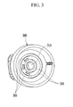
- FIG. 3 is a partial perspective view of a discharge unit of the urea solution pumping system according to the exemplary embodiment of the present inventive concept.
- the upper cover 300 is formed to cover a front surface of the exterior stator over-molding 225, and has an outlet 315 at a center thereof.
- the three-phase terminal 305 through which power is supplied, protrudes and is disposed around the outlet 315, and o-ring grooves 310 are formed based on the outlet 315 at both sides based on the three-phase terminal 305.
- upper motor o-rings 505 of FIG. 5 are sealing members and mounted at the o-ring grooves 310 to block the urea solution flowing through the outlet 315 and an external urea solution from flowing into the three-phase terminal 305.
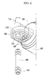
- FIG. 4 is a partial exploded perspective view of the motor and the pump unit in the urea solution pumping system according to the exemplary embodiment of the present inventive concept.
- the pump unit 115 includes the rotating shaft 200, the rotor over-molding 210, the exterior stator over-molding 225, a lower motor o-ring 400, a lower motor cover 405, a pump 410, a pump cover 415, a lower pump cover 420, an inlet 425, fastening bolts 430, and a housing 435.
- the lower motor o-ring 400 is formed in a sealing structure between the stator outside molding 225 and the lower motor cover 405, and the pump 410 sucks an external urea solution through the inlet 425 of the lower pump cover 420 and pumps the sucked urea solution between the rotor 205 and the stator 215, so that the urea solution is pumped through the outlet 315.
- the pump 410 may be a gerotor.
- the fastening bolts 430 are fastened to the exterior stator over-molding 225 while passing through the lower pump cover 420, the exterior stator over-molding 225 is inserted into the housing 435, and a leading end of the housing 435 is bent and fixed to the exterior stator over-molding 225.
- FIG. 5 is a partial cross-sectional view of the pump unit, the motor, and the discharge unit according to the exemplary embodiment of the present inventive concept.
- the pump unit includes a pump unit 552 and a motor 554, and the pump unit 552 sucks a urea solution through the inlet 425 of the lower pump cover 420, while the pump 410 rotates by the rotating shaft 200 to pump the urea solution between the rotor 205 and the stator 215.
- the motor 554 rotates the rotating shaft 200 and the pump 410 through a structure of the stator 215 and the rotor 205, and provides a urea solution flow gap between the rotor 205 and the stator 215.
- the outlet 315 is formed at a part corresponding to the rotating shaft 200 at a center of the upper cover 300, and the outlet adaptor 1112 is integrally formed at a leading end of the upper cover 300.
- a relief valve 500 relieving pressure to an upper side is disposed at an end of the outlet 315 in the outlet adaptor 1112, and a urea solution is discharged to a lower side (a left side of FIG. 5 ).
- FIG. 6 is a partial exploded perspective view of the discharge unit according to the exemplary embodiment of the present inventive concept.
- an outlet adaptor 1112 having the outlet 315 opened to a lower side is integrally formed at a front side of the upper cover 300, and a relief pipe 710, in which the relief valve 500 is disposed, protrudes and is integrally formed on the upper cover 300.
- a pipe-shaped metal port 605 is inserted into the outlet 315 formed at the lower side of the outlet adaptor 1112, a port o-ring 610 as a sealing member is mounted on an outer peripheral surface of the pipe-shaped metal port 605, and the three-phase terminal 305 connecting a power (not shown) to one side of the outlet 315 protrudes in a downward direction and is formed at a lower part of the outlet adaptor 1112.
- a first adaptor o-ring 600 is disposed along a circumference at a lower side of an edge of the outlet adaptor 1112, and the first adaptor o-ring 600 forms a sealing structure with an internal surface of an adaptor insertion recess 715 of FIG. 7 .
- FIG. 7 is a partial perspective view illustrating a state in which the bracket is fastened to the adaptor part in the urea solution pumping system according to the exemplary embodiment of the present inventive concept.
- the adaptor insertion recess 715 is formed on an upper surface of the bracket 105, a lower part of the outlet adaptor 1112 is inserted into the adaptor insertion recess 715, and the clip 705 fixes the outlet adaptor 1112 to the adaptor insertion recess 715.
- the relief pipe 710 extends to an upper part of the outlet adaptor 1112, and the relief valve 500 is disposed at an internal side of the relief pipe 710.
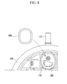
- FIG. 8 is a partial exploded perspective view illustrating a part fastened to the adaptor on the bracket according to the exemplary embodiment of the present inventive concept.
- a second adaptor o-ring 800 is in close contact with a bottom surface of the adaptor insertion recess 715, and the second adaptor o-ring 800 is in close contact with a lower surface of the outlet adaptor 1112 to form a sealing structure between the bracket 105 and the outlet adaptor 1112.
- a power connection hole 805 is formed on the bottom surface of the adaptor insertion recess 715 so that the three-phase terminal 305 protruding from the lower surface of the outlet adaptor 1112 is connected with the power.
- FIG. 9 is a partial exploded perspective view illustrating a fastening structure of the bracket and the thawing unit according to the exemplary embodiment of the present inventive concept.
- the hooks 900 protrude and are integrally formed on the bracket 105, and the hook fastening parts 905, which are fastened to the hook 900 to be fixed, are integrally formed at a side lower portion of the thawing unit 120.
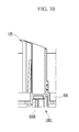
- FIG. 10 is a partial cross-sectional view of the bracket according to the exemplary embodiment of the present inventive concept.
- a sensor unit 1001 is disposed on the bracket 105, the sensor unit 1001 includes a sensor cell 1000, and the sensor cell 1000 is covered by a sealant and the like, and foreign substances such as a urea solution are fundamentally prevented from flowing into the sensor cell 1000 by fixing the sensor cell 1000.
- the sensor unit 1001 may include a temperature sensor, a pressure sensor, or a level sensor.
- FIG. 11 is a partial exploded perspective view of the thawing unit according to the exemplary embodiment of the present inventive concept.
- the thawing unit 120 includes a positive temperature coefficient (PTC) thermistor 1005, a PTC guide 1010, power supply terminal plates 1015, a polyimide adhesive film 1020, and a thawing over-molding 1025.
- PTC positive temperature coefficient
- a recess is formed at a center of the PTC guide 1010, the PTC thermistor 1005 is inserted into and disposed at the recess, and the power supply terminal plates 1015 are in close contact with both surfaces of the PTC guide 1010.
- the polyimide adhesive film 1020 is attached to each of both external surfaces of the power supply terminal plate 1015, and the thawing over-molding 1025 is formed to completely surround an external side of the polyimide adhesive film 1020.
- FIG. 12 is a partial exploded perspective view of the discharge unit according to the exemplary embodiment of the present inventive concept.
- the outlet adaptor 1112 protrudes and is integrally formed at the front side of the upper cover 300
- the relief pipe 710 protrudes and is integrally formed at an upper side of the outlet adaptor 1112
- the relief valve 500 is disposed at an inner side of the relief valve 710.
- the relief valve 500 includes an elastic member 1200 and a check ball 1205, and when the elastic member 1200 elastically supports the check ball 1205 and a pressure of the urea solution pumped through the outlet 315 is equal to or larger than a predetermined value, the urea solution pushes the check ball 1205 and is relieved to the upper side of the outlet adaptor 1112.
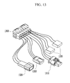
- FIG. 13 is a partial exploded perspective view illustrating a structure of a connector in the urea solution pumping system according to the exemplary embodiment of the present inventive concept.
- a collective connector 1300 is fastened to a lower part of the bracket 105 to be connected to respective elements, and the collective connector 1300 is electrically connected with each of a heater connector 1305, a pressure sensor connector 1310, a motor connector 1315, and a level/temperature sensor connector 1320.
- the heater connector 1305 is electrically connected with the PTC thermistor 1005 of the thawing unit 120, the pressure sensor connector 1310 is electrically connected with the pressure sensor, the motor connector 1315 is electrically connected with the rotor 205 or the stator 215, and the level/temperature sensor connector 1320 is electrically connected with the level sensor and the temperature sensor, respectively.
- the urea solution pump unit according to the present disclosure may improve sealing performance and anti-corrosive performance by adopting the rotor molding and the stator molding formed by mixing engineering plastic and glass fiber.
- the o-ring for sealing is applied to each connection portion to prevent a urea solution from permeating into a power supply system.
- the metal port is applied to the inner side of the outlet, and thus it is possible to improve freezing stability and durability.
- the sensor unit includes a temperature sensor, a level sensor, or a pressure sensor, detailed structures of which are referred to in the publicly disclosed technology.
Landscapes
- Engineering & Computer Science (AREA)
- Chemical & Material Sciences (AREA)
- Chemical Kinetics & Catalysis (AREA)
- Mechanical Engineering (AREA)
- General Engineering & Computer Science (AREA)
- Combustion & Propulsion (AREA)
- Health & Medical Sciences (AREA)
- Toxicology (AREA)
- Power Engineering (AREA)
- Exhaust Gas After Treatment (AREA)
- Structures Of Non-Positive Displacement Pumps (AREA)
Applications Claiming Priority (1)
| Application Number | Priority Date | Filing Date | Title |
|---|---|---|---|
| KR1020150032757A KR101655201B1 (ko) | 2015-03-09 | 2015-03-09 | 요소수 펌프유닛 |
Publications (2)
| Publication Number | Publication Date |
|---|---|
| EP3088694A1 true EP3088694A1 (de) | 2016-11-02 |
| EP3088694B1 EP3088694B1 (de) | 2018-03-21 |
Family
ID=54329452
Family Applications (1)
| Application Number | Title | Priority Date | Filing Date |
|---|---|---|---|
| EP15189982.0A Active EP3088694B1 (de) | 2015-03-09 | 2015-10-15 | Harnstofflösungs-pumpeneinheit |
Country Status (4)
| Country | Link |
|---|---|
| US (1) | US10100693B2 (de) |
| EP (1) | EP3088694B1 (de) |
| KR (1) | KR101655201B1 (de) |
| CN (1) | CN105952517A (de) |
Families Citing this family (17)
| Publication number | Priority date | Publication date | Assignee | Title |
|---|---|---|---|---|
| FR3009586B1 (fr) * | 2013-08-06 | 2015-08-28 | Snecma | Dispositif d'alimentation en ergol de moteur-fusee |
| CN106285851A (zh) * | 2016-09-22 | 2017-01-04 | 凯龙高科技股份有限公司 | 一种计量泵用液路吹扫装置 |
| CN207178011U (zh) * | 2016-10-21 | 2018-04-03 | 天纳克(苏州)排放系统有限公司 | 尿素泵模块 |
| EP3369901B1 (de) * | 2017-03-03 | 2019-10-16 | MEAS France | Harnstoffsensorschutzanordnung und harnstoffsensorsystem |
| KR102261542B1 (ko) | 2017-03-27 | 2021-06-04 | 현대자동차주식회사 | 요소수 펌프 모듈 |
| KR101968318B1 (ko) | 2017-09-28 | 2019-08-13 | 세종공업 주식회사 | 우레아 인젝터로의 과공급량 제어방법 |
| KR102383366B1 (ko) * | 2017-10-18 | 2022-04-06 | 현대자동차주식회사 | 자동차용 요소수 펌프 모듈 |
| DE102017220157B4 (de) * | 2017-11-13 | 2025-02-06 | Hanon Systems Efp Deutschland Gmbh | Wasserpumpe und Verfahren zur Herstellung einer Wasserpumpe |
| CN111322252B (zh) * | 2018-10-30 | 2020-12-22 | 玉环县兴发动力有限公司 | 一种用于尿素的加注泵 |
| CN109372761B (zh) * | 2018-10-30 | 2020-06-30 | 杭州富阳何氏化纤助剂有限公司 | 一种柴油车上使用的尿素加注泵 |
| KR102069764B1 (ko) | 2018-11-29 | 2020-02-24 | 주식회사 화영 | 요소수 공급장치 |
| FR3096738B1 (fr) * | 2019-05-31 | 2021-05-28 | Plastic Omnium Advanced Innovation & Res | Dispositif de fixation pour module de distribution de solution aqueuse contenue dans un réservoir à bord d’un véhicule automobile |
| CN111102048A (zh) * | 2019-12-17 | 2020-05-05 | 凯龙高科技股份有限公司 | 一种scr系统尿素泵的加热解冻控制系统及方法 |
| CN113090521B (zh) * | 2019-12-23 | 2023-03-07 | 西安秦泰汽车排放技术有限公司 | 一种干态非气助式尿素泵的测试系统及其方法 |
| CN111485145B (zh) * | 2020-05-29 | 2021-12-28 | 苏州撼力合金股份有限公司 | 一种力学性能优异的铝合金 |
| KR102374346B1 (ko) * | 2020-10-20 | 2022-03-16 | (주)하이엘 | 차량용 요소수의 결빙 방지장치 |
| CN114542242B (zh) * | 2020-11-26 | 2025-10-28 | 森泰科股份公司 | 液位传感器组件 |
Citations (3)
| Publication number | Priority date | Publication date | Assignee | Title |
|---|---|---|---|---|
| DE102004062603B3 (de) * | 2004-12-24 | 2006-07-27 | Eichenauer Heizelemente Gmbh & Co. Kg | Harnstoff-Dosiersystem für einen Abgasreinigungskatalysator eines Kfz und Ringheizung für ein solches Harnstoff-Dosiersystem |
| US20130000743A1 (en) * | 2011-06-29 | 2013-01-03 | Ti Group Automotive Systems, L.L.C. | Scr fluid distribution and circulation system |
| EP2556870A2 (de) * | 2011-08-08 | 2013-02-13 | TI Group Automotive Systems, L.L.C. | Flüssigkeitsverteilungssystem mit Filtration |
Family Cites Families (4)
| Publication number | Priority date | Publication date | Assignee | Title |
|---|---|---|---|---|
| FR2943744A1 (fr) * | 2009-03-24 | 2010-10-01 | Inergy Automotive Systems Res | Pompe rotative |
| KR101459476B1 (ko) * | 2013-06-04 | 2014-11-07 | 현대자동차 주식회사 | 요소수 펌프유닛 |
| KR101490931B1 (ko) * | 2013-08-13 | 2015-02-06 | 현대자동차 주식회사 | 요소수 펌핑모듈 |
| KR101459680B1 (ko) * | 2014-07-22 | 2014-11-12 | 주식회사 테스크 | 유레아센더 어셈블리 |
-
2015
- 2015-03-09 KR KR1020150032757A patent/KR101655201B1/ko not_active Expired - Fee Related
- 2015-09-17 US US14/857,427 patent/US10100693B2/en active Active
- 2015-10-09 CN CN201510651137.8A patent/CN105952517A/zh active Pending
- 2015-10-15 EP EP15189982.0A patent/EP3088694B1/de active Active
Patent Citations (3)
| Publication number | Priority date | Publication date | Assignee | Title |
|---|---|---|---|---|
| DE102004062603B3 (de) * | 2004-12-24 | 2006-07-27 | Eichenauer Heizelemente Gmbh & Co. Kg | Harnstoff-Dosiersystem für einen Abgasreinigungskatalysator eines Kfz und Ringheizung für ein solches Harnstoff-Dosiersystem |
| US20130000743A1 (en) * | 2011-06-29 | 2013-01-03 | Ti Group Automotive Systems, L.L.C. | Scr fluid distribution and circulation system |
| EP2556870A2 (de) * | 2011-08-08 | 2013-02-13 | TI Group Automotive Systems, L.L.C. | Flüssigkeitsverteilungssystem mit Filtration |
Also Published As
| Publication number | Publication date |
|---|---|
| US20160265406A1 (en) | 2016-09-15 |
| EP3088694B1 (de) | 2018-03-21 |
| CN105952517A (zh) | 2016-09-21 |
| KR101655201B1 (ko) | 2016-09-07 |
| US10100693B2 (en) | 2018-10-16 |
Similar Documents
| Publication | Publication Date | Title |
|---|---|---|
| US10100693B2 (en) | Urea solution pump unit | |
| EP2837785B1 (de) | Pumpenmodul für Harnstofflösung | |
| KR101345972B1 (ko) | 환원제 이송 장치 | |
| EP3263861B1 (de) | Heizstruktur, herstellungsverfahren dafür und pumpenmodul damit | |
| US9874131B2 (en) | Pump module | |
| CN101828012A (zh) | 用于储存还原剂的罐 | |
| KR20110067143A (ko) | 차량용 회전식 펌프 | |
| US10016710B2 (en) | Filter apparatus for a liquid vessel, in particular for aqueous urea solution | |
| KR102383366B1 (ko) | 자동차용 요소수 펌프 모듈 | |
| KR20130115175A (ko) | 차량 엔진용 첨가제 용액을 저장하기 위한 시스템 | |
| CN108603430B (zh) | 用于还原剂的储罐系统 | |
| KR101459476B1 (ko) | 요소수 펌프유닛 | |
| KR101599666B1 (ko) | 플랜지 구조체 및 이를 구비한 펌프 모듈 | |
| KR101604209B1 (ko) | 펌프용 커버 및 이를 구비한 펌프 모듈 | |
| RU2650240C1 (ru) | Устройство для подачи жидкой добавки | |
| CN106150617B (zh) | 尿素喷射组件 | |
| US11852065B2 (en) | Attachment device for a module for dispensing an aqueous solution contained in a tank on board a motor vehicle | |
| CN106150619A (zh) | 尿素喷射组件 | |
| KR101770376B1 (ko) | 요소수 펌프 모듈 | |
| KR101592815B1 (ko) | 펌프용 결합 구조체 및 이를 구비한 펌프 모듈 | |
| CN115585059A (zh) | 用于供应喷射水的装置 | |
| KR101601056B1 (ko) | 차량용 전동식 워터 펌프의 침출수 배출장치 | |
| CN106150618A (zh) | 尿素喷射组件 |
Legal Events
| Date | Code | Title | Description |
|---|---|---|---|
| PUAI | Public reference made under article 153(3) epc to a published international application that has entered the european phase |
Free format text: ORIGINAL CODE: 0009012 |
|
| AK | Designated contracting states |
Kind code of ref document: A1 Designated state(s): AL AT BE BG CH CY CZ DE DK EE ES FI FR GB GR HR HU IE IS IT LI LT LU LV MC MK MT NL NO PL PT RO RS SE SI SK SM TR |
|
| AX | Request for extension of the european patent |
Extension state: BA ME |
|
| 17P | Request for examination filed |
Effective date: 20170502 |
|
| RBV | Designated contracting states (corrected) |
Designated state(s): AL AT BE BG CH CY CZ DE DK EE ES FI FR GB GR HR HU IE IS IT LI LT LU LV MC MK MT NL NO PL PT RO RS SE SI SK SM TR |
|
| 17Q | First examination report despatched |
Effective date: 20170601 |
|
| GRAP | Despatch of communication of intention to grant a patent |
Free format text: ORIGINAL CODE: EPIDOSNIGR1 |
|
| INTG | Intention to grant announced |
Effective date: 20171110 |
|
| GRAS | Grant fee paid |
Free format text: ORIGINAL CODE: EPIDOSNIGR3 |
|
| GRAA | (expected) grant |
Free format text: ORIGINAL CODE: 0009210 |
|
| AK | Designated contracting states |
Kind code of ref document: B1 Designated state(s): AL AT BE BG CH CY CZ DE DK EE ES FI FR GB GR HR HU IE IS IT LI LT LU LV MC MK MT NL NO PL PT RO RS SE SI SK SM TR |
|
| REG | Reference to a national code |
Ref country code: GB Ref legal event code: FG4D |
|
| REG | Reference to a national code |
Ref country code: CH Ref legal event code: EP |
|
| REG | Reference to a national code |
Ref country code: AT Ref legal event code: REF Ref document number: 981357 Country of ref document: AT Kind code of ref document: T Effective date: 20180415 |
|
| REG | Reference to a national code |
Ref country code: IE Ref legal event code: FG4D |
|
| REG | Reference to a national code |
Ref country code: DE Ref legal event code: R096 Ref document number: 602015009027 Country of ref document: DE |
|
| REG | Reference to a national code |
Ref country code: NL Ref legal event code: MP Effective date: 20180321 |
|
| PG25 | Lapsed in a contracting state [announced via postgrant information from national office to epo] |
Ref country code: LT Free format text: LAPSE BECAUSE OF FAILURE TO SUBMIT A TRANSLATION OF THE DESCRIPTION OR TO PAY THE FEE WITHIN THE PRESCRIBED TIME-LIMIT Effective date: 20180321 Ref country code: FI Free format text: LAPSE BECAUSE OF FAILURE TO SUBMIT A TRANSLATION OF THE DESCRIPTION OR TO PAY THE FEE WITHIN THE PRESCRIBED TIME-LIMIT Effective date: 20180321 Ref country code: HR Free format text: LAPSE BECAUSE OF FAILURE TO SUBMIT A TRANSLATION OF THE DESCRIPTION OR TO PAY THE FEE WITHIN THE PRESCRIBED TIME-LIMIT Effective date: 20180321 Ref country code: NO Free format text: LAPSE BECAUSE OF FAILURE TO SUBMIT A TRANSLATION OF THE DESCRIPTION OR TO PAY THE FEE WITHIN THE PRESCRIBED TIME-LIMIT Effective date: 20180621 Ref country code: CY Free format text: LAPSE BECAUSE OF FAILURE TO SUBMIT A TRANSLATION OF THE DESCRIPTION OR TO PAY THE FEE WITHIN THE PRESCRIBED TIME-LIMIT Effective date: 20180321 |
|
| REG | Reference to a national code |
Ref country code: LT Ref legal event code: MG4D |
|
| REG | Reference to a national code |
Ref country code: AT Ref legal event code: MK05 Ref document number: 981357 Country of ref document: AT Kind code of ref document: T Effective date: 20180321 |
|
| PG25 | Lapsed in a contracting state [announced via postgrant information from national office to epo] |
Ref country code: RS Free format text: LAPSE BECAUSE OF FAILURE TO SUBMIT A TRANSLATION OF THE DESCRIPTION OR TO PAY THE FEE WITHIN THE PRESCRIBED TIME-LIMIT Effective date: 20180321 Ref country code: BG Free format text: LAPSE BECAUSE OF FAILURE TO SUBMIT A TRANSLATION OF THE DESCRIPTION OR TO PAY THE FEE WITHIN THE PRESCRIBED TIME-LIMIT Effective date: 20180621 Ref country code: GR Free format text: LAPSE BECAUSE OF FAILURE TO SUBMIT A TRANSLATION OF THE DESCRIPTION OR TO PAY THE FEE WITHIN THE PRESCRIBED TIME-LIMIT Effective date: 20180622 Ref country code: LV Free format text: LAPSE BECAUSE OF FAILURE TO SUBMIT A TRANSLATION OF THE DESCRIPTION OR TO PAY THE FEE WITHIN THE PRESCRIBED TIME-LIMIT Effective date: 20180321 Ref country code: SE Free format text: LAPSE BECAUSE OF FAILURE TO SUBMIT A TRANSLATION OF THE DESCRIPTION OR TO PAY THE FEE WITHIN THE PRESCRIBED TIME-LIMIT Effective date: 20180321 |
|
| REG | Reference to a national code |
Ref country code: FR Ref legal event code: PLFP Year of fee payment: 4 |
|
| PG25 | Lapsed in a contracting state [announced via postgrant information from national office to epo] |
Ref country code: ES Free format text: LAPSE BECAUSE OF FAILURE TO SUBMIT A TRANSLATION OF THE DESCRIPTION OR TO PAY THE FEE WITHIN THE PRESCRIBED TIME-LIMIT Effective date: 20180321 Ref country code: NL Free format text: LAPSE BECAUSE OF FAILURE TO SUBMIT A TRANSLATION OF THE DESCRIPTION OR TO PAY THE FEE WITHIN THE PRESCRIBED TIME-LIMIT Effective date: 20180321 Ref country code: AL Free format text: LAPSE BECAUSE OF FAILURE TO SUBMIT A TRANSLATION OF THE DESCRIPTION OR TO PAY THE FEE WITHIN THE PRESCRIBED TIME-LIMIT Effective date: 20180321 Ref country code: EE Free format text: LAPSE BECAUSE OF FAILURE TO SUBMIT A TRANSLATION OF THE DESCRIPTION OR TO PAY THE FEE WITHIN THE PRESCRIBED TIME-LIMIT Effective date: 20180321 Ref country code: IT Free format text: LAPSE BECAUSE OF FAILURE TO SUBMIT A TRANSLATION OF THE DESCRIPTION OR TO PAY THE FEE WITHIN THE PRESCRIBED TIME-LIMIT Effective date: 20180321 Ref country code: RO Free format text: LAPSE BECAUSE OF FAILURE TO SUBMIT A TRANSLATION OF THE DESCRIPTION OR TO PAY THE FEE WITHIN THE PRESCRIBED TIME-LIMIT Effective date: 20180321 Ref country code: PL Free format text: LAPSE BECAUSE OF FAILURE TO SUBMIT A TRANSLATION OF THE DESCRIPTION OR TO PAY THE FEE WITHIN THE PRESCRIBED TIME-LIMIT Effective date: 20180321 |
|
| PG25 | Lapsed in a contracting state [announced via postgrant information from national office to epo] |
Ref country code: SK Free format text: LAPSE BECAUSE OF FAILURE TO SUBMIT A TRANSLATION OF THE DESCRIPTION OR TO PAY THE FEE WITHIN THE PRESCRIBED TIME-LIMIT Effective date: 20180321 Ref country code: CZ Free format text: LAPSE BECAUSE OF FAILURE TO SUBMIT A TRANSLATION OF THE DESCRIPTION OR TO PAY THE FEE WITHIN THE PRESCRIBED TIME-LIMIT Effective date: 20180321 Ref country code: AT Free format text: LAPSE BECAUSE OF FAILURE TO SUBMIT A TRANSLATION OF THE DESCRIPTION OR TO PAY THE FEE WITHIN THE PRESCRIBED TIME-LIMIT Effective date: 20180321 Ref country code: SM Free format text: LAPSE BECAUSE OF FAILURE TO SUBMIT A TRANSLATION OF THE DESCRIPTION OR TO PAY THE FEE WITHIN THE PRESCRIBED TIME-LIMIT Effective date: 20180321 |
|
| PG25 | Lapsed in a contracting state [announced via postgrant information from national office to epo] |
Ref country code: PT Free format text: LAPSE BECAUSE OF FAILURE TO SUBMIT A TRANSLATION OF THE DESCRIPTION OR TO PAY THE FEE WITHIN THE PRESCRIBED TIME-LIMIT Effective date: 20180723 |
|
| REG | Reference to a national code |
Ref country code: DE Ref legal event code: R097 Ref document number: 602015009027 Country of ref document: DE |
|
| PLBE | No opposition filed within time limit |
Free format text: ORIGINAL CODE: 0009261 |
|
| STAA | Information on the status of an ep patent application or granted ep patent |
Free format text: STATUS: NO OPPOSITION FILED WITHIN TIME LIMIT |
|
| PG25 | Lapsed in a contracting state [announced via postgrant information from national office to epo] |
Ref country code: DK Free format text: LAPSE BECAUSE OF FAILURE TO SUBMIT A TRANSLATION OF THE DESCRIPTION OR TO PAY THE FEE WITHIN THE PRESCRIBED TIME-LIMIT Effective date: 20180321 |
|
| 26N | No opposition filed |
Effective date: 20190102 |
|
| PG25 | Lapsed in a contracting state [announced via postgrant information from national office to epo] |
Ref country code: SI Free format text: LAPSE BECAUSE OF FAILURE TO SUBMIT A TRANSLATION OF THE DESCRIPTION OR TO PAY THE FEE WITHIN THE PRESCRIBED TIME-LIMIT Effective date: 20180321 |
|
| REG | Reference to a national code |
Ref country code: CH Ref legal event code: PL |
|
| REG | Reference to a national code |
Ref country code: BE Ref legal event code: MM Effective date: 20181031 |
|
| PG25 | Lapsed in a contracting state [announced via postgrant information from national office to epo] |
Ref country code: LU Free format text: LAPSE BECAUSE OF NON-PAYMENT OF DUE FEES Effective date: 20181015 Ref country code: MC Free format text: LAPSE BECAUSE OF FAILURE TO SUBMIT A TRANSLATION OF THE DESCRIPTION OR TO PAY THE FEE WITHIN THE PRESCRIBED TIME-LIMIT Effective date: 20180321 |
|
| REG | Reference to a national code |
Ref country code: IE Ref legal event code: MM4A |
|
| PG25 | Lapsed in a contracting state [announced via postgrant information from national office to epo] |
Ref country code: BE Free format text: LAPSE BECAUSE OF NON-PAYMENT OF DUE FEES Effective date: 20181031 Ref country code: CH Free format text: LAPSE BECAUSE OF NON-PAYMENT OF DUE FEES Effective date: 20181031 Ref country code: LI Free format text: LAPSE BECAUSE OF NON-PAYMENT OF DUE FEES Effective date: 20181031 |
|
| PG25 | Lapsed in a contracting state [announced via postgrant information from national office to epo] |
Ref country code: IE Free format text: LAPSE BECAUSE OF NON-PAYMENT OF DUE FEES Effective date: 20181015 |
|
| PG25 | Lapsed in a contracting state [announced via postgrant information from national office to epo] |
Ref country code: MT Free format text: LAPSE BECAUSE OF NON-PAYMENT OF DUE FEES Effective date: 20181015 |
|
| PG25 | Lapsed in a contracting state [announced via postgrant information from national office to epo] |
Ref country code: TR Free format text: LAPSE BECAUSE OF FAILURE TO SUBMIT A TRANSLATION OF THE DESCRIPTION OR TO PAY THE FEE WITHIN THE PRESCRIBED TIME-LIMIT Effective date: 20180321 |
|
| PG25 | Lapsed in a contracting state [announced via postgrant information from national office to epo] |
Ref country code: HU Free format text: LAPSE BECAUSE OF FAILURE TO SUBMIT A TRANSLATION OF THE DESCRIPTION OR TO PAY THE FEE WITHIN THE PRESCRIBED TIME-LIMIT; INVALID AB INITIO Effective date: 20151015 Ref country code: MK Free format text: LAPSE BECAUSE OF NON-PAYMENT OF DUE FEES Effective date: 20180321 |
|
| PG25 | Lapsed in a contracting state [announced via postgrant information from national office to epo] |
Ref country code: IS Free format text: LAPSE BECAUSE OF FAILURE TO SUBMIT A TRANSLATION OF THE DESCRIPTION OR TO PAY THE FEE WITHIN THE PRESCRIBED TIME-LIMIT Effective date: 20180721 |
|
| GBPC | Gb: european patent ceased through non-payment of renewal fee |
Effective date: 20191015 |
|
| PG25 | Lapsed in a contracting state [announced via postgrant information from national office to epo] |
Ref country code: GB Free format text: LAPSE BECAUSE OF NON-PAYMENT OF DUE FEES Effective date: 20191015 |
|
| PGFP | Annual fee paid to national office [announced via postgrant information from national office to epo] |
Ref country code: FR Payment date: 20240909 Year of fee payment: 10 |
|
| PGFP | Annual fee paid to national office [announced via postgrant information from national office to epo] |
Ref country code: DE Payment date: 20240904 Year of fee payment: 10 |