EP3088597A1 - Clothes dryer - Google Patents
Clothes dryer Download PDFInfo
- Publication number
- EP3088597A1 EP3088597A1 EP16163120.5A EP16163120A EP3088597A1 EP 3088597 A1 EP3088597 A1 EP 3088597A1 EP 16163120 A EP16163120 A EP 16163120A EP 3088597 A1 EP3088597 A1 EP 3088597A1
- Authority
- EP
- European Patent Office
- Prior art keywords
- barrel
- airflow passage
- condenser
- passage
- clothes dryer
- Prior art date
- Legal status (The legal status is an assumption and is not a legal conclusion. Google has not performed a legal analysis and makes no representation as to the accuracy of the status listed.)
- Withdrawn
Links
- XLYOFNOQVPJJNP-UHFFFAOYSA-N water Substances O XLYOFNOQVPJJNP-UHFFFAOYSA-N 0.000 claims abstract description 18
- 238000004891 communication Methods 0.000 claims abstract description 15
- 239000000498 cooling water Substances 0.000 claims description 18
- 238000011144 upstream manufacturing Methods 0.000 claims description 4
- 238000005452 bending Methods 0.000 claims description 3
- 230000007423 decrease Effects 0.000 claims description 3
- 238000010438 heat treatment Methods 0.000 abstract description 10
- 238000009833 condensation Methods 0.000 abstract description 7
- 230000005494 condensation Effects 0.000 abstract description 7
- 238000001035 drying Methods 0.000 description 6
- 238000013461 design Methods 0.000 description 2
- 238000000034 method Methods 0.000 description 2
- 238000012545 processing Methods 0.000 description 2
- 238000009825 accumulation Methods 0.000 description 1
- 230000001174 ascending effect Effects 0.000 description 1
- 239000002826 coolant Substances 0.000 description 1
- 238000010586 diagram Methods 0.000 description 1
- 238000012986 modification Methods 0.000 description 1
- 230000004048 modification Effects 0.000 description 1
- 238000005406 washing Methods 0.000 description 1
Images

Classifications
-
- D—TEXTILES; PAPER
- D06—TREATMENT OF TEXTILES OR THE LIKE; LAUNDERING; FLEXIBLE MATERIALS NOT OTHERWISE PROVIDED FOR
- D06F—LAUNDERING, DRYING, IRONING, PRESSING OR FOLDING TEXTILE ARTICLES
- D06F58/00—Domestic laundry dryers
- D06F58/20—General details of domestic laundry dryers
- D06F58/24—Condensing arrangements
-
- D—TEXTILES; PAPER
- D06—TREATMENT OF TEXTILES OR THE LIKE; LAUNDERING; FLEXIBLE MATERIALS NOT OTHERWISE PROVIDED FOR
- D06F—LAUNDERING, DRYING, IRONING, PRESSING OR FOLDING TEXTILE ARTICLES
- D06F25/00—Washing machines with receptacles, e.g. perforated, having a rotary movement, e.g. oscillatory movement, the receptacle serving both for washing and for centrifugally separating water from the laundry and having further drying means, e.g. using hot air
Definitions
- the present invention relates to a clothes dryer, and in particular, to a condensing apparatus of a clothes dryer.
- Clothes dryers generally include machines having only a clothes drying function, and machines integrating a clothes washing function and a clothes drying function.
- a drying principle of the clothes dryer may be basically summarized as follows: With a heating apparatus, dry air is heated into dry hot air, then enters a clothes processing barrel to exchange heat with wet clothes, takes moisture away from the clothes, and becomes relatively wet hot air. The wet hot air subsequently passes through a condensing apparatus. By condensation of the condensing apparatus, moisture in the wet hot air is condensed into water and is discharged through a drainage tube. After the condensation, the air becomes relatively dry cold air, is guided into the heating apparatus again by a fan, becomes dry hot air after heating, and enters another circle. The circle repeats until a drying program ends.
- the condensing apparatus may use various condensation methods.
- a common method is to use water as a cooling medium to exchange heat with drying air; thereby making moisture in hot air condensed and be separated from air.
- Such a condensing apparatus generally has a body in a passage shape, and a cooling water pipe is connected to the body. Wet hot drying air passes the inside of the condensing apparatus from the bottom up. During this period, cooling water flows out from the top down to exchange heat with wet hot air.
- the limit of space that is, due to the limited height of the body of the condensing apparatus, the heat exchange distance between the wet hot air and the cooling water is short.
- the wet hot air ascending at a high speed blows away the water flow after meeting the cooling water, or even blows water droplets into the fan and an air heating apparatus.
- a condenser needs to occupy some space, and therefore, a clothes processing barrel has to be contained within limited space.
- An objective of the present invention is to provide a clothes dryer in a compact structure, where a condenser also has better heat exchange performance and cooling water is not easily blown into a fan or an air heating apparatus.
- a clothes dryer including a barrel for containing clothes, a condenser that is spatially in communication with the barrel, and a fan that enables air to flow from the barrel to the condenser, where the condenser and the barrel share a common wall, and the condenser has an annular airflow passage.
- the clothes dryer may be various machines having a clothes drying function, for example, a machine used only to dry clothes, or a washer-dryer.
- the barrel includes a periphery wall that is substantially cylindrical; the barrel is substantially horizontally or obliquely disposed along an axis thereof; and the common wall that the condenser shares with the barrel is located on the periphery wall of the barrel, and is located above the axis of the barrel. Because the periphery wall of the barrel is cylindrical shaped, space that can be used exists between the periphery wall and a case body. This improvement solution maximizes, within limited space of the case body, the space between the barrel and the condenser by using this space.
- the annular airflow passage is located in a space that is formed by the arc-shaped periphery wall of the barrel and an outer wall of the condenser, and which space is located obliquely above the axis of the barrel and gradually increases in a perpendicular direction due to bending downwards of the periphery wall of the barrel.
- This space is generally vacant in the clothes dryer, or is rarely occupied by another component completely.
- Such design also finely uses the space.
- this sink space provides relatively sufficient perpendicular space to the annular airflow passage, so that the airflow sufficiently descends within the annular airflow passage, and the longer heat exchange distance is achieved.
- the condenser includes an air intake passage, which is in communication with the annular airflow passage, and is located at an upstream of the annular airflow passage; and the condenser includes a cooling water inlet which is located within the air intake passage. Therefore, cooling water is blown away within the air intake passage by an airflow and is mixed with the airflow, so that the heat exchange distance within the annular airflow passage can be used more sufficiently.
- an air inlet of the air intake passage is provided on the periphery wall of the barrel, and the air inlet of the air intake passage and the cooling water inlet are respectively located at two sides of a corresponding barrel ridge that is located perpendicular above an axis of the barrel. In this way, it is not easy for the cooling water to enter the barrel from the air inlet to wet clothes in the barrel.
- the condenser includes an air intake passage, which is in communication with the annular airflow passage, and is located at an upstream of the annular airflow passage, and a flow cross-section of the air intake passage gradually decreases along an air flowing direction.
- an air intake passage can increase a speed at which the airflow enters the annular airflow passage, and enhance heat exchange performance.
- the condenser includes a cooling water inlet, which is close to a narrowest position of the flow cross-section of the air intake passage.
- the cooling water inlet is located near an area with a highest airflow speed, which helps to blow the cooling water into water droplets and better mix the cooling water with the airflow.
- a relatively high airflow speed results in relatively great centrifugal force within the annular airflow passage, so that condensed water is separated from air to attach to a passage wall, and is prevented from entering the fan.
- the air intake passage extends substantially horizontally.
- a straight airflow passage is provided in the middle of the annular airflow passage, where a wall of the straight airflow passage forms an inner wall of the annular airflow passage; an inlet of the straight airflow passage is located at the bottom thereof, and is in communication with the annular airflow passage; and an outlet of the straight airflow passage is located at the top thereof, and is in communication with the fan. After swirling along the annular airflow passage, the airflow descends to reach the bottom and enter the straight airflow passage.
- Such a circuitous airflow path further limits or even prevents the condensed water from entering the fan, and also achieves more sufficient condensation.
- the wall of the straight airflow passage is cylindrical shaped, so that the airflow swirls in the annular airflow passage more smoothly.
- an inlet of the annular airflow passage is close to the top of the annular airflow passage. After entering the annular airflow passage from a relatively high position, the airflow finally enters the straight airflow passage from the bottom. The airflow swirls down; therefore, heat exchange increases, and condensation performance is improved.
- the inlet of the annular airflow passage is provided in a tangent direction of the annular airflow passage.
- High speed airflow from the tangent direction helps to form a swirling airflow within the annular airflow passage, and reduce resistance.
- a condensed water outlet is provided on a barrel wall that is at the bottom of the annular airflow passage. Such design prevents water accumulation, and the condensed water is discharged out of the barrel by using a drainage apparatus.
- the annular airflow passage includes a cylindrical outer wall and a cylindrical inner wall.
- An annular passage located between the cylindrical outer wall and the cylindrical inner wall has small resistance to airflow passing through the annular passage.
- a clothes dryer has a drum 1 and a barrel 2 that are coaxial and are spatially communicated.
- the drum 1 is rotatably installed in the barrel 2.
- Clothes to be dried are contained in the drum 1, and are gradually dried under the action of hot air that enters the barrel 2.
- the drum 1 and the barrel 2 are substantially horizontally installed along their axial direction.
- a condenser 3 is disposed on a periphery wall 21 that is on the top of the barrel 2.
- a fan 4 and an air heating passage 5 are sequentially connected to a downstream of the condenser 3.
- An outlet air of the air heating passage 5 is in communication with a front opening 20 of the barrel 2. Therefore, an air circulation path is formed in the barrel 2, the condenser 3, the fan 4, and the air heating passage 5.
- the condenser 3 includes an outer wall 31.
- the outer wall 31 together with the substantially cylindrical periphery wall 21 of the barrel forms a condensing passage 32.
- the condensing passage 32 includes an air intake passage 34, and an annular airflow passage 35 located at a downstream of the air intake passage 34.
- the air intake passage 34 is in communication with the annular airflow passage 35.
- the annular airflow passage 35 is located in a space that is formed by the arc-shaped periphery wall 21 of the barrel and the outer wall 31 of the condenser, and which space is located obliquely above an axis 22 of the barrel 2 and gradually increases in a perpendicular direction due to bending downwards of the periphery wall 21 of the barrel.
- the air intake passage 34 extends substantially horizontally, and a flow cross-section of the air intake passage gradually decreases along an air flowing direction.
- a cooling water inlet 36 is located within the air intake passage 34, and is close to a narrowest position of the flow cross-section of the air intake passage 34.
- An air inlet 33 of the air intake passage 34 is provided on the periphery wall 21 of the barrel, and the air inlet 33 of the air intake passage and the cooling water inlet 36 are respectively located at two sides of a corresponding barrel ridge 23 that is located perpendicular above the axis 22 of the barrel 2.
- An annular passage 35 includes a cylindrical outer wall 351 and a cylindrical inner wall 352, where the outer wall 351 is a part of the outer wall 31 of the condenser, and a straight airflow passage 37 is formed within the inner wall 352.
- An inlet 371 of the straight airflow passage 37 is located at the bottom thereof, and is in communication with the annular airflow passage 35; and an outlet 372 of the straight airflow passage is located at the top thereof, and is in communication with the fan 4.
- An inlet 353 of the annular airflow passage 35 is close to the top of the annular airflow passage, and is provided towards a tangent direction of the annular airflow passage 35.
- the inlet 353 of the annular airflow passage 353 is connected to the air intake passage 34.
- a condensed water outlet 38 is provided at the bottom of the annular airflow passage 35 and on the periphery wall 21 of the barrel. Therefore, condensed water is discharged from the condensed water outlet 38 into the barrel 2.
Landscapes
- Engineering & Computer Science (AREA)
- Textile Engineering (AREA)
- Detail Structures Of Washing Machines And Dryers (AREA)
Abstract
Description
- The present invention relates to a clothes dryer, and in particular, to a condensing apparatus of a clothes dryer.
- Clothes dryers generally include machines having only a clothes drying function, and machines integrating a clothes washing function and a clothes drying function. A drying principle of the clothes dryer may be basically summarized as follows: With a heating apparatus, dry air is heated into dry hot air, then enters a clothes processing barrel to exchange heat with wet clothes, takes moisture away from the clothes, and becomes relatively wet hot air. The wet hot air subsequently passes through a condensing apparatus. By condensation of the condensing apparatus, moisture in the wet hot air is condensed into water and is discharged through a drainage tube. After the condensation, the air becomes relatively dry cold air, is guided into the heating apparatus again by a fan, becomes dry hot air after heating, and enters another circle. The circle repeats until a drying program ends.
- The condensing apparatus may use various condensation methods. A common method is to use water as a cooling medium to exchange heat with drying air; thereby making moisture in hot air condensed and be separated from air. Such a condensing apparatus generally has a body in a passage shape, and a cooling water pipe is connected to the body. Wet hot drying air passes the inside of the condensing apparatus from the bottom up. During this period, cooling water flows out from the top down to exchange heat with wet hot air. Generally, due to the limit of space, that is, due to the limited height of the body of the condensing apparatus, the heat exchange distance between the wet hot air and the cooling water is short. In addition, the wet hot air ascending at a high speed blows away the water flow after meeting the cooling water, or even blows water droplets into the fan and an air heating apparatus. In addition, a condenser needs to occupy some space, and therefore, a clothes processing barrel has to be contained within limited space.
- An objective of the present invention is to provide a clothes dryer in a compact structure, where a condenser also has better heat exchange performance and cooling water is not easily blown into a fan or an air heating apparatus.
- To achieve the foregoing objective, a technical solution used in the present invention is as follows: A clothes dryer is provided, including a barrel for containing clothes, a condenser that is spatially in communication with the barrel, and a fan that enables air to flow from the barrel to the condenser, where the condenser and the barrel share a common wall, and the condenser has an annular airflow passage.
- The clothes dryer may be various machines having a clothes drying function, for example, a machine used only to dry clothes, or a washer-dryer.
- Compared with the prior art, because the condenser is integrated with the barrel, space is more compact, and the annular airflow passage provides a longer heat exchange distance, so that condensation efficiency is improved. Swirling airflow forces condensed water to be thrown on a wall of the annular airflow passage under the action of centrifugal force; therefore, the condensed water is not easily brought into a fan and an air heating apparatus by the airflow.
- As a preferable improvement solution, the barrel includes a periphery wall that is substantially cylindrical; the barrel is substantially horizontally or obliquely disposed along an axis thereof; and the common wall that the condenser shares with the barrel is located on the periphery wall of the barrel, and is located above the axis of the barrel. Because the periphery wall of the barrel is cylindrical shaped, space that can be used exists between the periphery wall and a case body. This improvement solution maximizes, within limited space of the case body, the space between the barrel and the condenser by using this space.
- As a possible improvement solution of the present invention, the annular airflow passage is located in a space that is formed by the arc-shaped periphery wall of the barrel and an outer wall of the condenser, and which space is located obliquely above the axis of the barrel and gradually increases in a perpendicular direction due to bending downwards of the periphery wall of the barrel. This space is generally vacant in the clothes dryer, or is rarely occupied by another component completely. Such design also finely uses the space. Moreover, this sink space provides relatively sufficient perpendicular space to the annular airflow passage, so that the airflow sufficiently descends within the annular airflow passage, and the longer heat exchange distance is achieved.
- As a further improvement of the present invention, the condenser includes an air intake passage, which is in communication with the annular airflow passage, and is located at an upstream of the annular airflow passage; and the condenser includes a cooling water inlet which is located within the air intake passage. Therefore, cooling water is blown away within the air intake passage by an airflow and is mixed with the airflow, so that the heat exchange distance within the annular airflow passage can be used more sufficiently.
- As a further improvement of the present invention, an air inlet of the air intake passage is provided on the periphery wall of the barrel, and the air inlet of the air intake passage and the cooling water inlet are respectively located at two sides of a corresponding barrel ridge that is located perpendicular above an axis of the barrel. In this way, it is not easy for the cooling water to enter the barrel from the air inlet to wet clothes in the barrel.
- As a further improvement of the present invention, the condenser includes an air intake passage, which is in communication with the annular airflow passage, and is located at an upstream of the annular airflow passage, and a flow cross-section of the air intake passage gradually decreases along an air flowing direction. Such an air intake passage can increase a speed at which the airflow enters the annular airflow passage, and enhance heat exchange performance.
- As a further improvement of the present invention, the condenser includes a cooling water inlet, which is close to a narrowest position of the flow cross-section of the air intake passage. The cooling water inlet is located near an area with a highest airflow speed, which helps to blow the cooling water into water droplets and better mix the cooling water with the airflow. Moreover, a relatively high airflow speed results in relatively great centrifugal force within the annular airflow passage, so that condensed water is separated from air to attach to a passage wall, and is prevented from entering the fan.
- As a further improvement of the present invention, the air intake passage extends substantially horizontally.
- As a further improvement of the present invention, a straight airflow passage is provided in the middle of the annular airflow passage, where a wall of the straight airflow passage forms an inner wall of the annular airflow passage; an inlet of the straight airflow passage is located at the bottom thereof, and is in communication with the annular airflow passage; and an outlet of the straight airflow passage is located at the top thereof, and is in communication with the fan. After swirling along the annular airflow passage, the airflow descends to reach the bottom and enter the straight airflow passage. Such a circuitous airflow path further limits or even prevents the condensed water from entering the fan, and also achieves more sufficient condensation.
- As a further improvement of the present invention, the wall of the straight airflow passage is cylindrical shaped, so that the airflow swirls in the annular airflow passage more smoothly.
- As a further improvement of the present invention, an inlet of the annular airflow passage is close to the top of the annular airflow passage. After entering the annular airflow passage from a relatively high position, the airflow finally enters the straight airflow passage from the bottom. The airflow swirls down; therefore, heat exchange increases, and condensation performance is improved.
- As a further improvement of the present invention, the inlet of the annular airflow passage is provided in a tangent direction of the annular airflow passage. High speed airflow from the tangent direction helps to form a swirling airflow within the annular airflow passage, and reduce resistance.
- As a further improvement of the present invention, a condensed water outlet is provided on a barrel wall that is at the bottom of the annular airflow passage. Such design prevents water accumulation, and the condensed water is discharged out of the barrel by using a drainage apparatus.
- As a further improvement of the present invention, the annular airflow passage includes a cylindrical outer wall and a cylindrical inner wall. An annular passage located between the cylindrical outer wall and the cylindrical inner wall has small resistance to airflow passing through the annular passage.
- A preferred embodiment of the present invention is now further described as follows with reference to the accompanying drawing, wherein:
- FIG. 1
- is a schematic diagram of a barrel and a condenser of a clothes dryer;
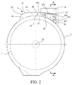
- FIG. 2
- is a cross sectional schematic view of the barrel, the condenser, and a fan of the clothes dryer; and
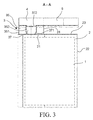
- FIG. 3
- is a sectional view along an A-A direction of
FIG. 2 . - As shown in
FIG. 1 to FIG. 3 , a clothes dryer has adrum 1 and abarrel 2 that are coaxial and are spatially communicated. Thedrum 1 is rotatably installed in thebarrel 2. Clothes to be dried are contained in thedrum 1, and are gradually dried under the action of hot air that enters thebarrel 2. - The
drum 1 and thebarrel 2 are substantially horizontally installed along their axial direction. Acondenser 3 is disposed on aperiphery wall 21 that is on the top of thebarrel 2. Afan 4 and anair heating passage 5 are sequentially connected to a downstream of thecondenser 3. An outlet air of theair heating passage 5 is in communication with a front opening 20 of thebarrel 2. Therefore, an air circulation path is formed in thebarrel 2, thecondenser 3, thefan 4, and theair heating passage 5. - The
condenser 3 includes anouter wall 31. Theouter wall 31 together with the substantiallycylindrical periphery wall 21 of the barrel forms a condensingpassage 32. The condensingpassage 32 includes anair intake passage 34, and anannular airflow passage 35 located at a downstream of theair intake passage 34. Theair intake passage 34 is in communication with theannular airflow passage 35. - The
annular airflow passage 35 is located in a space that is formed by the arc-shapedperiphery wall 21 of the barrel and theouter wall 31 of the condenser, and which space is located obliquely above anaxis 22 of thebarrel 2 and gradually increases in a perpendicular direction due to bending downwards of theperiphery wall 21 of the barrel. - As shown in
FIG. 1 andFIG. 2 , theair intake passage 34 extends substantially horizontally, and a flow cross-section of the air intake passage gradually decreases along an air flowing direction. A coolingwater inlet 36 is located within theair intake passage 34, and is close to a narrowest position of the flow cross-section of theair intake passage 34. Anair inlet 33 of theair intake passage 34 is provided on theperiphery wall 21 of the barrel, and theair inlet 33 of the air intake passage and the coolingwater inlet 36 are respectively located at two sides of acorresponding barrel ridge 23 that is located perpendicular above theaxis 22 of thebarrel 2. - An
annular passage 35 includes a cylindricalouter wall 351 and a cylindricalinner wall 352, where theouter wall 351 is a part of theouter wall 31 of the condenser, and astraight airflow passage 37 is formed within theinner wall 352. Aninlet 371 of thestraight airflow passage 37 is located at the bottom thereof, and is in communication with theannular airflow passage 35; and anoutlet 372 of the straight airflow passage is located at the top thereof, and is in communication with thefan 4. Aninlet 353 of theannular airflow passage 35 is close to the top of the annular airflow passage, and is provided towards a tangent direction of theannular airflow passage 35. Theinlet 353 of theannular airflow passage 353 is connected to theair intake passage 34. - A
condensed water outlet 38 is provided at the bottom of theannular airflow passage 35 and on theperiphery wall 21 of the barrel. Therefore, condensed water is discharged from thecondensed water outlet 38 into thebarrel 2. - Various specific embodiments described in the foregoing and shown in accompanying drawings are only used for illustrating the present invention, and are not regarded as the entirety of the present invention. Within the scope of the basic technical thought of the present invention, any types of modifications to the present invention made by persons ordinarily skilled in the art fall within the protection scope of the present invention.
Claims (14)
- A clothes dryer, comprising a barrel (2) for containing clothes, a condenser (3) that is spatially in communication with the barrel, and a fan (4) that enables air to flow from the barrel to the condenser, characterized in that: the condenser (3) and the barrel (2) share a common wall (21), and the condenser (3) has an annular airflow passage (35).
- The clothes dryer according to claim 1, characterized in that: the barrel (2) comprises a periphery wall (21) that is substantially cylindrical; the barrel (2) is substantially horizontally or obliquely disposed along an axis (22) thereof; and the common wall (21) that the condenser (3) shares with the barrel (2) is located on the periphery wall (21) of the barrel, and is located above the axis (22) of the barrel.
- The clothes dryer according to claim 2, characterized in that: the annular airflow passage (35) is located in a space that is formed by the arc-shaped periphery wall (21) of the barrel and an outer wall (31) of the condenser, and which space is located obliquely above the axis (22) of the barrel and gradually increases in a perpendicular direction due to bending downwards of the periphery wall (21) of the barrel.
- The clothes dryer according to claim 1, characterized in that: the condenser (3) comprises an air intake passage (34), which is in communication with the annular airflow passage (35), and is located at an upstream of the annular airflow passage; and the condenser comprises a cooling water inlet (36) which (36) is located within the air intake passage (34).
- The clothes dryer according to claim 4, characterized in that: an air inlet (33) of the air intake passage (34) is provided on the periphery wall (21) of the barrel, and the air inlet (33) of the air intake passage and the cooling water inlet (36) are respectively located at two sides of a corresponding barrel ridge (23) that is located perpendicular above an axis (22) of the barrel (2).
- The clothes dryer according to claim 1, characterized in that: the condenser (3) comprises an air intake passage (34), which is in communication with the annular airflow passage (35), and is located at an upstream of the annular airflow passage (35), and a flow cross-section of the air intake passage (34) gradually decreases along an air flowing direction.
- The clothes dryer according to claim 6, characterized in that: the condenser (3) comprises a cooling water inlet (36), which is close to a narrowest position of the flow cross-section of the air intake passage (34).
- The clothes dryer according to any one of claims 4 to 7, characterized in that: the air intake passage (34) extends substantially horizontally.
- The clothes dryer according to claim 1, characterized in that: a straight airflow passage (37) is provided in the middle of the annular airflow passage (35), wherein a wall (352) of the straight airflow passage forms an inner wall (352) of the annular airflow passage; an inlet (371) of the straight airflow passage is located at the bottom thereof, and is in communication with the annular airflow passage (35); and an outlet (372) of the straight airflow passage is located at the top thereof, and is in communication with the fan (4).
- The clothes dryer according to claim 9, characterized in that: the wall (352) of the straight airflow passage (37) is cylindrical shaped.
- The clothes dryer according to claim 9, characterized in that: an inlet (353) of the annular airflow passage (35) is close to the top of the annular airflow passage (35).
- The clothes dryer according to claim 11, characterized in that: the inlet (353) of the annular airflow passage (35) is provided in a tangent direction of the annular airflow passage (35).
- The clothes dryer according to claim 1, characterized in that: a condensed water outlet (38) is provided on a barrel wall (21) that is at the bottom of the annular airflow passage (35).
- The clothes dryer according to claim 1, characterized in that: the annular airflow passage (35) comprises a cylindrical outer wall (351) and a cylindrical inner wall (352).
Applications Claiming Priority (1)
| Application Number | Priority Date | Filing Date | Title |
|---|---|---|---|
| CN201510213145.4A CN106192325B (en) | 2015-04-29 | 2015-04-29 | Electric clothes dryer |
Publications (1)
| Publication Number | Publication Date |
|---|---|
| EP3088597A1 true EP3088597A1 (en) | 2016-11-02 |
Family
ID=55642349
Family Applications (1)
| Application Number | Title | Priority Date | Filing Date |
|---|---|---|---|
| EP16163120.5A Withdrawn EP3088597A1 (en) | 2015-04-29 | 2016-03-31 | Clothes dryer |
Country Status (2)
| Country | Link |
|---|---|
| EP (1) | EP3088597A1 (en) |
| CN (1) | CN106192325B (en) |
Cited By (4)
| Publication number | Priority date | Publication date | Assignee | Title |
|---|---|---|---|---|
| CN109023831A (en) * | 2017-06-08 | 2018-12-18 | 无锡小天鹅股份有限公司 | Washing-drying integral machine |
| CN110835832A (en) * | 2019-11-13 | 2020-02-25 | 苏州尼昂科技有限公司 | Condenser structure of a washing machine and drying water cooling system |
| CN111809339A (en) * | 2019-04-11 | 2020-10-23 | 青岛海尔洗衣机有限公司 | A wall-mounted washing machine |
| CN114481575A (en) * | 2021-12-24 | 2022-05-13 | 海尔智家股份有限公司 | Drying cylinder and dryer |
Families Citing this family (5)
| Publication number | Priority date | Publication date | Assignee | Title |
|---|---|---|---|---|
| CN110528236A (en) * | 2018-05-24 | 2019-12-03 | 博西华电器(江苏)有限公司 | clothes dryer |
| CN110806095A (en) * | 2019-10-15 | 2020-02-18 | 无锡小天鹅电器有限公司 | Condensers and Clothes Treatment Devices |
| CN114438757B (en) * | 2020-10-30 | 2023-11-07 | 无锡小天鹅电器有限公司 | Clothes treatment equipment and exhaust condenser |
| CN114657740B (en) * | 2022-03-22 | 2023-12-01 | 无锡小天鹅电器有限公司 | A condenser and clothing treatment equipment |
| CN116005428B (en) * | 2023-01-04 | 2025-11-21 | 珠海格力电器股份有限公司 | Clothes treatment device and washing and drying integrated machine with same |
Citations (6)
| Publication number | Priority date | Publication date | Assignee | Title |
|---|---|---|---|---|
| EP1486605A1 (en) * | 2003-06-13 | 2004-12-15 | Samsung Electronics Co., Ltd. | Washing machine |
| EP1544342A2 (en) * | 2003-12-18 | 2005-06-22 | Lg Electronics Inc. | Washing machine with drying function and method of controlling the same |
| EP1688524A1 (en) * | 2005-02-03 | 2006-08-09 | Lg Electronics Inc. | Washing-drying/drying machine with a condensing device |
| WO2012053751A1 (en) * | 2010-10-19 | 2012-04-26 | Lg Electronics Inc. | Washing machine and control method thereof |
| WO2013151345A2 (en) * | 2012-04-06 | 2013-10-10 | Lg Electronics Inc. | Laundry machine and method for controlling the same |
| EP2883487A1 (en) * | 2013-12-13 | 2015-06-17 | BSH Hausgeräte GmbH | Drying machine |
Family Cites Families (2)
| Publication number | Priority date | Publication date | Assignee | Title |
|---|---|---|---|---|
| CN2414375Y (en) * | 1999-12-21 | 2001-01-10 | 张元跃 | Double-cavity directional radiator |
| CN202116896U (en) * | 2011-03-31 | 2012-01-18 | 无锡小天鹅股份有限公司 | Drying and condensing device of washing and drying integrating machine |
-
2015
- 2015-04-29 CN CN201510213145.4A patent/CN106192325B/en not_active Expired - Fee Related
-
2016
- 2016-03-31 EP EP16163120.5A patent/EP3088597A1/en not_active Withdrawn
Patent Citations (6)
| Publication number | Priority date | Publication date | Assignee | Title |
|---|---|---|---|---|
| EP1486605A1 (en) * | 2003-06-13 | 2004-12-15 | Samsung Electronics Co., Ltd. | Washing machine |
| EP1544342A2 (en) * | 2003-12-18 | 2005-06-22 | Lg Electronics Inc. | Washing machine with drying function and method of controlling the same |
| EP1688524A1 (en) * | 2005-02-03 | 2006-08-09 | Lg Electronics Inc. | Washing-drying/drying machine with a condensing device |
| WO2012053751A1 (en) * | 2010-10-19 | 2012-04-26 | Lg Electronics Inc. | Washing machine and control method thereof |
| WO2013151345A2 (en) * | 2012-04-06 | 2013-10-10 | Lg Electronics Inc. | Laundry machine and method for controlling the same |
| EP2883487A1 (en) * | 2013-12-13 | 2015-06-17 | BSH Hausgeräte GmbH | Drying machine |
Cited By (6)
| Publication number | Priority date | Publication date | Assignee | Title |
|---|---|---|---|---|
| CN109023831A (en) * | 2017-06-08 | 2018-12-18 | 无锡小天鹅股份有限公司 | Washing-drying integral machine |
| CN109023831B (en) * | 2017-06-08 | 2021-02-26 | 无锡小天鹅电器有限公司 | Washing and drying integrated machine |
| CN111809339A (en) * | 2019-04-11 | 2020-10-23 | 青岛海尔洗衣机有限公司 | A wall-mounted washing machine |
| CN111809339B (en) * | 2019-04-11 | 2023-06-13 | 青岛海尔洗衣机有限公司 | A wall-mounted washing machine |
| CN110835832A (en) * | 2019-11-13 | 2020-02-25 | 苏州尼昂科技有限公司 | Condenser structure of a washing machine and drying water cooling system |
| CN114481575A (en) * | 2021-12-24 | 2022-05-13 | 海尔智家股份有限公司 | Drying cylinder and dryer |
Also Published As
| Publication number | Publication date |
|---|---|
| CN106192325A (en) | 2016-12-07 |
| CN106192325B (en) | 2020-06-12 |
Similar Documents
| Publication | Publication Date | Title |
|---|---|---|
| EP3088598B1 (en) | Clothes dryer | |
| CN106192325B (en) | Electric clothes dryer | |
| EP2883487B1 (en) | Drying machine | |
| EP2702199B1 (en) | Heat pump laundry dryer | |
| EP2775028A2 (en) | Laundry treating apparatus | |
| EP2702198B1 (en) | Heat pump laundry dryer | |
| CN105463804B (en) | clothes dryer | |
| CN206346058U (en) | For the condenser of clothes treatment device and the clothes treatment device with it | |
| CN107164914A (en) | Wall-mounted device for clothing processing | |
| CN104727061A (en) | Drum Type Washing Machine Having Dryer Therein | |
| CN103201424A (en) | Thermoelectric heat pump laundry dryer | |
| EP3081688A2 (en) | Electrical household appliance | |
| CN105780425A (en) | Washing machine and drying device thereof | |
| EP3396055B1 (en) | Clothes dryer including condensing apparatus | |
| KR100442400B1 (en) | Condensing apparatus for drum type washing/drying machine | |
| CN214142944U (en) | Washing machine barrel structure and washing machine with same | |
| CN206887489U (en) | Wall-mounted device for clothing processing | |
| CN114790630A (en) | Washing and drying integrated machine and condensation air duct thereof | |
| CN107988771B (en) | clothes dryer | |
| CN109295653B (en) | Washing and drying integrated machine and condenser thereof | |
| CN106087365A (en) | Heat pump clothes dryer or heat pump washing-drying integral machine | |
| CN208907181U (en) | Condenser for washing machine and washing machine | |
| CN219908332U (en) | Condenser, drying device and clothes treatment equipment | |
| KR20230041469A (en) | Moisture condensation module | |
| CN106894210A (en) | Dryer |
Legal Events
| Date | Code | Title | Description |
|---|---|---|---|
| PUAI | Public reference made under article 153(3) epc to a published international application that has entered the european phase |
Free format text: ORIGINAL CODE: 0009012 |
|
| AK | Designated contracting states |
Kind code of ref document: A1 Designated state(s): AL AT BE BG CH CY CZ DE DK EE ES FI FR GB GR HR HU IE IS IT LI LT LU LV MC MK MT NL NO PL PT RO RS SE SI SK SM TR |
|
| AX | Request for extension of the european patent |
Extension state: BA ME |
|
| RIN1 | Information on inventor provided before grant (corrected) |
Inventor name: LI, MAOYIN Inventor name: ZHANG, QI Inventor name: WANG, YONGJIA Inventor name: XU, YONGGANG |
|
| STAA | Information on the status of an ep patent application or granted ep patent |
Free format text: STATUS: THE APPLICATION IS DEEMED TO BE WITHDRAWN |
|
| 18D | Application deemed to be withdrawn |
Effective date: 20170503 |