EP3088316A1 - Label winding device and printing system - Google Patents
Label winding device and printing system Download PDFInfo
- Publication number
- EP3088316A1 EP3088316A1 EP16165897.6A EP16165897A EP3088316A1 EP 3088316 A1 EP3088316 A1 EP 3088316A1 EP 16165897 A EP16165897 A EP 16165897A EP 3088316 A1 EP3088316 A1 EP 3088316A1
- Authority
- EP
- European Patent Office
- Prior art keywords
- waste
- label
- winder
- winding device
- winding
- Prior art date
- Legal status (The legal status is an assumption and is not a legal conclusion. Google has not performed a legal analysis and makes no representation as to the accuracy of the status listed.)
- Granted
Links
- 238000004804 winding Methods 0.000 title claims abstract description 149
- 239000002699 waste material Substances 0.000 claims abstract description 259
- 238000001514 detection method Methods 0.000 claims abstract description 20
- 238000000926 separation method Methods 0.000 claims abstract description 14
- 238000009434 installation Methods 0.000 claims description 6
- 238000003860 storage Methods 0.000 description 6
- 238000000034 method Methods 0.000 description 5
- 230000005540 biological transmission Effects 0.000 description 4
- 238000007796 conventional method Methods 0.000 description 4
- 238000005520 cutting process Methods 0.000 description 4
- 238000010586 diagram Methods 0.000 description 4
- 230000003014 reinforcing effect Effects 0.000 description 4
- 238000004519 manufacturing process Methods 0.000 description 3
- 230000007423 decrease Effects 0.000 description 2
- 230000000903 blocking effect Effects 0.000 description 1
- 239000000463 material Substances 0.000 description 1
- 238000012544 monitoring process Methods 0.000 description 1
- 230000002787 reinforcement Effects 0.000 description 1
- 238000011144 upstream manufacturing Methods 0.000 description 1
Images


Classifications
-
- B—PERFORMING OPERATIONS; TRANSPORTING
- B41—PRINTING; LINING MACHINES; TYPEWRITERS; STAMPS
- B41J—TYPEWRITERS; SELECTIVE PRINTING MECHANISMS, i.e. MECHANISMS PRINTING OTHERWISE THAN FROM A FORME; CORRECTION OF TYPOGRAPHICAL ERRORS
- B41J15/00—Devices or arrangements of selective printing mechanisms, e.g. ink-jet printers or thermal printers, specially adapted for supporting or handling copy material in continuous form, e.g. webs
- B41J15/16—Means for tensioning or winding the web
-
- B—PERFORMING OPERATIONS; TRANSPORTING
- B31—MAKING ARTICLES OF PAPER, CARDBOARD OR MATERIAL WORKED IN A MANNER ANALOGOUS TO PAPER; WORKING PAPER, CARDBOARD OR MATERIAL WORKED IN A MANNER ANALOGOUS TO PAPER
- B31D—MAKING ARTICLES OF PAPER, CARDBOARD OR MATERIAL WORKED IN A MANNER ANALOGOUS TO PAPER, NOT PROVIDED FOR IN SUBCLASSES B31B OR B31C
- B31D1/00—Multiple-step processes for making flat articles ; Making flat articles
- B31D1/02—Multiple-step processes for making flat articles ; Making flat articles the articles being labels or tags
- B31D1/021—Making adhesive labels having a multilayered structure, e.g. provided on carrier webs
-
- B—PERFORMING OPERATIONS; TRANSPORTING
- B31—MAKING ARTICLES OF PAPER, CARDBOARD OR MATERIAL WORKED IN A MANNER ANALOGOUS TO PAPER; WORKING PAPER, CARDBOARD OR MATERIAL WORKED IN A MANNER ANALOGOUS TO PAPER
- B31D—MAKING ARTICLES OF PAPER, CARDBOARD OR MATERIAL WORKED IN A MANNER ANALOGOUS TO PAPER, NOT PROVIDED FOR IN SUBCLASSES B31B OR B31C
- B31D1/00—Multiple-step processes for making flat articles ; Making flat articles
- B31D1/02—Multiple-step processes for making flat articles ; Making flat articles the articles being labels or tags
- B31D1/027—Multiple-step processes for making flat articles ; Making flat articles the articles being labels or tags involving, marking, printing or coding
-
- B—PERFORMING OPERATIONS; TRANSPORTING
- B41—PRINTING; LINING MACHINES; TYPEWRITERS; STAMPS
- B41J—TYPEWRITERS; SELECTIVE PRINTING MECHANISMS, i.e. MECHANISMS PRINTING OTHERWISE THAN FROM A FORME; CORRECTION OF TYPOGRAPHICAL ERRORS
- B41J3/00—Typewriters or selective printing or marking mechanisms characterised by the purpose for which they are constructed
- B41J3/407—Typewriters or selective printing or marking mechanisms characterised by the purpose for which they are constructed for marking on special material
- B41J3/4075—Tape printers; Label printers
-
- B—PERFORMING OPERATIONS; TRANSPORTING
- B65—CONVEYING; PACKING; STORING; HANDLING THIN OR FILAMENTARY MATERIAL
- B65C—LABELLING OR TAGGING MACHINES, APPARATUS, OR PROCESSES
- B65C9/00—Details of labelling machines or apparatus
- B65C9/0015—Preparing the labels or articles, e.g. smoothing, removing air bubbles
-
- B—PERFORMING OPERATIONS; TRANSPORTING
- B65—CONVEYING; PACKING; STORING; HANDLING THIN OR FILAMENTARY MATERIAL
- B65C—LABELLING OR TAGGING MACHINES, APPARATUS, OR PROCESSES
- B65C9/00—Details of labelling machines or apparatus
- B65C9/40—Controls; Safety devices
-
- B—PERFORMING OPERATIONS; TRANSPORTING
- B65—CONVEYING; PACKING; STORING; HANDLING THIN OR FILAMENTARY MATERIAL
- B65H—HANDLING THIN OR FILAMENTARY MATERIAL, e.g. SHEETS, WEBS, CABLES
- B65H23/00—Registering, tensioning, smoothing or guiding webs
- B65H23/04—Registering, tensioning, smoothing or guiding webs longitudinally
- B65H23/048—Registering, tensioning, smoothing or guiding webs longitudinally by positively actuated movable bars or rollers
-
- B—PERFORMING OPERATIONS; TRANSPORTING
- B65—CONVEYING; PACKING; STORING; HANDLING THIN OR FILAMENTARY MATERIAL
- B65H—HANDLING THIN OR FILAMENTARY MATERIAL, e.g. SHEETS, WEBS, CABLES
- B65H23/00—Registering, tensioning, smoothing or guiding webs
- B65H23/04—Registering, tensioning, smoothing or guiding webs longitudinally
- B65H23/18—Registering, tensioning, smoothing or guiding webs longitudinally by controlling or regulating the web-advancing mechanism, e.g. mechanism acting on the running web
- B65H23/195—Registering, tensioning, smoothing or guiding webs longitudinally by controlling or regulating the web-advancing mechanism, e.g. mechanism acting on the running web in winding mechanisms or in connection with winding operations
- B65H23/1955—Registering, tensioning, smoothing or guiding webs longitudinally by controlling or regulating the web-advancing mechanism, e.g. mechanism acting on the running web in winding mechanisms or in connection with winding operations and controlling web tension
-
- B—PERFORMING OPERATIONS; TRANSPORTING
- B65—CONVEYING; PACKING; STORING; HANDLING THIN OR FILAMENTARY MATERIAL
- B65H—HANDLING THIN OR FILAMENTARY MATERIAL, e.g. SHEETS, WEBS, CABLES
- B65H23/00—Registering, tensioning, smoothing or guiding webs
- B65H23/04—Registering, tensioning, smoothing or guiding webs longitudinally
- B65H23/18—Registering, tensioning, smoothing or guiding webs longitudinally by controlling or regulating the web-advancing mechanism, e.g. mechanism acting on the running web
- B65H23/195—Registering, tensioning, smoothing or guiding webs longitudinally by controlling or regulating the web-advancing mechanism, e.g. mechanism acting on the running web in winding mechanisms or in connection with winding operations
- B65H23/198—Registering, tensioning, smoothing or guiding webs longitudinally by controlling or regulating the web-advancing mechanism, e.g. mechanism acting on the running web in winding mechanisms or in connection with winding operations motor-controlled (Controlling electrical drive motors therefor)
-
- B—PERFORMING OPERATIONS; TRANSPORTING
- B65—CONVEYING; PACKING; STORING; HANDLING THIN OR FILAMENTARY MATERIAL
- B65H—HANDLING THIN OR FILAMENTARY MATERIAL, e.g. SHEETS, WEBS, CABLES
- B65H26/00—Warning or safety devices, e.g. automatic fault detectors, stop-motions, for web-advancing mechanisms
- B65H26/02—Warning or safety devices, e.g. automatic fault detectors, stop-motions, for web-advancing mechanisms responsive to presence of irregularities in running webs
- B65H26/025—Warning or safety devices, e.g. automatic fault detectors, stop-motions, for web-advancing mechanisms responsive to presence of irregularities in running webs responsive to web breakage
-
- B—PERFORMING OPERATIONS; TRANSPORTING
- B31—MAKING ARTICLES OF PAPER, CARDBOARD OR MATERIAL WORKED IN A MANNER ANALOGOUS TO PAPER; WORKING PAPER, CARDBOARD OR MATERIAL WORKED IN A MANNER ANALOGOUS TO PAPER
- B31D—MAKING ARTICLES OF PAPER, CARDBOARD OR MATERIAL WORKED IN A MANNER ANALOGOUS TO PAPER, NOT PROVIDED FOR IN SUBCLASSES B31B OR B31C
- B31D2201/00—Multiple-step processes for making flat articles
- B31D2201/02—Multiple-step processes for making flat articles the articles being labels or tags
-
- B—PERFORMING OPERATIONS; TRANSPORTING
- B32—LAYERED PRODUCTS
- B32B—LAYERED PRODUCTS, i.e. PRODUCTS BUILT-UP OF STRATA OF FLAT OR NON-FLAT, e.g. CELLULAR OR HONEYCOMB, FORM
- B32B38/00—Ancillary operations in connection with laminating processes
- B32B38/10—Removing layers, or parts of layers, mechanically or chemically
-
- B—PERFORMING OPERATIONS; TRANSPORTING
- B32—LAYERED PRODUCTS
- B32B—LAYERED PRODUCTS, i.e. PRODUCTS BUILT-UP OF STRATA OF FLAT OR NON-FLAT, e.g. CELLULAR OR HONEYCOMB, FORM
- B32B43/00—Operations specially adapted for layered products and not otherwise provided for, e.g. repairing; Apparatus therefor
- B32B43/006—Delaminating
-
- B—PERFORMING OPERATIONS; TRANSPORTING
- B41—PRINTING; LINING MACHINES; TYPEWRITERS; STAMPS
- B41J—TYPEWRITERS; SELECTIVE PRINTING MECHANISMS, i.e. MECHANISMS PRINTING OTHERWISE THAN FROM A FORME; CORRECTION OF TYPOGRAPHICAL ERRORS
- B41J2/00—Typewriters or selective printing mechanisms characterised by the printing or marking process for which they are designed
- B41J2/005—Typewriters or selective printing mechanisms characterised by the printing or marking process for which they are designed characterised by bringing liquid or particles selectively into contact with a printing material
- B41J2/01—Ink jet
-
- B—PERFORMING OPERATIONS; TRANSPORTING
- B65—CONVEYING; PACKING; STORING; HANDLING THIN OR FILAMENTARY MATERIAL
- B65H—HANDLING THIN OR FILAMENTARY MATERIAL, e.g. SHEETS, WEBS, CABLES
- B65H2301/00—Handling processes for sheets or webs
- B65H2301/50—Auxiliary process performed during handling process
- B65H2301/51—Modifying a characteristic of handled material
- B65H2301/511—Processing surface of handled material upon transport or guiding thereof, e.g. cleaning
- B65H2301/5112—Processing surface of handled material upon transport or guiding thereof, e.g. cleaning removing material from outer surface
- B65H2301/51122—Processing surface of handled material upon transport or guiding thereof, e.g. cleaning removing material from outer surface peeling layer of material
-
- B—PERFORMING OPERATIONS; TRANSPORTING
- B65—CONVEYING; PACKING; STORING; HANDLING THIN OR FILAMENTARY MATERIAL
- B65H—HANDLING THIN OR FILAMENTARY MATERIAL, e.g. SHEETS, WEBS, CABLES
- B65H2553/00—Sensing or detecting means
- B65H2553/40—Sensing or detecting means using optical, e.g. photographic, elements
- B65H2553/41—Photoelectric detectors
- B65H2553/416—Array arrangement, i.e. row of emitters or detectors
-
- B—PERFORMING OPERATIONS; TRANSPORTING
- B65—CONVEYING; PACKING; STORING; HANDLING THIN OR FILAMENTARY MATERIAL
- B65H—HANDLING THIN OR FILAMENTARY MATERIAL, e.g. SHEETS, WEBS, CABLES
- B65H2553/00—Sensing or detecting means
- B65H2553/51—Encoders, e.g. linear
-
- B—PERFORMING OPERATIONS; TRANSPORTING
- B65—CONVEYING; PACKING; STORING; HANDLING THIN OR FILAMENTARY MATERIAL
- B65H—HANDLING THIN OR FILAMENTARY MATERIAL, e.g. SHEETS, WEBS, CABLES
- B65H2701/00—Handled material; Storage means
- B65H2701/10—Handled articles or webs
- B65H2701/19—Specific article or web
- B65H2701/194—Web supporting regularly spaced adhesive articles, e.g. labels, rubber articles, labels or stamps
- B65H2701/19404—Supporting second web with articles as precut portions
-
- G—PHYSICS
- G03—PHOTOGRAPHY; CINEMATOGRAPHY; ANALOGOUS TECHNIQUES USING WAVES OTHER THAN OPTICAL WAVES; ELECTROGRAPHY; HOLOGRAPHY
- G03G—ELECTROGRAPHY; ELECTROPHOTOGRAPHY; MAGNETOGRAPHY
- G03G15/00—Apparatus for electrographic processes using a charge pattern
-
- G—PHYSICS
- G09—EDUCATION; CRYPTOGRAPHY; DISPLAY; ADVERTISING; SEALS
- G09F—DISPLAYING; ADVERTISING; SIGNS; LABELS OR NAME-PLATES; SEALS
- G09F3/00—Labels, tag tickets, or similar identification or indication means; Seals; Postage or like stamps
- G09F3/02—Forms or constructions
- G09F2003/0225—Carrier web
- G09F2003/0226—Carrier sheet
-
- G—PHYSICS
- G09—EDUCATION; CRYPTOGRAPHY; DISPLAY; ADVERTISING; SEALS
- G09F—DISPLAYING; ADVERTISING; SIGNS; LABELS OR NAME-PLATES; SEALS
- G09F3/00—Labels, tag tickets, or similar identification or indication means; Seals; Postage or like stamps
- G09F3/02—Forms or constructions
- G09F2003/0225—Carrier web
- G09F2003/0227—Carrier strip
-
- G—PHYSICS
- G09—EDUCATION; CRYPTOGRAPHY; DISPLAY; ADVERTISING; SEALS
- G09F—DISPLAYING; ADVERTISING; SIGNS; LABELS OR NAME-PLATES; SEALS
- G09F3/00—Labels, tag tickets, or similar identification or indication means; Seals; Postage or like stamps
- G09F3/02—Forms or constructions
- G09F2003/023—Adhesive
-
- G—PHYSICS
- G09—EDUCATION; CRYPTOGRAPHY; DISPLAY; ADVERTISING; SEALS
- G09F—DISPLAYING; ADVERTISING; SIGNS; LABELS OR NAME-PLATES; SEALS
- G09F3/00—Labels, tag tickets, or similar identification or indication means; Seals; Postage or like stamps
- G09F3/02—Forms or constructions
- G09F2003/0255—Forms or constructions laminated
-
- G—PHYSICS
- G09—EDUCATION; CRYPTOGRAPHY; DISPLAY; ADVERTISING; SEALS
- G09F—DISPLAYING; ADVERTISING; SIGNS; LABELS OR NAME-PLATES; SEALS
- G09F3/00—Labels, tag tickets, or similar identification or indication means; Seals; Postage or like stamps
- G09F3/02—Forms or constructions
-
- G—PHYSICS
- G09—EDUCATION; CRYPTOGRAPHY; DISPLAY; ADVERTISING; SEALS
- G09F—DISPLAYING; ADVERTISING; SIGNS; LABELS OR NAME-PLATES; SEALS
- G09F3/00—Labels, tag tickets, or similar identification or indication means; Seals; Postage or like stamps
- G09F3/02—Forms or constructions
- G09F3/0291—Labels or tickets undergoing a change under particular conditions, e.g. heat, radiation, passage of time
-
- G—PHYSICS
- G09—EDUCATION; CRYPTOGRAPHY; DISPLAY; ADVERTISING; SEALS
- G09F—DISPLAYING; ADVERTISING; SIGNS; LABELS OR NAME-PLATES; SEALS
- G09F3/00—Labels, tag tickets, or similar identification or indication means; Seals; Postage or like stamps
- G09F3/02—Forms or constructions
- G09F3/0297—Forms or constructions including a machine-readable marking, e.g. a bar code
-
- G—PHYSICS
- G09—EDUCATION; CRYPTOGRAPHY; DISPLAY; ADVERTISING; SEALS
- G09F—DISPLAYING; ADVERTISING; SIGNS; LABELS OR NAME-PLATES; SEALS
- G09F3/00—Labels, tag tickets, or similar identification or indication means; Seals; Postage or like stamps
- G09F3/08—Fastening or securing by means not forming part of the material of the label itself
- G09F3/10—Fastening or securing by means not forming part of the material of the label itself by an adhesive layer
-
- Y—GENERAL TAGGING OF NEW TECHNOLOGICAL DEVELOPMENTS; GENERAL TAGGING OF CROSS-SECTIONAL TECHNOLOGIES SPANNING OVER SEVERAL SECTIONS OF THE IPC; TECHNICAL SUBJECTS COVERED BY FORMER USPC CROSS-REFERENCE ART COLLECTIONS [XRACs] AND DIGESTS
- Y10—TECHNICAL SUBJECTS COVERED BY FORMER USPC
- Y10T—TECHNICAL SUBJECTS COVERED BY FORMER US CLASSIFICATION
- Y10T156/00—Adhesive bonding and miscellaneous chemical manufacture
- Y10T156/11—Methods of delaminating, per se; i.e., separating at bonding face
- Y10T156/1153—Temperature change for delamination [e.g., heating during delaminating, etc.]
- Y10T156/1158—Electromagnetic radiation applied to work for delamination [e.g., microwave, uv, ir, etc.]
-
- Y—GENERAL TAGGING OF NEW TECHNOLOGICAL DEVELOPMENTS; GENERAL TAGGING OF CROSS-SECTIONAL TECHNOLOGIES SPANNING OVER SEVERAL SECTIONS OF THE IPC; TECHNICAL SUBJECTS COVERED BY FORMER USPC CROSS-REFERENCE ART COLLECTIONS [XRACs] AND DIGESTS
- Y10—TECHNICAL SUBJECTS COVERED BY FORMER USPC
- Y10T—TECHNICAL SUBJECTS COVERED BY FORMER US CLASSIFICATION
- Y10T156/00—Adhesive bonding and miscellaneous chemical manufacture
- Y10T156/11—Methods of delaminating, per se; i.e., separating at bonding face
- Y10T156/1168—Gripping and pulling work apart during delaminating
- Y10T156/1174—Using roller for delamination [e.g., roller pairs operating at differing speeds or directions, etc.]
-
- Y—GENERAL TAGGING OF NEW TECHNOLOGICAL DEVELOPMENTS; GENERAL TAGGING OF CROSS-SECTIONAL TECHNOLOGIES SPANNING OVER SEVERAL SECTIONS OF THE IPC; TECHNICAL SUBJECTS COVERED BY FORMER USPC CROSS-REFERENCE ART COLLECTIONS [XRACs] AND DIGESTS
- Y10—TECHNICAL SUBJECTS COVERED BY FORMER USPC
- Y10T—TECHNICAL SUBJECTS COVERED BY FORMER US CLASSIFICATION
- Y10T156/00—Adhesive bonding and miscellaneous chemical manufacture
- Y10T156/11—Methods of delaminating, per se; i.e., separating at bonding face
- Y10T156/1168—Gripping and pulling work apart during delaminating
- Y10T156/1195—Delaminating from release surface
-
- Y—GENERAL TAGGING OF NEW TECHNOLOGICAL DEVELOPMENTS; GENERAL TAGGING OF CROSS-SECTIONAL TECHNOLOGIES SPANNING OVER SEVERAL SECTIONS OF THE IPC; TECHNICAL SUBJECTS COVERED BY FORMER USPC CROSS-REFERENCE ART COLLECTIONS [XRACs] AND DIGESTS
- Y10—TECHNICAL SUBJECTS COVERED BY FORMER USPC
- Y10T—TECHNICAL SUBJECTS COVERED BY FORMER US CLASSIFICATION
- Y10T156/00—Adhesive bonding and miscellaneous chemical manufacture
- Y10T156/19—Delaminating means
- Y10T156/1911—Heating or cooling delaminating means [e.g., melting means, freezing means, etc.]
- Y10T156/1917—Electromagnetic radiation delaminating means [e.g., microwave, uv, ir, etc.]
-
- Y—GENERAL TAGGING OF NEW TECHNOLOGICAL DEVELOPMENTS; GENERAL TAGGING OF CROSS-SECTIONAL TECHNOLOGIES SPANNING OVER SEVERAL SECTIONS OF THE IPC; TECHNICAL SUBJECTS COVERED BY FORMER USPC CROSS-REFERENCE ART COLLECTIONS [XRACs] AND DIGESTS
- Y10—TECHNICAL SUBJECTS COVERED BY FORMER USPC
- Y10T—TECHNICAL SUBJECTS COVERED BY FORMER US CLASSIFICATION
- Y10T156/00—Adhesive bonding and miscellaneous chemical manufacture
- Y10T156/19—Delaminating means
- Y10T156/195—Delaminating roller means
- Y10T156/1956—Roller pair delaminating means
-
- Y—GENERAL TAGGING OF NEW TECHNOLOGICAL DEVELOPMENTS; GENERAL TAGGING OF CROSS-SECTIONAL TECHNOLOGIES SPANNING OVER SEVERAL SECTIONS OF THE IPC; TECHNICAL SUBJECTS COVERED BY FORMER USPC CROSS-REFERENCE ART COLLECTIONS [XRACs] AND DIGESTS
- Y10—TECHNICAL SUBJECTS COVERED BY FORMER USPC
- Y10T—TECHNICAL SUBJECTS COVERED BY FORMER US CLASSIFICATION
- Y10T156/00—Adhesive bonding and miscellaneous chemical manufacture
- Y10T156/19—Delaminating means
- Y10T156/1994—Means for delaminating from release surface
Definitions
- the present invention relates to a label winding device and a printing system, and more particularly, to a label winding device including a waste winder for removing a continuous waste portion after label processing, such as label printing.
- Japanese Patent Application Publication No. 2008-44171 discloses a label manufacturing apparatus including a printer, a die-cutting device, a separation device, and a winding roller.
- the printer prints on a surface of a long sheet in which a surface sheet and a release sheet are laminated.
- the die-cutting device cuts the surface sheet after printing into label portions and a continuous waste portion.
- the separation device separates the continuous waste portion from the release sheet and winds the continuous waste portion around a waste winding roller.
- the winding roller winds the release sheet with the label portions into a roll.
- the label manufacturing apparatus further includes an attachment device for attaching reinforcing members to the continuous waste portion between the die-cutting device and the separation device.
- An aspect of the present invention is intended to provide a label winding device capable of improving user-friendliness, and a printing system including the label winding device.
- a label winding device for receiving a medium including a label liner and a label member that is removably attached to the label liner and has at least one label portion and a waste portion, separating the waste portion from the label liner at a waste separation portion, and winding the at least one label portion with the label liner
- the label winding device including: a waste winder for winding the separated waste portion; a label winder for winding the at least one label portion with the label liner without the separated waste portion; a waste guide for guiding the separated waste portion to the waste winder; a support for rotatably supporting the waste guide; a sensor for detecting a rotational speed of the waste guide; and a waste break detector for detecting break of the waste portion on a basis of the detection by the sensor.
- a label winding device for receiving a medium including a label liner and a label member that is removably attached to the label liner and has at least one label portion and a waste portion, separating the waste portion from the label liner at a waste separation portion, and winding the at least one label portion with the label liner
- the label winding device including: a waste winder for winding the separated waste portion; a label winder for winding the at least one label portion with the label liner without the separated waste portion; a waste guide for guiding the separated waste portion to the waste winder; a waste guide installation portion in which the waste guide is slidably disposed; a waste guide position sensor for detecting a position of the waste guide; and a controller for controlling a winding torque of the waste winder and a winding torque of the label winder in accordance with the position detected by the waste guide position sensor.
- a printing system including: one of the above label winding devices; and an image forming apparatus for forming information on the at least one label portion of the label member.
- FIG. 1 is an overall view illustrating a configuration of a printing system 1 including a label winding device 100 according to a first embodiment.
- the printing system 1 includes a printer 50 and the label winding device 100.
- the printer 50 prints on a medium (or web) 10.
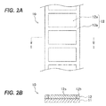
- the medium 10 includes a label liner (or backing sheet) 11 and a label member (or label sheet) 12 removably or temporarily attached to the label liner 11.
- the label member 12 has one or more label portions (or labels) 12a and a waste portion (or continuous waste portion) 12b that is a non-label portion.
- the medium 10 is cut (or half-cut) so that the label member 12 is cut into the label portions 12a and waste portion 12b without cutting the label liner 11.
- the printer 50 prints on the label portions 12a of the medium 10.
- the label winding device 100 receives the medium 10 discharged from the printer 50, separates the waste portion 12b from the label liner 11 of the medium 10 to collect the waste portion 12b, and winds the label portions 12a with the label liner 11.
- the printer 50 is an image forming apparatus that includes a print engine, such as an electrophotographic print engine or an inkjet print engine, and other components, and prints arbitrary information on the label portions 12a of the medium 10 supplied from a medium feeder (or paper roll feeder) 51.
- a roll of the medium 10 (e.g., a paper roll) is set on the medium feeder 51, and is continuously fed into the printer 50 by rotation of the medium feeder 51 in the direction indicated by arrow A in FIG. 1 .
- the medium 10 includes the label liner 11 and the label member 12 removably attached to a surface of the label liner 11.
- the label member 12 may be cut before being set on the medium feeder 51, or may be cut in the printer 50.
- the label winding device 100 receives the medium 10 discharged from the printer 50, separates the waste portion 12b, which is the non-label portion, from the label liner 11 of the medium 10 to collect the waste portion 12b, and winds the label portions 12a together with the label liner 11.
- the label winding device 100 includes a tension bar 101 as a label separator, a tension bar movement limiting frame 102, one or more tension bar position sensors 103, an idle roller 104, a peeling bar 105 as a waste guide, a label winder 106, a waste winder 107, a start switch 108, a stop switch 109, and an alarm lamp 110 as an alarm.
- the label winding device 100 may further include an operation unit 24 for receiving input from an operator, and an interface 25 for communicating with an external device.
- the tension bar 101 produces sag in the medium 10 between the printer 50 and the label winder 106, and generates the winding timing.
- the tension bar 101 is slidable in the tension bar movement limiting frame 102 in the vertical direction in FIG. 1 , and absorbs difference in medium conveying speed between the printer 50 and the label winder 106.
- the tension bar position sensors 103 detect the position of the tension bar 101 in the vertical direction.
- a controller 20 drives a label winding motor 22 (described later) to rotate the label winder 106.
- the controller 20 stops the label winding motor 22.
- the idle roller 104 is disposed downstream of the tension bar 101 in a medium conveying direction, and forms a label winding angle.
- the peeling bar 105 is disposed away from the idle roller 104, guides the waste portion 12b to the waste winder 107.
- the peeling bar 105 forms a waste separation angle for separating the waste portion 12b, the waste separation angle depending on the positional relationship between the peeling bar 105 and the idle roller 104.
- the peeling bar 105 forms the waste separation angle at a waste separation portion at which the waste portion 12b is separated from the label liner 11. Specifically, the peeling bar 105 separates the medium 10 into the waste portion 12b to be wound around the waste winder 107 and the label portions 12a to be wound around the label winder 106.
- the label winder 106 is rotated by driving force transmitted from the label winding motor 22 in either of the directions indicated by arrows C and D in FIG. 1 , and winds the label portions 12a together with the label liner 11 of the medium 10 discharged from the printer 50.
- the label winder 106 winds the label portions 12a with the label liner 11 to form a label roll.
- the label winder 106 is configured so that its rotational direction can be switched between the directions of arrows C and D depending on whether the label portions 12a (or label liner 11) are wound inward (in a face-in manner) or outward (in a face-out manner).
- the waste winder 107 is rotated by driving force transmitted from a waste winding motor 23 (described later) in the direction indicated by arrow B in FIG. 1 and winds the waste portion 12b, which is the non-label portion, of the medium 10 discharged from the printer 50.
- the waste winder 107 winds the waste portion 12b to form a waste roll.
- the start switch 108 is a switch for starting the label winder 106 and waste winder 107. In this embodiment, they are started if the start switch 108 is pressed down and the tension bar 101 is at the lowermost position in the tension bar movement limiting frame 102.
- the stop switch 109 is a switch for stopping the label winder 106 and waste winder 107. In this embodiment, if the stop switch 109 is pressed down, the label winder 106 and waste winder 107 stops.
- the alarm lamp 110 alerts an operator if a waste break detector (described later) detects break of the waste portion 12b.
- the alarm lamp 110 is a light emitting diode (LED) lamp that lights up if the waste break detector detects break of the waste portion 12b.
- the alarm is not limited to the LED lamp, and may be an alarm using sound, such as a beep sound, an alarm that displays a message indicating occurrence of waste break on a display (not illustrated), or other alarm means.
- FIG. 3 is a block diagram illustrating a functional configuration of the label winding device 100 according to this embodiment.
- the label winding device 100 includes a storage unit (or memory) 21, the label winding motor 22, the waste winding motor 23, the tension bar position sensors 103, and a slit sensor 121 as a sensor, which are connected to the controller 20 as the waste break detector.
- the storage unit 21 includes a storage device, such as a random access memory (RAM), a hard disk drive (HDD), a flash memory, and a read only memory (ROM).
- a storage device such as a random access memory (RAM), a hard disk drive (HDD), a flash memory, and a read only memory (ROM).
- the storage unit 21 temporarily stores sensor input values from the slit sensor 121 (described later) or the like, and stores a control program executed by the controller 20 and other information.
- the label winding motor 22 is a driving motor that operates in accordance with instructions from the controller 20 and rotates the label winder 106.
- the waste winding motor 23 is a driving motor that operates in accordance with instructions from the controller 20 and rotates the waste winder 107.
- the one or more tension bar position sensors 103 are disposed along the tension bar movement limiting frame 102 illustrated in FIG. 1 , and output the position of the tension bar 101 in the tension bar movement limiting frame 102 to the controller 20. Based on input from the tension bar position sensors 103, the controller 20 controls start and stop of the label winding motor 22 and the like.
- the slit sensor 121 detects the rotational speed or state of the peeling bar 105.
- the slit sensor 121 is a sensor that outputs a detection signal indicating the rotational state of the peeling bar 105 to the controller 20.
- the configuration of the slit sensor 121 will be described later with reference to FIG. 4 .
- the controller 20 controls driving of the label winding motor 22, waste winding motor 23, and the like based on input signals from the tension bar position sensors 103 and slit sensor 121, thereby controlling the operation of the label winding device 100.
- the controller 20 detects break of the waste portion 12b on the basis of the detection by the slit sensor 121.
- FIG. 4 is an enlarged partial view illustrating the idle roller 104 and peeling bar 105.
- the idle roller 104 includes a roller main body 104a formed in a cylindrical shape and a roller shaft 104b that rotatably supports the roller main body 104a.
- the idle roller 104 is configured so that it can rotate clockwise or counterclockwise in accordance with movement of the medium 10 due to tension applied to the medium 10 by rotation of the label winder 106 or waste winder 107.
- the peeling bar 105 is disposed immediately above the idle roller 104 and guides the waste portion 12b from the medium 10 to the waste winder 107, as described above.
- the peeling bar 105 includes a bar main body 105a and a support 105b that rotatably supports the bar main body 105a.
- the peeling bar 105 is connected to a slit plate 120 so that the slit plate 120 rotates with the peeling bar 105.
- the support 105b is connected to the slit plate 120.
- the slit plate 120 has a disk portion 120a (or a circular portion) having one or more opening portions 120b and one or more non-opening portions (or light blocking portions) 120c.
- the opening portions 120b are formed at predetermined intervals along a circumferential direction of the disk portion 120a.
- the non-opening portions 120c are formed between each adjacent pair of the opening portions 120b.
- the slit sensor 121 detects one of the opening portions 120b and non-opening portions 120c depending on the rotational position of the slit plate 120 and outputs a detection value corresponding to the detected portion to the controller 20.
- the slit sensor 121 serving as a sensor, is disposed across the slit plate 120.
- the slit sensor 121 detects transmission or non-transmission of light at the opening portions 120b or non-opening portions 120c.
- the slit sensor 121 detects transmission of light at one of the opening portions 120b of the slit plate 120, it outputs a value "1" as a detection result to the controller 20; if the slit sensor 121 detects non-transmission of light at one of the non-opening portions 120c of the slit plate 120, it outputs a value "0" as a detection result to the controller 20. If the waste portion 12b is normally wound, the peeling bar 105 continues to rotate, so the slit sensor 121 outputs detection values "1" and "0" repeatedly.
- the peeling bar 105 and the slit plate 120 connected to the support 105b stop, so the slit sensor 121 constantly outputs a detection value of either "1" or "0".
- the controller 20 detects that the waste portion 12b has broken if the detection value output from the slit sensor 121 is constant for a predetermined period of time.
- the controller 20, functioning as the waste break detector detects occurrence of waste break by monitoring the value output from the slit sensor 121 for a predetermined period of time.
- the medium 10 is set on the medium feeder 51 illustrated in FIG. 1 , and the printer 100 starts to print on the label portions 12a of the medium 10 (START).
- the controller 20 illustrated in FIG. 3 determines whether a start condition is satisfied (step S40). The start condition is satisfied if the start switch 108 of the label winding device 100 illustrated in FIG. 1 is pressed down and the tension bar 101 is at the lowermost position in the tension bar movement limiting frame 102. If the start condition is not satisfied (NO in step S40), the controller 20 waits until the start condition is satisfied. If the start condition is satisfied (YES in step S40), the controller 20 drives the label winding motor 22 to rotate the label winder 106 and drives the waste winding motor 23 to rotate the waste winder 107, thereby starting winding of the label portions 12a and waste portion 12b (step S41). At this time, the controller 20 resets and starts first and second timers, which are included in, for example, the controller 20.
- step S42 determines whether a stop condition is satisfied.
- the stop condition is satisfied if the stop switch 109 of the label winding device 100 illustrated in FIG. 1 is pressed down or if the tension bar 101 is at the uppermost position in the tension bar movement limiting frame 102. If the stop condition is satisfied (YES in step S42), the controller 20 stops the label winding motor 22 and waste winding motor 23 (step S48), thereby stopping winding of the label portions 12a and waste portion 12b, and ending the process (END).
- step S43 determines whether the first timer has measured a first period of time (i.e., a first period of time has elapsed) (step S43). If the first timer has not measured the first period of time (NO in step S43), the process of the controller 20 returns to step S42. If the first timer has measured the first period of time (YES in step S43), the controller 20 stores the detection value ("1" or "0") of the slit sensor 121 in the storage unit 21 (step S44).
- the controller 20 determines whether the second timer has measured a second period of time (i.e., a second period of time has elapsed) (step S45). If the second timer has not measured the second period of time (NO in step S45), the controller 20 resets and starts the first timer, and returns to step S42. If the second timer has measured the second period of time (YES in step S45), the controller 20 determines whether the detection values stored in the storage unit 21 within the second period of time after the start of the second timer are the same (step S46). If the detection values are not the same (NO in step S46), the controller 20 resets and starts the first and second timers, and returns to step S42.
- a second period of time i.e., a second period of time has elapsed
- the controller 20 detects stoppage of rotation of the peeling bar 105 illustrated in FIGs. 1 and 4 , that is, occurrence of waste break, and turns on the alarm lamp 110 illustrated in FIG. 1 (step S47), and stops the label winding motor 22 and the waste winding motor 23 (step S48), thereby stopping winding of the label portions 12a and waste portion 12b, and ending the process (END).
- the first period of time is 5 ms and the second period of time is 10 s.
- the first and second periods of time may be changed or determined appropriately depending on the waste winding speed or the like.
- the label winding device includes the sensor for detecting the rotational state or speed of the waste guide and the waste break detector for detecting break of the waste portion on the basis of the detection by the sensor. This eliminates the need for an operator to monitor the label winding device to detect occurrence of waste break, improving user-friendliness. Further, according to this embodiment, it is possible to detect occurrence of waste break and facilitate reset from the waste break position.
- the first embodiment has the slit plate provided to the peeling bar for separating the waste portion, detects occurrence of break of the waste portion on the bases of detection of rotation of the slit plate, and stops the waste winding operation. This eliminates the need for an operator to monitor the device, and facilitates reset from the waste break position.
- the conventional technique requires that the waste portion is formed continuously at a given position in the surface sheet. This limits the shape of the waste portion and therefore also limits the shapes of the label portions, so that labels having desired shapes cannot be manufactured. Further, the conventional technique requires the additional mechanism for reinforcing the waste portion, which complicates or enlarges the apparatus, and requires the reinforcing members in addition to the long sheet, resulting in high manufacturing cost.
- the first embodiment can solve the problems regarding the process of separating the waste portion from the label member and improve waste winding efficiency.
- the label portions 12a and waste portion 12b can be wound while the waste portion 12b is constantly in contact with the peeling bar 105.
- the tension by the label winder 106 is greater than the tension by the waste winder 107, the waste portion 12b may be pulled toward the label winder 106, become slack, and separate from the peeling bar 105, as illustrated in FIG. 6 .
- the peeling bar 105 stops, so that even though no waste break occurs, occurrence of waste break may be erroneously detected.
- the second embodiment can prevent such erroneous detection and correctly detect occurrence of waste break.
- FIG. 7 is a view illustrating a configuration of a label winding device 200 according to this embodiment.
- the label winding device 200 includes a peeling bar 130 in place of the peeling bar 105 described in the first embodiment.
- the label winding device 200 also includes a peeling bar movement limiting frame 131 as a waste guide installation portion in which the peeling bar 130 is slidably disposed, and a tension applying member 132 as an urging member.
- the peeling bar 130 is disposed in the peeling bar movement limiting frame 131 so that it can slide in accordance with change in tension applied to the medium 10 by the waste winder 107 and change in tension applied to the medium 10 by the label winder 106.
- the peeling bar movement limiting frame 131 limits the range of movement of the peeling bar 130
- the peeling bar movement limiting frame 131 is horizontally disposed.
- the peeling bar 130 is slidable in the peeling bar movement limiting frame 131 in the left-right direction (horizontal direction) in FIG. 7 .
- the tension applying member 132 urges the peeling bar 130 in the peeling bar movement limiting frame 131 in a predetermined direction (here, toward the position X in FIG. 7 ).
- the peeling bar 130 abuts the waste portion 12b at the position X in FIG. 7 ; when the tension by the waste winder 107 is greater than the tension by the label winder 106, the peeling bar 130 abuts the waste portion 12b at the position Y in FIG. 7 .
- the peeling bar 130 slides in the peeling bar movement limiting frame 131 in the left-right direction in FIG. 7 while constantly abutting the waste portion 12b. This can prevent occurrence of slack in the waste portion 12b.
- the peeling bar movement limiting frame 131 extends across a common tangent line 150 touching both the label roll and the waste roll when the diameter of the label roll is maximum and the diameter of the waste roll is minimum.
- the peeling bar movement limiting frame 131 is configured so that the peeling bar 130 can slide across the common tangent line 150.
- the peeling bar movement limiting frame 131 is configured so that the peeling bar 130 can slide toward the position X1 across the tangent line 150 while completely passing through the tangent line 150. Because of variation in adhesion, there is a case where the waste portion 12b is difficult to separate from the medium 10. In this case, as illustrated in FIG.
- the point at which the waste portion 12b is separated from the medium 10 may shift toward the label winder 106.
- the point at which the waste portion 12b is separated from the medium 10 shifts toward the label winder 106 at a maximum when the label winder 106 rotates in the direction of arrow C in FIG. 8C , the diameter of the label roll is maximum, and the diameter of the waste roll is minimum, and the waste portion 12b is wound by the label winder 106 without separating from the medium 10.
- the peeling bar 130 can slide completely beyond the tangent line 150 toward the position X1 in FIG. 8A , the peeling bar 130 can always abut the waste portion 12b in all possible conveying paths of the waste portion 12b.
- the operation of the label winding device 200 can be the same as in the first embodiment, and description thereof will be omitted here.
- the peeling bar 130 When the peeling bar 130 is slidable in the peeling bar movement limiting frame 131, it is preferable to perform torque control of the waste winding motor 23 in accordance with the position of the peeling bar 130. This makes it possible to control the peeling bar 130 to be constantly near the center of the peeling bar movement limiting frame 131.
- FIG. 9 is a view illustrating a configuration of a label winding device 300 according to a third embodiment.
- FIG. 10 is a block diagram illustrating a functional configuration of the label winding device 300.
- the label winding device 300 controls the torque of the waste winding motor 23 in accordance with the position of the peeling bar 130.
- the label winding device 300 includes one or more peeling bar position sensors 133 as waste guide position sensors for detecting the sliding position of the peeling bar 130 in the peeling bar movement limiting frame 131.
- the peeling bar position sensors 133 are disposed along the peeling bar movement limiting frame 131 as the waste guide installation portion.
- the peeling bar position sensors 133 output the position of the peeling bar 130 in the peeling bar movement limiting frame 131 to the controller 20.
- the controller 20 controls either or both of the winding torque of the waste winder 107 and the winding torque of the label winder 106 in accordance with the sliding position detected by the peeling bar position sensors 133.
- the waste winding motor 23 in FIG. 10 is a motor whose rotating torque can be controlled. Based on input signals from the peeling bar position sensors 133, label material information input via the operation unit 24, or the like, the controller 20 feedback-controls the rotating torque of the waste winding motor 23 so that the peeling bar 130 is constantly near the center of the peeling bar movement limiting frame 131.
- the printer 50 starts printing on the label portions 12a of the medium 10, and the label winder 106 and waste winder 107 start to rotate. At this time, the controller 20 starts the waste winding motor 23 at a predetermined torque.
- the peeling bar 130 is pulled by the tension applying member 132 toward the position X1 in FIG. 11A .
- the controller 20 monitors the input signals from the peeling bar position sensors 133 and, if the peeling bar 130 is still on the position X1 side of the center of the peeling bar movement limiting frame 131 after a predetermined period of time has elapsed, the controller 20 increases the torque of the waste winding motor 23 in stages. This increases the waste winding speed of the waste winder 107, and the peeling bar 130 begins to move toward the position Y1 in FIG. 11A .
- the controller 20 decreases the torque of the waste winding motor 23. This decreases the waste winding speed of the waste winder 107, and the peeling bar 130 begins to slide toward the position X1.
- the controller 20 repeats this torque adjustment operation, and performs feedback control so that the peeling bar 130 is constantly near the center of the peeling bar movement limiting frame 131.
- the third embodiment it is possible to prevent waste break without reinforcing the waste portion as in the conventional technique.
- the label winding device 300 is configured so that it can detect information indicating the position in the horizontal direction of the peeling bar, which can constantly abut the waste portion, and control the torque of the waste winding motor in accordance with the position information of the peeling bar. This makes it possible to prevent slack in the waste portion, thereby preventing twist of the waste portion occurring due to the slack and concentration of the waste winding torque on a part of the waste portion due to the twist. Further, the torque of the waste winding motor can be feedback-controlled according to the position of the peeling bar. This makes it possible to constantly wind the waste portion at the optimum torque and prevent occurrence of waste break.
- the third embodiment adjusts the waste winding torque by feedback control.
- the medium label paper
- the label winding device 300 may receive information indicating the length of the medium per page via the interface 25 from an upstream device, such as the printer, knowing the length and apply a result of the torque adjustment in the first page to the torque adjustment in pages following the first page.
- the label winding device 300 may determine the length of the medium per page by detecting periodical variation in the torque, and in pages after the determination, predict torque variation and adjust the waste winding torque by feedback control using the predicted torque variation.
- the label winding device 400 according to the fourth embodiment differs from the label winding device 200 of the second embodiment in the direction in which the peeling bar slides and the position at which the tension applying member is disposed.
- the label winding device 400 will be described below.
- FIG. 12 is a view illustrating a configuration of the label winding device 400 according to this embodiment.
- the label winding device 400 includes a peeling bar 140, a peeling bar movement limiting frame 141, and a tension applying member 142.
- the peeling bar movement limiting frame 141 is disposed so that an angle at which the waste portion 12b is guided to the waste winder 107 by the peeling bar 140 is substantially independent of the sliding position of the peeling bar 140.
- the peeling bar movement limiting frame 141 is formed so that a winding angle of the waste portion 12b with respect to the peeling bar 140, i.e., a guide angle with respect to the waste winder 107, is substantially constant.
- the tension applying member 142 is disposed to urge the peeling bar 140 toward the position Z in FIG. 12 .
- the peeling bar 140 abuts the waste portion 12b at the position Z in FIG. 12 ; when the tension by the waste winder 107 is greater than the tension by the label winder 106, the peeling bar 140 abuts the waste portion 12b at the position W in FIG. 12 .
- the operation of the label winding device 400 can be the same as in the second embodiment, so descriptions thereof will be omitted.
- the peeling bar movement limiting frame is disposed so that the waste winding angle with respect to the peeling bar is substantially constant. This makes it possible to reduce the load on the waste portion as compared to the label winding device 200 according to the second embodiment.
- the label winding device 400 in the fourth embodiment may detect the position information of the peeling bar 140 and control the torque of the waste winding motor 23 in accordance with the position information of the peeling bar 140, as in the third embodiment.
- the above embodiments can provide a label winding device that can solve problems regarding the process of separating the waste portion from the label member and improve waste winding efficiency and a printing system including the label winding device.
Abstract
Description
- The present invention relates to a label winding device and a printing system, and more particularly, to a label winding device including a waste winder for removing a continuous waste portion after label processing, such as label printing.
-
Japanese Patent Application Publication No. 2008-44171 - However, despite the reinforcement, break of the continuous waste portion may occur. To promptly respond to the waste break, an operator needs to monitor the apparatus.
- An aspect of the present invention is intended to provide a label winding device capable of improving user-friendliness, and a printing system including the label winding device.
- According to an aspect of the present invention, there is provided a label winding device for receiving a medium including a label liner and a label member that is removably attached to the label liner and has at least one label portion and a waste portion, separating the waste portion from the label liner at a waste separation portion, and winding the at least one label portion with the label liner, the label winding device including: a waste winder for winding the separated waste portion; a label winder for winding the at least one label portion with the label liner without the separated waste portion; a waste guide for guiding the separated waste portion to the waste winder; a support for rotatably supporting the waste guide; a sensor for detecting a rotational speed of the waste guide; and a waste break detector for detecting break of the waste portion on a basis of the detection by the sensor.
- According to another aspect of the present invention, there is provided a label winding device for receiving a medium including a label liner and a label member that is removably attached to the label liner and has at least one label portion and a waste portion, separating the waste portion from the label liner at a waste separation portion, and winding the at least one label portion with the label liner, the label winding device including: a waste winder for winding the separated waste portion; a label winder for winding the at least one label portion with the label liner without the separated waste portion; a waste guide for guiding the separated waste portion to the waste winder; a waste guide installation portion in which the waste guide is slidably disposed; a waste guide position sensor for detecting a position of the waste guide; and a controller for controlling a winding torque of the waste winder and a winding torque of the label winder in accordance with the position detected by the waste guide position sensor.
- According to another aspect of the present invention, there is provided a printing system including: one of the above label winding devices; and an image forming apparatus for forming information on the at least one label portion of the label member.
- In the attached drawings:
-
FIG. 1 is an overall view illustrating a configuration of a printing system including a label winding device according to a first embodiment; -
FIG. 2A is a top view of a medium; -
FIG. 2B is a sectional view taken along line I-I ofFIG. 2A ; -
FIG. 3 is a block diagram illustrating a functional configuration of the label winding device according to the first embodiment; -
FIG. 4 is an enlarged partial view illustrating an idle roller and a peeling bar; -
FIG. 5 is a flowchart illustrating the operation of the label winding device according to the first embodiment; -
FIG. 6 is a schematic view for explaining occurrence of slack in a waste portion; -
FIG. 7 is a view illustrating a configuration of a label winding device according to a second embodiment; -
FIGs. 8A to 8C are schematic views for explaining a configuration of a peeling bar movement limiting frame; -
FIG. 9 is a view illustrating a configuration of a label winding device according to a third embodiment; -
FIG. 10 is a block diagram illustrating a functional configuration of the label winding device according to the third embodiment; -
FIGs. 11A and 11B are schematic views for explaining adjustment of a waste winding torque by feedback control; -
FIG. 12 is a view illustrating a configuration of a label winding device according to a fourth embodiment. - Embodiments of the present invention will now be described with reference to the attached drawings. The present invention is not limited to the following embodiments and may be practiced in various other aspects without departing from the scope of the invention.
-
FIG. 1 is an overall view illustrating a configuration of aprinting system 1 including alabel winding device 100 according to a first embodiment. Theprinting system 1 includes aprinter 50 and thelabel winding device 100. Theprinter 50 prints on a medium (or web) 10. As illustrated inFIGs. 2A and 2B , themedium 10 includes a label liner (or backing sheet) 11 and a label member (or label sheet) 12 removably or temporarily attached to thelabel liner 11. Thelabel member 12 has one or more label portions (or labels) 12a and a waste portion (or continuous waste portion) 12b that is a non-label portion. For example, themedium 10 is cut (or half-cut) so that thelabel member 12 is cut into thelabel portions 12a andwaste portion 12b without cutting thelabel liner 11. Theprinter 50 prints on thelabel portions 12a of themedium 10. Thelabel winding device 100 receives themedium 10 discharged from theprinter 50, separates thewaste portion 12b from thelabel liner 11 of themedium 10 to collect thewaste portion 12b, and winds thelabel portions 12a with thelabel liner 11. - The
printer 50 is an image forming apparatus that includes a print engine, such as an electrophotographic print engine or an inkjet print engine, and other components, and prints arbitrary information on thelabel portions 12a of themedium 10 supplied from a medium feeder (or paper roll feeder) 51. A roll of the medium 10 (e.g., a paper roll) is set on themedium feeder 51, and is continuously fed into theprinter 50 by rotation of themedium feeder 51 in the direction indicated by arrow A inFIG. 1 . As described above, themedium 10 includes thelabel liner 11 and thelabel member 12 removably attached to a surface of thelabel liner 11. Thelabel member 12 may be cut before being set on themedium feeder 51, or may be cut in theprinter 50. - The
label winding device 100 receives themedium 10 discharged from theprinter 50, separates thewaste portion 12b, which is the non-label portion, from thelabel liner 11 of themedium 10 to collect thewaste portion 12b, and winds thelabel portions 12a together with thelabel liner 11. Thelabel winding device 100 includes atension bar 101 as a label separator, a tension barmovement limiting frame 102, one or more tensionbar position sensors 103, anidle roller 104, apeeling bar 105 as a waste guide, alabel winder 106, awaste winder 107, astart switch 108, astop switch 109, and analarm lamp 110 as an alarm. Thelabel winding device 100 may further include anoperation unit 24 for receiving input from an operator, and aninterface 25 for communicating with an external device. - The
tension bar 101 produces sag in themedium 10 between theprinter 50 and thelabel winder 106, and generates the winding timing. Thetension bar 101 is slidable in the tension barmovement limiting frame 102 in the vertical direction inFIG. 1 , and absorbs difference in medium conveying speed between theprinter 50 and thelabel winder 106. The tensionbar position sensors 103 detect the position of thetension bar 101 in the vertical direction. - In this embodiment, if the tension
bar position sensors 103 detect that thetension bar 101 is at the lowermost position in the tension barmovement limiting frame 102, a controller 20 (described later) drives a label winding motor 22 (described later) to rotate thelabel winder 106. On the other hand, if the tensionbar position sensors 103 detect that thetension bar 101 is at the uppermost position in the tension barmovement limiting frame 102, thecontroller 20 stops thelabel winding motor 22. - The
idle roller 104 is disposed downstream of thetension bar 101 in a medium conveying direction, and forms a label winding angle. - The
peeling bar 105 is disposed away from theidle roller 104, guides thewaste portion 12b to thewaste winder 107. The peelingbar 105 forms a waste separation angle for separating thewaste portion 12b, the waste separation angle depending on the positional relationship between the peelingbar 105 and theidle roller 104. The peelingbar 105 forms the waste separation angle at a waste separation portion at which thewaste portion 12b is separated from thelabel liner 11. Specifically, the peelingbar 105 separates the medium 10 into thewaste portion 12b to be wound around thewaste winder 107 and thelabel portions 12a to be wound around thelabel winder 106. - The
label winder 106 is rotated by driving force transmitted from thelabel winding motor 22 in either of the directions indicated by arrows C and D inFIG. 1 , and winds thelabel portions 12a together with thelabel liner 11 of the medium 10 discharged from theprinter 50. Thelabel winder 106 winds thelabel portions 12a with thelabel liner 11 to form a label roll. Thelabel winder 106 is configured so that its rotational direction can be switched between the directions of arrows C and D depending on whether thelabel portions 12a (or label liner 11) are wound inward (in a face-in manner) or outward (in a face-out manner). - The
waste winder 107 is rotated by driving force transmitted from a waste winding motor 23 (described later) in the direction indicated by arrow B inFIG. 1 and winds thewaste portion 12b, which is the non-label portion, of the medium 10 discharged from theprinter 50. Thewaste winder 107 winds thewaste portion 12b to form a waste roll. - The
start switch 108 is a switch for starting thelabel winder 106 andwaste winder 107. In this embodiment, they are started if thestart switch 108 is pressed down and thetension bar 101 is at the lowermost position in the tension barmovement limiting frame 102. - The
stop switch 109 is a switch for stopping thelabel winder 106 andwaste winder 107. In this embodiment, if thestop switch 109 is pressed down, thelabel winder 106 andwaste winder 107 stops. - The
alarm lamp 110 alerts an operator if a waste break detector (described later) detects break of thewaste portion 12b. Specifically, thealarm lamp 110 is a light emitting diode (LED) lamp that lights up if the waste break detector detects break of thewaste portion 12b. The alarm is not limited to the LED lamp, and may be an alarm using sound, such as a beep sound, an alarm that displays a message indicating occurrence of waste break on a display (not illustrated), or other alarm means. -
FIG. 3 is a block diagram illustrating a functional configuration of thelabel winding device 100 according to this embodiment. Thelabel winding device 100 includes a storage unit (or memory) 21, thelabel winding motor 22, thewaste winding motor 23, the tensionbar position sensors 103, and aslit sensor 121 as a sensor, which are connected to thecontroller 20 as the waste break detector. - The
storage unit 21 includes a storage device, such as a random access memory (RAM), a hard disk drive (HDD), a flash memory, and a read only memory (ROM). For example, thestorage unit 21 temporarily stores sensor input values from the slit sensor 121 (described later) or the like, and stores a control program executed by thecontroller 20 and other information. - The
label winding motor 22 is a driving motor that operates in accordance with instructions from thecontroller 20 and rotates thelabel winder 106. - The
waste winding motor 23 is a driving motor that operates in accordance with instructions from thecontroller 20 and rotates thewaste winder 107. - The one or more tension
bar position sensors 103 are disposed along the tension barmovement limiting frame 102 illustrated inFIG. 1 , and output the position of thetension bar 101 in the tension barmovement limiting frame 102 to thecontroller 20. Based on input from the tensionbar position sensors 103, thecontroller 20 controls start and stop of thelabel winding motor 22 and the like. - The
slit sensor 121 detects the rotational speed or state of the peelingbar 105. Theslit sensor 121 is a sensor that outputs a detection signal indicating the rotational state of the peelingbar 105 to thecontroller 20. The configuration of theslit sensor 121 will be described later with reference toFIG. 4 . - The
controller 20 controls driving of thelabel winding motor 22,waste winding motor 23, and the like based on input signals from the tensionbar position sensors 103 and slitsensor 121, thereby controlling the operation of thelabel winding device 100. Thecontroller 20 detects break of thewaste portion 12b on the basis of the detection by theslit sensor 121. - Next, the configuration of the
idle roller 104 and peelingbar 105 in this embodiment will be described with reference toFIG. 4. FIG. 4 is an enlarged partial view illustrating theidle roller 104 and peelingbar 105. - The
idle roller 104 includes a rollermain body 104a formed in a cylindrical shape and aroller shaft 104b that rotatably supports the rollermain body 104a. Theidle roller 104 is configured so that it can rotate clockwise or counterclockwise in accordance with movement of the medium 10 due to tension applied to the medium 10 by rotation of thelabel winder 106 orwaste winder 107. - The peeling
bar 105 is disposed immediately above theidle roller 104 and guides thewaste portion 12b from the medium 10 to thewaste winder 107, as described above. The peelingbar 105 includes a barmain body 105a and asupport 105b that rotatably supports the barmain body 105a. The peelingbar 105 is connected to aslit plate 120 so that theslit plate 120 rotates with the peelingbar 105. Specifically, thesupport 105b is connected to theslit plate 120. Theslit plate 120 has adisk portion 120a (or a circular portion) having one ormore opening portions 120b and one or more non-opening portions (or light blocking portions) 120c. The openingportions 120b are formed at predetermined intervals along a circumferential direction of thedisk portion 120a. Thenon-opening portions 120c are formed between each adjacent pair of the openingportions 120b. Theslit sensor 121 detects one of the openingportions 120b andnon-opening portions 120c depending on the rotational position of theslit plate 120 and outputs a detection value corresponding to the detected portion to thecontroller 20. Specifically, theslit sensor 121, serving as a sensor, is disposed across theslit plate 120. Theslit sensor 121 detects transmission or non-transmission of light at the openingportions 120b ornon-opening portions 120c. Specifically, if theslit sensor 121 detects transmission of light at one of the openingportions 120b of theslit plate 120, it outputs a value "1" as a detection result to thecontroller 20; if theslit sensor 121 detects non-transmission of light at one of thenon-opening portions 120c of theslit plate 120, it outputs a value "0" as a detection result to thecontroller 20. If thewaste portion 12b is normally wound, the peelingbar 105 continues to rotate, so theslit sensor 121 outputs detection values "1" and "0" repeatedly. However, if waste break occurs, the peelingbar 105 and theslit plate 120 connected to thesupport 105b stop, so theslit sensor 121 constantly outputs a detection value of either "1" or "0". Thecontroller 20 detects that thewaste portion 12b has broken if the detection value output from theslit sensor 121 is constant for a predetermined period of time. Thecontroller 20, functioning as the waste break detector, detects occurrence of waste break by monitoring the value output from theslit sensor 121 for a predetermined period of time. - Next, the operation of the
printing system 1 according to this embodiment having the above configuration, especially the operation of thelabel winding device 100, will be described with reference toFIGs. 1 to 4 and the flowchart ofFIG. 5 . - First, the medium 10 is set on the
medium feeder 51 illustrated inFIG. 1 , and theprinter 100 starts to print on thelabel portions 12a of the medium 10 (START). - The
controller 20 illustrated inFIG. 3 determines whether a start condition is satisfied (step S40). The start condition is satisfied if thestart switch 108 of thelabel winding device 100 illustrated inFIG. 1 is pressed down and thetension bar 101 is at the lowermost position in the tension barmovement limiting frame 102. If the start condition is not satisfied (NO in step S40), thecontroller 20 waits until the start condition is satisfied. If the start condition is satisfied (YES in step S40), thecontroller 20 drives thelabel winding motor 22 to rotate thelabel winder 106 and drives thewaste winding motor 23 to rotate thewaste winder 107, thereby starting winding of thelabel portions 12a andwaste portion 12b (step S41). At this time, thecontroller 20 resets and starts first and second timers, which are included in, for example, thecontroller 20. - Next, the
controller 20 determines whether a stop condition is satisfied (step S42). The stop condition is satisfied if thestop switch 109 of thelabel winding device 100 illustrated inFIG. 1 is pressed down or if thetension bar 101 is at the uppermost position in the tension barmovement limiting frame 102. If the stop condition is satisfied (YES in step S42), thecontroller 20 stops thelabel winding motor 22 and waste winding motor 23 (step S48), thereby stopping winding of thelabel portions 12a andwaste portion 12b, and ending the process (END). - On the other hand, if the stop condition is not satisfied (NO in step S42), the
controller 20 determines whether the first timer has measured a first period of time (i.e., a first period of time has elapsed) (step S43). If the first timer has not measured the first period of time (NO in step S43), the process of thecontroller 20 returns to step S42. If the first timer has measured the first period of time (YES in step S43), thecontroller 20 stores the detection value ("1" or "0") of theslit sensor 121 in the storage unit 21 (step S44). - The
controller 20 then determines whether the second timer has measured a second period of time (i.e., a second period of time has elapsed) (step S45). If the second timer has not measured the second period of time (NO in step S45), thecontroller 20 resets and starts the first timer, and returns to step S42. If the second timer has measured the second period of time (YES in step S45), thecontroller 20 determines whether the detection values stored in thestorage unit 21 within the second period of time after the start of the second timer are the same (step S46). If the detection values are not the same (NO in step S46), thecontroller 20 resets and starts the first and second timers, and returns to step S42. On the other hand, if the detection values are the same (YES in step S46), thecontroller 20 detects stoppage of rotation of the peelingbar 105 illustrated inFIGs. 1 and4 , that is, occurrence of waste break, and turns on thealarm lamp 110 illustrated inFIG. 1 (step S47), and stops thelabel winding motor 22 and the waste winding motor 23 (step S48), thereby stopping winding of thelabel portions 12a andwaste portion 12b, and ending the process (END). In one preferable example, the first period of time is 5 ms and the second period of time is 10 s. However, the first and second periods of time may be changed or determined appropriately depending on the waste winding speed or the like. - As above, in this embodiment, the label winding device includes the sensor for detecting the rotational state or speed of the waste guide and the waste break detector for detecting break of the waste portion on the basis of the detection by the sensor. This eliminates the need for an operator to monitor the label winding device to detect occurrence of waste break, improving user-friendliness. Further, according to this embodiment, it is possible to detect occurrence of waste break and facilitate reset from the waste break position.
- Specifically, the first embodiment has the slit plate provided to the peeling bar for separating the waste portion, detects occurrence of break of the waste portion on the bases of detection of rotation of the slit plate, and stops the waste winding operation. This eliminates the need for an operator to monitor the device, and facilitates reset from the waste break position.
- In the aforementioned conventional technique, even though the continuous waste portion is reinforced, waste break is not completely prevented. When no operator is present near the apparatus, if waste break occurs, the waste winding operation cannot be stopped promptly. Thus, the broken waste portion is wound around the winding roller together with the label portions and release sheet. This makes it difficult to find the position at which the waste portion breaks, so that it takes time to reset the waste portion to the waste winding roller.
- Further, the conventional technique requires that the waste portion is formed continuously at a given position in the surface sheet. This limits the shape of the waste portion and therefore also limits the shapes of the label portions, so that labels having desired shapes cannot be manufactured. Further, the conventional technique requires the additional mechanism for reinforcing the waste portion, which complicates or enlarges the apparatus, and requires the reinforcing members in addition to the long sheet, resulting in high manufacturing cost.
- The first embodiment can solve the problems regarding the process of separating the waste portion from the label member and improve waste winding efficiency.
- In the first embodiment, when the tension applied to the medium 10 by rotation of the
label winder 106 is equal to the tension applied to the medium 10 by rotation of thewaste winder 107, thelabel portions 12a andwaste portion 12b can be wound while thewaste portion 12b is constantly in contact with the peelingbar 105. However, for example, when the tension by thelabel winder 106 is greater than the tension by thewaste winder 107, thewaste portion 12b may be pulled toward thelabel winder 106, become slack, and separate from the peelingbar 105, as illustrated inFIG. 6 . In this case, the peelingbar 105 stops, so that even though no waste break occurs, occurrence of waste break may be erroneously detected. The second embodiment can prevent such erroneous detection and correctly detect occurrence of waste break. -
FIG. 7 is a view illustrating a configuration of alabel winding device 200 according to this embodiment. In the following description, parts that are the same as in the first embodiment have the same reference characters, and descriptions thereof will be omitted. As illustrated inFIG. 7 , thelabel winding device 200 includes a peelingbar 130 in place of the peelingbar 105 described in the first embodiment. Thelabel winding device 200 also includes a peeling barmovement limiting frame 131 as a waste guide installation portion in which the peelingbar 130 is slidably disposed, and atension applying member 132 as an urging member. The peelingbar 130 is disposed in the peeling barmovement limiting frame 131 so that it can slide in accordance with change in tension applied to the medium 10 by thewaste winder 107 and change in tension applied to the medium 10 by thelabel winder 106. The peeling barmovement limiting frame 131 limits the range of movement of the peelingbar 130 The peeling barmovement limiting frame 131 is horizontally disposed. The peelingbar 130 is slidable in the peeling barmovement limiting frame 131 in the left-right direction (horizontal direction) inFIG. 7 . Thetension applying member 132 urges the peelingbar 130 in the peeling barmovement limiting frame 131 in a predetermined direction (here, toward the position X inFIG. 7 ). - With the above configuration, for example, when the tension by the
waste winder 107 is less than the tension by thelabel winder 106, the peelingbar 130 abuts thewaste portion 12b at the position X inFIG. 7 ; when the tension by thewaste winder 107 is greater than the tension by thelabel winder 106, the peelingbar 130 abuts thewaste portion 12b at the position Y inFIG. 7 . - In this manner, the peeling
bar 130 slides in the peeling barmovement limiting frame 131 in the left-right direction inFIG. 7 while constantly abutting thewaste portion 12b. This can prevent occurrence of slack in thewaste portion 12b. - As illustrated in
FIG. 8A , the peeling barmovement limiting frame 131 extends across a commontangent line 150 touching both the label roll and the waste roll when the diameter of the label roll is maximum and the diameter of the waste roll is minimum. The peeling barmovement limiting frame 131 is configured so that the peelingbar 130 can slide across the commontangent line 150. The peeling barmovement limiting frame 131 is configured so that the peelingbar 130 can slide toward the position X1 across thetangent line 150 while completely passing through thetangent line 150. Because of variation in adhesion, there is a case where thewaste portion 12b is difficult to separate from the medium 10. In this case, as illustrated inFIG. 8B , the point at which thewaste portion 12b is separated from the medium 10 may shift toward thelabel winder 106. As illustrated inFIG. 8C , the point at which thewaste portion 12b is separated from the medium 10 shifts toward thelabel winder 106 at a maximum when thelabel winder 106 rotates in the direction of arrow C inFIG. 8C , the diameter of the label roll is maximum, and the diameter of the waste roll is minimum, and thewaste portion 12b is wound by thelabel winder 106 without separating from the medium 10. Thus, with the configuration in which the peelingbar 130 can slide completely beyond thetangent line 150 toward the position X1 inFIG. 8A , the peelingbar 130 can always abut thewaste portion 12b in all possible conveying paths of thewaste portion 12b. - The operation of the
label winding device 200 can be the same as in the first embodiment, and description thereof will be omitted here. - When the peeling
bar 130 is slidable in the peeling barmovement limiting frame 131, it is preferable to perform torque control of thewaste winding motor 23 in accordance with the position of the peelingbar 130. This makes it possible to control the peelingbar 130 to be constantly near the center of the peeling barmovement limiting frame 131. -
FIG. 9 is a view illustrating a configuration of alabel winding device 300 according to a third embodiment.FIG. 10 is a block diagram illustrating a functional configuration of thelabel winding device 300. In the following description, parts that are the same as in the second embodiment have the same reference characters, and descriptions thereof will be omitted. Thelabel winding device 300 controls the torque of thewaste winding motor 23 in accordance with the position of the peelingbar 130. For this control, in addition to the configuration of thelabel winding device 200 inFIG. 7 , thelabel winding device 300 includes one or more peelingbar position sensors 133 as waste guide position sensors for detecting the sliding position of the peelingbar 130 in the peeling barmovement limiting frame 131. The peelingbar position sensors 133 are disposed along the peeling barmovement limiting frame 131 as the waste guide installation portion. The peelingbar position sensors 133 output the position of the peelingbar 130 in the peeling barmovement limiting frame 131 to thecontroller 20. Thecontroller 20 controls either or both of the winding torque of thewaste winder 107 and the winding torque of thelabel winder 106 in accordance with the sliding position detected by the peelingbar position sensors 133. - The
waste winding motor 23 inFIG. 10 is a motor whose rotating torque can be controlled. Based on input signals from the peelingbar position sensors 133, label material information input via theoperation unit 24, or the like, thecontroller 20 feedback-controls the rotating torque of thewaste winding motor 23 so that the peelingbar 130 is constantly near the center of the peeling barmovement limiting frame 131. - Next, the operation of the
label winding device 300 will be described. Here, the operation regarding the rotating torque control of thewaste winding motor 23 in thelabel winding device 300 will be described. - The
printer 50 starts printing on thelabel portions 12a of the medium 10, and thelabel winder 106 andwaste winder 107 start to rotate. At this time, thecontroller 20 starts thewaste winding motor 23 at a predetermined torque. - At this time, the peeling
bar 130 is pulled by thetension applying member 132 toward the position X1 inFIG. 11A . After starting thewaste winding motor 23, thecontroller 20 monitors the input signals from the peelingbar position sensors 133 and, if the peelingbar 130 is still on the position X1 side of the center of the peeling barmovement limiting frame 131 after a predetermined period of time has elapsed, thecontroller 20 increases the torque of thewaste winding motor 23 in stages. This increases the waste winding speed of thewaste winder 107, and the peelingbar 130 begins to move toward the position Y1 inFIG. 11A . - If the peeling
bar 130 has slid to the position Y1 side of the center of the peeling barmovement limiting frame 131, as illustrated inFIG. 11B , thecontroller 20 decreases the torque of thewaste winding motor 23. This decreases the waste winding speed of thewaste winder 107, and the peelingbar 130 begins to slide toward the position X1. Thecontroller 20 repeats this torque adjustment operation, and performs feedback control so that the peelingbar 130 is constantly near the center of the peeling barmovement limiting frame 131. - According to the third embodiment, it is possible to prevent waste break without reinforcing the waste portion as in the conventional technique.
- Specifically, in the third embodiment, the
label winding device 300 is configured so that it can detect information indicating the position in the horizontal direction of the peeling bar, which can constantly abut the waste portion, and control the torque of the waste winding motor in accordance with the position information of the peeling bar. This makes it possible to prevent slack in the waste portion, thereby preventing twist of the waste portion occurring due to the slack and concentration of the waste winding torque on a part of the waste portion due to the twist. Further, the torque of the waste winding motor can be feedback-controlled according to the position of the peeling bar. This makes it possible to constantly wind the waste portion at the optimum torque and prevent occurrence of waste break. - The third embodiment adjusts the waste winding torque by feedback control. In general, the medium (label paper) has label portions that are serially formed and have the same shape, and variation in the waste winding torque greatly depends on the shape of the waste portion. Thus, the
label winding device 300 may receive information indicating the length of the medium per page via theinterface 25 from an upstream device, such as the printer, knowing the length and apply a result of the torque adjustment in the first page to the torque adjustment in pages following the first page. Alternatively, thelabel winding device 300 may determine the length of the medium per page by detecting periodical variation in the torque, and in pages after the determination, predict torque variation and adjust the waste winding torque by feedback control using the predicted torque variation. - The
label winding device 400 according to the fourth embodiment differs from thelabel winding device 200 of the second embodiment in the direction in which the peeling bar slides and the position at which the tension applying member is disposed. Thelabel winding device 400 will be described below. -
FIG. 12 is a view illustrating a configuration of thelabel winding device 400 according to this embodiment. In the description of this embodiment, parts that are the same as those described above have the same reference characters, and descriptions thereof will be omitted. As illustrated inFIG. 12 , thelabel winding device 400 includes a peelingbar 140, a peeling barmovement limiting frame 141, and atension applying member 142. The peeling barmovement limiting frame 141 is disposed so that an angle at which thewaste portion 12b is guided to thewaste winder 107 by the peelingbar 140 is substantially independent of the sliding position of the peelingbar 140. The peeling barmovement limiting frame 141 is formed so that a winding angle of thewaste portion 12b with respect to the peelingbar 140, i.e., a guide angle with respect to thewaste winder 107, is substantially constant. Thetension applying member 142 is disposed to urge the peelingbar 140 toward the position Z inFIG. 12 . - With the above configuration, for example, when the tension by the
waste winder 107 is less than the tension by thelabel winder 106, the peelingbar 140 abuts thewaste portion 12b at the position Z inFIG. 12 ; when the tension by thewaste winder 107 is greater than the tension by thelabel winder 106, the peelingbar 140 abuts thewaste portion 12b at the position W inFIG. 12 . - The operation of the
label winding device 400 can be the same as in the second embodiment, so descriptions thereof will be omitted. - As above, in the fourth embodiment, the peeling bar movement limiting frame is disposed so that the waste winding angle with respect to the peeling bar is substantially constant. This makes it possible to reduce the load on the waste portion as compared to the
label winding device 200 according to the second embodiment. - The
label winding device 400 in the fourth embodiment may detect the position information of the peelingbar 140 and control the torque of thewaste winding motor 23 in accordance with the position information of the peelingbar 140, as in the third embodiment. - As above, the above embodiments can provide a label winding device that can solve problems regarding the process of separating the waste portion from the label member and improve waste winding efficiency and a printing system including the label winding device.
Claims (14)
- A label winding device (100, 200, 300, 400) for receiving a medium (10) including a label liner (11) and a label member (12) that is removably attached to the label liner (11) and has at least one label portion (12a) and a waste portion (12b), separating the waste portion (12b) from the label liner (11) at a waste separation portion, and winding the at least one label portion (12a) with the label liner (11), the label winding device (100, 200, 300, 400) comprising:a waste winder (107) for winding the separated waste portion (12b);a label winder (106) for winding the at least one label portion (12a) with the label liner (11) without the separated waste portion (12b);a rotatable waste guide (105, 130, 140) for guiding the separated waste portion (12b) to the waste winder (107);a sensor (121) for detecting a rotational speed of the waste guide (105, 130, 140); anda waste break detector (20) for detecting break of the waste portion (12b) on a basis of the detection by the sensor (121).
- The label winding device (100, 200, 300, 400) of claim 1, wherein the waste guide (105, 130, 140) forms a waste separation angle at the waste separation portion.
- The label winding device (100, 200, 300, 400) of claim 1 or 2, further comprising a circular slit plate (120) connected to the waste guide (105, 130, 140) so as to rotate with the waste guide (105, 130, 140), the slit plate (120) including a circular portion having an opening portion (120b) and an non-opening portion (120a),
wherein the sensor (121) is configured to detect one of the opening portion (120b) and the non-opening portion (120a) depending on a rotational position of the slit plate (120) and output a detection value corresponding to the detected portion to the waste break detector (20). - The label winding device (100, 200, 300, 400) of claim 3, wherein the waste break detector (20) is configured to detect that the waste portion (12b) has broken if the detection value output from the sensor (121) is constant for a predetermined period of time.
- The label winding device (100, 200, 300, 400) of any one of claims 1 to 4, further comprising an alarm (110) for alerting an operator if the waste break detector (20) detects break of the waste portion (12b).
- The label winding device (200, 300, 400) of any one of claims 1 to 5, further comprising a waste guide installation portion (131, 141) in which the waste guide (130, 140) is disposed so that the waste guide (130, 140) can slide in accordance with change in tension applied to the medium (10) by the waste winder (107) and change in tension applied to the medium (10) by the label winder (106).
- The label winding device (200, 300, 400) of claim 6, wherein the waste guide installation portion (131, 141) has a movement limiting frame (131, 141) for limiting a range of movement of the waste guide (130, 140).
- The label winding device (200, 300) of claim 7, wherein the movement limiting frame (131) is horizontally disposed.
- The label winding device (200, 300) of claim 8, wherein:the waste winder (107) is configured to wind the waste portion (12b) to form a waste roll;the label winder (106) is configured to wind the at least one label portion (12a) with the label liner (11) to form a label roll; andthe movement limiting frame (131) extends across a common tangent line (150) touching both the waste roll and the label roll when a diameter of the label roll is maximum and a diameter of the waste roll is minimum.
- The label winding device (400) of claim 7, wherein the movement limiting frame (141) is disposed so that an angle at which the waste portion (12b) is guided to the waste winder (107) by the waste guide (140) is substantially independent of a sliding position of the waste guide (140).
- The label winding device (200, 300, 400) of any one of claims 7 to 10, further comprising an urging member (132, 142) for urging the waste guide (130, 140) in the movement limiting frame (131, 141) in a predetermined direction.
- The label winding device (300) of any one of claims 7 to 11, further comprising:a waste guide position sensor (133) for detecting a sliding position of the waste guide (130) in the movement limiting frame (131); anda controller (20) for controlling a winding torque of the waste winder (107) in accordance with the sliding position detected by the waste guide position sensor (133).
- A label winding device (300) for receiving a medium (10) including a label liner (11) and a label member (12) that is removably attached to the label liner (11) and has at least one label portion (12a) and a waste portion (12b), separating the waste portion (12b) from the label liner (11) at a waste separation portion, and winding the at least one label portion (12a) with the label liner (11), the label winding device (300) comprising:a waste winder (107) for winding the separated waste portion (12b);a label winder (106) for winding the at least one label portion (12a) with the label liner (11) without the separated waste portion (12b);a waste guide (130) for guiding the separated waste portion (12b) to the waste winder (107);a waste guide installation portion (131) in which the waste guide (130) is slidably disposed;a waste guide position sensor (133) for detecting a position of the waste guide (130); anda controller (20) for controlling a winding torque of the waste winder (107) and a winding torque of the label winder (106) in accordance with the position detected by the waste guide position sensor (133).
- A printing system (1) comprising:the label winding device (100), 200, 300, 400) of any one of claims 1 to 13; anda printer (50) for printing information on the at least one label portion (12a) of the label member (12).
Applications Claiming Priority (1)
| Application Number | Priority Date | Filing Date | Title |
|---|---|---|---|
| JP2015091083A JP6608163B2 (en) | 2015-04-28 | 2015-04-28 | Label winding device and printing system |
Publications (2)
| Publication Number | Publication Date |
|---|---|
| EP3088316A1 true EP3088316A1 (en) | 2016-11-02 |
| EP3088316B1 EP3088316B1 (en) | 2021-09-29 |
Family
ID=55910103
Family Applications (1)
| Application Number | Title | Priority Date | Filing Date |
|---|---|---|---|
| EP16165897.6A Active EP3088316B1 (en) | 2015-04-28 | 2016-04-19 | Label winding device and printing system |
Country Status (3)
| Country | Link |
|---|---|
| US (1) | US10086631B2 (en) |
| EP (1) | EP3088316B1 (en) |
| JP (1) | JP6608163B2 (en) |
Cited By (6)
| Publication number | Priority date | Publication date | Assignee | Title |
|---|---|---|---|---|
| CN107310202A (en) * | 2017-06-23 | 2017-11-03 | 上海华哲印务有限公司 | Label producing apparatus |
| CN108032626A (en) * | 2017-12-01 | 2018-05-15 | 新疆特变电工自控设备有限公司 | A kind of number marking tube prints conveying device |
| ES2693796A1 (en) * | 2017-06-12 | 2018-12-13 | Tecnocut, S.L. | DECREASING SYSTEM OF LABELS (Machine-translation by Google Translate, not legally binding) |
| EP3441333A1 (en) * | 2017-08-09 | 2019-02-13 | Miyakoshi Printing Machinery Co., Ltd. | Scrap matrix winding device for continuous label paper and method of winding scrap matrix |
| US10464704B2 (en) * | 2017-01-20 | 2019-11-05 | Kabushiki Kaisha Toshiba | Label peeling device |
| US20230166541A1 (en) * | 2021-11-29 | 2023-06-01 | Illinois Tool Works Inc. | Printer cassette with movable tensioning roller and associated printer |
Families Citing this family (6)
| Publication number | Priority date | Publication date | Assignee | Title |
|---|---|---|---|---|
| US10273106B2 (en) * | 2016-08-30 | 2019-04-30 | Hewlett-Packard Development Company, L.P. | Movable arm |
| JP6722915B2 (en) * | 2016-12-28 | 2020-07-15 | 株式会社沖データ | Medium winding device and medium winding method |
| USD861753S1 (en) * | 2018-02-05 | 2019-10-01 | SEVENto4, L.L.C. | Roller for floating mat |
| CN108943982B (en) * | 2018-07-08 | 2020-07-14 | 嘉兴市康立德构件股份有限公司 | Mylar automatic stripping off device |
| US11801696B2 (en) * | 2019-12-16 | 2023-10-31 | Brother Kogyo Kabushiki Kaisha | Sheet conveyor and image forming system |
| CN112722978A (en) * | 2020-12-30 | 2021-04-30 | 新沂崚峻光电科技有限公司 | Positioning rewinding device for anti-counterfeiting packaging film and working method thereof |
Citations (6)
| Publication number | Priority date | Publication date | Assignee | Title |
|---|---|---|---|---|
| DE7404495U (en) * | 1973-03-01 | 1976-02-19 | Oddy, Keith Mason, Kidderminster, Worcestershire (Grossbritannien) | ROTARY PRINTING MACHINE FOR LABELS, IN PARTICULAR SELF-ADHESIVE LABELS |
| GB2012455A (en) * | 1978-01-06 | 1979-07-25 | Butler Automatic Inc | Varibale ratio winder |
| GB2120170A (en) * | 1979-10-22 | 1983-11-30 | Markem Corp | Electrostatic label printing system |
| US4775086A (en) * | 1985-08-27 | 1988-10-04 | Hiroshi Kataoka | Take-out/take-up tension control apparatus |
| JP2004058560A (en) * | 2002-07-31 | 2004-02-26 | Toppan Forms Co Ltd | Label manufacturing apparatus |
| JP2008044171A (en) | 2006-08-11 | 2008-02-28 | Lintec Corp | Reinforcing method, label processing method, attaching apparatus and label processing apparatus |
Family Cites Families (16)
| Publication number | Priority date | Publication date | Assignee | Title |
|---|---|---|---|---|
| US3360210A (en) * | 1965-06-22 | 1967-12-26 | Charles D Ingraham & Sons Inc | Waste stripper for label-making machines |
| US3574026A (en) * | 1966-08-23 | 1971-04-06 | Compac Corp | Method and apparatus for fabricating label stock |
| US3436954A (en) * | 1966-08-23 | 1969-04-08 | Western Electric Co | Method and apparatus for calibrating a cable measuring device |
| US4282056A (en) * | 1979-01-04 | 1981-08-04 | Tokujiro Okui | Both-surface adhesive tape producing apparatus |
| US4346855A (en) * | 1980-07-24 | 1982-08-31 | Elizabeth S. Biggar | Stripping method and apparatus for the processing of a continuous laminated web |
| US5351426A (en) * | 1984-11-14 | 1994-10-04 | Ccl Label Inc. | Label assembly |
| JPH0314362Y2 (en) * | 1985-10-07 | 1991-03-29 | ||
| AT393983B (en) * | 1988-10-04 | 1992-01-10 | Gfm Holding Ag | CUTTING MACHINE FOR CUTTING OUT CUTS FROM TAPE-BASED STARTING MATERIAL, IN PARTICULAR PREPREGS COVERED ON ONE OR ON SIDE |
| JPH0526941U (en) * | 1991-09-19 | 1993-04-06 | リンテツク株式会社 | Dust scrap winding device after punching products in strip-shaped printed matter |
| EP1041131A1 (en) * | 1998-02-02 | 2000-10-04 | Tsujiden Co., Ltd. | Double faced tape, method of and apparatus for manufacturing same |
| US6786266B2 (en) * | 2000-05-26 | 2004-09-07 | K. K. Mashintex | Waste peeling apparatus |
| US6592693B1 (en) * | 2000-08-11 | 2003-07-15 | Greydon Wesley Nedblake | Method and apparatus for laser cutting of adhesive-bearing webs separate from liner webs |
| JP2002144344A (en) * | 2000-11-16 | 2002-05-21 | Matsushita Electric Ind Co Ltd | Method for recovering foaming resin and foaming gas and method for disjointing refrigerator |
| US20030089452A1 (en) * | 2001-11-15 | 2003-05-15 | Advanced Label Systems, Inc. | Apparatus and method for applying linerless labels |
| JP4367303B2 (en) * | 2004-09-21 | 2009-11-18 | 富士ゼロックス株式会社 | Image recording device |
| WO2014152545A1 (en) * | 2013-03-15 | 2014-09-25 | Avery Dennison Corporation | System and method for label matrix stripping |
-
2015
- 2015-04-28 JP JP2015091083A patent/JP6608163B2/en not_active Expired - Fee Related
-
2016
- 2016-04-19 EP EP16165897.6A patent/EP3088316B1/en active Active
- 2016-04-19 US US15/133,219 patent/US10086631B2/en not_active Expired - Fee Related
Patent Citations (6)
| Publication number | Priority date | Publication date | Assignee | Title |
|---|---|---|---|---|
| DE7404495U (en) * | 1973-03-01 | 1976-02-19 | Oddy, Keith Mason, Kidderminster, Worcestershire (Grossbritannien) | ROTARY PRINTING MACHINE FOR LABELS, IN PARTICULAR SELF-ADHESIVE LABELS |
| GB2012455A (en) * | 1978-01-06 | 1979-07-25 | Butler Automatic Inc | Varibale ratio winder |
| GB2120170A (en) * | 1979-10-22 | 1983-11-30 | Markem Corp | Electrostatic label printing system |
| US4775086A (en) * | 1985-08-27 | 1988-10-04 | Hiroshi Kataoka | Take-out/take-up tension control apparatus |
| JP2004058560A (en) * | 2002-07-31 | 2004-02-26 | Toppan Forms Co Ltd | Label manufacturing apparatus |
| JP2008044171A (en) | 2006-08-11 | 2008-02-28 | Lintec Corp | Reinforcing method, label processing method, attaching apparatus and label processing apparatus |
Cited By (11)
| Publication number | Priority date | Publication date | Assignee | Title |
|---|---|---|---|---|
| US10464704B2 (en) * | 2017-01-20 | 2019-11-05 | Kabushiki Kaisha Toshiba | Label peeling device |
| ES2693796A1 (en) * | 2017-06-12 | 2018-12-13 | Tecnocut, S.L. | DECREASING SYSTEM OF LABELS (Machine-translation by Google Translate, not legally binding) |
| WO2018229315A1 (en) * | 2017-06-12 | 2018-12-20 | Tecnocut, S.L. | Label matrix rewinding system |
| CN107310202A (en) * | 2017-06-23 | 2017-11-03 | 上海华哲印务有限公司 | Label producing apparatus |
| CN107310202B (en) * | 2017-06-23 | 2019-12-06 | 上海华哲印务有限公司 | Label production equipment |
| EP3441333A1 (en) * | 2017-08-09 | 2019-02-13 | Miyakoshi Printing Machinery Co., Ltd. | Scrap matrix winding device for continuous label paper and method of winding scrap matrix |
| CN109384066A (en) * | 2017-08-09 | 2019-02-26 | 株式会社宫腰 | Cutting surplus material devices for taking-up and cutting for continuous label paper remains material method for coiling |
| CN109384066B (en) * | 2017-08-09 | 2023-09-12 | 株式会社宫腰 | Cutting leftover coiling device and cutting leftover coiling method for continuous label paper |
| CN108032626A (en) * | 2017-12-01 | 2018-05-15 | 新疆特变电工自控设备有限公司 | A kind of number marking tube prints conveying device |
| US20230166541A1 (en) * | 2021-11-29 | 2023-06-01 | Illinois Tool Works Inc. | Printer cassette with movable tensioning roller and associated printer |
| US11912021B2 (en) * | 2021-11-29 | 2024-02-27 | Illinois Tool Works Inc. | Printer cassette with movable tensioning roller and associated printer |
Also Published As
| Publication number | Publication date |
|---|---|
| US20160318321A1 (en) | 2016-11-03 |
| EP3088316B1 (en) | 2021-09-29 |
| US10086631B2 (en) | 2018-10-02 |
| JP6608163B2 (en) | 2019-11-20 |
| JP2016204149A (en) | 2016-12-08 |
Similar Documents
| Publication | Publication Date | Title |
|---|---|---|
| US10086631B2 (en) | Label winding device and printing system | |
| EP2141023B1 (en) | Printer | |
| US20170217623A1 (en) | Winding device and cutoff detection method | |
| JP5585770B2 (en) | Image forming apparatus and image forming apparatus control method | |
| EP3025990A1 (en) | Paper feeding device | |
| US20150009257A1 (en) | Printing device, printhead, and method of positioning print media in a printer | |
| US20030015076A1 (en) | Method and apparatus for estimating a life-span of a cutter | |
| JP2011110770A (en) | Image recording apparatus and controlling method of image recording apparatus | |
| US10815089B2 (en) | Medium winding device and printing system | |
| CN105799342A (en) | Printing device and control method for the same | |
| US10442215B2 (en) | Printer and control method of a printer | |
| US8091476B2 (en) | Web conveyance method and apparatus of tandem printing system | |
| US20170282610A1 (en) | Printing device and control method of a printing device | |
| EP2857334B1 (en) | Conveyance device, printer, and conveyance method | |
| JP2011143997A (en) | Method of monitoring conveying state of recording paper of printer and printer | |
| JP2017019107A (en) | Label paper winding device and printing system | |
| US9623687B2 (en) | Roll paper conveyance control method, roll paper conveyance device, and printer | |
| US20110243633A1 (en) | Tape printer | |
| JP6792688B2 (en) | Label winder and printing system | |
| JP2012017152A (en) | Image forming device | |
| JP4723393B2 (en) | Printing paper take-up device | |
| JP7268414B2 (en) | printer | |
| JP6487803B2 (en) | Medium transport device | |
| JP2018122964A (en) | Medium winding device | |
| JP3730769B2 (en) | Platen gap adjustment mechanism |
Legal Events
| Date | Code | Title | Description |
|---|---|---|---|
| PUAI | Public reference made under article 153(3) epc to a published international application that has entered the european phase |
Free format text: ORIGINAL CODE: 0009012 |
|
| AK | Designated contracting states |
Kind code of ref document: A1 Designated state(s): AL AT BE BG CH CY CZ DE DK EE ES FI FR GB GR HR HU IE IS IT LI LT LU LV MC MK MT NL NO PL PT RO RS SE SI SK SM TR |
|
| AX | Request for extension of the european patent |
Extension state: BA ME |
|
| STAA | Information on the status of an ep patent application or granted ep patent |
Free format text: STATUS: REQUEST FOR EXAMINATION WAS MADE |
|
| 17P | Request for examination filed |
Effective date: 20170421 |
|
| RBV | Designated contracting states (corrected) |
Designated state(s): AL AT BE BG CH CY CZ DE DK EE ES FI FR GB GR HR HU IE IS IT LI LT LU LV MC MK MT NL NO PL PT RO RS SE SI SK SM TR |
|
| GRAP | Despatch of communication of intention to grant a patent |
Free format text: ORIGINAL CODE: EPIDOSNIGR1 |
|
| STAA | Information on the status of an ep patent application or granted ep patent |
Free format text: STATUS: GRANT OF PATENT IS INTENDED |
|
| INTG | Intention to grant announced |
Effective date: 20210506 |
|
| RAP1 | Party data changed (applicant data changed or rights of an application transferred) |
Owner name: OKI ELECTRIC INDUSTRY CO., LTD. |
|
| GRAS | Grant fee paid |
Free format text: ORIGINAL CODE: EPIDOSNIGR3 |
|
| GRAA | (expected) grant |
Free format text: ORIGINAL CODE: 0009210 |
|
| STAA | Information on the status of an ep patent application or granted ep patent |
Free format text: STATUS: THE PATENT HAS BEEN GRANTED |
|
| AK | Designated contracting states |
Kind code of ref document: B1 Designated state(s): AL AT BE BG CH CY CZ DE DK EE ES FI FR GB GR HR HU IE IS IT LI LT LU LV MC MK MT NL NO PL PT RO RS SE SI SK SM TR |
|
| REG | Reference to a national code |
Ref country code: GB Ref legal event code: FG4D |
|
| REG | Reference to a national code |
Ref country code: CH Ref legal event code: EP Ref country code: AT Ref legal event code: REF Ref document number: 1434003 Country of ref document: AT Kind code of ref document: T Effective date: 20211015 |
|
| REG | Reference to a national code |
Ref country code: DE Ref legal event code: R096 Ref document number: 602016064233 Country of ref document: DE |
|
| REG | Reference to a national code |
Ref country code: IE Ref legal event code: FG4D |
|
| REG | Reference to a national code |
Ref country code: NL Ref legal event code: FP |
|
| REG | Reference to a national code |
Ref country code: LT Ref legal event code: MG9D |
|
| PG25 | Lapsed in a contracting state [announced via postgrant information from national office to epo] |
Ref country code: FI Free format text: LAPSE BECAUSE OF FAILURE TO SUBMIT A TRANSLATION OF THE DESCRIPTION OR TO PAY THE FEE WITHIN THE PRESCRIBED TIME-LIMIT Effective date: 20210929 Ref country code: NO Free format text: LAPSE BECAUSE OF FAILURE TO SUBMIT A TRANSLATION OF THE DESCRIPTION OR TO PAY THE FEE WITHIN THE PRESCRIBED TIME-LIMIT Effective date: 20211229 Ref country code: BG Free format text: LAPSE BECAUSE OF FAILURE TO SUBMIT A TRANSLATION OF THE DESCRIPTION OR TO PAY THE FEE WITHIN THE PRESCRIBED TIME-LIMIT Effective date: 20211229 Ref country code: LT Free format text: LAPSE BECAUSE OF FAILURE TO SUBMIT A TRANSLATION OF THE DESCRIPTION OR TO PAY THE FEE WITHIN THE PRESCRIBED TIME-LIMIT Effective date: 20210929 Ref country code: RS Free format text: LAPSE BECAUSE OF FAILURE TO SUBMIT A TRANSLATION OF THE DESCRIPTION OR TO PAY THE FEE WITHIN THE PRESCRIBED TIME-LIMIT Effective date: 20210929 Ref country code: SE Free format text: LAPSE BECAUSE OF FAILURE TO SUBMIT A TRANSLATION OF THE DESCRIPTION OR TO PAY THE FEE WITHIN THE PRESCRIBED TIME-LIMIT Effective date: 20210929 Ref country code: HR Free format text: LAPSE BECAUSE OF FAILURE TO SUBMIT A TRANSLATION OF THE DESCRIPTION OR TO PAY THE FEE WITHIN THE PRESCRIBED TIME-LIMIT Effective date: 20210929 |
|
| REG | Reference to a national code |
Ref country code: AT Ref legal event code: MK05 Ref document number: 1434003 Country of ref document: AT Kind code of ref document: T Effective date: 20210929 |
|
| PG25 | Lapsed in a contracting state [announced via postgrant information from national office to epo] |
Ref country code: LV Free format text: LAPSE BECAUSE OF FAILURE TO SUBMIT A TRANSLATION OF THE DESCRIPTION OR TO PAY THE FEE WITHIN THE PRESCRIBED TIME-LIMIT Effective date: 20210929 Ref country code: GR Free format text: LAPSE BECAUSE OF FAILURE TO SUBMIT A TRANSLATION OF THE DESCRIPTION OR TO PAY THE FEE WITHIN THE PRESCRIBED TIME-LIMIT Effective date: 20211230 |
|
| PG25 | Lapsed in a contracting state [announced via postgrant information from national office to epo] |
Ref country code: AT Free format text: LAPSE BECAUSE OF FAILURE TO SUBMIT A TRANSLATION OF THE DESCRIPTION OR TO PAY THE FEE WITHIN THE PRESCRIBED TIME-LIMIT Effective date: 20210929 |
|
| PGFP | Annual fee paid to national office [announced via postgrant information from national office to epo] |
Ref country code: GB Payment date: 20220303 Year of fee payment: 7 |
|
| PG25 | Lapsed in a contracting state [announced via postgrant information from national office to epo] |
Ref country code: IS Free format text: LAPSE BECAUSE OF FAILURE TO SUBMIT A TRANSLATION OF THE DESCRIPTION OR TO PAY THE FEE WITHIN THE PRESCRIBED TIME-LIMIT Effective date: 20220129 Ref country code: SK Free format text: LAPSE BECAUSE OF FAILURE TO SUBMIT A TRANSLATION OF THE DESCRIPTION OR TO PAY THE FEE WITHIN THE PRESCRIBED TIME-LIMIT Effective date: 20210929 Ref country code: RO Free format text: LAPSE BECAUSE OF FAILURE TO SUBMIT A TRANSLATION OF THE DESCRIPTION OR TO PAY THE FEE WITHIN THE PRESCRIBED TIME-LIMIT Effective date: 20210929 Ref country code: PT Free format text: LAPSE BECAUSE OF FAILURE TO SUBMIT A TRANSLATION OF THE DESCRIPTION OR TO PAY THE FEE WITHIN THE PRESCRIBED TIME-LIMIT Effective date: 20220131 Ref country code: PL Free format text: LAPSE BECAUSE OF FAILURE TO SUBMIT A TRANSLATION OF THE DESCRIPTION OR TO PAY THE FEE WITHIN THE PRESCRIBED TIME-LIMIT Effective date: 20210929 Ref country code: ES Free format text: LAPSE BECAUSE OF FAILURE TO SUBMIT A TRANSLATION OF THE DESCRIPTION OR TO PAY THE FEE WITHIN THE PRESCRIBED TIME-LIMIT Effective date: 20210929 Ref country code: EE Free format text: LAPSE BECAUSE OF FAILURE TO SUBMIT A TRANSLATION OF THE DESCRIPTION OR TO PAY THE FEE WITHIN THE PRESCRIBED TIME-LIMIT Effective date: 20210929 Ref country code: CZ Free format text: LAPSE BECAUSE OF FAILURE TO SUBMIT A TRANSLATION OF THE DESCRIPTION OR TO PAY THE FEE WITHIN THE PRESCRIBED TIME-LIMIT Effective date: 20210929 Ref country code: AL Free format text: LAPSE BECAUSE OF FAILURE TO SUBMIT A TRANSLATION OF THE DESCRIPTION OR TO PAY THE FEE WITHIN THE PRESCRIBED TIME-LIMIT Effective date: 20210929 |
|
| PGFP | Annual fee paid to national office [announced via postgrant information from national office to epo] |
Ref country code: NL Payment date: 20220314 Year of fee payment: 7 Ref country code: FR Payment date: 20220308 Year of fee payment: 7 |
|
| REG | Reference to a national code |
Ref country code: DE Ref legal event code: R097 Ref document number: 602016064233 Country of ref document: DE |
|
| PG25 | Lapsed in a contracting state [announced via postgrant information from national office to epo] |
Ref country code: DK Free format text: LAPSE BECAUSE OF FAILURE TO SUBMIT A TRANSLATION OF THE DESCRIPTION OR TO PAY THE FEE WITHIN THE PRESCRIBED TIME-LIMIT Effective date: 20210929 |
|
| PGFP | Annual fee paid to national office [announced via postgrant information from national office to epo] |
Ref country code: DE Payment date: 20220302 Year of fee payment: 7 |
|
| PLBE | No opposition filed within time limit |
Free format text: ORIGINAL CODE: 0009261 |
|
| STAA | Information on the status of an ep patent application or granted ep patent |
Free format text: STATUS: NO OPPOSITION FILED WITHIN TIME LIMIT |
|
| 26N | No opposition filed |
Effective date: 20220630 |
|
| PG25 | Lapsed in a contracting state [announced via postgrant information from national office to epo] |
Ref country code: SI Free format text: LAPSE BECAUSE OF FAILURE TO SUBMIT A TRANSLATION OF THE DESCRIPTION OR TO PAY THE FEE WITHIN THE PRESCRIBED TIME-LIMIT Effective date: 20210929 |
|
| REG | Reference to a national code |
Ref country code: CH Ref legal event code: PL |
|
| REG | Reference to a national code |
Ref country code: BE Ref legal event code: MM Effective date: 20220430 |
|
| PG25 | Lapsed in a contracting state [announced via postgrant information from national office to epo] |
Ref country code: MC Free format text: LAPSE BECAUSE OF FAILURE TO SUBMIT A TRANSLATION OF THE DESCRIPTION OR TO PAY THE FEE WITHIN THE PRESCRIBED TIME-LIMIT Effective date: 20210929 Ref country code: LU Free format text: LAPSE BECAUSE OF NON-PAYMENT OF DUE FEES Effective date: 20220419 Ref country code: LI Free format text: LAPSE BECAUSE OF NON-PAYMENT OF DUE FEES Effective date: 20220430 Ref country code: IT Free format text: LAPSE BECAUSE OF FAILURE TO SUBMIT A TRANSLATION OF THE DESCRIPTION OR TO PAY THE FEE WITHIN THE PRESCRIBED TIME-LIMIT Effective date: 20210929 Ref country code: CH Free format text: LAPSE BECAUSE OF NON-PAYMENT OF DUE FEES Effective date: 20220430 |
|
| PG25 | Lapsed in a contracting state [announced via postgrant information from national office to epo] |
Ref country code: BE Free format text: LAPSE BECAUSE OF NON-PAYMENT OF DUE FEES Effective date: 20220430 |
|
| PG25 | Lapsed in a contracting state [announced via postgrant information from national office to epo] |
Ref country code: IE Free format text: LAPSE BECAUSE OF NON-PAYMENT OF DUE FEES Effective date: 20220419 |
|
| REG | Reference to a national code |
Ref country code: DE Ref legal event code: R119 Ref document number: 602016064233 Country of ref document: DE |
|
| REG | Reference to a national code |
Ref country code: NL Ref legal event code: MM Effective date: 20230501 |
|
| GBPC | Gb: european patent ceased through non-payment of renewal fee |
Effective date: 20230419 |
|
| PG25 | Lapsed in a contracting state [announced via postgrant information from national office to epo] |
Ref country code: GB Free format text: LAPSE BECAUSE OF NON-PAYMENT OF DUE FEES Effective date: 20230419 |
|
| PG25 | Lapsed in a contracting state [announced via postgrant information from national office to epo] |
Ref country code: NL Free format text: LAPSE BECAUSE OF NON-PAYMENT OF DUE FEES Effective date: 20230501 Ref country code: GB Free format text: LAPSE BECAUSE OF NON-PAYMENT OF DUE FEES Effective date: 20230419 Ref country code: FR Free format text: LAPSE BECAUSE OF NON-PAYMENT OF DUE FEES Effective date: 20230430 Ref country code: DE Free format text: LAPSE BECAUSE OF NON-PAYMENT OF DUE FEES Effective date: 20231103 |
|
| PG25 | Lapsed in a contracting state [announced via postgrant information from national office to epo] |
Ref country code: HU Free format text: LAPSE BECAUSE OF FAILURE TO SUBMIT A TRANSLATION OF THE DESCRIPTION OR TO PAY THE FEE WITHIN THE PRESCRIBED TIME-LIMIT; INVALID AB INITIO Effective date: 20160419 |