EP3088170B1 - Positioning mechanism for positioning a spike setting pistol relative to a vehicle pneumatic tire, and device and method for spiking a pneumatic vehicle tyre - Google Patents
Positioning mechanism for positioning a spike setting pistol relative to a vehicle pneumatic tire, and device and method for spiking a pneumatic vehicle tyre Download PDFInfo
- Publication number
- EP3088170B1 EP3088170B1 EP15165733.5A EP15165733A EP3088170B1 EP 3088170 B1 EP3088170 B1 EP 3088170B1 EP 15165733 A EP15165733 A EP 15165733A EP 3088170 B1 EP3088170 B1 EP 3088170B1
- Authority
- EP
- European Patent Office
- Prior art keywords
- spike
- positioning mechanism
- setting
- vehicle pneumatic
- positioning
- Prior art date
- Legal status (The legal status is an assumption and is not a legal conclusion. Google has not performed a legal analysis and makes no representation as to the accuracy of the status listed.)
- Active
Links
- 230000007246 mechanism Effects 0.000 title claims description 39
- 238000000034 method Methods 0.000 title claims description 21
- 238000012421 spiking Methods 0.000 title claims description 4
- 230000008878 coupling Effects 0.000 claims description 5
- 238000010168 coupling process Methods 0.000 claims description 5
- 238000005859 coupling reaction Methods 0.000 claims description 5
- 238000013022 venting Methods 0.000 claims 1
- 230000008569 process Effects 0.000 description 3
- 230000008901 benefit Effects 0.000 description 2
- 230000008859 change Effects 0.000 description 2
- 230000000875 corresponding effect Effects 0.000 description 2
- 238000004519 manufacturing process Methods 0.000 description 2
- 241001136792 Alle Species 0.000 description 1
- 208000012886 Vertigo Diseases 0.000 description 1
- 230000000740 bleeding effect Effects 0.000 description 1
- 238000010276 construction Methods 0.000 description 1
- 230000002596 correlated effect Effects 0.000 description 1
- 230000001419 dependent effect Effects 0.000 description 1
- 238000010586 diagram Methods 0.000 description 1
Images

Classifications
-
- B—PERFORMING OPERATIONS; TRANSPORTING
- B29—WORKING OF PLASTICS; WORKING OF SUBSTANCES IN A PLASTIC STATE IN GENERAL
- B29D—PRODUCING PARTICULAR ARTICLES FROM PLASTICS OR FROM SUBSTANCES IN A PLASTIC STATE
- B29D30/00—Producing pneumatic or solid tyres or parts thereof
- B29D30/06—Pneumatic tyres or parts thereof (e.g. produced by casting, moulding, compression moulding, injection moulding, centrifugal casting)
- B29D30/52—Unvulcanised treads, e.g. on used tyres; Retreading
- B29D30/66—Moulding treads on to tyre casings, e.g. non-skid treads with spikes
- B29D2030/662—Treads with antiskid properties, i.e. with spikes
Definitions
- the invention relates to an electronically controllable positioning mechanism for positioning a spike setting gun with respect to the surface of a vehicle pneumatic tire to be spiked.
- the invention further relates to an apparatus and a method for spying on pneumatic vehicle tires with a clamping device for the pneumatic vehicle tire and with a positioning mechanism.
- the known fully automatic positioning mechanisms for spike setting guns allow positioning the spike setting gun with two degrees of freedom, namely a position parallel to the tire axis and a positioning at right angles to the tire axis to adjust the spike setting gun to the respective tire diameter and adjust the setting depth.
- Positioning mechanisms are also known in which the positioning of the spike setting gun in the transverse direction of the tread takes place along a curved path that approximates the outer contour of the tire surface. It is therefore not possible with the known positioning mechanisms to align the main axis of the spike setting gun perpendicular to the tire surface during all setting operations.
- RU 2 216 452 C2 and DE 12 55 299 B disclose known devices for spiking tires.
- the invention is thus based on the object to carry out a positioning device such that the spike setting gun can be aligned perpendicular to the tread surface in all setting operations and in all setting positions, it being ensured that compared to the known positioning mechanisms can be used at least with the same cycle time.
- the invention is further based on the object to provide a method with which a fully automatic running Bespikung a pneumatic vehicle tire is possible in a reliable and simple manner.
- the positioning mechanism according to the invention makes it possible to align the spike setting gun continuously and per spike setting process at a defined angle always perpendicular to the tire surface.
- the spike is thus not or hardly tilted when setting.
- no unevenly distributed friction occurs between the spike and the rubber material around the in the vehicle pneumatic tire vulcanized Spikeloch on setting, so that the setting depth of the spikes hardly varies.
- the provided according to the invention kinematics is further ensured that, despite an increase in the degrees of freedom by adjustability of a pivot angle, the moving mass of the positioning system compared to known positioning systems is hardly increased. It can therefore be used despite additional degree of freedom with the same cycle time.
- Another advantage of the proposed kinematics is that they are at a very advantageous mobility can be carried out very stiff, which is a prerequisite for a high positioning accuracy.
- the drives are servomotors, so that a very accurate and rationally feasible positioning of the spike setting gun is possible.
- the horizontal slides are displaceably mounted on linear guides, for example longitudinal rails, which are arranged in particular on a stationarily positioned base. This measure is advantageous for a compact construction of the positioning mechanism.
- the angular position of the vertical slide relative to the horizontal slide relative to the exact vertical orientation by about ⁇ 15 ° changeable and adjustable. This measure allows the positioning of the spike setting gun in the required range.
- the device according to the invention for spying on pneumatic vehicle tires has a positioning mechanism according to the invention which is positionable relative to the vehicle pneumatic tire clamped in a clamping device such that the horizontal carriages are movable parallel to the tire axis and the vertical carriage is movable such that the main axis of the spikes mounted thereon is movable.
- Setting gun is orthogonal to the tread surface of the pneumatic vehicle tire alignable.
- the Toolcenterpoint is located at the top of the spike setting gun and correlates with the respective spikesetting position.
- the target positions of the actuators of the positioning mechanism are respectively determined on the basis of a data set, which data include the XY coordinates of each spike hole position in the drive plane of the positioning mechanism, the surface angle at each spike hole position and the rotational position of the pneumatic vehicle tire, so that the drives be moved for each spike hole position in the associated position.
- the surface angle and the spike hole positions are detected during rotation of the pneumatic vehicle tire around its axis of rotation by means of at least one camera, so that the basic data for determining the data set for each pneumatic vehicle tire are determined individually and possible manufacturing tolerances of the individual pneumatic vehicle tires are compensated can.
- the target positions of the drives of the positioning mechanism can be determined from data or coordinates of the spike hole positions which are predetermined and stored within the controller and by an external data acquisition or an external data memory.
- the drives are coupled by means of variable coupling factors, so that the speed ratios of the individual drives to each other during the movement can change.
- individual target positions can be approached quickly and accurately.
- the drives can also be coupled by means of fixed coupling factors, so that the speeds of the individual drives are always in a fixed relationship to one another, which in particular can reduce the mechanical load on the positioning system.
- the invention relates to a device for spying on treads of pneumatic vehicle tires with a spike setting gun whose orientation relative to a tread of a pneumatic vehicle tire by means of a positioning mechanism is variably adjustable.
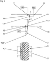
- Fig. 1 shows a positioning mechanism 1 with a spike setting gun 2 with a gun head 3 and a spike feeder 4 and a vehicle pneumatic tire 5 held in a jig 6.
- the pneumatic vehicle tire 5 has a treaded tread and is under internal pressure on the rim of the jig 6, the other components are not shown mounted.
- the clamped vehicle pneumatic tire 5 is rotated stepwise in Bespiken in a conventional manner.
- the spike setting gun 2 is arranged by means of the positioning mechanism 1, as described below, with respect to the pneumatic vehicle tire 5, that their spike setting direction extending main axis a 1 is perpendicular to the tire surface at the respective Spikesetzposition and coaxial with the Spikeloch before each setting process ,
- the positioning mechanism 1 is arranged on a base 7 and actuates a first and a second horizontal slide 8, 9 and a vertical carriage 10 arranged on the two horizontal slides 8, 9, on which the spike setting gun 2 is fastened.
- the positioning mechanism 1 has a first prismatic hinge 11, which allows a linear movement of the first horizontal slide 8 on a linear guide 16, further a second prismatic hinge 12 which, parallel to the direction of movement of the first horizontal slide 8, a linear movement of the second horizontal slide 9 allows a further linear guide 16, and a third and fourth prismatic joint 13, 13 ', which joints 13, 13' a linear movement of the vertical slide 10 transverse to and against the two horizontal slide 8, 9 allow.
- the main axis a 1 of the arranged on the vertical slide 10 spike setting gun 2 extends parallel to the direction of movement of the prismatic joints 13, 13 '.
- Each of the three prismatic joints 11, 12, 13 is programmably controllable by means of actuators, in particular drives M1, M2, M3, in particular by the intended electronic system control.
- Two passive pivots 14, 15 allow an angular movement of the vertical slide 10 relative to the two horizontal slide 8, 9.
- the angle ⁇ of the main axis a 1 of the spike setting gun 2 is compared with an orthogonal to the tire rotation axis a 2, for example ⁇ 15 ° adjustable and changeable.
- the joints referred to as "prismatic joints" 11, 12 and 13 are commonly referred to as push joints or linear joints.
- the horizontal slide 8, 9 can be slidably positioned in provided on the base 7 linear guides 16, such as rails.
- the drives M1, M2 and M3 can be servomotors.
- TCP Toolcenterpoint
- the positioning mechanism 1 is aligned with respect to the vehicle pneumatic tire 5 clamped in such a way that the linear movements of the horizontal slides 8, 9 take place parallel to the tire axis a 2 .
- the spike setting gun 2 In each spike setting position, the spike setting gun 2 is positioned such that its major axis a 1 is orthogonal to the tread surface and coaxial with the respective spike hole.
- the spike setting gun 2 For alignment of the spike setting gun 2 relative to the pneumatic vehicle tire 5, depending on the position to be adjusted, either only one of the driven prismatic joints 11, 12, 13 or two or all three driven prismatic joints 11, 12, 13 are actuated in combination.
- the two horizontal slides 8, 9 are synchronously moved linearly.
- the tool center point of the spike setting gun 2 can be moved toward the pneumatic vehicle tire 5 or away from the pneumatic vehicle tire 5, wherein, for example, for a movement of the TCP orthogonal to the tire axis a 2 with simultaneous angular positioning of the vertical slide 10 also the first and / or. or the second horizontal slide 8, 9 is moved.
- the two horizontal slides 8, 9 are moved in correspondingly different dimensions.
- the positioning mechanism 1 thus allows orthogonal alignment of the major axis a 1 of the spike setting gun 2 to the tire surface at each nip position in the tread, thereby setting the spike in optimum alignment.
- two spike setting guns with positioning mechanisms according to the invention for Bespiken a pneumatic vehicle tire are used, in particular on opposite sides of the pneumatic vehicle tire.
- two different spike types can also be used in the pneumatic vehicle tire. It is irrelevant where spike type is to be placed in the tread, as both spike setting guns can occupy the entire tread width with spikes.
- the cycle time can be reduced because one of the spike setting guns can already be pre-positioned while the other spikes.
- the method for spying on a pneumatic vehicle tire by means of a system or device which has as part of a positioning mechanism according to the invention is explained in more detail below.
- the picking is preferably carried out fully automatically by means of the electronic system control.
- the bespikende pneumatic vehicle tire is first clamped in the chuck 6 and placed under internal pressure.
- image processing which comprises one or more cameras, for example CCD cameras, while the vehicle pneumatic tire is being rotated about its axis of rotation a 2 , the surface contour of the pneumatic vehicle tire is detected, wherein the spike hole positions are also recorded and stored.
- the electronic controller determines, for each trackhole, a data set with the corresponding X and Y coordinates in the working plane of the positioning mechanism, the surface angle, which is the angle between a tangent substantially parallel to the surface at the relevant trackhole and parallel to the axis Tire rotation axis a 2 , as well as with the associated rotational position of the pneumatic vehicle tire. From these data, the target positions of the drives M1, M2 and M3 are determined for a pre-position in which the TCP of the spike setting gun 2 is at a certain distance above the relevant Spikeloch, wherein the axis a 1 is orthogonal to the surface of the pneumatic vehicle tire.
- the drives M1, M2 and M3 are coupled and the TCP is moved from its current position to the preposition to the relevant Spikeloch.
- the vehicle pneumatic tire is rotated to the associated rotational position.
- the drive M3 drives the TCP based on the position data and on the basis of any further specifications, in particular, a predetermined depth of the spike to the appropriate distance.
- the TCP dives into the relevant spikelet at the angle ⁇ . The spike is then placed in the hole and the TCP moved away from the tire surface by returning the drive M3.
- the required data or coordinates of the hole positions can already be predefined and stored in the controller.
- the three drives M1, M2 and M3 can be coupled to each other by means of variable or by means of predetermined coupling factors.
Description
Die Erfindung betrifft einen elektronisch steuerbaren Positioniermechanismus zum Positionieren einer Spike-Setzpistole gegenüber der Oberfläche eines zu bespikenden Fahrzeugluftreifens. Die Erfindung betrifft ferner eine Vorrichtung und ein Verfahren zum Bespiken von Fahrzeugluftreifen mit einer Einspannvorrichtung für den Fahrzeugluftreifen und mit einem Positioniermechanismus.The invention relates to an electronically controllable positioning mechanism for positioning a spike setting gun with respect to the surface of a vehicle pneumatic tire to be spiked. The invention further relates to an apparatus and a method for spying on pneumatic vehicle tires with a clamping device for the pneumatic vehicle tire and with a positioning mechanism.
Die bekannten vollautomatischen Positioniermechanismen für Spike-Setzpistolen erlauben eine Positionierung der Spike-Setzpistole mit zwei Freiheitsgraden, nämlich eine Positionierung parallel zur Reifenachse und eine Positionierung im rechten Winkel zur Reifenachse, um die Spike-Setzpistole dem jeweiligen Reifendurchmesser anzupassen und die Setztiefe einzustellen. Es sind ferner Positioniermechanismen bekannt, bei welchen die Positionierung der Spike-Setzpistole in Querrichtung des Laufstreifens entlang einer Kurvenbahn erfolgt, die der äußeren Kontur der Reifenoberfläche angenähert ist. Es ist daher mit den bekannten Positioniermechanismen nicht möglich, die Hauptachse der Spike-Setzpistole bei allen Setzvorgängen senkrecht zur Reifenoberfläche auszurichten. Die fehlende Orthogonalität der Hauptachse der Spike-Setzpistole führt einerseits dazu, dass die Spikes in manchen Setzpositionen "verkippt" in den Laufstreifen eingesetzt werden, und andererseits dazu, dass der Spikeüberstand je nach Setzposition durch jeweils andere Reibungsverhältnisse beim Setzen "winkelabhängig" variiert.The known fully automatic positioning mechanisms for spike setting guns allow positioning the spike setting gun with two degrees of freedom, namely a position parallel to the tire axis and a positioning at right angles to the tire axis to adjust the spike setting gun to the respective tire diameter and adjust the setting depth. Positioning mechanisms are also known in which the positioning of the spike setting gun in the transverse direction of the tread takes place along a curved path that approximates the outer contour of the tire surface. It is therefore not possible with the known positioning mechanisms to align the main axis of the spike setting gun perpendicular to the tire surface during all setting operations. The lack of orthogonality of the main axis of the spike setting gun leads on the one hand to the spikes being "tilted" into the tread in some placement positions, and on the other to the fact that the spike projection varies depending on the setting position due to different friction conditions when setting "angle-dependent".
Die
Der Erfindung liegt somit die Aufgabe zugrunde, eine Positioniervorrichtung derart auszuführen, dass die Spike-Setzpistole bei allen Setzvorgängen und in allen Setzpositionen senkrecht zur Laufstreifenoberfläche ausgerichtet werden kann, wobei sichergestellt sein soll, dass gegenüber den bekannten Positioniermechanismen zumindest mit gleicher Zykluszeit gearbeitet werden kann. Der Erfindung liegt ferner die Aufgabe zugrunde ein Verfahren zur Verfügung zu stellen, mit welchen auf verlässliche und einfache Weise eine vollautomatisch ablaufende Bespikung eines Fahrzeugluftreifens möglich ist.The invention is thus based on the object to carry out a positioning device such that the spike setting gun can be aligned perpendicular to the tread surface in all setting operations and in all setting positions, it being ensured that compared to the known positioning mechanisms can be used at least with the same cycle time. The invention is further based on the object to provide a method with which a fully automatic running Bespikung a pneumatic vehicle tire is possible in a reliable and simple manner.
Gelöst wird die gestellte Aufgabe gemäß Anspruch 1.The object is solved according to claim 1.
Der erfindungsgemäße Positioniermechanismus gestattet es, die Spike-Setzpistole stufenlos und je Spikesetzvorgang in einem definierten Winkel stets senkrecht zur Reifenoberfläche auszurichten. Der Spike wird somit beim Setzen nicht mehr oder kaum verkippt. Darüber hinaus tritt keine ungleichmäßig verteilte Reibung mehr zwischen dem Spike und dem Gummimaterial um das im Fahrzeugluftreifen einvulkanisierte Spikeloch beim Setzen auf, sodass die Setztiefe der Spikes kaum mehr variiert. Durch die gemäß der Erfindung vorgesehene Kinematik ist ferner sichergestellt, dass trotz einer Erhöhung der Freiheitsgrade durch Einstellbarkeit eines Schwenkwinkels die bewegte Masse des Positioniersystems gegenüber bekannten Positioniersystemen kaum erhöht ist. Es kann daher trotz zusätzlichem Freiheitsgrad mit gleicher Zykluszeit gearbeitet werden. Ein weiterer Vorteil der vorgesehenen Kinematik besteht darin, dass sie bei einer sehr vorteilhaften Beweglichkeit sehr steif ausgeführt werden kann, was eine Voraussetzung für eine hohe Positioniergenauigkeit ist.The positioning mechanism according to the invention makes it possible to align the spike setting gun continuously and per spike setting process at a defined angle always perpendicular to the tire surface. The spike is thus not or hardly tilted when setting. In addition, no unevenly distributed friction occurs between the spike and the rubber material around the in the vehicle pneumatic tire vulcanized Spikeloch on setting, so that the setting depth of the spikes hardly varies. The provided according to the invention kinematics is further ensured that, despite an increase in the degrees of freedom by adjustability of a pivot angle, the moving mass of the positioning system compared to known positioning systems is hardly increased. It can therefore be used despite additional degree of freedom with the same cycle time. Another advantage of the proposed kinematics is that they are at a very advantageous mobility can be carried out very stiff, which is a prerequisite for a high positioning accuracy.
Bei einer bevorzugten Ausführungsform der Erfindung sind die Antriebe Servomotoren, sodass eine sehr exakte und rationell durchführbare Positionierung der Spike-Setzpistole möglich ist.In a preferred embodiment of the invention, the drives are servomotors, so that a very accurate and rationally feasible positioning of the spike setting gun is possible.
Erfindungsgemäß sind ferner die Horizontalschlitten an Linearführungen, beispielsweise Längsschienen, verschiebbar gelagert, die insbesondere an einer stationär positionierten Basis angeordnet sind. Diese Maßnahme ist für einen kompakten Aufbau des Positioniermechanismus von Vorteil.Furthermore, according to the invention, the horizontal slides are displaceably mounted on linear guides, for example longitudinal rails, which are arranged in particular on a stationarily positioned base. This measure is advantageous for a compact construction of the positioning mechanism.
Bei einer weiteren vorteilhaften Ausführungsform der Erfindung ist die Winkelstellung des Vertikalschlittens relativ zu den Horizontalschlitten gegenüber der exakten vertikalen Ausrichtung um etwa ± 15° veränderbar und einstellbar. Diese Maßnahme ermöglicht die Positionierung der Spike-Setzpistole im erforderlichen Bereich.In a further advantageous embodiment of the invention, the angular position of the vertical slide relative to the horizontal slide relative to the exact vertical orientation by about ± 15 ° changeable and adjustable. This measure allows the positioning of the spike setting gun in the required range.
Die erfindungsgemäße Vorrichtung zum Bespiken von Fahrzeugluftreifen weist einen erfindungsgemäß ausgeführten Positioniermechanismus auf, welcher derart gegenüber dem in einer Einspannvorrichtung eingespannten Fahrzeugluftreifen positionierbar ist, dass die Horizontalschlitten parallel zur Reifenachse bewegbar sind und der Vertikalschlitten derart bewegbar ist, dass die Hauptachse der auf ihm befestigten Spike-Setzpistole orthogonal zur Laufstreifenoberfläche des Fahrzeugluftreifens ausrichtbar ist.The device according to the invention for spying on pneumatic vehicle tires has a positioning mechanism according to the invention which is positionable relative to the vehicle pneumatic tire clamped in a clamping device such that the horizontal carriages are movable parallel to the tire axis and the vertical carriage is movable such that the main axis of the spikes mounted thereon is movable. Setting gun is orthogonal to the tread surface of the pneumatic vehicle tire alignable.
Das erfindungsgemäße Verfahren weist folgende Verfahrensschritte auf:
- a) Einspannen des Fahrzeugluftreifens in die Einspannvorrichtung,
- b) Setzen des Fahrzeugluftreifens unter Innendruck,
- c) Verfahren des Toolcenterpoints der Spike-Setzpistole auf Basis von Zielpositionen der Antriebe des Positioniermechanismus in eine Vorposition zu einem Spikeloch und Drehen des Fahrzeugluftreifens in die zugehörige Rotationsposition, wobei in der Vorposition der Toolcenterpoint der Spike-Setzpistole in einem Abstand über dem betreffenden Spikeloch liegt und die Achse der Spike-Setzpistole orthogonal zur Reifenoberfläche an der Spikesetzposition steht,
- d) Verfahren der Spike-Setzpistole aus der Vorposition durch Ausfahren des entsprechenden Antriebes bis der Toolcenterpoint in das betreffende Spikeloch eintaucht,
- e) Setzen des Spikes in das Spikeloch,
- f) Zurückfahren des Toolcenterpoints durch Zurückfahren des Antriebes,
- g) Wiederholung der Verfahrensschritte a) bis f), bis alle Spikelöcher mit Spikes versehen sind und
- h) Entlüften und Ausspannen des Fahrzeugluftreifens.
- a) clamping the pneumatic vehicle tire in the clamping device,
- b) setting the pneumatic vehicle tire under internal pressure,
- c) method of the tool center point of the spike setting gun based on target positions of the drives of the positioning mechanism in a pre-position to a Spikeloch and turning the pneumatic vehicle tire in the associated rotational position, wherein in the pre-position of the tool center point of the spike setting gun at a distance the spikelet hole in question and the axis of the spike setting gun is orthogonal to the tire surface at the nip position,
- d) moving the spike setting gun from the pre-position by extending the corresponding drive until the Toolcenterpoint dives into the relevant spike hole,
- e) placing the spike in the spike hole,
- f) returning the toolcenter point by returning the drive,
- g) repetition of the method steps a) to f) until all the spikelet holes are provided with spikes and
- h) Bleeding and Unclamping the pneumatic vehicle tire.
Der Toolcenterpoint befindet sich an der Spitze der Spike-Setzpistole und korreliert mit der jeweiligen Spikesetzposition.The Toolcenterpoint is located at the top of the spike setting gun and correlates with the respective spikesetting position.
Vorteilhafterweise werden die Zielpositionen der Antriebe des Positioniermechanismus jeweils auf Basis eines Datensatzes bestimmt, zu welchen Daten die X-Y-Koordinaten jeder Spike-Lochposition in der Antriebsebene des Positioniermechanismus, der Oberflächenwinkel an jeder Spike-Lochposition und die Rotationsposition des Fahrzeugluftreifens gehören, so dass die Antriebe für jede Spike-Lochposition in die zugehörige Position verfahrbar sind.Advantageously, the target positions of the actuators of the positioning mechanism are respectively determined on the basis of a data set, which data include the XY coordinates of each spike hole position in the drive plane of the positioning mechanism, the surface angle at each spike hole position and the rotational position of the pneumatic vehicle tire, so that the drives be moved for each spike hole position in the associated position.
Bei einer erfindungsgemäßen Ausführungsform des Verfahrens werden der Oberflächenwinkel und die Spike-Lochpositionen während des Drehens des Fahrzeugluftreifens um seine Drehachse mittels zumindest einer Kamera erfasst, so dass die Grunddaten zur Bestimmung des Datensatzes für jeden Fahrzeugluftreifen individuell ermittelt werden und eventuelle Fertigungstoleranzen der einzelnen Fahrzeugluftreifen ausgeglichen werden können.In an embodiment of the method according to the invention, the surface angle and the spike hole positions are detected during rotation of the pneumatic vehicle tire around its axis of rotation by means of at least one camera, so that the basic data for determining the data set for each pneumatic vehicle tire are determined individually and possible manufacturing tolerances of the individual pneumatic vehicle tires are compensated can.
Alternativ oder zusätzlich können die Zielpositionen der Antriebe des Positioniermechanismus aus Daten bzw. Koordinaten der Spike-Lochpositionen bestimmt werden, die innerhalb der Steuerung und von einer externen Datenerfassung bzw. einem externen Datenspeicher vorgegeben und abgespeichert sind.Alternatively or additionally, the target positions of the drives of the positioning mechanism can be determined from data or coordinates of the spike hole positions which are predetermined and stored within the controller and by an external data acquisition or an external data memory.
Bei einer vorteilhaften Ausführungsform des erfindungsgemäßen Verfahrens werden die Antriebe mittels variabler Koppelfaktoren gekoppelt, so dass sich die Geschwindigkeitsverhältnisse der einzelnen Antriebe zueinander während der Bewegung ändern können. Somit sind einzelne Zielpositionen schnell und genau anfahrbar.In an advantageous embodiment of the method according to the invention, the drives are coupled by means of variable coupling factors, so that the speed ratios of the individual drives to each other during the movement can change. Thus, individual target positions can be approached quickly and accurately.
Alternativ können die Antriebe auch mittels fester Koppelfaktoren gekoppelt werden, so dass die Geschwindigkeiten der einzelnen Antriebe stets in einem festen Verhältnis zueinander stehen, was insbesondere die mechanische Belastung des Positioniersystems verringern kann.Alternatively, the drives can also be coupled by means of fixed coupling factors, so that the speeds of the individual drives are always in a fixed relationship to one another, which in particular can reduce the mechanical load on the positioning system.
Weitere Merkmale, Vorteile und Einzelheiten der Erfindung werden nun anhand der Zeichnung, die schematisch ein Ausführungsbeispiel der Erfindung darstellt, näher beschrieben. Dabei zeigen
- Fig. 1
- eine schematische Ansicht eines Positioniermechanismus gemäß der Erfindung und
- Fig. 2
- eine Prinzipskizze des Positioniermechanismus.
- Fig. 1
- a schematic view of a positioning mechanism according to the invention and
- Fig. 2
- a schematic diagram of the positioning mechanism.
Die Erfindung befasst sich mit einer Vorrichtung zum Bespiken von Laufstreifen von Fahrzeugluftreifen mit einer Spike-Setzpistole, deren Ausrichtung gegenüber einem Laufstreifen eines Fahrzeugluftreifens mittels eines Positioniermechanismus variabel einstellbar ist.The invention relates to a device for spying on treads of pneumatic vehicle tires with a spike setting gun whose orientation relative to a tread of a pneumatic vehicle tire by means of a positioning mechanism is variably adjustable.
Die Spike-Setzpistole 2 wird mittels des Positioniermechanismus 1, wie weiter unten beschrieben wird, derart gegenüber dem Fahrzeugluftreifen 5 angeordnet, dass sich ihre in Spike-Setzrichtung erstreckende Hauptachse a1 vor jedem Setzvorgang senkrecht zur Reifenoberfläche an der jeweiligen Spikesetzposition und koaxial zum Spikeloch befindet.The
Der Positioniermechanismus 1 ist auf einer Basis 7 angeordnet und betätigt einen ersten und einen zweiten Horizontalschlitten 8, 9 sowie einen auf den beiden Horizontalschlitten 8, 9 angeordneten Vertikalschlitten 10, auf welchem die Spike-Setzpistole 2 befestigt ist. Der Positioniermechanismus 1 weist ein erstes prismatisches Gelenk 11 auf, welches eine lineare Bewegung des ersten Horizontalschlittens 8 auf einer Linearführung 16 ermöglicht, ferner ein zweites prismatisches Gelenk 12, welches, parallel zur Bewegungsrichtung des ersten Horizontalschlittens 8, eine lineare Bewegung des zweiten Horizontalschlittens 9 auf einer weiteren Linearführung 16 ermöglicht, sowie ein drittes und viertes prismatisches Gelenk 13, 13', welche Gelenke 13, 13' eine lineare Bewegung des Vertikalschlittens 10 quer zu und gegenüber den beiden Horizontalschlitten 8, 9 ermöglichen. Die Hauptachse a1 der auf dem Vertikalschlitten 10 angeordneten Spike-Setzpistole 2 verläuft parallel zur Bewegungsrichtung der prismatischen Gelenke 13, 13'. Die drei prismatischen Gelenke 11, 12, 13 sind, jedes für sich, mittels Stellgliedern, insbesondere Antrieben M1, M2, M3, programmierbar steuerbar, insbesondere durch die vorgesehene elektronische Anlagensteuerung. Zwei passive Drehgelenke 14, 15 gestatten eine Winkelbewegung des Vertikalschlittens 10 gegenüber den beiden Horizontalschlitten 8, 9. Der Winkel α der Hauptachse a1 der Spike-Setzpistole 2 ist gegenüber einer Orthogonalen zur Reifendrehachse a2 um beispielsweise ± 15° einstell- und veränderbar.The positioning mechanism 1 is arranged on a
Die als "prismatische Gelenke" 11, 12 und 13 bezeichneten Gelenke werden üblicherweise auch als Schubgelenke oder Lineargelenke bezeichnet.The joints referred to as "prismatic joints" 11, 12 and 13 are commonly referred to as push joints or linear joints.
Die Horizontalschlitten 8, 9 können in an der Basis 7 vorgesehenen Linearführungen 16, beispielsweise Schienen, verschiebbar positioniert sein. Die Antriebe M1, M2 und M3 können Servomotoren sein.The
Zur Ausrichtung der Spike-Setzpistole 2 zum Fahrzeugluftreifen 5 wird ihr Toolcenterpoint (TCP), welcher sich an der Spitze des Pistolenkopfes 3 auf der Hauptachse a1 befindet und mit der jeweiligen Spikesetzposition korreliert, automatisch über die elektronische Steuerung der Anlage eingestellt.To align the
Der Positioniermechanismus 1 wird gegenüber dem aufgespannten Fahrzeugluftreifen 5 derart ausgerichtet, dass die linearen Bewegungen der Horizontalschlitten 8, 9 parallel zur Reifenachse a2 erfolgen. In jeder Spike-Setzposition wird die Spike-Setzpistole 2 derart positioniert, dass ihre Hauptachse a1 orthogonal zur Laufstreifenoberfläche und koaxial zum betreffenden Spikeloch verläuft.The positioning mechanism 1 is aligned with respect to the vehicle
Zur Ausrichtung der Spike-Setzpistole 2 gegenüber dem Fahrzeugluftreifen 5 wird je nach einzustellender Position entweder nur eines der angetriebenen prismatischen Gelenke 11, 12, 13 oder es werden zwei oder alle drei angetriebenen prismatischen Gelenke 11, 12, 13 in Kombination miteinander betätigt. Um beispielsweise die Spike-Setzpistole 2 in axialer Richtung des Fahrzeugluftreifens zu bewegen, ohne dabei die Winkelstellung der Hauptachse a1 der Spike-Setzpistole 2 zu verändern, werden die beiden Horizontalschlitten 8, 9 entsprechend synchron linear bewegt. Mittels des dritten prismatischen Gelenkes 13 kann der Toolcenterpoint der Spike-Setzpistole 2 zum Fahrzeugluftreifen 5 hin oder vom Fahrzeugluftreifen 5 weg bewegt werden, wobei beispielsweise für eine orthogonal zur Reifenachse a2 gerichtete Bewegung des TCP bei gleichzeitiger Winkelstellung des Vertikalschlittens 10 auch der erste und/oder der zweite Horizontalschlitten 8, 9 bewegt wird. Zum Ändern der Winkeleinstellung (Winkel a) der Hauptachse a1 der Spike-Setzpistole 2 werden die beiden Horizontalschlitten 8, 9 in entsprechend unterschiedlichen Ausmaßen bewegt.For alignment of the
Der Positioniermechanismus 1 ermöglicht daher eine orthogonale Ausrichtung der Hauptachse a1 der Spike-Setzpistole 2 zur Reifenoberfläche an jeder Spikesetzposition im Laufstreifen, wodurch der Spike mit optimaler Ausrichtung gesetzt wird.The positioning mechanism 1 thus allows orthogonal alignment of the major axis a 1 of the
Bei einer weiteren, nicht gezeigten Ausführungsvariante der Erfindung können in einer Anlage zwei Spike-Setzpistolen mit erfindungsgemäßen Positioniermechanismen zum Bespiken eines Fahrzeugluftreifens verwendet werden, insbesondere an einander gegenüberliegenden Seiten des Fahrzeugluftreifens. Bei dieser Ausführungsvariante können ferner zwei unterschiedliche Spiketypen in den Fahrzeugluftreifen eingesetzt werden. Dabei ist es unwesentlich, wo welcher Spiketyp in den Laufstreifen gesetzt werden soll, da beide Spike-Setzpistolen die gesamte Laufstreifenbreite mit Spikes besetzen können. Durch die Verwendung von zwei Spike-Setzpistolen an einem Fahrzeugluftreifen kann die Zykluszeit verringert werden, da eine der Spike-Setzpistolen bereits vorpositioniert werden kann, während die andere einen Spike setzt.In a further, not shown embodiment of the invention, two spike setting guns with positioning mechanisms according to the invention for Bespiken a pneumatic vehicle tire are used, in particular on opposite sides of the pneumatic vehicle tire. In this embodiment, two different spike types can also be used in the pneumatic vehicle tire. It is irrelevant where spike type is to be placed in the tread, as both spike setting guns can occupy the entire tread width with spikes. By using two spike setting guns on a pneumatic vehicle tire, the cycle time can be reduced because one of the spike setting guns can already be pre-positioned while the other spikes.
Das Verfahren zum Bespiken eines Fahrzeugluftreifens mittels einer Anlage oder Vorrichtung, die als Bestandteil einen erfindungsgemäßen Positioniermechanismus aufweist, wird im Folgenden näher erläutert. Wie bereits erwähnt wird das Bespiken vorzugsweise vollautomatisch mittels der elektronischen Anlagensteuerung durchgeführt. Der zu bespikende Fahrzeugluftreifen wird zuerst in die Einspannvorrichtung 6 eingespannt und unter Innendruck gesetzt. Mittels einer Bildverarbeitung, die eine oder mehrere Kameras, beispielsweise CCD-Kameras, umfasst, wird, während der Fahrzeugluftreifen um seine Drehachse a2 gedreht wird, die Oberflächenkontur des Fahrzeugluftreifens erfasst, wobei die Spike-Lochpositionen miterfasst und abgespeichert werden.The method for spying on a pneumatic vehicle tire by means of a system or device which has as part of a positioning mechanism according to the invention is explained in more detail below. As already mentioned, the picking is preferably carried out fully automatically by means of the electronic system control. The bespikende pneumatic vehicle tire is first clamped in the
Die elektronische Steuerung bestimmt für jedes Spikeloch einen Datensatz mit den entsprechenden X- und Y-Koordinaten in der Arbeitsebene des Positioniermechanismus, dem Oberflächenwinkel, dies ist der Winkel zwischen einer im Wesentlichen in axialer Richtung an die Oberfläche am betreffenden Spikeloch gelegten Tangente und einer Parallelen zur Reifendrehachse a2, sowie mit der zugehörigen Rotationposition des Fahrzeugluftreifens. Aus diesen Daten werden die Zielpositionen der Antriebe M1, M2 und M3 für eine Vorposition bestimmt, in welcher der TCP der Spike-Setzpistole 2 in einem gewissen Abstand über dem betreffenden Spikeloch liegt, wobei die Achse a1 orthogonal zur Oberfläche des Fahrzeugluftreifens steht. Dazu werden die Antriebe M1, M2 und M3 gekoppelt und der TCP wird aus seiner aktuellen Position in die Vorposition zum betreffenden Spikeloch bewegt. Insbesondere gleichzeitig wird der Fahrzeugluftreifen in die zugehörige Rotationsposition gedreht. Sind diese Positionen erreicht, fährt der Antrieb M3 den TCP auf Basis der Positionsdaten und auf Basis etwaiger weiterer Vorgaben, insbesondere einer vorgegebenen Setztiefe des Spikes, um die entsprechende Strecke aus. Dabei taucht der TCP im Winkel α in das betreffende Spikeloch ein. Anschließend wird der Spike in das Loch gesetzt und der TCP durch Zurückfahren des Antriebes M3 von der Reifenoberfläche wegbewegt.The electronic controller determines, for each trackhole, a data set with the corresponding X and Y coordinates in the working plane of the positioning mechanism, the surface angle, which is the angle between a tangent substantially parallel to the surface at the relevant trackhole and parallel to the axis Tire rotation axis a 2 , as well as with the associated rotational position of the pneumatic vehicle tire. From these data, the target positions of the drives M1, M2 and M3 are determined for a pre-position in which the TCP of the
Die betreffenden Schritte werden automatisch wiederholt, bis alle Spikelöcher im Laufstreifen mit Spikes versehen sind. Ist der Fahrzeugluftreifen komplett bespiket, wird er entlüftet und aus der Einspannvorrichtung 6 entfernt.These steps are repeated automatically until all the stud holes in the tread are spiked. If the vehicle pneumatic tire is completely spiked, it is vented and removed from the
Alternativ zu einer Erfassung der Position der Löcher mittels zumindest einer Kamera können die erforderlichen Daten bzw. Koordinaten der Lochpositionen, etwa aus den Herstelldaten des betreffenden Fahrzeugluftreifens, bereits in der Steuerung vorgegeben und abgespeichert sein. Es können ferner die drei Antriebe M1, M2 und M3 mittels variabler oder mittels vorgegebener Koppelfaktoren miteinander gekoppelt werden.As an alternative to detecting the position of the holes by means of at least one camera, the required data or coordinates of the hole positions, for example from the manufacturing data of the relevant pneumatic vehicle tire, can already be predefined and stored in the controller. Furthermore, the three drives M1, M2 and M3 can be coupled to each other by means of variable or by means of predetermined coupling factors.
- 11
- Positioniermechanismuspositioning
- 22
- Spike-SetzpistoleSpike-setting gun
- 33
- Pistolenkopfgun head
- 44
- Zuführeinrichtungfeeding
- 55
- FahrzeugluftreifenVehicle tires
- 66
- Einspannvorrichtungchuck
- 77
- BasisBase
- 8, 98, 9
- Horizontalschlittenhorizontal slide
- 1010
- Vertikalschlittenvertical slide
- 11, 12, 13, 13'11, 12, 13, 13 '
- prismatisches Gelenkprismatic joint
- 14, 1514, 15
- Drehgelenkswivel
- 1616
- Linearführunglinear guide
- a1 a 1
- Hauptachsemain axis
- a2 a 2
- Reifenachsetire axis
- M1, M2, M3M1, M2, M3
- Antriebdrive
- αα
- Winkelangle
Claims (11)
- Electronically controllable positioning mechanism (1) for positioning a spike setting pistol (2) relative to the surface of a vehicle pneumatic tyre (5) to be spiked, having- a first prismatic joint (11), which permits the movement of a first horizontal slide (8) of the positioning mechanism relative to a base (7),- a second prismatic joint (12), which, parallel to the movement of the first horizontal slide (8), permits the movement of a second horizontal slide (9) of the positioning mechanism relative to the base (7),- at least one further prismatic joint (13, 13'), which, substantially transversely with respect to the direction of movement of the horizontal slides (8, 9), permits the movement of a vertical slide (10) of the positioning mechanism relative to the two horizontal slides (8, 9),- two rotary joints (14, 15), which permit an angular movement of the vertical slide (10) in relation to the horizontal slides (8, 9),wherein the spike setting pistol (2) is arranged on the vertical slide (10) in such a manner that its main axis (a1) running in the spike setting direction is oriented parallel to the guiding direction of the at least one further prismatic joint (13, 13'), and wherein the first, the second and the at least one further prismatic joint (11, 12, 13, 13') are actuable by means of one drive (M1, M2, M3) each.
- Positioning mechanism (1) according to Claim 1, characterized in that the drives (M1, M2, M3) are servomotors.
- Positioning mechanism (1) according to Claim 1 or 2, characterized in that the horizontal slides (8, 9) are mounted displaceably on linear guides (16) of a base (7).
- Positioning mechanism (1) according to one of Claims 1 to 3, characterized in that the angular position of the vertical slide (10) is adjustable and changeable by approx. ±15° relative to an orthogonal to the axis of rotation (a2) of the tyre.
- Device for spiking vehicle pneumatic tyres, with a clamping device (6) for the vehicle pneumatic tyre (5) and with a positioning mechanism (1) according to one or more of Claims 1 to 4, characterized in that the positioning mechanism (1) can be positioned in relation to the clamped vehicle pneumatic tyre (5) in such a manner that the horizontal slides (8, 9) are movable parallel to the tyre axis (a2) and the vertical slide (10) is movable in such a manner that the main axis (a1) of the spike setting pistol (2) fastened on said vertical slide can be oriented orthogonally to the tread surface of the vehicle pneumatic tyre.
- Method for spiking vehicle pneumatic tyres by means of a device according to Claim 5, with the following method steps:a) clamping the vehicle pneumatic tyre (5) in the clamping device (6),b) setting the vehicle pneumatic tyre (5) under internal pressure,c) moving a tool centre point of the spike setting pistol (2) on the basis of target positions of the drives (M1, M2, M3) of the positioning mechanism (1) into a preliminary position with respect to a spike hole and rotating the vehicle pneumatic tyre (5) into the associated rotational position, wherein, in the preliminary position of the tool centre point, the spike setting pistol (2) lies at a distance above the relevant spike hole and the axis (a1) of the spike setting pistol (2) is orthogonal to the tyre surface at the spike setting position,d) moving the spike setting pistol (2) out of the preliminary position by extending the corresponding drive (M3) until the tool centre point enters the relevant spike hole,e) setting the spike into the spike hole,f) retracting the tool centre point by retracting the drive (M3),g) repeating method steps a) to f) until all of the spike holes are provided with spikes, andh) venting and unclamping the vehicle pneumatic tyre (5) .
- Method according to Claim 6, characterized in that the target positions of the drives (M1, M2, M3) of the positioning mechanism (1) are in each case determined on the basis of a data set, the data of which includes the X-Y coordinates of each spike hole position in the working plane of the positioning mechanism (1), the surface angle at each spike hole position and the rotational position of the vehicle pneumatic tyre.
- Method according to Claim 6 or 7, characterized by detecting the surface angles and the spike hole positions during the rotation of the vehicle pneumatic tyre (5) about its axis of rotation (a2) by means of at least one camera.
- Method according to Claim 6, characterized in that the target positions of the drives (M1, M2, M3) of the positioning mechanism (1) are determined from data or coordinates of the spike hole positions which are predetermined and stored.
- Method according to one of Claims 6 to 9, characterized in that the drives (M1, M2, M3) are coupled by means of variable coupling factors.
- Method according to one of Claims 6 to 9, characterized in that the drives (M1, M2, M3) are coupled by means of fixed coupling factors.
Priority Applications (1)
| Application Number | Priority Date | Filing Date | Title |
|---|---|---|---|
| EP15165733.5A EP3088170B1 (en) | 2015-04-29 | 2015-04-29 | Positioning mechanism for positioning a spike setting pistol relative to a vehicle pneumatic tire, and device and method for spiking a pneumatic vehicle tyre |
Applications Claiming Priority (1)
| Application Number | Priority Date | Filing Date | Title |
|---|---|---|---|
| EP15165733.5A EP3088170B1 (en) | 2015-04-29 | 2015-04-29 | Positioning mechanism for positioning a spike setting pistol relative to a vehicle pneumatic tire, and device and method for spiking a pneumatic vehicle tyre |
Publications (2)
| Publication Number | Publication Date |
|---|---|
| EP3088170A1 EP3088170A1 (en) | 2016-11-02 |
| EP3088170B1 true EP3088170B1 (en) | 2019-09-18 |
Family
ID=53015671
Family Applications (1)
| Application Number | Title | Priority Date | Filing Date |
|---|---|---|---|
| EP15165733.5A Active EP3088170B1 (en) | 2015-04-29 | 2015-04-29 | Positioning mechanism for positioning a spike setting pistol relative to a vehicle pneumatic tire, and device and method for spiking a pneumatic vehicle tyre |
Country Status (1)
| Country | Link |
|---|---|
| EP (1) | EP3088170B1 (en) |
Families Citing this family (6)
| Publication number | Priority date | Publication date | Assignee | Title |
|---|---|---|---|---|
| FI127522B (en) * | 2017-02-06 | 2018-08-15 | Nokian Renkaat Oyj | A device for studding a tire |
| EP3904065B1 (en) * | 2017-02-06 | 2023-11-08 | Nokian Renkaat Oyj | A device for studding a tire |
| RU2716522C1 (en) * | 2017-02-28 | 2020-03-12 | Дзе Йокогама Раббер Ко., Лтд. | Stud pin and studded tire |
| DE102019207430A1 (en) | 2019-05-21 | 2020-11-26 | Continental Reifen Deutschland Gmbh | Electronically controlled positioning system |
| CN113942258B (en) * | 2021-09-24 | 2022-07-08 | 河北正固橡胶科技有限公司 | Tire blank pressure head punching equipment for forming of hand cart tire |
| CN116728536B (en) * | 2023-08-10 | 2023-10-27 | 常州顺联橡胶机械有限公司 | Full-automatic nailing machine for anti-skid tyre and use method thereof |
Family Cites Families (8)
| Publication number | Priority date | Publication date | Assignee | Title |
|---|---|---|---|---|
| DE1255299B (en) * | 1964-05-15 | 1967-11-30 | Metzeler Ag | Device for inserting anti-skid pins into prepared holes in the tread of a heated vehicle tire |
| US3520528A (en) * | 1967-03-07 | 1970-07-14 | Kurz Oku Automatik | Spike inserting machine |
| JPS562565Y2 (en) * | 1976-06-11 | 1981-01-21 | ||
| JPS5795203A (en) * | 1980-12-03 | 1982-06-14 | Bridgestone Corp | Method and apparatus for mounting spike into tire |
| SE443324B (en) * | 1984-05-10 | 1986-02-24 | Mekrapid | Studding machine |
| RU2138403C1 (en) * | 1998-03-17 | 1999-09-27 | Корниенко Александр Васильевич | Tyre studding semiautomatic machine, stud fitting device and its head, and method of tyre studding |
| US20020069948A1 (en) * | 2000-12-07 | 2002-06-13 | Sentmanat Martin Lamar | Polymeric product containing precisely located and precisely oriented ingredients |
| RU2216452C2 (en) * | 2001-08-03 | 2003-11-20 | Открытое акционерное общество "Нижнекамскшина" | Tire stud fitting machine (versions) |
-
2015
- 2015-04-29 EP EP15165733.5A patent/EP3088170B1/en active Active
Non-Patent Citations (1)
| Title |
|---|
| None * |
Also Published As
| Publication number | Publication date |
|---|---|
| EP3088170A1 (en) | 2016-11-02 |
Similar Documents
| Publication | Publication Date | Title |
|---|---|---|
| EP3088170B1 (en) | Positioning mechanism for positioning a spike setting pistol relative to a vehicle pneumatic tire, and device and method for spiking a pneumatic vehicle tyre | |
| EP2641669B1 (en) | Shaping machine, in particular bending machine and method for reconfigurating such a shaping machine | |
| DE2556098A1 (en) | METHOD AND DEVICE FOR INSERTING A PEN INTO A COMPLEMENTARY HOLE OF A WORKPIECE | |
| EP3453487B1 (en) | Method for positioning a centre on a geometric axis in a machine tool | |
| DE102018118031A1 (en) | Processing device and method for processing | |
| EP1616661A1 (en) | Workpiece changing device for machine tools | |
| DE19614740A1 (en) | Method and device for printing self-supporting individual objects | |
| EP0433895A1 (en) | Method of detecting the presence or the dimensions or the correct position of a workpiece on a machine tool | |
| DE102020205352A1 (en) | System for automatically setting a wheel alignment | |
| DE102017121526A1 (en) | Device for aligning and positioning a workpiece relative to a laser beam of a laser processing machine | |
| WO2021209230A1 (en) | Device and method for gripping an object | |
| DE2734804A1 (en) | METHOD AND DEVICE FOR AUTOMATIC SIDE ADJUSTMENT OF A WORKPIECE ON A MACHINE TOOL | |
| EP3031572A1 (en) | Tool exchange apparatus for use in a machining centre and machining centre for machining a workpiece | |
| EP3034287A1 (en) | Device for the production of core assemblies for vehicle tyres | |
| EP3750700B1 (en) | Electronically controlled positioning system with a spike setting pistol | |
| EP4275801A1 (en) | Sealant applying station and mounting system for joining components | |
| DE102013215430B4 (en) | processing device | |
| DE102013105719B4 (en) | Detecting device for detecting angles of rotation of a puncture cannula | |
| EP3119540A1 (en) | Drive device for driving a tool slide in a folding system | |
| DE102022107995A1 (en) | Distributed assembly system and method of assembling a workpiece | |
| DE102006013145A1 (en) | Window frame`s individual edge area processing method, involves moving and clamping window frame positioned in area of grippers in processing position, processing moved edge area, releasing frame and repeating movement and processing cycles | |
| DE102020002322B4 (en) | System for processing workpieces made of wood, plastic, aluminum and the like, and method for transferring workpieces between a first and a second clamping device | |
| EP3081330B1 (en) | Device for inserting workpieces or tools into a machine tool | |
| WO2021115736A1 (en) | Device and method for gripping an object | |
| DE102022111519A1 (en) | Assembly tool and assembly system for connecting components |
Legal Events
| Date | Code | Title | Description |
|---|---|---|---|
| PUAI | Public reference made under article 153(3) epc to a published international application that has entered the european phase |
Free format text: ORIGINAL CODE: 0009012 |
|
| AK | Designated contracting states |
Kind code of ref document: A1 Designated state(s): AL AT BE BG CH CY CZ DE DK EE ES FI FR GB GR HR HU IE IS IT LI LT LU LV MC MK MT NL NO PL PT RO RS SE SI SK SM TR |
|
| AX | Request for extension of the european patent |
Extension state: BA ME |
|
| 17P | Request for examination filed |
Effective date: 20170502 |
|
| RBV | Designated contracting states (corrected) |
Designated state(s): AL AT BE BG CH CY CZ DE DK EE ES FI FR GB GR HR HU IE IS IT LI LT LU LV MC MK MT NL NO PL PT RO RS SE SI SK SM TR |
|
| STAA | Information on the status of an ep patent application or granted ep patent |
Free format text: STATUS: REQUEST FOR EXAMINATION WAS MADE |
|
| GRAP | Despatch of communication of intention to grant a patent |
Free format text: ORIGINAL CODE: EPIDOSNIGR1 |
|
| STAA | Information on the status of an ep patent application or granted ep patent |
Free format text: STATUS: GRANT OF PATENT IS INTENDED |
|
| INTG | Intention to grant announced |
Effective date: 20190528 |
|
| GRAS | Grant fee paid |
Free format text: ORIGINAL CODE: EPIDOSNIGR3 |
|
| GRAA | (expected) grant |
Free format text: ORIGINAL CODE: 0009210 |
|
| STAA | Information on the status of an ep patent application or granted ep patent |
Free format text: STATUS: THE PATENT HAS BEEN GRANTED |
|
| AK | Designated contracting states |
Kind code of ref document: B1 Designated state(s): AL AT BE BG CH CY CZ DE DK EE ES FI FR GB GR HR HU IE IS IT LI LT LU LV MC MK MT NL NO PL PT RO RS SE SI SK SM TR |
|
| REG | Reference to a national code |
Ref country code: GB Ref legal event code: FG4D Free format text: NOT ENGLISH |
|
| REG | Reference to a national code |
Ref country code: CH Ref legal event code: EP |
|
| REG | Reference to a national code |
Ref country code: DE Ref legal event code: R096 Ref document number: 502015010374 Country of ref document: DE |
|
| REG | Reference to a national code |
Ref country code: AT Ref legal event code: REF Ref document number: 1180785 Country of ref document: AT Kind code of ref document: T Effective date: 20191015 |
|
| REG | Reference to a national code |
Ref country code: IE Ref legal event code: FG4D Free format text: LANGUAGE OF EP DOCUMENT: GERMAN |
|
| REG | Reference to a national code |
Ref country code: NL Ref legal event code: MP Effective date: 20190918 |
|
| PG25 | Lapsed in a contracting state [announced via postgrant information from national office to epo] |
Ref country code: HR Free format text: LAPSE BECAUSE OF FAILURE TO SUBMIT A TRANSLATION OF THE DESCRIPTION OR TO PAY THE FEE WITHIN THE PRESCRIBED TIME-LIMIT Effective date: 20190918 Ref country code: LT Free format text: LAPSE BECAUSE OF FAILURE TO SUBMIT A TRANSLATION OF THE DESCRIPTION OR TO PAY THE FEE WITHIN THE PRESCRIBED TIME-LIMIT Effective date: 20190918 Ref country code: SE Free format text: LAPSE BECAUSE OF FAILURE TO SUBMIT A TRANSLATION OF THE DESCRIPTION OR TO PAY THE FEE WITHIN THE PRESCRIBED TIME-LIMIT Effective date: 20190918 Ref country code: BG Free format text: LAPSE BECAUSE OF FAILURE TO SUBMIT A TRANSLATION OF THE DESCRIPTION OR TO PAY THE FEE WITHIN THE PRESCRIBED TIME-LIMIT Effective date: 20191218 Ref country code: NO Free format text: LAPSE BECAUSE OF FAILURE TO SUBMIT A TRANSLATION OF THE DESCRIPTION OR TO PAY THE FEE WITHIN THE PRESCRIBED TIME-LIMIT Effective date: 20191218 Ref country code: FI Free format text: LAPSE BECAUSE OF FAILURE TO SUBMIT A TRANSLATION OF THE DESCRIPTION OR TO PAY THE FEE WITHIN THE PRESCRIBED TIME-LIMIT Effective date: 20190918 |
|
| REG | Reference to a national code |
Ref country code: LT Ref legal event code: MG4D |
|
| PG25 | Lapsed in a contracting state [announced via postgrant information from national office to epo] |
Ref country code: RS Free format text: LAPSE BECAUSE OF FAILURE TO SUBMIT A TRANSLATION OF THE DESCRIPTION OR TO PAY THE FEE WITHIN THE PRESCRIBED TIME-LIMIT Effective date: 20190918 Ref country code: GR Free format text: LAPSE BECAUSE OF FAILURE TO SUBMIT A TRANSLATION OF THE DESCRIPTION OR TO PAY THE FEE WITHIN THE PRESCRIBED TIME-LIMIT Effective date: 20191219 Ref country code: LV Free format text: LAPSE BECAUSE OF FAILURE TO SUBMIT A TRANSLATION OF THE DESCRIPTION OR TO PAY THE FEE WITHIN THE PRESCRIBED TIME-LIMIT Effective date: 20190918 Ref country code: AL Free format text: LAPSE BECAUSE OF FAILURE TO SUBMIT A TRANSLATION OF THE DESCRIPTION OR TO PAY THE FEE WITHIN THE PRESCRIBED TIME-LIMIT Effective date: 20190918 |
|
| REG | Reference to a national code |
Ref country code: CH Ref legal event code: PUE Owner name: BECKHOFF AUTOMATION GMBH, DE Free format text: FORMER OWNER: BECKHOFF AUTOMATION GMBH, DE |
|
| PG25 | Lapsed in a contracting state [announced via postgrant information from national office to epo] |
Ref country code: RO Free format text: LAPSE BECAUSE OF FAILURE TO SUBMIT A TRANSLATION OF THE DESCRIPTION OR TO PAY THE FEE WITHIN THE PRESCRIBED TIME-LIMIT Effective date: 20190918 Ref country code: ES Free format text: LAPSE BECAUSE OF FAILURE TO SUBMIT A TRANSLATION OF THE DESCRIPTION OR TO PAY THE FEE WITHIN THE PRESCRIBED TIME-LIMIT Effective date: 20190918 Ref country code: EE Free format text: LAPSE BECAUSE OF FAILURE TO SUBMIT A TRANSLATION OF THE DESCRIPTION OR TO PAY THE FEE WITHIN THE PRESCRIBED TIME-LIMIT Effective date: 20190918 Ref country code: NL Free format text: LAPSE BECAUSE OF FAILURE TO SUBMIT A TRANSLATION OF THE DESCRIPTION OR TO PAY THE FEE WITHIN THE PRESCRIBED TIME-LIMIT Effective date: 20190918 Ref country code: PL Free format text: LAPSE BECAUSE OF FAILURE TO SUBMIT A TRANSLATION OF THE DESCRIPTION OR TO PAY THE FEE WITHIN THE PRESCRIBED TIME-LIMIT Effective date: 20190918 Ref country code: PT Free format text: LAPSE BECAUSE OF FAILURE TO SUBMIT A TRANSLATION OF THE DESCRIPTION OR TO PAY THE FEE WITHIN THE PRESCRIBED TIME-LIMIT Effective date: 20200120 |
|
| PG25 | Lapsed in a contracting state [announced via postgrant information from national office to epo] |
Ref country code: IS Free format text: LAPSE BECAUSE OF FAILURE TO SUBMIT A TRANSLATION OF THE DESCRIPTION OR TO PAY THE FEE WITHIN THE PRESCRIBED TIME-LIMIT Effective date: 20200224 Ref country code: SK Free format text: LAPSE BECAUSE OF FAILURE TO SUBMIT A TRANSLATION OF THE DESCRIPTION OR TO PAY THE FEE WITHIN THE PRESCRIBED TIME-LIMIT Effective date: 20190918 Ref country code: SM Free format text: LAPSE BECAUSE OF FAILURE TO SUBMIT A TRANSLATION OF THE DESCRIPTION OR TO PAY THE FEE WITHIN THE PRESCRIBED TIME-LIMIT Effective date: 20190918 Ref country code: CZ Free format text: LAPSE BECAUSE OF FAILURE TO SUBMIT A TRANSLATION OF THE DESCRIPTION OR TO PAY THE FEE WITHIN THE PRESCRIBED TIME-LIMIT Effective date: 20190918 |
|
| REG | Reference to a national code |
Ref country code: DE Ref legal event code: R097 Ref document number: 502015010374 Country of ref document: DE |
|
| PLBE | No opposition filed within time limit |
Free format text: ORIGINAL CODE: 0009261 |
|
| STAA | Information on the status of an ep patent application or granted ep patent |
Free format text: STATUS: NO OPPOSITION FILED WITHIN TIME LIMIT |
|
| PG2D | Information on lapse in contracting state deleted |
Ref country code: IS |
|
| PG25 | Lapsed in a contracting state [announced via postgrant information from national office to epo] |
Ref country code: DK Free format text: LAPSE BECAUSE OF FAILURE TO SUBMIT A TRANSLATION OF THE DESCRIPTION OR TO PAY THE FEE WITHIN THE PRESCRIBED TIME-LIMIT Effective date: 20190918 Ref country code: IS Free format text: LAPSE BECAUSE OF FAILURE TO SUBMIT A TRANSLATION OF THE DESCRIPTION OR TO PAY THE FEE WITHIN THE PRESCRIBED TIME-LIMIT Effective date: 20200119 |
|
| 26N | No opposition filed |
Effective date: 20200619 |
|
| PG25 | Lapsed in a contracting state [announced via postgrant information from national office to epo] |
Ref country code: SI Free format text: LAPSE BECAUSE OF FAILURE TO SUBMIT A TRANSLATION OF THE DESCRIPTION OR TO PAY THE FEE WITHIN THE PRESCRIBED TIME-LIMIT Effective date: 20190918 |
|
| REG | Reference to a national code |
Ref country code: AT Ref legal event code: PC Ref document number: 1180785 Country of ref document: AT Kind code of ref document: T Owner name: BECKHOFF AUTOMATION GMBH, DE Effective date: 20200724 |
|
| PG25 | Lapsed in a contracting state [announced via postgrant information from national office to epo] |
Ref country code: MC Free format text: LAPSE BECAUSE OF FAILURE TO SUBMIT A TRANSLATION OF THE DESCRIPTION OR TO PAY THE FEE WITHIN THE PRESCRIBED TIME-LIMIT Effective date: 20190918 |
|
| PG25 | Lapsed in a contracting state [announced via postgrant information from national office to epo] |
Ref country code: LU Free format text: LAPSE BECAUSE OF NON-PAYMENT OF DUE FEES Effective date: 20200429 |
|
| REG | Reference to a national code |
Ref country code: BE Ref legal event code: MM Effective date: 20200430 |
|
| PG25 | Lapsed in a contracting state [announced via postgrant information from national office to epo] |
Ref country code: BE Free format text: LAPSE BECAUSE OF NON-PAYMENT OF DUE FEES Effective date: 20200430 |
|
| GBPC | Gb: european patent ceased through non-payment of renewal fee |
Effective date: 20200429 |
|
| PG25 | Lapsed in a contracting state [announced via postgrant information from national office to epo] |
Ref country code: IE Free format text: LAPSE BECAUSE OF NON-PAYMENT OF DUE FEES Effective date: 20200429 Ref country code: GB Free format text: LAPSE BECAUSE OF NON-PAYMENT OF DUE FEES Effective date: 20200429 |
|
| PG25 | Lapsed in a contracting state [announced via postgrant information from national office to epo] |
Ref country code: TR Free format text: LAPSE BECAUSE OF FAILURE TO SUBMIT A TRANSLATION OF THE DESCRIPTION OR TO PAY THE FEE WITHIN THE PRESCRIBED TIME-LIMIT Effective date: 20190918 Ref country code: MT Free format text: LAPSE BECAUSE OF FAILURE TO SUBMIT A TRANSLATION OF THE DESCRIPTION OR TO PAY THE FEE WITHIN THE PRESCRIBED TIME-LIMIT Effective date: 20190918 Ref country code: CY Free format text: LAPSE BECAUSE OF FAILURE TO SUBMIT A TRANSLATION OF THE DESCRIPTION OR TO PAY THE FEE WITHIN THE PRESCRIBED TIME-LIMIT Effective date: 20190918 |
|
| PG25 | Lapsed in a contracting state [announced via postgrant information from national office to epo] |
Ref country code: MK Free format text: LAPSE BECAUSE OF FAILURE TO SUBMIT A TRANSLATION OF THE DESCRIPTION OR TO PAY THE FEE WITHIN THE PRESCRIBED TIME-LIMIT Effective date: 20190918 |
|
| P01 | Opt-out of the competence of the unified patent court (upc) registered |
Effective date: 20230531 |
|
| PGFP | Annual fee paid to national office [announced via postgrant information from national office to epo] |
Ref country code: IT Payment date: 20230428 Year of fee payment: 9 Ref country code: FR Payment date: 20230424 Year of fee payment: 9 Ref country code: DE Payment date: 20230430 Year of fee payment: 9 Ref country code: CH Payment date: 20230502 Year of fee payment: 9 |
|
| PGFP | Annual fee paid to national office [announced via postgrant information from national office to epo] |
Ref country code: AT Payment date: 20230414 Year of fee payment: 9 |
|
| REG | Reference to a national code |
Ref country code: DE Ref legal event code: R081 Ref document number: 502015010374 Country of ref document: DE Owner name: CONTINENTAL REIFEN DEUTSCHLAND GMBH, DE Free format text: FORMER OWNERS: BECKHOFF AUTOMATION GMBH, 33415 VERL, DE; CONTINENTAL REIFEN DEUTSCHLAND GMBH, 30165 HANNOVER, DE Ref country code: DE Ref legal event code: R081 Ref document number: 502015010374 Country of ref document: DE Owner name: BECKHOFF AUTOMATION GMBH, DE Free format text: FORMER OWNERS: BECKHOFF AUTOMATION GMBH, 33415 VERL, DE; CONTINENTAL REIFEN DEUTSCHLAND GMBH, 30165 HANNOVER, DE |