EP3088157B1 - Filter for plastic material - Google Patents
Filter for plastic material Download PDFInfo
- Publication number
- EP3088157B1 EP3088157B1 EP16167627.5A EP16167627A EP3088157B1 EP 3088157 B1 EP3088157 B1 EP 3088157B1 EP 16167627 A EP16167627 A EP 16167627A EP 3088157 B1 EP3088157 B1 EP 3088157B1
- Authority
- EP
- European Patent Office
- Prior art keywords
- filtration
- plastic material
- drive shaft
- fact
- hollow body
- Prior art date
- Legal status (The legal status is an assumption and is not a legal conclusion. Google has not performed a legal analysis and makes no representation as to the accuracy of the status listed.)
- Active
Links
- 239000000463 material Substances 0.000 title claims description 70
- 238000001914 filtration Methods 0.000 claims description 73
- 239000012768 molten material Substances 0.000 claims description 19
- 238000007790 scraping Methods 0.000 claims description 9
- 238000011144 upstream manufacturing Methods 0.000 claims description 4
- 230000000284 resting effect Effects 0.000 claims description 2
- 238000004140 cleaning Methods 0.000 description 9
- 238000000034 method Methods 0.000 description 5
- 238000012423 maintenance Methods 0.000 description 4
- 239000002245 particle Substances 0.000 description 3
- 230000003466 anti-cipated effect Effects 0.000 description 2
- 238000001816 cooling Methods 0.000 description 2
- 238000002844 melting Methods 0.000 description 2
- 230000008018 melting Effects 0.000 description 2
- 230000000717 retained effect Effects 0.000 description 2
- 230000006866 deterioration Effects 0.000 description 1
- 238000007599 discharging Methods 0.000 description 1
- 239000012530 fluid Substances 0.000 description 1
- 239000008187 granular material Substances 0.000 description 1
- 238000010438 heat treatment Methods 0.000 description 1
- 239000012535 impurity Substances 0.000 description 1
- 238000004519 manufacturing process Methods 0.000 description 1
- 239000000155 melt Substances 0.000 description 1
- 239000002184 metal Substances 0.000 description 1
- 238000004064 recycling Methods 0.000 description 1
- 230000035939 shock Effects 0.000 description 1
- 239000007787 solid Substances 0.000 description 1
- 238000003860 storage Methods 0.000 description 1
- 239000002699 waste material Substances 0.000 description 1
Images


Classifications
-
- B—PERFORMING OPERATIONS; TRANSPORTING
- B01—PHYSICAL OR CHEMICAL PROCESSES OR APPARATUS IN GENERAL
- B01D—SEPARATION
- B01D29/00—Filters with filtering elements stationary during filtration, e.g. pressure or suction filters, not covered by groups B01D24/00 - B01D27/00; Filtering elements therefor
- B01D29/01—Filters with filtering elements stationary during filtration, e.g. pressure or suction filters, not covered by groups B01D24/00 - B01D27/00; Filtering elements therefor with flat filtering elements
- B01D29/05—Filters with filtering elements stationary during filtration, e.g. pressure or suction filters, not covered by groups B01D24/00 - B01D27/00; Filtering elements therefor with flat filtering elements supported
-
- B—PERFORMING OPERATIONS; TRANSPORTING
- B29—WORKING OF PLASTICS; WORKING OF SUBSTANCES IN A PLASTIC STATE IN GENERAL
- B29C—SHAPING OR JOINING OF PLASTICS; SHAPING OF MATERIAL IN A PLASTIC STATE, NOT OTHERWISE PROVIDED FOR; AFTER-TREATMENT OF THE SHAPED PRODUCTS, e.g. REPAIRING
- B29C48/00—Extrusion moulding, i.e. expressing the moulding material through a die or nozzle which imparts the desired form; Apparatus therefor
- B29C48/25—Component parts, details or accessories; Auxiliary operations
- B29C48/254—Sealing means
- B29C48/2545—Sealing means for filters
-
- B—PERFORMING OPERATIONS; TRANSPORTING
- B01—PHYSICAL OR CHEMICAL PROCESSES OR APPARATUS IN GENERAL
- B01D—SEPARATION
- B01D29/00—Filters with filtering elements stationary during filtration, e.g. pressure or suction filters, not covered by groups B01D24/00 - B01D27/00; Filtering elements therefor
- B01D29/50—Filters with filtering elements stationary during filtration, e.g. pressure or suction filters, not covered by groups B01D24/00 - B01D27/00; Filtering elements therefor with multiple filtering elements, characterised by their mutual disposition
- B01D29/56—Filters with filtering elements stationary during filtration, e.g. pressure or suction filters, not covered by groups B01D24/00 - B01D27/00; Filtering elements therefor with multiple filtering elements, characterised by their mutual disposition in series connection
- B01D29/58—Filters with filtering elements stationary during filtration, e.g. pressure or suction filters, not covered by groups B01D24/00 - B01D27/00; Filtering elements therefor with multiple filtering elements, characterised by their mutual disposition in series connection arranged concentrically or coaxially
-
- B—PERFORMING OPERATIONS; TRANSPORTING
- B01—PHYSICAL OR CHEMICAL PROCESSES OR APPARATUS IN GENERAL
- B01D—SEPARATION
- B01D29/00—Filters with filtering elements stationary during filtration, e.g. pressure or suction filters, not covered by groups B01D24/00 - B01D27/00; Filtering elements therefor
- B01D29/62—Regenerating the filter material in the filter
- B01D29/64—Regenerating the filter material in the filter by scrapers, brushes, nozzles, or the like, acting on the cake side of the filtering element
- B01D29/6469—Regenerating the filter material in the filter by scrapers, brushes, nozzles, or the like, acting on the cake side of the filtering element scrapers
- B01D29/6476—Regenerating the filter material in the filter by scrapers, brushes, nozzles, or the like, acting on the cake side of the filtering element scrapers with a rotary movement with respect to the filtering element
-
- B—PERFORMING OPERATIONS; TRANSPORTING
- B29—WORKING OF PLASTICS; WORKING OF SUBSTANCES IN A PLASTIC STATE IN GENERAL
- B29B—PREPARATION OR PRETREATMENT OF THE MATERIAL TO BE SHAPED; MAKING GRANULES OR PREFORMS; RECOVERY OF PLASTICS OR OTHER CONSTITUENTS OF WASTE MATERIAL CONTAINING PLASTICS
- B29B17/00—Recovery of plastics or other constituents of waste material containing plastics
- B29B17/02—Separating plastics from other materials
-
- B—PERFORMING OPERATIONS; TRANSPORTING
- B29—WORKING OF PLASTICS; WORKING OF SUBSTANCES IN A PLASTIC STATE IN GENERAL
- B29C—SHAPING OR JOINING OF PLASTICS; SHAPING OF MATERIAL IN A PLASTIC STATE, NOT OTHERWISE PROVIDED FOR; AFTER-TREATMENT OF THE SHAPED PRODUCTS, e.g. REPAIRING
- B29C48/00—Extrusion moulding, i.e. expressing the moulding material through a die or nozzle which imparts the desired form; Apparatus therefor
- B29C48/25—Component parts, details or accessories; Auxiliary operations
- B29C48/27—Cleaning; Purging; Avoiding contamination
- B29C48/2725—Cleaning; Purging; Avoiding contamination of filters
- B29C48/2735—Cleaning; Purging; Avoiding contamination of filters using scrapers
-
- B—PERFORMING OPERATIONS; TRANSPORTING
- B29—WORKING OF PLASTICS; WORKING OF SUBSTANCES IN A PLASTIC STATE IN GENERAL
- B29C—SHAPING OR JOINING OF PLASTICS; SHAPING OF MATERIAL IN A PLASTIC STATE, NOT OTHERWISE PROVIDED FOR; AFTER-TREATMENT OF THE SHAPED PRODUCTS, e.g. REPAIRING
- B29C48/00—Extrusion moulding, i.e. expressing the moulding material through a die or nozzle which imparts the desired form; Apparatus therefor
- B29C48/25—Component parts, details or accessories; Auxiliary operations
- B29C48/36—Means for plasticising or homogenising the moulding material or forcing it through the nozzle or die
- B29C48/50—Details of extruders
- B29C48/69—Filters or screens for the moulding material
- B29C48/693—Substantially flat filters mounted at the end of an extruder screw perpendicular to the feed axis
-
- B—PERFORMING OPERATIONS; TRANSPORTING
- B29—WORKING OF PLASTICS; WORKING OF SUBSTANCES IN A PLASTIC STATE IN GENERAL
- B29B—PREPARATION OR PRETREATMENT OF THE MATERIAL TO BE SHAPED; MAKING GRANULES OR PREFORMS; RECOVERY OF PLASTICS OR OTHER CONSTITUENTS OF WASTE MATERIAL CONTAINING PLASTICS
- B29B17/00—Recovery of plastics or other constituents of waste material containing plastics
- B29B17/02—Separating plastics from other materials
- B29B2017/0213—Specific separating techniques
- B29B2017/0217—Mechanical separating techniques; devices therefor
-
- B—PERFORMING OPERATIONS; TRANSPORTING
- B29—WORKING OF PLASTICS; WORKING OF SUBSTANCES IN A PLASTIC STATE IN GENERAL
- B29B—PREPARATION OR PRETREATMENT OF THE MATERIAL TO BE SHAPED; MAKING GRANULES OR PREFORMS; RECOVERY OF PLASTICS OR OTHER CONSTITUENTS OF WASTE MATERIAL CONTAINING PLASTICS
- B29B7/00—Mixing; Kneading
- B29B7/30—Mixing; Kneading continuous, with mechanical mixing or kneading devices
- B29B7/58—Component parts, details or accessories; Auxiliary operations
-
- B—PERFORMING OPERATIONS; TRANSPORTING
- B29—WORKING OF PLASTICS; WORKING OF SUBSTANCES IN A PLASTIC STATE IN GENERAL
- B29C—SHAPING OR JOINING OF PLASTICS; SHAPING OF MATERIAL IN A PLASTIC STATE, NOT OTHERWISE PROVIDED FOR; AFTER-TREATMENT OF THE SHAPED PRODUCTS, e.g. REPAIRING
- B29C2948/00—Indexing scheme relating to extrusion moulding
- B29C2948/92—Measuring, controlling or regulating
- B29C2948/92009—Measured parameter
- B29C2948/92019—Pressure
-
- B—PERFORMING OPERATIONS; TRANSPORTING
- B29—WORKING OF PLASTICS; WORKING OF SUBSTANCES IN A PLASTIC STATE IN GENERAL
- B29C—SHAPING OR JOINING OF PLASTICS; SHAPING OF MATERIAL IN A PLASTIC STATE, NOT OTHERWISE PROVIDED FOR; AFTER-TREATMENT OF THE SHAPED PRODUCTS, e.g. REPAIRING
- B29C48/00—Extrusion moulding, i.e. expressing the moulding material through a die or nozzle which imparts the desired form; Apparatus therefor
- B29C48/25—Component parts, details or accessories; Auxiliary operations
- B29C48/92—Measuring, controlling or regulating
Definitions
- the object of this invention relates to a filter for plastic material, in particular a device that filters plastic recycling material to clean it of foreign bodies and elements.
- a first possibility is to employ two separate machines for cleaning, each equipped with its own extruder with an internal filter with holes for the passage of the molten material each having different diameter holes, with the first machine able to remove the coarser elements and the second able to attain the desired quality.
- the molten material after the first filtration, is allowed to cool until it solidifies, then the mass is again cut into granules, and these are inserted into the second extruder and brought to the melting temperature before the second last filtering.
- a second possibility is to avoid the cooling after the first filtering and to treat the material that comes out from the first cleaning machine while it is still hot.
- This second possibility is used to prevent the plastic material undergoing a further thermal shock, due to the cooling and subsequent heating until it melts.
- the material which has already undergone a first filtering, is not cooled and then brought back to the molten state before a second filtering, but from the outlet of the machine for the first cleaning, keeping it heated for the whole procedure in the molten state, it enters, via a specific pump, or with a second extruder, the inlet of a second cleaning machine for a second and finer filtering.
- each stopping of the first or of the second machine necessarily involves the stopping of both; therefore, to minimize both the loss of material and to shorten the production downtime, it is preferable, either in a programmed manner or when it first becomes necessary, to replace both filters on both cleaning machines.
- the object of this invention is therefore that of overcoming the drawbacks of the prior art.
- a particular object of this invention is to make available a filter for plastic material which provides excellent filtration in a short time.
- a further object of this invention is to make available a filter that requires a low initial investment.
- a further object of this invention is to make available a filter for plastic material that keeps acceptable the physical characteristics of the material obtained.
- a further object of this invention is to make available a filter for plastic material that can easily be maintained.
- a further object of this invention is to make available a filter for plastic material which produces less waste.
- Another object of this invention is to make available a filter that increases the time between maintenance operations.
- a further object of the present invention is to make available a filter for plastic material that is small.
- a further object is to obtain higher quality for a material that due to excessive costs could not be filtered twice but only once, with a final quality that is unsuitable for numerous applications.
- this is a filter for plastic material composed of a hollow body within which are housed the filtration devices and on which are made to rotate scrapers, via a drive shaft operated externally, where said hollow body has at least one inlet opening upstream of the filtration devices for the molten material that has to be filtered to enter, and at least one outlet opening downstream of the filtration devices for the exit of the filtered molten material, characterised by the fact that said filtration devices are at least two arranged in series, in such a way that the material filtered from the first filtration device encounters the inlet of the second filtration device and where the scrapers of both the first filtration device and the second filtration device are rotated by the same drive shaft.
- each of said filtration devices is composed of a perforated disc or plate solidly attached to the hollow body on whose front surface, in the direction of the flow of the molten material, rests a sheet of perforated metal, with a diameter of the holes, for the passage of the molten material, differing from each other on at least two filter elements, so that the larger foreign particles stop at the first filtration device.
- the drive shaft rotates the scrapers after at least a variation in the pressure of the molten material along its path within the filter, which can be the exceeding of at least a fixed pressure value of the molten material, measured either in the inlet chamber or in the chamber between the first and second filter element, preventing undesired pressures from being reached as a result of the obstruction of at least one filter.
- the drive shaft can be set in rotation on command independently of the pressure reached by the molten material, continuously or according to a sequence or time intervals or as a result of anticipated events.
- At least one unloading channel for removing the dirty material which crosses said drive shaft; in fact the unloading of particularly dirty material, which blocks the holes of the filter and which is lifted from this position by the scrapers, when being moved, is collected toward the central axis, forced through at least one channel, and crosses the core of the drive shaft, and is finally released to the outside.
- said drive shaft is in the centre, and hollow for at least one section, where said cavity is a discharge conduit for removing the dirty material lifted by a filtration device using a scraper from the inside of the hollow body to the outside of the filter for plastic material.
- the shaft cavity connects to a first radial window, through which said dirty material enters flowing through the cavity of said shaft.
- the cavity of the shaft is joined with a second radial window, through which said dirty material comes out flowing through the cavity of said shaft, to the outside of the filtration device.
- said scraper blades are supported by a scraper holder which is configured for the entire, or most of, the extension of these scraper blades, with a collection channel open along the aupport side of said blades, in this way being able, during the movement of these blades, to be made to rotate by the drive shaft, said channels conveying the dirty material towards the discharge pipe.
- at least one discharge channel crosses the hollow body in the back and has a through-window or one communicating with the outside for the exit of the dirty material, where said window is outside the hollow body.
- at least a second discharge channel runs through the front wall that encloses the hollow body, in order to convey the dirty material to the outside.
- said first and said second channels are not connected to each other.
- Each of said channels is fitted with a suitable valve for the opening and closing said channels allowing or otherwise the release of the dirty material collected along the channel of the blade holders, when lifted by the scraper blades set in motion by the drive shaft.
- the pressure for the exit of the dirty material through the discharge channels is provided directly by the entrance of the material to be filtered.
- the filtration device 1 is basically composed of a hollow body 2 within which are housed a first filtration device 3 and a second filtration device 4.
- Said first and said second filtration devices 3, 4 are arranged in sequence with a different filtration quality, so that the first filtering device 3, positioned upstream of the second filtration device 4 retains the largest pieces of dirt that in the molten plastic material, while the filtration device 4, which is downstream, retains the smallest dirt particles in the molten plastic material to be filtered.
- Each of said filter devices 3 and 4 is composed of a perforated disc 5, 6, with a appropriately sized support to withstand the mechanical stresses, having a basically circular cross-section and that rests in a suitable housing within the hollow body 2.
- Said perforated disc 5, 6 is likely to be a very thick perforated plate, which remains fixed with respect to the hollow body 2 when operating.
- a scraper 9, 10 suitably spaced apart by a ring with a key, which includes a scraper 11, 12 whose scraping edge 13, 14 is placed in contact with the perforated sheet 7, 8, and is made to rotate by a drive shaft 25. Said scraper 9, 10 lifts and removes the dirty material that is clogging the filtration holes of each perforated sheet 7, 8.
- each scraper 9, 10 is composed of a pair of scraper sheets 11, 12 and their supports arranged in a diametrically opposite manner.
- This radial support has, for the entire or a large part of its longitudinal extension, in addition to the fastening of the scraping sheet 11, 12 and all within its body, a collecting channel 15, 16 for the dirty material that when lifted by the scraping blade 11, 12, and touching it, is collected, channeled within the collection channel 15, 16.
- window 21, 22 in the centre of the connection hub of the support of the scrapers 9, 10 with the drive shaft 25, in connection with and continuing the collection channel 15, 16, to allow the transfer and the escape of said dirty material, through the hole of said windows 21, 22, to the outside of the hollow body 2.
- the outflow of the dirt collected by the first filtration device 3 occurs through the front cover 26 of the hollow body 2, while the outflow of the dirt collected by the second filtration device 4 occurs on the bottom 27 of the hollow body 2, through the central cavity 24 of the drive shaft 25.
- said drive shaft 25 is hollow in the centre and has an opening 23 at the second window 22 relative to the collecting channel 16 of the radial support; while the first window 21 for the release of dirty material i connected to its own pipe 17 discharging towards the outside of the hollow body 2.
- valves 19, 20 controlled in their opening and closing according to predetermined events, for example timed or after the pressure rises or some other event previously anticipated.
- Said valves 19, 20 are moved by actuators 28, 29 located outside the hollow body 2 in order to facilitate their maintenance.
- the operation of the filtration device 1 consists of a continuous flow of material entering through an inlet opening 34 of the hollow body 2 upstream of the first filtration device 3, into the first chamber 30 between the opening cover 26 and the first perforated sheet 7.
- the molten material passes through the first filtering device 3, where the larger dirt particles are retained, to then pass through the holes of the corresponding first perforated support disc 5 of the first perforated sheet 7, within the second chamber 31, defined and included between the rear part of the first perforated disc 5 and the second perforated filtration sheet 8 of the second filtration device 4.
- this molten material in the second chamber 31, is forced to move through the second perforated sheet 8, which prevents the passage of the finer impurities, and subsequently, through the holes of the second perforated disc 6, reaching a final collector 32 to the rear of the second perforated disc 6, connected with an outlet opening 33, which runs through the hollow body 2 to the outside.
- this actuator and respective valves can also be different from one another, for example pneumatic or hydraulic or with a different structure, such as a screw feeder.
- the maintenance of the filtration device 1 is equally simple.
Description
- The object of this invention relates to a filter for plastic material, in particular a device that filters plastic recycling material to clean it of foreign bodies and elements.
- The technique is well known whereby the plastic material to be cleaned is heated to the point of melting to become a fluid so that it can be pushed under pressure inside a cleaning machine equipped with a filter for retaining all the solid parts, which are bodies and elements that are extraneous to the plastic material. An example of said filter is shown in
EP0689918 . However at present the degree of purity required is always higher. Therefore there is a trend in the cleaning procedure towards subjecting the plastic material to a double filtration, the first for removing coarser material and a second for finer materials. - This procedure with two filtration steps can be carried out in two distinct ways. A first possibility is to employ two separate machines for cleaning, each equipped with its own extruder with an internal filter with holes for the passage of the molten material each having different diameter holes, with the first machine able to remove the coarser elements and the second able to attain the desired quality.
- According to the above-described method, the molten material, after the first filtration, is allowed to cool until it solidifies, then the mass is again cut into granules, and these are inserted into the second extruder and brought to the melting temperature before the second last filtering.
- A second possibility is to avoid the cooling after the first filtering and to treat the material that comes out from the first cleaning machine while it is still hot.
- This second possibility is used to prevent the plastic material undergoing a further thermal shock, due to the cooling and subsequent heating until it melts.
- Therefore the material, which has already undergone a first filtering, is not cooled and then brought back to the molten state before a second filtering, but from the outlet of the machine for the first cleaning, keeping it heated for the whole procedure in the molten state, it enters, via a specific pump, or with a second extruder, the inlet of a second cleaning machine for a second and finer filtering.
- However, the pressures and the length of the entire path, the first machine-pump-second machine, are so high that they greatly deteriorate the plastic material.
- Currently, therefore, a choice of employing a double machine for cascade filtering with an interposed pump, or second extruder, is only possible if the deterioration of the physical characteristics is compatible with the future use of the filtered plastic material obtained by such a process.
- We should keep in mind also that the use of two machines, besides being very expensive, presupposes substantial costs for the replacement of the filters, which are generally changed, even if this is not indispensable, simultaneously on both machines.
- In fact, since there is no storage or flywheel between the two machines, each stopping of the first or of the second machine necessarily involves the stopping of both; therefore, to minimize both the loss of material and to shorten the production downtime, it is preferable, either in a programmed manner or when it first becomes necessary, to replace both filters on both cleaning machines.
- It is therefore clear that whatever filtration method is followed, with two passes, or in a single and continuous sequence on two machines, the costs to achieve optimal quality with minimum residue is costly especially in terms of time, of the financial costs for spare parts and the poorer performance characteristics of the material obtained. Reference is further made to the following documents that represent a known prior art, namely
CN 204 136 398 U DE 43 25 514 C1 . - The object of this invention is therefore that of overcoming the drawbacks of the prior art.
- A particular object of this invention is to make available a filter for plastic material which provides excellent filtration in a short time.
- A further object of this invention is to make available a filter that requires a low initial investment. A further object of this invention is to make available a filter for plastic material that keeps acceptable the physical characteristics of the material obtained.
- A further object of this invention is to make available a filter for plastic material that can easily be maintained.
- A further object of this invention is to make available a filter for plastic material which produces less waste.
- Another object of this invention is to make available a filter that increases the time between maintenance operations.
- A further object of the present invention is to make available a filter for plastic material that is small.
- A further object is to obtain higher quality for a material that due to excessive costs could not be filtered twice but only once, with a final quality that is unsuitable for numerous applications.
- All the aforesaid objects are attained with the filter for plastic material which is the object of the invention as specified in the attached claims.
- In particular this is a filter for plastic material composed of a hollow body within which are housed the filtration devices and on which are made to rotate scrapers, via a drive shaft operated externally, where said hollow body has at least one inlet opening upstream of the filtration devices for the molten material that has to be filtered to enter, and at least one outlet opening downstream of the filtration devices for the exit of the filtered molten material, characterised by the fact that said filtration devices are at least two arranged in series, in such a way that the material filtered from the first filtration device encounters the inlet of the second filtration device and where the scrapers of both the first filtration device and the second filtration device are rotated by the same drive shaft.
- Advantageously, each of said filtration devices is composed of a perforated disc or plate solidly attached to the hollow body on whose front surface, in the direction of the flow of the molten material, rests a sheet of perforated metal, with a diameter of the holes, for the passage of the molten material, differing from each other on at least two filter elements, so that the larger foreign particles stop at the first filtration device.
- Advantageously, the drive shaft rotates the scrapers after at least a variation in the pressure of the molten material along its path within the filter, which can be the exceeding of at least a fixed pressure value of the molten material, measured either in the inlet chamber or in the chamber between the first and second filter element, preventing undesired pressures from being reached as a result of the obstruction of at least one filter.
- Advantageously, the drive shaft can be set in rotation on command independently of the pressure reached by the molten material, continuously or according to a sequence or time intervals or as a result of anticipated events.
- Advantageously there is provision for at least one unloading channel for removing the dirty material which crosses said drive shaft; in fact the unloading of particularly dirty material, which blocks the holes of the filter and which is lifted from this position by the scrapers, when being moved, is collected toward the central axis, forced through at least one channel, and crosses the core of the drive shaft, and is finally released to the outside.
- Advantageously, said drive shaft is in the centre, and hollow for at least one section, where said cavity is a discharge conduit for removing the dirty material lifted by a filtration device using a scraper from the inside of the hollow body to the outside of the filter for plastic material.
- Conveniently, the shaft cavity connects to a first radial window, through which said dirty material enters flowing through the cavity of said shaft.
- Conveniently, the cavity of the shaft is joined with a second radial window, through which said dirty material comes out flowing through the cavity of said shaft, to the outside of the filtration device.
- Advantageously, said scraper blades are supported by a scraper holder which is configured for the entire, or most of, the extension of these scraper blades, with a collection channel open along the aupport side of said blades, in this way being able, during the movement of these blades, to be made to rotate by the drive shaft, said channels conveying the dirty material towards the discharge pipe. Advantageously, at least one discharge channel crosses the hollow body in the back and has a through-window or one communicating with the outside for the exit of the dirty material, where said window is outside the hollow body. Advantageously at least a second discharge channel runs through the front wall that encloses the hollow body, in order to convey the dirty material to the outside.
- Conveniently, said first and said second channels are not connected to each other. Each of said channels is fitted with a suitable valve for the opening and closing said channels allowing or otherwise the release of the dirty material collected along the channel of the blade holders, when lifted by the scraper blades set in motion by the drive shaft.
- The pressure for the exit of the dirty material through the discharge channels is provided directly by the entrance of the material to be filtered.
- These and still other objects are all achieved by the filter for plastic material, in accordance with the attached claims.
- The technical characteristics of the invention, according to the aforesaid aims, can be seen clearly in the content of the claims reported below, and its advantages will become more readily apparent in the detailed description that follows, made with reference to the accompanying drawings, which illustrate a preferred embodiment that is purely exemplary and not limiting, where:
-
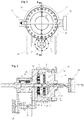
fig. 1 shows a front view of the filter for plastic material that is the object of the invention; -
fig. 2 shows the cross-section of the object offig. 1 along the section line AA; - fi. 3 shows a top view of the
device 1 with the hollow body in section; -
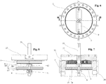
fig. 4 shows a perspective view of the hollow body according without a front cover, revealing the first filtering device and its scraper; -
fig. 5 shows what is set out infig. 4 , with the hollow body removed, to highlight the presence of two the filtration devices and relative scrapers; -
fig. 6 shows what is set out above infig. 4 from a front plan view; -
fig. 7 shows the object offig. 6 sectioned along the section line B-B: -
fig. 8 shows a side view of the object offig. 5 ; -
figs. 9, 10 and 11 respectively show two different side views and a sectional view along the section line C-C of the drive shaft with the two scrapers fitted; -
fig. 12 shows a second exploded perspective view of the drive shaft and the two scrapers; -
fig. 13 shows only a front plan view of one scraper; -
fig. 14 shows a section along a vertical plane passing through the main axis of the hollow body, fitted with the filtration devices arranged in series, each provided with its own ring with key. - With reference to the figures, the
filtration device 1 is basically composed of ahollow body 2 within which are housed afirst filtration device 3 and a second filtration device 4. - Said first and said
second filtration devices 3, 4, are arranged in sequence with a different filtration quality, so that thefirst filtering device 3, positioned upstream of the second filtration device 4 retains the largest pieces of dirt that in the molten plastic material, while the filtration device 4, which is downstream, retains the smallest dirt particles in the molten plastic material to be filtered. Each of saidfilter devices 3 and 4 is composed of aperforated disc hollow body 2. - Said
perforated disc hollow body 2 when operating. - Overlying and resting on a base of each of these
perforated discs perforated sheet perforated sheet hollow body 2, and for this reason rests on theperforated disc - On each of these
perforated sheets 7, 8 a significant amount of material accumulates during the filtration that gradually clog the various holes and reduces the amount of molten material can be effectively filtered. - For this reason there is, on each
perforated sheet scraper scraper scraping edge perforated sheet drive shaft 25.Said scraper perforated sheet - Each
perforated sheet edge perforated sheet radial support 25 connected solidly to thedrive shaft 25. Advantageously, eachscraper scraper sheets - This radial support has, for the entire or a large part of its longitudinal extension, in addition to the fastening of the
scraping sheet channel scraping blade collection channel - There is a
window scrapers drive shaft 25, in connection with and continuing thecollection channel windows hollow body 2. - Preferably the outflow of the dirt collected by the
first filtration device 3 occurs through thefront cover 26 of thehollow body 2, while the outflow of the dirt collected by the second filtration device 4 occurs on the bottom 27 of thehollow body 2, through thecentral cavity 24 of thedrive shaft 25. - In fact, said
drive shaft 25 is hollow in the centre and has anopening 23 at thesecond window 22 relative to the collectingchannel 16 of the radial support; while thefirst window 21 for the release of dirty material i connected to itsown pipe 17 discharging towards the outside of thehollow body 2. - Clearly, these
discharge pipes valves - It is conceivable, with particularly dirty material, that there is also a continuous rotation of the scrapers (3, 4).
- Said
valves actuators hollow body 2 in order to facilitate their maintenance. - The operation of the
filtration device 1 consists of a continuous flow of material entering through aninlet opening 34 of thehollow body 2 upstream of thefirst filtration device 3, into thefirst chamber 30 between the openingcover 26 and the firstperforated sheet 7. - The molten material passes through the
first filtering device 3, where the larger dirt particles are retained, to then pass through the holes of the corresponding firstperforated support disc 5 of the firstperforated sheet 7, within thesecond chamber 31, defined and included between the rear part of the firstperforated disc 5 and the secondperforated filtration sheet 8 of the second filtration device 4. - Because of the pressure of the incoming molten material, this molten material, in the
second chamber 31, is forced to move through the secondperforated sheet 8, which prevents the passage of the finer impurities, and subsequently, through the holes of the secondperforated disc 6, reaching afinal collector 32 to the rear of the secondperforated disc 6, connected with anoutlet opening 33, which runs through thehollow body 2 to the outside. - Even if there is a cleaning operation with lifting of the dirt by means of a
scraper hollow body 2 remains unchanged, or with a reduced flow. - This input of the material provides sufficient pressure because the dirty material, lifted by the
relative scraper blades same drive shaft 25, scraping in a rotary manner the respectiveperforated sheets relative channels various outlet pipes plastic material 1. - Indeed, the exit of the dirty product will only happen if the
respective valve respective actuator - It is evident that this actuator and respective valves can also be different from one another, for example pneumatic or hydraulic or with a different structure, such as a screw feeder.
- If, during the movement of the
scrapers valves respective channel scraper - The maintenance of the
filtration device 1 is equally simple. - Just open the
opening cover 26, on the front of thehollow body 2, extract thefirst scraper 9 that holds one or twoscraper blades 11; after that theperforated plate 7 and itsperforated disc 5 can be removed. - After removing the
first scraper 9 and thefirst filtering device 3, you can access thesecond scraper 10 and the second filtration device 4, to eventually remove the various parts for maintenance and/or cleaning.
Claims (10)
- Apparatus for filtration of plastic material composed of a hollow body (2) inside which are the filtration devices (3, 4) and on which are made to rotate, by means of an externally actuated drive shaft (25), scrapers (9, 10), where said hollow body (2) is equipped with at least an inlet opening (34) upstream of the filtration devices (3, 4) for the entry of molten material to be filtered and at least an outlet opening (33) downstream of the filtration devices (3, 4) for the exit of the filtered molten material, characterised by the fact that there
are at least two of said filtration devices (3, 4) arranged in series, in such a way that the material filtered by the first filtration device (3) meets the inlet of the second filtration device (4), and where said scrapers (9, 10) of both the first filtration device (3) and the second filtration device (4) are made to rotate by the same drive shaft (25). - Apparatus for filtration of plastic material according to claim 1, characterised by the fact that each of said filtration devices (3, 4) is composed of a perforated disc (5, 6) solidly connected to the hollow body (2), on which front surface,
based on the direction of the flow of the molten material, there is a perforated sheet (7, 8), with hole diameters for letting through the molten material, and between them at least two filtration devices (3, 4), so that the larger grain size extraneous elements are stopped on the first filtration device (3). - Apparatus for filtration of plastic material according to claim 1, characterised by the fact that the drive shaft (25) rotates the scrapers (9, 10) after at least a variation in pressure of the molten material along its path inside the filtration device (1).
- Apparatus for filtration of plastic material according to claim 1, characterised by the fact that said drive shaft (25) is central, and for at least one of its sections, hollow, where said cavity (24) is a discharge pipe (18) for taking away the dirty material picked up by a filtration device by a scraper inside the hollow body (2) on the outside of the filter for plastic material (1).
- Apparatus for filtration of plastic material according to the previous claim, characterised by the fact that said cavity (24) of the drive shaft (25) communicates with a first radial window (23), through which said dirty material enters, flowing through the cavity (24) of said drive shaft (25).
- Apparatus for filtration of plastic material according to claim 1, characterised by the fact that said cavity of the drive shaft (25) communicates with a second radial window (35), through which said dirty material flows out, flowing through the cavity (24) of said drive shaft, on the outside of the filtration device (1).
- Apparatus for filtration of plastic material according to claim 1, characterised by the fact that said scrapers (3, 4) consist of at least a support element that supports in an overhanging way a scraping sheet (11, 12), arranged in an oblique manner with respect to said filtration element (3, 4), and with the scraping edge (13, 14) resting on said filtration device (3, 4), where said support is configured for all or a good part of the extension with these the scraping sheets, with an open collection channel (15, 16) arranged along the support side of said scraping sheet (11, 12), in this way being able, during the movement of these sheets, to be rotated by the drive shaft (25), said channels convey the dirty material to the discharge pipes (17, 18).
- Apparatus for filtration of plastic material according to claim 4 or 5, characterised by the fact that said cavity (24) is joined to said discharge pipes (17, 18).
- Apparatus for filtration of plastic material according to claim 1 or 7, characterised by the fact that the dirty material collected by the first filtration device (3) and picked up by said scraper inside said collection channel (15) is made to flow through a discharge pipe (17) that passes through a cover (26) that closes the hollow body (2).
- Apparatus for filtration of plastic material according to claims 4 to 9, characterised by the fact that each of said discharge pipes (17, 18) has its own valve (19, 20) operated by its own actuators (28, 29) for opening and closing by command, to release the dirty material outside the hollow body (2).
Priority Applications (1)
| Application Number | Priority Date | Filing Date | Title |
|---|---|---|---|
| PL16167627T PL3088157T3 (en) | 2015-04-30 | 2016-04-29 | Filter for plastic material |
Applications Claiming Priority (1)
| Application Number | Priority Date | Filing Date | Title |
|---|---|---|---|
| ITUB20150321 | 2015-04-30 |
Publications (3)
| Publication Number | Publication Date |
|---|---|
| EP3088157A2 EP3088157A2 (en) | 2016-11-02 |
| EP3088157A3 EP3088157A3 (en) | 2016-11-09 |
| EP3088157B1 true EP3088157B1 (en) | 2021-05-12 |
Family
ID=53836677
Family Applications (1)
| Application Number | Title | Priority Date | Filing Date |
|---|---|---|---|
| EP16167627.5A Active EP3088157B1 (en) | 2015-04-30 | 2016-04-29 | Filter for plastic material |
Country Status (4)
| Country | Link |
|---|---|
| US (1) | US11103812B2 (en) |
| EP (1) | EP3088157B1 (en) |
| ES (1) | ES2885599T3 (en) |
| PL (1) | PL3088157T3 (en) |
Families Citing this family (18)
| Publication number | Priority date | Publication date | Assignee | Title |
|---|---|---|---|---|
| EP3088157B1 (en) * | 2015-04-30 | 2021-05-12 | Fimic S.r.l. | Filter for plastic material |
| CN107310072B (en) * | 2017-08-07 | 2018-11-09 | 江苏旺科新材料有限公司 | The shuttle-type filter plant of molten state waste plastic, foam |
| IT201800002341U1 (en) * | 2018-04-11 | 2019-10-11 | SELF-CLEANING AUTOMATIC FILTER FOR PLASTIC MATERIALS | |
| US11260570B2 (en) * | 2018-05-07 | 2022-03-01 | PSI-Polymer Systems, Inc. | Filtration apparatuses and screen changer devices for polymer processing and related methods |
| CN111225728B (en) * | 2018-05-15 | 2022-04-05 | 株式会社荒井铁工所 | Shearing member and filtering device |
| US11911719B2 (en) * | 2019-09-20 | 2024-02-27 | Massachusetts Institute Of Technology | Devices and methods for the integrated filtration, drying, and mechanical processing of active pharmaceutical ingredients |
| DE102020205462A1 (en) | 2020-04-30 | 2021-11-04 | Benecke-Kaliko Aktiengesellschaft | Grained film with recycled material for processing in deep-drawing processes |
| WO2021229111A1 (en) | 2020-05-12 | 2021-11-18 | Laboratorios Farmacéuticos Rovi, S.A. | Method for purifying biodegradable thermoplastic polymer particles for medical and/or pharmaceutical use |
| IT202000018892A1 (en) * | 2020-07-31 | 2022-01-31 | Break Polymer S R L | OPENING SYSTEM OF A FILTRATION DEVICE FOR PLASTIC MATERIALS, IN PARTICULAR OF A FILTRATION DEVICE USED IN PLASTIC MATERIAL RECYCLING PROCESSES |
| CN112023504A (en) * | 2020-09-04 | 2020-12-04 | 江苏隆达超合金航材有限公司 | Chute and filter screen combined device in casting high-temperature alloy smelting process |
| DE102020212184A1 (en) | 2020-09-28 | 2022-03-31 | Benecke-Kaliko Aktiengesellschaft | Facilitates recyclable and replaceable seat covers for mobility applications |
| AT524784B1 (en) * | 2021-04-07 | 2022-09-15 | Engel Austria Gmbh | Plasticizing unit for a shaping machine and method for operating one |
| CN113290739A (en) * | 2021-05-24 | 2021-08-24 | 李志新 | Degradable plastic and preparation method thereof |
| WO2023012682A1 (en) * | 2021-08-06 | 2023-02-09 | Break Polymer Srl | Filtering device for plastic materials equipped with opening system |
| CN117858790A (en) * | 2021-08-06 | 2024-04-09 | 破碎机械有限公司 | Filter device for plastic materials with a cleaning system |
| DE102021211290A1 (en) | 2021-09-13 | 2023-03-16 | Benecke-Kaliko Aktiengesellschaft | Grained film with recyclate for processing in deep-drawing processes |
| CN113797628A (en) * | 2021-09-30 | 2021-12-17 | 尚勇刚 | Traditional chinese medicine dregs of a decoction extrusion filter equipment |
| CN116510395B (en) * | 2023-05-22 | 2023-11-10 | 湖南展卓新材料科技有限公司 | Foreign matter cleaning device in copper liquid |
Family Cites Families (104)
| Publication number | Priority date | Publication date | Assignee | Title |
|---|---|---|---|---|
| US683386A (en) * | 1900-12-17 | 1901-09-24 | William Edward Corlett | Filter. |
| US925040A (en) * | 1908-05-23 | 1909-06-15 | Perley L Sennott | Straining-pail. |
| US1585817A (en) * | 1925-07-01 | 1926-05-25 | Bailey Frank | Apparatus for straining fluids |
| US1891396A (en) * | 1930-03-03 | 1932-12-20 | Paul W Prutzman | Filter press |
| US1956720A (en) * | 1931-02-20 | 1934-05-01 | Farrel Birmingham Co Inc | Strainer |
| US2107040A (en) * | 1935-01-26 | 1938-02-01 | Frank B Lomax | Process of filtering eggs |
| US2089702A (en) * | 1935-01-26 | 1937-08-10 | Frank B Lomax | Apparatus for filtering eggs |
| US2236769A (en) * | 1938-01-13 | 1941-04-01 | Armbruster Max | Apparatus for purifying liquid lubricants |
| NL132958C (en) * | 1945-04-07 | 1900-01-01 | ||
| US2480119A (en) * | 1946-02-25 | 1949-08-30 | Hervey G Cram | Disk pulp screen |
| US2682811A (en) * | 1952-09-23 | 1954-07-06 | Cowles Co | Machine for screening paper stock |
| US2728943A (en) * | 1953-09-29 | 1956-01-03 | Celanese Corp | Extrusion apparatus |
| GB759079A (en) * | 1953-12-11 | 1956-10-10 | Firestone Tire & Rubber Co | Improvements in or relating to extruders for making tubes |
| US3214019A (en) * | 1960-10-21 | 1965-10-26 | Bass Brothers Entpr Inc | Overload controlled drilling mud treatment system |
| US3146494A (en) * | 1961-11-13 | 1964-09-01 | Nat Rubber Machinery Co | Extruder with reverse flow flushed breaker plate assembly |
| BE626361A (en) * | 1961-12-26 | 1900-01-01 | ||
| US3243849A (en) * | 1964-05-19 | 1966-04-05 | Du Pont | Screen changing |
| US3361263A (en) * | 1965-06-10 | 1968-01-02 | Frank W Egan & Company | Automatic screening head for extruders |
| DE1302285B (en) * | 1965-07-07 | 1900-01-01 | United States Atomic Energy Commission | |
| US3455357A (en) * | 1967-02-03 | 1969-07-15 | Beringer Co Inc C J | Screen changer apparatus for extrusion machines |
| US3637191A (en) * | 1967-03-29 | 1972-01-25 | Sherwin Williams Co | Foundry mold and core blowing machine |
| CA989321A (en) * | 1970-07-17 | 1976-05-18 | Pcl Industries Limited | Method and aparatus for filtering flowable material |
| US3640395A (en) * | 1970-09-14 | 1972-02-08 | Kinney Eng Inc S P | Automatic self-cleaning strainer |
| US3767056A (en) * | 1971-08-06 | 1973-10-23 | A 1 Eng | Injection molding filter |
| US4010391A (en) * | 1972-04-19 | 1977-03-01 | Peter Gabor Kalman | Method of using multiple stressed sealing plugs to filter polymeric material |
| US3940335A (en) * | 1972-08-29 | 1976-02-24 | Peter Gabor Kalman | Filtering process and apparatus |
| US3856680A (en) * | 1973-10-15 | 1974-12-24 | Mobil Oil Corp | Automatic screen changer for extruding processes |
| JPS50151848U (en) * | 1974-06-04 | 1975-12-17 | ||
| DD114239A1 (en) * | 1974-08-19 | 1975-07-20 | ||
| JPS5196857A (en) * | 1975-02-20 | 1976-08-25 | Oshidashikino jidoromokokansochi | |
| US4076681A (en) * | 1976-08-19 | 1978-02-28 | Gulf Oil Corporation | Process for dissolving high molecular weight olefin polymers in liquid hydrocarbons |
| JPS53112962A (en) * | 1977-03-15 | 1978-10-02 | Tomoo Kinoshita | Wireenet replacement device of plastic filter |
| US4177234A (en) * | 1977-10-05 | 1979-12-04 | Metals & Plastics, Inc. | Method and apparatus for cleaning thermoplastic materials |
| JPS5927698B2 (en) * | 1977-11-28 | 1984-07-07 | 株式会社日本製鋼所 | Automatic "filter" mesh exchange device in plastic extrusion machine |
| US4162975A (en) * | 1978-02-07 | 1979-07-31 | Permutit Company, Inc. | High velocity composite strainer |
| US4280907A (en) * | 1979-08-14 | 1981-07-28 | Haeberle Wilhelm | Separating device |
| US4299707A (en) * | 1980-04-07 | 1981-11-10 | A-1 Engineering, Inc. | Apparatus for filtering melted plastic |
| US4470904A (en) * | 1981-10-28 | 1984-09-11 | Josef Gail | Mechanism for separating materials of varying consistency |
| US4430214A (en) * | 1982-09-15 | 1984-02-07 | Baker Marvin E | Strainer mill for swimming pool pump intake |
| US4511472A (en) * | 1983-03-30 | 1985-04-16 | Beringer Co., Inc. | Apparatus for continuous polymer filtration |
| JPS61174489A (en) * | 1985-01-28 | 1986-08-06 | 株式会社 サトミ製作所 | High concentration pulp screen |
| US4701118A (en) * | 1985-07-03 | 1987-10-20 | Kreyenborg Verwaltungen Und Beteiligungen Kg | Apparatus for filtering plasticized materials in extruders |
| DE3670006D1 (en) * | 1986-06-06 | 1990-05-10 | Erema | Filter. |
| US4755290A (en) * | 1986-11-13 | 1988-07-05 | Neuman Clayton L | Apparatus for continuously filtering plastic melt with noninterruptive purge |
| US4888110A (en) * | 1987-03-16 | 1989-12-19 | Key Filters, Inc. | Filtering device for thermoplastic material |
| US4921607A (en) * | 1988-02-25 | 1990-05-01 | Hoeganaes Corporation | Filter assembly for molten polymeric material |
| US4849113A (en) * | 1988-05-23 | 1989-07-18 | Hills William H | Continuous polymer filter |
| DE3840904C1 (en) * | 1988-12-05 | 1989-10-05 | Kreyenborg Verwaltungen Und Beteiligungen Kg, 4400 Muenster, De | |
| DE3902061A1 (en) * | 1989-01-25 | 1990-07-26 | Gneuss Kunststofftechnik Gmbh | SCREEN DEVICE FOR CLEANING PLASTIC MELTS |
| US5061170A (en) * | 1989-12-08 | 1991-10-29 | Exxon Chemical Patents Inc. | Apparatus for delivering molten polymer to an extrusion |
| DE3941831C1 (en) * | 1989-12-19 | 1990-10-18 | Kreyenborg Verwaltungen Und Beteiligungen Kg, 4400 Muenster, De | |
| DE4012404C1 (en) * | 1990-04-19 | 1991-02-28 | Kreyenborg Verwaltungen Und Beteiligungen Kg, 4400 Muenster, De | |
| US5078275A (en) * | 1990-11-13 | 1992-01-07 | The Black Clawson Company | Screening apparatus for paper making stock |
| US5200077A (en) * | 1991-04-08 | 1993-04-06 | Memtec America Corporation | Backflushable rotary melt polymer filter apparatus |
| US5141631A (en) * | 1991-06-07 | 1992-08-25 | John Brown Inc. | Polymer filter with backflush pump |
| AT400128B (en) * | 1992-02-14 | 1995-10-25 | Erema | FILTRATION DEVICE FOR FLOWABLE MATERIAL, ESPECIALLY FOR POLLUTED PLASTIC MELTS |
| TW287981B (en) * | 1993-02-04 | 1996-10-11 | Bacher Helmut | |
| US5482216A (en) * | 1993-04-21 | 1996-01-09 | Alfa Loop Inc. | Method for reclaiming plastic which contains undesirable contaminants |
| DE4325514C1 (en) * | 1993-07-29 | 1994-10-27 | Schaaf Technologie Gmbh | Cooking extruders for the production of thermally treated biopolymers and processes for cooking extrusion of biopolymers |
| DE4338129A1 (en) * | 1993-11-08 | 1995-05-11 | Zimmer Ag | Process for polymer melt filtration |
| SE9400335D0 (en) * | 1994-02-02 | 1994-02-02 | Astra Ab | Powder mixing |
| US5462653A (en) * | 1994-02-15 | 1995-10-31 | Hills, Inc. | Apparatus for continuous polymer filtration |
| ATE177678T1 (en) * | 1994-05-03 | 1999-04-15 | Kreyenborg Verwaltungen | FILTER DEVICE FOR EXTRUSION PRESSES |
| IT1267758B1 (en) * | 1994-06-28 | 1997-02-07 | Alba Bruno Dall | FILTRATION DEVICE FOR THE SEPARATION OF POLLUTING MATERIALS FROM PLASTIC MASSES MELTED IN PRESSES FOR THE EXTRUSION OF MATERIALS |
| DE19636067A1 (en) * | 1995-09-18 | 1997-03-20 | Barmag Barmer Maschf | Filtering of plastic melt and filtering equipment for reducing flow variation |
| US5688402A (en) * | 1995-12-15 | 1997-11-18 | General Electric Company | Self-cleaning strainer |
| US5658459A (en) * | 1995-12-29 | 1997-08-19 | Unites States Filter Corporation | Dual velocity strainer |
| AT403779B (en) * | 1996-01-22 | 1998-05-25 | Bacher Helmut | DEVICE FOR FILTERING PLASTIFIED THERMOPLASTIC PLASTICS AND FILTER ELEMENT FOR SUCH A DEVICE |
| DE19618090A1 (en) * | 1996-05-06 | 1997-11-13 | Hoechst Diafoil Gmbh | Filter device for evenly filtering plastic melts |
| US5618423A (en) * | 1996-07-23 | 1997-04-08 | Lin; Ping Ho | On-the-fly long-running rotary filtration screen device |
| AT404562B (en) * | 1996-12-05 | 1998-12-28 | Bacher Helmut | FILTER DEVICE FOR IMPURITIES OF LIQUIDS |
| DE19704621A1 (en) * | 1997-01-14 | 1998-09-24 | Josef Gail | Device for cleaning viscous material |
| CA2205450C (en) * | 1997-05-14 | 2001-07-24 | Alfredo Bentivoglio | Filter screen pack for extrusion die |
| IT1301853B1 (en) * | 1998-07-24 | 2000-07-07 | Previero Sas | NET ADVANCE DEVICE FOR FILTERING GROUP OF PLASTIC MATERIAL WITH CONTINUOUS FILTERING NET |
| IT1301946B1 (en) * | 1998-07-28 | 2000-07-20 | Previero Sas | FILTRATION GROUP FOR MELTED PLASTIC MATERIAL WITH REPLACEABLE FILTERING ELEMENTS WITHOUT STOPPING THE FLOW OF MATERIAL. |
| JP3548888B2 (en) * | 1998-09-17 | 2004-07-28 | 株式会社石垣 | Continuous compression dewatering equipment |
| US6168411B1 (en) * | 1999-03-18 | 2001-01-02 | Dynisco Extrusion, Inc. | Polymer filtration method and apparatus |
| US6117338A (en) * | 1999-03-25 | 2000-09-12 | Solutia, Inc. | Continuous polymer melt filtration |
| DE29908735U1 (en) * | 1999-05-18 | 1999-09-02 | Kosa Gmbh & Co Kg | Filter device for cleaning plastic melts |
| US6290483B1 (en) * | 1999-10-06 | 2001-09-18 | Robert Reiser & Co., Inc. | Apparatus for food extrusion |
| DE10229406A1 (en) * | 2002-06-29 | 2004-01-22 | Ettlinger Kunststoffmaschinen Gmbh | Device for the continuous filtering of material mixtures |
| US20060219645A1 (en) * | 2003-05-15 | 2006-10-05 | Continuum Dynamics, Inc. | Self-cleaning strainer |
| DE20319752U1 (en) * | 2003-12-20 | 2005-05-12 | Ettlinger Kunststoffmaschinen Gmbh | Device for continuous filtering of material mixtures |
| EP1761318B1 (en) * | 2004-05-23 | 2007-12-05 | Rosenmund VTA AG | Method and device for removal of residual products |
| EP1807186B1 (en) * | 2004-09-15 | 2012-08-22 | Kureha Corporation | Apparatus and method for solid-liquid contact |
| DE102004054687B3 (en) * | 2004-11-12 | 2006-06-14 | Zimmer Ag | Reactor for the treatment of highly viscous plastic melts |
| AT503788B1 (en) * | 2006-09-13 | 2008-01-15 | Schulz Helmuth Ing | Device for continuous filtration of impurities from plastic melt, comprises a filter insert in the form of hollow rotating body mounted about its axis of rotation with respect to housing, and a discharge device having transport screw |
| US8057685B2 (en) * | 2008-06-11 | 2011-11-15 | James Benson, III | Solid separator |
| DE102010055167A1 (en) * | 2010-12-18 | 2012-06-21 | Ettlinger Kunststoffmaschinen Gmbh | Device for continuous filtering of material mixtures |
| DE102012100641A1 (en) * | 2011-07-29 | 2013-01-31 | Kreyenborg Verwaltungen Und Beteiligungen Gmbh & Co. Kg | Filter apparatus for large surface filtration of e.g. polyamide, has filter insert pushed into opening by displacement of support element, and closure element inserted into housing bore or at opening of bore when lowering support element |
| US9561454B2 (en) * | 2012-10-09 | 2017-02-07 | Ovivo Inc. | Debris filter with splitter bar |
| US20140224749A1 (en) * | 2013-02-12 | 2014-08-14 | Sam Arthur Hopkins | Filter Mesh Assembly for a Plastic Extruder Filter Assembly |
| AT514439B1 (en) * | 2013-10-04 | 2015-01-15 | Erema | filter means |
| AT514436B1 (en) * | 2013-10-04 | 2015-01-15 | Erema | filter means |
| CN103692636B (en) * | 2013-11-12 | 2015-12-09 | 张家港市紫东机械科技有限公司 | A kind of without wire gauzee filter |
| CN204136398U (en) * | 2014-11-07 | 2015-02-04 | 浙江乐能科技有限公司 | Without wire gauzee filter |
| CN204235866U (en) * | 2014-11-24 | 2015-04-01 | 浙江乐能科技有限公司 | A kind of novel without wire gauzee filter |
| DE102015226348A1 (en) * | 2015-12-21 | 2017-06-22 | Next Generation Analytics Gmbh | band filter |
| US10807295B2 (en) * | 2015-02-19 | 2020-10-20 | Next Generation Analytics Gmbh | Filter device and filter method |
| EP3088157B1 (en) * | 2015-04-30 | 2021-05-12 | Fimic S.r.l. | Filter for plastic material |
| DE202016103608U1 (en) * | 2016-07-06 | 2016-08-22 | Nordson Corporation | Filter device and cleaning device for removing dirt particles from a filter element of a filter device Filter device and cleaning device for removing dirt particles from a filter element of a filter device |
| EP3308940A1 (en) * | 2016-10-17 | 2018-04-18 | Next Generation Analytics GmbH | Filtering system for viscose or highly viscose liquids, in particular molten plastic and method for filtering viscose or highly-viscose liquids |
| IT201800002341U1 (en) * | 2018-04-11 | 2019-10-11 | SELF-CLEANING AUTOMATIC FILTER FOR PLASTIC MATERIALS | |
| DE202019102066U1 (en) * | 2019-04-10 | 2019-05-02 | Fimic S.R.L. | Automatic self-cleaning filter for plastics |
-
2016
- 2016-04-29 EP EP16167627.5A patent/EP3088157B1/en active Active
- 2016-04-29 ES ES16167627T patent/ES2885599T3/en active Active
- 2016-04-29 PL PL16167627T patent/PL3088157T3/en unknown
- 2016-04-30 US US15/143,527 patent/US11103812B2/en active Active
Non-Patent Citations (1)
| Title |
|---|
| None * |
Also Published As
| Publication number | Publication date |
|---|---|
| EP3088157A3 (en) | 2016-11-09 |
| US20160317953A1 (en) | 2016-11-03 |
| PL3088157T3 (en) | 2021-11-08 |
| US11103812B2 (en) | 2021-08-31 |
| EP3088157A2 (en) | 2016-11-02 |
| ES2885599T3 (en) | 2021-12-14 |
Similar Documents
| Publication | Publication Date | Title |
|---|---|---|
| EP3088157B1 (en) | Filter for plastic material | |
| US4973406A (en) | Device for the separation of particulated solids from a pressurized fluid | |
| JP6294833B2 (en) | Filter device for filtering fluid over a large area | |
| MXPA00004843A (en) | Filter device for cleaning plastics melts. | |
| KR101935995B1 (en) | Melt extruder of synthetic resin | |
| CN104096396B (en) | A kind of filter | |
| CA2278861C (en) | Filter device for flowable plastic material | |
| EP2602087B1 (en) | Apparatus and process for filtering plastic materials | |
| CN107379489B (en) | Center deslagging type non-screen-change non-fluctuation filter | |
| EP0452654A2 (en) | Installation for purifying a metal melting bath with ceramic filter | |
| KR101594678B1 (en) | Prevent clogging of filter plate device for melt extruder of synthetic resin | |
| WO2008104863A2 (en) | A device and a process for cleaning filters for plastic materials | |
| CN210841481U (en) | Red date concentrated juice purification device | |
| KR200184038Y1 (en) | Impurities exclusion equipment of extruding machine | |
| CN209809666U (en) | Vertical back flush filter | |
| RU2528721C1 (en) | Device for filtration of food liquids, mainly, milk | |
| CN219050502U (en) | Filter is retrieved to filter residue | |
| US3043434A (en) | Filtration apparatus | |
| EP4129439A1 (en) | A filtering device and a distribution line for distributing a fluid having solid particles in suspension | |
| KR20140062760A (en) | Sieve and device for separate solids from liquids | |
| KR100999457B1 (en) | Apparatus for screening plastic waste | |
| CN219325511U (en) | Self-cleaning two-stage plastic melt filter | |
| CN220846358U (en) | Melt filter | |
| IT201800002341U1 (en) | SELF-CLEANING AUTOMATIC FILTER FOR PLASTIC MATERIALS | |
| CN115321570B (en) | Distillation type cryolite production is with refining device based on bioengineering |
Legal Events
| Date | Code | Title | Description |
|---|---|---|---|
| PUAI | Public reference made under article 153(3) epc to a published international application that has entered the european phase |
Free format text: ORIGINAL CODE: 0009012 |
|
| PUAL | Search report despatched |
Free format text: ORIGINAL CODE: 0009013 |
|
| AK | Designated contracting states |
Kind code of ref document: A2 Designated state(s): AL AT BE BG CH CY CZ DE DK EE ES FI FR GB GR HR HU IE IS IT LI LT LU LV MC MK MT NL NO PL PT RO RS SE SI SK SM TR |
|
| AX | Request for extension of the european patent |
Extension state: BA ME |
|
| AK | Designated contracting states |
Kind code of ref document: A3 Designated state(s): AL AT BE BG CH CY CZ DE DK EE ES FI FR GB GR HR HU IE IS IT LI LT LU LV MC MK MT NL NO PL PT RO RS SE SI SK SM TR |
|
| AX | Request for extension of the european patent |
Extension state: BA ME |
|
| RIC1 | Information provided on ipc code assigned before grant |
Ipc: B29C 47/68 20060101ALI20160930BHEP Ipc: B29C 47/08 20060101AFI20160930BHEP Ipc: B29C 47/92 20060101ALN20160930BHEP |
|
| STAA | Information on the status of an ep patent application or granted ep patent |
Free format text: STATUS: REQUEST FOR EXAMINATION WAS MADE |
|
| 17P | Request for examination filed |
Effective date: 20170328 |
|
| RBV | Designated contracting states (corrected) |
Designated state(s): AL AT BE BG CH CY CZ DE DK EE ES FI FR GB GR HR HU IE IS IT LI LT LU LV MC MK MT NL NO PL PT RO RS SE SI SK SM TR |
|
| STAA | Information on the status of an ep patent application or granted ep patent |
Free format text: STATUS: EXAMINATION IS IN PROGRESS |
|
| 17Q | First examination report despatched |
Effective date: 20200623 |
|
| STAA | Information on the status of an ep patent application or granted ep patent |
Free format text: STATUS: EXAMINATION IS IN PROGRESS |
|
| REG | Reference to a national code |
Ref country code: DE Ref legal event code: R079 Ref document number: 602016057678 Country of ref document: DE Free format text: PREVIOUS MAIN CLASS: B29C0047080000 Ipc: B29C0048080000 |
|
| RIC1 | Information provided on ipc code assigned before grant |
Ipc: B29C 48/08 20190101AFI20210114BHEP Ipc: B29C 48/68 20190101ALI20210114BHEP |
|
| GRAP | Despatch of communication of intention to grant a patent |
Free format text: ORIGINAL CODE: EPIDOSNIGR1 |
|
| STAA | Information on the status of an ep patent application or granted ep patent |
Free format text: STATUS: GRANT OF PATENT IS INTENDED |
|
| GRAS | Grant fee paid |
Free format text: ORIGINAL CODE: EPIDOSNIGR3 |
|
| INTG | Intention to grant announced |
Effective date: 20210310 |
|
| GRAA | (expected) grant |
Free format text: ORIGINAL CODE: 0009210 |
|
| STAA | Information on the status of an ep patent application or granted ep patent |
Free format text: STATUS: THE PATENT HAS BEEN GRANTED |
|
| AK | Designated contracting states |
Kind code of ref document: B1 Designated state(s): AL AT BE BG CH CY CZ DE DK EE ES FI FR GB GR HR HU IE IS IT LI LT LU LV MC MK MT NL NO PL PT RO RS SE SI SK SM TR |
|
| REG | Reference to a national code |
Ref country code: GB Ref legal event code: FG4D |
|
| REG | Reference to a national code |
Ref country code: CH Ref legal event code: EP |
|
| REG | Reference to a national code |
Ref country code: DE Ref legal event code: R096 Ref document number: 602016057678 Country of ref document: DE |
|
| REG | Reference to a national code |
Ref country code: IE Ref legal event code: FG4D |
|
| REG | Reference to a national code |
Ref country code: AT Ref legal event code: REF Ref document number: 1391892 Country of ref document: AT Kind code of ref document: T Effective date: 20210615 |
|
| REG | Reference to a national code |
Ref country code: NL Ref legal event code: FP |
|
| REG | Reference to a national code |
Ref country code: LT Ref legal event code: MG9D |
|
| PG25 | Lapsed in a contracting state [announced via postgrant information from national office to epo] |
Ref country code: BG Free format text: LAPSE BECAUSE OF FAILURE TO SUBMIT A TRANSLATION OF THE DESCRIPTION OR TO PAY THE FEE WITHIN THE PRESCRIBED TIME-LIMIT Effective date: 20210812 Ref country code: HR Free format text: LAPSE BECAUSE OF FAILURE TO SUBMIT A TRANSLATION OF THE DESCRIPTION OR TO PAY THE FEE WITHIN THE PRESCRIBED TIME-LIMIT Effective date: 20210512 Ref country code: LT Free format text: LAPSE BECAUSE OF FAILURE TO SUBMIT A TRANSLATION OF THE DESCRIPTION OR TO PAY THE FEE WITHIN THE PRESCRIBED TIME-LIMIT Effective date: 20210512 Ref country code: FI Free format text: LAPSE BECAUSE OF FAILURE TO SUBMIT A TRANSLATION OF THE DESCRIPTION OR TO PAY THE FEE WITHIN THE PRESCRIBED TIME-LIMIT Effective date: 20210512 |
|
| PG25 | Lapsed in a contracting state [announced via postgrant information from national office to epo] |
Ref country code: LV Free format text: LAPSE BECAUSE OF FAILURE TO SUBMIT A TRANSLATION OF THE DESCRIPTION OR TO PAY THE FEE WITHIN THE PRESCRIBED TIME-LIMIT Effective date: 20210512 Ref country code: GR Free format text: LAPSE BECAUSE OF FAILURE TO SUBMIT A TRANSLATION OF THE DESCRIPTION OR TO PAY THE FEE WITHIN THE PRESCRIBED TIME-LIMIT Effective date: 20210813 Ref country code: IS Free format text: LAPSE BECAUSE OF FAILURE TO SUBMIT A TRANSLATION OF THE DESCRIPTION OR TO PAY THE FEE WITHIN THE PRESCRIBED TIME-LIMIT Effective date: 20210912 Ref country code: RS Free format text: LAPSE BECAUSE OF FAILURE TO SUBMIT A TRANSLATION OF THE DESCRIPTION OR TO PAY THE FEE WITHIN THE PRESCRIBED TIME-LIMIT Effective date: 20210512 Ref country code: SE Free format text: LAPSE BECAUSE OF FAILURE TO SUBMIT A TRANSLATION OF THE DESCRIPTION OR TO PAY THE FEE WITHIN THE PRESCRIBED TIME-LIMIT Effective date: 20210512 Ref country code: PT Free format text: LAPSE BECAUSE OF FAILURE TO SUBMIT A TRANSLATION OF THE DESCRIPTION OR TO PAY THE FEE WITHIN THE PRESCRIBED TIME-LIMIT Effective date: 20210913 Ref country code: NO Free format text: LAPSE BECAUSE OF FAILURE TO SUBMIT A TRANSLATION OF THE DESCRIPTION OR TO PAY THE FEE WITHIN THE PRESCRIBED TIME-LIMIT Effective date: 20210812 |
|
| REG | Reference to a national code |
Ref country code: ES Ref legal event code: FG2A Ref document number: 2885599 Country of ref document: ES Kind code of ref document: T3 Effective date: 20211214 |
|
| PG25 | Lapsed in a contracting state [announced via postgrant information from national office to epo] |
Ref country code: RO Free format text: LAPSE BECAUSE OF FAILURE TO SUBMIT A TRANSLATION OF THE DESCRIPTION OR TO PAY THE FEE WITHIN THE PRESCRIBED TIME-LIMIT Effective date: 20210512 Ref country code: SM Free format text: LAPSE BECAUSE OF FAILURE TO SUBMIT A TRANSLATION OF THE DESCRIPTION OR TO PAY THE FEE WITHIN THE PRESCRIBED TIME-LIMIT Effective date: 20210512 Ref country code: SK Free format text: LAPSE BECAUSE OF FAILURE TO SUBMIT A TRANSLATION OF THE DESCRIPTION OR TO PAY THE FEE WITHIN THE PRESCRIBED TIME-LIMIT Effective date: 20210512 Ref country code: EE Free format text: LAPSE BECAUSE OF FAILURE TO SUBMIT A TRANSLATION OF THE DESCRIPTION OR TO PAY THE FEE WITHIN THE PRESCRIBED TIME-LIMIT Effective date: 20210512 Ref country code: DK Free format text: LAPSE BECAUSE OF FAILURE TO SUBMIT A TRANSLATION OF THE DESCRIPTION OR TO PAY THE FEE WITHIN THE PRESCRIBED TIME-LIMIT Effective date: 20210512 Ref country code: CZ Free format text: LAPSE BECAUSE OF FAILURE TO SUBMIT A TRANSLATION OF THE DESCRIPTION OR TO PAY THE FEE WITHIN THE PRESCRIBED TIME-LIMIT Effective date: 20210512 |
|
| REG | Reference to a national code |
Ref country code: DE Ref legal event code: R097 Ref document number: 602016057678 Country of ref document: DE |
|
| PLBE | No opposition filed within time limit |
Free format text: ORIGINAL CODE: 0009261 |
|
| STAA | Information on the status of an ep patent application or granted ep patent |
Free format text: STATUS: NO OPPOSITION FILED WITHIN TIME LIMIT |
|
| 26N | No opposition filed |
Effective date: 20220215 |
|
| PG25 | Lapsed in a contracting state [announced via postgrant information from national office to epo] |
Ref country code: IS Free format text: LAPSE BECAUSE OF FAILURE TO SUBMIT A TRANSLATION OF THE DESCRIPTION OR TO PAY THE FEE WITHIN THE PRESCRIBED TIME-LIMIT Effective date: 20210912 Ref country code: AL Free format text: LAPSE BECAUSE OF FAILURE TO SUBMIT A TRANSLATION OF THE DESCRIPTION OR TO PAY THE FEE WITHIN THE PRESCRIBED TIME-LIMIT Effective date: 20210512 |
|
| REG | Reference to a national code |
Ref country code: CH Ref legal event code: PL |
|
| GBPC | Gb: european patent ceased through non-payment of renewal fee |
Effective date: 20220429 |
|
| PG25 | Lapsed in a contracting state [announced via postgrant information from national office to epo] |
Ref country code: MC Free format text: LAPSE BECAUSE OF FAILURE TO SUBMIT A TRANSLATION OF THE DESCRIPTION OR TO PAY THE FEE WITHIN THE PRESCRIBED TIME-LIMIT Effective date: 20210512 Ref country code: LU Free format text: LAPSE BECAUSE OF NON-PAYMENT OF DUE FEES Effective date: 20220429 Ref country code: LI Free format text: LAPSE BECAUSE OF NON-PAYMENT OF DUE FEES Effective date: 20220430 Ref country code: GB Free format text: LAPSE BECAUSE OF NON-PAYMENT OF DUE FEES Effective date: 20220429 Ref country code: CH Free format text: LAPSE BECAUSE OF NON-PAYMENT OF DUE FEES Effective date: 20220430 |
|
| PGFP | Annual fee paid to national office [announced via postgrant information from national office to epo] |
Ref country code: NL Payment date: 20230224 Year of fee payment: 8 |
|
| PG25 | Lapsed in a contracting state [announced via postgrant information from national office to epo] |
Ref country code: IE Free format text: LAPSE BECAUSE OF NON-PAYMENT OF DUE FEES Effective date: 20220429 |
|
| PGFP | Annual fee paid to national office [announced via postgrant information from national office to epo] |
Ref country code: FR Payment date: 20230223 Year of fee payment: 8 |
|
| PGFP | Annual fee paid to national office [announced via postgrant information from national office to epo] |
Ref country code: TR Payment date: 20230301 Year of fee payment: 8 Ref country code: PL Payment date: 20230224 Year of fee payment: 8 Ref country code: IT Payment date: 20230223 Year of fee payment: 8 Ref country code: BE Payment date: 20230224 Year of fee payment: 8 |
|
| PGFP | Annual fee paid to national office [announced via postgrant information from national office to epo] |
Ref country code: ES Payment date: 20230525 Year of fee payment: 8 Ref country code: DE Payment date: 20230224 Year of fee payment: 8 |
|
| PGFP | Annual fee paid to national office [announced via postgrant information from national office to epo] |
Ref country code: AT Payment date: 20230224 Year of fee payment: 8 |
|
| PG25 | Lapsed in a contracting state [announced via postgrant information from national office to epo] |
Ref country code: HU Free format text: LAPSE BECAUSE OF FAILURE TO SUBMIT A TRANSLATION OF THE DESCRIPTION OR TO PAY THE FEE WITHIN THE PRESCRIBED TIME-LIMIT; INVALID AB INITIO Effective date: 20160429 |
|
| PGFP | Annual fee paid to national office [announced via postgrant information from national office to epo] |
Ref country code: NL Payment date: 20240318 Year of fee payment: 9 |