EP3088111A1 - Drill insert and indexable drill - Google Patents
Drill insert and indexable drill Download PDFInfo
- Publication number
- EP3088111A1 EP3088111A1 EP14873371.0A EP14873371A EP3088111A1 EP 3088111 A1 EP3088111 A1 EP 3088111A1 EP 14873371 A EP14873371 A EP 14873371A EP 3088111 A1 EP3088111 A1 EP 3088111A1
- Authority
- EP
- European Patent Office
- Prior art keywords
- face
- cutting blade
- drill
- convex curved
- insert
- Prior art date
- Legal status (The legal status is an assumption and is not a legal conclusion. Google has not performed a legal analysis and makes no representation as to the accuracy of the status listed.)
- Granted
Links
- 238000003466 welding Methods 0.000 abstract description 11
- 239000010935 stainless steel Substances 0.000 description 6
- 229910001220 stainless steel Inorganic materials 0.000 description 6
- 230000007423 decrease Effects 0.000 description 5
- 239000000463 material Substances 0.000 description 3
- 229910045601 alloy Inorganic materials 0.000 description 2
- 239000000956 alloy Substances 0.000 description 2
- 238000005553 drilling Methods 0.000 description 2
- 238000003754 machining Methods 0.000 description 2
- 230000000630 rising effect Effects 0.000 description 2
- 229910000831 Steel Inorganic materials 0.000 description 1
- 230000000694 effects Effects 0.000 description 1
- 239000007769 metal material Substances 0.000 description 1
- 230000000149 penetrating effect Effects 0.000 description 1
- 239000010959 steel Substances 0.000 description 1
- 230000007704 transition Effects 0.000 description 1
Images


Classifications
-
- B—PERFORMING OPERATIONS; TRANSPORTING
- B23—MACHINE TOOLS; METAL-WORKING NOT OTHERWISE PROVIDED FOR
- B23B—TURNING; BORING
- B23B51/00—Tools for drilling machines
- B23B51/02—Twist drills
-
- B—PERFORMING OPERATIONS; TRANSPORTING
- B23—MACHINE TOOLS; METAL-WORKING NOT OTHERWISE PROVIDED FOR
- B23B—TURNING; BORING
- B23B51/00—Tools for drilling machines
-
- B—PERFORMING OPERATIONS; TRANSPORTING
- B23—MACHINE TOOLS; METAL-WORKING NOT OTHERWISE PROVIDED FOR
- B23B—TURNING; BORING
- B23B27/00—Tools for turning or boring machines; Tools of a similar kind in general; Accessories therefor
- B23B27/14—Cutting tools of which the bits or tips or cutting inserts are of special material
- B23B27/16—Cutting tools of which the bits or tips or cutting inserts are of special material with exchangeable cutting bits or cutting inserts, e.g. able to be clamped
- B23B27/1662—Cutting tools of which the bits or tips or cutting inserts are of special material with exchangeable cutting bits or cutting inserts, e.g. able to be clamped with plate-like cutting inserts clamped against the walls of the recess in the shank by a clamping member acting upon the wall of a hole in the cutting insert
-
- B—PERFORMING OPERATIONS; TRANSPORTING
- B23—MACHINE TOOLS; METAL-WORKING NOT OTHERWISE PROVIDED FOR
- B23B—TURNING; BORING
- B23B27/00—Tools for turning or boring machines; Tools of a similar kind in general; Accessories therefor
- B23B27/14—Cutting tools of which the bits or tips or cutting inserts are of special material
- B23B27/16—Cutting tools of which the bits or tips or cutting inserts are of special material with exchangeable cutting bits or cutting inserts, e.g. able to be clamped
- B23B27/1614—Cutting tools of which the bits or tips or cutting inserts are of special material with exchangeable cutting bits or cutting inserts, e.g. able to be clamped with plate-like cutting inserts of special shape clamped against the walls of the recess in the shank by a clamping member acting upon the wall of a hole in the insert
- B23B27/1622—Cutting tools of which the bits or tips or cutting inserts are of special material with exchangeable cutting bits or cutting inserts, e.g. able to be clamped with plate-like cutting inserts of special shape clamped against the walls of the recess in the shank by a clamping member acting upon the wall of a hole in the insert characterised by having a special shape
-
- B—PERFORMING OPERATIONS; TRANSPORTING
- B23—MACHINE TOOLS; METAL-WORKING NOT OTHERWISE PROVIDED FOR
- B23B—TURNING; BORING
- B23B2200/00—Details of cutting inserts
- B23B2200/04—Overall shape
- B23B2200/0471—Square
- B23B2200/0476—Square rounded
-
- B—PERFORMING OPERATIONS; TRANSPORTING
- B23—MACHINE TOOLS; METAL-WORKING NOT OTHERWISE PROVIDED FOR
- B23B—TURNING; BORING
- B23B2200/00—Details of cutting inserts
- B23B2200/08—Rake or top surfaces
- B23B2200/083—Rake or top surfaces curved
-
- B—PERFORMING OPERATIONS; TRANSPORTING
- B23—MACHINE TOOLS; METAL-WORKING NOT OTHERWISE PROVIDED FOR
- B23B—TURNING; BORING
- B23B2200/00—Details of cutting inserts
- B23B2200/08—Rake or top surfaces
- B23B2200/085—Rake or top surfaces discontinuous
-
- B—PERFORMING OPERATIONS; TRANSPORTING
- B23—MACHINE TOOLS; METAL-WORKING NOT OTHERWISE PROVIDED FOR
- B23B—TURNING; BORING
- B23B2200/00—Details of cutting inserts
- B23B2200/08—Rake or top surfaces
- B23B2200/086—Rake or top surfaces with one or more grooves
- B23B2200/087—Rake or top surfaces with one or more grooves for chip breaking
-
- B—PERFORMING OPERATIONS; TRANSPORTING
- B23—MACHINE TOOLS; METAL-WORKING NOT OTHERWISE PROVIDED FOR
- B23B—TURNING; BORING
- B23B2200/00—Details of cutting inserts
- B23B2200/24—Cross section of the cutting edge
- B23B2200/242—Cross section of the cutting edge bevelled or chamfered
-
- B—PERFORMING OPERATIONS; TRANSPORTING
- B23—MACHINE TOOLS; METAL-WORKING NOT OTHERWISE PROVIDED FOR
- B23B—TURNING; BORING
- B23B2200/00—Details of cutting inserts
- B23B2200/24—Cross section of the cutting edge
- B23B2200/245—Cross section of the cutting edge rounded
-
- B—PERFORMING OPERATIONS; TRANSPORTING
- B23—MACHINE TOOLS; METAL-WORKING NOT OTHERWISE PROVIDED FOR
- B23B—TURNING; BORING
- B23B2251/00—Details of tools for drilling machines
- B23B2251/12—Cross sectional views of the cutting edges
- B23B2251/125—Rounded cutting edges
-
- B—PERFORMING OPERATIONS; TRANSPORTING
- B23—MACHINE TOOLS; METAL-WORKING NOT OTHERWISE PROVIDED FOR
- B23B—TURNING; BORING
- B23B2251/00—Details of tools for drilling machines
- B23B2251/50—Drilling tools comprising cutting inserts
Definitions
- the present invention relates to a drill insert which is detachably attached to a distal portion of a drill body of a cutting edge replacement type drill, and a cutting edge replacement type drill to which the drill insert is detachably attached.
- a drill insert is disclosed in PTL 1, in which cutting blades are formed on one pair of side ridge portions continuous with one apex of rake face forming a polygon of a polygonal flat plate-shaped insert body, an inner circumferential side chip breaker protrudes from the rake face continuous with one of the cutting blades, and an outer circumferential side chip breaker which is recessed from the rake face is formed on the other one of the cutting blades.
- the drill inserts having the same shape and the same size as each other are attached to the inner circumferential side and the outer circumferential side of the distal portion of a drill body, the cutting blade on which the inner circumferential side chip breaker is formed is used for drilling in the inner circumferential side drill insert, and the cutting blade on which the outer circumferential side chip breaker is formed is used for drilling in the outer circumferential side drill insert.
- PTL 2 discloses a drill insert, in which the drill insert, which is attached to the inner circumferential side of the distal portion of a drill body out of drill inserts attached to the inner circumferential side and the outer circumferential side of the distal portion of the drill body, is set to a central insert, and a rake angle of an operating edge (cutting blade) of the square central insert increases in a rotation axis of a drill in a region in which the inner circumferential drill insert and the outer circumferential drill insert overlap each other.
- a chamfered edge negative land is formed on the cutting blade on the rotation axis, and has a negative angle of approximately 15°.
- a circumferential speed by the rotation of the drill body decreases from the outer circumferential side of the drill body toward the inner circumferential side, and the circumferential speed and a cutting speed on the rotation axis of the drill body become zero. Accordingly, in the drill insert attached to the inner circumferential side of the drill body, particularly, the cutting blade cuts a workpiece while squeezing the workpiece in the vicinity of the rotation axis, and a cutting load or cutting resistance increases.
- the negative land having the negative angle is formed on the cutting blade on the rotation axis of the drill body, and a certain degree of strength of the cutting blade can be ensured.
- the breaker groove is formed on the rake face on the inner circumferential side of the drill body slightly separated from the rotation axis, and the rake angle has a positive angle within a range of 5° to 20°. Accordingly, similarly to the drill insert disclosed in PTL 1, it is difficult to ensure chipping resistance.
- a workpiece to be drilled is formed of stainless steel or the like, particularly, as described above, in the vicinity of the rotation axis of the drill body in which the cutting blade performs cutting while squeezing the workpiece, welding of scraps or chips easily occurs on the cutting edge of the cutting blade due to an increase of cutting heat according to the increase of the cutting resistance. Accordingly, when weld deposits are peeled due to the welding, the cutting blade may be damaged.
- the drill insert disclosed in PTL 2 if the negative land is formed on the cutting blade on the rotation axis of the drill body, since the cutting resistance increases and the cutting heat increases even though the strength of the cutting blade can be ensured, damage due to the welding easily occurs.
- the present invention is made in consideration of the above-described circumstances, and an object thereof is to provide a drill insert which is attached to the inner circumferential side of the distal portion of the drill body, particularly, can ensure sufficient chipping resistance with respect to a cutting load or cutting resistance, and can prevent damage due to the welding, and a cutting edge replacement type drill which is detachably attached to the drill insert.
- a drill insert which is detachably attached to a distal portion of a drill body which is rotated around an axis, in which a polygon face of a polygonal plate-shaped insert body is a rake face, a side face of the insert body disposed around the rake face is a flank face, and a cutting blade is formed on a ridge portion in which the rake face and the flank face intersect each other.
- the cutting blade includes a honing face which is formed on a first cutting blade portion continuous with at least one end portion of both end portions of the cutting blade and which gradually rises from the flank face toward the rake face, the honing face includes a first convex curved face continuous with the rake face and a second convex curved face continuous with the flank face, and in a cross section orthogonal to the cutting blade, a curvature radius of the first convex curved face is larger than a curvature radius of the second convex curved face.
- a cutting edge replacement type drill in which the drill insert configured as described above is detachably attached to a distal portion of a drill body which is rotated around an axis such that the cutting blade protrudes from the distal end of the drill body, the one end portion of the cutting blade is positioned in the vicinity of the axis and the other end portion of both end portions of the cutting blade is positioned on the outer circumferential side of the drill body when viewed from a rotation direction of the drill body, and the first cutting blade portion and the axis intersect each other.
- the first cutting blade portion on which a negative honing face gradually rising from the flank face of the cutting blade toward the rake face is formed, is positioned in the vicinity of the axis of the inner circumferential side of the drill body.
- a lip angle of the first cutting blade portion can increase and the honing face includes the first convex curved face continuous with the rake face and the second convex curved face continuous with the flank face, it is possible to ensure strength of the cutting blade in an intersection ridge portion between the honing face substantially functioning as the edge of the cutting blade and the flank face, by the second convex curved face, and it is possible to obtain sufficient chipping resistance with respect to a cutting load or cutting resistance.
- the first convex curved face which has the curvature radius larger than that of the second convex curved face and has an arc gentler than that of the second convex curved face, is formed on the rake face side of the honing face, and it is possible to decrease resistance when scraps or chips scratch. Accordingly, even though a workpiece is stainless steel or the like, it is possible to prevent occurrence of welding due to an increase of cutting heat in the first cutting blade portion positioned on the inner circumferential side of the drill body, and it is possible to prevent damage of the cutting blade due to the welding.
- the first cutting blade portion may have a length which is 1/2 or more of a length of the cutting blade. Accordingly, it is possible to reliably ensure the chipping resistance in a portion in which the cutting load or the cutting resistance increases in the vicinity of the axis when the drill insert is attached to the drill body. That is, if the length of the first cutting blade portion on which the honing face having the first and second convex curved faces is formed is less than 1/2 of the length of the cutting blade, there is a concern that it is not possible to reliably ensure the chipping resistance on the other end portion side of the cutting blade rather than the first cutting blade portion according to the applied cutting load or the cutting resistance.
- a breaker groove which has a bottom surface continuous with the honing face may be formed on the rake face, and the bottom surface of the breaker groove may be formed so as to be inclined to gradually retreat as the bottom surface is separated from the honing face. Accordingly, it is possible to prevent the cutting resistance from increasing more than is needed by the honing face rising in a negative shape.
- the entire length portion of the cutting blade may be the first cutting blade portion.
- a land which gradually retreats from the flank face side toward the rake face may be formed on a second cutting blade portion continuous with the other end portion of both end portions of the cutting blade, on the outer circumferential side of the drill body in which a cutting speed increases in the cutting blade protruding from the distal end of the drill body. Accordingly, it is possible to further decrease the cutting resistance by increasing sharpness of the cutting blade.
- a third convex curved face is formed between the flank face and the land of the second cutting blade portion to ensure the strength of the cutting blade.
- a curvature radius of the third convex curved face may be smaller than the curvature radius of the first convex curved face. Accordingly, it is possible to prevent the cutting resistance from increasing more than is needed while ensuring sufficient chipping resistance in the second cutting blade portion.
- the present invention it is possible to ensure sufficient chipping resistance with respect to the cutting load or the cutting resistance applied to the cutting blade in the vicinity of the axis of the drill body, and it is possible to prevent damage due to welding in a case where a workpiece such as stainless steel is drilled.
- Figs. 1 to 8 show a first embodiment of a drill insert of the present invention
- Figs. 9 to 12 show an embodiment of a cutting edge replacement type drill of the present invention to which the drill insert of the first embodiment is attached.
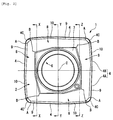
- an insert body 1 is formed in a polygonal plate shape using a hard material such as sintered hard alloy, and specifically, in the present embodiment, the drill insert is formed in an approximately square plate shape.
- One square surface of the insert body 1 is a rake face 2, four side faces which are disposed around the rake face 2 are flank faces 3, and a cutting blade 4 is formed on each of intersection ridge portions between the rake face 2 and the four flank faces 3.
- the other square surface of the insert body 1 is a seating face 5, and an attachment hole 6 penetrating the insert body 1 is formed from the center of the rake face 2 to the center of the seating face 5.
- the insert body 1 is formed so as to be rotationally symmetrical for each 90° around an insert center line C passing through the center of the attachment hole 6, and the seating face 5 is a flat face perpendicular to the insert center line C.
- each of the flank faces 3 is inclined so as to gradually retreat toward the inside of the insert body 1 from the cutting blade 4 toward the seating face 5 in the direction of the insert center line C, a clearance angle is formed on the cutting blade 4, and the drill insert of the present embodiment is a positive type insert.
- the flank face 3 is inclined to retreat toward the inside of the insert body 1 so as to have a plurality of steps from from the cutting blade 4 toward the seating face 5.
- a planar boss face 7 perpendicular to the insert center line C is formed around the attachment hole 6 in the center of the rake face 2, and the boss face 7 is positioned so as to most protrude from the rake face 2 in the direction of the insert center line C.
- breaker grooves 8 are formed over the entire circumference of the rake face 2 around the boss face 7, and each of the breaker groove 8 has a bottom surface 8A which is recessed to be inclined so as to gradually retreat in the direction of the insert center line C toward the inside of the rake face 2, and thereafter, is cut upward so as to rise via the concave curved face.
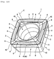
- the cutting blades 4 are disposed such that one of the four cutting blades 4 protrudes from the distal end of the drill body 11 and extends from the vicinity of an axis O on the inner circumferential side of the drill body 11 to the outer circumferential side, the end portion of the cutting blade 4 positioned in the vicinity of the axis O is one end portion A, and the end portion positioned on the outer circumferential of the drill body 11 is the other end portion B.
- a portion continuous with the one end portion A is a first cutting blade portion 4A
- a portion continuous with the other end portion B is a second cutting blade portion 4B
- the second cutting blade portion 4B is formed in a convex curve shape having a large curvature radius, a linear shape, or a combination thereof while the first cutting blade portion 4A linearly extends when viewed in a direction facing the rake face 2 in the direction of the insert center line C.
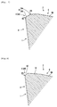
- the honing face 9 has a first convex curved face 9A continuous with the rake face 2 and a second convex curved face 9B continuous with the flank face 3, and as shown in Fig. 7 , in a cross section perpendicular to the cutting blade 4, the honing face 9 is formed such that a curvature radius R1 of the first convex curved face 9A is larger than a curvature radius R2 of the second convex curved face 9B.
- each of the first and second convex curved faces 9A and 9B is formed in an arc-shaped cross section having each of the constant curvature radii R1 and R2, and the honing face 9 is formed by the first and second convex curved faces 9A and 9B. That is, as shown in Fig.
- the first convex curved face 9A comes into contact with the bottom surface 8A of the breaker groove 8 which is inclined to gradually retreat in the direction of the insert center line C as being separated from the honing face 9 toward the inside of the rake face 2, the second convex curved face 9B comes into contact with the flank face 3, and the first and second convex curved faces 9A and 9B are formed so as to come into contact with each other.
- lengths along the arcs of the first and second convex curved faces 9A and 9B are formed such that the length of the first convex curved face 9A is longer than the length of the second convex curved face 9B.
- a land (positive land) 10 which gradually retreats in the direction of the insert center line C from the flank face 3 side toward the rake face 2 is formed, and the land 10 intersects the bottom surface 8A of the breaker groove 8 at an obtuse angle near to a straight angle therebetween.
- a third convex curved face 9C is formed between the land 10 and the flank face 3, and the third convex curved face 9C is also formed in an arc shape having a constant curvature radius R3 in the cross section orthogonal to the cutting blade 4.
- the curvature radius R3 of the third convex curved face 9C is set so as to be smaller than the curvature radius R1 of the first convex curved face 9A.
- the first cutting blade portion 4A and the second cutting blade portion 4B intersect each other so as to be bent at a slightly obtuse angle in a case where the first and second cutting blade portions 4A and 4B have linear shapes, and the second cutting blade portions 4B intersect the first cutting blade portion 4A so as to be similarly bent at an obtuse angle or is formed so as to come into contact with the first cutting blade portion 4A in a case where the second cutting blade portion 4B has a convex curve shape.
- a length from the one end portion A to the intersection or the contact between the first and second cutting blade portions 4A and 4B is longer than the length from the intersection or the contact to the other end portion B, that is, the first cutting blade portion 4A has a length which is 1/2 or more of a length of the cutting blade 4.
- a transition region may be formed in which the sectional shape of the cutting blade 4 is continuously changed from the honing face 9 of the first cutting blade portion 4A toward the land 10 of the second cutting blade portion 4B and the third convex curved face 9C.
- a corner blade 4C having a convex curve such as 1/4 arc or the like when viewed from the direction facing the rake face 2 is formed so as to come into contact with the first and second cutting blade portions 4A and 4B on both end portions A and B of two adjacent cutting blades 4.
- a width of the honing face 9 of the first cutting blade portion 4A is wider than a width of land 10 of the second cutting blade portion 4B, and the breaker groove 8 is formed such that the width of the breaker groove 8 gradually increases from the one end portion A of the cutting blade 4 toward the other end portion B.
- the drill body 11 is formed of a metal material such as a steel material, and the distal portion of the drill body 11 has a columnar shaped outline about an axis O.
- a rear end portion (not shown) is a shank portion and is held by a main spindle of a machine tool, the rear end portion moves to the distal side (lower side in the Figs.
- a pair of scrape discharge grooves 12A and 12B is formed on the outer circumference of the distal portion of the drill body 11, and in the present embodiment, the scrape discharge grooves 12A and 12B are formed so as to be slightly twisted to the rear side in the drill rotation direction T around the axis O toward the rear end side on the sides opposite to each other with an interval therebetween in the circumferential direction.
- an inner circumferential insert attachment seat 13A which opens to the distal face of the drill body 11 is formed on the distal inner circumferential portion of a wall face of one scrape discharge groove (right upper scrape discharge groove in Fig.
- an outer circumferential insert attachment seat 13B which opens to the distal face and the outer circumferential surface of the drill body 11 is formed on the distal outer circumferential portion of a wall face of the other scrape discharge groove (left lower scrape discharge groove in Fig. 10 ) 12B in the drill rotation direction T.
- Screw holes 13C is formed on bottom surfaces of the inner and outer circumferential insert attachment seats 13A and 13B in the drill rotation direction T.
- the rake face 2 is directed to the drill rotation direction T, as described above, one among the four cutting blades 4 protrudes from the distal end of the drill body 11 and is seated on the inner circumferential insert attachment seat 13A, a clamp screw 14 inserted into the attachment hole 6 is screwed to the screw hole 13C, and the drill insert of the first embodiment is detachably attached to the drill body 11.
- the one end portion A is positioned in the vicinity of the axis O
- the outer end portion B is positioned on the outer circumferential side of the drill body 11, and the first cutting blade portion 4A intersects the axis O and is disposed in the vicinity of the axis O.
- the other end portion B is positioned on the most distal end in the direction of the axis O, and the cutting blade 4 is disposed so as to be gently inclined to the rear end side in the direction of the axis toward the one end portion A.
- the first cutting blade portion 4A extends over the axis O from the intersection between the first and second cutting blade portions 4A and 4B toward the inner circumferential side of the drill body 11, that is, the one end portion A is positioned on the side opposite to the axis with respect to the intersection.
- an outer circumferential drill insert is also detachably attached to the outer circumferential insert attachment seat 13B by the clamp screw 14.
- an insert body 15 of the outer circumferential drill insert is formed in a square plate shape using a hard material such as sintered hard alloy.
- the present embodiment does not have the first cutting blade portion 4A having the honing face 9 of the first embodiment, and as shown in Fig. 12 , chip breakers 17 are formed on the rake face in the drill rotation direction T along cutting blades 16.
- one cutting blade 16 protrudes from the distal end of the drill body 11, the one cutting blade 16 is positioned on the slightly further rear end side with respect to the protruding cutting blade 4 of the drill insert of the first embodiment shown in Fig. 9 , and the outer circumferential drill insert is attached to the drill body such that rotation trajectories around the axis O overlap each other.
- the outer circumferential end of the one cutting blade 16 of the attached outer circumferential drill insert slightly further protrudes from the outer circumferential side relative to the outer circumference of the distal portion of the drill body 11.
- the inner circumferential portion of a hole drilled in the workpiece is cut by the drill insert of the first embodiment, and the outer circumferential portion of the hole is cut by the outer circumferential drill insert. Accordingly, in the cutting blade 4 which protrudes from the distal end of the drill body 11 of the inner circumferential drill insert of the first embodiment, particularly, a circumferential speed and a cutting speed approach zero in the first cutting blade portion 4A on the axis O side intersecting the axis O, and a cutting load or cutting resistance increases.
- the first convex curved face 9A continuous with the rake face 2 and the second convex curved face 9B continuous with the flank face 3 are provided, and the honing face 9 which gradually rises from the flank face 3 toward the rake face 2 is formed. Accordingly, it is possible to ensure sufficient chipping resistance with respect to the cutting load or the cutting resistance.
- the honing face 9 gradually rises in the direction of the insert center line C from the flank face 3 toward the rake face 2, first, it is possible to increase a lip angle between the honing face 9 which substantially functions as a cutting blade edge in the first cutting blade portion 4A and the flank face 3.
- the second convex curved face 9B continuous with the flank face 3 is formed on the intersection ridge portion between the honing face 9 of the first cutting blade portion 4A and the flank face 3, strength of the cutting blade is ensured, and it is possible to obtain sufficient chipping resistance with respect to the cutting load or the cutting resistance.
- the first convex curved face 9A continuous with the rake face 2 is formed on the rake face 2 side of the honing face 9, and the curvature radius R1 of the first convex curved face 9A is larger than the curvature radius R2 of the second convex curved face 9B. Accordingly, since the first convex curved face 9A has the arc which is more gentle than that of the second convex curved face 9B in the cross section orthogonal to the cutting blade 4, friction resistance decreases when scraps or chips scratch the honing face 9, and it is possible to prevent cutting heat due to the friction from increasing. Accordingly, it is possible to prevent occurrence of welding even if the workpiece is stainless steel, and it is possible to prevent damage of the cutting blade 4 due to the welding.
- the first cutting blade portion 4A has the length which is 1/2 or more of the length of the cutting blade 4 protruding from the distal end of the drill body 11, when the drill insert is attached to the inner circumferential side of the distal portion of the drill body 11, the first cutting blade portion 4A having a sufficient length can be disposed in the vicinity of the axis O, and it is possible to further reliably ensure the chipping resistance. That is, if the length of the first cutting blade portion 4A is less than 1/2 of the entire length of one cutting blade 4, when an excessive cutting load or cutting resistance is applied, there is a concern that it is not possible to reliably ensure the chipping resistance on the other end portion B side of the cutting blade 4 rather than the first cutting blade portion 4A.
- the breaker groove 8 which has the bottom surface 8A continuous with the honing face 9 is formed on the rake face 2, and the bottom surface 8A of the breaker groove 8 is inclined to gradually retreat in the direction of the insert center line C as the bottom surface is separated from the honing face 9, even when the honing face 9 which gradually rises in the direction of the insert center line C is formed on the first cutting blade portion 4A to ensure the chipping resistance, it is possible to prevent the cutting resistance from increasing more than is needed.
- the bottom surface 8A has the convex curved face of the curvature radius R1 on the honing face 9 side and may come into contact with the first convex curve 9A as described above, or may intersect the first convex curved face 9A at an obtuse angle.
- the land 10 is formed, which is inclined so as to gradually retreat in the direction of the insert center line C from the flank face 3 side toward the rake face 2.
- the third convex curved face 9C is formed on the intersection ridge portion between the land 10 and the flank face 3, it is possible to prevent damage of the cutting blade 4 on the second cutting blade portion 4B.
- the curvature radius R3 of the third convex curved face 9C is smaller than the curvature radius R3 of the first convex curved face 9A in the first cutting blade portion 4A, it is possible to prevent the cutting resistance from increasing more than is needed while preventing damage of the cutting blade 4 on the second cutting blade portion 4B.
- the outer circumferential drill insert is provided, which is positioned on the outer circumferential side of the drill body 11 from the second cutting blade portion 4B of the drill insert of the first embodiment and cuts the outer circumferential portion of the drilled hole. Since the outer circumferential drill insert does not have the first cutting blade portion 4A having the honing face 9 of the first embodiment and the chip breakers 17 are formed on the rake face along the cutting blade 16, even when the outer circumferential drill insert is separated from the axis O and much more scraps are generated in the outer circumferential drill insert than in the drill insert of the first embodiment, it is possible to reliably remove the scraps.
- the drill insert of the first embodiment may be attached to the outer circumferential insert attachment seat 13B.
- the second cutting blade portion 4B in which the land 10 is formed on the other end portion B side of the cutting blade 4 is provided.
- the entire length of the cutting blade 4 may be the first cutting blade portion 4A on which the honing face 9 is formed, which includes the first convex curved face 9A continuous with the rake face 2 and the second convex curved face 9B continuous with the flank face 3 and gradually rises from the flank face 3 toward the rake face 2.
- the same reference numerals are assigned to the portions common to the first embodiment.
- the shape of the cross section over the entire length of the cutting blade 4 is the shape shown in Fig. 7 , and it is possible to ensure chipping resistance with respect to a cutting load or cutting resistance and chipping resistance with respect to welding. Accordingly, it is possible to provide a drill insert having a longer service life.
- the curvature radii R1 and R2 of the first and second convex curved faces 9A and 9B or the width of the honing face 9 are approximately constant over the entire length of the cutting blade 4.
- the drill insert of the second embodiment is attached to the inner circumferential side of the drill body 11
- the drill insert of the first embodiment instead of the outer circumferential drill insert of the cutting edge replacement type drill of the embodiment may be attached to the outer circumferential side.
- the drill insert of the second embodiment may be attached to both the inner and outer circumferential insert attachment seats 13A and 13B of the drill body 11.
- the drill insert of the first embodiment may be attached to the drill body 11 of the cutting edge replacement type drill having one blade in which only the inner circumferential insert attachment seat 13A is formed.
- the drill insert of the second embodiment may be attached to the cutting edge replacement type drill having one blade.
Abstract
Description
- The present invention relates to a drill insert which is detachably attached to a distal portion of a drill body of a cutting edge replacement type drill, and a cutting edge replacement type drill to which the drill insert is detachably attached.
- As the drill insert and the cutting edge replacement type drill, a drill insert is disclosed in
PTL 1, in which cutting blades are formed on one pair of side ridge portions continuous with one apex of rake face forming a polygon of a polygonal flat plate-shaped insert body, an inner circumferential side chip breaker protrudes from the rake face continuous with one of the cutting blades, and an outer circumferential side chip breaker which is recessed from the rake face is formed on the other one of the cutting blades. - In the drill insert disclosed in
PTL 1, the drill inserts having the same shape and the same size as each other are attached to the inner circumferential side and the outer circumferential side of the distal portion of a drill body, the cutting blade on which the inner circumferential side chip breaker is formed is used for drilling in the inner circumferential side drill insert, and the cutting blade on which the outer circumferential side chip breaker is formed is used for drilling in the outer circumferential side drill insert. - In addition,
PTL 2 discloses a drill insert, in which the drill insert, which is attached to the inner circumferential side of the distal portion of a drill body out of drill inserts attached to the inner circumferential side and the outer circumferential side of the distal portion of the drill body, is set to a central insert, and a rake angle of an operating edge (cutting blade) of the square central insert increases in a rotation axis of a drill in a region in which the inner circumferential drill insert and the outer circumferential drill insert overlap each other. In the drill insert disclosed inPTL 2, a chamfered edge (negative land) is formed on the cutting blade on the rotation axis, and has a negative angle of approximately 15°. -
- [PTL 1]
Japanese Patent No. 3022002 - [PTL 2]
Japanese Patent No. 4394180 - However, for example, as disclosed in
PTL 2, in the cutting edge replacement type drill, a circumferential speed by the rotation of the drill body decreases from the outer circumferential side of the drill body toward the inner circumferential side, and the circumferential speed and a cutting speed on the rotation axis of the drill body become zero. Accordingly, in the drill insert attached to the inner circumferential side of the drill body, particularly, the cutting blade cuts a workpiece while squeezing the workpiece in the vicinity of the rotation axis, and a cutting load or cutting resistance increases. - However, in the drill insert disclosed in
PTL 1, when the inner circumferential side drill insert is used for cutting, only the flat rake face is formed between one cutting blade disposed in the vicinity of the rotation axis and the inner circumferential side chip breaker. Accordingly, strength of the cutting blade is insufficient, and it is difficult to ensure sufficient chipping resistance with respect to a large cutting load or large cutting resistance. - Meanwhile, in the drill insert and the cutting edge replacement type drill disclosed in
PTL 2, the negative land having the negative angle is formed on the cutting blade on the rotation axis of the drill body, and a certain degree of strength of the cutting blade can be ensured. However, the breaker groove is formed on the rake face on the inner circumferential side of the drill body slightly separated from the rotation axis, and the rake angle has a positive angle within a range of 5° to 20°. Accordingly, similarly to the drill insert disclosed inPTL 1, it is difficult to ensure chipping resistance. - In addition, in a case where a workpiece to be drilled is formed of stainless steel or the like, particularly, as described above, in the vicinity of the rotation axis of the drill body in which the cutting blade performs cutting while squeezing the workpiece, welding of scraps or chips easily occurs on the cutting edge of the cutting blade due to an increase of cutting heat according to the increase of the cutting resistance. Accordingly, when weld deposits are peeled due to the welding, the cutting blade may be damaged. Particularly, as the drill insert disclosed in
PTL 2, if the negative land is formed on the cutting blade on the rotation axis of the drill body, since the cutting resistance increases and the cutting heat increases even though the strength of the cutting blade can be ensured, damage due to the welding easily occurs. - The present invention is made in consideration of the above-described circumstances, and an object thereof is to provide a drill insert which is attached to the inner circumferential side of the distal portion of the drill body, particularly, can ensure sufficient chipping resistance with respect to a cutting load or cutting resistance, and can prevent damage due to the welding, and a cutting edge replacement type drill which is detachably attached to the drill insert.
- In order to solve the above-described problems and achieve the object, according to an aspect of the present invention, there is provided a drill insert which is detachably attached to a distal portion of a drill body which is rotated around an axis, in which a polygon face of a polygonal plate-shaped insert body is a rake face, a side face of the insert body disposed around the rake face is a flank face, and a cutting blade is formed on a ridge portion in which the rake face and the flank face intersect each other. In addition, the cutting blade includes a honing face which is formed on a first cutting blade portion continuous with at least one end portion of both end portions of the cutting blade and which gradually rises from the flank face toward the rake face, the honing face includes a first convex curved face continuous with the rake face and a second convex curved face continuous with the flank face, and in a cross section orthogonal to the cutting blade, a curvature radius of the first convex curved face is larger than a curvature radius of the second convex curved face.
- In addition, according to another aspect of the present invention, there is provided a cutting edge replacement type drill, in which the drill insert configured as described above is detachably attached to a distal portion of a drill body which is rotated around an axis such that the cutting blade protrudes from the distal end of the drill body, the one end portion of the cutting blade is positioned in the vicinity of the axis and the other end portion of both end portions of the cutting blade is positioned on the outer circumferential side of the drill body when viewed from a rotation direction of the drill body, and the first cutting blade portion and the axis intersect each other.
- Accordingly, in the drill insert having the above-described configuration which is attached to the drill body, the first cutting blade portion, on which a negative honing face gradually rising from the flank face of the cutting blade toward the rake face is formed, is positioned in the vicinity of the axis of the inner circumferential side of the drill body. Therefore, since a lip angle of the first cutting blade portion can increase and the honing face includes the first convex curved face continuous with the rake face and the second convex curved face continuous with the flank face, it is possible to ensure strength of the cutting blade in an intersection ridge portion between the honing face substantially functioning as the edge of the cutting blade and the flank face, by the second convex curved face, and it is possible to obtain sufficient chipping resistance with respect to a cutting load or cutting resistance.
- Meanwhile, the first convex curved face, which has the curvature radius larger than that of the second convex curved face and has an arc gentler than that of the second convex curved face, is formed on the rake face side of the honing face, and it is possible to decrease resistance when scraps or chips scratch. Accordingly, even though a workpiece is stainless steel or the like, it is possible to prevent occurrence of welding due to an increase of cutting heat in the first cutting blade portion positioned on the inner circumferential side of the drill body, and it is possible to prevent damage of the cutting blade due to the welding.
- Here, the first cutting blade portion may have a length which is 1/2 or more of a length of the cutting blade. Accordingly, it is possible to reliably ensure the chipping resistance in a portion in which the cutting load or the cutting resistance increases in the vicinity of the axis when the drill insert is attached to the drill body. That is, if the length of the first cutting blade portion on which the honing face having the first and second convex curved faces is formed is less than 1/2 of the length of the cutting blade, there is a concern that it is not possible to reliably ensure the chipping resistance on the other end portion side of the cutting blade rather than the first cutting blade portion according to the applied cutting load or the cutting resistance.
- In addition, a breaker groove which has a bottom surface continuous with the honing face may be formed on the rake face, and the bottom surface of the breaker groove may be formed so as to be inclined to gradually retreat as the bottom surface is separated from the honing face. Accordingly, it is possible to prevent the cutting resistance from increasing more than is needed by the honing face rising in a negative shape.
- Moreover, the entire length portion of the cutting blade may be the first cutting blade portion. However, if the first cutting blade portion having a sufficient length can be ensured on the inner circumferential side of the drill body, a land which gradually retreats from the flank face side toward the rake face may be formed on a second cutting blade portion continuous with the other end portion of both end portions of the cutting blade, on the outer circumferential side of the drill body in which a cutting speed increases in the cutting blade protruding from the distal end of the drill body. Accordingly, it is possible to further decrease the cutting resistance by increasing sharpness of the cutting blade.
- However, in a case where the second cutting blade portion having the land is provided on the other end portion side of the cutting blade, particularly, in a case where a workpiece such as stainless steel is drilled, preferably, a third convex curved face is formed between the flank face and the land of the second cutting blade portion to ensure the strength of the cutting blade. In addition, in the cross section orthogonal to the cutting blade, a curvature radius of the third convex curved face may be smaller than the curvature radius of the first convex curved face. Accordingly, it is possible to prevent the cutting resistance from increasing more than is needed while ensuring sufficient chipping resistance in the second cutting blade portion.
- As described above, according to the present invention, it is possible to ensure sufficient chipping resistance with respect to the cutting load or the cutting resistance applied to the cutting blade in the vicinity of the axis of the drill body, and it is possible to prevent damage due to welding in a case where a workpiece such as stainless steel is drilled.
-
-
Fig. 1 is a perspective view showing a first embodiment of a drill insert of the present invention. -
Fig. 2 is a plan view of the embodiment shown inFig. 1 . -
Fig. 3 is a side view of the embodiment shown inFig. 1 . -
Fig. 4 is a sectional view taken along line X-X inFig. 2 . -
Fig. 5 is a sectional view taken along line Y-Y inFig. 2 . -
Fig. 6 is a sectional view taken along line Z-Z inFig. 2 . -
Fig. 7 is an enlarged sectional view of a lower cutting blade (first cutting blade portion) inFig. 4 . -
Fig. 8 is an enlarged sectional view of a lower cutting blade (second cutting blade portion) inFig. 6 . -
Fig. 9 is a plan view of a distal portion of a drill body showing an embodiment of a cutting edge replacement type drill of the present invention to which the drill insert of the embodiment shown inFigs 1 to 8 is attached. -
Fig. 10 is a front view of the cutting edge replacement type drill shown inFig. 9 . -
Fig. 11 is a side view of the cutting edge replacement type drill shown inFig. 9 . -
Fig. 12 is a bottom view of the cutting edge replacement type drill shown inFig. 9 . -
Fig. 13 is a perspective view showing a second embodiment of a drill insert of the present invention. -
Fig. 14 is a plan view showing the embodiment shown inFig. 13 . -
Fig. 15 is a side view of the embodiment shown inFig. 13 . -
Fig. 16 is a sectional view taken along line X-X inFig. 14 . -
Fig. 17 is a sectional view taken along line Y-Y inFig. 14 . -
Fig. 18 is a sectional view taken along line Z-Z inFig. 14 . -
Figs. 1 to 8 show a first embodiment of a drill insert of the present invention,Figs. 9 to 12 show an embodiment of a cutting edge replacement type drill of the present invention to which the drill insert of the first embodiment is attached. In the drill insert of the present embodiment, aninsert body 1 is formed in a polygonal plate shape using a hard material such as sintered hard alloy, and specifically, in the present embodiment, the drill insert is formed in an approximately square plate shape. - One square surface of the
insert body 1 is arake face 2, four side faces which are disposed around therake face 2 are flank faces 3, and acutting blade 4 is formed on each of intersection ridge portions between therake face 2 and the four flank faces 3. In addition, the other square surface of theinsert body 1 is aseating face 5, and anattachment hole 6 penetrating theinsert body 1 is formed from the center of therake face 2 to the center of theseating face 5. Theinsert body 1 is formed so as to be rotationally symmetrical for each 90° around an insert center line C passing through the center of theattachment hole 6, and theseating face 5 is a flat face perpendicular to the insert center line C. - In addition, each of the flank faces 3 is inclined so as to gradually retreat toward the inside of the
insert body 1 from thecutting blade 4 toward theseating face 5 in the direction of the insert center line C, a clearance angle is formed on thecutting blade 4, and the drill insert of the present embodiment is a positive type insert. In addition, theflank face 3 is inclined to retreat toward the inside of theinsert body 1 so as to have a plurality of steps from from thecutting blade 4 toward theseating face 5. - A
planar boss face 7 perpendicular to the insert center line C is formed around theattachment hole 6 in the center of therake face 2, and theboss face 7 is positioned so as to most protrude from therake face 2 in the direction of the insert center line C. In addition,breaker grooves 8 are formed over the entire circumference of therake face 2 around theboss face 7, and each of thebreaker groove 8 has abottom surface 8A which is recessed to be inclined so as to gradually retreat in the direction of the insert center line C toward the inside of therake face 2, and thereafter, is cut upward so as to rise via the concave curved face. - Meanwhile, when the
insert body 1 is attached to a distal portion of adrill body 11 described below, thecutting blades 4 are disposed such that one of the fourcutting blades 4 protrudes from the distal end of thedrill body 11 and extends from the vicinity of an axis O on the inner circumferential side of thedrill body 11 to the outer circumferential side, the end portion of thecutting blade 4 positioned in the vicinity of the axis O is one end portion A, and the end portion positioned on the outer circumferential of thedrill body 11 is the other end portion B. Moreover, in thecutting blade 4, a portion continuous with the one end portion A is a firstcutting blade portion 4A, a portion continuous with the other end portion B is a secondcutting blade portion 4B, and the secondcutting blade portion 4B is formed in a convex curve shape having a large curvature radius, a linear shape, or a combination thereof while the firstcutting blade portion 4A linearly extends when viewed in a direction facing therake face 2 in the direction of the insert center line C. - In addition, in the first
cutting blade portion 4A, round honing is performed on thecutting blade 4 so as to form a honingface 9, and the honingface 9 is formed so as to gradually rise in the direction of the insert center line C from theflank face 3 toward therake face 2. Moreover, the honingface 9 has a first convexcurved face 9A continuous with therake face 2 and a second convexcurved face 9B continuous with theflank face 3, and as shown inFig. 7 , in a cross section perpendicular to thecutting blade 4, the honingface 9 is formed such that a curvature radius R1 of the first convexcurved face 9A is larger than a curvature radius R2 of the second convexcurved face 9B. - Here, in the present embodiment, each of the first and second convex
curved faces face 9 is formed by the first and second convexcurved faces Fig. 7 , the first convexcurved face 9A comes into contact with thebottom surface 8A of thebreaker groove 8 which is inclined to gradually retreat in the direction of the insert center line C as being separated from the honingface 9 toward the inside of therake face 2, the second convexcurved face 9B comes into contact with theflank face 3, and the first and second convexcurved faces cutting blade 4, lengths along the arcs of the first and second convexcurved faces curved face 9A is longer than the length of the second convexcurved face 9B. - In addition, as shown in
Fig. 8 , in the secondcutting blade portion 4B, a land (positive land) 10 which gradually retreats in the direction of the insert center line C from theflank face 3 side toward therake face 2 is formed, and theland 10 intersects thebottom surface 8A of thebreaker groove 8 at an obtuse angle near to a straight angle therebetween. In addition, a third convexcurved face 9C is formed between theland 10 and theflank face 3, and the third convexcurved face 9C is also formed in an arc shape having a constant curvature radius R3 in the cross section orthogonal to thecutting blade 4. However, the curvature radius R3 of the third convexcurved face 9C is set so as to be smaller than the curvature radius R1 of the first convexcurved face 9A. - In addition, when viewed from the direction facing the
rake face 2 in the direction of the insert center line C, the firstcutting blade portion 4A and the secondcutting blade portion 4B intersect each other so as to be bent at a slightly obtuse angle in a case where the first and secondcutting blade portions cutting blade portions 4B intersect the firstcutting blade portion 4A so as to be similarly bent at an obtuse angle or is formed so as to come into contact with the firstcutting blade portion 4A in a case where the secondcutting blade portion 4B has a convex curve shape. A length from the one end portion A to the intersection or the contact between the first and secondcutting blade portions cutting blade portion 4A has a length which is 1/2 or more of a length of thecutting blade 4. In addition, in the portion in which the first and second convexcurved face cutting blade 4 is continuously changed from the honingface 9 of the firstcutting blade portion 4A toward theland 10 of the secondcutting blade portion 4B and the third convexcurved face 9C. - In addition, in each of corner portions having a square face (polygon face) configured of the
rake face 2, acorner blade 4C having a convex curve such as 1/4 arc or the like when viewed from the direction facing therake face 2 is formed so as to come into contact with the first and secondcutting blade portions adjacent cutting blades 4. Moreover, a width of the honingface 9 of the firstcutting blade portion 4A is wider than a width ofland 10 of the secondcutting blade portion 4B, and thebreaker groove 8 is formed such that the width of thebreaker groove 8 gradually increases from the one end portion A of thecutting blade 4 toward the other end portion B. - In the cutting edge replacement type drill of an embodiment of the present invention to which the drill insert of the first embodiment is detachably attached, the
drill body 11 is formed of a metal material such as a steel material, and the distal portion of thedrill body 11 has a columnar shaped outline about an axis O. In the cutting edge replacement type drill, a rear end portion (not shown) is a shank portion and is held by a main spindle of a machine tool, the rear end portion moves to the distal side (lower side in theFigs. 9 ,11 , and12 ) in the direction of the axis O while rotating in a drill rotation direction T around the axis O, and a workpiece such as stainless steel is drilled by the drill insert which is attached to the distal portion of thedrill body 11. - A pair of
scrape discharge grooves drill body 11, and in the present embodiment, thescrape discharge grooves scrape discharge grooves insert attachment seat 13A which opens to the distal face of thedrill body 11 is formed on the distal inner circumferential portion of a wall face of one scrape discharge groove (right upper scrape discharge groove inFig. 10 ) 12A in the drill rotation direction T, and an outer circumferentialinsert attachment seat 13B which opens to the distal face and the outer circumferential surface of thedrill body 11 is formed on the distal outer circumferential portion of a wall face of the other scrape discharge groove (left lower scrape discharge groove inFig. 10 ) 12B in the drill rotation direction T. -
Screw holes 13C is formed on bottom surfaces of the inner and outer circumferentialinsert attachment seats rake face 2 is directed to the drill rotation direction T, as described above, one among the fourcutting blades 4 protrudes from the distal end of thedrill body 11 and is seated on the inner circumferentialinsert attachment seat 13A, aclamp screw 14 inserted into theattachment hole 6 is screwed to thescrew hole 13C, and the drill insert of the first embodiment is detachably attached to thedrill body 11. - In addition, in the attached drill insert of the first embodiment, when viewed from the drill rotation direction T facing the
rake face 2, as shown inFig. 9 , in thecutting blade 4 which protrudes from the distal end of thedrill body 11, the one end portion A is positioned in the vicinity of the axis O, the outer end portion B is positioned on the outer circumferential side of thedrill body 11, and the firstcutting blade portion 4A intersects the axis O and is disposed in the vicinity of the axis O. Moreover, in thecutting blade 4 which protrudes from the distal end of thedrill body 11, the other end portion B is positioned on the most distal end in the direction of the axis O, and thecutting blade 4 is disposed so as to be gently inclined to the rear end side in the direction of the axis toward the one end portion A. Moreover, the firstcutting blade portion 4A extends over the axis O from the intersection between the first and secondcutting blade portions drill body 11, that is, the one end portion A is positioned on the side opposite to the axis with respect to the intersection. - Meanwhile, an outer circumferential drill insert is also detachably attached to the outer circumferential
insert attachment seat 13B by theclamp screw 14. Similarly to the drill insert of the first embodiment, aninsert body 15 of the outer circumferential drill insert is formed in a square plate shape using a hard material such as sintered hard alloy. However, differently from the first embodiment, in the outer circumferential drill insert, the present embodiment does not have the firstcutting blade portion 4A having the honingface 9 of the first embodiment, and as shown inFig. 12 ,chip breakers 17 are formed on the rake face in the drill rotation direction T along cuttingblades 16. - In the outer circumferential drill insert, one
cutting blade 16 protrudes from the distal end of thedrill body 11, the onecutting blade 16 is positioned on the slightly further rear end side with respect to the protrudingcutting blade 4 of the drill insert of the first embodiment shown inFig. 9 , and the outer circumferential drill insert is attached to the drill body such that rotation trajectories around the axis O overlap each other. In addition, the outer circumferential end of the onecutting blade 16 of the attached outer circumferential drill insert slightly further protrudes from the outer circumferential side relative to the outer circumference of the distal portion of thedrill body 11. - Accordingly, in the cutting edge replacement type drill of the embodiment of the present invention configured as described above, as shown in
Fig. 9 , the inner circumferential portion of a hole drilled in the workpiece is cut by the drill insert of the first embodiment, and the outer circumferential portion of the hole is cut by the outer circumferential drill insert. Accordingly, in thecutting blade 4 which protrudes from the distal end of thedrill body 11 of the inner circumferential drill insert of the first embodiment, particularly, a circumferential speed and a cutting speed approach zero in the firstcutting blade portion 4A on the axis O side intersecting the axis O, and a cutting load or cutting resistance increases. However, in the firstcutting blade portion 4A, the first convexcurved face 9A continuous with therake face 2 and the second convexcurved face 9B continuous with theflank face 3 are provided, and the honingface 9 which gradually rises from theflank face 3 toward therake face 2 is formed. Accordingly, it is possible to ensure sufficient chipping resistance with respect to the cutting load or the cutting resistance. - That is, since the honing
face 9 gradually rises in the direction of the insert center line C from theflank face 3 toward therake face 2, first, it is possible to increase a lip angle between the honingface 9 which substantially functions as a cutting blade edge in the firstcutting blade portion 4A and theflank face 3. In addition, since the second convexcurved face 9B continuous with theflank face 3 is formed on the intersection ridge portion between the honingface 9 of the firstcutting blade portion 4A and theflank face 3, strength of the cutting blade is ensured, and it is possible to obtain sufficient chipping resistance with respect to the cutting load or the cutting resistance. - In addition, the first convex
curved face 9A continuous with therake face 2 is formed on therake face 2 side of the honingface 9, and the curvature radius R1 of the first convexcurved face 9A is larger than the curvature radius R2 of the second convexcurved face 9B. Accordingly, since the first convexcurved face 9A has the arc which is more gentle than that of the second convexcurved face 9B in the cross section orthogonal to thecutting blade 4, friction resistance decreases when scraps or chips scratch the honingface 9, and it is possible to prevent cutting heat due to the friction from increasing. Accordingly, it is possible to prevent occurrence of welding even if the workpiece is stainless steel, and it is possible to prevent damage of thecutting blade 4 due to the welding. - Moreover, in the drill insert of the first embodiment, since the first
cutting blade portion 4A has the length which is 1/2 or more of the length of thecutting blade 4 protruding from the distal end of thedrill body 11, when the drill insert is attached to the inner circumferential side of the distal portion of thedrill body 11, the firstcutting blade portion 4A having a sufficient length can be disposed in the vicinity of the axis O, and it is possible to further reliably ensure the chipping resistance. That is, if the length of the firstcutting blade portion 4A is less than 1/2 of the entire length of onecutting blade 4, when an excessive cutting load or cutting resistance is applied, there is a concern that it is not possible to reliably ensure the chipping resistance on the other end portion B side of thecutting blade 4 rather than the firstcutting blade portion 4A. - Moreover, since the
breaker groove 8 which has thebottom surface 8A continuous with the honingface 9 is formed on therake face 2, and thebottom surface 8A of thebreaker groove 8 is inclined to gradually retreat in the direction of the insert center line C as the bottom surface is separated from the honingface 9, even when the honingface 9 which gradually rises in the direction of the insert center line C is formed on the firstcutting blade portion 4A to ensure the chipping resistance, it is possible to prevent the cutting resistance from increasing more than is needed. In addition, thebottom surface 8A has the convex curved face of the curvature radius R1 on the honingface 9 side and may come into contact with the firstconvex curve 9A as described above, or may intersect the first convexcurved face 9A at an obtuse angle. - Meanwhile, in the present embodiment, with respect to the first
cutting blade portion 4A of the one end portion A side of thecutting blade 4 in which the chipping resistance is ensured, in the secondcutting blade portion 4B on the other end portion B side of thecutting blade 4 which is disposed on the outer circumferential side of the distal end of thedrill body 11, theland 10 is formed, which is inclined so as to gradually retreat in the direction of the insert center line C from theflank face 3 side toward therake face 2. Accordingly, it is possible to increase sharpness of thecutting blade 4 on the outer circumferential side of thecutting blade 4 in which is a certain degree of circumferential speed is generated to ensure the cutting speed, and even when much more scraps are generated on the outer circumferential side than the vicinity of the axis O, it is possible to further decrease the cutting resistance. - In addition, even in the case where the
land 10 is formed on the secondcutting blade portion 4B, in the present embodiment, since the third convexcurved face 9C is formed on the intersection ridge portion between theland 10 and theflank face 3, it is possible to prevent damage of thecutting blade 4 on the secondcutting blade portion 4B. In addition, since the curvature radius R3 of the third convexcurved face 9C is smaller than the curvature radius R3 of the first convexcurved face 9A in the firstcutting blade portion 4A, it is possible to prevent the cutting resistance from increasing more than is needed while preventing damage of thecutting blade 4 on the secondcutting blade portion 4B. - In addition, in the cutting edge replacement type drill of the present embodiment, the outer circumferential drill insert is provided, which is positioned on the outer circumferential side of the
drill body 11 from the secondcutting blade portion 4B of the drill insert of the first embodiment and cuts the outer circumferential portion of the drilled hole. Since the outer circumferential drill insert does not have the firstcutting blade portion 4A having the honingface 9 of the first embodiment and thechip breakers 17 are formed on the rake face along thecutting blade 16, even when the outer circumferential drill insert is separated from the axis O and much more scraps are generated in the outer circumferential drill insert than in the drill insert of the first embodiment, it is possible to reliably remove the scraps. However, according to machining conditions or the like, the drill insert of the first embodiment may be attached to the outer circumferentialinsert attachment seat 13B. - Moreover, in the drill insert of the first embodiment, the second
cutting blade portion 4B in which theland 10 is formed on the other end portion B side of thecutting blade 4 is provided. However, in a case where there is a concern that a large cutting load or large cutting resistance is applied to the entire length of thecutting blade 4 of the drill insert attached to the inner circumferential side of thedrill body 11 according to machining conditions, the size of theinsert body 1, the length of thecutting blade 4, or the like, as a drill insert of a second embodiment of the present invention shown inFigs. 13 to 18 , the entire length of thecutting blade 4 may be the firstcutting blade portion 4A on which the honingface 9 is formed, which includes the first convexcurved face 9A continuous with therake face 2 and the second convexcurved face 9B continuous with theflank face 3 and gradually rises from theflank face 3 toward therake face 2. In addition, in the second embodiment, the same reference numerals are assigned to the portions common to the first embodiment. - Accordingly, in the drill insert of the second embodiment, the shape of the cross section over the entire length of the
cutting blade 4 is the shape shown inFig. 7 , and it is possible to ensure chipping resistance with respect to a cutting load or cutting resistance and chipping resistance with respect to welding. Accordingly, it is possible to provide a drill insert having a longer service life. In addition, in the second embodiment, the curvature radii R1 and R2 of the first and second convexcurved faces face 9 are approximately constant over the entire length of thecutting blade 4. - Moreover, in a case where there is a concern that a large cutting load or large cutting resistance is applied to a portion exceeding the entire length of the
cutting blade 4 of the drill insert attached to the inner circumferential side of thedrill body 11, the drill insert of the second embodiment is attached to the inner circumferential side of thedrill body 11, the drill insert of the first embodiment instead of the outer circumferential drill insert of the cutting edge replacement type drill of the embodiment may be attached to the outer circumferential side. In this case, it is possible to ensure high chipping resistance within a range from the vicinity of the axis O of thedrill body 11 to the firstcutting blade portion 4A of the outer circumferential drill insert of the first embodiment. Of course, the drill insert of the second embodiment may be attached to both the inner and outer circumferentialinsert attachment seats drill body 11. - In addition, in a case where the inner diameter of the drilled hole is small, the outer diameter of the distal portion of the
drill body 11 is small, and a large cutting load or large cutting resistance is applied to only the vicinity of the axis O, the drill insert of the first embodiment may be attached to thedrill body 11 of the cutting edge replacement type drill having one blade in which only the inner circumferentialinsert attachment seat 13A is formed. In addition, in a case where a large cutting load or large cutting resistance is applied to the entire length of thecutting blade 4 even through the inner diameter of the drilled hole is small, the drill insert of the second embodiment may be attached to the cutting edge replacement type drill having one blade. Reference Signs List -
- 1: insert body
- 2: rake face
- 3: flank face
- 4: cutting blade
- 4A: first cutting blade portion
- 4B: second cutting blade portion
- 4C: corner blade
- 8: breaker groove
- 8A: bottom surface of
breaker groove 8 - 9: honing face
- 9A: first convex curved face
- 9B: second convex curved face
- 9C: third convex curved face
- 10: land
- 11: drill body
- 13A, 13B: inner and outer circumferential insert attachment seat
- A: one end portion of
cutting blade 4 - B: other end portion of
cutting blade 4 - C: insert center line
- R1 to R3: curvature radii of first to third convex
curved faces 9A to 9C - O: axis of
drill body 11 - T: drill rotation direction
Claims (6)
- A drill insert which is detachably attached to a distal portion of a drill body which is rotated around an axis,
wherein a polygon face of a polygonal plate-shaped insert body is a rake face, a side face of the insert body disposed around the rake face is a flank face, and a cutting blade is formed on a ridge portion in which the rake face and the flank face intersect each other,
wherein the cutting blade includes a honing face which is formed on a first cutting blade portion continuous with at least one end portion of both end portions of the cutting blade and which gradually rises from the flank face toward the rake face,
wherein the honing face includes a first convex curved face continuous with the rake face and a second convex curved face continuous with the flank face, and
wherein in a cross section orthogonal to the cutting blade, a curvature radius of the first convex curved face is larger than a curvature radius of the second convex curved face. - The drill insert according to claim 1,
wherein the first cutting blade portion has a length which is 1/2 or more of a length of the cutting blade. - The drill insert according to claim 1 or 2,
wherein a breaker groove which has a bottom surface continuous with the honing face is formed on the rake face, and the bottom surface of the breaker groove is inclined to gradually retreat as the bottom surface is separated from the honing surface. - The drill insert according to any one of claims 1 to 3,
wherein a land which gradually retreats from the flank face side toward the rake face is formed on a second cutting blade portion continuous with the other end portion of both end portions of the cutting blade. - The drill insert according to claim 4,
wherein a third convex curved face is formed between the flank face and the land in the second cutting blade portion, and in the cross section orthogonal to the cutting blade, a curvature radius of the third convex curved face is smaller than the curvature radius of the first convex curved face on the honing face. - A cutting edge replacement type drill,
wherein the drill insert according to any one of claims 1 to 5 is detachably attached to a distal portion of a drill body which is rotated around an axis such that the cutting blade protrudes from the distal end of the drill body, the one end portion of the cutting blade is positioned in the vicinity of the axis and the other end portion of both end portions of the cutting blade is positioned on the outer circumferential side of the drill body when viewed from a rotation direction of the drill body, and the first cutting blade portion and the axis intersect each other.
Applications Claiming Priority (2)
| Application Number | Priority Date | Filing Date | Title |
|---|---|---|---|
| JP2013270205A JP6287197B2 (en) | 2013-12-26 | 2013-12-26 | Drill inserts and replaceable drill tips |
| PCT/JP2014/083386 WO2015098646A1 (en) | 2013-12-26 | 2014-12-17 | Drill insert and indexable drill |
Publications (3)
| Publication Number | Publication Date |
|---|---|
| EP3088111A1 true EP3088111A1 (en) | 2016-11-02 |
| EP3088111A4 EP3088111A4 (en) | 2017-08-09 |
| EP3088111B1 EP3088111B1 (en) | 2021-09-01 |
Family
ID=53478510
Family Applications (1)
| Application Number | Title | Priority Date | Filing Date |
|---|---|---|---|
| EP14873371.0A Active EP3088111B1 (en) | 2013-12-26 | 2014-12-17 | Drill insert and indexable drill |
Country Status (6)
| Country | Link |
|---|---|
| US (1) | US20170028481A1 (en) |
| EP (1) | EP3088111B1 (en) |
| JP (1) | JP6287197B2 (en) |
| KR (1) | KR20160101158A (en) |
| CN (1) | CN105792968B (en) |
| WO (1) | WO2015098646A1 (en) |
Cited By (1)
| Publication number | Priority date | Publication date | Assignee | Title |
|---|---|---|---|---|
| EP3932598A1 (en) * | 2020-07-01 | 2022-01-05 | AB Sandvik Coromant | A metal cutting drill insert, and a metal cutting drill tool |
Families Citing this family (11)
| Publication number | Priority date | Publication date | Assignee | Title |
|---|---|---|---|---|
| EP3227040A1 (en) * | 2014-12-05 | 2017-10-11 | CeramTec GmbH | Cutting insert geometry |
| EP3034214A1 (en) * | 2014-12-19 | 2016-06-22 | Pramet Tools, S.R.O. | Drill and drill insert with chipbreaker protrusions |
| CN106694962B (en) * | 2017-01-04 | 2018-10-02 | 株洲钻石切削刀具股份有限公司 | A kind of drilling cutters |
| CN106975760B (en) * | 2017-01-04 | 2018-08-31 | 株洲钻石切削刀具股份有限公司 | A kind of cutting tip |
| KR102386942B1 (en) * | 2017-08-23 | 2022-04-14 | 대구텍 유한책임회사 | Cutting insert for drilling |
| EP3677368B1 (en) | 2017-08-30 | 2023-09-20 | MOLDINO Tool Engineering, Ltd. | Cutting insert and indexable ball end mil |
| EP3795282A4 (en) * | 2018-05-16 | 2022-01-19 | Sumitomo Electric Hardmetal Corp. | Cutting insert for drill, and drill |
| KR102056764B1 (en) * | 2019-06-28 | 2020-01-22 | 디씨에스이엔지 주식회사 | A Tube Facing Machine That Can Prevent The Inflow Of Chips Into A Tube |
| CN112517943A (en) * | 2020-12-27 | 2021-03-19 | 河北恒卓金属切削工具有限公司 | Novel alloy blade |
| JP7383078B1 (en) * | 2022-05-26 | 2023-11-17 | 株式会社牧野フライス製作所 | Processing methods, machine tools, cutting tools and cutting inserts |
| WO2024004075A1 (en) * | 2022-06-29 | 2024-01-04 | 住友電工ハードメタル株式会社 | Drill and cutting method |
Family Cites Families (23)
| Publication number | Priority date | Publication date | Assignee | Title |
|---|---|---|---|---|
| JPS60221208A (en) * | 1984-04-13 | 1985-11-05 | Sumitomo Electric Ind Ltd | Very hard drill and method of strengthening cutting edge thereof |
| JPS61209806A (en) * | 1985-03-13 | 1986-09-18 | Mitsubishi Metal Corp | Throw away type drill |
| JPH0322002A (en) | 1989-06-19 | 1991-01-30 | Mitsubishi Electric Corp | Programing device |
| CN1062796A (en) * | 1992-01-14 | 1992-07-15 | 中国人民解放军第四十四医院 | Fast inquiring disc for heart blood vessel emergency |
| JP3022002B2 (en) | 1992-10-26 | 2000-03-15 | 三菱マテリアル株式会社 | Indexable inserts and indexable drilling tools |
| SE501913C2 (en) * | 1993-10-21 | 1995-06-19 | Sandvik Ab | Cutter for cutting tools |
| US5628837A (en) * | 1993-11-15 | 1997-05-13 | Rogers Tool Works, Inc. | Surface decarburization of a drill bit having a refined primary cutting edge |
| SE511224C2 (en) * | 1997-04-30 | 1999-08-30 | Seco Tools Ab | drilling Tools |
| US6623217B2 (en) * | 2001-09-24 | 2003-09-23 | Valenite, Inc. | Indexable turning insert |
| JP2006159381A (en) * | 2004-12-10 | 2006-06-22 | Yamaha Motor Co Ltd | Cutting tool |
| SE530316C2 (en) * | 2006-09-25 | 2008-04-29 | Sandvik Intellectual Property | Tools and inserts where one insert has a primary and a secondary reinforced delegg that intersects the generated |
| SE531502C2 (en) * | 2007-06-05 | 2009-04-28 | Sandvik Intellectual Property | Tools for chip separating machining as well as basic body and indexable cutting for this |
| JP2009178787A (en) * | 2008-01-30 | 2009-08-13 | Kyocera Corp | Drill, cutting insert for drill, and cutting method |
| JP5365298B2 (en) * | 2008-03-31 | 2013-12-11 | 三菱マテリアル株式会社 | Drill inserts and insert drills |
| JP5219618B2 (en) * | 2008-05-20 | 2013-06-26 | 京セラ株式会社 | Cutting tools |
| US8840346B2 (en) * | 2008-05-23 | 2014-09-23 | Kyocera Corporation | Drill, cutting insert, and method of manufacturing cut product |
| KR101059288B1 (en) * | 2008-11-18 | 2011-08-24 | 대구텍 유한회사 | Cutting Tools for Drill |
| JP2010221351A (en) * | 2009-03-24 | 2010-10-07 | Sumitomo Electric Ind Ltd | Tip for cutting edge replacement type cutting tool |
| GB0907737D0 (en) * | 2009-05-06 | 2009-06-10 | Element Six Ltd | An insert for a cutting tool |
| BR112012008834B1 (en) * | 2009-10-15 | 2021-04-13 | Tungaloy Corporation | CUTTING INSERT |
| JP5579100B2 (en) * | 2011-02-21 | 2014-08-27 | 日本特殊陶業株式会社 | Replaceable tip drill |
| WO2012153437A1 (en) * | 2011-05-10 | 2012-11-15 | 住友電工ハードメタル株式会社 | Surface coated cutting tool |
| JP2014008549A (en) * | 2012-06-28 | 2014-01-20 | Sumitomo Electric Hardmetal Corp | Drill |
-
2013
- 2013-12-26 JP JP2013270205A patent/JP6287197B2/en active Active
-
2014
- 2014-12-17 WO PCT/JP2014/083386 patent/WO2015098646A1/en active Application Filing
- 2014-12-17 KR KR1020167019765A patent/KR20160101158A/en not_active Application Discontinuation
- 2014-12-17 CN CN201480064973.XA patent/CN105792968B/en active Active
- 2014-12-17 US US15/106,880 patent/US20170028481A1/en not_active Abandoned
- 2014-12-17 EP EP14873371.0A patent/EP3088111B1/en active Active
Cited By (1)
| Publication number | Priority date | Publication date | Assignee | Title |
|---|---|---|---|---|
| EP3932598A1 (en) * | 2020-07-01 | 2022-01-05 | AB Sandvik Coromant | A metal cutting drill insert, and a metal cutting drill tool |
Also Published As
| Publication number | Publication date |
|---|---|
| CN105792968B (en) | 2018-01-19 |
| KR20160101158A (en) | 2016-08-24 |
| WO2015098646A1 (en) | 2015-07-02 |
| JP2015123552A (en) | 2015-07-06 |
| CN105792968A (en) | 2016-07-20 |
| US20170028481A1 (en) | 2017-02-02 |
| EP3088111B1 (en) | 2021-09-01 |
| JP6287197B2 (en) | 2018-03-07 |
| EP3088111A4 (en) | 2017-08-09 |
Similar Documents
| Publication | Publication Date | Title |
|---|---|---|
| EP3088111B1 (en) | Drill insert and indexable drill | |
| US9555489B2 (en) | Cutting insert and indexable cutting tool | |
| EP3403751B1 (en) | Cutting insert and blade-tip-replaceable cutting tool | |
| EP2546012A1 (en) | Cutting insert and cutting tool | |
| JP4973259B2 (en) | Cutting insert and insert detachable rolling tool | |
| US20080170919A1 (en) | Cutting Insert, Tool Holder, and Related Method | |
| WO2012067114A1 (en) | Cutting insert | |
| WO2010147065A1 (en) | Cutting insert and indexable face milling cutter | |
| EP2832484A1 (en) | Ball endmill | |
| KR20060105746A (en) | Cutting insert for high feed face milling | |
| JP6361948B2 (en) | Cutting inserts and cutting tools | |
| KR20180081534A (en) | Cutting inserts for cutting tools, indexable with cutting tools and triangular shapes | |
| JP2007021622A (en) | Tip and milling tool | |
| JP2014083667A (en) | Cutting insert and tip replaceable cutting tool | |
| JP5988010B2 (en) | Cutting inserts, tool bodies and cutting tools | |
| JP4821244B2 (en) | Throw-away tip and throw-away end mill | |
| CN112512736B (en) | Cutting insert and indexable insert cutting tool | |
| JP2017087406A (en) | drill | |
| JP2015000446A (en) | Cutting insert | |
| JP4830597B2 (en) | Throw-away T-slot cutter | |
| CN110614398B (en) | Cutting insert and cutting tool | |
| JP6251988B2 (en) | Cutting insert | |
| JP2022016103A (en) | Ball-end mill | |
| JP2006187820A (en) | Insert detachable cutting tool | |
| JP6318558B2 (en) | Cutting insert and replaceable edge drilling tool |
Legal Events
| Date | Code | Title | Description |
|---|---|---|---|
| PUAI | Public reference made under article 153(3) epc to a published international application that has entered the european phase |
Free format text: ORIGINAL CODE: 0009012 |
|
| STAA | Information on the status of an ep patent application or granted ep patent |
Free format text: STATUS: REQUEST FOR EXAMINATION WAS MADE |
|
| 17P | Request for examination filed |
Effective date: 20160616 |
|
| AK | Designated contracting states |
Kind code of ref document: A1 Designated state(s): AL AT BE BG CH CY CZ DE DK EE ES FI FR GB GR HR HU IE IS IT LI LT LU LV MC MK MT NL NO PL PT RO RS SE SI SK SM TR |
|
| AX | Request for extension of the european patent |
Extension state: BA ME |
|
| DAX | Request for extension of the european patent (deleted) | ||
| RIC1 | Information provided on ipc code assigned before grant |
Ipc: B23B 51/00 20060101AFI20170629BHEP Ipc: B23B 27/16 20060101ALI20170629BHEP |
|
| A4 | Supplementary search report drawn up and despatched |
Effective date: 20170707 |
|
| RAP1 | Party data changed (applicant data changed or rights of an application transferred) |
Owner name: MITSUBISHI MATERIALS CORPORATION |
|
| GRAP | Despatch of communication of intention to grant a patent |
Free format text: ORIGINAL CODE: EPIDOSNIGR1 |
|
| STAA | Information on the status of an ep patent application or granted ep patent |
Free format text: STATUS: GRANT OF PATENT IS INTENDED |
|
| INTG | Intention to grant announced |
Effective date: 20210616 |
|
| GRAS | Grant fee paid |
Free format text: ORIGINAL CODE: EPIDOSNIGR3 |
|
| GRAA | (expected) grant |
Free format text: ORIGINAL CODE: 0009210 |
|
| STAA | Information on the status of an ep patent application or granted ep patent |
Free format text: STATUS: THE PATENT HAS BEEN GRANTED |
|
| AK | Designated contracting states |
Kind code of ref document: B1 Designated state(s): AL AT BE BG CH CY CZ DE DK EE ES FI FR GB GR HR HU IE IS IT LI LT LU LV MC MK MT NL NO PL PT RO RS SE SI SK SM TR |
|
| REG | Reference to a national code |
Ref country code: GB Ref legal event code: FG4D |
|
| REG | Reference to a national code |
Ref country code: CH Ref legal event code: EP Ref country code: AT Ref legal event code: REF Ref document number: 1425695 Country of ref document: AT Kind code of ref document: T Effective date: 20210915 |
|
| REG | Reference to a national code |
Ref country code: DE Ref legal event code: R096 Ref document number: 602014079905 Country of ref document: DE |
|
| REG | Reference to a national code |
Ref country code: IE Ref legal event code: FG4D |
|
| REG | Reference to a national code |
Ref country code: LT Ref legal event code: MG9D |
|
| REG | Reference to a national code |
Ref country code: NL Ref legal event code: MP Effective date: 20210901 |
|
| PG25 | Lapsed in a contracting state [announced via postgrant information from national office to epo] |
Ref country code: RS Free format text: LAPSE BECAUSE OF FAILURE TO SUBMIT A TRANSLATION OF THE DESCRIPTION OR TO PAY THE FEE WITHIN THE PRESCRIBED TIME-LIMIT Effective date: 20210901 Ref country code: SE Free format text: LAPSE BECAUSE OF FAILURE TO SUBMIT A TRANSLATION OF THE DESCRIPTION OR TO PAY THE FEE WITHIN THE PRESCRIBED TIME-LIMIT Effective date: 20210901 Ref country code: HR Free format text: LAPSE BECAUSE OF FAILURE TO SUBMIT A TRANSLATION OF THE DESCRIPTION OR TO PAY THE FEE WITHIN THE PRESCRIBED TIME-LIMIT Effective date: 20210901 Ref country code: LT Free format text: LAPSE BECAUSE OF FAILURE TO SUBMIT A TRANSLATION OF THE DESCRIPTION OR TO PAY THE FEE WITHIN THE PRESCRIBED TIME-LIMIT Effective date: 20210901 Ref country code: BG Free format text: LAPSE BECAUSE OF FAILURE TO SUBMIT A TRANSLATION OF THE DESCRIPTION OR TO PAY THE FEE WITHIN THE PRESCRIBED TIME-LIMIT Effective date: 20211201 Ref country code: NO Free format text: LAPSE BECAUSE OF FAILURE TO SUBMIT A TRANSLATION OF THE DESCRIPTION OR TO PAY THE FEE WITHIN THE PRESCRIBED TIME-LIMIT Effective date: 20211201 Ref country code: FI Free format text: LAPSE BECAUSE OF FAILURE TO SUBMIT A TRANSLATION OF THE DESCRIPTION OR TO PAY THE FEE WITHIN THE PRESCRIBED TIME-LIMIT Effective date: 20210901 Ref country code: ES Free format text: LAPSE BECAUSE OF FAILURE TO SUBMIT A TRANSLATION OF THE DESCRIPTION OR TO PAY THE FEE WITHIN THE PRESCRIBED TIME-LIMIT Effective date: 20210901 |
|
| REG | Reference to a national code |
Ref country code: AT Ref legal event code: MK05 Ref document number: 1425695 Country of ref document: AT Kind code of ref document: T Effective date: 20210901 |
|
| PG25 | Lapsed in a contracting state [announced via postgrant information from national office to epo] |
Ref country code: PL Free format text: LAPSE BECAUSE OF FAILURE TO SUBMIT A TRANSLATION OF THE DESCRIPTION OR TO PAY THE FEE WITHIN THE PRESCRIBED TIME-LIMIT Effective date: 20210901 Ref country code: LV Free format text: LAPSE BECAUSE OF FAILURE TO SUBMIT A TRANSLATION OF THE DESCRIPTION OR TO PAY THE FEE WITHIN THE PRESCRIBED TIME-LIMIT Effective date: 20210901 Ref country code: GR Free format text: LAPSE BECAUSE OF FAILURE TO SUBMIT A TRANSLATION OF THE DESCRIPTION OR TO PAY THE FEE WITHIN THE PRESCRIBED TIME-LIMIT Effective date: 20211202 |
|
| PG25 | Lapsed in a contracting state [announced via postgrant information from national office to epo] |
Ref country code: AT Free format text: LAPSE BECAUSE OF FAILURE TO SUBMIT A TRANSLATION OF THE DESCRIPTION OR TO PAY THE FEE WITHIN THE PRESCRIBED TIME-LIMIT Effective date: 20210901 |
|
| PG25 | Lapsed in a contracting state [announced via postgrant information from national office to epo] |
Ref country code: IS Free format text: LAPSE BECAUSE OF FAILURE TO SUBMIT A TRANSLATION OF THE DESCRIPTION OR TO PAY THE FEE WITHIN THE PRESCRIBED TIME-LIMIT Effective date: 20220101 Ref country code: SM Free format text: LAPSE BECAUSE OF FAILURE TO SUBMIT A TRANSLATION OF THE DESCRIPTION OR TO PAY THE FEE WITHIN THE PRESCRIBED TIME-LIMIT Effective date: 20210901 Ref country code: SK Free format text: LAPSE BECAUSE OF FAILURE TO SUBMIT A TRANSLATION OF THE DESCRIPTION OR TO PAY THE FEE WITHIN THE PRESCRIBED TIME-LIMIT Effective date: 20210901 Ref country code: RO Free format text: LAPSE BECAUSE OF FAILURE TO SUBMIT A TRANSLATION OF THE DESCRIPTION OR TO PAY THE FEE WITHIN THE PRESCRIBED TIME-LIMIT Effective date: 20210901 Ref country code: PT Free format text: LAPSE BECAUSE OF FAILURE TO SUBMIT A TRANSLATION OF THE DESCRIPTION OR TO PAY THE FEE WITHIN THE PRESCRIBED TIME-LIMIT Effective date: 20220103 Ref country code: NL Free format text: LAPSE BECAUSE OF FAILURE TO SUBMIT A TRANSLATION OF THE DESCRIPTION OR TO PAY THE FEE WITHIN THE PRESCRIBED TIME-LIMIT Effective date: 20210901 Ref country code: EE Free format text: LAPSE BECAUSE OF FAILURE TO SUBMIT A TRANSLATION OF THE DESCRIPTION OR TO PAY THE FEE WITHIN THE PRESCRIBED TIME-LIMIT Effective date: 20210901 Ref country code: CZ Free format text: LAPSE BECAUSE OF FAILURE TO SUBMIT A TRANSLATION OF THE DESCRIPTION OR TO PAY THE FEE WITHIN THE PRESCRIBED TIME-LIMIT Effective date: 20210901 Ref country code: AL Free format text: LAPSE BECAUSE OF FAILURE TO SUBMIT A TRANSLATION OF THE DESCRIPTION OR TO PAY THE FEE WITHIN THE PRESCRIBED TIME-LIMIT Effective date: 20210901 |
|
| REG | Reference to a national code |
Ref country code: DE Ref legal event code: R097 Ref document number: 602014079905 Country of ref document: DE |
|
| PLBE | No opposition filed within time limit |
Free format text: ORIGINAL CODE: 0009261 |
|
| STAA | Information on the status of an ep patent application or granted ep patent |
Free format text: STATUS: NO OPPOSITION FILED WITHIN TIME LIMIT |
|
| PG25 | Lapsed in a contracting state [announced via postgrant information from national office to epo] |
Ref country code: MC Free format text: LAPSE BECAUSE OF FAILURE TO SUBMIT A TRANSLATION OF THE DESCRIPTION OR TO PAY THE FEE WITHIN THE PRESCRIBED TIME-LIMIT Effective date: 20210901 Ref country code: IT Free format text: LAPSE BECAUSE OF FAILURE TO SUBMIT A TRANSLATION OF THE DESCRIPTION OR TO PAY THE FEE WITHIN THE PRESCRIBED TIME-LIMIT Effective date: 20210901 Ref country code: DK Free format text: LAPSE BECAUSE OF FAILURE TO SUBMIT A TRANSLATION OF THE DESCRIPTION OR TO PAY THE FEE WITHIN THE PRESCRIBED TIME-LIMIT Effective date: 20210901 |
|
| REG | Reference to a national code |
Ref country code: CH Ref legal event code: PL |
|
| 26N | No opposition filed |
Effective date: 20220602 |
|
| GBPC | Gb: european patent ceased through non-payment of renewal fee |
Effective date: 20211217 |
|
| PG25 | Lapsed in a contracting state [announced via postgrant information from national office to epo] |
Ref country code: SI Free format text: LAPSE BECAUSE OF FAILURE TO SUBMIT A TRANSLATION OF THE DESCRIPTION OR TO PAY THE FEE WITHIN THE PRESCRIBED TIME-LIMIT Effective date: 20210901 |
|
| REG | Reference to a national code |
Ref country code: BE Ref legal event code: MM Effective date: 20211231 |
|
| PG25 | Lapsed in a contracting state [announced via postgrant information from national office to epo] |
Ref country code: LU Free format text: LAPSE BECAUSE OF NON-PAYMENT OF DUE FEES Effective date: 20211217 Ref country code: IE Free format text: LAPSE BECAUSE OF NON-PAYMENT OF DUE FEES Effective date: 20211217 Ref country code: GB Free format text: LAPSE BECAUSE OF NON-PAYMENT OF DUE FEES Effective date: 20211217 |
|
| PG25 | Lapsed in a contracting state [announced via postgrant information from national office to epo] |
Ref country code: FR Free format text: LAPSE BECAUSE OF NON-PAYMENT OF DUE FEES Effective date: 20211231 Ref country code: BE Free format text: LAPSE BECAUSE OF NON-PAYMENT OF DUE FEES Effective date: 20211231 |
|
| PG25 | Lapsed in a contracting state [announced via postgrant information from national office to epo] |
Ref country code: LI Free format text: LAPSE BECAUSE OF NON-PAYMENT OF DUE FEES Effective date: 20211231 Ref country code: CH Free format text: LAPSE BECAUSE OF NON-PAYMENT OF DUE FEES Effective date: 20211231 |
|
| PG25 | Lapsed in a contracting state [announced via postgrant information from national office to epo] |
Ref country code: HU Free format text: LAPSE BECAUSE OF FAILURE TO SUBMIT A TRANSLATION OF THE DESCRIPTION OR TO PAY THE FEE WITHIN THE PRESCRIBED TIME-LIMIT; INVALID AB INITIO Effective date: 20141217 |
|
| PG25 | Lapsed in a contracting state [announced via postgrant information from national office to epo] |
Ref country code: CY Free format text: LAPSE BECAUSE OF FAILURE TO SUBMIT A TRANSLATION OF THE DESCRIPTION OR TO PAY THE FEE WITHIN THE PRESCRIBED TIME-LIMIT Effective date: 20210901 |
|
| PGFP | Annual fee paid to national office [announced via postgrant information from national office to epo] |
Ref country code: DE Payment date: 20231214 Year of fee payment: 10 |