JP6251988B2 - Cutting insert - Google Patents
Cutting insert Download PDFInfo
- Publication number
- JP6251988B2 JP6251988B2 JP2013125832A JP2013125832A JP6251988B2 JP 6251988 B2 JP6251988 B2 JP 6251988B2 JP 2013125832 A JP2013125832 A JP 2013125832A JP 2013125832 A JP2013125832 A JP 2013125832A JP 6251988 B2 JP6251988 B2 JP 6251988B2
- Authority
- JP
- Japan
- Prior art keywords
- polygonal
- insert
- cutting edge
- protrusion
- cutting
- Prior art date
- Legal status (The legal status is an assumption and is not a legal conclusion. Google has not performed a legal analysis and makes no representation as to the accuracy of the status listed.)
- Active
Links
Images


Landscapes
- Cutting Tools, Boring Holders, And Turrets (AREA)
Description
本発明は、耐熱合金等の金属材料の切削加工に用いて好適な切削インサートに関するものである。 The present invention relates to a cutting insert suitable for use in cutting a metal material such as a heat-resistant alloy.
耐熱合金のような熱伝導率が低くて加工硬化の大きい金属材料を切削する場合には、切刃のすくい角を正角側に大きくして切れ味を鋭くし、切削抵抗を低減して切削熱の発生を抑えるのが望ましい。ただし、すくい角を大きくすると、すくい面上を擦過した切屑が分断されずに弧を描いてすくい面とは反対側のインサート取付座への着座面に向けて延び、この着座面の周縁に形成された切刃や、その内側のインサート本体を反転させたときにすくい面となる面に衝突する現象を引き起こし、これらの部分を打撃して欠けやチッピング等が生じる場合がある。 When cutting a metal material with low heat conductivity and high work hardening, such as a heat-resistant alloy, the cutting edge is sharpened by increasing the rake angle of the cutting edge to the positive angle side, reducing cutting resistance and cutting heat. It is desirable to suppress the occurrence of However, if the rake angle is increased, the chips scraped on the rake face are not divided and extend in an arc toward the seating surface on the insert mounting seat on the opposite side of the rake face. This causes a phenomenon of colliding with the cutting edge and the surface to be a rake face when the insert body inside thereof is reversed, and there is a case where these parts are hit to cause chipping or chipping.
このような着座面やその周縁の切刃の欠けやチッピングを防止するには、例えば特許文献1、2に記載されているように、一方がすくい面とされたときに他方が着座面とされるインサート本体の表裏の多角形面に、その周縁にランド面を形成するとともに、このランド面の内側にブレーカ溝を挟んで中央面を形成し、さらにこれらランド面と中央面とをインサート厚さ方向に同じ高さとして連結部により連結し、着座面とされた他方の多角形面とこの着座面が着座するインサート取付座の底面との間に隙間が空かないようにすることが考えられる。
In order to prevent chipping and chipping of the seating surface and its peripheral edge, for example, as described in
ところが、そのような特許文献1、2に記載された切削インサートでは、この多角形面がすくい面とされたときには、ブレーカ溝に収容された切屑がランド面および中央面と同じ高さとされた連結部によって行き場を無くしてしまい、切屑詰まりを生じるおそれがある。そこで、特許文献3には、切刃のすくい角が多角形面のコーナ部から切刃に沿って離間する方向に漸次または段階的に小さくなるようにされ、インサート本体の表裏の多角形面のコーナ刃側に凸球面状をなす主ドットが形成されるとともに、この主ドットから切刃に沿って離間した位置にも凸球面状をなす副ドットが形成された切削インサートが提案されている。
However, in such cutting inserts described in
この特許文献3に記載された切削インサートでは、主ドットと副ドットとが切刃との間に間隔をあけて形成されているので、すくい面とされた多角形面において切り屑詰まりを生じることがない。そして、これら主ドットおよび副ドットのインサート厚さ方向への突出高さを切刃よりも高く、インサート取付座の底面に密着するボス面よりは低くすることにより、この底面と着座面とされる多角形面との間の隙間をドットによって小さくして、切屑の侵入による多角形面の欠けを防止することができる。
In the cutting insert described in this
また、この特許文献3と同様に、切刃のすくい角が多角形面のコーナ部から切刃に沿って離間する方向に漸次または段階的に小さくなるようにされた切削インサートとしては、例えば特許文献4に、コーナ刃先端におけるランドは正のすくい角を有し、主切刃中央におけるランドは0または負のすくい角を有し、その間は漸次変化しながら連続するようにされたもの提案されている。この特許文献4に記載の切削インサートでは、主切刃部のランドは2段ネガランドとされている。
Similarly to
さらに、特許文献5には、耐熱合金と同じように切屑処理が難しい、いわゆる粘い材質の切削加工に用いられる切削インサートとして、ノーズ部先端に先端切刃のすくい角を15°〜20°とし、先端切刃に連続する横切刃に沿ったすくい角の最小値を10°以下とした切削インサートが提案されている。この特許文献5に記載の切削インサートにおいても、横切刃領域から多角形面の内陸部に至る間には、2段状ブレーカー壁が形成されている。
Further, in
しかしながら、特許文献3に記載された切削インサートでは、主ドットと副ドットがともにコーナ刃に近い位置に形成されている。このため、耐熱合金の切削においてコーナ刃からこのコーナ刃の近傍の主切刃が使用される中切削の場合に切削速度が小さいと、凸球面状の主ドットや副ドットに低速で流出して擦過する耐熱合金の切屑が凝着を生じ易く、切刃の切れ味が低下するとともにインサート本体が異常損傷するおそれがある。
However, in the cutting insert described in
また、特許文献4に記載された切削インサートでは、上記2段ネガランドが主切刃部の略全体に亙って形成されているため、生成される切屑の幅が変化する倣い切削の場合に切り込み量が大きくなると切屑が延びてしまい、被削材やホルダに絡まってしまうおそれがある。その一方で、特許文献5に記載された切削インサートでは、上記2段状ブレーカー壁は横切刃領域のコーナ刃に近い部分にしか形成されていないため、切り込み量が大きくなっても切屑が延び気味となるおそれは少ないが、この2段状ブレーカー壁のコーナ刃とは反対側の部分では、ブレーカー隆起部の壁面が切屑に全体的に接触してしまって、いわゆるベタ当たりとなるため、特許文献4に記載された切削インサートとは逆に切り込み量が大きな中切削や粗切削となったときに切削抵抗の増大を招くおそれがある。
Further, in the cutting insert described in
本発明は、このような背景の下になされたもので、耐熱合金のような金属材料の切削加工においてすくい角を大きくしても着座面とされた多角形面が切屑に打撃されて欠けを生じるのを防ぐとともに、中切削の場合の切屑の凝着も防止し、さらに倣い切削において切り込み量が変化したり中切削や粗切削に用いたりした場合でも切屑を良好に処理することが可能な切削インサートを提供することを目的としている。 The present invention has been made under such a background. Even when the rake angle is increased in cutting of a metal material such as a heat-resistant alloy, the polygonal surface which is the seating surface is struck by chips and chipped. In addition to preventing the generation of chips, it also prevents chip adhesion in the case of medium cutting. In addition, even when the cutting depth is changed or used in medium cutting or rough cutting, it is possible to treat chips well. It aims to provide a cutting insert.
上記の課題を解決して、このような目的を達成するために、本発明は、表裏の多角形面と、これらの多角形面の周りに配置される側面とを有する多角形板状のインサート本体を備え、上記多角形面のそれぞれと上記側面との交差稜線部には切刃が形成され、上記切刃は、上記インサート本体の表裏に位置する上記多角形面の少なくとも1つずつのコーナ部に配置されて該多角形面に対向するインサート厚さ方向から見た平面視に凸曲線状をなすコーナ刃と、このコーナ刃の少なくとも一端から延びる主切刃とを備え、上記多角形面は互いに、一方の多角形面がすくい面とされたときに他方の多角形面が着座面とされる切削インサートであって、上記多角形面にはそれぞれ、該多角形面から上記インサート厚さ方向に突出する突部と突起とが上記切刃と間隔をあけて形成されており、上記突部は、上記多角形面のそれぞれにおいて、該多角形面の上記切刃よりも突出して上記インサート厚さ方向に垂直な1つの平面上に配置される頂面と、各多角形面から上記頂面に向かうに従い該多角形面の内側に向かうように傾斜する周面とを備え、上記平面視において上記周面の上記主切刃に臨む部分には、該周面に交差して上記インサート厚さ方向を向く底面と、この底面から上記頂面に向かうに従い上記多角形面の内側に向かうように傾斜して該頂面に達する壁面とを備えた凹部が、上記平面視において上記主切刃に沿った方向に上記コーナ刃から間隔をあけて形成され、この凹部の上記壁面は、上記主切刃に沿った方向において上記コーナ刃側から反対側に向けて、上記平面視に上記主切刃に対して上記多角形面の内側に凹むように凹曲した後に上記主切刃に近づくように形成されており、上記突起は、上記壁面が上記主切刃に向けて近づくように延びる部分に形成され、表面が凸曲面状であって、上記多角形面のそれぞれにおいて、上記インサート厚さ方向への突出高さが上記突部の頂面より低く、上記切刃よりは高くされており、上記平面視において、上記主切刃に沿った方向に上記凹部に対して上記コーナ刃とは反対側に位置しているとともに、上記凹部よりも上記主切刃に隣接していることを特徴とする。 In order to solve the above problems and achieve such an object, the present invention provides a polygonal plate-like insert having front and back polygonal surfaces and side surfaces arranged around these polygonal surfaces. A cutting edge is formed at a crossing ridge line portion between each of the polygonal surfaces and the side surfaces, and the cutting blades have at least one corner of the polygonal surface located on the front and back of the insert main body. A corner blade having a convex curve shape in plan view as viewed from the insert thickness direction opposed to the polygonal surface, and a main cutting edge extending from at least one end of the corner blade, the polygonal surface Are cutting inserts in which when one polygonal surface is a rake surface, the other polygonal surface is a seating surface, and each of the polygonal surfaces has a thickness of the insert from the polygonal surface. Projections and protrusions protruding in the direction are Each of the polygonal surfaces protrudes from the cutting edge of the polygonal surface and is perpendicular to the thickness direction of the insert in each of the polygonal surfaces. A top surface to be arranged, and a peripheral surface that inclines toward the top surface from each polygonal surface toward the top surface, and faces the main cutting edge of the peripheral surface in the plan view The portion includes a bottom surface that intersects the peripheral surface and faces the insert thickness direction, and a wall surface that inclines toward the inside of the polygonal surface from the bottom surface toward the top surface and reaches the top surface. Is formed at a distance from the corner blade in the direction along the main cutting edge in the plan view, and the wall surface of the recess is on the corner blade side in the direction along the main cutting edge. toward the opposite side from the main switch to the plan view Is formed so as to approach the main cutting edge after being bent so as to be recessed inside the polygonal surface, and the protrusion is formed on a portion extending so that the wall surface approaches the main cutting edge. Formed, the surface is a convex curved surface, and in each of the polygonal surfaces, the protrusion height in the insert thickness direction is lower than the top surface of the protrusion, and is higher than the cutting edge, The planar view is characterized in that it is located on the side opposite to the corner blade with respect to the recess in a direction along the main cutting edge, and is adjacent to the main cutting edge rather than the recess. To do.
このような構成の切削インサートでは、まずインサート本体の表裏の多角形面に形成された突部と突起とが切刃と間隔をあけているので、特許文献1、2に記載された切削インサートのように切屑詰まりを生じるおそれがない。また、これら表裏の多角形面に形成される突起は、該多角形面のそれぞれにおいて、インサート厚さ方向への突出高さが突部の頂面よりも低く、切刃よりは高くされているので、切刃のすくい角を大きくして耐熱合金のような金属材料の切削の際の切れ味を鋭くした場合に、万一切屑が十分処理されずに着座面とされた他方の多角形面側に向けて延びたとしても、この突起によって他方の多角形面とインサート取付座の底面との間の隙間を小さくすることができ、この隙間に切屑が侵入してインサート本体に欠けを生じるような事態を防ぐことができる。
In the cutting insert having such a configuration, first, since the protrusions and protrusions formed on the polygonal surfaces on the front and back sides of the insert body are spaced from the cutting blade, the cutting insert described in
その一方で、この突起は、上記平面視において主切刃に沿った方向には上記凹部に対してコーナ刃とは反対側に位置しているため、この凹部の主切刃に沿った方向の幅の分だけ突起をコーナ刃と間隔をあけて形成することができ、中切削において切屑が突起に接触するのを避けることができる。しかも、この中切削に使用される主切刃のコーナ刃側では、切屑が摺接する突部の周面の面積が、凹部が形成されることによって小さくされているので、耐熱合金のような金属材料の中切削の場合に切削速度が小さくても切屑が凝着を生じるおそれがない。 On the other hand, since the protrusion is located on the opposite side to the corner blade with respect to the recess in the direction along the main cutting edge in the plan view, the protrusion has a direction along the main cutting edge of the recess. The protrusions can be formed at a distance from the corner blade by the width, and it is possible to avoid chips from coming into contact with the protrusions during medium cutting. In addition, on the corner blade side of the main cutting edge used for cutting in this, the area of the peripheral surface of the protruding portion where the chips come into sliding contact is reduced by forming the recess, so that a metal such as a heat resistant alloy In the case of medium cutting, even if the cutting speed is low, there is no possibility that the chips will adhere.
さらに、このように中切削において生成される切屑や、倣い切削において切り込み量が大きくなったときの切屑は、突部の周面のうち凹部が形成された部分に摺接して処理されるが、このとき、送り量が低い場合に生成される切屑は凹部の底面に交差する突部の周面に摺接し、また送り量が高い場合に生成される切屑はこの周面を乗り越えて上記底面から突部の頂面に達する凹部の壁面に摺接して分断処理される。このため、低送りの際に必要以上に抵抗が大きくなるのは避けるとともに、高送りの際には切屑詰まりを防ぐことができ、低送りから高送りに亙って安定した切屑処理を図ることができる。 Furthermore, the chips generated in the middle cutting in this way and the chips when the cutting amount becomes large in the copying cutting are processed by sliding in contact with the portion of the peripheral surface of the protrusion where the recess is formed. At this time, the chips generated when the feed amount is low are in sliding contact with the peripheral surface of the protrusion intersecting the bottom surface of the recess, and the chips generated when the feed amount is high get over the peripheral surface from the bottom surface. The cutting process is performed by sliding contact with the wall surface of the recess that reaches the top surface of the protrusion. For this reason, it is possible to prevent the resistance from becoming larger than necessary during low feed, and to prevent clogging of chips during high feed, and to achieve stable chip treatment from low feed to high feed. Can do.
そして、さらに切り込み量が大きな粗切削の場合に、切屑は、上記平面視において主切刃に沿った方向に凹部に対してコーナ刃とは反対側に位置するとともに凹部よりも主切刃に隣接した突起に摺接することになるが、この突起は、表面が凸曲面状であるため、切屑との接触面積は小さく、すなわちベタ当たりすることがないので、切削抵抗の増大を避けることができる。従って、上記構成の切削インサートによれば、耐熱合金のような金属材料の切削においても、インサート本体の損傷を防ぐとともに、中切削から粗切削に亙って安定した切屑処理を図ることができる。 In the case of rough cutting with a larger depth of cut, the chips are located on the side opposite to the corner blade with respect to the recess in the direction along the main cutting edge in the plan view and are adjacent to the main cutting edge rather than the recess. However, since the surface of the protrusion has a convex curved surface, the contact area with the chip is small, i.e., there is no solid contact, so that an increase in cutting resistance can be avoided. Therefore, according to the cutting insert having the above-described configuration, even when cutting a metal material such as a heat-resistant alloy, damage to the insert body can be prevented, and stable chip disposal can be achieved from medium cutting to rough cutting.
ここで、上記突起の表面が凸球面状である場合に、上記平面視において突起を主切刃に沿った方向に凹部に対してコーナ刃とは反対側に位置させるには、同平面視における突起表面の凸球面の中心が上記凹部の底面よりもコーナ刃とは反対側に位置していればよい。すなわち、上記平面視において突起は、その表面のインサート厚さ方向に最も突出する突端が主切刃に沿った方向において凹部よりもコーナ刃とは反対側に位置していれば、コーナ刃側の一部が主切刃に沿った方向において凹部との底面とオーバーラップしていてもよい。 Here, when the surface of the protrusion has a convex spherical shape, in order to position the protrusion in the direction along the main cutting edge on the side opposite to the corner blade with respect to the recess in the planar view, It is only necessary that the center of the convex spherical surface of the projection surface is located on the opposite side of the corner blade from the bottom surface of the concave portion. That is, in the plan view, if the protrusion that protrudes most in the insert thickness direction on the surface thereof is located on the opposite side of the corner blade from the recess in the direction along the main cutting edge, A part may overlap the bottom surface with the recess in the direction along the main cutting edge.
一方、上記突部の頂面を上記平面視において突起よりもコーナ刃とは反対側にまで延ばし、このコーナ刃とは反対側における該頂面と主切刃との上記平面視における間隔を、上記突起よりもコーナ刃側における該頂面と主切刃との上記平面視における間隔よりも小さくして、コーナ刃と反対側で頂面を主切刃に近づけることにより、着座面とされる他方の多角形面においてインサート本体の着座安定性の向上を図ることができる。 On the other hand, the top surface of the protrusion extends to the opposite side of the corner blade from the projection in the plan view, and the distance between the top surface and the main cutting blade on the side opposite to the corner blade in the plan view is The seating surface is formed by making the top surface closer to the main cutting edge on the side opposite to the corner blade by making it smaller than the distance in the plan view between the top surface and the main cutting edge on the corner blade side than the protrusion. The seating stability of the insert body can be improved on the other polygonal surface.
そして、このような場合でも、突起の表面は、このコーナ刃とは反対側の突部の頂面よりも主切刃に隣接して形成することにより、上述のように万一十分に処理されなかった切屑の侵入によって着座面とされた他方の多角形面においてインサート本体に欠けが生じるのを確実に防ぐことができる。また、すくい面とされた一方の多角形面においても、この突起によって粗切削の際の切屑が突起よりもコーナ刃とは反対側の突部に衝突するのを防いで、該突部の損傷を防止することができる。 Even in such a case, the surface of the protrusion is formed adjacent to the main cutting edge rather than the top surface of the protrusion opposite to the corner blade, so that it can be sufficiently processed as described above. It is possible to reliably prevent the insert main body from being chipped in the other polygonal surface which is the seating surface due to the intrusion of chips that have not been performed. In addition, even on one polygonal surface that is a rake face, this protrusion prevents chips from roughing from colliding with the protrusion on the opposite side of the corner blade from the protrusion, resulting in damage to the protrusion. Can be prevented.
なお、上記凹部の上記壁面が上記インサート厚さ方向に垂直な平面に対してなす傾斜角は、上記突部の上記周面が上記インサート厚さ方向に垂直な平面に対してなす傾斜角よりも大きくされているのが望ましい。これにより、中切削等の場合に、低送り時には切屑によって必要以上に大きな抵抗が生じるのをさらに確実に防ぐことができる一方、高送り時には周面よりも急勾配となる凹部の壁面によって切屑を一層効率的に処理することが可能となる。 The inclination angle formed by the wall surface of the recess with respect to the plane perpendicular to the insert thickness direction is greater than the inclination angle formed by the peripheral surface of the protrusion with respect to the plane perpendicular to the insert thickness direction. It is desirable to make it larger. As a result, in the case of medium cutting or the like, it is possible to more reliably prevent unnecessarily large resistance from being generated by chips at low feeds, while chips are removed by the wall surface of the recess that is steeper than the peripheral surface at high feeds. It becomes possible to process more efficiently.
以上説明したように、本発明によれば、耐熱合金のような金属材料の切削加工において切刃のすくい角を大きくして切削熱の発生を抑えるようにした場合に、切屑が着座面とされた他方の多角形面側に向けて延びても、この他方の多角形面とインサート取付座の底面との間に侵入してインサート本体に欠け等が生じるのを防止することができ、またすくい面とされた一方の多角形面側においても、中切削から粗切削に亙って、あるいは低送りから高送りに亙って、切屑の安定した処理を図ることができる。 As described above, according to the present invention, when cutting a metal material such as a heat-resistant alloy to increase the rake angle of the cutting blade to suppress the generation of cutting heat, the chip is used as the seating surface. Even if it extends toward the other polygonal surface, it can be prevented from entering between the other polygonal surface and the bottom surface of the insert mounting seat to cause chipping or the like in the insert body. Even on one side of the polygonal surface which is a surface, stable processing of chips can be achieved from medium cutting to rough cutting or from low feed to high feed.
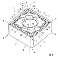
図1ないし図12は、本発明の一実施形態を示すものである。本実施形態において、インサート本体1は超硬合金等の硬質材料により形成されて、多角形板状、詳しくは四角形板状、より詳しくは菱形平板状をなしており、表裏の多角形面2とその周囲に配置される本実施形態では4つの側面3とを備えている。多角形面2がなす菱形の鋭角コーナ部Aの挟角は、本実施形態では80°とされている。これら表裏の多角形面2は、一方が切削に使用されるすくい面とされたときに、他方が刃先交換式バイト等の切削工具の工具本体に形成されたインサート取付座への着座面とされる。
1 to 12 show an embodiment of the present invention. In this embodiment, the
また、インサート本体1には、表裏の多角形面2がなす菱形の中心を通るインサート中心線Cを中心とした断面円形の取付孔4が、このインサート中心線C方向すなわちインサート厚さ方向(図3における上下方向)にインサート本体1を貫通するように形成されている。本実施形態では、インサート本体1が、このインサート中心線C回りに180°回転対称な形状に形成されるとともに、インサート厚さ方向に多角形面2に対向する平面視において多角形面2がなす菱形の対角線に沿った2つの平面に関してそれぞれ面対称形状とされている。さらに、インサート本体1は、これらの平面上に位置してインサート厚さ方向の中央でインサート中心線Cに直交する2つの直線に関してもそれぞれ180°回転対称形状とされ、すなわち表裏の多角形面2に関して表裏反転対称な形状に形成されている。
Further, the
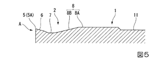
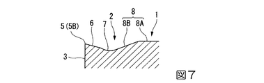
さらにまた、表裏の多角形面2と側面3との交差稜線部にはそれぞれ切刃5が形成されている。ここで、多角形面2の周回り方向に隣接する側面3同士の交差稜線部は凸曲面状に形成されており、これに伴い菱形をなす多角形面2のそれぞれ表裏に位置する各一対の鋭角コーナ部Aと鈍角コーナ部Bは上記平面視において図2および図4に示すように凸曲線状に形成される。本実施形態では、上記凸曲面は凸円筒面であって鋭角コーナ部Aと鈍角コーナ部Bは凸円弧状に形成され、切刃5は、このうち一対の鋭角コーナ部Aにコーナ刃5Aをそれぞれ備えるとともに、これらのコーナ刃5Aの両端から上記平面視に直線状に延びる1つのコーナ刃5Aに対して2つずつの主切刃5Bを備えている。
Furthermore, the
従って、側面3は、表裏の多角形面2の一方がすくい面とされたときの切刃5の逃げ面とされる。ここで、この逃げ面とされる側面3は、隣接する側面3同士の上記交差稜線部も含め、インサート厚さ方向に向けてインサート中心線Cに平行に延びるように形成されており、本実施形態の切削インサートは切刃5に逃げ角が付されていないネガティブタイプのインサートとされている。また、切刃5は、表裏の多角形面2のそれぞれにおいて、インサート厚さ方向に垂直な1つの平面上に位置している。
Therefore, the
さらに、多角形面2の外周縁部には、切刃5の内側に連なるポジすくい面6が形成されるとともに、このポジすくい面6のさらに内側にはブレーカ溝7が形成されている。これらポジすくい面6とブレーカ溝7は、それぞれ上記平面視における幅が一定とされて図2に示すように多角形面2の外周縁部を1周するように形成されており、同平面視におけるポジすくい面6の幅はブレーカ溝7の幅よりも大きくされている。
Further, a
ここで、本実施形態では、図5ないし図12に示すように、ポジすくい面6は多角形面2の内側に向かうに従い一定の傾斜角でインサート厚さ方向に後退傾斜するように形成されており、このポジすくい面6がインサート厚さ方向に垂直な平面に対してなす傾斜角、すなわち切刃5のすくい角は、例えば15°とされている。また、ブレーカ溝7は、その底面が切刃5に直交する断面においてポジすくい面6と鈍角に交差してインサート厚さ方向に凹む凹円弧等の凹曲線をなす凹曲面状に形成されている。
Here, in this embodiment, as shown in FIGS. 5 to 12, the
このように周縁部が形成された多角形面2の内側には、インサート厚さ方向に突出する突部8が切刃5と間隔をあけて形成されている。この突部8は、インサート厚さ方向に垂直な1つの平面上に配置される頂面8Aと、後述する凹部9の壁面9Bを除いた部分において各多角形面2からこの頂面8Aに向かうに従い該多角形面2の内側に向かうようにインサート厚さ方向に垂直な平面に対して一定の傾斜角で傾斜して延びる周面8Bとを備えている。
Thus, the
頂面8Aは、それぞれの多角形面2において、切刃5や鈍角コーナ部Bよりもインサート厚さ方向への突出高さが高くされ、インサート本体1において最も突出した位置に配置されている。また、周面8Bは、やはり後述する凹部9の壁面9Bに連なる部分を除いて凹曲面状をなすブレーカ溝7の底面に接するように形成されており、この周面8Bとブレーカ溝7の底面との接線は、上記平面視において図2に示すように切刃5と略一定の間隔をあけて延びている。
The
従って、上記平面視に突部8のコーナ刃5Aに臨む部分の周面8Bは、インサート厚さ方向に直交する断面がコーナ刃5Aの両端から延びる2つの主切刃5Bがなす角度と等しい挟角の凸V字状をなし、インサート厚さ方向に突出するに従い多角形面2の内側に向かうように傾斜して頂面8Aに達するように形成され、この部分の周面8Bと頂面8Aとの交差稜線も図4に示すように同様の凸V字状を呈することになる。ただし、これらの凸V字の凸端は凸円弧等の凸曲線によって丸みが付けられている。
Therefore, the
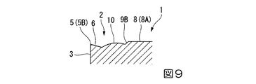
一方、上記平面視において、この突部8の周面8Bの主切刃5Bに臨む部分には、主切刃5Bに沿った方向にコーナ刃5Aから間隔をあけて凹部9が形成されている。この凹部9は、周面8Bに交差してインサート厚さ方向を向く底面9Aと、この底面9Aから突部8の頂面8Aに向かうに従い多角形面2の内側に向かうように傾斜して該頂面8Aに達する壁面9Bとを備えている。
On the other hand, in the plan view, a
凹部9の底面9Aは、本実施形態ではインサート厚さ方向に垂直な平面状とされ、そのインサート厚さ方向の高さは図8に示すように切刃5よりも高くされている。従って、底面9Aと突部8の周面8Bの交差稜線部は主切刃5Bと平行に延びている。さらに、壁面9Bは、コーナ刃5A側から主切刃5Bに沿った方向に反対側に向けて、上記平面視に図4に示すように主切刃5Bに対して多角形面2の内側に凹むように凹曲した後に主切刃5Bに近づくように形成されており、これに伴い底面9Aと壁面9Bとの交差稜線部も同平面視において主切刃5Bに対して凹む凹曲線状をなしている。
In this embodiment, the
また、本実施形態では図8に示すように、凹部9の壁面9Bがインサート厚さ方向に垂直な平面に対してなす傾斜角は、突部8の周面8Bが同じくインサート厚さ方向に垂直な平面に対してなす傾斜角よりも大きくされており、すなわち壁面9Bは周面8Bよりも急勾配でインサート厚さ方向に立ち上がるように形成されている。さらに、壁面9Bは、この凹部9から主切刃5Bに沿った方向にコーナ刃5Aとは反対側に向けて、上記平面視に主切刃5Bに向けて近づいた後に主切刃5Bと平行に延び、この主切刃5Bと平行に延びる部分ではブレーカ溝7の底面と交差するように形成されている。
In this embodiment, as shown in FIG. 8, the inclination angle formed by the
そして、このように壁面9Bが凹部9から主切刃5Bに向けて近づくように延びる部分には、表面が凸曲面状をなす突起10が形成されている。従って、この突起10は、上記平面視において主切刃5Bに沿った方向に凹部9に対してコーナ刃5Aとは反対側に位置するとともに、該凹部9よりも主切刃5Bに隣接するように形成されており、本実施形態では凹部9の壁面9Bから、突部8の周面8B、ブレーカ溝7の底面、およびポジすくい面6の内側部分に跨ってインサート厚さ方向に突出するように形成されている。
And the
また、この突起10のインサート厚さ方向への突出高さは、突部8の頂面8Aよりも低く、凹部9の底面9Aよりは高くされており、従って切刃5よりも高くされている。さらに、突起10の表面は本実施形態では凸球面状とされていて、その中心は、上記平面視において図4におけるWW断面の位置にあり、すなわち凹部9の底面9Aよりも主切刃5Bに沿った方向にコーナ刃5Aとは反対側に位置している。ただし、突起10のコーナ刃5A側の一部は、主切刃5Bに沿った方向においては凹部9の底面9Aとオーバーラップするように配置されている。
Further, the protrusion height of the
さらに、上記平面視において、この突起10が形成される壁面9Bが主切刃5Bに向けて近づく部分では、壁面9Bが交差する突部8の頂面8Aも図4に示すように主切刃5Bに向けて近づくことになり、さらに突起10よりもコーナ刃5Aとは反対側で壁面9Bが主切刃5Bと平行に延びる部分では、壁面9Bと頂面8Aとの交差稜線も主切刃5Bと平行に延びることになる。従って、同平面視における頂面8Aと主切刃5Bとの間隔、すなわち頂面8Aと壁面9Bまたは周面8Bとの交差稜線と主切刃5Bとの間隔は、突起10よりもコーナ刃5Aとは反対側の部分が、突起10よりもコーナ刃5A側の部分よりも小さくされている。
Furthermore, in the plan view, at the portion where the
なお、壁面9Bは、こうして上記平面視に主切刃5Bと平行に延びた部分から多角形面2の内側に延び、主切刃5Bに沿った方向におけるコーナ刃5Aとは反対側の突部8の終端部をなすように形成されている。さらに、この終端部から多角形面2の内側で壁面9Bは、インサート厚さ方向に凹部9の底面9Aと同じ高さで突部8と取付孔4との間に形成された平面部11に交差して、上記平面視においてコーナ刃5Aの二等分線側に向かうように延びている。ただし、壁面9Bがこの二等分線に至る途中には、上記平面視において該二等分線に略平行に取付孔4側に突出する角(つの)部が頂面8Aに形成されるように壁面9Bが曲折させられている。
The
一方、本実施形態では、表裏の多角形面2がなす菱形面の鈍角コーナ部Bにも、それぞれ突部8と同様の頂面12Aと周面12Bとを有する突部12が切刃5と間隔をあけて形成されており、この突部12の頂面12Aのインサート厚さ方向における突出高さは各多角形面2において突部8の頂面8Aの突出高さと等しくされるとともに、周面12Bは各主切刃5Bに沿った部分において周面8Bの延長面上に形成されている。また、この鈍角コーナ部B側の突部12は、本実施形態では鋭角コーナ部A側の突部8とも間隔をあけて形成されるとともに、取付孔4との間には平面部11を介することなくその開口部に頂面12Aが交差している。
On the other hand, in the present embodiment, the
さらに、この突部12の周面12Bにも、突部8の周面8Bに形成された凹部9と同様の凹部13が形成されるとともに、この凹部13に対して、上記平面視において主切刃5Bに沿った方向に鈍角コーナ部Bとは反対側で、主切刃5Bに隣接した位置には、突起10と同様の突起14が形成されている。すなわち、凹部13の底面13Aは凹部9の底面9Aおよび平面部11の延長面上にあり、また凹部13の壁面13Bがインサート厚さ方向に垂直な平面に対してなす傾斜角は壁面9Bと等しくされている。また、突起14の表面は凸球面状で、その半径と中心の上記平面視における主切刃5Bからの距離とは突起10と等しくされている。従って、本実施形態では、1つの主切刃5Bに対して2つの突起10、14が形成されることになる。
Further, a
このように構成された切削インサートが取り付けられる上記インサート取付座は、上述の刃先交換式バイトのような切削工具の工具本体先端部に形成された凹所であり、多角形面2と合同または相似形の平坦な底面と、本実施形態のようなネガティブタイプのインサートを取り付ける場合にはこの底面から垂直に立ち上がる2つの壁面とを有している。壁面同士は、インサート本体1の多角形面2の鋭角コーナ部Aにおける挟角と等しい角度で交差している。さらに、底面の中央部には、レバーロック等のインサート取付機構のピンが突出している。
The insert mounting seat to which the cutting insert configured in this way is attached is a recess formed at the tip of the tool body of a cutting tool such as the above-described blade edge replaceable bite, and is congruent or similar to the
このようなインサート取付座に、上記構成の切削インサートは、上述のように表裏の多角形面2の一方がすくい面とされたときに他方が着座面とされ、上記ピンが取付孔4に挿入されながらこの着座面とされた多角形面2が上記底面に対向して着座させられる。次いで、上記インサート取付機構によってピンが壁面同士の交差角の二等分線方向に引き込まれることにより取付孔4内周面が押圧され、鋭角コーナ部Aに交差する2つの側面3が壁面に当接させられてインサート本体1が着脱可能に取り付けられる。
In such an insert mounting seat, the cutting insert having the above-described configuration is such that when one of the front and back
このとき、1つの多角形面2においては、2つの鋭角コーナ部A側の突部8の頂面8Aと、本実施形態では2つの鈍角コーナ部B側の突部12の頂面12Aとが、インサート厚さ方向に最も突出して1つの平面上に位置しているため、着座面とされる他方の多角形面2においては、これらの頂面8A、12Aがインサート取付座の底面に密着する。また、反対側のすくい面とされた一方の多角形面2においては、切刃5のうち、工具本体先端部に突出する鋭角コーナ部Aに形成されたコーナ刃5A、およびこのコーナ刃5Aの一端に連なる主切刃5Bが切り込み量に応じて切削に使用される。
At this time, in one
ここで、まず上記構成の切削インサートでは、すくい面とされた一方の多角形面2において、突部8および突起10が切刃5と間隔をあけて形成されていて、特許文献1、2に記載された切削インサートのように多角形面の中央面とランド面とがインサート厚さ方向に同じ高さの連結部によって連結されたりしていない。このため、切刃5によって生成されて多角形面2上に流れ出た切屑がこのような連結部に遮られることにより行き場を無くして詰まりを生じるようなことがない。
First, in the cutting insert having the above-described configuration, the
また、本実施形態では、切刃5に連なるポジすくい面6が多角形面2の内側に向かうに従いインサート厚さ方向に後退傾斜するように形成されて、切刃5に正のすくい角が与えられており、このすくい角が15°と比較的大きくされているので、切刃5に鋭い切れ味を確保して切削抵抗の低減を図ることができる。このため、耐熱合金のような熱伝導率の低い金属材料の切削加工のように切削熱が切屑とともに除去され難い場合でも切削熱の発生を抑えることができ、インサート本体1の切刃5周辺や被削材の切削部位に切削熱が集中して損傷が生じたりするのを防ぐことが可能となる。
In this embodiment, the
そして、このように切刃5のすくい角を正角側に大きく設定した場合に、切屑が万一すくい面とされた一方の多角形面2側で十分に処理されずに弧を描いて着座面とされた他方の多角形面2側に延びたとしても、上記構成の切削インサートでは、この他方の多角形面2にも突起10が形成されており、この突起10はインサート厚さ方向への突出高さが、突部8の頂面8Aよりは低いものの切刃5よりは高くなるように形成されているので、他方の多角形面2とインサート取付座の底面との間の隙間を小さくすることができる。
Then, when the rake angle of the
このため、上記構成の切削インサートによれば、このような切屑が上記隙間から侵入することによって着座面とされた他方の多角形面2が打撃されて欠け等が生じるのを防ぐことができ、インサート本体1を表裏反転させてインサート取付座に取り付け直すことにより他方の多角形面2をすくい面としたときに切削加工に支障が生じたりするのを防止することができる。また、本実施形態では、鈍角コーナ部B側にも突起14が形成されているので、このような切屑の侵入をさらに確実に防止することができる。
For this reason, according to the cutting insert having the above-described configuration, it is possible to prevent the chip from being struck by the other
さらに、本実施形態では、上記平面視における頂面8Aと主切刃5Bとの間隔は、突起10よりもコーナ刃5Aとは反対側の部分が、突起10よりもコーナ刃5A側の部分よりも小さくされている。従って、この突起10よりもコーナ刃5Aとは反対側の部分では、突部8の頂面8Aを切刃5(主切刃5B)により近づけて配置することができ、着座面とされた他方の多角形面2において着座安定性の向上を図って一層安定した切削加工を行うことが可能となる。特に、本実施形態のように切刃5のすくい角が正角側に比較的大きく設定されている場合には、刃先交換式バイトの工具本体の振動によって切刃5に欠けが生じやすいため、着座安定性が向上することは極めて重要である。
Further, in the present embodiment, the distance between the
そして、このようにコーナ刃とは反対側の部分で突部8を切刃5に近づけたとしても、上記構成の切削インサートにおいてはこの部分に突起10が形成されており、上述のようにこの突起10を突部8よりもさらに切刃5に近接して配置することにより、切屑が十分に処理されずに他方の多角形面2側に回り込んだとしても、インサート取付座の底面との間の隙間に侵入して突部8が打撃されるのは避けることができる。このため、着座安定性を向上させつつ、インサート本体1の損傷は確実に防止することができる。
Even when the
一方、この突起10は、上記平面視において主切刃5Bに沿った方向には上記凹部9に対してコーナ刃5Aとは反対側に位置していて、この凹部9の幅の分だけコーナ刃5Aとは大きな間隔をあけて配置されている。このため、耐熱合金のような金属材料の中切削の際に切削速度が小さくても、生成された切屑が突起10に摺接して凝着を生じたりすることはない。また、中切削の際に切屑が摺接する突部8の周面8Bには凹部9が形成されていて切屑の摺接面積が小さくされているので、切屑が周面8Bに凝着するのも防ぐことができ、このような切屑の凝着によって切れ味が低下したりインサート本体1が異常損傷したりするのを防ぐことができる。
On the other hand, the
さらに、このような中切削において送り量が小さい場合に生成される薄肉の切屑は、凹部9の底面9Aとブレーカ溝7との間の幅狭とされた突部8の周面8Bに摺接して抵抗を受けることによりカールされて分断処理される。従って、このような低送りの際に薄肉の切屑が受ける抵抗が必要以上に大きくなるのを防ぐことができ、安定した切屑処理を図ることができる。これは、倣い切削において切り込み量が中切削程度になったときに送り量が小さい場合でも同様である。
Furthermore, the thin chips generated when the feed amount is small in such a medium cutting slidably contact the
また、中切削や倣い切削において切り込み量が中切削程度になったときに送り量が大きい場合に生成される厚肉の切屑は、この幅狭の周面8Bを乗り越えて凹部9の壁面9Bに摺接することにより処理される。従って、切屑が流出するスペースを大きく確保して、切屑詰まりが生じるのを防ぐことができるので、上記構成の切削インサートによれば、中切削や倣い切削において低送りから高送りに亙り、安定した切屑処理を図って円滑な切削加工を行うことが可能となる。
In addition, the thick chips generated when the feed amount is large when the cutting amount becomes about the middle cutting in medium cutting or copying cutting, get over the narrow
しかも、本実施形態では、こうして高送りの際に切屑が摺接する壁面9Bがインサート厚さ方向に垂直な平面に対してなす傾斜角が、低送りの際に切屑が摺接する周面8Bがインサート厚さ方向に垂直な平面に対してなす傾斜角よりも大きくされており、この高送りの際の肉厚の切屑にも十分な抵抗を与えて効率的に処理することができる。また、これとは逆に低送りの際の薄肉の切屑には必要以上の抵抗が与えられるのを一層確実に防いで、さらに安定した切屑処理を図ることができる。
In addition, in this embodiment, the inclined surface formed by the
さらに、このような中切削よりも切り込み量が大きい粗切削の場合には、上記凹部9に対してコーナ刃5Aとは反対側に位置するとともに主切刃5B側に隣接した突起10に、切屑が摺接することになる。そして、この突起10は表面が凸曲面状であって、特に本実施形態では凸球面状であるので、切屑との接触面積を小さく抑えて切屑がベタ当たりするのを防ぐことができる。
Further, in the case of rough cutting with a cutting depth larger than that of the middle cutting, chips are formed on the
従って、このような切屑のベタ当たりによって切削抵抗が増大するのを防いで、これに伴い切削熱の発生も抑えることができるので、上記構成の切削インサートによれば、耐熱合金のような金属材料の切削において、さらに確実に切削熱によるインサート本体1の損傷を防ぐとともに、粗切削に至っても安定した切屑処理を図ることができる。そして、このように粗切削の安定した切屑処理や、上述したように中切削や倣い切削でも安定した切屑処理が図られることにより、すくい面とされた一方の多角形面2において切屑が十分処理されずに着座面とされた他方の多角形面2側に回り込むおそれも低減して、このような切屑によるインサート本体1の損傷も一層確実に防止することができる。
Therefore, it is possible to prevent the cutting resistance from increasing due to such solid chips, and to suppress the generation of cutting heat. Accordingly, according to the cutting insert configured as described above, a metal material such as a heat-resistant alloy can be used. In this cutting, damage to the
なお、このように突起10の表面が凸球面状である場合に、突起10を凹部9よりもコーナ刃5Aとは反対側に配置するには、本実施形態のように上記平面視における突起10の中心が凹部9の底面9Aよりもコーナ刃5Aとは反対側に位置していればよい。また、本実施形態では、切刃5のすくい角が15°で一定とされているが、コーナ刃5Aから鈍角コーナ部Bに向けてすくい角が段階的または連続的に小さくなるようにされていてもよく、例えば主切刃5Bに沿った方向において突起10が形成された部分ですくい角が漸次小さくなるようにされて、この部分よりもコーナ刃5A側では正角側に大きな一定のすくい角とされ、この部分よりもコーナ刃5Aとは反対側(鈍角コーナ部B側)では0°または小さな一定のすくい角とされていてもよい。
When the surface of the
さらに、本実施形態では、鋭角コーナ部Aの挟角が80°の菱形板状のインサート本体1を備えた切削インサートに本発明を適用した場合について説明したが、挟角が80°以外の菱形板状のインサート本体1を備えた切削インサートに本発明を適用することも可能である。さらに、菱形以外の正方形や長方形のような四角形、あるいは正三角形、もしくは等辺不等角六角形等の他の多角形板状のインサート本体を備えた切削インサートに本発明を適用することも可能である。
Furthermore, although this embodiment demonstrated the case where this invention was applied to the cutting insert provided with the rhombus plate-shaped insert
また、同じく本実施形態では、コーナ刃5Aの両端から主切刃5Bが延びていて、インサート本体1が上記平面視において多角形面2がなす菱形の対角線(コーナ刃5Aの二等分線)に沿った平面に関して面対称形状とされた、いわゆる勝手無しの切削インサートに本発明を適用した場合について説明したが、コーナ刃5Aの一端からのみ主切刃5Bが延びていて、インサート本体1が上記平面に関して面対称とされていない、いわゆる勝手付きの切削インサートに本発明を適用することも可能である。さらに、本実施形態では突起10の表面が凸球面状をなしているが、凸曲面状であれば楕円球面状や長円球面状であったり、涙滴形であったりしてもよい。
Similarly, in this embodiment, the
1 インサート本体
2 多角形面
3 側面
4 取付孔
5 切刃
5A コーナ刃
5B 主切刃
6 ポジすくい面
7 ブレーカ溝
8 突部
8A 突部8の頂面
8B 突部8の周面
9 凹部
9A 凹部9の底面
9B 凹部9の壁面
10 突起
A 鋭角コーナ部
B 鈍角コーナ部
C インサート中心線
DESCRIPTION OF
Claims (4)
上記多角形面のそれぞれと上記側面との交差稜線部には切刃が形成され、
上記切刃は、上記インサート本体の表裏に位置する上記多角形面の少なくとも1つずつのコーナ部に配置されて該多角形面に対向するインサート厚さ方向から見た平面視に凸曲線状をなすコーナ刃と、このコーナ刃の少なくとも一端から延びる主切刃とを備え、
上記多角形面は互いに、一方の多角形面がすくい面とされたときに他方の多角形面が着座面とされる切削インサートであって、
上記多角形面にはそれぞれ、該多角形面から上記インサート厚さ方向に突出する突部と突起とが上記切刃と間隔をあけて形成されており、
上記突部は、上記多角形面のそれぞれにおいて、該多角形面の上記切刃よりも突出して上記インサート厚さ方向に垂直な1つの平面上に配置される頂面と、各多角形面から上記頂面に向かうに従い該多角形面の内側に向かうように傾斜する周面とを備え、
上記平面視において上記周面の上記主切刃に臨む部分には、該周面に交差して上記インサート厚さ方向を向く底面と、この底面から上記頂面に向かうに従い上記多角形面の内側に向かうように傾斜して該頂面に達する壁面とを備えた凹部が、上記平面視において上記主切刃に沿った方向に上記コーナ刃から間隔をあけて形成され、
この凹部の上記壁面は、上記主切刃に沿った方向において上記コーナ刃側から反対側に向けて、上記平面視に上記主切刃に対して上記多角形面の内側に凹むように凹曲した後に上記主切刃に近づくように形成されており、
上記突起は、上記壁面が上記主切刃に向けて近づくように延びる部分に形成され、表面が凸曲面状であって、上記多角形面のそれぞれにおいて、上記インサート厚さ方向への突出高さが上記突部の頂面より低く、上記切刃よりは高くされており、上記平面視において、上記主切刃に沿った方向に上記凹部に対して上記コーナ刃とは反対側に位置しているとともに、上記凹部よりも上記主切刃に隣接していることを特徴とする切削インサート。 A polygonal plate-like insert body having front and back polygonal surfaces and side surfaces arranged around these polygonal surfaces;
Cutting edges are formed at the intersection ridges between each of the polygonal surfaces and the side surfaces,
The cutting blade is arranged in at least one corner portion of the polygonal surface located on the front and back of the insert body and has a convex curve shape in a plan view as viewed from the insert thickness direction facing the polygonal surface. A corner blade formed, and a main cutting blade extending from at least one end of the corner blade,
The polygonal surfaces are cutting inserts in which when one polygonal surface is a rake surface, the other polygonal surface is a seating surface,
Each of the polygonal surfaces is formed with a protrusion and a protrusion protruding from the polygonal surface in the insert thickness direction with a gap from the cutting edge.
In each of the polygonal surfaces, the protrusion protrudes from the cutting edge of the polygonal surface and is arranged on one plane perpendicular to the insert thickness direction, and each polygonal surface And a peripheral surface that inclines toward the inside of the polygonal surface toward the top surface,
A portion of the peripheral surface facing the main cutting edge in the plan view includes a bottom surface that intersects the peripheral surface and faces the insert thickness direction, and an inner side of the polygonal surface from the bottom surface toward the top surface. A concave portion provided with a wall surface that is inclined so as to reach the top surface is formed at a distance from the corner blade in a direction along the main cutting edge in the plan view,
The wall surface of the recess is concavely curved so as to be recessed inward of the polygonal surface with respect to the main cutting edge in the plan view from the corner blade side toward the opposite side in the direction along the main cutting edge. Is formed to approach the main cutting edge after
The protrusion is formed in a portion extending so that the wall surface approaches the main cutting edge, the surface is a convex curved surface, and the protrusion height in the insert thickness direction in each of the polygonal surfaces. Is lower than the top surface of the protrusion and higher than the cutting edge, and is located on the opposite side of the corner blade with respect to the recess in the direction along the main cutting edge in the plan view. And a cutting insert that is adjacent to the main cutting edge rather than the recess.
Priority Applications (1)
| Application Number | Priority Date | Filing Date | Title |
|---|---|---|---|
| JP2013125832A JP6251988B2 (en) | 2013-06-14 | 2013-06-14 | Cutting insert |
Applications Claiming Priority (1)
| Application Number | Priority Date | Filing Date | Title |
|---|---|---|---|
| JP2013125832A JP6251988B2 (en) | 2013-06-14 | 2013-06-14 | Cutting insert |
Publications (2)
| Publication Number | Publication Date |
|---|---|
| JP2015000447A JP2015000447A (en) | 2015-01-05 |
| JP6251988B2 true JP6251988B2 (en) | 2017-12-27 |
Family
ID=52295289
Family Applications (1)
| Application Number | Title | Priority Date | Filing Date |
|---|---|---|---|
| JP2013125832A Active JP6251988B2 (en) | 2013-06-14 | 2013-06-14 | Cutting insert |
Country Status (1)
| Country | Link |
|---|---|
| JP (1) | JP6251988B2 (en) |
Families Citing this family (2)
| Publication number | Priority date | Publication date | Assignee | Title |
|---|---|---|---|---|
| US11027339B2 (en) * | 2017-02-27 | 2021-06-08 | Kyocera Corporation | Cutting insert, cutting tool, and method of manufacturing machined product |
| US10710167B2 (en) * | 2017-08-02 | 2020-07-14 | Iscar, Ltd. | Negative finish turning insert with chip forming arrangement |
Family Cites Families (4)
| Publication number | Priority date | Publication date | Assignee | Title |
|---|---|---|---|---|
| JPS4932280A (en) * | 1972-07-22 | 1974-03-23 | ||
| JPH04115808A (en) * | 1990-09-05 | 1992-04-16 | Dijet Ind Co Ltd | Throw-away chip |
| JP3812473B2 (en) * | 2001-11-20 | 2006-08-23 | 三菱マテリアル株式会社 | Throwaway tip |
| JP5158490B2 (en) * | 2008-03-06 | 2013-03-06 | 住友電工ハードメタル株式会社 | Replaceable cutting edge |
-
2013
- 2013-06-14 JP JP2013125832A patent/JP6251988B2/en active Active
Also Published As
| Publication number | Publication date |
|---|---|
| JP2015000447A (en) | 2015-01-05 |
Similar Documents
| Publication | Publication Date | Title |
|---|---|---|
| JP5024483B2 (en) | Cutting insert | |
| EP3088111B1 (en) | Drill insert and indexable drill | |
| JP5158490B2 (en) | Replaceable cutting edge | |
| JP5853613B2 (en) | Cutting insert | |
| JP5895456B2 (en) | Cutting insert | |
| WO2017122715A1 (en) | Cutting insert and blade-tip-replaceable cutting tool | |
| JP6213460B2 (en) | Cutting insert | |
| JP2010069614A (en) | Cutting insert | |
| JPWO2010150696A1 (en) | Cutting insert | |
| JP2011115896A (en) | Cutting insert | |
| JP4923569B2 (en) | Throwaway tip | |
| JP6251988B2 (en) | Cutting insert | |
| JP7171605B2 (en) | Cutting insert with split cutting edge with front and rear component cutting edges | |
| JP2015000446A (en) | Cutting insert | |
| JP2007007736A (en) | Throwaway chip | |
| JP5589425B2 (en) | Cutting inserts for grooving and parting off | |
| JP2008073827A (en) | Cutting insert | |
| JP5365285B2 (en) | Cutting insert | |
| JP7484355B2 (en) | Cutting Insert | |
| JP2007290057A (en) | Ultra-high pressure sintered body cutting tool | |
| JP2008302433A (en) | Throw-away tip for cutting | |
| JP4127334B2 (en) | Throwaway tip | |
| JP7473835B2 (en) | Cutting inserts and indexable cutting tools | |
| JP7260747B2 (en) | Cutting inserts, indexable ball end mills | |
| JP2014221500A (en) | Cutting insert |
Legal Events
| Date | Code | Title | Description |
|---|---|---|---|
| A621 | Written request for application examination |
Free format text: JAPANESE INTERMEDIATE CODE: A621 Effective date: 20160331 |
|
| A977 | Report on retrieval |
Free format text: JAPANESE INTERMEDIATE CODE: A971007 Effective date: 20170127 |
|
| A131 | Notification of reasons for refusal |
Free format text: JAPANESE INTERMEDIATE CODE: A131 Effective date: 20170131 |
|
| A521 | Written amendment |
Free format text: JAPANESE INTERMEDIATE CODE: A523 Effective date: 20170327 |
|
| A131 | Notification of reasons for refusal |
Free format text: JAPANESE INTERMEDIATE CODE: A131 Effective date: 20170829 |
|
| A521 | Written amendment |
Free format text: JAPANESE INTERMEDIATE CODE: A523 Effective date: 20171017 |
|
| TRDD | Decision of grant or rejection written | ||
| A01 | Written decision to grant a patent or to grant a registration (utility model) |
Free format text: JAPANESE INTERMEDIATE CODE: A01 Effective date: 20171031 |
|
| A61 | First payment of annual fees (during grant procedure) |
Free format text: JAPANESE INTERMEDIATE CODE: A61 Effective date: 20171113 |
|
| R150 | Certificate of patent or registration of utility model |
Ref document number: 6251988 Country of ref document: JP Free format text: JAPANESE INTERMEDIATE CODE: R150 |