EP3087362B1 - Digitaler temperaturfühler mit integriertem zeitgeber und burstbetrieb - Google Patents
Digitaler temperaturfühler mit integriertem zeitgeber und burstbetrieb Download PDFInfo
- Publication number
- EP3087362B1 EP3087362B1 EP14821026.3A EP14821026A EP3087362B1 EP 3087362 B1 EP3087362 B1 EP 3087362B1 EP 14821026 A EP14821026 A EP 14821026A EP 3087362 B1 EP3087362 B1 EP 3087362B1
- Authority
- EP
- European Patent Office
- Prior art keywords
- temperature sensor
- sensor device
- digital
- analog
- integrated temperature
- Prior art date
- Legal status (The legal status is an assumption and is not a legal conclusion. Google has not performed a legal analysis and makes no representation as to the accuracy of the status listed.)
- Active
Links
Images
Classifications
-
- G—PHYSICS
- G01—MEASURING; TESTING
- G01K—MEASURING TEMPERATURE; MEASURING QUANTITY OF HEAT; THERMALLY-SENSITIVE ELEMENTS NOT OTHERWISE PROVIDED FOR
- G01K1/00—Details of thermometers not specially adapted for particular types of thermometer
-
- G—PHYSICS
- G01—MEASURING; TESTING
- G01K—MEASURING TEMPERATURE; MEASURING QUANTITY OF HEAT; THERMALLY-SENSITIVE ELEMENTS NOT OTHERWISE PROVIDED FOR
- G01K7/00—Measuring temperature based on the use of electric or magnetic elements directly sensitive to heat ; Power supply therefor, e.g. using thermoelectric elements
- G01K7/01—Measuring temperature based on the use of electric or magnetic elements directly sensitive to heat ; Power supply therefor, e.g. using thermoelectric elements using semiconducting elements having PN junctions
-
- G—PHYSICS
- G01—MEASURING; TESTING
- G01K—MEASURING TEMPERATURE; MEASURING QUANTITY OF HEAT; THERMALLY-SENSITIVE ELEMENTS NOT OTHERWISE PROVIDED FOR
- G01K1/00—Details of thermometers not specially adapted for particular types of thermometer
- G01K1/02—Means for indicating or recording specially adapted for thermometers
- G01K1/028—Means for indicating or recording specially adapted for thermometers arrangements for numerical indication
-
- G—PHYSICS
- G01—MEASURING; TESTING
- G01K—MEASURING TEMPERATURE; MEASURING QUANTITY OF HEAT; THERMALLY-SENSITIVE ELEMENTS NOT OTHERWISE PROVIDED FOR
- G01K7/00—Measuring temperature based on the use of electric or magnetic elements directly sensitive to heat ; Power supply therefor, e.g. using thermoelectric elements
- G01K7/42—Circuits effecting compensation of thermal inertia; Circuits for predicting the stationary value of a temperature
-
- G—PHYSICS
- G01—MEASURING; TESTING
- G01K—MEASURING TEMPERATURE; MEASURING QUANTITY OF HEAT; THERMALLY-SENSITIVE ELEMENTS NOT OTHERWISE PROVIDED FOR
- G01K2219/00—Thermometers with dedicated analog to digital converters
Definitions
- the present disclosure relates to digital temperature sensor devices, in particular to a digital temperature sensor with advanced features.
- a variety of integrated semiconductor temperature sensor exists. Such sensors are available in housings having a low number of pins and may provide either an analog or a digital interface. Analog temperature sensors typically output a voltage that is proportional to the measured temperature while digital temperature sensors provide for a digital interface that is designed to encode the temperature value into a digital value and provide these to a processor, for example using a serial interface. To keep the number of pins low, these digital temperature sensors often use a single wire interface. However, other devices may use interfaces with more than one wire. While such digital temperature sensors are convenient and can be used in many applications, certain applications may in addition require features. Hence, there exists a need for improved digital temperature sensors.
- US Patent Application Publication US2001/0021217 discloses methods and apparatus for thermal management of an integrated circuit die.
- US Patent Application Publication US2004/0024561 discloses a method and apparatus for temperature throttling the access frequency of an integrated circuit.
- WO/19293 A2 discloses an integrated chip with two temperature sensors, wherein power is regulated so that sleep cycles follow corresponding measurement cycles.
- an integrated temperature sensor device as in claim 1 is provided.
- a method for operating an integrated temperature sensor device according to claim 11 is provided.
- a temperature sensing device with a user selectable timer interval allows to take a burst of temperature readings and monitor temperature at the preset intervals.
- the stand-alone temperature sensor device with a very fast temperature conversion rate and low operating current makes it ideal for this type of applications where typical functions such as time management can be off loaded from the controller to save more power.
- timer intervals are managed by a microcontroller coupled with a separate temperature sensor device, and at preset intervals the controller samples the temperature from the sensor.
- the controller In low power applications where the controller is in low power or sleep mode to save battery life, the controller will have to wake up from sleep mode and measure temperature at preset intervals. This activity consumes power.
- the sensor can be programmed with preset intervals to measure a burst of temperature samples and monitor the user set temperature alert thresholds so the microcontroller does not have to consume power to do so.
- such a digital temperature sensor may further comprise a digital filter feature which enables a user to control the temperature sensor sensitivity.
- a digital filter feature which enables a user to control the temperature sensor sensitivity.
- filters may be implemented. The lowest filter setting enables the user to detect fast thermal transients, and the highest filter setting reduces the sensor sensitivity, outputting gradual changes in temperature.
- the temperature sensor may be configurable, for example comprising a configuration register which can be configured through a serial interface of the device.
- such a low power and digital temperature sensor may output temperature data at faster speeds than conventional devices, for example at 5 millisecond intervals (typically), or 200 times per second, for a high resolution temperature data. This rate is approximately 25 times faster than the speed of a conventional temperature sensor. Due to this high speed conversion rate, the device spends less time in the temperature conversion mode which saves the overall operating power when it is used in conjunction with the low power or shutdown mode. However, due to the fast temperature conversion, fast thermal transients may be detected from the application and the device may output false temperature alerts.
- the solution is to implement an integrated digital filter with the options for the user to adjust the filter coefficient or the filter strength.
- a microcontroller In conventional applications, if the application needs a digital filter, a microcontroller is used to process and filter the temperature data. According to various embodiments, the microcontroller consumes significantly higher operating current or power than the temperature sensor. Therefore, this integrated feature eliminates the associated processing requirements of a microcontroller and makes the digital temperature sensor according to various embodiments ideal for extremely low power applications.
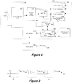
- a temperature sensor 100 there can be several functional blocks to a temperature sensor 100 according to various embodiments as shown in Fig. 1 : the sensor proper 110 and the associated conditioning circuit 120, an analog to digital converter 130, and user programmable registers 140.
- a diode 110 can be used in this example to measure temperature and the sensor conditioning circuit 120 is used to bias the sensor diode 110 and scale the diode voltage to measurable levels.
- other type of sensors and if necessary conditioning circuits may be used.
- the temperature sensor provides for an analog signal, such as a voltage or a current that can easily be converted into a temperature value.
- the analog value may be proportional to the temperature or may have a known linear or non-linear relationship. For example, tables stored in memory may be used within the sensor device to retrieve a temperature value corresponding to the analog value.
- the analog to digital converter 130 is used to convert the ambient temperature data in digital format.
- the digital temperature data is available to the user in the user Ambient Temperature data register 142 and according to one operating mode may be directly written into register 142.
- the output values from the analog-to-digital converter 130 may be forwarded to the control unit which may include a simple arithmetic logic unit 165.
- This unit may be configured to calculate an average value for a plurality of temperature values received during a temperature burst measurement cycle. A calculated average temperature may then be stored in an associated register 148.
- the output values of a digital filter block 150 may be forwarded to the control unit and an average of the filtered temperature values may be calculated by the ALU 165 and stored in either register 148, 146 or another register.
- the temperature sensor may further be designed to be configurable through the registers 140.
- the digital filter block 150 can be provided, wherein the ambient temperature digital data is passed through the filter engine of the digital filter 150.
- the filter coefficients or filter strength can be adjusted by the user using the Filter Coefficients data register 144.
- the filtered data is then available in the Filtered Temperature Register 146.
- control logic of the temperature sensor may furthermore comprises a timer control circuit 190 coupled with control unit 160 as shown in Figure 1 .
- Fig. 3 shows such a control unit 190 in more detail. It may include a timer 192 and associated comparator 194 for comparing a timer value to a predefined number, for example a number stored in one of the configuration/control registers 144.
- Figures 1 and 3 only show a single configuration register 144. However, the device may have a plurality of respective configuration registers 144 that can be accessed through the serial interface 170 if necessary.
- a counter 196 may be implemented that may be configured to load a preset value from registers 144 and count down to 0.
- a power supply and control unit 195 may be provided which may be coupled with control unit 160.
- the power supply control unit 195 may include circuitry for providing all necessary internal supply voltages, reference voltages etc., and may further provide respective distribution of these voltages to respective circuits or units of the device.
- the control unit 160 may be configured to control unit 195 to switch the entire device into a shut-down mode, such as for example a sleep mode, during which only the respective timer for determining a period TSHDN_TMR and associated logic is operable as will be explained in more detail below.
- the power supply and control unit is thus configured to shut down supply voltages for all units that do not need to operate during a sleep mode and to provide respective voltages to these units once the sleep-mode has been terminated.
- the device only requires a minimum of power.
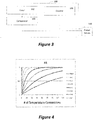
- a timing diagram in Figure 2 indicates a temperature sampling burst operating mode using such a timer control circuit 190 as shown in Fig. 3 in more detail.
- parameter 'm' represents the number of burst temperature samples per burst period, wherein for example such a value may be user programmable through register 144 as shown in Figure 3 , for example, can be set from 1 to 128 samples.
- the counter 196 in the timer and control circuit 190 is configured for counting down the number 'm' of temperature values per period. The time period ⁇ t between sequential samplings may be determined by the speed of the analog-to-digital converter 130.
- a second value T SHDN_ TMR refers to a low power or shutdown mode time (with timer on). Again this value can be user programmable, for example set from 0.5s to 128s in a respective control register 144.
- the timer 192 of the timer and control unit 190 may be used to measure this parameter and compare it with comparator 194 to generate respective internal signals and if necessary external one or more signals through the serial interface 170.
- each vertical line in Figure 2 indicates a temperature sample and the letter 'm' indicates the number of samples which is set by the user using an associated user programmable data register 144.
- the T SHDN_ TMR value is the user programmed timer interval value which according to some embodiments can range from, e.g., 0.5 second to 128 seconds. However, other ranges may be implemented.
- the timer can operate in a simple decrement mode and count down to 0 to determine the respective shut-down/sleep mode time period. As indicated in the timing diagram of Fig. 2 , at the timer intervals the device takes m number of temperature bursts and may also monitor the temperature alert limits.
- each measured value can be compared, for example, by a comparator 167 within control unit 160, with a threshold value to generate an alert through interface 170.
- the threshold value may be stored in yet another register 144.
- the m temperature values can be automatically averaged as explained above by control unit 160 to produce an average temperature value which can then be stored, e.g., in register 148. Then, the averaged value can be compared by control unit 160 with a threshold value.
- the alert can be an interrupt signal fed from the temperature device to the microcontroller through a dedicated interrupt line 185 or alternatively a signal sent through serial interface 170.
- a microcontroller may not process any of the measured values until an interrupt signal or respective message has been received.
- the microcontroller may receive a signal and read the measured value to determine what actions have to follow.
- Multiple threshold may be implemented such as minimum and maximum values and respective comparators may be implemented in control unit 160 to generate one or more wake-up signals.
- the temperature sensor device 100 may automatically output each temperature value during a burst or an averaged temperate value at the end of a burst, or an averaged filtered temperature value, etc. via the interface.
- the device may allow under program control to operate in any of the disclosed operating modes.
- the sensor 100 filters temperature data to prevent false alerts and is about 25x faster than a conventional device, wherein its short operating time saves power.
- the fast conversion time increases sensitivity to the measuring system thermal noise.
- the added digital filter 150 with user programmable filter strength allows the device to manage thermal data within the temperature sensor so the microcontroller doesn't have to wake-up to perform this task.
- Table 1 shows an example of a digital filter to be used in a temperature sensor 100 as shown in Fig. 1 according to various embodiments.
- the values stored in an associated one of the control register 144 are used as an index to select one of a plurality of predefined filter coefficients.
- Other bits could be used according to various embodiments and the above mentioned specific bits are merely an example.
- a user merely needs to store a selection number to activate a specific filter function. If the index is equal to 0, then the entire filter will be disabled.
- other embodiments may use a different configuration process.
- the filter may have a plurality of variable parameters and a user may directly program these parameters into various registers. While this option provides a user more control over the filter, it also would involve a more complicated set-up procedure.
- More than one type of filter or other additional functions can be implemented and a user may have the opportunity to select one of the plurality of filters or post processing routines.
- a digital temperature sensor device may have additional averaging routines and associated registers that store selectable or pre-defined averaging numbers.
- Various averaging routines could be implemented that calculate a mean or geometric average and optional other statistical values.
- the filter is an infinite impulse response low pass filter.
- eight different filter coefficient settings may be provided. Three bits of a control register 144 may provide for these options as explained above. However, more or less options may be provided according to other embodiments.
- the control register may have more bits that can be used for other configurations such as operating mode as discussed above. As can be seen in Fig 4 , if the filter coefficient is set to zero, no filter function will be applied. Thus this setting can be used as a disable function. The remaining seven settings span from a minimum to a maximum filter function.
- the digital temperature sensor 100 may further use control logic 160 for controlling the filter function and may also include, for example a digital serial interface 170 for communication with an external microprocessor or microcontroller 180.
- the serial interface 170 may allow for access to all registers 140 to set the functionality, for example digital filter function and read the temperature data from at least one or more temperature registers 140, 146, 148.
- the serial interface can be any type of serial interface such as an serial peripheral interface (SPI), an I 2 C interface, or in particular any type of single wire interfaces, such as UNI/O, 1-WIRE, etc.
- Serial interface may also be used which are capable to supply power over the single communication line to further reduce the number of external pins. Other functions may be configured as discussed above.
- the measured temperature may be stored in a separate register 142 and the filtered temperature value may be stored in another register 146.
- the m temperature values obtained during a burst mode may be averaged in one operating mode and stored in register 148.
- these m temperature values may be filtered using the digital filter 150 and averaged by the control unit 160 and then stored either in register 146 or 148 or an additional register.
- further control registers 144 may be implemented for controlling the analog-to-digital converter 130, for example as mentioned above to configure speed and resolution.
- the temperature conversion rate of conventional digital sensors is about 4 to 8 times per second for a high resolution data device.
- the device consumes continuous current and if a digital filter is implemented by a microcontroller, then the controller can measure and filter the temperature data within fractions of the sensor conversion time, or power. Therefore, there isn't much advantage in implementing an integrated digital filter with slow conversion time sensors. But using a fast conversion time of a temperature sensor according to various embodiments saves power, and the filter feature saves power by off-loading the data processing need from the controller.
- Fig. 4 shows the infinite impulse response (IIR) low pass filter depending on the various settings.
Landscapes
- Physics & Mathematics (AREA)
- General Physics & Mathematics (AREA)
- Arrangements For Transmission Of Measured Signals (AREA)
- Indication And Recording Devices For Special Purposes And Tariff Metering Devices (AREA)
- Control Of Temperature (AREA)
- Analogue/Digital Conversion (AREA)
- Testing Or Calibration Of Command Recording Devices (AREA)
Claims (15)
- Eigenständige integrierte Temperatursensoranordnung (100), die aufweist:einen Temperatursensor (110, 120), der ein Sensorelement (110), vorzugsweise eine Halbleiterdiode, und eine Sensorkonditionierungsschaltung (120) aufweist, die ein Analogsignal bereitstellt, das mit einer Umgebungstemperatur korrespondiert;einen Analog-Digital-Wandler (130), der mit der Sensorkonditionierungsschaltung (120) gekoppelt ist und das analoge Temperatursignal empfängt; undeine Zeitgeber- und Steuerungsschaltung (190) die konfiguriert ist, die Temperatursensoranordnung (100) zu steuern, um eine Sequenz von Messzeitspannen auszuführen nach der die Temperatursensoranordnung (100) während Abschaltzeitspannen in einen Niedrigenergiemodus geschaltet wird, wobei die Zeitgeber- und Steuerungsschaltung ( 190) programmierbar ist, um die Länge der Abschaltzeitspanne (TSHDN_TMR) einzustellen, wobei jeder Messzeitspanne die Abschaltzeitspanne nachfolgt,dadurch gekennzeichnet, dasseine Zahl m innerhalb der eigenständigen integrierten Temperatursensoranordnung (100) programmierbar ist, wobei die Zahl m eine Anzahl von Temperaturmessungen repräsentiert, die während jeder Messzeitspanne durchgeführt werden, wobei das Analogsignal des Temperatursensors (110, 120) während einer Messzeitspanne darauffolgend m Male mit dem Analog-Digital-Wandler (130) gewandelt wird.
- Eigenständige integrierte Temperatursensoranordnung gemäß Anspruch 1, wobei die programmierbare Anzahl von Messungen (m) zwischen 1 und 128 liegt.
- Eigenständige integrierte Temperatursensoranordnung gemäß Anspruch 1 oder 2, die weiterhin eine Energiesteuereinheit (195) aufweist die konfiguriert ist, die integrierte Temperatursensoranordnung (100) während der Abschaltzeitspanne (TSHDN_TMR) in einen Schlafmodus zu schalten.
- Eigenständige integrierte Temperatursensoranordnung gemäß einem der vorherigen Ansprüche, wobei die programmierbare Länge der Abschaltzeitspanne (TSHDN_TMR) zwischen 0,5 bis 128 Sekunden liegt.
- Eigenständige integrierte Temperatursensoranordnung gemäß einem der vorherigen Ansprüche, die weiterhin eine Steuereinheit (160) aufweist, wobei die Steuereinheit (160) eine Mittelwertschaltung (165) zum Mitteln einer Vielzahl von Temperaturwerten aufweist, die während der vielfachen Temperaturmessungen empfangen werden.
- Eigenständige integrierte Temperatursensoranordnung gemäß Anspruch 5, wobei die Steuereinheit (160) einen Komparator (167) zum Vergleichen jedes Temperaturwerts oder eines gemittelten Temperaturwerts mit einem Schwellenwert aufweist, und eine mit dem Komparator (167) gekoppelte externe Verbindung zur Ausgabe eines Warnsignals.
- Eigenständige integrierte Temperatursensoranordnung gemäß einem der Ansprüche 5 oder 6, die weiterhin ein Temperaturregister (142) aufweist, das zum Speichern der Ausgabe des Analog-Digital-Wandlers (130) mit dem Analog-Digital-Wandler (130) gekoppelt ist und an Mittelwertregister (148), das zum Speichern des durchschnittlichen Temperaturwerts mit der Steuereinheit (160) gekoppelt ist.
- Eigenständige integrierte Temperatursensoranordnung gemäß einem der vorherigen Ansprüche, die weiterhin ein mit dem Analog-Digital-Wandler (130) gekoppeltes Digitalfilter (150), ein mit dem Digitalfilter (150) gekoppeltes Filterregister (146) zum Speichern des gefilterten Temperaturwerts, und ein mit dem Digitalfilter gekoppeltes Steuerregister (144) zum Speichern von Filterkoeffizienten des programmierbaren Digitalfilters aufweist.
- Eigenständige integrierte Temperatursensoranordnung gemäß Anspruch 8, wobei das Steuerregister (144) auf 0 gesetzt wird, um den Digitalfilter (150) zu deaktivieren und/oder wobei das Steuerregister (144) einen aus einer Vielzahl von vorgegebenen Filterkoeffizienten auswählt.
- integrierte Temperatursensoranordnung gemäß einem der vorherigen Ansprüche, die weiterhin eine serielle Schnittstelle (170) aufweist die ausgewählt ist aus der Gruppe die aus SPI, I2C, oder einer seriellen Einzeldrahtschnittstelle besteht.
- Verfahren zum Betreiben einer eigenständigen integrierten Temperatursensoranordnung, das die nachfolgenden Schritte aufweist:Bereitstellen der eigenständigen integrierten Temperatursensoranordnung (100) mit einem Sensorelement (110), einer mit dem Sensorelement (110) gekoppelten Sensorkonditionierungsschaltung (120), einem mit der Sensorkonditionierungsschaltung (120) gekoppelten Analog-Digital-Wandler (130) der ein mit einer Umgebungstemperatur korrespondierendes Analogsignal bereitstellt, und einer Zeitgebereinheit (190);Programmieren einer Zahl m innerhalb der eigenständigen integrierten Temperatursensoranordnung (100), wobei m eine Anzahl aufeinanderfolgender Analog-Digital-Wandlungen des Analogsignals während einer Messzeitspanne repräsentiert und Programmieren einer Länge einer Abschaltzeitdauer (TSHDN_TMR);Durchführen, durch die eigenständige integrierte Temperatursensoranordnung (100) während einer Messzeitspanne, von m aufeinanderfolgenden Analog-Digital-Wandlungen des durch die Sensorkonditionierungsschaltung (120) bereitgestellten Analogsignals unter Verwendung des Analog-Digital-Wandlers (130), um eine Vielzahl von Digitalwerten zu erzeugen,Mitteln der durch die aufeinanderfolgenden Analog-Digital-Wandlungen bereitgestellten Digitalwerte, und vorzugsweise Speichern des gemittelten Digitalwerts in einem Mittelwertregister (148),Schalten der Temperatursensoranordnung in einen Schlafmodus für die programmierte Abschaltzeitdauer (TSHDN_TMR), undWiederholen der Wandlungen, der Mittelwertbildung und des Schaltens in den Schlafmodus.
- Verfahren gemäß Anspruch 11, das weiterhin Speichern eines Steuerwerts in ein Steuerregister aufweist, das zum Auswählen eines Filterkoeffizienten mit einem Digitalfilter gekoppelt ist, und Filtern der Digitalwerte unter Verwendung des Digitalfilters vor dem Mitteln der Digitalwerte.
- Verfahren gemäß Anspruch 11 oder 12, das weiterhin Vergleichen des gemittelten Digitalwerts mit einem Schwellenwert aufweist und Ausgeben eines Warnsignals, wenn der gemittelte Digitalwert über dem Schwellenwert liegt, wobei das Warnsignal auf einer Interrupt-Signalleitung der integrierten Temperatursensoranordnung oder durch eine serielle Schnittstelle der integrierten Temperatursensoranordnung ausgegeben wird.
- Verfahren gemäß einem der vorherigen Ansprüche 11 bis 13, das weiterhin Vergleichen jeder Wandlung mit einem Schwellenwert und Ausgeben eines Warnsignals aufweist, wenn der gemittelte Digitalwert über dem Schwellenwert liegt, wobei das Warnsignal auf einer Interrupt-Signalleitung der integrierten Temperatursensoranordnung oder durch eine serielle Schnittstelle der integrierten Temperatursensoranordnung ausgegeben wird.
- Verfahren gemäß einem der vorherigen Ansprüche 11 bis 14, wobei das Mittelwertregister (148) durch einen Mikroprozessor oder Mikrocontroller (180) über eine serielle Schnittstelle (170) der integrierten Temperatursensoranordnung (100) gelesen werden kann.
Applications Claiming Priority (3)
| Application Number | Priority Date | Filing Date | Title |
|---|---|---|---|
| US201361921183P | 2013-12-27 | 2013-12-27 | |
| US14/560,342 US9664571B2 (en) | 2013-12-27 | 2014-12-04 | Digital temperature sensor with integrated timer and burst mode |
| PCT/US2014/069224 WO2015099995A1 (en) | 2013-12-27 | 2014-12-09 | Digital temperature sensor with intergrated timer and burst mode |
Publications (2)
| Publication Number | Publication Date |
|---|---|
| EP3087362A1 EP3087362A1 (de) | 2016-11-02 |
| EP3087362B1 true EP3087362B1 (de) | 2018-09-26 |
Family
ID=52232454
Family Applications (1)
| Application Number | Title | Priority Date | Filing Date |
|---|---|---|---|
| EP14821026.3A Active EP3087362B1 (de) | 2013-12-27 | 2014-12-09 | Digitaler temperaturfühler mit integriertem zeitgeber und burstbetrieb |
Country Status (6)
| Country | Link |
|---|---|
| US (2) | US9664571B2 (de) |
| EP (1) | EP3087362B1 (de) |
| KR (1) | KR20160102413A (de) |
| CN (1) | CN105849517B (de) |
| TW (1) | TWI659199B (de) |
| WO (1) | WO2015099995A1 (de) |
Families Citing this family (14)
| Publication number | Priority date | Publication date | Assignee | Title |
|---|---|---|---|---|
| US9664571B2 (en) | 2013-12-27 | 2017-05-30 | Microchip Technology Incorporated | Digital temperature sensor with integrated timer and burst mode |
| EP3211501A1 (de) * | 2016-02-23 | 2017-08-30 | ABB Schweiz AG | Datenerfassungsvorrichtung und prozesssteuerungssystem mit verbesserungen in zusammenhang mit auslöseursachenforschung |
| WO2017195043A2 (en) * | 2016-04-13 | 2017-11-16 | Shoari Arian | Apparatus and methods for hygiene monitoring in restaurants and grocery superstores |
| CN105784156B (zh) * | 2016-05-19 | 2018-10-16 | 电子科技大学 | 一种集成温度传感器 |
| CN107218988A (zh) * | 2017-06-22 | 2017-09-29 | 中山天业智能装备科技有限公司 | 一种快速高精度的称重仪及其检测方法 |
| JP2019168755A (ja) * | 2018-03-22 | 2019-10-03 | 東芝メモリ株式会社 | メモリシステム、電源制御回路及び制御方法 |
| CN108897264B (zh) * | 2018-09-27 | 2020-06-16 | 浙江大学 | 用于通用系统芯片的模数转换器控制装置 |
| TWI734507B (zh) * | 2020-06-03 | 2021-07-21 | 豪展醫療科技股份有限公司 | 溫度量測器 |
| DE102020207740A1 (de) | 2020-06-23 | 2021-12-23 | Robert Bosch Gesellschaft mit beschränkter Haftung | Sensorvorrichtung sowie Schaltungsmittel und Verfahren zur Steuerung des Energieverbrauchs einer Sensorvorrichtung |
| US12009235B2 (en) * | 2020-12-01 | 2024-06-11 | Applied Materials, Inc. | In-chamber low-profile sensor assembly |
| JP7746038B2 (ja) * | 2021-06-07 | 2025-09-30 | 株式会社Screenホールディングス | 熱処理方法および熱処理装置 |
| TWI795919B (zh) * | 2021-09-24 | 2023-03-11 | 神雲科技股份有限公司 | 省電模式的控制方法 |
| KR102829093B1 (ko) * | 2022-08-16 | 2025-07-03 | 주식회사 호서텔넷 | 감지 임계값들을 변경하여 오작동을 줄일 수 있는 마이크로컨트롤러 유닛과 이를 포함하는 pir 감지 장치 |
| US12499407B2 (en) | 2023-02-14 | 2025-12-16 | Sensified, LLC | Environmental sensor device, system, and methods |
Citations (1)
| Publication number | Priority date | Publication date | Assignee | Title |
|---|---|---|---|---|
| WO2002019293A2 (en) * | 2000-09-01 | 2002-03-07 | Ut-Battelle-Llc | Wireless spread-spectrum telesensor chip with synchronous digital architecture |
Family Cites Families (24)
| Publication number | Priority date | Publication date | Assignee | Title |
|---|---|---|---|---|
| US4228511A (en) * | 1978-10-06 | 1980-10-14 | General Electric Company | System and method of power demand limiting and temperature control |
| US4718776A (en) * | 1985-08-12 | 1988-01-12 | Ball Corporation | Portable monitoring device and method |
| TW294786B (en) * | 1995-09-11 | 1997-01-01 | Microchip Tech Inc | Digital trimming of on-chip analog components |
| US5961215A (en) * | 1997-09-26 | 1999-10-05 | Advanced Micro Devices, Inc. | Temperature sensor integral with microprocessor and methods of using same |
| US6191546B1 (en) * | 1997-10-22 | 2001-02-20 | Hewlett-Packard Company | Proportional integral cooling device controller for electronic device |
| US6789037B2 (en) | 1999-03-30 | 2004-09-07 | Intel Corporation | Methods and apparatus for thermal management of an integrated circuit die |
| US6246831B1 (en) * | 1999-06-16 | 2001-06-12 | David Seitz | Fluid heating control system |
| US6847911B2 (en) | 2002-08-02 | 2005-01-25 | Infineon Technologies Ag | Method and apparatus for temperature throttling the access frequency of an integrated circuit |
| US6888469B2 (en) * | 2003-01-02 | 2005-05-03 | Copley Controls Corporation | Method and apparatus for estimating semiconductor junction temperature |
| US6991369B1 (en) * | 2003-11-10 | 2006-01-31 | Analog Devices, Inc. | Method and circuit for the provision of accurately scaled currents |
| US7255476B2 (en) * | 2004-04-14 | 2007-08-14 | International Business Machines Corporation | On chip temperature measuring and monitoring circuit and method |
| US8007167B2 (en) * | 2005-09-30 | 2011-08-30 | Silicon Laboratories Inc. | Integrated electronic sensor |
| US7528574B1 (en) * | 2006-02-16 | 2009-05-05 | Summit Microelectronics, Inc. | Systems and methods of programming voltage and current in a battery charger |
| GB0608829D0 (en) * | 2006-05-04 | 2006-06-14 | Husheer Shamus L G | In-situ measurement of physical parameters |
| US8272781B2 (en) | 2006-08-01 | 2012-09-25 | Intel Corporation | Dynamic power control of a memory device thermal sensor |
| US20080078131A1 (en) * | 2006-10-02 | 2008-04-03 | Wayne-Dalton Corp. | Custom fabric storm cover for openings in structures |
| US20080114555A1 (en) * | 2006-10-06 | 2008-05-15 | Scott Jonathan B | Fast Extrapolation of a Thermal Sensor's Final Value and Discovery/Verification of a Thermal Sensor's Thermal Time Constant |
| WO2008078131A1 (en) | 2006-12-27 | 2008-07-03 | Nokia Corporation | Power control |
| US7870778B2 (en) * | 2008-06-11 | 2011-01-18 | The Boeing Company | Method and apparatus for estimating engine power |
| US8649997B2 (en) * | 2008-10-03 | 2014-02-11 | Bayer Healthcare Llc | Systems and methods for predicting ambient temperature in a fluid analyte meter |
| US8645729B2 (en) * | 2010-01-21 | 2014-02-04 | Microchip Technology Incorporated | External device power control during low power sleep mode without central processing unit intervention |
| JP5554622B2 (ja) * | 2010-04-21 | 2014-07-23 | 株式会社マキタ | 電動工具用装置 |
| US8892269B2 (en) * | 2012-03-30 | 2014-11-18 | Intel Corporation | Power down and quick start of thermal sensor |
| US9664571B2 (en) | 2013-12-27 | 2017-05-30 | Microchip Technology Incorporated | Digital temperature sensor with integrated timer and burst mode |
-
2014
- 2014-12-04 US US14/560,342 patent/US9664571B2/en active Active
- 2014-12-09 CN CN201480070303.9A patent/CN105849517B/zh active Active
- 2014-12-09 WO PCT/US2014/069224 patent/WO2015099995A1/en not_active Ceased
- 2014-12-09 EP EP14821026.3A patent/EP3087362B1/de active Active
- 2014-12-09 KR KR1020167015980A patent/KR20160102413A/ko not_active Withdrawn
- 2014-12-24 TW TW103145331A patent/TWI659199B/zh active
-
2017
- 2017-05-29 US US15/607,560 patent/US10352772B2/en active Active
Patent Citations (1)
| Publication number | Priority date | Publication date | Assignee | Title |
|---|---|---|---|---|
| WO2002019293A2 (en) * | 2000-09-01 | 2002-03-07 | Ut-Battelle-Llc | Wireless spread-spectrum telesensor chip with synchronous digital architecture |
Also Published As
| Publication number | Publication date |
|---|---|
| US20150185082A1 (en) | 2015-07-02 |
| WO2015099995A8 (en) | 2016-08-11 |
| WO2015099995A1 (en) | 2015-07-02 |
| US20170261379A1 (en) | 2017-09-14 |
| KR20160102413A (ko) | 2016-08-30 |
| CN105849517A (zh) | 2016-08-10 |
| TW201531681A (zh) | 2015-08-16 |
| US9664571B2 (en) | 2017-05-30 |
| EP3087362A1 (de) | 2016-11-02 |
| CN105849517B (zh) | 2019-06-18 |
| US10352772B2 (en) | 2019-07-16 |
| TWI659199B (zh) | 2019-05-11 |
Similar Documents
| Publication | Publication Date | Title |
|---|---|---|
| EP3087362B1 (de) | Digitaler temperaturfühler mit integriertem zeitgeber und burstbetrieb | |
| TWI654410B (zh) | 具有整合數位溫度濾波器之數位溫度感測器 | |
| EP3008824B1 (de) | Kapazitive näherungserkennung mit delta-sigma-wandlung | |
| EP2561317B1 (de) | Dynamische sensorbereichswahl | |
| EP3143374B1 (de) | Feststellung der änderungsrate bei temperaturmessungen | |
| WO2019118301A1 (en) | Autonomous processing unit of a microcontroller, and related systems, methods, and devices | |
| WO2018160578A1 (en) | Variation immune on-die voltage droop detector | |
| US11606099B1 (en) | Fault detection within an analog-to-digital converter | |
| CN108885199B (zh) | 传感器信号处理设备 | |
| CN111089426A (zh) | 吹风机控制方法、装置及存储介质 | |
| US20210396777A1 (en) | Sensor device and circuit means and method for controlling the energy consumption of a sensor device | |
| CN111102750A (zh) | 吹风机控制方法、装置及存储介质 | |
| CN103201687B (zh) | 低能量传感器接口 | |
| CN106918354B (zh) | 传感系统及所适用的感应信息确定方法 | |
| CN115129138A (zh) | 功耗控制方法、功耗控制系统、存储介质和电子设备 | |
| CN221378104U (zh) | 用于检测输入信号的信号电平的变化的电子系统 | |
| EP4675266A1 (de) | Vorrichtung und verfahren zur bestimmung des widerstandswertes eines widerstandssensors in einer vielzahl von widerstandssensoren | |
| US12061302B2 (en) | Seismic sensor and sensor control method | |
| TWI407103B (zh) | Pwm風扇電氣性能測試系統及方法 | |
| CN119595078A (zh) | 电子秤状态控制方法、电子秤控制方法及电子秤 |
Legal Events
| Date | Code | Title | Description |
|---|---|---|---|
| PUAI | Public reference made under article 153(3) epc to a published international application that has entered the european phase |
Free format text: ORIGINAL CODE: 0009012 |
|
| 17P | Request for examination filed |
Effective date: 20160706 |
|
| AK | Designated contracting states |
Kind code of ref document: A1 Designated state(s): AL AT BE BG CH CY CZ DE DK EE ES FI FR GB GR HR HU IE IS IT LI LT LU LV MC MK MT NL NO PL PT RO RS SE SI SK SM TR |
|
| AX | Request for extension of the european patent |
Extension state: BA ME |
|
| DAX | Request for extension of the european patent (deleted) | ||
| STAA | Information on the status of an ep patent application or granted ep patent |
Free format text: STATUS: EXAMINATION IS IN PROGRESS |
|
| 17Q | First examination report despatched |
Effective date: 20170622 |
|
| GRAP | Despatch of communication of intention to grant a patent |
Free format text: ORIGINAL CODE: EPIDOSNIGR1 |
|
| STAA | Information on the status of an ep patent application or granted ep patent |
Free format text: STATUS: GRANT OF PATENT IS INTENDED |
|
| INTG | Intention to grant announced |
Effective date: 20180514 |
|
| GRAS | Grant fee paid |
Free format text: ORIGINAL CODE: EPIDOSNIGR3 |
|
| GRAA | (expected) grant |
Free format text: ORIGINAL CODE: 0009210 |
|
| STAA | Information on the status of an ep patent application or granted ep patent |
Free format text: STATUS: THE PATENT HAS BEEN GRANTED |
|
| AK | Designated contracting states |
Kind code of ref document: B1 Designated state(s): AL AT BE BG CH CY CZ DE DK EE ES FI FR GB GR HR HU IE IS IT LI LT LU LV MC MK MT NL NO PL PT RO RS SE SI SK SM TR |
|
| REG | Reference to a national code |
Ref country code: GB Ref legal event code: FG4D |
|
| REG | Reference to a national code |
Ref country code: CH Ref legal event code: EP |
|
| REG | Reference to a national code |
Ref country code: AT Ref legal event code: REF Ref document number: 1046574 Country of ref document: AT Kind code of ref document: T Effective date: 20181015 |
|
| REG | Reference to a national code |
Ref country code: IE Ref legal event code: FG4D |
|
| REG | Reference to a national code |
Ref country code: DE Ref legal event code: R096 Ref document number: 602014033118 Country of ref document: DE |
|
| REG | Reference to a national code |
Ref country code: NL Ref legal event code: MP Effective date: 20180926 |
|
| PG25 | Lapsed in a contracting state [announced via postgrant information from national office to epo] |
Ref country code: LT Free format text: LAPSE BECAUSE OF FAILURE TO SUBMIT A TRANSLATION OF THE DESCRIPTION OR TO PAY THE FEE WITHIN THE PRESCRIBED TIME-LIMIT Effective date: 20180926 Ref country code: RS Free format text: LAPSE BECAUSE OF FAILURE TO SUBMIT A TRANSLATION OF THE DESCRIPTION OR TO PAY THE FEE WITHIN THE PRESCRIBED TIME-LIMIT Effective date: 20180926 Ref country code: GR Free format text: LAPSE BECAUSE OF FAILURE TO SUBMIT A TRANSLATION OF THE DESCRIPTION OR TO PAY THE FEE WITHIN THE PRESCRIBED TIME-LIMIT Effective date: 20181227 Ref country code: FI Free format text: LAPSE BECAUSE OF FAILURE TO SUBMIT A TRANSLATION OF THE DESCRIPTION OR TO PAY THE FEE WITHIN THE PRESCRIBED TIME-LIMIT Effective date: 20180926 Ref country code: SE Free format text: LAPSE BECAUSE OF FAILURE TO SUBMIT A TRANSLATION OF THE DESCRIPTION OR TO PAY THE FEE WITHIN THE PRESCRIBED TIME-LIMIT Effective date: 20180926 Ref country code: NO Free format text: LAPSE BECAUSE OF FAILURE TO SUBMIT A TRANSLATION OF THE DESCRIPTION OR TO PAY THE FEE WITHIN THE PRESCRIBED TIME-LIMIT Effective date: 20181226 Ref country code: BG Free format text: LAPSE BECAUSE OF FAILURE TO SUBMIT A TRANSLATION OF THE DESCRIPTION OR TO PAY THE FEE WITHIN THE PRESCRIBED TIME-LIMIT Effective date: 20181226 |
|
| REG | Reference to a national code |
Ref country code: LT Ref legal event code: MG4D |
|
| PG25 | Lapsed in a contracting state [announced via postgrant information from national office to epo] |
Ref country code: LV Free format text: LAPSE BECAUSE OF FAILURE TO SUBMIT A TRANSLATION OF THE DESCRIPTION OR TO PAY THE FEE WITHIN THE PRESCRIBED TIME-LIMIT Effective date: 20180926 Ref country code: HR Free format text: LAPSE BECAUSE OF FAILURE TO SUBMIT A TRANSLATION OF THE DESCRIPTION OR TO PAY THE FEE WITHIN THE PRESCRIBED TIME-LIMIT Effective date: 20180926 Ref country code: AL Free format text: LAPSE BECAUSE OF FAILURE TO SUBMIT A TRANSLATION OF THE DESCRIPTION OR TO PAY THE FEE WITHIN THE PRESCRIBED TIME-LIMIT Effective date: 20180926 |
|
| REG | Reference to a national code |
Ref country code: AT Ref legal event code: MK05 Ref document number: 1046574 Country of ref document: AT Kind code of ref document: T Effective date: 20180926 |
|
| PG25 | Lapsed in a contracting state [announced via postgrant information from national office to epo] |
Ref country code: CZ Free format text: LAPSE BECAUSE OF FAILURE TO SUBMIT A TRANSLATION OF THE DESCRIPTION OR TO PAY THE FEE WITHIN THE PRESCRIBED TIME-LIMIT Effective date: 20180926 Ref country code: IT Free format text: LAPSE BECAUSE OF FAILURE TO SUBMIT A TRANSLATION OF THE DESCRIPTION OR TO PAY THE FEE WITHIN THE PRESCRIBED TIME-LIMIT Effective date: 20180926 Ref country code: ES Free format text: LAPSE BECAUSE OF FAILURE TO SUBMIT A TRANSLATION OF THE DESCRIPTION OR TO PAY THE FEE WITHIN THE PRESCRIBED TIME-LIMIT Effective date: 20180926 Ref country code: RO Free format text: LAPSE BECAUSE OF FAILURE TO SUBMIT A TRANSLATION OF THE DESCRIPTION OR TO PAY THE FEE WITHIN THE PRESCRIBED TIME-LIMIT Effective date: 20180926 Ref country code: NL Free format text: LAPSE BECAUSE OF FAILURE TO SUBMIT A TRANSLATION OF THE DESCRIPTION OR TO PAY THE FEE WITHIN THE PRESCRIBED TIME-LIMIT Effective date: 20180926 Ref country code: EE Free format text: LAPSE BECAUSE OF FAILURE TO SUBMIT A TRANSLATION OF THE DESCRIPTION OR TO PAY THE FEE WITHIN THE PRESCRIBED TIME-LIMIT Effective date: 20180926 Ref country code: IS Free format text: LAPSE BECAUSE OF FAILURE TO SUBMIT A TRANSLATION OF THE DESCRIPTION OR TO PAY THE FEE WITHIN THE PRESCRIBED TIME-LIMIT Effective date: 20190126 Ref country code: AT Free format text: LAPSE BECAUSE OF FAILURE TO SUBMIT A TRANSLATION OF THE DESCRIPTION OR TO PAY THE FEE WITHIN THE PRESCRIBED TIME-LIMIT Effective date: 20180926 Ref country code: PL Free format text: LAPSE BECAUSE OF FAILURE TO SUBMIT A TRANSLATION OF THE DESCRIPTION OR TO PAY THE FEE WITHIN THE PRESCRIBED TIME-LIMIT Effective date: 20180926 |
|
| PG25 | Lapsed in a contracting state [announced via postgrant information from national office to epo] |
Ref country code: SK Free format text: LAPSE BECAUSE OF FAILURE TO SUBMIT A TRANSLATION OF THE DESCRIPTION OR TO PAY THE FEE WITHIN THE PRESCRIBED TIME-LIMIT Effective date: 20180926 Ref country code: PT Free format text: LAPSE BECAUSE OF FAILURE TO SUBMIT A TRANSLATION OF THE DESCRIPTION OR TO PAY THE FEE WITHIN THE PRESCRIBED TIME-LIMIT Effective date: 20190126 Ref country code: SM Free format text: LAPSE BECAUSE OF FAILURE TO SUBMIT A TRANSLATION OF THE DESCRIPTION OR TO PAY THE FEE WITHIN THE PRESCRIBED TIME-LIMIT Effective date: 20180926 |
|
| REG | Reference to a national code |
Ref country code: DE Ref legal event code: R097 Ref document number: 602014033118 Country of ref document: DE |
|
| PG25 | Lapsed in a contracting state [announced via postgrant information from national office to epo] |
Ref country code: DK Free format text: LAPSE BECAUSE OF FAILURE TO SUBMIT A TRANSLATION OF THE DESCRIPTION OR TO PAY THE FEE WITHIN THE PRESCRIBED TIME-LIMIT Effective date: 20180926 |
|
| REG | Reference to a national code |
Ref country code: CH Ref legal event code: PL |
|
| PLBE | No opposition filed within time limit |
Free format text: ORIGINAL CODE: 0009261 |
|
| STAA | Information on the status of an ep patent application or granted ep patent |
Free format text: STATUS: NO OPPOSITION FILED WITHIN TIME LIMIT |
|
| GBPC | Gb: european patent ceased through non-payment of renewal fee |
Effective date: 20181226 |
|
| PG25 | Lapsed in a contracting state [announced via postgrant information from national office to epo] |
Ref country code: LU Free format text: LAPSE BECAUSE OF NON-PAYMENT OF DUE FEES Effective date: 20181209 Ref country code: MC Free format text: LAPSE BECAUSE OF FAILURE TO SUBMIT A TRANSLATION OF THE DESCRIPTION OR TO PAY THE FEE WITHIN THE PRESCRIBED TIME-LIMIT Effective date: 20180926 |
|
| 26N | No opposition filed |
Effective date: 20190627 |
|
| REG | Reference to a national code |
Ref country code: IE Ref legal event code: MM4A |
|
| REG | Reference to a national code |
Ref country code: BE Ref legal event code: MM Effective date: 20181231 |
|
| PG25 | Lapsed in a contracting state [announced via postgrant information from national office to epo] |
Ref country code: IE Free format text: LAPSE BECAUSE OF NON-PAYMENT OF DUE FEES Effective date: 20181209 Ref country code: SI Free format text: LAPSE BECAUSE OF FAILURE TO SUBMIT A TRANSLATION OF THE DESCRIPTION OR TO PAY THE FEE WITHIN THE PRESCRIBED TIME-LIMIT Effective date: 20180926 |
|
| PG25 | Lapsed in a contracting state [announced via postgrant information from national office to epo] |
Ref country code: BE Free format text: LAPSE BECAUSE OF NON-PAYMENT OF DUE FEES Effective date: 20181231 |
|
| PG25 | Lapsed in a contracting state [announced via postgrant information from national office to epo] |
Ref country code: CH Free format text: LAPSE BECAUSE OF NON-PAYMENT OF DUE FEES Effective date: 20181231 Ref country code: LI Free format text: LAPSE BECAUSE OF NON-PAYMENT OF DUE FEES Effective date: 20181231 Ref country code: GB Free format text: LAPSE BECAUSE OF NON-PAYMENT OF DUE FEES Effective date: 20181226 |
|
| PG25 | Lapsed in a contracting state [announced via postgrant information from national office to epo] |
Ref country code: MT Free format text: LAPSE BECAUSE OF NON-PAYMENT OF DUE FEES Effective date: 20181209 |
|
| PG25 | Lapsed in a contracting state [announced via postgrant information from national office to epo] |
Ref country code: TR Free format text: LAPSE BECAUSE OF FAILURE TO SUBMIT A TRANSLATION OF THE DESCRIPTION OR TO PAY THE FEE WITHIN THE PRESCRIBED TIME-LIMIT Effective date: 20180926 |
|
| PG25 | Lapsed in a contracting state [announced via postgrant information from national office to epo] |
Ref country code: MK Free format text: LAPSE BECAUSE OF NON-PAYMENT OF DUE FEES Effective date: 20180926 Ref country code: CY Free format text: LAPSE BECAUSE OF FAILURE TO SUBMIT A TRANSLATION OF THE DESCRIPTION OR TO PAY THE FEE WITHIN THE PRESCRIBED TIME-LIMIT Effective date: 20180926 Ref country code: HU Free format text: LAPSE BECAUSE OF FAILURE TO SUBMIT A TRANSLATION OF THE DESCRIPTION OR TO PAY THE FEE WITHIN THE PRESCRIBED TIME-LIMIT; INVALID AB INITIO Effective date: 20141209 |
|
| P01 | Opt-out of the competence of the unified patent court (upc) registered |
Effective date: 20230528 |
|
| PGFP | Annual fee paid to national office [announced via postgrant information from national office to epo] |
Ref country code: DE Payment date: 20251126 Year of fee payment: 12 |
|
| PGFP | Annual fee paid to national office [announced via postgrant information from national office to epo] |
Ref country code: FR Payment date: 20251120 Year of fee payment: 12 |