EP3087308B1 - Sphärische beleuchtungsvorrichtung - Google Patents
Sphärische beleuchtungsvorrichtung Download PDFInfo
- Publication number
- EP3087308B1 EP3087308B1 EP14815768.8A EP14815768A EP3087308B1 EP 3087308 B1 EP3087308 B1 EP 3087308B1 EP 14815768 A EP14815768 A EP 14815768A EP 3087308 B1 EP3087308 B1 EP 3087308B1
- Authority
- EP
- European Patent Office
- Prior art keywords
- light
- diffuser
- lighting device
- light source
- globe
- Prior art date
- Legal status (The legal status is an assumption and is not a legal conclusion. Google has not performed a legal analysis and makes no representation as to the accuracy of the status listed.)
- Not-in-force
Links
- 239000000463 material Substances 0.000 claims description 22
- 238000009792 diffusion process Methods 0.000 claims description 7
- 230000000295 complement effect Effects 0.000 claims description 5
- 239000004800 polyvinyl chloride Substances 0.000 claims description 5
- 229920000915 polyvinyl chloride Polymers 0.000 claims description 5
- 229920001684 low density polyethylene Polymers 0.000 claims description 4
- 239000004702 low-density polyethylene Substances 0.000 claims description 4
- 239000011521 glass Substances 0.000 claims description 3
- 238000005286 illumination Methods 0.000 description 15
- 238000010586 diagram Methods 0.000 description 7
- 229920000297 Rayon Polymers 0.000 description 3
- 230000008878 coupling Effects 0.000 description 3
- 238000010168 coupling process Methods 0.000 description 3
- 238000005859 coupling reaction Methods 0.000 description 3
- 230000001939 inductive effect Effects 0.000 description 3
- 230000002093 peripheral effect Effects 0.000 description 3
- 230000005855 radiation Effects 0.000 description 3
- 239000002964 rayon Substances 0.000 description 3
- 230000005540 biological transmission Effects 0.000 description 2
- 125000001475 halogen functional group Chemical group 0.000 description 2
- 238000012423 maintenance Methods 0.000 description 2
- 229920001169 thermoplastic Polymers 0.000 description 2
- 230000000007 visual effect Effects 0.000 description 2
- 239000000919 ceramic Substances 0.000 description 1
- 239000011248 coating agent Substances 0.000 description 1
- 238000000576 coating method Methods 0.000 description 1
- 239000000470 constituent Substances 0.000 description 1
- 230000007423 decrease Effects 0.000 description 1
- 238000012053 enzymatic serum creatinine assay Methods 0.000 description 1
- 239000011159 matrix material Substances 0.000 description 1
- 239000002966 varnish Substances 0.000 description 1
Images


Classifications
-
- F—MECHANICAL ENGINEERING; LIGHTING; HEATING; WEAPONS; BLASTING
- F21—LIGHTING
- F21V—FUNCTIONAL FEATURES OR DETAILS OF LIGHTING DEVICES OR SYSTEMS THEREOF; STRUCTURAL COMBINATIONS OF LIGHTING DEVICES WITH OTHER ARTICLES, NOT OTHERWISE PROVIDED FOR
- F21V5/00—Refractors for light sources
- F21V5/04—Refractors for light sources of lens shape
- F21V5/046—Refractors for light sources of lens shape the lens having a rotationally symmetrical shape about an axis for transmitting light in a direction mainly perpendicular to this axis, e.g. ring or annular lens with light source disposed inside the ring
-
- F—MECHANICAL ENGINEERING; LIGHTING; HEATING; WEAPONS; BLASTING
- F21—LIGHTING
- F21S—NON-PORTABLE LIGHTING DEVICES; SYSTEMS THEREOF; VEHICLE LIGHTING DEVICES SPECIALLY ADAPTED FOR VEHICLE EXTERIORS
- F21S8/00—Lighting devices intended for fixed installation
- F21S8/03—Lighting devices intended for fixed installation of surface-mounted type
-
- F—MECHANICAL ENGINEERING; LIGHTING; HEATING; WEAPONS; BLASTING
- F21—LIGHTING
- F21S—NON-PORTABLE LIGHTING DEVICES; SYSTEMS THEREOF; VEHICLE LIGHTING DEVICES SPECIALLY ADAPTED FOR VEHICLE EXTERIORS
- F21S9/00—Lighting devices with a built-in power supply; Systems employing lighting devices with a built-in power supply
- F21S9/02—Lighting devices with a built-in power supply; Systems employing lighting devices with a built-in power supply the power supply being a battery or accumulator
-
- F—MECHANICAL ENGINEERING; LIGHTING; HEATING; WEAPONS; BLASTING
- F21—LIGHTING
- F21V—FUNCTIONAL FEATURES OR DETAILS OF LIGHTING DEVICES OR SYSTEMS THEREOF; STRUCTURAL COMBINATIONS OF LIGHTING DEVICES WITH OTHER ARTICLES, NOT OTHERWISE PROVIDED FOR
- F21V23/00—Arrangement of electric circuit elements in or on lighting devices
- F21V23/003—Arrangement of electric circuit elements in or on lighting devices the elements being electronics drivers or controllers for operating the light source, e.g. for a LED array
- F21V23/007—Arrangement of electric circuit elements in or on lighting devices the elements being electronics drivers or controllers for operating the light source, e.g. for a LED array enclosed in a casing
- F21V23/009—Arrangement of electric circuit elements in or on lighting devices the elements being electronics drivers or controllers for operating the light source, e.g. for a LED array enclosed in a casing the casing being inside the housing of the lighting device
-
- F—MECHANICAL ENGINEERING; LIGHTING; HEATING; WEAPONS; BLASTING
- F21—LIGHTING
- F21V—FUNCTIONAL FEATURES OR DETAILS OF LIGHTING DEVICES OR SYSTEMS THEREOF; STRUCTURAL COMBINATIONS OF LIGHTING DEVICES WITH OTHER ARTICLES, NOT OTHERWISE PROVIDED FOR
- F21V3/00—Globes; Bowls; Cover glasses
- F21V3/02—Globes; Bowls; Cover glasses characterised by the shape
-
- F—MECHANICAL ENGINEERING; LIGHTING; HEATING; WEAPONS; BLASTING
- F21—LIGHTING
- F21V—FUNCTIONAL FEATURES OR DETAILS OF LIGHTING DEVICES OR SYSTEMS THEREOF; STRUCTURAL COMBINATIONS OF LIGHTING DEVICES WITH OTHER ARTICLES, NOT OTHERWISE PROVIDED FOR
- F21V3/00—Globes; Bowls; Cover glasses
- F21V3/04—Globes; Bowls; Cover glasses characterised by materials, surface treatments or coatings
- F21V3/06—Globes; Bowls; Cover glasses characterised by materials, surface treatments or coatings characterised by the material
- F21V3/061—Globes; Bowls; Cover glasses characterised by materials, surface treatments or coatings characterised by the material the material being glass
- F21V3/0615—Globes; Bowls; Cover glasses characterised by materials, surface treatments or coatings characterised by the material the material being glass the material diffusing light, e.g. translucent glass
-
- F—MECHANICAL ENGINEERING; LIGHTING; HEATING; WEAPONS; BLASTING
- F21—LIGHTING
- F21V—FUNCTIONAL FEATURES OR DETAILS OF LIGHTING DEVICES OR SYSTEMS THEREOF; STRUCTURAL COMBINATIONS OF LIGHTING DEVICES WITH OTHER ARTICLES, NOT OTHERWISE PROVIDED FOR
- F21V3/00—Globes; Bowls; Cover glasses
- F21V3/04—Globes; Bowls; Cover glasses characterised by materials, surface treatments or coatings
- F21V3/06—Globes; Bowls; Cover glasses characterised by materials, surface treatments or coatings characterised by the material
- F21V3/062—Globes; Bowls; Cover glasses characterised by materials, surface treatments or coatings characterised by the material the material being plastics
- F21V3/0625—Globes; Bowls; Cover glasses characterised by materials, surface treatments or coatings characterised by the material the material being plastics the material diffusing light, e.g. translucent plastics
-
- F—MECHANICAL ENGINEERING; LIGHTING; HEATING; WEAPONS; BLASTING
- F21—LIGHTING
- F21V—FUNCTIONAL FEATURES OR DETAILS OF LIGHTING DEVICES OR SYSTEMS THEREOF; STRUCTURAL COMBINATIONS OF LIGHTING DEVICES WITH OTHER ARTICLES, NOT OTHERWISE PROVIDED FOR
- F21V7/00—Reflectors for light sources
- F21V7/22—Reflectors for light sources characterised by materials, surface treatments or coatings, e.g. dichroic reflectors
- F21V7/28—Reflectors for light sources characterised by materials, surface treatments or coatings, e.g. dichroic reflectors characterised by coatings
-
- F—MECHANICAL ENGINEERING; LIGHTING; HEATING; WEAPONS; BLASTING
- F21—LIGHTING
- F21Y—INDEXING SCHEME ASSOCIATED WITH SUBCLASSES F21K, F21L, F21S and F21V, RELATING TO THE FORM OR THE KIND OF THE LIGHT SOURCES OR OF THE COLOUR OF THE LIGHT EMITTED
- F21Y2115/00—Light-generating elements of semiconductor light sources
- F21Y2115/10—Light-emitting diodes [LED]
Definitions
- the present invention relates to a lighting device comprising an object of spherical shape, called sphere or globe, inside which is disposed a light source.
- a difficulty lies in the fact that it should be ensured that each light source has the same characteristics in terms of lighting. In particular, it is necessary to accurately control the color temperature of each light source.
- Another difficulty is related to the precise positioning required of the light sources relative to each other.
- the emission cones of the different light sources should be juxtaposed with high precision so as not to create a shaded area or a brighter area of the globe.
- the document US2013 / 0119866 presents a lighting device with a light source, a globe-shaped enclosure and a diffuser inside the enclosure.
- kinetic luminous structures comprising a large number of luminous spheres, typically a few tens to a few hundreds, movable relative to each other, and whose animation makes it possible to form decorative motifs animated. This requires having compact luminous spheres, whose diameter does not exceed 10 or even 15 cm.
- each sphere comprises an electronic box, for controlling (including modulating) the lighting. But this case is bulky, and, without any particular precaution, its presence generates unwanted shadows. As a result, the illumination at the surface of the sphere is no longer homogeneous.
- the present invention aims in particular to solve these problems.
- the present invention relates to a lighting device comprising a light source inside a globe.
- An object of the present invention is to obtain a uniform illumination of the globe in order to be able to relate the globe or the luminous sphere to an elementary luminous point or "pixel".
- homogeneous illumination of the globe is meant including a uniform illumination in terms of light intensity and color.
- the inventor proposes, in order to obtain a globe having homogeneous illumination, to use a diffuser disposed inside the globe at least around the light source and to use a globe made of a material making it possible to diffuse the light onto the surface and the thickness of it.
- the Part 1 is for example a so-called upper part of the enclosure.
- the 2nd part is different from Part 1.
- the part 2 is for example a so-called lower part of the enclosure.
- the diffuser may comprise material having a diffusion coefficient of between 10 and 100cm -1, and preferably between 40 and 90 cm -1.
- the enclosure may comprise a transparent or translucent material.
- the material composing the chamber may be diffusing, its diffusion coefficient being between 0.1 and 100 cm -1 , preferably between 0.1 and 10 cm -1 .
- the enclosure may have the shape of a globe, or a portion of the globe.
- An advantage of a lighting device of the type described above lies in the fact that it makes it possible to obtain uniform illumination of the enclosure with a single light source, despite the presence of the control circuit which, disposed in the first part of the enclosure, produces a shadow area. This homogeneous illumination is obtained thanks to the backscattering, by the diffuser, of a part of the light emitted by the light source.
- the radius of curvature of the second diverging lens may be smaller than the radius of curvature of the first diverging lens.
- the diffuser further comprises a third portion forming a third convergent lens, the third part having the shape of a flared truncated cone whose axis of revolution is parallel to the axis of revolution of the cone of light and whose end of larger diameter is adjacent to the second part.
- the diffuser is arranged so that the light cone of the light source is directed towards the first and second parts of the diffuser.
- the control circuit is for example intended to remotely control the light intensity as well as the color temperature.
- the integrated control circuit inside the globe comprises at least one battery.
- An object of the present invention is to integrate a large part of the electronic elements required for the operation of the device inside the globe itself, without these elements are perceived from the outside.
- the control circuit is arranged outside the cone of light.
- the diffuser further comprises a fourth portion surrounding the control circuit and ensuring the mechanical maintenance of the control circuit in the globe.
- control circuit comprises at least one electronic card serving as a support for the light source.
- control circuit comprises at least one battery and a supply circuit of the at least one battery by inductive coupling.
- An advantage of a lighting device of the type described above lies in the possibility of integrating a large part of the electronic elements required for the operation of the device inside the globe itself, without these elements. do not perceive themselves from the outside.
- the light source is disposed at a height less than a median plane of the globe.
- the globe may be of low density polyethylene.
- the globe may be glass.
- the globe may have a thickness of between 100 microns and 1 cm.
- the diffuser may be polyvinyl chloride.
- the light source may be a light emitting diode.
- the present invention further relates to a lighting system comprising a set of lighting devices of the type of that described above.
- the figure 1 is a sectional and perspective view schematically showing a lighting device.
- the lighting device comprises a wall 1 forming an enclosure enclosing the light source and the electronic control circuit.
- the shape of the enclosure may be spherical, and form a globe within which is the source of light
- the invention is not limited to a globe-shaped enclosure, the shape of the latter being able to be cubic, ovoid , in the form of a drop.
- a substantially spherical shape is preferred.
- the light source defines a Part 1, here called upper part of the enclosure, including the electronic circuit, and part 2, referred to herein as lower part of the enclosure, comprising the emission cone.
- the electronic circuit is disposed between the light source and the wall of the enclosure, opposite the light emission cone.
- a light source 3 intended to emit light according to a cone of light, is disposed inside the enclosure, in the form of a globe 1 in the illustrated example.
- the light source 3 is for example a light-emitting diode (LED, "light-emitting diode"), for example a power LED type RGBB (red, green, blue, white) or RGBW in English (“red, green, blue , white ").
- LED light-emitting diode
- RGBB red, green, blue, white
- RGBW in English
- a control circuit 5 of the light source 3 is also disposed inside the globe 1.
- the control circuit 5 comprises for example electronic cards.
- an electronic card, designated 6, serves as a support for the light source 3.
- the electronic card 6 further comprises components for implementing the main functions of the control circuit.
- the electronic card 6 comprises for example a radio frequency module and / or an LED driver and / or an accelerometer and / or a microcontroller.
- the control circuit 5 makes it possible to remotely control the luminous intensity and the color of the light emitted by the light source 3.
- the control circuit 5 may in particular comprise a microprocessor, storing a lighting sequence of the light source.
- the term lighting sequence refers to a time period during which the intensity of the source is modulated automatically.
- control circuit 5 further comprises at least one battery 8, intended to ensure the operation of the electronic cards and to store energy in order to obtain a wireless lighting device and autonomous in energy.
- the batteries 8 have a large footprint compared to the other elements of the control circuit 5 in the globe 1.
- the globe 1 may have a diameter of about 80 mm.
- the control circuit 5 may be of cylindrical shape, and have for example a diameter of the order of 36 mm and a height of the order of 40 mm. This represents a volume of the order of 41 cm 3 for the control circuit 5 and a volume of the order of 260 cm 3 for the volume delimited by the enclosure 1.
- the electronic circuit can occupy at least one tenth of the internal volume of the enclosure. The enclosure is then divided between an upper part, comprising the electronic circuit, and a lower part, comprising the emission cone emitted by the light source 3.
- the light source 3 is for example centered with respect to the globe 1.
- the electronic card 6 serving as support for the light source 3 is for example arranged perpendicular to the z axis.
- the z axis corresponds for example to a vertical axis.
- the light source 3 can be positioned at a height less than the plane of symmetry of the globe perpendicular to the z axis.
- the electronic card 6 is positioned in the globe 1 so that the light source 3 emits light downwards.
- the light emitted by the light source 3 is directed towards the lower part of the globe 1.
- the control circuit 5 is disposed above the light source 3, outside the cone of light emitted by the light source.
- the inventor proposes to have a diffuser inside the globe, especially in the emission cone of the light source.
- the function of this diffuser, in a diffusing material, is to backscatter part of the light emitted by the source, in the emission cone, to the parts of the enclosure not directly illuminated by the source.
- backscatter refers to the fact that at least 20% of the light emitted by the source in the cone of light is reflected.
- cone of light designates the volume in which, at a given distance from the source, the light intensity emitted by the source is greater than 20% of the maximum intensity.
- uniform illumination of the globe is meant in particular a uniform illumination in terms of light intensity.
- diffusion material light is meant a material having a reduced diffusion coefficient, for example between 10 and 100 cm -1 , preferably between 40 and 90 cm -1 .
- this diffusion coefficient is too low, in particular lower than the lower limits specified above, the diffuser does not allow sufficient backscattering.
- the diffusion coefficient is too high, in particular higher than the upper limits indicated above, backscattering is too important.
- a material for the globe 1 diffusing light
- a light-diffusing material for example a thermoplastic polymer, for example low-density polyethylene (LDPE).
- LDPE low-density polyethylene
- the globe 1 may be translucent or transparent, for example glass.
- the globe 1 is in the form of a spherical wall of small thickness, for example of thickness between about 100 microns and about 1 cm
- the globe When the globe is translucent, it preferably comprises a material whose diffusion coefficient is less than 10 cm -1 .
- a diffuser 9 is disposed inside the globe 1, at least around the light source 3.
- the diffuser 9 is intended to backscatter a portion of light emitted by the light source 3.
- the diffuser 9 surrounds the light source 3 and the control circuit 5, comprising the electronic cards 6 and 7 and the batteries 8.
- the figure 2 is a sectional view corresponding to the figure 1 .
- a main part of the cone of light 11 emitted by the light source 3 is schematically represented by a triangle 11.
- the areas of the globe 1 surrounded and designated by the reference 13 correspond to critical areas of the globe 1 to be illuminated to obtain illumination homogeneous globe. Indeed, because of the presence of the control circuit 5 disposed in the upper part of the globe, these critical areas may have shadow areas.
- the diffuser 9 is intended to deflect, by backscattering, a portion of the light rays of the cone of light emitted by the light source 3 upwards, above the light source 3, so as to illuminate the upper part of the globe 1, in particular critical areas 13.
- the figure 3 is a perspective view schematically showing an example of a diffuser 9 that can be used in a lighting device of the type described in connection with the figure 1 .
- the diffuser 9 comprises at least one part, denoted by the references 9a, as well as optional parts 9b, 9c and 9d.
- the first part 9a and the possible second part 9b intersect the cone of light, between the source and the envelope 1.
- the diffuser 9 is intended to surround at least the light source 3 and possibly the control circuit 5.
- the diffuser 9 is made of a material at least partly transparent to the light radiation emitted by the light source 3.
- the diffuser 9 is for example a thermoplastic polymer, for example polyvinyl chloride (PVC, "polyvinyl chloride").
- a first part of the diffuser 9, designated by the reference 9a, is intended to face the light source 3.
- the portion 9a extends along a surface oriented substantially perpendicularly to the axis of revolution of the cone of light emitted by the light source 3 (or main direction of light emission).
- Part 9a is preferably of convex shape seen from the inside of the diffuser 9.
- the part 9a then forms a diverging lens.
- the portion 9a is flat, for example the shape of a flat disk, the convex shape being however preferred.
- the truncated cone is flared because its surface is not flat.
- the larger diameter end of the flared truncated cone is closest to the light source 3 and the smaller diameter end is adjacent to the first portion 9a and surrounds the first portion 9a.
- Part 9b forms a divergent lens, such as part 9a, but of annular shape.
- the portion 9b may be conical, the flank of the cone is not flared.
- a third part of the optional diffuser 9, designated by the reference 9c, is also intended to laterally surround the light source 3.
- the portion 9c has the shape of a truncated cone, preferably flared, concave shape seen from the inside of the diffuser 9, whose axis of revolution is substantially parallel to the main direction of the light emission.
- the larger diameter end of the flared truncated cone is adjacent to part 9b.
- the third part 9c does not intersect the emission cone of the source.
- Part 9c forms a convergent lens of annular shape.
- the diffuser 9 is positioned in the globe 1 so that part of the light emitted by the light source 3 is directed towards the first and second parts 9a, 9b of the diffuser 9. In other words, the light cone crosses said parts 9a and 9b.
- the diffuser 9 is positioned so that the smaller diameter end of the portion 9c surrounds the support of the light source 3.
- a fourth part of the 9 optional diffuser, designated by the reference 9d, is intended to surround the control circuit 5.
- the fourth part 9d of the diffuser 9 may allow to ensure the mechanical maintenance of the control circuit 5 in the globe 1.
- part 9d has the shape of a cylinder of revolution whose axis of revolution is oriented substantially parallel to the main direction of light emission.
- the example of diffuser illustrated in figure 3 has a shape and dimensions that have been chosen for a lighting device comprising a light source 3 having a transmission pattern of the type illustrated in FIG. figure 4 .
- the figure 4 illustrates an emission diagram of an LED, representing the relative luminous intensity as a function of the angle of a light beam in the cone of light emitted by the LED (or emission cone). The value of the angle is calculated with respect to the axis of revolution of the cone of light or principal direction of light emission. In the case of the lighting device illustrated in figure 1 , the axis of revolution of the cone of light emitted by the LED corresponds to the z axis. This diagram represents the angular distribution of the light energy provided by the LED.
- the emission diagram of the figure 4 corresponds to a reference RGBW LED Xlamp mc-e color marketed by CREE.
- the light intensity is maximum for a radius oriented along the axis of revolution of the emission cone and decreases as the angle of inclination of the rays increases relative to the axis of revolution of the emission cone.
- a central portion of the emission cone corresponds to a relative light intensity of between about 100% and 60%.
- a peripheral portion of the emission cone corresponding to the angle rays between approximately 60 ° and 80 ° (in absolute value), corresponds to a relative light intensity of between approximately 60% and 20%.
- angle rays between approximately 80 ° and 85 ° (in absolute value), they correspond to a relative luminous intensity of between approximately 20% and 5% and are not considered to be part of the cone of light in the sense of the invention.
- a diffuser of the type illustrated in figure 3 allows the use of a portion of the energy of the emission cone to illuminate the upper zone of the globe.
- the figure 5 illustrates the role of the different parts of the broadcaster figure 3 for an LED having an emission diagram of the type illustrated in figure 4 .
- Part 9a of the diffuser 9 is intended to intercept a majority of the spokes of the central portion of the emission cone (angles between 0 ° and 60 ° approximately). Since the diffuser 9 is made of a material at least partly transparent to the light radiation emitted by the light source 3, part of the light energy is diffused by the portion 9a towards a lower portion of the globe.
- the portion 9a of the diffuser 9 makes it possible to reduce the light power received directly by the globe, in a first zone of the surface of the globe corresponding to the intersection of the cone of light and the globe, while at the same time backscattering a part of the light power to a second area of the globe surface complementary to the first area.
- the portion 9b of the diffuser 9 is intended to intercept rays of the peripheral portion of the emission cone (angles between 60 ° and 80 ° approximately). An upper portion of the portion 9b further intercepts a portion of the rays of the boundary of the emission cone (angles between 80 ° and 85 ° approximately).
- the truncated cone shape of part 9b makes it possible to intercept a peripheral portion of the emission cone while maintaining a high luminous power in the main direction of the light emission.
- Part 9b forming like part 9a a divergent lens, allows to widen the emission cone by intercepting a portion of the light rays and deflecting them to said second area of the surface of the globe.
- the part 9b of the diffuser 9 also receives additional light energy from the backscattering, on the internal surfaces of the diffuser 9, light rays deflected by the portion 9a. This redirects the reflected rays to the top of the globe, above the light source.
- Part 9b receives a lower light energy than part 9a.
- the radius of curvature of the portion 9b is preferably lower than that of the portion 9a.
- the portion 9c of the diffuser 9, forming a convergent lens, is intended to capture and focus the light rays. Part 9c converges a portion of the light rays to the upper part of the globe to illuminate this area of the globe.
- the lower portion of the diffuser portion 9c intercepts a negligible portion of the emission cone.
- This part 9c essentially collects the backscattered radiation by the parts 9a and 9b of the diffuser, to uniform their distribution in the upper part of the globe.
- the diffuser 9 makes it possible to direct part of the light of the cone of light emitted by the light source towards the second zone of the surface of the globe (complementary to the first zone of intersection of the cone of light and the globe).
- the Globe material 1 itself makes it possible to homogenize the illumination of the globe over its entire surface, in the first and second zones.
- the support of the light source may be covered at least in part with a white coating, for example a white varnish.
- a white coating for example a white varnish.
- the diffuser 9 will know how to modify the shape and the dimensions of the diffuser 9 as a function of the light source chosen, for example another type of light-emitting diode. For this, the skilled person will use in particular the emission diagram of the chosen light source.
- the diffuser 9 may comprise the parts 9a and 9b, but not the parts 9c and 9d.
- the different parts of the diffuser 9 may be provided with facets in order to better redistribute the light rays to the different areas of the globe.
- the inventor has carried out modelizations which make it possible to illustrate the role of the diffuser 9 in a lighting device of the type of that described in relation to the figure 1 .
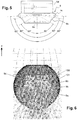
- the figure 6 represents a calculated distribution of light energy, in a plane of symmetry of the globe parallel to the z axis (corresponding to the section plane of the figure 2 ).
- Calculations have been made for a lighting device comprising a globe 101, an electronic card arranged inside the globe, serving as a support for an LED, and a diffuser 109 of the type illustrated in FIG. figure 3 , surrounding the LED and the electronic card.
- the main direction of the light emission of the LED corresponds to the z axis. The LED emits light downwards.
- the diffuser 109 makes it possible to widen the emission cone and to direct light rays towards the upper part of the globe 101, above the light source. These results show in particular that the diffuser 109 makes it possible to illuminate the critical areas 13 of the globe highlighted on the screen. figure 2 .
- the globe itself thanks to the choice of a material diffusing the light, makes it possible to homogenize the lighting of the globe (the material specifically chosen for the globe has not been taken into account in the modeling).
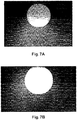
- FIGS. 7A and 7B are photographs illustrating the performance of a lighting device of the type illustrated in figure 1 , respectively without diffuser and with a diffuser of the type illustrated in figure 3 .
- An advantage of a lighting device of the type described in connection with the figure 1 lies in the fact that it provides a uniform illumination of the globe.
- Another advantage of such a lighting device is related to the fact that the diffuser constitutes a resonance cage for the light rays. This maximizes the light energy emitted by the lighting device.
- Another advantage of such a lighting device is related to the fact that the diffuser makes it possible to position and hold in place the constituent elements of the control circuit in the globe.
- Another advantage of such a lighting device lies in the ability to integrate a large part of the electronic elements required for the operation of the device inside the globe itself, without these elements are perceived from the outside.
- Another advantage of a lighting device of the type described in connection with the figure 1 resides in the fact that the use of a diffuser inside the globe makes it possible to use only one source of light. This makes it easier to control the light intensity and the color of the globe lighting.
- the inventor further proposes to produce a lighting system comprising a set of lighting devices (or globes or luminous spheres) such as that described in connection with the figure 1 .
- Such a lighting system comprises for example at least 1000 globes or light spheres, for example arranged in a matrix of 32 lines and 32 columns.
- the luminous spheres can be connected by wires to a ceiling lamp.
- Such a lighting system makes it possible to control the movement (for example vertical), the luminous intensity and / or the color of each luminous sphere (or "pixel") independently of the other luminous spheres.
Landscapes
- Engineering & Computer Science (AREA)
- General Engineering & Computer Science (AREA)
- Microelectronics & Electronic Packaging (AREA)
- Non-Portable Lighting Devices Or Systems Thereof (AREA)
Claims (15)
- Beleuchtungsvorrichtung, aufweisend:eine Lichtquelle (3), die ausgebildet ist, Licht gemäß einem Lichtkegel abzustrahlen;einen elektronischen Schaltkreis (5) zur Steuerung der Lichtquelle (3);eine Wand, deren Form eine Umhüllung (1) definiert, welche die Lichtquelle (3) und den elektronischen Schaltkreis (5) umgibt, wobei die Wand mindestens eine erste Zone, die der Schnittlinie zum Lichtkegel entspricht, und eine zweite Zone aufweist, die zur ersten Zone komplementär ist;einen Diffusor (9), der ein lichtstreuendes Material aufweist und im Inneren der Umhüllung (1) angeordnet ist, und zwar zwischen der Lichtquelle (3) und der ersten Zone, wobei der Diffusor (9) ausgebildet ist, einen Teil des Lichtes durch Rückstreuung hin zu der zweiten Zone zu lenken;wobei der elektronische Schaltkreis (5) in einem ersten Teil angeordnet ist, der als oberer Teil der Umhüllung (1) bezeichnet wird, wobei der Lichtkegel von der Lichtquelle (3) hin zu einem zweiten Teil ausgesendet wird, der als unterer Teil der Umhüllung (1) bezeichnet wird;dadurch gekennzeichnet, dassder Diffusor (9) einen ersten Teil (9a), der senkrecht zur Rotationsachse des Lichtkegels ausgerichtet ist und eine erste Zerstreuungslinse bildet, und einen zweiten Teil (9b) aufweist, der eine zweite Zerstreuungslinse bildet, wobei der zweite Teil (9b) die Form eines sich erweiternden Kegelstumpfes aufweist, dessen Rotationsachse zur Rotationsachse des Lichtkegels parallel ist und bei dem das Ende von größerem Durchmesser näher an der Lichtquelle (3) ist und das Ende von kleinerem Durchmesser benachbart zum ersten Teil (9a) ist und den ersten Teil (9a) umgibt.
- Beleuchtungsvorrichtung nach Anspruch 1, wobei der Diffusor (9) aus einem Material besteht, das gegenüber dem von der Lichtquelle (3) abgestrahlten Licht durchsichtig oder durchscheinend ist.
- Beleuchtungsvorrichtung nach einem der vorhergehenden Ansprüche, wobei der Diffusor (9) aus einem Material ausgebildet ist, das einen verminderten Streuungskoeffizienten aufweist, der zwischen 10 cm-1 und 100 cm-1, und vorzugsweise zwischen 40 cm-1 und 90 cm-1 beträgt
- Beleuchtungsvorrichtung nach einem der vorhergehenden Ansprüche, wobei der Krümmungsradius der zweiten Zerstreuungslinse (9b) geringer als der Krümmungsradius der ersten Zerstreuungslinse (9a) ist.
- Beleuchtungsvorrichtung nach einem der vorhergehenden Ansprüche, wobei der Diffusor (9) weiter einen dritten Teil (9c) aufweist, der eine dritte Zerstreuungslinse bildet, wobei der dritte Teil (9c) die Form eines sich erweiternden Kegelstumpfes aufweist, dessen Rotationsachse zur Rotationsachse des Lichtkegels parallel ist und bei dem das Ende von größerem Durchmesser benachbart zum zweiten Teil (9b) ist.
- Beleuchtungsvorrichtung nach Anspruch 5, wobei der Diffusor (9) weiter einen vierten Teil (9d) aufweist, der die Steuerschaltung (5) umgibt und das mechanische Haltern der Steuerschaltung in der Kugel (1) gewährleistet.
- Beleuchtungsvorrichtung nach einem der vorhergehenden Ansprüche, wobei der Diffusor (9) so angeordnet ist, dass das von der Lichtquelle (3) abgestrahlte Licht zu dem ersten (9a) und dem zweiten (9b) Teil des Diffusors gelenkt wird.
- Beleuchtungsvorrichtung nach einem der vorhergehenden Ansprüche, wobei die Steuerschaltung (5) einstückig mit der Lichtquelle (3) ist.
- Beleuchtungsvorrichtung nach einem der vorhergehenden Ansprüche, wobei die Steuerschaltung (5) mindestens eine Batterie (8) und einen Stromkreis zur Versorgung der mindestens einen Batterie mittels induktiver Kopplung aufweist.
- Beleuchtungsvorrichtung nach einem der vorhergehenden Ansprüche, wobei die Lichtquelle (3) auf einer Höhe unterhalb einer Mittelebene der Kugel (1) angeordnet ist.
- Beleuchtungsvorrichtung nach einem der vorhergehenden Ansprüche, wobei die Wand, welche die Umhüllung (1) bildet, aus einem transparenten oder durchscheinenden Material ausgebildet ist.
- Beleuchtungsvorrichtung nach einem der vorhergehenden Ansprüche, wobei die Wand, welche die Umhüllung (1) bildet, aus Polyethylen niedriger Dichte oder aus Glas besteht.
- Beleuchtungsvorrichtung nach einem der vorhergehenden Ansprüche, wobei die Wand, welche die Umhüllung (1) bildet, eine Dicke zwischen 100 µm und 1 cm aufweist.
- Beleuchtungsvorrichtung nach einem der vorhergehenden Ansprüche, wobei der Diffusor (9) aus Polyvinylchlorid besteht.
- System zur Beleuchtung, aufweisend eine Gruppierung von Beleuchtungsvorrichtungen nach einem der vorhergehenden Ansprüche.
Applications Claiming Priority (2)
| Application Number | Priority Date | Filing Date | Title |
|---|---|---|---|
| FR1363593A FR3016023A1 (fr) | 2013-12-26 | 2013-12-26 | Dispositif d'eclairage de forme spherique |
| PCT/EP2014/078964 WO2015097136A1 (fr) | 2013-12-26 | 2014-12-22 | Dispositif d'eclairage de forme spherique |
Publications (2)
| Publication Number | Publication Date |
|---|---|
| EP3087308A1 EP3087308A1 (de) | 2016-11-02 |
| EP3087308B1 true EP3087308B1 (de) | 2018-03-21 |
Family
ID=50483067
Family Applications (1)
| Application Number | Title | Priority Date | Filing Date |
|---|---|---|---|
| EP14815768.8A Not-in-force EP3087308B1 (de) | 2013-12-26 | 2014-12-22 | Sphärische beleuchtungsvorrichtung |
Country Status (4)
| Country | Link |
|---|---|
| US (1) | US9791126B2 (de) |
| EP (1) | EP3087308B1 (de) |
| FR (1) | FR3016023A1 (de) |
| WO (1) | WO2015097136A1 (de) |
Families Citing this family (6)
| Publication number | Priority date | Publication date | Assignee | Title |
|---|---|---|---|---|
| USD791396S1 (en) | 2016-01-18 | 2017-07-04 | Kuzco Lighting | Lighting enclosure |
| MX2020004037A (es) * | 2017-10-18 | 2020-11-09 | Lsi Industries Inc | Luminaria montada en una superficie. |
| JP2020053184A (ja) * | 2018-09-25 | 2020-04-02 | 東芝ライテック株式会社 | 照明装置 |
| USD925097S1 (en) | 2018-10-18 | 2021-07-13 | Lsi Industries, Inc. | Surface mount luminaire |
| JP7132503B2 (ja) * | 2018-11-20 | 2022-09-07 | 日本電信電話株式会社 | 照明装置 |
| JP7325023B2 (ja) * | 2021-06-30 | 2023-08-14 | パナソニックIpマネジメント株式会社 | Led照明装置及びled照明器具 |
Family Cites Families (12)
| Publication number | Priority date | Publication date | Assignee | Title |
|---|---|---|---|---|
| DE19918370B4 (de) * | 1999-04-22 | 2006-06-08 | Osram Opto Semiconductors Gmbh | LED-Weißlichtquelle mit Linse |
| JP2009295299A (ja) * | 2008-06-02 | 2009-12-17 | Tamura Seisakusho Co Ltd | 照明体 |
| US8506103B2 (en) * | 2008-11-26 | 2013-08-13 | Keiji Iimura | Semiconductor lamp and light bulb type LED lamp |
| US8449150B2 (en) * | 2009-02-03 | 2013-05-28 | Osram Sylvania Inc. | Tir lens for light emitting diodes |
| US9103507B2 (en) * | 2009-10-02 | 2015-08-11 | GE Lighting Solutions, LLC | LED lamp with uniform omnidirectional light intensity output |
| WO2011050273A2 (en) | 2009-10-22 | 2011-04-28 | Waqidi Falicoff | Remote-phosphor light engines and lamps |
| DE102010014520A1 (de) * | 2010-04-09 | 2011-10-13 | Christian Bartenbach | Leuchte |
| US8395310B2 (en) * | 2011-03-16 | 2013-03-12 | Bridgelux, Inc. | Method and apparatus for providing omnidirectional illumination using LED lighting |
| US9004724B2 (en) * | 2011-03-21 | 2015-04-14 | GE Lighting Solutions, LLC | Reflector (optics) used in LED deco lamp |
| US8604684B2 (en) * | 2011-05-16 | 2013-12-10 | Cree, Inc. | UV stable optical element and LED lamp using same |
| WO2013009728A2 (en) * | 2011-07-12 | 2013-01-17 | Reliabulb, Llc | Led light bulb replicating the light pattern of an incandescent light bulb |
| JP2013105711A (ja) * | 2011-11-16 | 2013-05-30 | Toshiba Lighting & Technology Corp | 照明器具 |
-
2013
- 2013-12-26 FR FR1363593A patent/FR3016023A1/fr active Pending
-
2014
- 2014-12-22 WO PCT/EP2014/078964 patent/WO2015097136A1/fr not_active Ceased
- 2014-12-22 US US15/107,780 patent/US9791126B2/en not_active Expired - Fee Related
- 2014-12-22 EP EP14815768.8A patent/EP3087308B1/de not_active Not-in-force
Also Published As
| Publication number | Publication date |
|---|---|
| US9791126B2 (en) | 2017-10-17 |
| WO2015097136A1 (fr) | 2015-07-02 |
| FR3016023A1 (fr) | 2015-07-03 |
| US20160327240A1 (en) | 2016-11-10 |
| EP3087308A1 (de) | 2016-11-02 |
Similar Documents
| Publication | Publication Date | Title |
|---|---|---|
| EP3087308B1 (de) | Sphärische beleuchtungsvorrichtung | |
| EP1288562B1 (de) | Beleuchtungs- oder Signalvorrichtung für Fahrzeug | |
| EP1731423A1 (de) | Antikollisionsleuchte | |
| CA2930392C (fr) | Dispositif d'eclairage pour aeronef permettant l'integration en son centre de fonctions additionnelles | |
| FR3039880B1 (fr) | Dispositif d’eclairage et/ou de signalisation pour vehicule automobile | |
| JP4988822B2 (ja) | 照明システム | |
| JP2016110869A (ja) | 発光装置および光束制御部材 | |
| EP2886942A1 (de) | Beleuchtungsvorrichtung | |
| CN104421839A (zh) | 一种led透镜、摄像装置及照明装置 | |
| EP2418539B1 (de) | Beleuchtungs- und Auflagevorrichtung zum Fotografieren eines Objekts | |
| EP2060849B1 (de) | Beleuchtungsvorrichtung mit punktartigen Lichtquellen | |
| US20160102844A1 (en) | Arrangement for light output comprising an led light source and a reflector | |
| EP2926049A1 (de) | Fahrzeugsignalisierungsvorrichtung mit dreidimensionaler wirkung | |
| CN104676318A (zh) | 用于借助波长转换产生光的照明装置 | |
| KR101604667B1 (ko) | 직하 백라이트유닛 확산 렌즈 | |
| EP3329181B1 (de) | Optisches system zur nicht-abbildenden kollimation mit maximaler lichtintensität | |
| FR3068110B1 (fr) | Module lumineux a eclairage variable | |
| WO2004079259A1 (fr) | Dispositif d'eclairage | |
| FR3042587B1 (fr) | Collimateur optique a encombrement reduit pour generer une petite tache d'eclairage | |
| US7372641B2 (en) | Contrast reinforcement for displays | |
| FR3035228A1 (fr) | Systeme optique | |
| FR3018363A1 (fr) | Guide de lumiere pour source de lumiere ponctuelle et dispositif d'eclairage associe | |
| FR2961290A1 (fr) | Dispositif d'eclairage |
Legal Events
| Date | Code | Title | Description |
|---|---|---|---|
| PUAI | Public reference made under article 153(3) epc to a published international application that has entered the european phase |
Free format text: ORIGINAL CODE: 0009012 |
|
| 17P | Request for examination filed |
Effective date: 20160627 |
|
| AK | Designated contracting states |
Kind code of ref document: A1 Designated state(s): AL AT BE BG CH CY CZ DE DK EE ES FI FR GB GR HR HU IE IS IT LI LT LU LV MC MK MT NL NO PL PT RO RS SE SI SK SM TR |
|
| AX | Request for extension of the european patent |
Extension state: BA ME |
|
| DAX | Request for extension of the european patent (deleted) | ||
| REG | Reference to a national code |
Ref country code: DE Ref legal event code: R079 Ref document number: 602014022747 Country of ref document: DE Free format text: PREVIOUS MAIN CLASS: F21S0008000000 Ipc: F21V0005040000 |
|
| RIC1 | Information provided on ipc code assigned before grant |
Ipc: F21V 7/22 20060101ALI20170828BHEP Ipc: F21V 5/04 20060101AFI20170828BHEP Ipc: F21V 3/04 20060101ALI20170828BHEP Ipc: F21Y 115/10 20160101ALI20170828BHEP |
|
| GRAP | Despatch of communication of intention to grant a patent |
Free format text: ORIGINAL CODE: EPIDOSNIGR1 |
|
| STAA | Information on the status of an ep patent application or granted ep patent |
Free format text: STATUS: GRANT OF PATENT IS INTENDED |
|
| INTG | Intention to grant announced |
Effective date: 20171010 |
|
| GRAS | Grant fee paid |
Free format text: ORIGINAL CODE: EPIDOSNIGR3 |
|
| GRAA | (expected) grant |
Free format text: ORIGINAL CODE: 0009210 |
|
| STAA | Information on the status of an ep patent application or granted ep patent |
Free format text: STATUS: THE PATENT HAS BEEN GRANTED |
|
| AK | Designated contracting states |
Kind code of ref document: B1 Designated state(s): AL AT BE BG CH CY CZ DE DK EE ES FI FR GB GR HR HU IE IS IT LI LT LU LV MC MK MT NL NO PL PT RO RS SE SI SK SM TR |
|
| REG | Reference to a national code |
Ref country code: GB Ref legal event code: FG4D Free format text: NOT ENGLISH |
|
| REG | Reference to a national code |
Ref country code: CH Ref legal event code: EP |
|
| REG | Reference to a national code |
Ref country code: AT Ref legal event code: REF Ref document number: 981491 Country of ref document: AT Kind code of ref document: T Effective date: 20180415 |
|
| REG | Reference to a national code |
Ref country code: IE Ref legal event code: FG4D Free format text: LANGUAGE OF EP DOCUMENT: FRENCH |
|
| REG | Reference to a national code |
Ref country code: DE Ref legal event code: R096 Ref document number: 602014022747 Country of ref document: DE |
|
| REG | Reference to a national code |
Ref country code: NL Ref legal event code: MP Effective date: 20180321 |
|
| PG25 | Lapsed in a contracting state [announced via postgrant information from national office to epo] |
Ref country code: CY Free format text: LAPSE BECAUSE OF FAILURE TO SUBMIT A TRANSLATION OF THE DESCRIPTION OR TO PAY THE FEE WITHIN THE PRESCRIBED TIME-LIMIT Effective date: 20180321 Ref country code: NO Free format text: LAPSE BECAUSE OF FAILURE TO SUBMIT A TRANSLATION OF THE DESCRIPTION OR TO PAY THE FEE WITHIN THE PRESCRIBED TIME-LIMIT Effective date: 20180621 Ref country code: FI Free format text: LAPSE BECAUSE OF FAILURE TO SUBMIT A TRANSLATION OF THE DESCRIPTION OR TO PAY THE FEE WITHIN THE PRESCRIBED TIME-LIMIT Effective date: 20180321 Ref country code: HR Free format text: LAPSE BECAUSE OF FAILURE TO SUBMIT A TRANSLATION OF THE DESCRIPTION OR TO PAY THE FEE WITHIN THE PRESCRIBED TIME-LIMIT Effective date: 20180321 Ref country code: LT Free format text: LAPSE BECAUSE OF FAILURE TO SUBMIT A TRANSLATION OF THE DESCRIPTION OR TO PAY THE FEE WITHIN THE PRESCRIBED TIME-LIMIT Effective date: 20180321 |
|
| REG | Reference to a national code |
Ref country code: LT Ref legal event code: MG4D |
|
| REG | Reference to a national code |
Ref country code: AT Ref legal event code: MK05 Ref document number: 981491 Country of ref document: AT Kind code of ref document: T Effective date: 20180321 |
|
| PG25 | Lapsed in a contracting state [announced via postgrant information from national office to epo] |
Ref country code: GR Free format text: LAPSE BECAUSE OF FAILURE TO SUBMIT A TRANSLATION OF THE DESCRIPTION OR TO PAY THE FEE WITHIN THE PRESCRIBED TIME-LIMIT Effective date: 20180622 Ref country code: SE Free format text: LAPSE BECAUSE OF FAILURE TO SUBMIT A TRANSLATION OF THE DESCRIPTION OR TO PAY THE FEE WITHIN THE PRESCRIBED TIME-LIMIT Effective date: 20180321 Ref country code: LV Free format text: LAPSE BECAUSE OF FAILURE TO SUBMIT A TRANSLATION OF THE DESCRIPTION OR TO PAY THE FEE WITHIN THE PRESCRIBED TIME-LIMIT Effective date: 20180321 Ref country code: RS Free format text: LAPSE BECAUSE OF FAILURE TO SUBMIT A TRANSLATION OF THE DESCRIPTION OR TO PAY THE FEE WITHIN THE PRESCRIBED TIME-LIMIT Effective date: 20180321 Ref country code: BG Free format text: LAPSE BECAUSE OF FAILURE TO SUBMIT A TRANSLATION OF THE DESCRIPTION OR TO PAY THE FEE WITHIN THE PRESCRIBED TIME-LIMIT Effective date: 20180621 |
|
| PG25 | Lapsed in a contracting state [announced via postgrant information from national office to epo] |
Ref country code: MT Free format text: LAPSE BECAUSE OF FAILURE TO SUBMIT A TRANSLATION OF THE DESCRIPTION OR TO PAY THE FEE WITHIN THE PRESCRIBED TIME-LIMIT Effective date: 20180321 |
|
| PG25 | Lapsed in a contracting state [announced via postgrant information from national office to epo] |
Ref country code: ES Free format text: LAPSE BECAUSE OF FAILURE TO SUBMIT A TRANSLATION OF THE DESCRIPTION OR TO PAY THE FEE WITHIN THE PRESCRIBED TIME-LIMIT Effective date: 20180321 Ref country code: EE Free format text: LAPSE BECAUSE OF FAILURE TO SUBMIT A TRANSLATION OF THE DESCRIPTION OR TO PAY THE FEE WITHIN THE PRESCRIBED TIME-LIMIT Effective date: 20180321 Ref country code: NL Free format text: LAPSE BECAUSE OF FAILURE TO SUBMIT A TRANSLATION OF THE DESCRIPTION OR TO PAY THE FEE WITHIN THE PRESCRIBED TIME-LIMIT Effective date: 20180321 Ref country code: RO Free format text: LAPSE BECAUSE OF FAILURE TO SUBMIT A TRANSLATION OF THE DESCRIPTION OR TO PAY THE FEE WITHIN THE PRESCRIBED TIME-LIMIT Effective date: 20180321 Ref country code: IT Free format text: LAPSE BECAUSE OF FAILURE TO SUBMIT A TRANSLATION OF THE DESCRIPTION OR TO PAY THE FEE WITHIN THE PRESCRIBED TIME-LIMIT Effective date: 20180321 Ref country code: PL Free format text: LAPSE BECAUSE OF FAILURE TO SUBMIT A TRANSLATION OF THE DESCRIPTION OR TO PAY THE FEE WITHIN THE PRESCRIBED TIME-LIMIT Effective date: 20180321 Ref country code: AL Free format text: LAPSE BECAUSE OF FAILURE TO SUBMIT A TRANSLATION OF THE DESCRIPTION OR TO PAY THE FEE WITHIN THE PRESCRIBED TIME-LIMIT Effective date: 20180321 |
|
| PG25 | Lapsed in a contracting state [announced via postgrant information from national office to epo] |
Ref country code: SK Free format text: LAPSE BECAUSE OF FAILURE TO SUBMIT A TRANSLATION OF THE DESCRIPTION OR TO PAY THE FEE WITHIN THE PRESCRIBED TIME-LIMIT Effective date: 20180321 Ref country code: AT Free format text: LAPSE BECAUSE OF FAILURE TO SUBMIT A TRANSLATION OF THE DESCRIPTION OR TO PAY THE FEE WITHIN THE PRESCRIBED TIME-LIMIT Effective date: 20180321 Ref country code: SM Free format text: LAPSE BECAUSE OF FAILURE TO SUBMIT A TRANSLATION OF THE DESCRIPTION OR TO PAY THE FEE WITHIN THE PRESCRIBED TIME-LIMIT Effective date: 20180321 Ref country code: CZ Free format text: LAPSE BECAUSE OF FAILURE TO SUBMIT A TRANSLATION OF THE DESCRIPTION OR TO PAY THE FEE WITHIN THE PRESCRIBED TIME-LIMIT Effective date: 20180321 |
|
| PG25 | Lapsed in a contracting state [announced via postgrant information from national office to epo] |
Ref country code: PT Free format text: LAPSE BECAUSE OF FAILURE TO SUBMIT A TRANSLATION OF THE DESCRIPTION OR TO PAY THE FEE WITHIN THE PRESCRIBED TIME-LIMIT Effective date: 20180723 |
|
| REG | Reference to a national code |
Ref country code: DE Ref legal event code: R097 Ref document number: 602014022747 Country of ref document: DE |
|
| PLBE | No opposition filed within time limit |
Free format text: ORIGINAL CODE: 0009261 |
|
| STAA | Information on the status of an ep patent application or granted ep patent |
Free format text: STATUS: NO OPPOSITION FILED WITHIN TIME LIMIT |
|
| PG25 | Lapsed in a contracting state [announced via postgrant information from national office to epo] |
Ref country code: DK Free format text: LAPSE BECAUSE OF FAILURE TO SUBMIT A TRANSLATION OF THE DESCRIPTION OR TO PAY THE FEE WITHIN THE PRESCRIBED TIME-LIMIT Effective date: 20180321 |
|
| 26N | No opposition filed |
Effective date: 20190102 |
|
| PG25 | Lapsed in a contracting state [announced via postgrant information from national office to epo] |
Ref country code: SI Free format text: LAPSE BECAUSE OF FAILURE TO SUBMIT A TRANSLATION OF THE DESCRIPTION OR TO PAY THE FEE WITHIN THE PRESCRIBED TIME-LIMIT Effective date: 20180321 |
|
| REG | Reference to a national code |
Ref country code: CH Ref legal event code: PL |
|
| GBPC | Gb: european patent ceased through non-payment of renewal fee |
Effective date: 20181222 |
|
| PG25 | Lapsed in a contracting state [announced via postgrant information from national office to epo] |
Ref country code: LU Free format text: LAPSE BECAUSE OF NON-PAYMENT OF DUE FEES Effective date: 20181222 Ref country code: MC Free format text: LAPSE BECAUSE OF FAILURE TO SUBMIT A TRANSLATION OF THE DESCRIPTION OR TO PAY THE FEE WITHIN THE PRESCRIBED TIME-LIMIT Effective date: 20180321 |
|
| REG | Reference to a national code |
Ref country code: IE Ref legal event code: MM4A |
|
| REG | Reference to a national code |
Ref country code: BE Ref legal event code: MM Effective date: 20181231 |
|
| PG25 | Lapsed in a contracting state [announced via postgrant information from national office to epo] |
Ref country code: IE Free format text: LAPSE BECAUSE OF NON-PAYMENT OF DUE FEES Effective date: 20181222 |
|
| PG25 | Lapsed in a contracting state [announced via postgrant information from national office to epo] |
Ref country code: BE Free format text: LAPSE BECAUSE OF NON-PAYMENT OF DUE FEES Effective date: 20181231 |
|
| PG25 | Lapsed in a contracting state [announced via postgrant information from national office to epo] |
Ref country code: LI Free format text: LAPSE BECAUSE OF NON-PAYMENT OF DUE FEES Effective date: 20181231 Ref country code: CH Free format text: LAPSE BECAUSE OF NON-PAYMENT OF DUE FEES Effective date: 20181231 Ref country code: GB Free format text: LAPSE BECAUSE OF NON-PAYMENT OF DUE FEES Effective date: 20181222 |
|
| PGFP | Annual fee paid to national office [announced via postgrant information from national office to epo] |
Ref country code: DE Payment date: 20191216 Year of fee payment: 6 |
|
| PGFP | Annual fee paid to national office [announced via postgrant information from national office to epo] |
Ref country code: FR Payment date: 20191231 Year of fee payment: 6 |
|
| PG25 | Lapsed in a contracting state [announced via postgrant information from national office to epo] |
Ref country code: TR Free format text: LAPSE BECAUSE OF FAILURE TO SUBMIT A TRANSLATION OF THE DESCRIPTION OR TO PAY THE FEE WITHIN THE PRESCRIBED TIME-LIMIT Effective date: 20180321 |
|
| PG25 | Lapsed in a contracting state [announced via postgrant information from national office to epo] |
Ref country code: MK Free format text: LAPSE BECAUSE OF NON-PAYMENT OF DUE FEES Effective date: 20180321 Ref country code: HU Free format text: LAPSE BECAUSE OF FAILURE TO SUBMIT A TRANSLATION OF THE DESCRIPTION OR TO PAY THE FEE WITHIN THE PRESCRIBED TIME-LIMIT; INVALID AB INITIO Effective date: 20141222 |
|
| PG25 | Lapsed in a contracting state [announced via postgrant information from national office to epo] |
Ref country code: IS Free format text: LAPSE BECAUSE OF FAILURE TO SUBMIT A TRANSLATION OF THE DESCRIPTION OR TO PAY THE FEE WITHIN THE PRESCRIBED TIME-LIMIT Effective date: 20180721 |
|
| REG | Reference to a national code |
Ref country code: DE Ref legal event code: R119 Ref document number: 602014022747 Country of ref document: DE |
|
| PG25 | Lapsed in a contracting state [announced via postgrant information from national office to epo] |
Ref country code: FR Free format text: LAPSE BECAUSE OF NON-PAYMENT OF DUE FEES Effective date: 20201231 |
|
| PG25 | Lapsed in a contracting state [announced via postgrant information from national office to epo] |
Ref country code: DE Free format text: LAPSE BECAUSE OF NON-PAYMENT OF DUE FEES Effective date: 20210701 |