EP3086442B1 - Elektrische maschine mit einem ersten aktivteil und einem zweiten aktivteil - Google Patents
Elektrische maschine mit einem ersten aktivteil und einem zweiten aktivteil Download PDFInfo
- Publication number
- EP3086442B1 EP3086442B1 EP15164650.2A EP15164650A EP3086442B1 EP 3086442 B1 EP3086442 B1 EP 3086442B1 EP 15164650 A EP15164650 A EP 15164650A EP 3086442 B1 EP3086442 B1 EP 3086442B1
- Authority
- EP
- European Patent Office
- Prior art keywords
- active part
- segment
- winding
- terminal element
- connection
- Prior art date
- Legal status (The legal status is an assumption and is not a legal conclusion. Google has not performed a legal analysis and makes no representation as to the accuracy of the status listed.)
- Active
Links
Images




Classifications
-
- H—ELECTRICITY
- H02—GENERATION; CONVERSION OR DISTRIBUTION OF ELECTRIC POWER
- H02K—DYNAMO-ELECTRIC MACHINES
- H02K3/00—Details of windings
- H02K3/04—Windings characterised by the conductor shape, form or construction, e.g. with bar conductors
- H02K3/12—Windings characterised by the conductor shape, form or construction, e.g. with bar conductors arranged in slots
-
- H—ELECTRICITY
- H02—GENERATION; CONVERSION OR DISTRIBUTION OF ELECTRIC POWER
- H02K—DYNAMO-ELECTRIC MACHINES
- H02K7/00—Arrangements for handling mechanical energy structurally associated with dynamo-electric machines, e.g. structural association with mechanical driving motors or auxiliary dynamo-electric machines
- H02K7/18—Structural association of electric generators with mechanical driving motors, e.g. with turbines
- H02K7/1807—Rotary generators
- H02K7/1823—Rotary generators structurally associated with turbines or similar engines
- H02K7/183—Rotary generators structurally associated with turbines or similar engines wherein the turbine is a wind turbine
- H02K7/1838—Generators mounted in a nacelle or similar structure of a horizontal axis wind turbine
-
- H—ELECTRICITY
- H02—GENERATION; CONVERSION OR DISTRIBUTION OF ELECTRIC POWER
- H02K—DYNAMO-ELECTRIC MACHINES
- H02K2201/00—Specific aspects not provided for in the other groups of this subclass relating to the magnetic circuits
- H02K2201/15—Sectional machines
-
- H—ELECTRICITY
- H02—GENERATION; CONVERSION OR DISTRIBUTION OF ELECTRIC POWER
- H02K—DYNAMO-ELECTRIC MACHINES
- H02K2213/00—Specific aspects, not otherwise provided for and not covered by codes H02K2201/00 - H02K2211/00
- H02K2213/12—Machines characterised by the modularity of some components
-
- Y—GENERAL TAGGING OF NEW TECHNOLOGICAL DEVELOPMENTS; GENERAL TAGGING OF CROSS-SECTIONAL TECHNOLOGIES SPANNING OVER SEVERAL SECTIONS OF THE IPC; TECHNICAL SUBJECTS COVERED BY FORMER USPC CROSS-REFERENCE ART COLLECTIONS [XRACs] AND DIGESTS
- Y02—TECHNOLOGIES OR APPLICATIONS FOR MITIGATION OR ADAPTATION AGAINST CLIMATE CHANGE
- Y02E—REDUCTION OF GREENHOUSE GAS [GHG] EMISSIONS, RELATED TO ENERGY GENERATION, TRANSMISSION OR DISTRIBUTION
- Y02E10/00—Energy generation through renewable energy sources
- Y02E10/70—Wind energy
- Y02E10/72—Wind turbines with rotation axis in wind direction
Definitions
- the present invention relates to an electrical machine with a first active part and a second active part.
- the second active part can be moved in the direction of movement relative to the first active part.
- the first active part comprises at least one first active part segment and at least one second active part segment.
- the first active part has at least one winding, which comprises a first winding section and a second winding section.
- the first active part segment has slots in which the first winding section is arranged.
- the second active part segment also has slots in which the second winding section is arranged.
- a motor for example, has a stator and a rotor as the respective active part.
- Coils can be inserted or wrapped in the stator and / or rotor of a motor or generator.
- the coils are then typically located in or on a sheet metal package or iron package.
- the coils protrude from the winding head sides of the cylindrical or hollow cylindrical laminated cores and form a winding head of the rotor or stator.
- the sheet metal packages or iron packages are segmented on account of the processability and transportability.
- Such generators of large size are used for example in wind turbines.
- Segmented iron packs or sheet metal packs are used, for example, in generators of a wind turbine.
- this segmentability offers some disadvantages for winding technology.
- the use of two-layer windings is not possible with segmented laminated cores. This then leads to special measures, such as folding coils or single-layer windings. If, for example, folding coil two-layer windings are used, complex installation and insulation of the coil are required when installing the segments. Furthermore, the exchange of defective segments is very time-consuming and costly.
- single-layer windings are used instead of folding coil two-layer windings, the coil dimensions are very large and different coil shapes are necessary.
- a stator for a dynamoelectric machine In the EP 2 020 731 A1 describes a stator for a dynamoelectric machine.
- a laminated core of the stator consists of individual sheets. Windings are arranged in the slots of the laminated core. A winding end region of the windings protrudes from an end face of the laminated core.
- the EP 2 211 443 A1 relates to a stator of a ring generator with a stator segment and a further stator segment.
- the respective stator segments comprise a base body and a coil element which is arranged on the base body.
- the stator has a stator core, which is formed by bringing together at least one layered core part into a cylindrical stator core. Furthermore, the stator has a stator winding which is arranged in the stator core. The stator winding is arranged such that a conductor wire alternately occupies an inner layer and an outer layer in slots in the stator core.
- the object of the invention is to design and design a winding of an electrical machine with a segmented active part to be particularly efficient.
- an electrical machine with a first active part and a second active part.
- the second active part can be moved in the direction of movement relative to the first active part.
- the first active part is arranged stationary to the second active part.
- the first active part comprises at least one first active part segment and at least one second active part segment.
- the active part can also comprise more than two active part segments.
- segments here is meant that the laminated core of the first active part is segmented relative to the direction of movement of the second active part.
- the first active part has at least one winding, which comprises a first winding section and a second winding section.
- the first active part segment has slots in which the first winding section is arranged.
- the second active part segment also has slots in which the second winding section is arranged.
- the winding system of the first active part thus has, for example, a single winding.
- the winding can comprise several conductors, which are assigned to a phase.
- a winding can therefore have several phases.
- this winding can be divided into winding segments, that is to say winding sections. That is, the at least one winding is composed of the first winding section and the second winding section. If the first active part comprised, for example, three active part segments, the winding would be in three winding sections be divided.
- a winding section is therefore a section of the at least one winding which is arranged in the slots of the respective active part segment.
- the first active part segment and the second active part segment can thus comprise a laminated core segment or an iron core segment which has grooves.
- a first winding section or a second winding section is inserted into the slots in the respective laminated core segment or iron core segment.
- the first winding section also has a first connection element which is arranged on a first end face of the first active part segment.
- the second winding section has a second connection element which is arranged on a second end face of the second active part segment.
- a connection element here means, for example, an end region of the first and second winding sections.
- the connection element is part of the respective winding section.
- the first and the second winding section have an end region which can protrude on the respective end face of the respective active part segment.
- the connection element of the winding section can protrude from a groove of the active part segment like a winding overhang of the winding section on a winding head side.
- first end face of the first active part segment and the second end face of the second active part segment are arranged adjacent to one another and parallel to one another in the direction of movement of the second active part.
- first end face of the first active part segment and the second end face of the second active part segment are arranged substantially perpendicular to the direction of movement of the second active part segment and parallel to one another.
- the end face of the active part segment means, for example, the area which extends at one end of the active part segment or laminated core segment perpendicular to the main direction of extension of the active part segment or laminated core segment.
- the first connection element and the second connection element arranged side by side. In other words, the first active part segment and the second active part segment are assigned to one another. Furthermore, the first and the second connection element are connected.
- the first active part of the electrical machine can also comprise a plurality of active part segments, the adjacent and first active part segments in each case being electrically connected to one another.
- the individual winding sections are electrically connected to one another to form the winding of the first active part.
- the winding can also have corresponding contact elements on which the winding can be connected to a voltage source or on which an electrical voltage generated in the winding can be tapped.
- the design or division of the winding has the advantage that the segments - first active part segment and second active part segment - can be completely completed by the manufacturer. Furthermore, interchangeability is much easier for the customer.
- a segment transition region can be formed between the first active part segment and the second active part segment.
- the first connection element of the first active part segment and the second connection element of the second active part segment are assigned to one another.
- the first connection element and the second connection element are arranged next to one another in the direction of movement of the second active part perpendicular to the direction of movement of the second active part.
- the first connection element and the second connection element can be in the direction of movement of the second active part perpendicular to the direction of movement of the second active part in overlap with one another, that is to say one above the other.
- first connection element and the second connection element are arranged next to one another in the direction of movement of the second active part.
- first connection element and the second connection element can be arranged parallel to one another in the direction of movement of the second active part.
- the at least one winding comprises a plurality of turns which has a plurality of partial conductors.
- the at least one winding can have four turns, for example.
- each turn can comprise three partial conductors.
- the turns with their partial conductors of the first connection element and the second connection element are exposed. If the active part segments are connected to one another, the windings of the first connection element are correspondingly assigned to the windings of the second connection element.
- windings of the first connection element and the windings of the second connection element in the direction of movement of the second active part are alternately arranged next to one another or the windings of the first connection element and the windings of the second connection element in the movement direction of the second active part are arranged next to one another perpendicular to the direction of movement of the second active part.
- the first active part segment and the second active part segment are advantageously arranged on a carrier element.
- the carrier element can serve, for example, as a support for the first active part segment and the second active part segment.
- the respective active part segments - first active part segment and second active part segment - can be on the carrier element, be fixed, for example by means of a screw connection. This results in the advantage that the arrangement of the active part segments of the electrical machine can be particularly stable and at the same time particularly precise to one another.
- connection connection furthermore, for example, electrically connects the first winding section and the second winding section to one another.
- the connection connection can preferably be designed as a crimp connection or as a solder connection. This has the advantage that the connection is particularly stable. Other types of connection between the first connection element and the second connection element may also be conceivable.
- connection between the first connection element and the second connection element can be designed as a releasable connection and / or as a non-releasable connection.
- a clamp connection can be provided, for example, between the first connection element and the second connection element.
- This clamp connection can be implemented according to the luster clamp principle.
- the detachable connection has the advantage that the respective segments are particularly easy to replace.
- the first connection element and / or the second connection element can advantageously be electrically insulated by means of an insulating element.
- the insulating element is preferably designed as an impregnating resin and / or as a shrink tube. This has the advantage that the respective connection elements can be isolated in a particularly simple and cost-effective manner.
- the second active part is advantageously designed as a stator or rotor. Due to the segmented active part the corresponding electrical machine can be made more compact than a machine with a conventional stator or rotor with a conventional winding design.
- the invention also includes a wind power plant with an electrical machine.
- the electrical machine is in particular an embodiment of the electrical machine according to the invention.
- FIG. 1 A general structure of an electrical machine 10 is shown.
- the electrical machine 10 can be, for example, a motor or a generator.
- the electrical machine 10 can be used, for example, as a generator of a wind power machine.
- an axis of rotation R also represents an axis of symmetry of the representation.
- the electrical machine 10 comprises a first active part 12 in the form of a stator, in which windings of electrical coils are arranged, wherein in FIG FIG. 1 only one of the windings 14 is shown.
- the windings 14 are alternately supplied with current by a three-phase current source C, as a result of which a magnetic rotating field arises in an air gap L of the electrical machine 10 in the interior of the stator.
- the three-phase source C can be, for example, an inverter or a fixed-frequency electrical supply network.
- first active part 12 there is a second active part 16 in the form of a rotor, which is connected in a rotationally fixed manner to a shaft 18.
- the shaft 18 is rotatable about the axis of rotation R and is mounted in the first active part 12.
- the invention is based on an electrical machine 10 with an internal one Rotor described.
- the electrical machine 10 can also be an external rotor.
- the stator is arranged inside the rotor. It can also be a linear motor.
- FIG 2 an iron packet with iron packet segments 20 is shown.
- the iron package is segmented on account of the processability and transportability. Since the electrical machine 10 is designed to be rotary, the iron packet segments 20 are bent in a circle around the axis of rotation R. If the electrical machine 10 were a linear machine, the iron package segments 20 would be straight.
- the iron packet segments 20 are like FIG 2 can be seen, preferably constructed the same.
- the first active part segment 22 is shown.
- the first active part segment 22 is part of the first active part 12, which is composed of at least one first active part segment 22 and at least one second active part segment (in FIG 3 not shown).
- the first active part 12 can in particular be a stator.
- the first active part segment 22 comprises, as in FIG FIG 2 shown, an iron package segment 20 with first slots 30.
- a first winding section 26 is arranged or inserted.
- a first connection element 34 projects out of one of the first grooves 30 on a first end face 50.
- the first active part segment 22 can also, like FIG 3 it can be seen, at a further end opposite the first end 46, a further connection element which can be formed analogously to the first connection element 34.
- the first winding section 26 comprises a plurality of turns which have a plurality of partial conductors.
- the first winding section 26 has four first turns 36. Each turn comprises three first partial conductors 38.
- This division of the first winding section 26 can be seen precisely on the first connection element 34. This division, ie the number of turns and the number of partial conductors per turn, applies analogously to the second winding section (in FIG 3 not shown).
- the first connection element 34 is stripped, ie the first turns 36 with their first partial conductors 38 individually protrude from the first winding end side 50.
- a winding part of a single winding of the winding system is arranged in each slot of the first slots 30 of the first active part segment 22. Another winding part of the winding lies in another slot 30 of the active part segment 22. In each slot 30 of the active part segment 22 there is only one winding part of one of several windings of the winding system.
- Such a winding system is also referred to as a single-layer winding.
- the first winding section 26 is composed of three conductors arranged parallel to one another in individual slots 30.
- the first connection element 34 also has three conductors.
- the three conductors are successively wound with three grooves 30 offset.
- Each of the three leaders is assigned to a phase.
- a conductor leg of a conductor and a further conductor leg of a further conductor are arranged in each of the first grooves 30 of the first active part segment 22.
- the other conductor leg of the one conductor and the other conductor leg of the further conductor are arranged in two other grooves of the first grooves 30 of the first active part segment 22.
- the embodiment described for the first active part segment 22 can also be applied to the second active part segment 24, which is preferably constructed identically to the first active part segment 22.
- the second active part segment 24 comprises, for example, in FIG FIG 4 an iron package segment 20 with second slots 32.
- a second winding section 28 is arranged or inserted into the second slots 32.
- a second connection element 40 protrudes from one of the second grooves 3.
- the second winding section 28 comprises a plurality of second turns 42 which have a plurality of second partial conductors 44.
- FIG 4 and 5 describes a first embodiment of an arrangement of the first connection element 34 and the second connection element 40 when the first active part segment 22 is connected to the second active part segment 24.
- FIG 6 and 7 the second embodiment of the arrangement of an arrangement of the first connection element 34 and the second connection element 40 when the first active part segment 22 is connected to the second active part segment 24 is described.
- a section of the first active part 12 with the first active part segment 22 and the second active part segment 24 is shown.
- a respective winding section 26, 28 arranged in the respective slots 30, 32.
- the first winding section 26 has the first connection element 34, which is divided into three conductors.
- the second winding section 28 also has a second connection element 40, which is also divided into three conductors.
- the second connection element 40 and thus each conductor, comprises second turns 42. Each turn furthermore has second partial conductors 44.
- the second connection element 40 has four second turns 42, each with three second partial conductors 44.
- the first end face 48 at the first end 46 of the first active part segment 22 and the second end face 52 at the second end 52 of the second active part segment 24 are arranged adjacent to one another.
- the first connection element 34 is connected to the second connection element 40 in a segment transition area.
- the first connection element 34 and the second connection element 40 perpendicular to the direction of movement of the second active part (in 4 to 7 not shown) in overlap with each other, that is, one above the other.
- the second connection element 40 is arranged above the first connection element 34.
- the respective conductors of the respective connection elements 34, 40 are thus also arranged one above the other. As in FIG 4 and 5 a total of two conductors and thus six turns are shown one above the other.
- connection elements 34, 40 instead of arranging the connection elements 34, 40 one above the other, according to FIGS FIG 6 and 7 the first connection element 34 and the second connection element 40 can be arranged parallel to one another in the direction of movement of the second active part.
- the respective conductors of the respective connection elements 34, 40 are alternately arranged next to one another.
- the winding system of the electrical machine 10 provides a multi-layer winding, for example in the form of a three-layer winding or a four-layer winding, a combination of the first and the second embodiment can also be provided for the arrangement of the connection elements 34, 40.
- connection 58 between the first turns 36 and the second turns 42 is illustrated by arrows.
- One turn of the first turns 36 is connected to one turn of the second turns 42.
- the connection connection 58 is shown in the form of a border.
- One turn of the first turns 36 is connected to one turn of the second turns 42.
- connection connection 58 can be provided as a detachable or non-detachable connection connection for both embodiments.
- a detachable connection 58 for example, a clamp can be made according to the principle of the luster terminal.
- a crimp connection or a solder connection can be provided for permanent connections.
- coil rods are used only in the segment transition area instead of complete coils. These can then be incorporated directly into the manufacturing process and the segment can be completely impregnated.
- segment connections are required (electrical connections). If this type of connection is also selected so that it can be opened non-destructively, there is the further advantage of the much easier segment interchangeability.
Landscapes
- Engineering & Computer Science (AREA)
- Life Sciences & Earth Sciences (AREA)
- Sustainable Energy (AREA)
- Power Engineering (AREA)
- Sustainable Development (AREA)
- Windings For Motors And Generators (AREA)
Description
- Die vorliegende Erfindung betrifft eine elektrische Maschine mit einem ersten Aktivteil und einem zweiten Aktivteil. Dabei ist das zweite Aktivteil in Bewegungsrichtung relativ zu dem ersten Aktivteil bewegbar. Das erste Aktivteil umfasst mindestens ein erstes Aktivteilsegment und mindestens ein zweites Aktivteilsegment. Ferner weist das erste Aktivteil mindestens eine Wicklung auf, welche einen ersten Wicklungsabschnitt und einen zweiten Wicklungsabschnitt umfasst. Des Weiteren weist das erste Aktivteilsegment Nuten auf, in denen der erste Wicklungsabschnitt angeordnet ist. Auch das zweite Aktivteilsegment weist Nuten auf, in denen der zweite Wicklungsabschnitt angeordnet ist.
- Elektrische Maschinen und Motoren, Generatoren und Transformatoren besitzen jeweils ein oder mehrere Aktivteile, die magnetisch aktiv sind. Ein Motor beispielsweise weist einen Stator und einen Rotor als jeweiliges Aktivteil auf.
- In dem Stator und/oder Rotor eines Motors oder Generators können Spulen eingelegt beziehungsweise eingewickelt sein. Typischerweise befinden sich die Spulen dann in oder an einem Blechpaket oder Eisenpaket. In der Regel ragen aus den Wickelkopfseiten der zylindrischen oder hohlzylindrischen Blechpakete die Spulen heraus und bilden einen Wickelkopf des Rotors beziehungsweise Stators.
- Bei elektrischen Motoren oder Generatoren mit hoher Baugröße werden aufgrund der Verarbeitbarkeit und Transportierbarkeit die Blechpakete oder Eisenpakete segmentiert. Derartige Generatoren mit hoher Baugröße werden beispielsweise in Windkraftanlagen verwendet. Segmentierte Eisenpakete oder Blechpakete werden beispielsweise bei Generatoren einer Windkraftanlage verwendet. Diese Segmentierbarkeit bietet allerdings für die Wicklungstechnik einige Nachteile. Bei segmentierten Blechpaketen ist die Verwendung von Zweischichtwicklungen nicht möglich. Dies führt dann zu Sondermaßnahmen, wie beispielsweise Klappspulen oder Einschichtwicklungen. Werden zum Beispiel Klappspulen-Zweischichtwicklungen verwendet, so bedarf es beim Verbau der Segmente eines aufwendigen Spuleneinbaus und Spulenisolierung. Des Weiteren ist der Tausch von defekten Segmenten sehr zeit- und kostenaufwendig. Werden anstelle Klappspulen-Zweischichtwicklungen Einschichtwicklungen verwendet, so sind die Spulendimensionen sehr groß und es sind unterschiedliche Spulenformen notwendig.
- In der
EP 2 020 731 A1 ist ein Stator für eine dynamoelektrische Maschine beschrieben. Ein Blechpaket des Stators besteht aus Einzelblechen. In Nuten des Blechpakets sind Wicklungen angeordnet. Ein Wicklungsendbereich der Wicklungen ragt an einer Stirnseite des Blechpakets heraus. - Die
EP 2 211 443 A1 betrifft einen Stator eines Ringgenerators mit einem Statorsegment und einem weiteren Statorsegment. Die jeweiligen Statorsegmente umfassen einen Grundkörper und ein Spulenelement, welches an dem Grundkörper angeordnet ist. Zwischen den jeweiligen Statorsegmenten befindet sich ein Verbindungsbereich, in welchem die Spulenelemente des jeweiligen Statorsegments mittels eines Verbindungsspulenelements verbunden sind. - Aus der
EP 1 246 341 A2 geht ein Stator für eine dynamoelektrische Maschine hervor. Der Stator weist einen Statorkern auf, welcher durch Zusammenführen zumindest eines geschichteten Kernteils zu einem zylindrischen Statorkern geformt ist. Ferner weist der Stator eine Statorwicklung auf, welche in dem Statorkern angeordnet ist. Die Statorwicklung ist so angeordnet, dass ein Leiterdraht abwechselnd eine innere Lage und eine äußere Lage in Schlitzen des Statorkerns belegt. - Die Aufgabe der Erfindung besteht darin, eine Wicklung einer elektrischen Maschine mit einem segmentierten Aktivteil besonders effizient zu gestalten und auszulegen.
- Diese Aufgabe wird erfindungsgemäß durch die Gegenstände der unabhängigen Patentansprüche gelöst. Vorteilhafte Weiterbildungen der Erfindung ergeben sich durch die Merkmale der abhängigen Patentansprüche.
- Erfindungsgemäß wird diese Aufgabe gelöst durch eine elektrische Maschine mit einem ersten Aktivteil und einem zweiten Aktivteil. Dabei ist das zweite Aktivteil in Bewegungsrichtung relativ zu dem ersten Aktivteil bewegbar. Mit anderen Worten ist das erste Aktivteil stationär zum zweiten Aktivteil angeordnet. Des Weiteren umfasst das erste Aktivteil mindestens ein erstes Aktivteilsegment und mindestens ein zweites Aktivteilsegment. Das Aktivteil kann auch mehr als zwei Aktivteilsegmente umfassen. Mit Segmente ist hier gemeint, dass das Blechpaket des ersten Aktivteils relativ zur der Bewegungsrichtung des zweiten Aktivteils segmentiert ist. Ferner weist das erste Aktivteil mindestens eine Wicklung auf, welche einen ersten Wicklungsabschnitt und einen zweiten Wicklungsabschnitt umfasst. Des Weiteren weist das erste Aktivteilsegment Nuten auf, in denen der erste Wicklungsabschnitt angeordnet ist. Auch das zweite Aktivteilsegment weist Nuten auf, in denen der zweite Wicklungsabschnitt angeordnet ist.
- Das Wicklungssystem des ersten Aktivteils weist somit beispielsweise eine einzige Wicklung auf. Die Wicklung kann mehrere Leiter umfassen, welche einer Phase zugeordnet sind. Eine Wicklung kann also mehrere Phasen aufweisen. Diese Wicklung kann je nach Anzahl der Aktivteilsegmente in Wicklungssegmente, also Wicklungsabschnitte, aufgeteilt sein. Das heißt die mindestens eine Wicklung setzt sich aus dem ersten Wicklungsabschnitt und dem zweiten Wicklungsabschnitt zusammen. Würde das erste Aktivteil beispielsweise drei Aktivteilsegmente umfassen, so würde die Wicklung in drei Wicklungsabschnitte aufgeteilt sein. Ein Wicklungsabschnitt ist also ein Abschnitt der mindestens einen Wicklung, welcher in den Nuten des jeweiligen Aktivteilsegments angeordnet ist.
- Somit kann das ersten Aktivteilsegment und das zweites Aktivteilsegment ein Blechpaketsegment oder ein Eisenpaketsegment, welches Nuten aufweist, umfassen. In die Nuten des jeweiligen Blechpaketsegments oder Eisenpaketsegments ist ein erster Wicklungsabschnitt oder ein zweiter Wicklungsabschnitt eingelegt. Der erste Wicklungsabschnitt weist ferner ein erstes Anschlusselement auf, welches an einer ersten Stirnseite des ersten Aktivteilsegments angeordnet ist. Der zweite Wicklungsabschnitt weist ein zweites Anschlusselement auf, welches an einer zweiten Stirnseite des zweiten Aktivteilsegments angeordnet ist. Mit Anschlusselement ist hier beispielsweise ein Endbereich des ersten und zweiten Wicklungsabschnitts gemeint. Das Anschlusselement ist dabei Teil des jeweiligen Wicklungsabschnitts. Mit anderen Worten weisen der erste und der zweite Wicklungsabschnitt einen Endbereich auf, welcher an der jeweiligen Wickelkopfseite des jeweiligen Aktivteilsegments, herausragen kann. Somit kann das Anschlusselement des Wicklungsabschnitts wie ein Wicklungsüberhang des Wicklungsabschnitts an einer Wickelkopfseite aus einer Nut des Aktivteilsegments herausragen.
- Ferner sind die erste Stirnseite des ersten Aktivteilsegments und die zweite Stirnseite des zweiten Aktivteilsegments in Bewegungsrichtung des zweiten Aktivteils aneinander angrenzend und parallel zueinander angeordnet. Mit anderen Worten sind die erste Stirnseite des ersten Aktivteilsegments und die zweite Stirnseite des zweiten Aktivteilsegments im Wesentlichen senkrecht zur Bewegungsrichtung des zweiten Aktivteilsegments und parallel zueinander angeordnet. Mit Stirnseite des Aktivteilsegments ist beispielsweise die Fläche gemeint, welche sich an einem Ende des Aktivteilsegments beziehungsweise Blechpaketsegments senkrecht zur Haupterstreckungsrichtung des Aktivteilsegments oder Blechpaketsegments erstreckt. Des Weiteren sind das erste Anschlusselement und das zweite Anschlusselement nebeneinander angeordnet. Mit anderen Worten sind das erste Aktivteilsegment und das zweite Aktivteilsegment einander zugeordnet. Ferner sind das erste und das zweite Anschlusselement verbunden.
- Das erste Aktivteil der elektrischen Maschine kann auch mehrere Aktivteilsegmente umfassen, wobei bei benachbarten Aktivteilsegmenten jeweils das erste und das zweite Anschlusselemente miteinander elektrisch verbunden sind. Durch das elektrische Verbinden der ersten und zweiten Anschlusselemente werden die einzelnen Wicklungsabschnitte elektrisch miteinander zu der Wicklung des ersten Aktivteils verbunden. Die Wicklung kann auch entsprechende Kontaktelemente aufweisen, an denen die Wicklung mit einer Spannungsquelle verbunden werden kann oder an welchen eine in der Wicklung erzeugte elektrische Spannung abgegriffen werden kann.
- Durch die Gestaltung beziehungsweise Aufteilung der Wicklung ergibt sich der Vorteil, dass die Segmente - erstes Aktivteilsegment und zweites Aktivteilsegment - beim Hersteller komplett fertig gestellt werden können. Weiterhin ist die Austauschbarkeit beim Kunden viel leichter vorzunehmen.
- Durch die Anordnung der Aktivteilsegmente - erstes Aktivteilsegment und zweites Aktivteilsegment - sowie der jeweiligen Anschlusselemente - erstes Anschlusselement und zweites Anschlusselement - zueinander kann zwischen dem ersten Aktivteilsegment und dem zweiten Aktivteilsegment ein Segmentübergangsbereich ausgebildet sein. In diesem Segmentübergangsbereich sind das erste Anschlusselement des ersten Aktivteilsegments und das zweite Anschlusselement des zweiten Aktivteilsegments einander zugeordnet.
- Erfindungsgemäß sind das erste Anschlusselement und das zweite Anschlusselement in Bewegungsrichtung des zweiten Aktivteils senkrecht zur Bewegungsrichtung des zweiten Aktivteils nebeneinander angeordnet. Mit anderen Worten können das erste Anschlusselement und das zweite Anschlusselement in Bewegungsrichtung des zweiten Aktivteils senkrecht zur Bewegungsrichtung des zweiten Aktivteils in Überdeckung zueinander, also übereinander, angeordnet sein.
- Alternativ sind das erste Anschlusselement und das zweite Anschlusselement in Bewegungsrichtung des zweiten Aktivteils erfindungsgemäß nebeneinander angeordnet. Mit anderen Worten können das erste Anschlusselement und das zweite Anschlusselement in Bewegungsrichtung des zweiten Aktivteils parallel zueinander angeordnet sein. Durch die jeweilige Ausführungsform ergibt sich der Vorteil, dass bei einer Aneinanderreihung der Aktivteilsegmente die Windungsabschnitte auf besonders einfache Art und Weise miteinander verbunden werden können.
- Erfindungsgemäß umfasst die mindestens eine Wicklung mehrere Windungen, welche mehrere Teilleiter aufweist. Die mindestens eine Wicklung kann beispielsweise vier Windungen aufweisen. Jede Windung kann beispielsweise jeweils drei Teilleiter umfassen. Im Segmentübergangsbereich liegen die Windungen mit ihren Teilleitern des ersten Anschlusselements und des zweite Anschlusselement frei. Werden die Aktivteilsegmente miteinander verbunden, so sind die Windungen des ersten Anschlusselements den Windungen des zweiten Anschlusselements entsprechend zugeordnet. Ferner sind die Windungen des ersten Anschlusselements und die Windungen des zweiten Anschlusselements in Bewegungsrichtung des zweiten Aktivteils abwechselnd nebeneinander oder die Windungen des ersten Anschlusselements und die Windungen des zweiten Anschlusselements in Bewegungsrichtung des zweiten Aktivteils senkrecht zur Bewegungsrichtung des zweiten Aktivteils nebeneinander angeordnet.
- In vorteilhafter Weise sind das erste Aktivteilsegment und das zweite Aktivteilsegment auf einem Trägerelement angeordnet. Dabei kann das Trägerelement beispielsweise als Stütze für das erste Aktivteilsegment und das zweite Aktivteilsegment dienen. Die jeweiligen Aktivteilsegmente - erstes Aktivteilsegment und zweites Aktivteilsegment - können an dem Trägerelement, beispielsweise mittels einer Schraubverbindung, fixiert sein. Dadurch ergibt sich der Vorteil, dass die Anordnung der Aktivteilsegmente der elektrischen Maschine besonders stabil und zugleich besonders genau zueinander erfolgen kann.
- Eine weitere Ausführungsform der Erfindung sieht vor, dass das erste Anschlusselement und das zweite Anschlusselement mittels einer Anschlussverbindung verbunden sind. Durch die Anschlussverbindung sind ferner beispielsweise der erste Wicklungsabschnitt und der zweite Wicklungsabschnitt elektrisch miteinander verbunden. Vorzugsweise kann die Anschlussverbindung als Quetschverbindung oder als Lötverbindung ausgebildet sein. Dadurch ergibt sich der Vorteil, dass die Verbindung besonders stabil ist. Auch andere Verbindungsarten zwischen dem ersten Anschlusselement und dem zweiten Anschlusselement können denkbar sein.
- Die Anschlussverbindung zwischen dem ersten Anschlusselement und dem zweiten Anschlusselement kann als lösbare Verbindung und/oder als unlösbare Verbindung ausgestaltet sein. Bei einer lösbaren Verbindung kann beispielsweise zwischen dem ersten Anschlusselement und dem zweiten Anschlusselement eine Klemmverbindung vorgesehen sein. Diese Klemmverbindung kann nach dem Prinzip der Lüsterklemme umgesetzt werden. Durch die lösbare Verbindung ergibt sich der Vorteil, dass die jeweiligen Segmente besonders einfach auszutauschen sind.
- In vorteilhafter Weise können das erste Anschlusselement und/oder das zweite Anschlusselement mittels eines Isolierelements elektrisch isoliert sein. Vorzugsweise ist das Isolierelement als Imprägnierharz und/oder als Schrumpfschlauch ausgebildet. Dadurch ergibt sich der Vorteil, dass die jeweiligen Anschlusselemente besonders einfach und auf kostengünstige Art und Weise isoliert werden können.
- In vorteilhafter Weise ist das zweite Aktivteil als Stator oder Rotor ausgebildet. Durch das segmentierte Aktivteil kann die entsprechende elektrische Maschine kompakter aufgebaut werden als eine Maschine mit einem herkömmlichen Stator beziehungsweise Rotor mit üblicher Wicklungsgestaltung.
- Zu der Erfindung gehört ferner eine Windkraftanlage mit einer elektrischen Maschine. Die elektrische Maschine ist insbesondere eine Ausführungsform der erfindungsgemäßen elektrischen Maschine.
- Die zuvor im Zusammenhang mit der elektrischen Maschine beschriebenen Vorteile und Weiterbildungen können auch auf die Windkraftanlage übertragen werden.
- Im Folgenden sind Ausführungsbeispiele der Erfindung beschrieben. Es zeigen:
- FIG 1
- eine schematische Darstellung eines Querschnitts einer Ausführungsform der erfindungsgemäßen elektrischen Maschine;
- FIG 2
- eine schematische Darstellung eines segmentierten Eisenkerns der erfindungsgemäßen elektrischen Maschine;
- FIG 3
- eine schematische Darstellung eines ersten Aktivteilsegments der erfindungsgemäßen elektrischen Maschine;
- FIG 4
- eine schematische Darstellung eines Ausschnitts des ersten und des zweiten Aktivteilsegments in einem Übergangsbereich mit einer ersten Ausführungsform der Anordnung des ersten Anschlusselements und des zweiten Anschlusselements der erfindungsgemäßen elektrischen Maschine;
- FIG 5
- eine schematische Darstellung einer Verbindung der Anschlusselemente nach
FIG 4 ; - FIG 6
- eine schematische Darstellung eines Ausschnitts des ersten und des zweiten Aktivteilsegments in einem Übergangsbereich mit einer zweiten Ausführungsform der Anordnung des ersten Anschlusselements und des zweiten Anschlusselements der erfindungsgemäßen elektrischen Maschine; und
- FIG 7
- eine schematische Darstellung einer Verbindung der Anschlusselemente nach
FIG 6 . - Bei den im Folgenden erläuterten Ausführungsbeispielen handelt es sich um bevorzugte Ausführungsformen der Erfindung. Bei den Ausführungsbeispielen stellen aber die beschriebenen Komponenten der Ausführungsform jeweils einzelne, unabhängig voneinander zu betrachtende Merkmale der Erfindung dar, welche die Erfindung jeweils auch unabhängig voneinander weiterbilden und damit auch einzeln oder in einer der gezeigten Kombination als Bestandteil der Erfindung anzusehen sind. Des Weiteren sind die beschriebenen Ausführungsformen auch durch weitere der bereits beschriebenen Merkmale der Erfindung ergänzbar.
- In
FIG 1 ist ein allgemeiner Aufbau einer elektrischen Maschine 10 dargestellt. Bei der elektrischen Maschine 10 kann es sich beispielsweise um einen Motor oder einen Generator handeln. Die elektrische Maschine 10 kann beispielsweise als Generator einer Windkraftmaschine verwendet werden. InFIG 1 stellt eine Rotationsachse R auch eine Symmetrieachse der Darstellung dar. Die elektrische Maschine 10 umfasst ein erstes Aktivteil 12 in Form eines Stators, in welchem Wicklungen elektrischer Spulen angeordnet sind, wobei inFIG 1 nur eine der Wicklungen 14 dargestellt ist. Die Wicklungen 14 werden durch eine Drehstromquelle C abwechselnd bestromt, wodurch im Inneren des Stators ein magnetisches Drehfeld in einem Luftspalt L der elektrischen Maschine 10 entsteht. Die Drehstromquelle C kann beispielsweise ein Wechselrichter sein oder ein festfrequentes elektrisches Versorgungsnetz. - Im Inneren des ersten Aktivteils 12 befindet sich ein zweites Aktivteil 16 in Form eines Rotors, der drehfest mit einer Welle 18 verbunden ist. Die Welle 18 ist um die Rotationsachse R drehbar und in dem ersten Aktivteil 12 gelagert. Die Erfindung wird anhand einer elektrischen Maschine 10 mit innenliegendem Rotor beschrieben. Bei der elektrischen Maschine 10 kann sich aber auch um einen außenliegenden Rotor handeln. Bei einem außenliegenden Rotor ist der Stator im Inneren des Rotors angeordnet. Ferner kann es sich auch um einen Linearmotor handeln.
- In
FIG 2 ist ein Eisenpaket mit Eisenpaketsegmenten 20 dargestellt. Bei elektrischen Motoren oder Generatoren mit großer Baugröße wird aufgrund der Verarbeitbarkeit und Transportierbarkeit das Eisenpaket segmentiert. Da die elektrische Maschine 10 rotatorisch ausgebildet ist, sind die Eisenpaketsegmente 20 kreisförmig um die Rotationsachse R gebogen. Würde es sich bei der elektrischen Maschine 10 um eine Linearmaschine handeln, wären die Eisenpaketsegmente 20 gerade. Die Eisenpaketsegmente 20 sind, wieFIG 2 zu entnehmen ist, vorzugsweise gleich aufgebaut. - In
FIG 3 ist das erfindungsgemäße erste Aktivteilsegment 22 dargestellt. Das erste Aktivteilsegment 22 ist Teil des ersten Aktivteils 12, welches sich aus mindestens einem ersten Aktivteilsegment 22 und mindestens einem zweiten Aktivteilsegment (inFIG 3 nicht dargestellt) zusammensetzt. Bei dem ersten Aktivteil 12 kann es sich insbesondere um einen Stator handeln. - Das erste Aktivteilsegment 22 umfasst, wie in
FIG 2 dargestellt, ein Eisenpaketsegment 20 mit ersten Nuten 30. In die ersten Nuten 30 ist ein erster Wicklungsabschnitt 26 angeordnet beziehungsweise eingelegt. An einem ersten Ende 46 des ersten Aktivteilsegments 22 ragt an einer ersten Wickelkopfseite 50 aus einer der ersten Nuten 30 ein erstes Anschlusselement 34 heraus. Das erste Anschlusselement 34 des ersten Wicklungsabschnitts 26 ragt wie auch der Wicklungsüberhang des Wicklungsabschnitts 26 an einer Wickelkopfseite 50 aus einer der ersten Nuten 30 des Eisenpaketsegments 20 heraus. Das erste Aktivteilsegment 22 kann ferner, wieFIG 3 zu entnehmen ist, an einem dem ersten Ende 46 gegenüberliegenden weiteren Ende ein weiteres Anschlusselement, welches analog zum ersten Anschlusselement 34 ausgebildet sein kann, umfassen. - In
FIG 3 ist ferner gezeigt, dass der erste Wicklungsabschnitt 26 mehrere Windungen umfasst, welche mehrere Teilleiter aufweisen. Nach diesem Ausführungsbeispiel weist der erste Wicklungsabschnitt 26 vier erste Windungen 36 auf. Jede Windung umfasst jeweils drei erste Teilleiter 38. Gerade am ersten Anschlusselement 34 ist diese Aufteilung des ersten Wicklungsabschnitts 26 ersichtlich. Diese Aufteilung, d.h. die Anzahl der Windungen und die Anzahl der Teilleiter pro Windung, gilt analog für den zweiten Wicklungsabschnitt (inFIG 3 nicht dargestellt). Das erste Anschlusselement 34 ist im Gegensatz zum restlichen ersten Wicklungsabschnitt 26 abisoliert, d.h. die ersten Windungen 36 mit ihren ersten Teilleitern 38 ragen einzeln aus der ersten Wickelkopfseite 50. - Im einfachsten Fall ist in jeder Nut der ersten Nuten 30 des ersten Aktivteilsegments 22 ein Wicklungsteil einer einzigen Wicklung des Wicklungssystems angeordnet. Ein weiterer Wicklungsteil der Wicklung liegt in einer anderen Nut 30 des Aktivteilsegments 22. In jeder Nut 30 des Aktivteilsegments 22 liegt jeweils nur ein Wicklungsteil einer von mehreren Wicklungen des Wicklungssystems. Ein derartiges Wicklungssystem wird auch als Einschichtwicklung bezeichnet.
- In
FIG 3 ist eine Zweischichtwicklung dargestellt. Der erste Wicklungsabschnitt 26 setzt sich aus drei parallel in einzelnen Nuten 30 nebeneinander angeordnete Leitern zusammen. Somit weist auch das erste Anschlusselement 34 drei Leiter auf. Die drei Leiter sind aufeinanderfolgend um drei Nuten 30 versetzt gewickelt. Jeder der drei Leiter ist einer Phase zugeordnet. In jeder der ersten Nuten 30 des ersten Aktivteilsegments 22 ist ein Leiterschenkel eines Leiters und ein weiterer Leiterschenkel eines weiteren Leiters angeordnet. Der andere Leiterschenkel des einen Leiters und der andere Leiterschenkel des weiteren Leiters sind in zwei anderen Nuten der ersten Nuten 30 des ersten Aktivteilsegments 22 angeordnet. Die inFIG 3 für das erste Aktivteilsegment 22 beschriebene Ausführungsform kann auch auf das zweite Aktivteilsegment 24 angewendet werden, das bevorzugt baugleich zu dem ersten Aktivteilsegment 22 ausgebildet ist. So umfasst das zweite Aktivteilsegment 24, wie beispielsweise inFIG 4 dargestellt, ein Eisenpaketsegment 20 mit zweiten Nuten 32. In die zweiten Nuten 32 ist ein zweiter Wicklungsabschnitt 28 angeordnet beziehungsweise eingelegt. An einem zweiten Ende 56 des zweiten Aktivteilsegments 24 ragt an einer zweiten Wickelkopfseite 54 aus einer der zweiten Nuten 3 ein zweites Anschlusselement 40 heraus. AusFIG 4 geht ferner hervor, dass der zweite Wicklungsabschnitt 28 mehrere zweite Windungen 42 umfasst, welche mehrere zweite Teilleiter 44 aufweisen. - In Zusammenschau der
FIG 4 und5 wird eine erste Ausführungsform einer Anordnung des ersten Anschlusselements 34 und des zweiten Anschlusselements 40 bei einer Verbindung des ersten Aktivteilsegments 22 mit dem zweiten Aktivteilsegment 24 beschrieben. Durch die Zusammenschau derFIG 6 und7 wird die zweite Ausführungsform der Anordnung einer Anordnung des ersten Anschlusselements 34 und dem zweiten Anschlusselement 40 bei einer Verbindung des ersten Aktivteilsegments 22 mit dem zweiten Aktivteilsegment 24 beschrieben. - In den
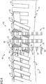
FIG 4 bis 7 ist ein Ausschnitt des ersten Aktivteils 12 mit dem ersten Aktivteilsegment 22 und dem zweiten Aktivteilsegment 24 dargestellt. In den jeweiligen Aktivteilsegmenten 22, 24 ist, wie bereits anhand vonFIG 3 undFIG 4 beschrieben, ein jeweiliger Wicklungsabschnitt 26, 28 in den jeweiligen Nuten 30, 32 angeordnet. Der erste Wicklungsabschnitt 26 weist dabei das erste Anschlusselement 34 auf, welches in drei Leiter unterteilt ist. Auch der zweite Wicklungsabschnitt 28 weist ein zweites Anschlusselement 40 auf, welches ebenfalls in drei Leiter unterteilt ist. Das zweite Anschlusselement 40, und somit jeder Leiter, umfasst zweite Windungen 42. Jede Windung weist weiterhin zweite Teilleiter 44 auf. In den Ausführungsformen derFIG 4 bis 7 umfasst auch das zweite Anschlusselement 40 vier zweite Windungen 42 mit je drei zweiten Teilleitern 44. - Die erste Stirnseite 48 an dem ersten Ende 46 des ersten Aktivteilsegments 22 und die zweite Stirnseite 52 an dem zweiten Ende 52 des zweiten Aktivteilsegments 24 sind aneinander angrenzend angeordnet.
- Um die Wicklung 14 des ersten Aktivteils 12 umzusetzen, wird in einem Segmentübergangsbereich das erste Anschlusselement 34 mit dem zweiten Anschlusselement 40 verbunden. Dazu werden gemäß einer ersten Ausführungsform (
FIG 4 und5 ) das erste Anschlusselement 34 und das zweite Anschlusselement 40 senkrecht zur Bewegungsrichtung des zweiten Aktivteils (inFIG 4 bis FIG 7 nicht dargestellt) in Überdeckung zueinander, also übereinander, angeordnet. In diesem Fall ist das zweite Anschlusselement 40 über dem ersten Anschlusselement 34 angeordnet. Somit sind auch die jeweiligen Leiter der jeweiligen Anschlusselemente 34, 40 übereinander angeordnet. Wie inFIG 4 und5 gezeigt sind also insgesamt zwei Leiter und somit sechs Windungen übereinander angeordnet. - Anstelle die Anschlusselemente 34, 40 übereinander anzuordnen, können gemäß den
FIG 6 und7 das erste Anschlusselement 34 und das zweite Anschlusselement 40 in Bewegungsrichtung des zweiten Aktivteils parallel nebeneinander angeordnet sein. Dabei sind die jeweiligen Leiter der jeweiligen Anschlusselemente 34, 40 abwechselnd nebeneinander angeordnet. - Sieht das Wicklungssystem der elektrischen Maschine 10 eine Mehrschichtwicklung, beispielsweise in Form einer Dreischichtwicklung oder einer Vierschichtwicklung, vor, so kann auch eine Kombination der ersten und der zweiten Ausführungsform zur Anordnung der Anschlusselemente 34, 40 vorgesehen sein.
- Um den ersten Wicklungsabschnitt 26 und den zweiten Wicklungsabschnitt 28 zu der Wicklung 14 zu verbinden, ist in
FIG 5 anhand von Pfeilen die Anschlussverbindung 58 zwischen den ersten Windungen 36 und den zweiten Windungen 42 verdeutlicht. Darin ist jeweils eine Windung der ersten Windungen 36 mit einer Windung der zweiten Windungen 42 verbunden. InFIG 7 , in der die Anschlusselemente 34, 40 in Bewegungsrichtung nebeneinander angeordnet sind, ist die Anschlussverbindung 58 in Form einer Umrandung dargestellt. Verbunden ist jeweils eine Windung der ersten Windungen 36 mit einer Windung der zweiten Windungen 42. - Die Anschlussverbindung 58 kann für beide Ausführungsformen als lösbare oder unlösbare Anschlussverbindung vorgesehen sein. Als lösbare Anschlussverbindung 58 kann beispielsweise eine Klammerung nach dem Prinzip der Lüsterklemme erfolgen. Für unlösbare Verbindungen kann eine Quetschverbindung oder eine Lötverbindung vorgesehen sein.
- Insgesamt geht somit eine segmentierte Zweischichtwicklung mit Halbspulen für Segmentverbindungen hervor. Bei elektrischen Motoren oder Generatoren mit hoher Baugröße werden aufgrund der Verarbeit- und Transportierbarkeit die Eisenpakete segmentiert. Diese Segmentierbarkeit bietet allerdings für die Wicklungstechnik einige Nachteile, zum Beispiel ist die Verwendung von herkömmlichen Zweischichtwicklungen nicht möglich. Dies führt dann zu besonderen Maßnahmen wie beispielsweise Klappspulen oder Einschichtwicklungen. Bei der Verwendung von Klappspulen-Zweischichtwicklungen sind beim Verbau der Segmente ein aufwendiger Spuleneinbau und -isolierung notwendig. Auch der Tausch von defekten Segmenten ist sehr zeit- und kostenaufwendig. Bei der Verwendung von Einschichtwicklungen sind die Spulendimensionen sehr groß und zusätzlich unterschiedliche Spulenformen notwendig.
- Gemäß der vorliegenden Erfindung werden lediglich im Segmentübergangsbereich anstatt von kompletten Spulen Spulenstäbe verwendet. Diese können dann direkt im Fertigungsprozess mit eingebaut und das Segment vollständig imprägniert werden. Bei der Motor-/Generatormontage müssen dann lediglich die Segmentverbindungen (elektrische Verbindungen) angebracht werden. Wenn diese Verbindungsart zusätzlich noch so gewählt wird, dass sie zerstörungsfrei geöffnet werden kann, kommt als weitere Folge noch der Vorteil der viel einfacheren Segment-Tauschbarkeit hinzu.
Claims (9)
- Elektrische Maschine (10) umfassend:- ein erstes Aktivteil (12),- ein zweites Aktivteil (16), wobei das zweite Aktivteil (16) in Bewegungsrichtung relativ zu dem ersten Aktivteil (12) bewegbar ist, wobei- das erste Aktivteil (12) mindestens ein erstes Aktivteilsegment (22) und mindestens ein zweites Aktivteilsegment (24) umfasst, wobei- das erste Aktivteil (12) mindestens eine Wicklung (14) aufweist, welche einen ersten Wicklungsabschnitt (26) und einen zweiten Wicklungsabschnitt (28) umfasst, wobei- das erste Aktivteilsegment (22) Nuten (30) aufweist, in denen der erste Wicklungsabschnitt (26) angeordnet ist und das zweite Aktivteilsegment (24) Nuten (32) aufweist, in denen der zweite Wicklungsabschnitt (28) angeordnet ist,- der erste Wicklungsabschnitt (26) ein erstes Anschlusselement (34) aufweist, welches an einer ersten Stirnseite (48) des ersten Aktivteilsegments (22) angeordnet ist, wobei- der zweite Wicklungsabschnitt (28) ein zweites Anschlusselement (40) aufweist, welches an einer zweiten Stirnseite (48) des zweiten Aktivteilsegments (24) angeordnet ist, wobei- die erste Stirnseite (48) des ersten Aktivteilsegments (22) und die zweite Stirnseite (52) des zweiten Aktivteilsegments (22) in Bewegungsrichtung des zweiten Aktivteils (16) aneinander angrenzend und parallel zueinander angeordnet sind, wobei- das erste Anschlusselement (34) und das zweite Anschlusselement (40) nebeneinander angeordnet sind, wobei- das erste (34) und das zweite Anschlusselement (40) verbunden sind, wobei- das erste Anschlusselement (34) und das zweite Anschlusselement (40) in Bewegungsrichtung des zweiten Aktivteils (16) nebeneinander oder das erste Anschlusselement (34) und das zweite Anschlusselement (40) in Bewegungsrichtung des zweiten Aktivteils (16) senkrecht zur Bewegungsrichtung des zweiten Aktivteils (16) nebeneinander angeordnet sind,dadurch gekennzeichnet, dass- die mindestens eine Wicklung (14) mehrere Windungen (36, 42), welche mehrere Teilleiter (38,44) aufweist, umfasst, wobei- in einem Segmentübergangsbereich die Windungen mit ihren Teilleitern des ersten Anschlusselements und des zweiten Anschlusselements freiliegen, wobei- die Windungen (36) des ersten Anschlusselements (34) und die Windungen (42) des zweiten Anschlusselements (40) in Bewegungsrichtung des zweiten Aktivteils (16) abwechselnd nebeneinander oder die Windungen (36) des ersten Anschlusselements (34) und die Windungen (42) des zweiten Anschlusselements (40) in Bewegungsrichtung des zweiten Aktivteils (16) senkrecht zur Bewegungsrichtung des zweiten Aktivteils (16) nebeneinander angeordnet sind.
- Elektrische Maschine (10) nach Anspruch 1, dadurch gekennzeichnet, dass die mindestens eine Wicklung (14) als Einschichtwicklung oder als Mehrschichtwicklung ausgebildet ist.
- Elektrische Maschine (10) nach einem der vorhergehenden Ansprüche, dadurch gekennzeichnet , dass das erste Aktivteilsegment (22) und das zweite Aktivteilsegment (24) auf einem Trägerelement angeordnet sind.
- Elektrische Maschine (10) nach einem der vorhergehenden Ansprüche, dadurch gekennzeichnet , dass das erste Anschlusselement (34) und das zweite Anschlusselement (40) mittels einer Anschlussverbindung (58) verbunden sind.
- Elektrische Maschine (10) nach Anspruch 4, dadurch gekennzeichnet, dass die Anschlussverbindung (58) als Quetschverbindung oder als Lötverbindung ausgebildet ist.
- Elektrische Maschine (10) nach einem der vorhergehenden Ansprüche, dadurch gekennzeichnet, dass das erste Anschlusselement (34) und/oder das zweite Anschlusselement (40) mittels eines Isolierelements elektrisch isoliert ist.
- Elektrische Maschine (10) nach Anspruch 6, dadurchgekennzeichnet, dass das Isolierelement als Imprägnierharz und/oder Schrumpfschlauch ausgebildet ist.
- Elektrische Maschine (10) nach einem der vorhergehenden Ansprüche, dadurch gekennzeichnet, dass das zweite Aktivteil (16) als Stator oder als Läufer ausgebildet ist.
- Windkraftanlage mit einer elektrischen Maschine (10) nach einem der vorhergehenden Ansprüche.
Priority Applications (2)
| Application Number | Priority Date | Filing Date | Title |
|---|---|---|---|
| EP15164650.2A EP3086442B1 (de) | 2015-04-22 | 2015-04-22 | Elektrische maschine mit einem ersten aktivteil und einem zweiten aktivteil |
| ES15164650T ES2812575T3 (es) | 2015-04-22 | 2015-04-22 | Máquina eléctrica con una primera parte activa y una segunda parte activa |
Applications Claiming Priority (1)
| Application Number | Priority Date | Filing Date | Title |
|---|---|---|---|
| EP15164650.2A EP3086442B1 (de) | 2015-04-22 | 2015-04-22 | Elektrische maschine mit einem ersten aktivteil und einem zweiten aktivteil |
Publications (2)
| Publication Number | Publication Date |
|---|---|
| EP3086442A1 EP3086442A1 (de) | 2016-10-26 |
| EP3086442B1 true EP3086442B1 (de) | 2020-05-27 |
Family
ID=52991642
Family Applications (1)
| Application Number | Title | Priority Date | Filing Date |
|---|---|---|---|
| EP15164650.2A Active EP3086442B1 (de) | 2015-04-22 | 2015-04-22 | Elektrische maschine mit einem ersten aktivteil und einem zweiten aktivteil |
Country Status (2)
| Country | Link |
|---|---|
| EP (1) | EP3086442B1 (de) |
| ES (1) | ES2812575T3 (de) |
Families Citing this family (1)
| Publication number | Priority date | Publication date | Assignee | Title |
|---|---|---|---|---|
| EP3748814A1 (de) * | 2019-06-07 | 2020-12-09 | Siemens Aktiengesellschaft | Stator für eine rotierende elektrische maschine |
Family Cites Families (6)
| Publication number | Priority date | Publication date | Assignee | Title |
|---|---|---|---|---|
| JP3264912B2 (ja) * | 2000-01-20 | 2002-03-11 | 三菱電機株式会社 | 交流発電機 |
| JP3621653B2 (ja) * | 2001-03-28 | 2005-02-16 | 三菱電機株式会社 | 回転電機の固定子および固定子鉄心並びにその製造方法 |
| KR101161470B1 (ko) * | 2006-05-25 | 2012-07-02 | 미쓰비시덴키 가부시키가이샤 | 회전 전기기기의 고정자 |
| EP2211443B1 (de) * | 2009-01-23 | 2016-05-18 | Siemens Aktiengesellschaft | Herstellung von Segmenten mit speziellen Endspulen zur Verbindung der Segmente |
| KR101224688B1 (ko) * | 2009-12-18 | 2013-01-21 | 도요타지도샤가부시키가이샤 | 스테이터 |
| EP2395632A1 (de) * | 2010-06-10 | 2011-12-14 | Siemens Aktiengesellschaft | Statorsegmenteinheit zum Ausbilden eines ringförmigen Stators |
-
2015
- 2015-04-22 EP EP15164650.2A patent/EP3086442B1/de active Active
- 2015-04-22 ES ES15164650T patent/ES2812575T3/es active Active
Non-Patent Citations (1)
| Title |
|---|
| None * |
Also Published As
| Publication number | Publication date |
|---|---|
| EP3086442A1 (de) | 2016-10-26 |
| ES2812575T3 (es) | 2021-03-17 |
Similar Documents
| Publication | Publication Date | Title |
|---|---|---|
| DE112013003663B4 (de) | Elektrische Rotationsmaschine | |
| DE112014005444B4 (de) | Anker für eine elektrische Maschine | |
| EP3542446B1 (de) | Wellenwicklungsspule für ein statorblechpaket einer elektrischen maschine | |
| EP1974439A1 (de) | Elektrische maschine mit einem dreisträngigen wicklungssystem | |
| EP3149836B1 (de) | Elektrische maschine | |
| DE112018000146T5 (de) | Elektrische Maschine mit einem Stator, der mehrere Anschlussdrähte hat, die von einer gemeinsamen Wicklungsschicht ausgehen | |
| DE102022107057A1 (de) | Motor | |
| DE102013001990A1 (de) | Baugruppenkühlsystem und -Verfahren einer elektrischen Maschine | |
| DE102011120985A1 (de) | Elektrische Maschine mit einem Stator und Wickel- und Kontaktierungsverfahren für eine elektrische Maschine | |
| DE102012214523B4 (de) | Ständer oder Ständersegment einer dynamoelektrischen Maschine mit optimiertem Wickelkopf, dynamoelektrische Maschine und Rohrmühle oder Windkraftgenerator | |
| DE112018000190T5 (de) | Elektrische Maschine mit einem Stator, der mehrlagige Endschlaufen hat | |
| DE102016221043A1 (de) | Modular aufgebauter Stator für einen Elektromotor oder Generator | |
| EP3311469A1 (de) | Formspule, wicklungsaufbau sowie stator eines generators einer windenergieanlage und verfahren zum herstellen eines stators | |
| DE102005018600A1 (de) | Statorspule mit konzentrierter Wicklung für eine rotierende elektrische Maschine | |
| EP3216113A1 (de) | Rotor oder stator mit gestecktem flachem wickelkopf | |
| EP3183799B1 (de) | Aktivteil einer elektrischen maschine | |
| AT524754A1 (de) | Maschinenbauteil | |
| DE102020109482B4 (de) | Verfahren zum Herstellen eines Stators für eine elektrische Maschine, entsprechender Stator sowie Verfahren zum Betreiben einer elektrischen Maschine, entsprechender Stator sowie Verfahren zum Betreiben einer elektrischen Maschine | |
| EP1305867A1 (de) | Wicklungen für elektrische maschinen mit leitern aus litze | |
| EP3086442A1 (de) | Elektrische maschine mit einem ersten aktivteil und einem zweiten aktivteil | |
| EP3207620B1 (de) | Statorsegment für einen hohlzylinderförmigen, segmentierten stator einer elektrischen maschine | |
| DE102021125488A1 (de) | Stator einer elektrischen Rotationsmaschine sowie elektrische Rotationsmaschine | |
| EP2882080B1 (de) | Dynamoelektrische rotatorische Maschine | |
| DE102023205277A1 (de) | Verteilte Wicklung für eine elektrische Maschine in Sternschaltung | |
| WO2023222571A1 (de) | Leistungserzeugende komponente einer elektrischen maschine und wellenwicklung |
Legal Events
| Date | Code | Title | Description |
|---|---|---|---|
| PUAI | Public reference made under article 153(3) epc to a published international application that has entered the european phase |
Free format text: ORIGINAL CODE: 0009012 |
|
| AK | Designated contracting states |
Kind code of ref document: A1 Designated state(s): AL AT BE BG CH CY CZ DE DK EE ES FI FR GB GR HR HU IE IS IT LI LT LU LV MC MK MT NL NO PL PT RO RS SE SI SK SM TR |
|
| AX | Request for extension of the european patent |
Extension state: BA ME |
|
| 17P | Request for examination filed |
Effective date: 20170426 |
|
| RBV | Designated contracting states (corrected) |
Designated state(s): AL AT BE BG CH CY CZ DE DK EE ES FI FR GB GR HR HU IE IS IT LI LT LU LV MC MK MT NL NO PL PT RO RS SE SI SK SM TR |
|
| STAA | Information on the status of an ep patent application or granted ep patent |
Free format text: STATUS: REQUEST FOR EXAMINATION WAS MADE |
|
| RAP1 | Party data changed (applicant data changed or rights of an application transferred) |
Owner name: SIEMENS AKTIENGESELLSCHAFT |
|
| STAA | Information on the status of an ep patent application or granted ep patent |
Free format text: STATUS: EXAMINATION IS IN PROGRESS |
|
| 17Q | First examination report despatched |
Effective date: 20190502 |
|
| GRAP | Despatch of communication of intention to grant a patent |
Free format text: ORIGINAL CODE: EPIDOSNIGR1 |
|
| STAA | Information on the status of an ep patent application or granted ep patent |
Free format text: STATUS: GRANT OF PATENT IS INTENDED |
|
| INTG | Intention to grant announced |
Effective date: 20200117 |
|
| GRAS | Grant fee paid |
Free format text: ORIGINAL CODE: EPIDOSNIGR3 |
|
| GRAA | (expected) grant |
Free format text: ORIGINAL CODE: 0009210 |
|
| STAA | Information on the status of an ep patent application or granted ep patent |
Free format text: STATUS: THE PATENT HAS BEEN GRANTED |
|
| AK | Designated contracting states |
Kind code of ref document: B1 Designated state(s): AL AT BE BG CH CY CZ DE DK EE ES FI FR GB GR HR HU IE IS IT LI LT LU LV MC MK MT NL NO PL PT RO RS SE SI SK SM TR |
|
| REG | Reference to a national code |
Ref country code: GB Ref legal event code: FG4D Free format text: NOT ENGLISH |
|
| REG | Reference to a national code |
Ref country code: CH Ref legal event code: EP |
|
| REG | Reference to a national code |
Ref country code: DE Ref legal event code: R096 Ref document number: 502015012643 Country of ref document: DE |
|
| REG | Reference to a national code |
Ref country code: AT Ref legal event code: REF Ref document number: 1275582 Country of ref document: AT Kind code of ref document: T Effective date: 20200615 |
|
| REG | Reference to a national code |
Ref country code: LT Ref legal event code: MG4D |
|
| PG25 | Lapsed in a contracting state [announced via postgrant information from national office to epo] |
Ref country code: NO Free format text: LAPSE BECAUSE OF FAILURE TO SUBMIT A TRANSLATION OF THE DESCRIPTION OR TO PAY THE FEE WITHIN THE PRESCRIBED TIME-LIMIT Effective date: 20200827 Ref country code: GR Free format text: LAPSE BECAUSE OF FAILURE TO SUBMIT A TRANSLATION OF THE DESCRIPTION OR TO PAY THE FEE WITHIN THE PRESCRIBED TIME-LIMIT Effective date: 20200828 Ref country code: FI Free format text: LAPSE BECAUSE OF FAILURE TO SUBMIT A TRANSLATION OF THE DESCRIPTION OR TO PAY THE FEE WITHIN THE PRESCRIBED TIME-LIMIT Effective date: 20200527 Ref country code: LT Free format text: LAPSE BECAUSE OF FAILURE TO SUBMIT A TRANSLATION OF THE DESCRIPTION OR TO PAY THE FEE WITHIN THE PRESCRIBED TIME-LIMIT Effective date: 20200527 Ref country code: PT Free format text: LAPSE BECAUSE OF FAILURE TO SUBMIT A TRANSLATION OF THE DESCRIPTION OR TO PAY THE FEE WITHIN THE PRESCRIBED TIME-LIMIT Effective date: 20200928 Ref country code: SE Free format text: LAPSE BECAUSE OF FAILURE TO SUBMIT A TRANSLATION OF THE DESCRIPTION OR TO PAY THE FEE WITHIN THE PRESCRIBED TIME-LIMIT Effective date: 20200527 Ref country code: IS Free format text: LAPSE BECAUSE OF FAILURE TO SUBMIT A TRANSLATION OF THE DESCRIPTION OR TO PAY THE FEE WITHIN THE PRESCRIBED TIME-LIMIT Effective date: 20200927 |
|
| REG | Reference to a national code |
Ref country code: NL Ref legal event code: MP Effective date: 20200527 |
|
| PG25 | Lapsed in a contracting state [announced via postgrant information from national office to epo] |
Ref country code: HR Free format text: LAPSE BECAUSE OF FAILURE TO SUBMIT A TRANSLATION OF THE DESCRIPTION OR TO PAY THE FEE WITHIN THE PRESCRIBED TIME-LIMIT Effective date: 20200527 Ref country code: RS Free format text: LAPSE BECAUSE OF FAILURE TO SUBMIT A TRANSLATION OF THE DESCRIPTION OR TO PAY THE FEE WITHIN THE PRESCRIBED TIME-LIMIT Effective date: 20200527 Ref country code: BG Free format text: LAPSE BECAUSE OF FAILURE TO SUBMIT A TRANSLATION OF THE DESCRIPTION OR TO PAY THE FEE WITHIN THE PRESCRIBED TIME-LIMIT Effective date: 20200827 Ref country code: LV Free format text: LAPSE BECAUSE OF FAILURE TO SUBMIT A TRANSLATION OF THE DESCRIPTION OR TO PAY THE FEE WITHIN THE PRESCRIBED TIME-LIMIT Effective date: 20200527 |
|
| PG25 | Lapsed in a contracting state [announced via postgrant information from national office to epo] |
Ref country code: AL Free format text: LAPSE BECAUSE OF FAILURE TO SUBMIT A TRANSLATION OF THE DESCRIPTION OR TO PAY THE FEE WITHIN THE PRESCRIBED TIME-LIMIT Effective date: 20200527 Ref country code: NL Free format text: LAPSE BECAUSE OF FAILURE TO SUBMIT A TRANSLATION OF THE DESCRIPTION OR TO PAY THE FEE WITHIN THE PRESCRIBED TIME-LIMIT Effective date: 20200527 |
|
| PG25 | Lapsed in a contracting state [announced via postgrant information from national office to epo] |
Ref country code: EE Free format text: LAPSE BECAUSE OF FAILURE TO SUBMIT A TRANSLATION OF THE DESCRIPTION OR TO PAY THE FEE WITHIN THE PRESCRIBED TIME-LIMIT Effective date: 20200527 Ref country code: IT Free format text: LAPSE BECAUSE OF FAILURE TO SUBMIT A TRANSLATION OF THE DESCRIPTION OR TO PAY THE FEE WITHIN THE PRESCRIBED TIME-LIMIT Effective date: 20200527 Ref country code: SM Free format text: LAPSE BECAUSE OF FAILURE TO SUBMIT A TRANSLATION OF THE DESCRIPTION OR TO PAY THE FEE WITHIN THE PRESCRIBED TIME-LIMIT Effective date: 20200527 Ref country code: RO Free format text: LAPSE BECAUSE OF FAILURE TO SUBMIT A TRANSLATION OF THE DESCRIPTION OR TO PAY THE FEE WITHIN THE PRESCRIBED TIME-LIMIT Effective date: 20200527 Ref country code: CZ Free format text: LAPSE BECAUSE OF FAILURE TO SUBMIT A TRANSLATION OF THE DESCRIPTION OR TO PAY THE FEE WITHIN THE PRESCRIBED TIME-LIMIT Effective date: 20200527 Ref country code: DK Free format text: LAPSE BECAUSE OF FAILURE TO SUBMIT A TRANSLATION OF THE DESCRIPTION OR TO PAY THE FEE WITHIN THE PRESCRIBED TIME-LIMIT Effective date: 20200527 |
|
| PG25 | Lapsed in a contracting state [announced via postgrant information from national office to epo] |
Ref country code: PL Free format text: LAPSE BECAUSE OF FAILURE TO SUBMIT A TRANSLATION OF THE DESCRIPTION OR TO PAY THE FEE WITHIN THE PRESCRIBED TIME-LIMIT Effective date: 20200527 Ref country code: SK Free format text: LAPSE BECAUSE OF FAILURE TO SUBMIT A TRANSLATION OF THE DESCRIPTION OR TO PAY THE FEE WITHIN THE PRESCRIBED TIME-LIMIT Effective date: 20200527 |
|
| REG | Reference to a national code |
Ref country code: DE Ref legal event code: R097 Ref document number: 502015012643 Country of ref document: DE |
|
| REG | Reference to a national code |
Ref country code: CH Ref legal event code: NV Representative=s name: SIEMENS SCHWEIZ AG, CH |
|
| REG | Reference to a national code |
Ref country code: ES Ref legal event code: FG2A Ref document number: 2812575 Country of ref document: ES Kind code of ref document: T3 Effective date: 20210317 |
|
| PLBE | No opposition filed within time limit |
Free format text: ORIGINAL CODE: 0009261 |
|
| STAA | Information on the status of an ep patent application or granted ep patent |
Free format text: STATUS: NO OPPOSITION FILED WITHIN TIME LIMIT |
|
| 26N | No opposition filed |
Effective date: 20210302 |
|
| PG25 | Lapsed in a contracting state [announced via postgrant information from national office to epo] |
Ref country code: SI Free format text: LAPSE BECAUSE OF FAILURE TO SUBMIT A TRANSLATION OF THE DESCRIPTION OR TO PAY THE FEE WITHIN THE PRESCRIBED TIME-LIMIT Effective date: 20200527 |
|
| PGFP | Annual fee paid to national office [announced via postgrant information from national office to epo] |
Ref country code: GB Payment date: 20210504 Year of fee payment: 7 |
|
| PG25 | Lapsed in a contracting state [announced via postgrant information from national office to epo] |
Ref country code: MC Free format text: LAPSE BECAUSE OF FAILURE TO SUBMIT A TRANSLATION OF THE DESCRIPTION OR TO PAY THE FEE WITHIN THE PRESCRIBED TIME-LIMIT Effective date: 20200527 |
|
| PG25 | Lapsed in a contracting state [announced via postgrant information from national office to epo] |
Ref country code: LU Free format text: LAPSE BECAUSE OF NON-PAYMENT OF DUE FEES Effective date: 20210422 |
|
| REG | Reference to a national code |
Ref country code: BE Ref legal event code: MM Effective date: 20210430 |
|
| PG25 | Lapsed in a contracting state [announced via postgrant information from national office to epo] |
Ref country code: FR Free format text: LAPSE BECAUSE OF NON-PAYMENT OF DUE FEES Effective date: 20210430 Ref country code: LI Free format text: LAPSE BECAUSE OF NON-PAYMENT OF DUE FEES Effective date: 20210430 Ref country code: CH Free format text: LAPSE BECAUSE OF NON-PAYMENT OF DUE FEES Effective date: 20210430 |
|
| PG25 | Lapsed in a contracting state [announced via postgrant information from national office to epo] |
Ref country code: IE Free format text: LAPSE BECAUSE OF NON-PAYMENT OF DUE FEES Effective date: 20210422 |
|
| REG | Reference to a national code |
Ref country code: AT Ref legal event code: MM01 Ref document number: 1275582 Country of ref document: AT Kind code of ref document: T Effective date: 20210422 |
|
| PG25 | Lapsed in a contracting state [announced via postgrant information from national office to epo] |
Ref country code: BE Free format text: LAPSE BECAUSE OF NON-PAYMENT OF DUE FEES Effective date: 20210430 |
|
| PG25 | Lapsed in a contracting state [announced via postgrant information from national office to epo] |
Ref country code: AT Free format text: LAPSE BECAUSE OF NON-PAYMENT OF DUE FEES Effective date: 20210422 |
|
| GBPC | Gb: european patent ceased through non-payment of renewal fee |
Effective date: 20220422 |
|
| PG25 | Lapsed in a contracting state [announced via postgrant information from national office to epo] |
Ref country code: GB Free format text: LAPSE BECAUSE OF NON-PAYMENT OF DUE FEES Effective date: 20220422 |
|
| PG25 | Lapsed in a contracting state [announced via postgrant information from national office to epo] |
Ref country code: HU Free format text: LAPSE BECAUSE OF FAILURE TO SUBMIT A TRANSLATION OF THE DESCRIPTION OR TO PAY THE FEE WITHIN THE PRESCRIBED TIME-LIMIT; INVALID AB INITIO Effective date: 20150422 |
|
| P01 | Opt-out of the competence of the unified patent court (upc) registered |
Effective date: 20230510 |
|
| PG25 | Lapsed in a contracting state [announced via postgrant information from national office to epo] |
Ref country code: CY Free format text: LAPSE BECAUSE OF FAILURE TO SUBMIT A TRANSLATION OF THE DESCRIPTION OR TO PAY THE FEE WITHIN THE PRESCRIBED TIME-LIMIT Effective date: 20200527 |
|
| PG25 | Lapsed in a contracting state [announced via postgrant information from national office to epo] |
Ref country code: MK Free format text: LAPSE BECAUSE OF FAILURE TO SUBMIT A TRANSLATION OF THE DESCRIPTION OR TO PAY THE FEE WITHIN THE PRESCRIBED TIME-LIMIT Effective date: 20200527 |
|
| PG25 | Lapsed in a contracting state [announced via postgrant information from national office to epo] |
Ref country code: TR Free format text: LAPSE BECAUSE OF FAILURE TO SUBMIT A TRANSLATION OF THE DESCRIPTION OR TO PAY THE FEE WITHIN THE PRESCRIBED TIME-LIMIT Effective date: 20200527 |
|
| PG25 | Lapsed in a contracting state [announced via postgrant information from national office to epo] |
Ref country code: MT Free format text: LAPSE BECAUSE OF FAILURE TO SUBMIT A TRANSLATION OF THE DESCRIPTION OR TO PAY THE FEE WITHIN THE PRESCRIBED TIME-LIMIT Effective date: 20200527 |
|
| REG | Reference to a national code |
Ref country code: ES Ref legal event code: PC2A Owner name: INNOMOTICS GMBH Effective date: 20241115 |
|
| PGFP | Annual fee paid to national office [announced via postgrant information from national office to epo] |
Ref country code: DE Payment date: 20250429 Year of fee payment: 11 |
|
| PGFP | Annual fee paid to national office [announced via postgrant information from national office to epo] |
Ref country code: ES Payment date: 20250513 Year of fee payment: 11 |
|
| REG | Reference to a national code |
Ref country code: DE Ref legal event code: R081 Ref document number: 502015012643 Country of ref document: DE Owner name: INNOMOTICS GMBH, DE Free format text: FORMER OWNER: SIEMENS AKTIENGESELLSCHAFT, 80333 MUENCHEN, DE |