EP3086291B1 - Vorrichtung und verfahren zur erstellung eines models für den nachfolgenden 3d-druck - Google Patents
Vorrichtung und verfahren zur erstellung eines models für den nachfolgenden 3d-druck Download PDFInfo
- Publication number
- EP3086291B1 EP3086291B1 EP16160004.4A EP16160004A EP3086291B1 EP 3086291 B1 EP3086291 B1 EP 3086291B1 EP 16160004 A EP16160004 A EP 16160004A EP 3086291 B1 EP3086291 B1 EP 3086291B1
- Authority
- EP
- European Patent Office
- Prior art keywords
- values
- model
- virtual environment
- game
- user
- Prior art date
- Legal status (The legal status is an assumption and is not a legal conclusion. Google has not performed a legal analysis and makes no representation as to the accuracy of the status listed.)
- Active
Links
Images


Classifications
-
- A—HUMAN NECESSITIES
- A63—SPORTS; GAMES; AMUSEMENTS
- A63F—CARD, BOARD, OR ROULETTE GAMES; INDOOR GAMES USING SMALL MOVING PLAYING BODIES; VIDEO GAMES; GAMES NOT OTHERWISE PROVIDED FOR
- A63F13/00—Video games, i.e. games using an electronically generated display having two or more dimensions
- A63F13/85—Providing additional services to players
-
- G—PHYSICS
- G06—COMPUTING OR CALCULATING; COUNTING
- G06T—IMAGE DATA PROCESSING OR GENERATION, IN GENERAL
- G06T17/00—Three-dimensional [3D] modelling for computer graphics
- G06T17/10—Constructive solid geometry [CSG] using solid primitives, e.g. cylinders, cubes
-
- G—PHYSICS
- G05—CONTROLLING; REGULATING
- G05B—CONTROL OR REGULATING SYSTEMS IN GENERAL; FUNCTIONAL ELEMENTS OF SUCH SYSTEMS; MONITORING OR TESTING ARRANGEMENTS FOR SUCH SYSTEMS OR ELEMENTS
- G05B19/00—Program-control systems
- G05B19/02—Program-control systems electric
- G05B19/18—Numerical control [NC], i.e. automatically operating machines, in particular machine tools, e.g. in a manufacturing environment, so as to execute positioning, movement or co-ordinated operations by means of program data in numerical form
- G05B19/4097—Numerical control [NC], i.e. automatically operating machines, in particular machine tools, e.g. in a manufacturing environment, so as to execute positioning, movement or co-ordinated operations by means of program data in numerical form characterised by using design data to control NC machines, e.g. CAD/CAM
- G05B19/4099—Surface or curve machining, making three-dimensional [3D] objects, e.g. desktop manufacturing
-
- A—HUMAN NECESSITIES
- A63—SPORTS; GAMES; AMUSEMENTS
- A63F—CARD, BOARD, OR ROULETTE GAMES; INDOOR GAMES USING SMALL MOVING PLAYING BODIES; VIDEO GAMES; GAMES NOT OTHERWISE PROVIDED FOR
- A63F13/00—Video games, i.e. games using an electronically generated display having two or more dimensions
- A63F13/20—Input arrangements for video game devices
- A63F13/21—Input arrangements for video game devices characterised by their sensors, purposes or types
- A63F13/213—Input arrangements for video game devices characterised by their sensors, purposes or types comprising photodetecting means, e.g. cameras, photodiodes or infrared cells
-
- A—HUMAN NECESSITIES
- A63—SPORTS; GAMES; AMUSEMENTS
- A63F—CARD, BOARD, OR ROULETTE GAMES; INDOOR GAMES USING SMALL MOVING PLAYING BODIES; VIDEO GAMES; GAMES NOT OTHERWISE PROVIDED FOR
- A63F13/00—Video games, i.e. games using an electronically generated display having two or more dimensions
- A63F13/25—Output arrangements for video game devices
-
- A—HUMAN NECESSITIES
- A63—SPORTS; GAMES; AMUSEMENTS
- A63F—CARD, BOARD, OR ROULETTE GAMES; INDOOR GAMES USING SMALL MOVING PLAYING BODIES; VIDEO GAMES; GAMES NOT OTHERWISE PROVIDED FOR
- A63F13/00—Video games, i.e. games using an electronically generated display having two or more dimensions
- A63F13/60—Generating or modifying game content before or while executing the game program, e.g. authoring tools specially adapted for game development or game-integrated level editor
- A63F13/63—Generating or modifying game content before or while executing the game program, e.g. authoring tools specially adapted for game development or game-integrated level editor by the player, e.g. authoring using a level editor
-
- B—PERFORMING OPERATIONS; TRANSPORTING
- B33—ADDITIVE MANUFACTURING TECHNOLOGY
- B33Y—ADDITIVE MANUFACTURING, i.e. MANUFACTURING OF THREE-DIMENSIONAL [3D] OBJECTS BY ADDITIVE DEPOSITION, ADDITIVE AGGLOMERATION OR ADDITIVE LAYERING, e.g. BY 3D PRINTING, STEREOLITHOGRAPHY OR SELECTIVE LASER SINTERING
- B33Y30/00—Apparatus for additive manufacturing; Details thereof or accessories therefor
-
- B—PERFORMING OPERATIONS; TRANSPORTING
- B33—ADDITIVE MANUFACTURING TECHNOLOGY
- B33Y—ADDITIVE MANUFACTURING, i.e. MANUFACTURING OF THREE-DIMENSIONAL [3D] OBJECTS BY ADDITIVE DEPOSITION, ADDITIVE AGGLOMERATION OR ADDITIVE LAYERING, e.g. BY 3D PRINTING, STEREOLITHOGRAPHY OR SELECTIVE LASER SINTERING
- B33Y50/00—Data acquisition or data processing for additive manufacturing
-
- B—PERFORMING OPERATIONS; TRANSPORTING
- B33—ADDITIVE MANUFACTURING TECHNOLOGY
- B33Y—ADDITIVE MANUFACTURING, i.e. MANUFACTURING OF THREE-DIMENSIONAL [3D] OBJECTS BY ADDITIVE DEPOSITION, ADDITIVE AGGLOMERATION OR ADDITIVE LAYERING, e.g. BY 3D PRINTING, STEREOLITHOGRAPHY OR SELECTIVE LASER SINTERING
- B33Y80/00—Products made by additive manufacturing
-
- G—PHYSICS
- G06—COMPUTING OR CALCULATING; COUNTING
- G06T—IMAGE DATA PROCESSING OR GENERATION, IN GENERAL
- G06T17/00—Three-dimensional [3D] modelling for computer graphics
-
- G—PHYSICS
- G06—COMPUTING OR CALCULATING; COUNTING
- G06T—IMAGE DATA PROCESSING OR GENERATION, IN GENERAL
- G06T19/00—Manipulating three-dimensional [3D] models or images for computer graphics
- G06T19/20—Editing of three-dimensional [3D] images, e.g. changing shapes or colours, aligning objects or positioning parts
-
- G—PHYSICS
- G05—CONTROLLING; REGULATING
- G05B—CONTROL OR REGULATING SYSTEMS IN GENERAL; FUNCTIONAL ELEMENTS OF SUCH SYSTEMS; MONITORING OR TESTING ARRANGEMENTS FOR SUCH SYSTEMS OR ELEMENTS
- G05B2219/00—Program-control systems
- G05B2219/30—Nc systems
- G05B2219/49—Nc machine tool, till multiple
- G05B2219/49007—Making, forming 3-D object, model, surface
-
- G—PHYSICS
- G05—CONTROLLING; REGULATING
- G05B—CONTROL OR REGULATING SYSTEMS IN GENERAL; FUNCTIONAL ELEMENTS OF SUCH SYSTEMS; MONITORING OR TESTING ARRANGEMENTS FOR SUCH SYSTEMS OR ELEMENTS
- G05B2219/00—Program-control systems
- G05B2219/30—Nc systems
- G05B2219/49—Nc machine tool, till multiple
- G05B2219/49018—Laser sintering of powder in layers, selective laser sintering SLS
-
- G—PHYSICS
- G06—COMPUTING OR CALCULATING; COUNTING
- G06T—IMAGE DATA PROCESSING OR GENERATION, IN GENERAL
- G06T15/00—Three-dimensional [3D] image rendering
Definitions
- the present invention relates to a device and method of generating a model for subsequent 3D printing.
- 3D printing is a means of volumetric printing, where instead of depositing two-dimensional pixels on a flat surface, the printer deposits three-dimensional voxels within a volume.
- the printer deposits three-dimensional voxels within a volume.
- technologies to achieve this including the use of lasers to melt and fuse materials such as metal powder in incremental layers to build a structure, or the use of a high-temperature print-head to deposit small droplets of plastic that cool and harden to build up a 3D model.
- the design for such a 3D model is typically generated in a computer-aided design program, in which a user defines surfaces and volumes of a virtual model.
- a drawing list is then generated by the program specifying the order in which to fuse or deposit materials to render the virtual model using the 3D printer.
- the present invention aims to provide such a new use for 3D printers.
- a computer-implemented method of generating a model for subsequent 3D printing is provided according to claim 1
- a videogame hosting device is provided according to claim 8.
- a device and method of selecting an object from a videogame for 3D printing are disclosed.
- a number of specific details are presented in order to provide a thorough understanding of the embodiments of the present invention. It will be apparent, however, to a person skilled in the art that these specific details need not be employed to practice the present invention. Conversely, specific details known to the person skilled in the art are omitted for the purposes of clarity where appropriate.
- an entertainment device is operably coupled to a 3D printer.
- the entertainment device is arranged in operation to capture snapshots of videogame play for replication by the 3D printer, as explained later herein.
- An example of a suitable entertainment device is the Sony® Playstation 4® device.
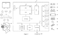
- FIG 1 schematically illustrates the overall system architecture of the Sony® PlayStation 4® entertainment device.
- a system unit 10 is provided, with various peripheral devices connectable to the system unit.
- the system unit 10 comprises an accelerated processing unit (APU) 20 being a single chip that in turn comprises a central processing unit (CPU) 20A and a graphics processing unit (GPU) 20B.
- the APU 20 has access to a random access memory (RAM) unit 22.
- RAM random access memory
- the APU 20 communicates with a bus 40, optionally via an I/O bridge 24, which may be a discreet component or part of the APU 20.
- bus 40 Connected to the bus 40 are data storage components such as a hard disk drive 37, and a Blu-ray ® drive 36 operable to access data on compatible optical discs 36A. Additionally the RAM unit 22 may communicate with the bus 40.
- auxiliary processor 38 is also connected to the bus 40.
- the auxiliary processor 38 may be provided to run or support the operating system.
- the system unit 10 communicates with peripheral devices as appropriate via an audio/visual input port 31, an Ethernet ® port 32, a Bluetooth ® wireless link 33, a Wi-Fi ® wireless link 34, or one or more universal serial bus (USB) ports 35. Audio and video may be output via an AV output 39, such as an HDMI port.
- the peripheral devices may include a monoscopic or stereoscopic video camera 41 such as the PlayStation Eye ® or PS Camera ®; wand-style videogame controllers 42 such as the PlayStation Move ® and conventional handheld videogame controllers 43 such as the DualShock 4 ®; portable entertainment devices 44 such as the PlayStation Portable ® device and PlayStation Vita ® device; a keyboard 45 and/or a mouse 46; a media controller 47, for example in the form of a remote control; and a headset 48.
- Other peripheral devices may similarly be considered such as a phone or tablet, printer, or a 3D printer (not shown).
- the GPU 20B optionally in conjunction with the CPU 20A, generates video images and audio for output via the AV output 39.
- the audio may be generated in conjunction with or instead by an audio processor (not shown).
- the video and optionally the audio may be presented to a television 51. Where supported by the television, the video may be stereoscopic.
- the audio may be presented to a home cinema system 52 in one of a number of formats such as stereo, 5.1 surround sound or 7.1 surround sound.
- Video and audio may likewise be presented to a head mounted display unit 53 worn by a user 60.
- the head mounted display unit may have integral headphones, attachable headphones / earbuds, or rely on separate audio being supplied to the user.
- the CPU 20A may comprise two 64-bit quad core modules, based for example on the 'Jaguar' CPU architecture by AMD ®, for a total of eight cores. Each core may use a base clock speed of 1.6 GHz.
- the GPU 20B may comprise 18 compute units each comprising 64 cores, for a total of 1152 cores.
- the GPU may be based for example on the Radeon ® GCN architecture by AMD ®.
- the GPU cores may be used for graphics, physics calculations, and/or general-purpose processing.
- the system RAM 22 may comprise 8GB RAM, for example in 16 blocks of 512MB GDDR5 unified system memory, and is shared by the CPU and GPU.
- the hard disk may be a 500 GB hard drive.
- the hard drive is mounted so as to be replaceable by a user of the system unit.
- the Blu-ray ® drive may read data from Blu-ray discs at multiples of the standard reading speed.
- the Blu-ray drive may be operably coupled to a hardware-implemented so-called 'zlib' decompression module.
- the auxiliary processor may be provided with its own local memory, such as for example 256 MB of DDR3 SDRAM.
- the system unit 10 may comprise 802.11 b/g/n Wi-Fi® 34; 10Base-T, 100BASE-TX and 1000BASE-T Ethernet ® 32; Bluetooth 2.1 ® 33 and one or more USB 3.0 ports 35.
- the system unit may receive video and optionally audio via AV input 31.
- the system unit may output video and optionally audio via AV output 39 or via Bluetooth ®, Wi-Fi ® or USB.
- the system unit is typically provided with at least one hand-held controller 43 such as the DualShock 4 ®.
- This controller may be used to interact with user interfaces presented by the system unit that are associated with the operating system and/or a particular game or application being run by the system unit.
- the user may also interact with the system unit using a video camera 41 such as the PlayStation Eye ®.
- a video camera 41 such as the PlayStation Eye ®.
- This may provide monoscopic or stereoscopic video images to the system unit 10 via for example AV input 31. Where these images capture some or all of the user, the user may enact gestures, facial expressions or speech as appropriate to interact with the currently presented user interface.
- a controller designed to assist with camera-based user interaction such as the PlayStation Move ® 42
- This controller has a wand form factor and an illuminated region that facilitates detection of the controller within a captured video image. Illuminated regions may similarly be provided on other controllers 43, such as on the DualShock 4 ® device.
- Both kinds of controller comprise motion sensors to detect transverse movement along three axes and rotational movement around three axes, and wireless communication means (such as Bluetooth®) to convey movement data to the system unit.
- wireless communication means such as Bluetooth®
- Such controls can also receive control data from the system unit to enact functions such as a rumble effect, or to change the colour or brightness of the illuminated region, where these are supported by the controller.
- the system unit may also communicate with a portable entertainment device 44.
- the portable entertainment device 44 will comprise its own set of control inputs and audio/visual outputs. Consequently, in a 'remote play' mode some or all of the portable entertainment device's inputs may be relayed as inputs to the system unit 10, whilst video and/or audio outputs from the system unit 10 may be relayed to the portable entertainment device for use with its own audio/visual outputs.
- Communication may be wireless (e.g. via Bluetooth ® or Wi-Fi ®) or via a USB cable.
- peripherals that may interact with the system unit 10, via either wired or wireless means, include a keyboard 45, a mouse 46, a media controller 47, and a headset 48.
- the headset may comprise one or two speakers, and optionally a microphone.
- the GPU typically generates a 1080p high definition image to the AV output 39.
- the frame rate of these images may vary.
- the image is typically conveyed to a television 51 via a standard HDMI connection, optionally via an AV receiver (not shown).
- the 1080p high definition may be formatted as a stereoscopic image for example using a left-right side-by-side format.
- the television will then split the image in two and interpolate each half to full width for respective presentation to the user's left and right eyes, either by use of specially adapted glasses or by use of directed light paths from an autostereoscopic display.
- the APU 20 generates audio for output via the AV output 39.
- the audio signal is typically in a stereo format or one of several surround sound formats. Again this is typically conveyed to the television 51 via an HDMI standard connection. Alternatively or in addition, it may be conveyed to an AV receiver (not shown), which decodes the audio signal format and presented to a home cinema system 52. Audio may also be provided via wireless link to the headset 48 or to the hand-held controller 43. The hand held controller may then provide an audio jack to enable headphones or a headset to be connected to it.
- the video and optionally audio may be conveyed to a head mounted display 53 such as the Sony Morpheus ® display.
- the head mounted display typically comprises two small display units respectively mounted in front of the user's eyes, optionally in conjunction with suitable optics to enable the user to focus on the display units.
- one or more display sources may be mounted to the side of the user's head and operably coupled to a light guide to respectively present the or each displayed image to the user's eyes.
- one or more display sources may be mounted above the user's eyes and presented to the user via mirrors or half mirrors.
- the display source may be a mobile phone or portable entertainment device 44, optionally displaying a split screen output with left and right portions of the screen displaying respective imagery for the left and right eyes of the user.
- Their head mounted display may comprise integrated headphones, or provide connectivity to headphones.
- the mounted display may comprise an integrated microphone or provide connectivity to a microphone.
- the entertainment device defaults to an operating system such as Orbis OS ®, a variant of FreeBSD 9.0.
- the operating system may run on the CPU 20A, the auxiliary processor 38, or a mixture of the two.
- the operating system provides the user with a graphical user interface such as the PlayStation Dynamic Menu. The menu allows the user to access operating system features and to select games and optionally other content.
- respective users Upon start-up, respective users are asked to select their respective accounts using their respective controllers, so that optionally in-game achievements can be subsequently accredited to the correct users.
- New users can set up a new account. Users with an account primarily associated with a different entertainment device can use that account in a guest mode on the current entertainment device.
- the OS may provide a welcome screen displaying information about new games or other media, and recently posted activities by friends associated with the first user account.
- the OS then provides a series of icons for the user to select amongst, for example in the form of two parallel horizontal rows.
- the content of the top row may be fixed and relate to operating system features, whilst the bottom row may be at least in part dynamically assembled to relate to recent activities, such as providing launch icons for the most recently played or downloaded games.
- the top row of icons may provide access to screens relating to an online store; notifications; friends; text chat; voice chat; user account profile; trophies; system settings; and/or power management.
- the online store may provide access to games and media for download to the entertainment device.
- a welcome screen may highlight featured content.
- content or prices exclusive to that service may be provided in addition to standard content or prices.
- the store may also provide means to pay money into an online account for purchasing content, and may provide a record of purchases, enabling a user to download a purchased item of content at a later date or multiple times (for example after choosing to swap to a larger hard disk).
- the notifications screen provides information about new trophies; game alerts (for example relating to special online events); game invites from friends; download and/or update status for content, and upload status for content being shared.
- the friends screen allows a user to view all their friends or filter them according to who is currently online; additionally a user can review a list of other users they have met within games or other multi-user applications of the entertainment device, and optionally send such a user a friend request or conversely block a user to avoid encountering them again.
- a user can request that a friend allow them to see their real name; subsequently they can also contact this friend via other social media such as Facebook®, optionally via a built-in interface.
- Text chat provides a means to send messages to friends and other users of the entertainment device's network.
- voice chat provides a means to invite a group of friends to share an audio channel over the entertainment device's network so that they can chat to each other, for example whilst playing a game.
- the account user profile screen allows a user to review statistics relating to their activities with the entertainment device.
- the screen also provides means to configure the user's appearance on the network, such as selecting an avatar to be associated with their username.
- the trophy screen allows a user to view their trophies and in-game progress; trophies may be organised on a game-by-game basis. A user's trophies or other performance statistics may be compared with those of their friends to identify the friend with the closest better performance statistic in a game, so as to encourage the user to play further or improve their play of the game.
- the system settings screen provides access to further menus enabling the user to configure aspects of the operating system. These include setting up an entertainment device network account, and network settings for wired or wireless communication with the Internet; the ability to select which notification types the user will receive elsewhere within the user interface; login preferences such as nominating a primary account to automatically log into on start-up, or the use of face recognition to select a user account where the video camera 41 is connected to the entertainment device; parental controls, for example to set a maximum playing time and/or an age rating for particular user accounts; save data management to determine where data such as saved games is stored, so that gameplay can be kept local to the device or stored either in cloud storage or on a USB to enable game progress to be transferred between entertainment devices; system storage management to enable the user to determine how their hard disk is being used by games and hence decide whether or not a game should be deleted; software update management to select whether or not updates should be automatic; audio and video settings to provide manual input regarding screen resolution or audio format where these cannot be automatically detected; connection settings for any companion applications run on other devices such as mobile phones
- the entertainment device network account may be set up to include the user's real name and optionally other personal details, bank details for online payments, an indication of whether the current entertainment device is the primary entertainment device associated with the user account, and the ability to selectively transfer licenses between entertainment devices where the user account is associated. Additionally a user may provide user account information for other services for which access may be integrated into the operating system, such as Facebook® and Twitter®; this enables easy sharing of the user's activities with friends who may not be on the entertainment device network but are on other social networks.
- the power management icon allows the user to turn the device off.
- it may provide a timer for the entertainment device to turn off within a after a predetermined time unless the user intervenes.
- the bottom row of the menu may show icons for recently played games, enabling quick access.
- selection of a game icon provides a summary of game progress and any relevant statistics, and where appropriate information such as progress and commentary from friends who have also played or are playing the game.
- Other information regarding the game may also be provided such as details of recently applied updates, or links to downloadable content associated with the game that is available in the online store.
- the bottom row may also provide access to other media sources such as a web browser, television and music media applications, and any live streaming service provided by the entertainment device network. Additionally an icon may be provided to access the full library of content on the device, such as games that have not been recently played.
- the user interface of the operating system may also receive inputs from specific controls provided on peripherals, such as the hand-held controller 43.
- a button to switch between a currently played game and the operating system interface may be provided.
- a button may be provided to enable sharing of the player's activities with others; this may include taking a screenshot or recording video of the current display, optionally together with audio from a user's headset. Such recordings may be uploaded to social media hubs such as the entertainment device network, Twitch®, Facebook® and Twitter®.
- the entertainment device is operably coupled to a 3D printer.
- SLS selective laser sintering
- stereolithography uses a photo-reactive liquid in conjunction with one or more lasers to harden the liquid at defined points, thereby building the model, again typically in layers. Whilst both of these techniques are envisaged within the scope of embodiments of the present invention, they have the disadvantage of requiring both powerful lasers and large volumes of matrix material in the form of powder or liquid around the model, which make them less practical for domestic use.
- FDM fused deposition modelling
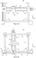
- Figure 2A shows a side elevation of a simple FDM 3D printer 100
- Figure 2B shows a plan view of the same FDM 3D printer.
- the printer 100 comprises a base structure 110 that provides a working surface for assembly of the printed model and support struts 102 upon which a printer frame 120 can be raised and lowered.
- a motor 112Y is coupled to a drive bar 104 comprising a screw thread; a printer frame 120 then comprises a coupling section with a threaded hole and a smooth hole, the threaded hole being engaged with the drive bar and the smooth hole being engaged with one of the support struts.
- the motor 112Y turns the drive bar in a clockwise or anticlockwise direction, the printer frame is moved up or down the drive bar and support strut (i.e. along the y-axis) and hence raises or lowers a printer carriage 130 attached to it.
- the printer frame 120 is typically mounted on four support struts 102.
- a second motor, drive bar and coupling section may be provided at an opposing corner of the frame, to reduce strain on the frame and the motor.
- the printer frame 120 supports the printer carriage 130.
- a motor 112X is coupled to a drive band 122 that is fixed by fixing means 124 to the printer carriage 130.
- the motor 112X rotates the drive band clockwise or anticlockwise, the printer carriage 130 is moved right or left along the printer frame 120 (i.e. along the x-axis) and hence moves an attached printer mechanism 140 laterally.
- the printer carriage 130 supports the printer mechanism 140.
- a motor 112Z is coupled to a drive band 132 that is fixed by fixing means 134 to the printer mechanism 140.
- the motor 112Z rotates the drive band clockwise or anticlockwise, the printer mechanism 140 is moved in or out of a depth direction (i.e. along the z-axis).
- the printer mechanism 140 itself comprises heating means for heating the end of one or more plastic threads fed into the mechanism (not shown), or for heating grains of plastic powder obtained from a hopper on the mechanism (not shown).
- the heating of the plastic or alternatively the release of heated plastic is controlled by instruction from a printer driver.
- a resulting bead or droplet of melted plastic is then deposited onto the working surface 110 of the printer or a partially built model (not shown) as applicable, through the printer head or nozzle 142.
- the printer head can be positioned anywhere within a working volume of the 3D printer using motors 112X, Y, Z, and a droplet of plastic can be deposited at that position, which then cools and hardens to form a voxel of a 3D model.
- a completed 3D model can thus be built from a plurality of such voxels.
- the printer driver itself is a software module in a computer-aided design system that receives model geometry describing the 3D model.
- the printer driver then generates thin slices of the 3D model one voxel thick for each layer in the y direction, and determines the x, z coordinates for each voxel in that layer.
- the printer driver then outputs a sequence of instructions to the printer 100 to move the printer head 142 to the respective x, z coordinate for each voxel in layer y, where the printer mechanism is instructed to heat and/or release a droplet of plastic to form a voxel at that position. In this way the digital 3D model is rebuilt as a physical model by the 3D printer.
- the printer driver is incorporated into the videogame, or the operating system of the entertainment device, or a middleware library of support functions used by either the videogame or the operating system.
- a videogame running on the entertainment device comprises a virtual environment in which typically a plurality of entities or environmental elements are dynamically viewed as the user changes the position of viewpoint and as entities or elements of the game enact scripted activities or react to the user's behaviour, or a mixture of both.
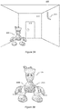
- a simple environment 200 comprising a room 210 with a door 212; on one wall there is mounted a candle in a candleholder 214.
- the player's character 220 here illustrated for example by the fictitious game character Blobman.
- the virtual environment is constructed in 3D from geometry data, typically in the form of polygons defining a surface of an object.
- These polygons may be predefined for example in the case of static objects and background scenery, or may be warped/repositioned or procedurally generated in the case of mobile entities within the environment such as the player's character.
- references herein to 'polygons' encompasses preliminary geometrical features such as vertices, from which polygons are built, where these are used in the graphics pipeline.
- voxel rendering uses equivalent geometric features to describe objects. Hence processes described as applying to polygons may be applied in whole or part to such other geometrical features as appropriate.
- the virtual environment is then prepared for presentation to the user from a selected viewpoint.
- Elements of the environment that have line of sight to the user are patterned with texture information appropriate to the object they represent, and the textured geometry is further processed for lighting effects, such as variations in brightness from virtual light sources, and bump mapping (or similar techniques such as displacement mapping or use of an isosurface) to simulate how the texture should interact with such a virtual light source. Additionally other effects such as volumetric fog and particle effects may be included.
- the final rendered image is then presented to the user, typically via a 2D or 3D television or via a head mounted display.
- an entertainment device such as the PlayStation 4 ® can have a 'share' button on its controller to facilitate a capture of the image presented to the user, which can then be uploaded to a sharing site such as a social media site.
- the user is provided with the option to select a moment within the game from which to create a 3D printed model. In this way, the user can create tangible mementos of their in-game experiences.
- in-game geometry may be suitable to drive a 3D printing process.
- in-game geometry verices, polygons and the like
- simple block-based environment within Minecraft lends itself to being rendered by a 3D printer.
- a virtual environment may comprise several bounding surfaces that have zero thickness, upon which are placed physical objects, some of which may additionally be unstable in the real world.
- An example of such bounding surfaces may be the walls of the room 210 in the virtual environment 200 of Figure 3A .
- supplementary printer geometry is provided that is used to modify elements of the environment that are unsuited to 3D printing.
- the supplementary printer geometry is defined by the game developer in a similar manner to conventional game geometry.
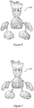
- supplementary printer geometry for the character 'Blobman' may comprise rods 222A,B,C,D to connect the legs and arms to the character's torso, making the modified 3D character 220' a contiguous body suitable for 3D printing.
- the supplementary printer geometry may replicate some or all of the existing in-game geometry in addition to the elements that support 3D printing, or may only comprise the elements that support 3D printing, with the combined supplementary and in-game geometry being used for 3D printing.
- a partial replacement of in-game geometry may be used, for example to replace a sharp point on a sword or a stiletto heel with a rounded or broad surface, either for safety reasons or to provide a better bond for the object to its supporting surface when it is 3D printed.
- the in-game geometry is supplemented by, and optionally at least partially replaced by, supplementary printer geometry for 3D printing that takes account of the physical requirements of the printing process and of the completed model under the effect of gravity.
- the environment is modified using the 3D printing-compatible supplementary printer geometry, before the drawing list required by the printer is output either directly to a printer or to a file for subsequent use by the printer driver.
- supplementary printer geometry for 2D elements of the environment may be defined that has the thickness needed to provide adequate structural support for the environmental feature when 3D printed.
- the 3D model can also be coloured during construction, either by the application of ink or by the selection of different coloured plastics, then the textures used for the video game geometry can also be used to drive the colouring process for the model.
- the textures can also be used for the supplementary printer geometry to the extent that the in-game and supplementary geometries match.
- either supplementary textures may be provided, or textures may be extrapolated from the existing textures, or no texture may be used.
- the texture may be extrapolated from the portion of the environment supporting an element against gravity (e.g. the ground, or in the case of Blobman, from the feet to the torso, and from the torso to the hands and head, respectively), as this is likely to create the most unobtrusive supporting structure within the model.
- the bare plastic or other 3D printer material
- is left exposed making it clear to the viewer that this is a functional support that is not part of the original image. Which approach is preferred may be an artistic decision for the user or developer.
- this supplementary printer geometry may be provided only in key areas of the game, for example where a particular puzzle is solved or a boss has been defeated.
- the option to create a 3D snapshot will thus only be enabled within the supported areas.
- additional 'bonus' geometry may be provided, such as exclusive victory poses that the user can select for their character to use within the 3D printed version of the environment.
- the supplementary printer geometry places a development burden on developers, and imposes a trade-off between the flexibility to print mementos of the in game experience and the amount of additional geometry that needs to be defined to support this ability. It will be preferable to increase the number of environments where this is possible whilst mitigating the burden on the developer.
- the user is again provided with the option to select a moment within the game from which to create a 3D printed model. In this way, the user can create tangible mementos of their in-game experiences.
- the entertainment device when the entertainment device receives an input indicating that a user wishes to create a 3D print of the current scene, the game state is frozen (e.g. paused) so that it can be analysed for 3D printing.
- the in-game geometry which might be considered a likely source of information for a 3D model, may be a mix of polygons, skeletal models, skin models, bump maps and physics derived procedural models or deformations to models, etc., that are typically only combined in one place, and in one format, which is when they are rendered for display on screen.
- a 3D model is constructed for 3D printing using these rendered images in preference to the potentially disparate in-game representations of the virtual environment geometry.
- a single rendered image will typically comprise insufficient information to fully model the virtual environment for 3D printing.
- the entertainment device while the game state is frozen the entertainment device generates a plurality of rendered images of the virtual environment from different viewpoints.
- At least two opposing viewpoints are rendered, with the first viewpoint typically being the one originally displayed to the user. Between the two images, this results in the rendering of most if not all of the elements of the environment culled in the original rendered view.
- three viewpoints are rendered, preferably equally distributed on a plane, with the first viewpoint being the one originally displayed to the user and the plane being horizontally centred on the direction of view of that first viewpoint. Again this results in the rendering of most if not all of the elements of the environment culled in the original rendered view, but is likely to capture more elements of the environment that may have been occluded by objects both in front and behind them and hence not rendered in either of the two viewpoints mentioned above.
- the entertainment device may conduct a 'fly-by' within the environment, capturing N images, where N is for example between 2 and 360.
- N is for example between 2 and 360.
- the number of images captured is a trade-off between fidelity of the eventual model and the memory and processing capacity of the entertainment device needed to analyse the captured images (as discussed later herein).
- one or more viewpoints looking down from above the virtual environment may also be rendered (either as individual images or as part of a flyby sequence) to provide additional detail for those elements of the environment that are substantially parallel to the previously captured viewpoints on a single plane, such as the top surfaces of some environmental features.
- metadata relating to the position and viewing direction of the virtual camera representing the viewpoint for each image is also recorded and associated with the respective image.
- the virtual environment may represent a large area
- the 3-D model will encompass a limited area determined by the size of models that can be generated by a particular 3-D printer and the scale at which the environment is printed.
- the properties of the particular 3-D printer are known if it is in communication with the entertainment device (otherwise, a default model size may be assumed or the user may stipulate a size); similarly the scale at which the environment is printed may be selected by the user or may be automatically determined with reference to a key character within the environment, such as the user's avatar.
- This avatar may be chosen to be a particular size within the final 3-D printer model (as a nonlimiting example, 5 cm tall by default), and the extent of the environment to be printed at the same scale may thus be calculated.
- a 'character print' mode only a particular character, such as the user's avatar, may be printed, without surrounding in-game environmental features. This may be of particular value for cases where the user is allowed to customise their own in-game character, and becomes emotionally attached to it.
- the equidistant distribution of two or more viewpoints may thus be centred on this key character, and may optionally use any in-game camera control logic to determine the necessary direction of view needed to centre the key character within each captured image.
- the centre point of the model can be calculated and the viewpoints can be distributed around it.
- the entertainment device may capture images by selecting sample points on a sphere of predetermined radius, and which is centred on that centre point.
- those sample points that are occluded by an environmental barrier such as a point on the sphere below the ground or inside a mountain
- the sampling scheme may initially select viewpoints on the above mentioned plane comprising the original viewpoint and centre point and parallel to the horizontal axis of the original viewpoint, before optionally selecting one or more viewpoints on the sphere above this plane, and optionally one or more viewpoints on the sphere below this plane.
- the predetermined radius may be equal to the distance between the original viewpoint and the determined centre point of the model, to maintain consistency with the original captured image, or the original image and the subsequent additional image(s) may be re-rendered at a different effective radius, for example a minimum radius at which the field of view of the image encompasses the ground area that will be included in the 3D printed model.
- a minimum radius at which the field of view of the image encompasses the ground area that will be included in the 3D printed model may be constrained to a maximum distance equal to a rendering distance at which the game would select a lower-fidelity model of a key element of the image (such as the user's avatar).
- this may be overridden by a user for aesthetic purposes or because they wish to ensure that a particular environmental feature or combination of features is included in the final model. This may be of particular value for cases where the user is allowed to customise the environment, for example by creating so-called 'mods'.
- the result is a set of images capturing two or more complimentary viewpoints of the virtual environment for a given game state.
- the above image capture procedure may be controlled by the entertainment device.
- the user may capture images of the same scene from one or more different viewpoints by selecting these viewpoints themselves and using a conventional image capture process. These viewpoints may not correspond to the preferred distributions discussed previously herein.
- images of the same scene from different viewpoints can be captured by different users at different times on different entertainment devices; providing a user has access to a pooled set of images (for example if they are posted to an online forum, or are stills extracted from a 'fly-by' video that moves or changes viewpoints, such as may be included in a trailer video for the videogame) then an equivalent set of two or more complementary viewpoints of the virtual environment may be obtained.
- an entertainment device Given these images and optionally associated metadata relating to the viewpoint position and direction, an entertainment device can analyse these images to generate 3-D model data.
- Silhouette analysis uses the edges of objects within the captured images to estimate the object's profile local to that edge.
- the object profile can then be extruded orthogonal to the profile for each viewpoint until it intersects with another extruded profile (typically extruded from another viewpoint), to create an approximation of the object's shape. It will be appreciated that as the number of viewpoints increases according to the scheme described previously herein, each extrusion will subtend a smaller angle around the object, resulting in a more accurate overall model of the object.
- Stereoscopic analysis uses the relative displacement of the same objects within two overlapping viewpoints to calculate their distance from the or each viewpoint. From this information, a depth map can be constructed that is indicative of the 3D shape of the object in the region visible to both viewpoints. Hence again where more viewpoints are available, successive pairs of viewpoints can be used to build a map of the surface of a viewed object.
- this may be estimated by correlating environmental features between images, and selecting viewpoint positions and directions that provide the best correlation for the relative positions of these features.
- silhouette analysis and stereoscopic analysis can be used to complement each other.
- the two techniques can be used to detect errors in each other's models; where the two techniques generate estimates of an object surface that differ by a threshold amount, the estimate that most closely matches an interpolation between nearby estimates of the object surface from the two techniques that are within a threshold agreement may be used, with the other estimate being discarded.
- such areas of the model may also be highlighted for inspection and/or editing by the user prior to printing, as discussed later herein.
- the above techniques are particularly useful where the image data is obtained from third parties (for example from screenshots on a forum), and there is no additional metadata available.
- this depth map is also captured and associated with each image captured by the entertainment device for use in the generation of the 3D model.
- this information can be obtained in a manner that is transparent to the operation of the renderer by copying the so-called z-buffer used when generating the image. Consequently the image capture process does not require modification of a game rendering engine.
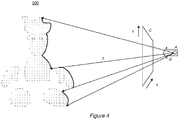
- each pixel is displaced from the position A of the image viewpoint by amount x,y,z in a co-ordinate scheme local to the image (but which may be rotated to a co-ordinate scheme common to the shared virtual modelling space, using known techniques).
- x and y are the pixel co-ordinates in the captured image (represented by notional screen C)
- z is the associated depth or distance value for that pixel from the camera position A. Only one column of pixels (i.e. for a single value of x) have been projected in Figure 4 for clarity, but it will be appreciated that all pixels of the image can be projected in this manner.
- each image will be positioned within the shared virtual modelling space at their correct position in 3D on the surface of a virtual object in the scene, as illustrated in Figure 4 using the example of Blobman.
- the second projected pixel may be discarded or may replace the first pixel.
- pixels are two dimensional objects. Consequently in an embodiment of the present invention, when a pixel from an image is projected to a postion x i , y j , z k in the shared virtual modelling space, in fact a voxel (a typically cubic 3-dimensional pixel) is created at that position, and the colour information associated with the projected pixel is used as the colour information for the voxel.
- a voxel a typically cubic 3-dimensional pixel
- the effect is that a shell of voxels representing the visible surface of the virtual environment is built up by projecting the colour data of the image pixels in each image to x,y,z positions in the shared virtual modelling space.
- this depth information may be estimated using the previously discussed techniques of stereoscopic depth estimation and/or silhouette analysis and surface extrusion. Hence these techniques may also be used to drive the assembly of a voxel shell within a shared model space in the above described manner.
- the resulting shell of voxels can be analysed for integrity. Any gaps in a surface (optionally below a threshold size) may be filled in by interpolation from the surrounding surface.
- a 3D model can be generated for printing.
- the shell can be extruded to a predetermined thickness.
- the extrusion may be performed by adding adjacent voxels to each surface voxel on the side opposite to the side(s) from which they were projected into the shared virtual modelling space (i.e. on the inside or underside of the shell).
- the number of voxels added may be the lesser of M voxels or the number needed to reach an opposite existing surface of an object.
- M may be chosen to result in a thickness responsive to the weight and strength of the material being used to print the model.
- the lowest point within the (now extruded) model can be determined.
- At least two additional points, typically on the underside of the shell, can be extruded further to match the lowest point, thus providing at least three points of support for the physical model.
- these points of support are distributed around a calculated centre of mass of the model.
- a 3D model of the virtual environment can be constructed from plural in-game images that will stay up when physically printed and is viewable from a plurality of angles.
- the model is then sent to a 3D printer driver, which slices the model into layers from the bottom up. These layers are then successively printed by the 3D printer as described previously.
- the voxel shell described previously is modified to take account of physical requirements of the 3D printed model.
- the shell of voxels is extruded to be M voxels thick, to provide some physical strength. This also addresses the problem of 2D objects within the environment, as the shell of voxels corresponding to these objects are extruded in the same as any other element of the shell of voxels.
- procedurally defined modifications to the voxel shell are provided for the purposes of 3D printing. These procedural modifications provide structural strength and/or physical support for some elements of the virtual environment that it would not otherwise be feasible to replicate in a 3D printed model. It will also be appreciated that these procedurally defined modifications can be applied to in-game geometry as well as using supplementary printer geometry.
- references to 'printer geometry' refer to the voxels created to define the 3D model for printing, and examples of procedural supplementary geometry are based on analysis of the voxel shell, it will be appreciated that these may equally refer to in-game geometry (whether partially augmented by supplementary geometry or not).
- Procedurally generated or modified printer geometry are generated by the entertainment device once the initial voxel shell has been generated.
- the voxel shell is analysed to detect whether additional geometry is required, according to several basic rules.
- One analysis step is to detect whether there are unsupported objects within the environment.
- these may be made subject to a de minimis size threshold so that objects below the threshold, such as for example snowflakes, bullets etc., are ignored and subsequently not retained within the 3D model.
- the associated voxels in the voxel shell may be deleted.
- this step may be implemented in a modified rendering process so that these items are never rendered in the first place when collecting images for the model, making the analysis of the images simpler.
- printer geometry for a support structure such as connecting rod may be procedurally generated between the object and a nearby anchor point, the anchor point being a part of the environment ultimately connected to the ground.
- the ground itself can be assumed to be connected to the lowest point of the voxel shell.
- the analysis can proceed from the lowest part of the voxel shell upwards so that unsupported objects can be sequentially supported, enabling them to support subsequent objects in turn.
- a supporting rod will be formed between the base of their foot and the ground by creating a cylinder of voxels, for example M voxels thick by default.
- the thickness of the rod may also be procedurally determined according to basic rules. For a given type of printer, the weight by volume of common 3D printer materials and their compression and bending strengths will be known. In addition, the expected size of the printed model will be known. Accordingly, the entertainment device can estimate the weight of unsupported objects, and calculate the thickness of supporting rod needed to adequately support the object within the model.
- the moment of the unsupported object is a function of its weight multiplied by its distance from the current position along the rod.
- the weight of the connecting rod itself may be a significant proportion of the weight. Consequently the rod may be thicker closer to the anchor point and taper towards the unsupported object as respective parts of the rod support a greater weight at the anchor point than at the unsupported object.
- the above principle can be applied to other parts of the voxel shell; for example a virtual model desk within a game may have legs that are too thin to support the total mass of the desk surface and any objects on the desk. For example, if the desk has a character standing on it, but the desk legs are only a few voxels thick, they may not be strong enough to support the physical model. Accordingly features of the voxel shell can be evaluated to determine the total weight they will be supporting in the model, and where this exceeds a safe margin for the cross sectional area of the voxel shell supporting this weight, this may be thickened by scaling up its cross-section and filling it with voxels.
- the principle may also for example be applied to trees within the environment, where the cumulative weight of branches and the trunk are used to locally modify the geometry of the branches or trunk to make their cross-section larger to accommodate the weight, in those circumstances where the existing geometry is locally insufficient to accommodate the weight when rendered as a 3D model using the particular materials associated with the 3D printer.
- the centre of gravity of the adjusted model may be calculated to detect if it would fall over. If so, then either a support may be moved to restore stability, or optionally the voxel shell may be thickened in one or more selected places to alter the centre of gravity back to a stable position.
- Figure 5A represents a two-dimensional wall from the environment 200, upon which a candle and candlestick are placed within the game.
- Figure 5B then illustrates an extrusion process to extend the wall in a direction normal to the wall plane and opposite to the side from which the image was projected, to procedurally generate geometry describing a wall with a predetermined thickness, for example of M voxels.
- a wall of constant thickness may be unsuitable as the thickness of the wall near the base may be insufficient to adequately support the cumulative weight of the model.
- the thickness of the extrusion increases as a function of cumulative weight, resulting in a step change in thickness at the point of attachment of the candlestick to the wall to provide additional support.
- procedural rules may thicken a region around such points of attachment, such that the wall is thickened slightly before the load of the candlestick is applied to the wall, as illustrated in Figures 5D-E .
- the procedural rules may accommodate the additional mass of the supportive thickening itself when extruding lower portions of the wall.
- the load imposed by the candlestick and the supporting region may be distributed laterally as well as vertically, so that the thickened supporting region splays sideways as it propagates down the wall, as shown in Figure 5E .
- the procedural rules may also interact with additional information provided by a game developer, to assist in generating desirable supplementary geometry automatically.
- the previously noted rule that a connecting rod is procedurally generated between an unsupported object and the nearest anchor point, where the anchor point is a part of the environment ultimately connected to the ground, may result in 3D model of Blobman 220' as illustrated in Figure 6 .
- the procedural rules may attach the character's hand to the only grounded anchor points available, which are the feet; subsequently the torso may be anchored to the closest single anchor point, which is now one of the hands. The result is a structure that, whilst stable, does not conform anatomically to what the user might expect.
- game developers may identify preferred points of connection between elements of the environment in order to guide the procedural generation of connecting rods or other connecting/support structures.
- These points of connection may be defined by use of a reserved value within one or more colour channels, enabling points of connection to be identified by use of a specifically coloured identifying pixel within an image; for example if the value 128 was reserved on the blue channel to denote a connecting point, then this can be used in the example of the Blobman character 220" of Figure 7 to specify where preferred connecting points exist on the model.
- These reserved values are then used within the voxel shell, creating identifiable anchor points for use with the procedural rules.
- matching values in the other two colour channels of the identifying pixel can be used to indicate paired connecting points, so that red and green values in the identifying pixel could be the same for the hand and the torso, causing these to be identified as sections to be connected together.
- artistic control of the placement of connecting structures can be maintained by the developers without the need for separate metadata.
- Blobman this could be used to ensure an anatomically acceptable set of connecting rods, as can be seen in Figure 7 . Meanwhile, the rules for procedural generation of the connecting/support structure will still determine the required cross-section needed to adequately support the printed structure.
- textures may be extrapolated from the existing voxel shell, or a no colour may be specified.
- the colours may be extrapolated from the portion of the structure supporting an element against gravity (e.g. the ground, or in the case of Blobman, from the feet to the torso, and from the torso to the hands and head, respectively), as this is likely to create the most unobtrusive supporting structure within the model.
- the bare plastic or other 3D printer material
- is left exposed making it clear to the viewer that this is a functional support that is not part of the original image. Which approach is preferred may be an artistic decision for the user.
- the pixel resolution of the rendered images may be higher than the voxel resolution of the 3D printer at the scale chosen for printing. Consequently features of the rendered environment may sometimes have a high spatial frequency relative to the voxel resolution of the 3D printer. Accordingly the images may be filtered to a compatible resolution before projection into the shared virtual model space, to remove such high-frequency detail and thereby avoid aliasing effects in the resulting model. In this case, where reserved colour channel values are to be used by procedural rules, these are preserved or reinserted into the lower resolution image after filtration. The depth information may be similarly filtered.
- the above discussion has assumed that a region of the virtual environment displayed to the user will be replicated as a 3D model.
- the user may specify one or more objects in the environment for 3D printing alone; for example, the user may select to just print their avatar, or their avatar and an opponent.
- This selection may be done for example by a user interface for defining a bounding box around the desired object(s), or by a user interface for indicating specific objects within the game environment using a cursor or reticule.
- a default surface such as a flat panel may be generated having an area responsive to the size of the selected object(s).
- the selected object(s) can then be coupled to the support surface using the techniques described herein.
- printer geometry may be transferred to an editing application for the user to preview or modify the model before sending it to the printer.
- an editing application for the user to preview or modify the model before sending it to the printer.
- the editor may likewise enable the addition of decals, either purely to painted textures, or to the surface structure of objects for example by deleting surface voxels so that the user can effectively engrave messages into a surface of the model.
- a printer driver analyses the model and divides it into layers of voxels for successive printing.
- the printer is a domestic device either physically attached to the console or sharing a home network
- the printer driver may be implemented on the entertainment device, and the resulting drawing list is sent to the printer by the entertainment device.
- a printing service may be provided by the entertainment device's network (that is to say, a network provided for example by the manufacturers of the entertainment device).
- the printer driver may still be on the console, to distribute processing load among users, or may be at a central server connected to the 3D printer.
- local printer drivers will generate drawing lists that may be sent securely to a central print queue server, together with meta data relating to the postal address of the user.
- the entertainment device securely sends the 3D model printer geometry to a central printer driver that performs the relevant analysis to generate the required drawing lists before queueing them for printing.
- printing of the model may be contingent upon the payment of a fee, for example via a payment card registered with the entertainment device's network, or similarly may be contingent upon the receipt of a voucher which might be earned for example as a trophy or other in-game award, or as part of the purchase price of a game, entitling the user to the creation of a predetermined number of 3D models from that game.
- 3D Printing techniques such as selective laser sintering can trap large quantities of the raw printer material inside the resulting model. This is because such techniques apply successive layers of powder across the top of the model during printing, fusing only a small proportion corresponding to the model's periphery but leaving the remaining powder inside that periphery untouched.
- the overall result is a volume of powder within which is a fused shell, with the powder outside that shell being removable, whilst the powder inside the shell is trapped.
- vents or openings are not present in videogame characters and are not desirable.
- a procedural rule is implemented to calculate the effective volume of space within objects in the printed scene. Where that volume exceeds a threshold amount, the object is treated as a hollow body and a procedural rule creates an opening in the voxel shell of the hollow body of a size that allows printer powder to flow out.
- the opening is located on the underside of the hollow body and/or on a side facing away from the original viewpoint displayed on screen to the user when they indicated that they wanted to print the scene.
- the opening may be a hole in the voxel shell, or preferably an annular gap forming a ring or some other shape of closed loop. In the case of an annular gap, this results in a loose cover in the printed body that can be removed to allow the powder out, but which can then by adhered back onto the model, minimising the aesthetic impact of removing the powder on the finished object.
- a 3D printed scene may comprise multiple such hollow bodies.
- the scene may comprise the ground, a character such as Blobman, and a tree.
- the ground is typically an open shell. Meanwhile the tree rests upon it, with the ground forming the base of the tree. Following calculations of the volume within the model, the tree trunk may be identified as a hollow object. Accordingly, a hole may be created in the ground beneath the tree, visible only if the model is viewed from the underside.
- the Blobman character is supported by connecting rods above the ground. Consequently if the character torso is identified as a hollow object, an annular gap is included facing away from the original viewpoint, optionally at a position a threshold distance from any connecting rod. This allows the torso to be drained of powder but also to be repaired by affixing back in place the removable component of the torso created by the annular gap.
- the procedural rule may use features of the object itself to reduce the aesthetic impact of the hole or annular gap, for example by setting some or all of one or more edges of the hole or gap to follow adjacent a boundary between texture colours in a model, and/or to follow adjacent a ridge or other discontinuity in the model surface.
- the system may use the 3D model data to estimate the volume of printer raw material needed, and provide a quote estimating the cost of printing the model before the user commits to doing so.
- a method of selecting an object from a videogame to be 3D printed comprises: A first step s810 of periodically rendering a virtual environment of a videogame for display at a succession of points in time. As noted above, typically the period will be every thirtieth or sixtieth of a second.
- a second step s820 of periodically recording information that enables a visual reconstruction of at least part of the rendered virtual environment at a succession of points in time is typically the same as the rendering period, by may be every N th rendering period, where N is in the range 2-60.
- the information that enables a visual reconstruction of at least part of the rendered virtual environment will typically take the form of a video capture of the rendered image. In turn this will typically take the form of hardware video encoding of the output video image by the device hosting the game (for example the PlayStation 4) to hard disk. Alternatively or in addition, the game itself may perform software video encoding or just dump the rendered video image to hard disk. In this latter case, software video encoding is likely to be processor intensive and so may be limited to those circumstances where spare processor capacity is available, whilst storage of raw video frames without encoding or with minimal encoding uses less processor resources but comparatively more memory, and so the number of frames of video that can be recorded may be much smaller in this latter case.
- the videogame may store information allowing a reconstruction of the rendered image by the videogame itself, such as draw lists (instructions to a graphics card) and associated asset information and game state data to allow re-rendering of the game state at previous points in time.
- draw lists instructions to a graphics card
- associated asset information and game state data to allow re-rendering of the game state at previous points in time.
- these sets of values comprise values that relate to those parts of the rendered scene that may subsequently be generated as models for 3D printing using for example any of the techniques described previously herein. It will be appreciated, for example, that a video capture of the rendered image alone may be insufficient to generate a model of a video game character at a particular moment in time, and consequently information enabling reconstruction of that model will be needed in addition to the video capture.
- the user may indicate this wish by pressing a button on the controller, such as the pause button, to access the option to review one or more visual reconstructions from respective points in time and selecting one associated with a specific point in time.
- the game may provide the user with access its own video recordings or to re-rendering is of the scenes to the extent that its recorded information allows. This arrangement may be suitable for circumstances where a user's reaction times prevent them from selecting a momentary event as it happens, prompting them to 'rewind' by only a few seconds back to that event. As noted above, such video recordings or detailed visual reconstruction data is likely to be time-limited due to storage and processor constraints, and so in this instance, the game may only record sets of values for a predetermined number of points of time amounting to a period in the range of 1 to 60 seconds.
- the operating system of the host device may provide the user with access to encoded video recordings, either directly via the operating system interface or embedded within a user interface of the game. Because encoded video is much more compact than raw video, the host device may record for example 1, 3, 5, 10, or 15 minutes of displayed video in a rolling loop (depending on prior user settings). Longer recordings may be possible if storage capacity permits. It will be appreciated that where such video recordings are provided, a matching loop of predetermined sets of values are recorded in association.
- the game user interface may also provide the review option as part of such an end of level or checkpoint notification. This allows a user to still access the 3D printing facility without interrupting frenetic gameplay action and hence their immersion within the game.
- a fourth step s840 comprises reviewing one or more visual reconstructions from respective points in time and selecting one associated with a specific point in time.
- this may involve queueing and reviewing through recorded video of the game or re-rendered scenes of the game to identify a specific point in time comprising a scene or object of particular interest to the user.
- a fifth step s850 the user then selects at least part of the visually reconstructed virtual environment at the specific point in time as the object to be 3D printed. Which parts of the virtual environment can be selected may depend upon the quality of the predetermined set of values previously recorded, as discussed later herein.
- the interface for selection may be any suitable interface, such as a mouse or controller guided pointer that can be used to hover over and select one or more elements of the visually reconstructed virtual environment, with selection being successful for those elements that can be selected.
- the selection techniques described herein relating to camera viewpoint and area around a nominated character such as the user's avatar may be used for example to select a more complete scene, which could be arduous to manually select using a point-and-click interface.
- one or more game characters such as the user's avatar and/or non-player characters may be selected, and/or a given volume or area of a complete scene may be selected for printing.
- a sixth step s860 then comprises retrieving a respective predefined set of values defining the state of the selected at least part of the rendered virtual environment.
- the respective values may vary in quality and consequently the retrieval process may vary as a function of this quality.
- the step s860 of retrieving the respective predefined set of values for the specific point in time may precede the step s850 of selecting at least part of the visually reconstructed virtual environment at the specific point in time as the object to be 3D printed. More generally it will be appreciated that steps of the method described herein may be reordered or run concurrently in any suitable order that achieves substantially the same final outcome as the order described herein.
- a seventh step s870 comprises generating, responsive to the retrieved respective values, a model of the selected at least part of the rendered virtual environment that is configured for 3D printing.
- any of the techniques described previously herein may be used for this purpose, including the provision of supplementary geometry or the generation of additional geometry through procedural rules, and the automatic or manual editing of meshes to improve mesh integrity.
- the generated model may be output to a 3D printer local to the host device, or the generated model (or suitable intermediate model data for generation of a model, such as that used as input to the techniques described herein) may be output to a third party printing service.
- the predetermined set of values may have different quality levels corresponding to the fidelity with which the state of the game is recorded by those values at each point in time.
- the high quality set of values may for example comprise a suitable selection of one or more selected from the list consisting of:
- the high quality set of values may use any suitable compression scheme to reduce data size, depending on available processor capacity; for example only saving a full high quality set of values every M th point in time, and relying on saving incremental or differential values in between.
- the high quality set of can potentially enable a high fidelity reconstruction of the visible scene displayed to the user at the corresponding point in time (e.g. item i. in the above list), and hence may double up as the recorded visual representation.
- the high quality set of values may comprise sufficient assets to construct a desired 3D model without subsequent access to the game assets themselves, depending on the values included (for example items iii. and iv. above, or item v. in conjunction with video data); alternatively access to the game itself may be assumed (for example in the case of items i. and ii. above), or may be used to enhance the potentially independent data set.
- the medium quality set of values may for example comprise a suitable selection of one or more selected from the list consisting of:
- the medium quality set of values may use any suitable compression scheme to reduce data size; for example only saving a full medium quality set of values every M th point in time, and relying on saving incremental or differential values in between.
- the medium quality set of values typically enable a high fidelity reconstruction of a particular character displayed to the user at the corresponding point in time.
- the medium quality set of values may comprise sufficient assets to construct a 3D model of the particular character without subsequent access to the game assets themselves, depending on the values included (for example items iii. and iv. above, or item v. in conjunction with video data); alternatively access to the game itself may be assumed (for example in the case of items i. and ii. above), or may be used to enhance the potentially independent data set.
- the medium quality set of values may capture information relevant to more than one character in a scene; for example whilst the user's avatar may be a default selection, information for non-player characters that the user interacts with at a particular point in time, or who are within a predetermined radius of the user's viewpoint or the user's avatar at that time may be included as part of the medium quality set of values.
- high quality and medium quality datasets may be interleaved; hence for example a high quality dataset may be recorded at a low frequency, in the order of seconds or minutes, providing information that would enable a representative reconstruction of the environment for a character reconstructed using medium quality data selected from a particular point in time occurring between low-frequency recordings of the high quality dataset. In this way a model of a scene capturing the precise desired pose of the main characters can be generated using less data storage.
- the low quality set of values may for example comprise a suitable selection of one or more selected from the list consisting of:
- the low quality set of values may use any suitable compression scheme to reduce data size; for example only saving a full low quality set of values every M th point in time, and relying on saving incremental or differential values in between.
- the low quality set of values typically enable a high fidelity reconstruction of a particular character displayed to the user at the corresponding point in time, if that character adopts predetermined states known to the game, such as pre-set animation frames.
- the low quality set of values typically do not comprise sufficient assets to construct a 3D model of the particular character without subsequent access to the game assets themselves.
- the low quality set of values may capture information relevant to more than one character in a scene; for example whilst the user's avatar may be a default selection, information for non-player characters that the user interacts with at a particular point in time, or who are within a predetermined radius of the user's viewpoint or the user's avatar at that time may be included as part of the medium quality set of values.
- high quality and medium quality datasets may be interleaved with low quality datasets.
- an in-game character may use predetermined animation frames for the majority of point in time, but these may be modified using so-called 'ragdoll physics' in specific and dramatic circumstances such as explosions, falling or impacts. Consequently the predetermined set of values used may switch from low quality to medium quality, or incorporate medium quality elements, when the game switches from predetermined animation to ragdoll physics for a character.
- the high quality dataset may be recorded at a low-frequency to provide representative background of the scene; however if access to game assets is assumed to be a requirement for low quality values, then values identifying the displayed location within the game at the point in time may be sufficient to allow reconstruction of the background if desired. Conversely it will be appreciated that if access to game assets is deemed necessary for 3D printing, then the medium quality datasets and high quality datasets may be simplified by use of such location data as well.
- Any of the above sets of values may also incorporate information identifying the game, optionally including the game version (such as the platform the game is compiled for, and/or the particular iteration of the game on that platform).
- a common usage scenario for 3D printing using the above described techniques will be where a player of a videogame either pauses the game shortly after an exciting moment they wish to memorialise, or where the game comes to a natural pause at the end of a level or at a checkpoint, and during this pause the user then reviews the visual representation of the game to identify the particular moment in time.
- a loop of data comprising values that may be used to form high-quality, medium quality and/or low quality datasets for a short period of time (in the order of a few seconds), for example by saving to RAM, which is fast but of limited capacity.
- Each predetermined set of values may have a time stamp or counter enabling it to be associated with a particular frame of recorded video or other visual representation of the displayed game image.
- a high quality, medium quality and/or low quality dataset can be extracted from it and written to the hard drive with its timestamp or counter.
- the hard drive is slower for writing but has much larger capacity.
- the loop of data can be written directly to the hard drive rather than RAM if this is achievable without compromising gameplay.
- the loop of data can be written at the desired quality level or interspersed sequence of levels directly, rather than writing a loop comprising data that can be subsequently converted into a dataset of the desired quality level(s).
- the data may be recorded by the videogame itself or by the operating system of the host platform (for example via a standardised data interface between the operating system and games that support the 3D printing facility described herein).
- a 3D printing system hosted on the videogame platform will also have access to the predetermined set of values and optionally also to in-game assets on the videogame platform, whether this platform is a handheld or domestic videogame console or PC, or a cloud-based videogame platform such as one providing a video game streaming service to an end-user.
- high-quality or medium quality datasets may be easy to record at the desired frequency of points in time (as noted above, typically equal to the frame rate of the videogame).
- steps s810 - s830 may be performed by a device hosting the videogame, whilst the remaining steps s840-870 may be performed by a second computing device belonging to the subsequent user (although in the case of game play provided by streaming video game images from a server, all the steps may still be by the same server).
- the first consideration is that it is preferable for third-party systems to handle this information transparently. Consequently the associated predetermined sets of values may be incorporated into user data fields provided by a given video format, either directly or by using a universal resource locator (URL) that allows the 3D printing system to point to a server to which the associated predetermined sets of values have been uploaded, for example a server maintained by the 3D service, game publisher, operating system, and/or platform provider.
- the complete URL may as a non-limiting example take the form of a sequence of identifiers, such as http://www.exportserver.com/username/gamename/recordingID?framenumber.
- the only the username, game name and recording ID may be included, for example in video header data; the server address may be included with the 3D printing system software, and the frame number corresponding to the user's selected point in time can be calculated to construct the full correct URL. It will be appreciated that potentially a game name may not be needed in the URL if the recording ID is sufficiently unique on a per user-basis, and similarly a username may not be needed in the URL if the recording ID is sufficiently unique across the full userbase.
- space constraints may determine what quality datasets can be used. By contrast where a URL is used, this space constraint is lifted.
- this function may export video in a conventional manner, or where specified by a user, it may export video comprising predetermined sets of values where space within the video format permits, or it may export video comprising URL data and separately it may export predetermined sets of values to a server which then makes the values available at the corresponding URL.
- the second consideration is that a random viewer of such a video may not have their own copy of the game. Consequently where the predetermined set of values stored in association with the video are of a type that assume access to videogame assets, this can potentially prevent such a viewer being able to generate a 3D model from a selected point in time within the video.
- the 3D printing system may use information included in the predetermined set of values to identify as necessary, the game, and for a selected point in time, the location within the game, the character(s) within the game, and/or an animation frame for such a character.
- This information may then be sent as part of a request to a server maintained by the 3D service, game publisher, operating system, and/or platform provider, which may be the same as the server mentioned above or a different server.
- the server may send those game assets necessary to reconstruct that point in time for 3D printing; for example mesh data and optionally texture data for a specific game character, optionally for a specified pose.
- the 3D printing system may operate in a similar manner to the first usage scenario described above.
- the 3D printing system can thus make use of available or provided in-game assets as necessary to generate a high quality model of at least a predetermined character, and optionally of a scene, corresponding to a particular point in time during the videoed gameplay.
- the videogame hosting device may host game assets used during gameplay, whilst the server/cloud holds game assets for a game enabled for 3D printing.
- this may mean that it holds conventional game assets similar to those of the videogame hosting device and/or it may mean that it holds game assets specifically augmented or modified for the purposes of 3D printing, for example using one or more techniques described previously herein.
- the predefined set of values may thus comprise information identifying the relevant game, and identifying the relevant scene or character and any relevant pose data, for example in a manner described previously herein.
- the game or the operating system on the videogame hosting device transmit the predefined set of values to the server/cloud and receives a uniform resource locator (URL) from the server/cloud pointing to a 3D printable version of the videogame scene or character generated by the server/cloud.
- URL uniform resource locator
- this 3D printable version is constructed using techniques such as those described herein; using the predefined set of values, the relevant game assets are retrieved, and if necessary posed appropriately according to any supplied pose information in the predefined set of values; the server/cloud may then perform mesh repair, substitute elements of the mesh for versions adapted to 3D printing, or use procedural rules to adapt the mesh, generate supports for elements of the model, and/or adapt the model to allow for the recovery of waste printer material as described previously.
- the URL may point to a data file in a format suitable for 3D printing, for example a format selected by the user when transmitting the predefined set of values, or may comprise parameter data stipulating a format to be used to create the data file when the URL is used to access the server/cloud.
- the 3D printable version of the videogame scene or character, and/or a data file for a 3D printable version may have digital rights management protection applies to it in any suitable form.
- the data file may then be returned to the videogame hosting device if this is locally connected to a 3D printer or has means to forward the data file to a third party 3-D printing service, or the data file may be sent to a 3D printing service associated with the server/cloud.
Landscapes
- Engineering & Computer Science (AREA)
- Multimedia (AREA)
- Physics & Mathematics (AREA)
- General Physics & Mathematics (AREA)
- Computer Graphics (AREA)
- Software Systems (AREA)
- Theoretical Computer Science (AREA)
- Manufacturing & Machinery (AREA)
- Geometry (AREA)
- Materials Engineering (AREA)
- Chemical & Material Sciences (AREA)
- General Engineering & Computer Science (AREA)
- Computer Hardware Design (AREA)
- Architecture (AREA)
- Human Computer Interaction (AREA)
- Automation & Control Theory (AREA)
- Processing Or Creating Images (AREA)
- Controls And Circuits For Display Device (AREA)
Claims (12)
- Computerimplementiertes Verfahren zum Erzeugen eines Modells für einen nachfolgenden 3D-Druck, das die folgenden Schritte umfasst:periodisches Rendern (s810) einer virtuellen Umgebung eines Videospiels zur Anzeige zu einer Folge von Zeitpunkten;periodisches Aufzeichnen (s820) eines Videobildes von mindestens einem Teil der gerenderten virtuellen Umgebung zu einer Folge von Zeitpunkten;periodisches Aufzeichnen (s830) eines vorbestimmten Satzes von Werten in Reaktion auf den Zustand von mindestens einem Teil der gerenderten virtuellen Umgebung zu einer Folge von Zeitpunkten, wobei der vorbestimmte Satz von Werten andere Daten als Videobilder umfasst, die verwendbar sind, um den Zustand eines speziellen spielinternen Charakters in der virtuellen Umgebung zum jeweiligen Zeitpunkt zu rekonstruieren, und die es ermöglichen, ein Modell des speziellen spielinternen Charakters zu erzeugen, das für einen 3D-Druck ausgelegt ist, undVerknüpfen jedes jeweiligen Satzes von Werten mit einem entsprechenden aufgezeichneten Videobild;Überprüfen (s840) von einem oder mehreren der aufgezeichneten Videobilder durch einen Benutzer und Auswählen von einem mit einem speziellen Zeitpunkt verknüpften durch den Benutzer;Auswählen (s850) mindestens eines Teils der virtuellen Umgebung in den aufgezeichneten Videobildern zu dem speziellen Zeitpunkt durch den Benutzer als das Objekt für den 3D-Druck;Abrufen (s860) der jeweiligen vorbestimmten Sätze von Werten, die andere Daten als Videobildinformationen umfassen, die einen Zustand des ausgewählten mindestens einen Teils der gerenderten virtuellen Umgebung definieren und verwendbar sind, um den Zustand des speziellen spielinternen Charakters in dem ausgewählten mindestens einen Teil der virtuellen Umgebung zum jeweiligen Zeitpunkt zu rekonstruieren; undErzeugen (s870) eines Modells des ausgewählten mindestens einen Teils der gerenderten virtuellen Umgebung, das eine zusätzliche Geometrie umfasst, die mittels Prozessregeln erzeugt wird, in Reaktion auf die abgerufenen jeweiligen Werte, dadurch gekennzeichnet, dass das Modell für den 3D-Druck eines 3D-Druckmodells ausgelegt ist, das in der realen Welt stabil und selbsttragend ist, wobei der Schritt des Erzeugens (s870) das Erzeugen einer Hülle von Voxeln, die die sichtbare Fläche des ausgewählten mindestens einen Teils der virtuellen Umgebung repräsentieren, und das Modifizieren der Hülle über die Prozessregeln umfasst.
- Verfahren gemäß Anspruch 1, bei dem der vorbestimmte Satz von Werten Daten umfasst, die verwendbar sind, um den Zustand des mindestens einen Teils der gerenderten virtuellen Umgebung zu dem jeweiligen Zeitpunkt zu rekonstruieren.
- Verfahren gemäß Anspruch 1, bei dem der vorbestimmte Satz von Werten Daten, die einen Zustand eines speziellen spielinternen Charakters zu dem jeweiligen Zeitpunkt identifizieren.
- Verfahren nach Anspruch 1, bei dem der vorbestimmte Satz von Werten durch das Videospiel für eine vorbestimmte Anzahl von Zeitpunkten aufgezeichnet wird.
- Verfahren nach Anspruch 1, bei dem vorbestimmte Sätze von Werten in einer Sequenz zum gemeinsamen Export zu einem Drittanbieterhost mit entsprechenden Videobildern in der Sequenz verknüpft sind.
- Verfahren nach Anspruch 1, bei dem vorbestimmte Sätze von Werten in einer Sequenz mit entsprechenden Videobildern in der Sequenz durch eine Kennung verknüpft sind, die in die Videodaten eingefügt ist, und die vorbestimmten Sätze von Werten und Videobilder separat zu dem einen oder den mehreren Drittanbieterhosts exportiert werden.
- Computerprogrammprodukt, das Computersoftware umfasst, die, wenn sie von einem Computer ausgeführt wird, den Computer veranlasst, die Schritte nach einem der vorhergehenden Ansprüche zu implementieren.
- Videospielhostingvorrichtung, die Folgendes umfasst:Renderingmittel (20), die angepasst sind, eine virtuelle Umgebung eines Videospiels zur Anzeige zu einer Folge von Zeitpunkten periodisch zu rendern;Aufzeichnungsmittel (20, 22, 37), die angepasst sind, Videobilder der gerenderten virtuellen Umgebung zu einer Folge von Zeitpunkten periodisch aufzuzeichnen; undAufzeichnungsmittel (20, 22, 37), die angepasst sind, einen vorbestimmten Satz von Werten, der andere Daten als Videobilder umfasst, und in Reaktion auf den Zustand von mindestens einem Teil der gerenderten virtuellen Umgebung zu einer Folge von Zeitpunkten periodisch aufzuzeichnen, wobei der vorbestimmte Satz von Werten verwendbar ist, um den Zustand eines speziellen spielinternen Charakters in der virtuellen Umgebung zum jeweiligen Zeitpunkt zu rekonstruieren, und es ermöglicht, ein Modell des speziellen spielinternen Charakters zu erzeugen, das für einen 3D-Druck ausgelegt ist; undVerknüpfungsmittel, die angepasst sind, jeden jeweiligen Satz von Werten mit einem entsprechenden aufgezeichneten Videobild zu verknüpfen;Überprüfungsmittel (20, 39), die angepasst sind, eines oder mehrere der aufgezeichneten Videobilder von jeweiligen Zeitpunkten zur Überprüfung durch einen Benutzer auszugeben, und Eingabemittel (20, 33, 35, 43, 46), die angepasst sind, ein mit einem speziellen Zeitpunkt verknüpftes auszuwählen;Eingabemittel (20, 33, 35, 43, 46), die derart angepasst sind, dass ein Benutzer mindestens einen Teil der virtuellen Umgebung in den aufgezeichneten Videobildern zu dem speziellen Zeitpunkt als das Objekt für den 3D-Druck auswählen kann;Abrufmittel (20, 22, 37, 32, 34), die angepasst sind, die jeweiligen Werte abzurufen, die andere Daten als Videobildinformationen umfassen, die den Zustand des ausgewählten mindestens einen Teils der gerenderten virtuellen Umgebung definieren und verwendbar sind, um den Zustand des speziellen spielinternen Charakters in dem ausgewählten mindestens einen Teil der virtuellen Umgebung zum jeweiligen Zeitpunkt zu rekonstruieren; undErzeugungsmittel (20), die angepasst sind, ein Modell des ausgewählten mindestens einen Teils der gerenderten virtuellen Umgebung, das eine zusätzliche Geometrie umfasst, die mittels Prozessregeln erzeugt wird, in Reaktion auf die abgerufenen jeweiligen Werte zu erzeugen, dadurch gekennzeichnet, dass das Modell für den 3D-Druck eines 3D-Druckmodells ausgelegt ist, das in der realen Welt stabil und selbsttragend ist, wobei der Schritt des Erzeugens (s870) das Erzeugen einer Hülle von Voxeln, die die sichtbare Fläche des ausgewählten mindestens einen Teils der virtuellen Umgebung repräsentieren, und das Modifizieren der Hülle über die Prozessregeln umfasst.
- Vorrichtung nach Anspruch 8, bei der das Betriebssystem der Videospielhostingvorrichtung angepasst ist, die Informationen, die eine visuelle Rekonstruktion von mindestens einem Teil der gerenderten virtuellen Umgebung ermöglichen, für eine vorbestimmte Anzahl von Zeitpunkten aufzuzeichnen.
- Vorrichtung nach Anspruch 8, bei der die aufgezeichneten Informationen eine Sequenz von Videobildern umfassen,
und die Übertragungsmittel (20, 32, 34) umfasst, die angepasst sind, einen vorbestimmten Satz von Werten in einer Sequenz mit entsprechenden Videobildern in der Sequenz zu verknüpfen und diese zusammen zu einem Drittanbieterhost zu übertragen. - Vorrichtung nach Anspruch 8, die Folgendes umfasst: Übertragungsmittel (20, 32, 34), die angepasst sind, einen vorbestimmten Satz von Werten in einer Sequenz durch eine Kennung, die in die Videodaten eingefügt ist, mit entsprechenden Videobildern in der Sequenz zu verknüpfen und die vorbestimmten Sätze von Werten und Videobilder separat zu einem oder mehreren Drittanbieterhosts zu übertragen.
- Datenverarbeitungsvorrichtung gemäß Anspruch 8, bei der die Erzeugungsmittel Übertragungsmittel (20, 32, 34) zum Übertragen von vorläufigen oder vollständigen Modelldaten zu einem entfernten 3D-Druckdienst umfassen.
Applications Claiming Priority (1)
| Application Number | Priority Date | Filing Date | Title |
|---|---|---|---|
| GB1506778.8A GB2537636B (en) | 2015-04-21 | 2015-04-21 | Device and method of selecting an object for 3D printing |
Publications (2)
| Publication Number | Publication Date |
|---|---|
| EP3086291A1 EP3086291A1 (de) | 2016-10-26 |
| EP3086291B1 true EP3086291B1 (de) | 2021-05-05 |
Family
ID=53298942
Family Applications (1)
| Application Number | Title | Priority Date | Filing Date |
|---|---|---|---|
| EP16160004.4A Active EP3086291B1 (de) | 2015-04-21 | 2016-03-11 | Vorrichtung und verfahren zur erstellung eines models für den nachfolgenden 3d-druck |
Country Status (5)
| Country | Link |
|---|---|
| US (1) | US9922456B2 (de) |
| EP (1) | EP3086291B1 (de) |
| JP (1) | JP6876374B2 (de) |
| CN (1) | CN106066634B (de) |
| GB (1) | GB2537636B (de) |
Families Citing this family (63)
| Publication number | Priority date | Publication date | Assignee | Title |
|---|---|---|---|---|
| US9990754B1 (en) | 2014-02-04 | 2018-06-05 | Electronic Arts Inc. | System for rendering using position based finite element simulation |
| US10388053B1 (en) | 2015-03-27 | 2019-08-20 | Electronic Arts Inc. | System for seamless animation transition |
| US10022628B1 (en) | 2015-03-31 | 2018-07-17 | Electronic Arts Inc. | System for feature-based motion adaptation |
| US10792566B1 (en) | 2015-09-30 | 2020-10-06 | Electronic Arts Inc. | System for streaming content within a game application environment |
| WO2017147412A1 (en) | 2016-02-25 | 2017-08-31 | Stratasys Ltd. | Gpu material assignment for 3d printing using 3d distance fields |
| US10403018B1 (en) | 2016-07-12 | 2019-09-03 | Electronic Arts Inc. | Swarm crowd rendering system |
| GB2552935B (en) * | 2016-08-04 | 2020-01-01 | Sony Interactive Entertainment Inc | Device and method of analysing an object for 3D printing |
| US10726611B1 (en) | 2016-08-24 | 2020-07-28 | Electronic Arts Inc. | Dynamic texture mapping using megatextures |
| US20190332723A1 (en) | 2016-09-14 | 2019-10-31 | Mixed Dimensions Inc. | 3d model validation and optimization system and method thereof |
| US10096133B1 (en) | 2017-03-31 | 2018-10-09 | Electronic Arts Inc. | Blendshape compression system |
| GB2562101B (en) * | 2017-05-05 | 2020-07-01 | Sony Interactive Entertainment Inc | System and method of 3D print modelling |
| US10311637B2 (en) * | 2017-05-15 | 2019-06-04 | International Business Machines Corporation | Collaborative three-dimensional digital model construction |
| CN107272894A (zh) * | 2017-06-06 | 2017-10-20 | 深圳市酷开网络科技有限公司 | 基于图像的3d打印方法、存储介质以及虚拟现实设备 |
| GB2564401B (en) | 2017-07-06 | 2020-10-07 | Sony Interactive Entertainment Inc | System and method of enhancing a 3D printed model |
| GB2564402B (en) | 2017-07-06 | 2021-03-17 | Sony Interactive Entertainment Inc | System and method of 3D print modelling |
| GB2564155B (en) | 2017-07-06 | 2020-10-14 | Sony Interactive Entertainment Inc | System and method of 3D print modelling |
| US10878540B1 (en) | 2017-08-15 | 2020-12-29 | Electronic Arts Inc. | Contrast ratio detection and rendering system |
| US11292058B2 (en) | 2017-09-12 | 2022-04-05 | Divergent Technologies, Inc. | Apparatus and methods for optimization of powder removal features in additively manufactured components |
| US10535174B1 (en) | 2017-09-14 | 2020-01-14 | Electronic Arts Inc. | Particle-based inverse kinematic rendering system |
| TWI645956B (zh) * | 2017-10-06 | 2019-01-01 | 元力智庫有限公司 | 3d列印機 |
| GB2568687B (en) | 2017-11-22 | 2021-11-17 | Sony Interactive Entertainment Inc | A system and method of 3D print modelling |
| US10653957B2 (en) * | 2017-12-06 | 2020-05-19 | Universal City Studios Llc | Interactive video game system |
| CN107901424B (zh) * | 2017-12-15 | 2024-07-26 | 北京中睿华信信息技术有限公司 | 一种图像采集建模系统 |
| US10860838B1 (en) | 2018-01-16 | 2020-12-08 | Electronic Arts Inc. | Universal facial expression translation and character rendering system |
| GB2571306A (en) * | 2018-02-23 | 2019-08-28 | Sony Interactive Entertainment Europe Ltd | Video recording and playback systems and methods |
| WO2020005211A1 (en) * | 2018-06-26 | 2020-01-02 | Hewlett-Packard Development Company, L.P. | Generating downscaled images |
| GB2578592B (en) * | 2018-10-31 | 2023-07-05 | Sony Interactive Entertainment Inc | Apparatus and method of video playback |
| CN110047152B (zh) * | 2019-04-12 | 2022-05-17 | 腾讯科技(深圳)有限公司 | 基于虚拟环境的物体构建方法、装置及可读存储介质 |
| US10902618B2 (en) | 2019-06-14 | 2021-01-26 | Electronic Arts Inc. | Universal body movement translation and character rendering system |
| US10979481B2 (en) | 2019-08-05 | 2021-04-13 | Surya Jayaweera | System and method for dynamically expanding conferencing capabilities and facilitating on demand transactions within social network environments |
| JP7339145B2 (ja) * | 2019-12-12 | 2023-09-05 | マクセル株式会社 | 3dデザイナのレーティングシステム、情報提供システム、レーティング方法及びプログラム |
| US12138543B1 (en) | 2020-01-21 | 2024-11-12 | Electronic Arts Inc. | Enhanced animation generation based on generative control |
| US11972353B2 (en) | 2020-01-22 | 2024-04-30 | Electronic Arts Inc. | Character controllers using motion variational autoencoders (MVAEs) |
| US11504625B2 (en) | 2020-02-14 | 2022-11-22 | Electronic Arts Inc. | Color blindness diagnostic system |
| US11771999B2 (en) * | 2020-03-20 | 2023-10-03 | Valve Corporation | Personalized game notifications |
| EP3925760A3 (de) * | 2020-04-03 | 2022-03-23 | Ricoh Company, Ltd. | Datenausgabegerät, dreidimensionales herstellungssystem und datenausgabeverfahren |
| US11232621B2 (en) | 2020-04-06 | 2022-01-25 | Electronic Arts Inc. | Enhanced animation generation based on conditional modeling |
| US11648480B2 (en) | 2020-04-06 | 2023-05-16 | Electronic Arts Inc. | Enhanced pose generation based on generative modeling |
| US11830121B1 (en) | 2021-01-26 | 2023-11-28 | Electronic Arts Inc. | Neural animation layering for synthesizing martial arts movements |
| US11517812B2 (en) | 2021-02-19 | 2022-12-06 | Blok Party, Inc. | Application of RFID gamepieces for a gaming console |
| JP7690301B2 (ja) * | 2021-02-26 | 2025-06-10 | キヤノン株式会社 | 情報処理装置、それを含むシステム、情報処理方法およびプログラム |
| US12169889B2 (en) | 2021-06-10 | 2024-12-17 | Electronic Arts Inc. | Enhanced system for generation of facial models and animation |
| US12236510B2 (en) | 2021-06-10 | 2025-02-25 | Electronic Arts Inc. | Enhanced system for generation of facial models and animation |
| US11887232B2 (en) | 2021-06-10 | 2024-01-30 | Electronic Arts Inc. | Enhanced system for generation of facial models and animation |
| US11670030B2 (en) | 2021-07-01 | 2023-06-06 | Electronic Arts Inc. | Enhanced animation generation based on video with local phase |
| US11562523B1 (en) | 2021-08-02 | 2023-01-24 | Electronic Arts Inc. | Enhanced animation generation based on motion matching using local bone phases |
| US12374014B2 (en) | 2021-12-07 | 2025-07-29 | Electronic Arts Inc. | Predicting facial expressions using character motion states |
| US12322015B2 (en) | 2021-12-14 | 2025-06-03 | Electronic Arts Inc. | Dynamic locomotion adaptation in runtime generated environments |
| US12205214B2 (en) | 2022-02-23 | 2025-01-21 | Electronic Arts Inc. | Joint twist generation for animation |
| US12403400B2 (en) | 2022-03-31 | 2025-09-02 | Electronic Arts Inc. | Learning character motion alignment with periodic autoencoders |
| US12413969B2 (en) * | 2022-05-27 | 2025-09-09 | At&T Intellectual Property I, L.P. | System and method for verifying presence in virtual environments |
| JP2024021770A (ja) * | 2022-08-04 | 2024-02-16 | セイコーエプソン株式会社 | 制御装置 |
| US12417262B2 (en) * | 2022-09-20 | 2025-09-16 | Dish Network L.L.C. | Systems and methods for 3D printing of limited edition virtual items |
| US12387409B2 (en) | 2022-10-21 | 2025-08-12 | Electronic Arts Inc. | Automated system for generation of facial animation rigs |
| WO2024091524A1 (en) * | 2022-10-26 | 2024-05-02 | Sky Castle Studios, LLC | Print on demand |
| US12569761B2 (en) | 2023-06-01 | 2026-03-10 | Electronic Arts Inc. | System for generating visual content within a game application environment |
| US20250036102A1 (en) * | 2023-07-28 | 2025-01-30 | Sony Interactive Entertainment Inc. | Generation of Real-World Object from Captured Gameplay Video |
| US20250032914A1 (en) * | 2023-07-28 | 2025-01-30 | Sony Interactive Entertainment Inc. | Generation of 3D Video Content Moment from Captured Gameplay Video |
| US20250037362A1 (en) * | 2023-07-28 | 2025-01-30 | Sony Interactive Entertainment Inc. | Generation of 3D Content Moment from Captured Gameplay Video |
| US12508508B2 (en) | 2023-09-21 | 2025-12-30 | Electronic Arts Inc. | Motion-inferred player characteristics |
| US12456245B2 (en) | 2023-09-29 | 2025-10-28 | Electronic Arts Inc. | Enhanced system for generation and optimization of facial models and animation |
| WO2025094514A1 (ja) * | 2023-10-31 | 2025-05-08 | 株式会社ソニー・インタラクティブエンタテインメント | コンテンツ処理装置およびコンテンツ処理方法 |
| WO2025253223A1 (en) * | 2024-06-03 | 2025-12-11 | Sony Group Corporation | Interactive 3d content generation and sharing on video game media galleries |
Family Cites Families (11)
| Publication number | Priority date | Publication date | Assignee | Title |
|---|---|---|---|---|
| KR20070007799A (ko) * | 2004-02-12 | 2007-01-16 | 비숀 알리반디 | 가상 환경으로부터 상품을 생산하는 시스템 및 방법 |
| GB2483285A (en) * | 2010-09-03 | 2012-03-07 | Marc Cardle | Relief Model Generation |
| CN104067317A (zh) * | 2011-09-08 | 2014-09-24 | 宝福特控股私人有限公司 | 用于在真实世界视频剪辑内对合成对象进行可视化的系统和方法 |
| US9345966B2 (en) * | 2012-03-13 | 2016-05-24 | Sony Interactive Entertainment America Llc | Sharing recorded gameplay to a social graph |
| US20140214371A1 (en) * | 2013-01-31 | 2014-07-31 | Sandboxr, Llc | Method and system for 3-d printing product customization |
| JP2015104573A (ja) * | 2013-11-29 | 2015-06-08 | 株式会社タイトー | ゲーム装置、3dプリント制御方法及び3dプリンタ制御プログラム |
| US20150172773A1 (en) * | 2013-12-18 | 2015-06-18 | United Video Properties, Inc. | Systems and methods for selectively printing three-dimensional objects within media assets |
| US9703896B2 (en) * | 2014-03-11 | 2017-07-11 | Microsoft Technology Licensing, Llc | Generation of custom modular objects |
| US10078325B2 (en) * | 2014-05-06 | 2018-09-18 | Autodesk, Inc. | Systems and methods for designing programmable parts for models and optimizing 3D printing |
| US20160132275A1 (en) * | 2014-10-03 | 2016-05-12 | Robert Mackowiak | Methods and Systems for Enhancement of Game Creativity |
| US10449732B2 (en) * | 2014-12-30 | 2019-10-22 | Rovi Guides, Inc. | Customized three dimensional (3D) printing of media-related objects |
-
2015
- 2015-04-21 GB GB1506778.8A patent/GB2537636B/en active Active
-
2016
- 2016-03-11 EP EP16160004.4A patent/EP3086291B1/de active Active
- 2016-03-29 JP JP2016065801A patent/JP6876374B2/ja active Active
- 2016-03-30 US US15/084,725 patent/US9922456B2/en active Active
- 2016-04-21 CN CN201610250874.1A patent/CN106066634B/zh active Active
Also Published As
| Publication number | Publication date |
|---|---|
| CN106066634B (zh) | 2020-08-25 |
| JP6876374B2 (ja) | 2021-05-26 |
| GB2537636A (en) | 2016-10-26 |
| GB201506778D0 (en) | 2015-06-03 |
| GB2537636B (en) | 2019-06-05 |
| JP2016207203A (ja) | 2016-12-08 |
| US20160314617A1 (en) | 2016-10-27 |
| US9922456B2 (en) | 2018-03-20 |
| EP3086291A1 (de) | 2016-10-26 |
| CN106066634A (zh) | 2016-11-02 |
Similar Documents
| Publication | Publication Date | Title |
|---|---|---|
| EP3086291B1 (de) | Vorrichtung und verfahren zur erstellung eines models für den nachfolgenden 3d-druck | |
| EP3494550B1 (de) | Verfahren und vorrichtung zur analyse eines objekts zum 3d-drucken | |
| EP3064257B1 (de) | System, vorrichtung und verfahren zum 3d-drucken | |
| EP3649620B1 (de) | Erzeugung eines 3d-druckbaren modells mit einem in einer transparenten matrix eingekapselten 3d-objekt | |
| EP3065109A2 (de) | System, vorrichtung und verfahren zum 3d-drucken | |
| US11654633B2 (en) | System and method of enhancing a 3D printed model | |
| EP3599587B1 (de) | Paralleles verfahren zur flächenfüllung und vorrichtung | |
| EP3649621B1 (de) | 3d-modellierung zum 3d-drucken von gegenständen mit nulldickenteilen | |
| WO2018203029A1 (en) | System and method of 3d print modelling | |
| GB2543097A (en) | Device and method of generating 3D printing data for a model |
Legal Events
| Date | Code | Title | Description |
|---|---|---|---|
| PUAI | Public reference made under article 153(3) epc to a published international application that has entered the european phase |
Free format text: ORIGINAL CODE: 0009012 |
|
| 17P | Request for examination filed |
Effective date: 20160331 |
|
| AK | Designated contracting states |
Kind code of ref document: A1 Designated state(s): AL AT BE BG CH CY CZ DE DK EE ES FI FR GB GR HR HU IE IS IT LI LT LU LV MC MK MT NL NO PL PT RO RS SE SI SK SM TR |
|
| AX | Request for extension of the european patent |
Extension state: BA ME |
|
| RAP1 | Party data changed (applicant data changed or rights of an application transferred) |
Owner name: SONY INTERACTIVE ENTERTAINMENT INC. |
|
| STAA | Information on the status of an ep patent application or granted ep patent |
Free format text: STATUS: EXAMINATION IS IN PROGRESS |
|
| 17Q | First examination report despatched |
Effective date: 20181204 |
|
| GRAP | Despatch of communication of intention to grant a patent |
Free format text: ORIGINAL CODE: EPIDOSNIGR1 |
|
| STAA | Information on the status of an ep patent application or granted ep patent |
Free format text: STATUS: GRANT OF PATENT IS INTENDED |
|
| RIC1 | Information provided on ipc code assigned before grant |
Ipc: G06T 17/00 20060101AFI20201030BHEP Ipc: G06T 7/00 20170101ALN20201030BHEP Ipc: B29C 67/00 20170101ALI20201030BHEP Ipc: G06T 19/20 20110101ALI20201030BHEP |
|
| RIC1 | Information provided on ipc code assigned before grant |
Ipc: B29C 67/00 20170101ALI20201117BHEP Ipc: G06T 19/20 20110101ALI20201117BHEP Ipc: G06T 17/00 20060101AFI20201117BHEP Ipc: G06T 7/00 20170101ALN20201117BHEP |
|
| INTG | Intention to grant announced |
Effective date: 20201208 |
|
| GRAS | Grant fee paid |
Free format text: ORIGINAL CODE: EPIDOSNIGR3 |
|
| GRAA | (expected) grant |
Free format text: ORIGINAL CODE: 0009210 |
|
| STAA | Information on the status of an ep patent application or granted ep patent |
Free format text: STATUS: THE PATENT HAS BEEN GRANTED |
|
| AK | Designated contracting states |
Kind code of ref document: B1 Designated state(s): AL AT BE BG CH CY CZ DE DK EE ES FI FR GB GR HR HU IE IS IT LI LT LU LV MC MK MT NL NO PL PT RO RS SE SI SK SM TR |
|
| REG | Reference to a national code |
Ref country code: GB Ref legal event code: FG4D |
|
| REG | Reference to a national code |
Ref country code: CH Ref legal event code: EP |
|
| REG | Reference to a national code |
Ref country code: AT Ref legal event code: REF Ref document number: 1390771 Country of ref document: AT Kind code of ref document: T Effective date: 20210515 |
|
| REG | Reference to a national code |
Ref country code: DE Ref legal event code: R096 Ref document number: 602016057228 Country of ref document: DE |
|
| REG | Reference to a national code |
Ref country code: IE Ref legal event code: FG4D |
|
| REG | Reference to a national code |
Ref country code: NL Ref legal event code: FP |
|
| REG | Reference to a national code |
Ref country code: LT Ref legal event code: MG9D |
|
| REG | Reference to a national code |
Ref country code: AT Ref legal event code: MK05 Ref document number: 1390771 Country of ref document: AT Kind code of ref document: T Effective date: 20210505 |
|
| PG25 | Lapsed in a contracting state [announced via postgrant information from national office to epo] |
Ref country code: HR Free format text: LAPSE BECAUSE OF FAILURE TO SUBMIT A TRANSLATION OF THE DESCRIPTION OR TO PAY THE FEE WITHIN THE PRESCRIBED TIME-LIMIT Effective date: 20210505 Ref country code: BG Free format text: LAPSE BECAUSE OF FAILURE TO SUBMIT A TRANSLATION OF THE DESCRIPTION OR TO PAY THE FEE WITHIN THE PRESCRIBED TIME-LIMIT Effective date: 20210805 Ref country code: AT Free format text: LAPSE BECAUSE OF FAILURE TO SUBMIT A TRANSLATION OF THE DESCRIPTION OR TO PAY THE FEE WITHIN THE PRESCRIBED TIME-LIMIT Effective date: 20210505 Ref country code: FI Free format text: LAPSE BECAUSE OF FAILURE TO SUBMIT A TRANSLATION OF THE DESCRIPTION OR TO PAY THE FEE WITHIN THE PRESCRIBED TIME-LIMIT Effective date: 20210505 Ref country code: LT Free format text: LAPSE BECAUSE OF FAILURE TO SUBMIT A TRANSLATION OF THE DESCRIPTION OR TO PAY THE FEE WITHIN THE PRESCRIBED TIME-LIMIT Effective date: 20210505 |
|
| PG25 | Lapsed in a contracting state [announced via postgrant information from national office to epo] |
Ref country code: NO Free format text: LAPSE BECAUSE OF FAILURE TO SUBMIT A TRANSLATION OF THE DESCRIPTION OR TO PAY THE FEE WITHIN THE PRESCRIBED TIME-LIMIT Effective date: 20210805 Ref country code: PT Free format text: LAPSE BECAUSE OF FAILURE TO SUBMIT A TRANSLATION OF THE DESCRIPTION OR TO PAY THE FEE WITHIN THE PRESCRIBED TIME-LIMIT Effective date: 20210906 Ref country code: PL Free format text: LAPSE BECAUSE OF FAILURE TO SUBMIT A TRANSLATION OF THE DESCRIPTION OR TO PAY THE FEE WITHIN THE PRESCRIBED TIME-LIMIT Effective date: 20210505 Ref country code: ES Free format text: LAPSE BECAUSE OF FAILURE TO SUBMIT A TRANSLATION OF THE DESCRIPTION OR TO PAY THE FEE WITHIN THE PRESCRIBED TIME-LIMIT Effective date: 20210505 Ref country code: SE Free format text: LAPSE BECAUSE OF FAILURE TO SUBMIT A TRANSLATION OF THE DESCRIPTION OR TO PAY THE FEE WITHIN THE PRESCRIBED TIME-LIMIT Effective date: 20210505 Ref country code: RS Free format text: LAPSE BECAUSE OF FAILURE TO SUBMIT A TRANSLATION OF THE DESCRIPTION OR TO PAY THE FEE WITHIN THE PRESCRIBED TIME-LIMIT Effective date: 20210505 Ref country code: IS Free format text: LAPSE BECAUSE OF FAILURE TO SUBMIT A TRANSLATION OF THE DESCRIPTION OR TO PAY THE FEE WITHIN THE PRESCRIBED TIME-LIMIT Effective date: 20210905 Ref country code: LV Free format text: LAPSE BECAUSE OF FAILURE TO SUBMIT A TRANSLATION OF THE DESCRIPTION OR TO PAY THE FEE WITHIN THE PRESCRIBED TIME-LIMIT Effective date: 20210505 Ref country code: GR Free format text: LAPSE BECAUSE OF FAILURE TO SUBMIT A TRANSLATION OF THE DESCRIPTION OR TO PAY THE FEE WITHIN THE PRESCRIBED TIME-LIMIT Effective date: 20210806 |
|
| PG25 | Lapsed in a contracting state [announced via postgrant information from national office to epo] |
Ref country code: EE Free format text: LAPSE BECAUSE OF FAILURE TO SUBMIT A TRANSLATION OF THE DESCRIPTION OR TO PAY THE FEE WITHIN THE PRESCRIBED TIME-LIMIT Effective date: 20210505 Ref country code: CZ Free format text: LAPSE BECAUSE OF FAILURE TO SUBMIT A TRANSLATION OF THE DESCRIPTION OR TO PAY THE FEE WITHIN THE PRESCRIBED TIME-LIMIT Effective date: 20210505 Ref country code: DK Free format text: LAPSE BECAUSE OF FAILURE TO SUBMIT A TRANSLATION OF THE DESCRIPTION OR TO PAY THE FEE WITHIN THE PRESCRIBED TIME-LIMIT Effective date: 20210505 Ref country code: SM Free format text: LAPSE BECAUSE OF FAILURE TO SUBMIT A TRANSLATION OF THE DESCRIPTION OR TO PAY THE FEE WITHIN THE PRESCRIBED TIME-LIMIT Effective date: 20210505 Ref country code: SK Free format text: LAPSE BECAUSE OF FAILURE TO SUBMIT A TRANSLATION OF THE DESCRIPTION OR TO PAY THE FEE WITHIN THE PRESCRIBED TIME-LIMIT Effective date: 20210505 Ref country code: RO Free format text: LAPSE BECAUSE OF FAILURE TO SUBMIT A TRANSLATION OF THE DESCRIPTION OR TO PAY THE FEE WITHIN THE PRESCRIBED TIME-LIMIT Effective date: 20210505 |
|
| REG | Reference to a national code |
Ref country code: DE Ref legal event code: R097 Ref document number: 602016057228 Country of ref document: DE |
|
| PLBE | No opposition filed within time limit |
Free format text: ORIGINAL CODE: 0009261 |
|
| STAA | Information on the status of an ep patent application or granted ep patent |
Free format text: STATUS: NO OPPOSITION FILED WITHIN TIME LIMIT |
|
| 26N | No opposition filed |
Effective date: 20220208 |
|
| PG25 | Lapsed in a contracting state [announced via postgrant information from national office to epo] |
Ref country code: IS Free format text: LAPSE BECAUSE OF FAILURE TO SUBMIT A TRANSLATION OF THE DESCRIPTION OR TO PAY THE FEE WITHIN THE PRESCRIBED TIME-LIMIT Effective date: 20210905 Ref country code: AL Free format text: LAPSE BECAUSE OF FAILURE TO SUBMIT A TRANSLATION OF THE DESCRIPTION OR TO PAY THE FEE WITHIN THE PRESCRIBED TIME-LIMIT Effective date: 20210505 |
|
| PG25 | Lapsed in a contracting state [announced via postgrant information from national office to epo] |
Ref country code: IT Free format text: LAPSE BECAUSE OF FAILURE TO SUBMIT A TRANSLATION OF THE DESCRIPTION OR TO PAY THE FEE WITHIN THE PRESCRIBED TIME-LIMIT Effective date: 20210505 |
|
| PG25 | Lapsed in a contracting state [announced via postgrant information from national office to epo] |
Ref country code: MC Free format text: LAPSE BECAUSE OF FAILURE TO SUBMIT A TRANSLATION OF THE DESCRIPTION OR TO PAY THE FEE WITHIN THE PRESCRIBED TIME-LIMIT Effective date: 20210505 |
|
| REG | Reference to a national code |
Ref country code: CH Ref legal event code: PL |
|
| REG | Reference to a national code |
Ref country code: BE Ref legal event code: MM Effective date: 20220331 |
|
| PG25 | Lapsed in a contracting state [announced via postgrant information from national office to epo] |
Ref country code: LU Free format text: LAPSE BECAUSE OF NON-PAYMENT OF DUE FEES Effective date: 20220311 Ref country code: LI Free format text: LAPSE BECAUSE OF NON-PAYMENT OF DUE FEES Effective date: 20220331 Ref country code: IE Free format text: LAPSE BECAUSE OF NON-PAYMENT OF DUE FEES Effective date: 20220311 Ref country code: CH Free format text: LAPSE BECAUSE OF NON-PAYMENT OF DUE FEES Effective date: 20220331 |
|
| PG25 | Lapsed in a contracting state [announced via postgrant information from national office to epo] |
Ref country code: BE Free format text: LAPSE BECAUSE OF NON-PAYMENT OF DUE FEES Effective date: 20220331 |
|
| P01 | Opt-out of the competence of the unified patent court (upc) registered |
Effective date: 20230519 |
|
| PG25 | Lapsed in a contracting state [announced via postgrant information from national office to epo] |
Ref country code: HU Free format text: LAPSE BECAUSE OF FAILURE TO SUBMIT A TRANSLATION OF THE DESCRIPTION OR TO PAY THE FEE WITHIN THE PRESCRIBED TIME-LIMIT; INVALID AB INITIO Effective date: 20160311 |
|
| PG25 | Lapsed in a contracting state [announced via postgrant information from national office to epo] |
Ref country code: MK Free format text: LAPSE BECAUSE OF FAILURE TO SUBMIT A TRANSLATION OF THE DESCRIPTION OR TO PAY THE FEE WITHIN THE PRESCRIBED TIME-LIMIT Effective date: 20210505 Ref country code: CY Free format text: LAPSE BECAUSE OF FAILURE TO SUBMIT A TRANSLATION OF THE DESCRIPTION OR TO PAY THE FEE WITHIN THE PRESCRIBED TIME-LIMIT Effective date: 20210505 |
|
| PG25 | Lapsed in a contracting state [announced via postgrant information from national office to epo] |
Ref country code: MT Free format text: LAPSE BECAUSE OF FAILURE TO SUBMIT A TRANSLATION OF THE DESCRIPTION OR TO PAY THE FEE WITHIN THE PRESCRIBED TIME-LIMIT Effective date: 20210505 |
|
| PG25 | Lapsed in a contracting state [announced via postgrant information from national office to epo] |
Ref country code: TR Free format text: LAPSE BECAUSE OF FAILURE TO SUBMIT A TRANSLATION OF THE DESCRIPTION OR TO PAY THE FEE WITHIN THE PRESCRIBED TIME-LIMIT Effective date: 20210505 |
|
| PGFP | Annual fee paid to national office [announced via postgrant information from national office to epo] |
Ref country code: NL Payment date: 20260219 Year of fee payment: 11 |
|
| PGFP | Annual fee paid to national office [announced via postgrant information from national office to epo] |
Ref country code: GB Payment date: 20260219 Year of fee payment: 11 |
|
| PGFP | Annual fee paid to national office [announced via postgrant information from national office to epo] |
Ref country code: DE Payment date: 20260219 Year of fee payment: 11 |
|
| PGFP | Annual fee paid to national office [announced via postgrant information from national office to epo] |
Ref country code: FR Payment date: 20260219 Year of fee payment: 11 |