EP3085999A2 - Shift control apparatus - Google Patents
Shift control apparatus Download PDFInfo
- Publication number
- EP3085999A2 EP3085999A2 EP16166169.9A EP16166169A EP3085999A2 EP 3085999 A2 EP3085999 A2 EP 3085999A2 EP 16166169 A EP16166169 A EP 16166169A EP 3085999 A2 EP3085999 A2 EP 3085999A2
- Authority
- EP
- European Patent Office
- Prior art keywords
- shift
- shift lever
- operating amount
- charging state
- shift operation
- Prior art date
- Legal status (The legal status is an assumption and is not a legal conclusion. Google has not performed a legal analysis and makes no representation as to the accuracy of the status listed.)
- Granted
Links
Images



Classifications
-
- F—MECHANICAL ENGINEERING; LIGHTING; HEATING; WEAPONS; BLASTING
- F16—ENGINEERING ELEMENTS AND UNITS; GENERAL MEASURES FOR PRODUCING AND MAINTAINING EFFECTIVE FUNCTIONING OF MACHINES OR INSTALLATIONS; THERMAL INSULATION IN GENERAL
- F16H—GEARING
- F16H59/00—Control inputs to control units of change-speed- or reversing-gearings for conveying rotary motion
- F16H59/02—Selector apparatus
- F16H59/08—Range selector apparatus
- F16H59/10—Range selector apparatus comprising levers
- F16H59/105—Range selector apparatus comprising levers consisting of electrical switches or sensors
-
- B—PERFORMING OPERATIONS; TRANSPORTING
- B60—VEHICLES IN GENERAL
- B60L—PROPULSION OF ELECTRICALLY-PROPELLED VEHICLES; SUPPLYING ELECTRIC POWER FOR AUXILIARY EQUIPMENT OF ELECTRICALLY-PROPELLED VEHICLES; ELECTRODYNAMIC BRAKE SYSTEMS FOR VEHICLES IN GENERAL; MAGNETIC SUSPENSION OR LEVITATION FOR VEHICLES; MONITORING OPERATING VARIABLES OF ELECTRICALLY-PROPELLED VEHICLES; ELECTRIC SAFETY DEVICES FOR ELECTRICALLY-PROPELLED VEHICLES
- B60L53/00—Methods of charging batteries, specially adapted for electric vehicles; Charging stations or on-board charging equipment therefor; Exchange of energy storage elements in electric vehicles
-
- B—PERFORMING OPERATIONS; TRANSPORTING
- B60—VEHICLES IN GENERAL
- B60L—PROPULSION OF ELECTRICALLY-PROPELLED VEHICLES; SUPPLYING ELECTRIC POWER FOR AUXILIARY EQUIPMENT OF ELECTRICALLY-PROPELLED VEHICLES; ELECTRODYNAMIC BRAKE SYSTEMS FOR VEHICLES IN GENERAL; MAGNETIC SUSPENSION OR LEVITATION FOR VEHICLES; MONITORING OPERATING VARIABLES OF ELECTRICALLY-PROPELLED VEHICLES; ELECTRIC SAFETY DEVICES FOR ELECTRICALLY-PROPELLED VEHICLES
- B60L53/00—Methods of charging batteries, specially adapted for electric vehicles; Charging stations or on-board charging equipment therefor; Exchange of energy storage elements in electric vehicles
- B60L53/10—Methods of charging batteries, specially adapted for electric vehicles; Charging stations or on-board charging equipment therefor; Exchange of energy storage elements in electric vehicles characterised by the energy transfer between the charging station and the vehicle
- B60L53/14—Conductive energy transfer
-
- F—MECHANICAL ENGINEERING; LIGHTING; HEATING; WEAPONS; BLASTING
- F16—ENGINEERING ELEMENTS AND UNITS; GENERAL MEASURES FOR PRODUCING AND MAINTAINING EFFECTIVE FUNCTIONING OF MACHINES OR INSTALLATIONS; THERMAL INSULATION IN GENERAL
- F16H—GEARING
- F16H59/00—Control inputs to control units of change-speed- or reversing-gearings for conveying rotary motion
- F16H59/50—Inputs being a function of the status of the machine, e.g. position of doors or safety belts
-
- F—MECHANICAL ENGINEERING; LIGHTING; HEATING; WEAPONS; BLASTING
- F16—ENGINEERING ELEMENTS AND UNITS; GENERAL MEASURES FOR PRODUCING AND MAINTAINING EFFECTIVE FUNCTIONING OF MACHINES OR INSTALLATIONS; THERMAL INSULATION IN GENERAL
- F16H—GEARING
- F16H59/00—Control inputs to control units of change-speed- or reversing-gearings for conveying rotary motion
- F16H59/50—Inputs being a function of the status of the machine, e.g. position of doors or safety belts
- F16H59/54—Inputs being a function of the status of the machine, e.g. position of doors or safety belts dependent on signals from the brakes, e.g. parking brakes
-
- F—MECHANICAL ENGINEERING; LIGHTING; HEATING; WEAPONS; BLASTING
- F16—ENGINEERING ELEMENTS AND UNITS; GENERAL MEASURES FOR PRODUCING AND MAINTAINING EFFECTIVE FUNCTIONING OF MACHINES OR INSTALLATIONS; THERMAL INSULATION IN GENERAL
- F16H—GEARING
- F16H61/00—Control functions within control units of change-speed- or reversing-gearings for conveying rotary motion ; Control of exclusively fluid gearing, friction gearing, gearings with endless flexible members or other particular types of gearing
- F16H61/02—Control functions within control units of change-speed- or reversing-gearings for conveying rotary motion ; Control of exclusively fluid gearing, friction gearing, gearings with endless flexible members or other particular types of gearing characterised by the signals used
-
- F—MECHANICAL ENGINEERING; LIGHTING; HEATING; WEAPONS; BLASTING
- F16—ENGINEERING ELEMENTS AND UNITS; GENERAL MEASURES FOR PRODUCING AND MAINTAINING EFFECTIVE FUNCTIONING OF MACHINES OR INSTALLATIONS; THERMAL INSULATION IN GENERAL
- F16H—GEARING
- F16H61/00—Control functions within control units of change-speed- or reversing-gearings for conveying rotary motion ; Control of exclusively fluid gearing, friction gearing, gearings with endless flexible members or other particular types of gearing
- F16H61/16—Inhibiting or initiating shift during unfavourable conditions , e.g. preventing forward-reverse shift at high vehicle speed, preventing engine overspeed
-
- F—MECHANICAL ENGINEERING; LIGHTING; HEATING; WEAPONS; BLASTING
- F16—ENGINEERING ELEMENTS AND UNITS; GENERAL MEASURES FOR PRODUCING AND MAINTAINING EFFECTIVE FUNCTIONING OF MACHINES OR INSTALLATIONS; THERMAL INSULATION IN GENERAL
- F16H—GEARING
- F16H61/00—Control functions within control units of change-speed- or reversing-gearings for conveying rotary motion ; Control of exclusively fluid gearing, friction gearing, gearings with endless flexible members or other particular types of gearing
- F16H61/24—Providing feel, e.g. to enable selection
-
- B—PERFORMING OPERATIONS; TRANSPORTING
- B60—VEHICLES IN GENERAL
- B60Y—INDEXING SCHEME RELATING TO ASPECTS CROSS-CUTTING VEHICLE TECHNOLOGY
- B60Y2200/00—Type of vehicle
- B60Y2200/90—Vehicles comprising electric prime movers
- B60Y2200/91—Electric vehicles
-
- B—PERFORMING OPERATIONS; TRANSPORTING
- B60—VEHICLES IN GENERAL
- B60Y—INDEXING SCHEME RELATING TO ASPECTS CROSS-CUTTING VEHICLE TECHNOLOGY
- B60Y2200/00—Type of vehicle
- B60Y2200/90—Vehicles comprising electric prime movers
- B60Y2200/92—Hybrid vehicles
-
- B—PERFORMING OPERATIONS; TRANSPORTING
- B60—VEHICLES IN GENERAL
- B60Y—INDEXING SCHEME RELATING TO ASPECTS CROSS-CUTTING VEHICLE TECHNOLOGY
- B60Y2400/00—Special features of vehicle units
- B60Y2400/21—External power supplies
- B60Y2400/214—External power supplies by power from domestic supply, e.g. plug in supplies
-
- F—MECHANICAL ENGINEERING; LIGHTING; HEATING; WEAPONS; BLASTING
- F16—ENGINEERING ELEMENTS AND UNITS; GENERAL MEASURES FOR PRODUCING AND MAINTAINING EFFECTIVE FUNCTIONING OF MACHINES OR INSTALLATIONS; THERMAL INSULATION IN GENERAL
- F16H—GEARING
- F16H61/00—Control functions within control units of change-speed- or reversing-gearings for conveying rotary motion ; Control of exclusively fluid gearing, friction gearing, gearings with endless flexible members or other particular types of gearing
- F16H61/22—Locking of the control input devices
- F16H2061/223—Electrical gear shift lock, e.g. locking of lever in park or neutral position by electric means if brake is not applied; Key interlock, i.e. locking the key if lever is not in park position
-
- F—MECHANICAL ENGINEERING; LIGHTING; HEATING; WEAPONS; BLASTING
- F16—ENGINEERING ELEMENTS AND UNITS; GENERAL MEASURES FOR PRODUCING AND MAINTAINING EFFECTIVE FUNCTIONING OF MACHINES OR INSTALLATIONS; THERMAL INSULATION IN GENERAL
- F16H—GEARING
- F16H61/00—Control functions within control units of change-speed- or reversing-gearings for conveying rotary motion ; Control of exclusively fluid gearing, friction gearing, gearings with endless flexible members or other particular types of gearing
- F16H61/24—Providing feel, e.g. to enable selection
- F16H2061/245—Ramp contours for generating force threshold, e.g. cams or pushers for generating additional resistance for a reverse path
-
- Y—GENERAL TAGGING OF NEW TECHNOLOGICAL DEVELOPMENTS; GENERAL TAGGING OF CROSS-SECTIONAL TECHNOLOGIES SPANNING OVER SEVERAL SECTIONS OF THE IPC; TECHNICAL SUBJECTS COVERED BY FORMER USPC CROSS-REFERENCE ART COLLECTIONS [XRACs] AND DIGESTS
- Y02—TECHNOLOGIES OR APPLICATIONS FOR MITIGATION OR ADAPTATION AGAINST CLIMATE CHANGE
- Y02T—CLIMATE CHANGE MITIGATION TECHNOLOGIES RELATED TO TRANSPORTATION
- Y02T10/00—Road transport of goods or passengers
- Y02T10/60—Other road transportation technologies with climate change mitigation effect
- Y02T10/70—Energy storage systems for electromobility, e.g. batteries
-
- Y—GENERAL TAGGING OF NEW TECHNOLOGICAL DEVELOPMENTS; GENERAL TAGGING OF CROSS-SECTIONAL TECHNOLOGIES SPANNING OVER SEVERAL SECTIONS OF THE IPC; TECHNICAL SUBJECTS COVERED BY FORMER USPC CROSS-REFERENCE ART COLLECTIONS [XRACs] AND DIGESTS
- Y02—TECHNOLOGIES OR APPLICATIONS FOR MITIGATION OR ADAPTATION AGAINST CLIMATE CHANGE
- Y02T—CLIMATE CHANGE MITIGATION TECHNOLOGIES RELATED TO TRANSPORTATION
- Y02T10/00—Road transport of goods or passengers
- Y02T10/60—Other road transportation technologies with climate change mitigation effect
- Y02T10/7072—Electromobility specific charging systems or methods for batteries, ultracapacitors, supercapacitors or double-layer capacitors
-
- Y—GENERAL TAGGING OF NEW TECHNOLOGICAL DEVELOPMENTS; GENERAL TAGGING OF CROSS-SECTIONAL TECHNOLOGIES SPANNING OVER SEVERAL SECTIONS OF THE IPC; TECHNICAL SUBJECTS COVERED BY FORMER USPC CROSS-REFERENCE ART COLLECTIONS [XRACs] AND DIGESTS
- Y02—TECHNOLOGIES OR APPLICATIONS FOR MITIGATION OR ADAPTATION AGAINST CLIMATE CHANGE
- Y02T—CLIMATE CHANGE MITIGATION TECHNOLOGIES RELATED TO TRANSPORTATION
- Y02T90/00—Enabling technologies or technologies with a potential or indirect contribution to GHG emissions mitigation
- Y02T90/10—Technologies relating to charging of electric vehicles
- Y02T90/12—Electric charging stations
-
- Y—GENERAL TAGGING OF NEW TECHNOLOGICAL DEVELOPMENTS; GENERAL TAGGING OF CROSS-SECTIONAL TECHNOLOGIES SPANNING OVER SEVERAL SECTIONS OF THE IPC; TECHNICAL SUBJECTS COVERED BY FORMER USPC CROSS-REFERENCE ART COLLECTIONS [XRACs] AND DIGESTS
- Y02—TECHNOLOGIES OR APPLICATIONS FOR MITIGATION OR ADAPTATION AGAINST CLIMATE CHANGE
- Y02T—CLIMATE CHANGE MITIGATION TECHNOLOGIES RELATED TO TRANSPORTATION
- Y02T90/00—Enabling technologies or technologies with a potential or indirect contribution to GHG emissions mitigation
- Y02T90/10—Technologies relating to charging of electric vehicles
- Y02T90/14—Plug-in electric vehicles
Definitions
- the present invention relates to a shift control apparatus of a vehicle which is charged with external power.
- a vehicle that acquires a traveling driving force from a driving force of an electric motor and a vehicle that acquires a traveling driving force by combining a driving force of an engine and a driving force of an electric motor are known.
- a power supply plug extending from external power supply equipment (charging equipment) or an external power supply is inserted into a charging port and the vehicle is supplied and charged with power.
- the power supply plug or the charging port will be destroyed.
- a technique of preventing destruction of the power supply plug or the charging port a technique of invalidating an operation of a shift lever in a state in which the power supply plug is inserted into the charging port is known in the related art (for example, see Japanese Patent No. 5580132 ).
- the present invention is made in consideration of the above-mentioned circumstances and an object thereof is to provide a shift control apparatus that can validate a shift operation of a shift lever when a charging state is detected but a predetermined condition is satisfied.
- the shift operation of the shift lever from the reference position to the predetermined operation position is validated. Accordingly, when the charging state is detected but the operating amount of the limiting member increases, the shift operation of the shift lever from the reference position to the predetermined position is validated. As a result, it is possible to validate the shift operation of the shift lever when a disconnected state is detected but a predetermined limiting condition is satisfied.
- the shift lever which is held at the predetermined reference position employs, for example, a shift lever which is biased to the predetermined reference position.
- the charging state of the vehicle is detected by inserting the power supply plug into the charging port to transition to a state in which charging can be carried out. For example, when a noncontact charger is used, the charging state is detected by locating the vehicle in a predetermined chargeable range.
- the shift operation of the shift lever from the reference position to the predetermined position is validated. Accordingly, when the charging state is detected but the operating amount of the brake pedal increases, the shift operation of the shift lever from the reference position to the predetermined position is validated. As a result, when the charging state is detected but the operating amount of the brake pedal increases, it is possible to determine that a predetermined limiting condition is satisfied and to validate the shift operation of the shift lever.
- the shift operation duration of the shift lever is the second shift operation duration longer than the first shift operation duration
- the charging state is detected but the shift operation duration of the shift lever increases, it is possible to determine that a predetermined limiting condition is satisfied and to validate the shift operation of the shift lever.
- the charging state of the vehicle is detected by the charging state detecting unit and the shift operating amount of the shift lever is the second shift operating amount larger than the first shift operating amount
- it is determined that the shift lever is shifted to the operation position and the shift operation is validated. Accordingly, when the charging state is detected but the shift operating amount of the shift lever increases, the shift operation of the shift lever is validated.
- the charging state is detected but the shift operating amount of the shift lever increases, it is possible to determine that a predetermined limiting condition is satisfied and to validate the shift operation of the shift lever.
- the operation of validating the shift operation of the shift lever can be intentionally performed in correlation with the operation of the traveling limiting unit.
- the shift operation of the shift lever is validated based on the second changing condition amount. Accordingly, the operation of validating the shift operation of the shift lever can be intentionally performed under the condition in which the parking brake is deactivated and traveling is possible.
- a sensor that detects an open/closed state of a door a sensor that detects a wearing state of a seat belt, a sensor that detects an inclination of a sideview mirror, and a sitting sensor that detects sitting of an occupant can be used.
- the open state of the door, the non-wearing state of the seat belt, the inclined state of the sideview mirror, and the state in which the sitting of the occupant is not detected are used, and a condition in which normal traveling is not performed can be used.
- the shift control apparatus can validate a shift operation of a shift lever when a charging state is detected but a predetermined condition is satisfied.
- a shift control apparatus is a shift control apparatus of a vehicle which is supplied and charged with power from the outside and validates a shift operation of a shift lever from a reference position to a predetermined operation position when a predetermined condition is satisfied under a predetermined limitation by a limiting member even under charging or in a state in which charging can be carried out (when a charging state is detected). For example, a shift operation from a P position which is a position of a parking state to an N position which is a neutral position is validated.
- any one of an operating amount of a brake pedal, a duration of a shift operation of the shift lever, and an operating amount of the shift operation of the shift lever or a combination thereof, which are carried out to enable the shift operation of the shift lever can be used.
- the shift operation of the shift lever is validated, for example, when a brake pedal is stepped more than normal.
- the shift operation of the shift lever may be validated when the shift lever is operated for a period of time longer than normal or by an operating amount larger than normal.
- a vehicle By validating the shift operation of the shift lever under a predetermined limitation by a limiting member, a vehicle can move even under charging or in a state in which charging can be carried out. Accordingly, a vehicle under charging or in a state in which charging can be carried out can be moved slightly to enable taking in and out of a piece of baggage or an occupant's going in and out, thereby improving usability.
- Fig. 1 illustrates an appearance of the shift lever which is applied to the shift control apparatus according to the present invention.
- the shift lever 1 in a state illustrated by broken lines in the drawing is operated in the direction indicated by a dotted arrow in Fig. 1 , the shift lever 1 is shifted from a reference position X (a solid line in Fig. 1 ) to a neutral position (N position), a drive position (D position), or a reverse position (R position), the shift operation is validated when the operation time reaches a predetermined duration, and the shift position is switched by an actuator.
- the shift lever 1 moves back in the direction indicated by a solid arrow in Fig. 1 and is returned to the reference position X.
- the reference position X is set to the position of a parking state (P position).
- a mechanism of shifting the shift lever to the P position, the R position, the N position, and the D position and holding the shift lever at that position may be employed.
- a vehicle having the shift lever 1 illustrated in Fig. 1 includes a shift control apparatus according to an embodiment of the present invention.
- the vehicle having the shift control apparatus according to an embodiment of the present invention is a vehicle which is supplied and charged with external power and includes a power supply port which is connected to a power supply plug. When the power supply plug is connected to the power supply port, a charging state of the vehicle is detected (charging state detecting unit).
- the charging state detecting unit may detect the charging state of the vehicle when the power supply plug is connected and the supply of power is actually started. In case of a noncontact charger, when the vehicle moves to a predetermined chargeable range or the charging is actually started, the charging state detecting unit may detect the charging state of the vehicle.
- a shift operation of the shift lever 1 of shifting the shift lever 1 from a reference position X (P position) to the N position as a predetermined operation position is validated.
- an operating amount of a brake pedal an operating amount of the limiting member which is performed to enable the shift operation of the shift lever is applied.
- Fig. 2 illustrates a block configuration of the shift control apparatus according to the first embodiment of the present invention
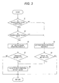
- Fig. 3 illustrates a flowchart of an operation flow of the shift control apparatus according to the first embodiment of the present invention.
- the shift control apparatus includes a controller 11 in which an operating amount of the brake pedal required for validating the shift operation of the shift lever I from the P position to the N position is set.
- the controller 11 includes a shift position determining unit 12 that determines the shift position of the shift lever 1.
- the controller 11 includes a first brake operating amount setting unit 13.
- the first brake operating amount setting unit 13 sets a first brake operating amount which is referred to when the charging state detecting unit detects that the power supply plug is not connected. That is, the operating amount of the brake pedal for validating the shift operation of the shift lever 1 from the P position to the N position is set as the first brake operating amount (first changing condition amount).
- the controller 11 includes a second brake operating amount setting unit 14.
- the second brake operating amount setting unit 14 sets a second brake operating amount which is referred to when the charging state detecting unit detects that the power supply plug is connected.
- the second brake operating amount (second changing condition amount) is set to be larger than the first brake operating amount.
- the controller 11 includes a brake operating amount determining unit 15 that selects and determines a brake operating amount for validating the shift operation of the shift lever 1 based on input information. That is, the brake operating amount determining unit 15 selects one of the first brake operating amount set by the first brake operating amount setting unit 13 and the second brake operating amount set by the second brake operating amount setting unit 14 based on input information. The brake operating amount determining unit 15 determines whether an actual brake operating amount reaches the selected operating amount.
- Operation information of the shift lever 1, connection information of the power supply plug, operating amount information of the brake pedal (brake operating amount information), and operation information of a parking brake as the traveling limiting unit are input to the controller 11.
- the controller 11 outputs an operation command to an actuator that performs the shift operation to validate the shift operation of the shift lever 1.
- step S1 it is determined in step S1 whether the power supply plug is connected.
- step S2 it is determined in step S2 whether the parking brake is turned off (deactivated).
- step S3 first brake operating amount setting unit 13
- step S2 When it is determined in step S2 that the parking brake is not turned off, that is, when it is determined that the parking brake is turned on and the parking brake is activated, the first brake operating amount B is set in step S3 (second brake operating amount setting unit 14) without depending on whether the power supply plug is connected.
- step S4 After the first brake operating amount B is set in step S3, it is determined in step S4 whether the operating amount of the brake pedal is equal to or larger than the first brake operating amount B. When it is determined in step S4 that the operating amount of the brake pedal is equal to or larger than the first brake operating amount B, the shift operation of the shift lever 1 is validated in step S5.
- the shift operation of the shift lever 1 can be validated.
- the shift operation of the shift lever 1 can be validated.
- step S2 when it is determined in step S2 that the parking brake is turned off, the parking brake is deactivated in a state in which the power supply plug is connected. Accordingly, in step S6, a second brake operating amount A which is larger than the first brake operating amount B is set.
- step S7 After the second brake operating amount A is set in step S6, it is determined in step S7 whether the operating amount of the brake pedal is equal to or larger than the second brake operating amount A. When it is determined in step S7 that the operating amount of the brake pedal is equal to or larger than the second brake operating amount A, the shift operation of the shift lever 1 is validated in step S5.
- the shift operation of the shift lever 1 can be validated.
- the second brake operating amount A may be set to a level at which it is detected that the brake pedal is stepped on more than normal.
- the operating condition of the parking brake that limits traveling of the vehicle is referred to. Accordingly, it is possible to change the condition for validating the shift operation of the shift lever 1 in correlation with the operation of the parking brake.
- the traveling limiting unit that limits traveling of the vehicle refers to the operating condition of the parking brake, but the process (step S2) of determining whether the parking brake is turned off may be skipped.
- any one of a sensor that detects an open/closed state of a door, a sensor that detects a wearing state of a seat belt, a sensor that detects an inclination of a sideview mirror, and a sitting sensor that detects sitting of an occupant or a combination thereof can be used.
- a sensor that detects an open/closed state of a door a sensor that detects a wearing state of a seat belt
- a sensor that detects an inclination of a sideview mirror a sitting sensor that detects sitting of an occupant or a combination thereof
- a sitting sensor that detects sitting of an occupant or a combination thereof
- the above-mentioned shift control apparatus can validate the shift operation of the shift lever 1, when the power supply plug is connected but the operating amount of the brake pedal is larger than the second brake operating amount A, that is, when the predetermined condition is satisfied.
- FIG. 4 illustrates a block configuration of the shift control apparatus according to the second embodiment of the present invention
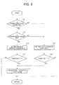
- Fig. 5 illustrates a flowchart of an operation flow of the shift control apparatus according to the second embodiment of the present invention.
- the same elements as those in the first embodiment illustrated in Fig. 3 are referenced by the same reference signs.
- the shift control apparatus validates the shift operation of the shift lever 1 of shifting the shift lever 1 from the reference position X (P position) to the N position which is a predetermined operation position when the charging state is detected and the predetermined condition is satisfied.
- a shift operation duration of the shift lever 1 (the operating amount of the limiting member) is used as the predetermined condition.
- the shift control apparatus includes a controller 21 in which a shift operation duration of the shift lever 1 required for validating the shift operation of the shift lever 1 from the P position to the N position is set.
- the controller 21 includes a shift position determining unit 12 that determines the shift position of the shift lever 1.
- the controller 21 includes a first shift operation duration setting unit 23.
- the first shift operation duration setting unit 23 sets a first shift operation duration of the shift lever 1 which is referred to when the charging state detecting unit detects that the power supply plug is not connected. That is, the shift operation duration of the shift lever 1 to one side of the N position for validating the shift operation of the shift lever 1 from the P position to the N position is set as the first shift operation duration (first changing condition amount).
- the controller 21 includes a second shift operation duration setting unit 24.
- the second shift operation duration setting unit 24 sets a second shift operation duration of the shift lever 1 which is referred to when the charging state detecting unit detects that the power supply plug is not connected.
- the second shift operation duration (second changing condition amount) is set to be longer than the first shift operation duration.
- the controller 21 includes a duration determining unit 25 that selects and determines the shift operation duration for validating the shift operation of the shift lever 1 based on input information. That is, the duration determining unit 25 selects one of the first shift operation duration set by the first shift operation duration setting unit 23 and the second shift operation duration set by the second shift operation duration setting unit 24 based on input information. The duration determining unit 25 determines whether an actual shift operation duration of the shift lever 1 reaches the selected duration.
- Operation information of the shift lever 1, connection information of the power supply plug, and operation information of a parking brake as the traveling limiting unit are input to the controller 21.
- the controller 21 outputs an operation command to an actuator that performs the shift operation to validate the shift operation of the shift lever 1.
- step S11 it is determined in step S11 whether the power supply plug is connected.
- step S12 it is determined in step S12 whether the parking brake is turned off (deactivated).
- step S11 the power supply plug is not connected, that is, when the charging state is not detected, the first shift operation duration T1 is set in step S13 (first shift operation duration setting unit 23).
- step S12 When it is determined in step S12 that the parking brake is not turned off, that is, when it is determined that the parking brake is turned on and the parking brake is activated, the first shift operation duration T1 is set in step S13 without depending on whether the power supply plug is connected.
- step S14 After the first shift operation duration T1 is set in step S13, it is determined in step S14 whether the shift operation duration T of the shift lever 1 is equal to or longer than the first shift operation duration T1. When it is determined in step S14 that the shift operation duration T of the shift lever I is equal to or longer than the first shift operation duration T1, the shift operation of the shift lever 1 is validated in step S 15.
- the shift operation of the shift lever 1 can be validated.
- the shift operation of the shift lever 1 can be validated.
- step S12 when it is determined in step S12 that the parking brake is turned off, the parking brake is deactivated in a state in which the power supply plug is connected. Accordingly, in step S16, a second shift operation duration T2 which is longer than the first shift operation duration is set.
- step S 17 After the second shift operation duration T2 is set in step S16, it is determined in step S 17 whether the shift operation duration T of the shift lever 1 is equal to or longer than the second shift operation duration T2. When it is determined in step S17 that the shift operation duration T of the shift lever 1 is equal to or longer than the second shift operation duration T2, the shift operation of the shift lever 1 is validated in step S15.
- the shift operation of the shift lever 1 can be validated.
- the second shift operation duration T2 may be set to a time in which it is detected that the shift lever 1 is held at the N position longer than normal.
- the operating condition of the parking brake that limits traveling of the vehicle is referred to. Accordingly, it is possible to change the condition for validating the shift operation of the shift lever 1 in correlation with the operation of the parking brake.
- the shift operation duration of the shift lever 1 is used as the operating amount of the limiting member, but the first shift operation duration and the second shift operation duration may be replaced with a first shift operating amount and a second shift operating amount. That is, when the power supply plug is not connected, it may be possible to determine that the shift lever 1 is shifted from the P position to the N position based on the first shift operating amount and to validate the shift operation. When the power supply plug is connected, it may be possible to determine that the shift lever 1 is shifted from the P position to the N position based on the second shift operating amount which is larger than the first shift operating amount and to validate the shift operation.
- the shift operating amount can be easily determined by detecting a value of a voltage of a positional sensor which detects a position of the shift lever 1.
- the traveling limiting unit that limits traveling of the vehicle refers to the operating condition of the parking brake, but the process (step S12) of determining whether the parking brake is turned off may be skipped similarly to the first embodiment.
- any one of a sensor that detects an open/closed state of a door, a sensor that detects a wearing state of a seat belt, a sensor that detects an inclination of a sideview mirror, and a sitting sensor that detects sitting of an occupant or a combination thereof can be used.
- a sensor that detects an open/closed state of a door a sensor that detects a wearing state of a seat belt
- a sensor that detects an inclination of a sideview mirror a sitting sensor that detects sitting of an occupant or a combination thereof
- a sitting sensor that detects sitting of an occupant or a combination thereof
- the above-mentioned shift control apparatus can validate the shift operation of the shift lever 1, when the power supply plug is connected but the shift operation duration of the shift lever 1 is longer than the second shift operation duration T2, that is, when the predetermined condition is satisfied.
- the present invention can be used in the industrial field of a shift control apparatus of a vehicle which is charged with external power.
Landscapes
- Engineering & Computer Science (AREA)
- General Engineering & Computer Science (AREA)
- Mechanical Engineering (AREA)
- Power Engineering (AREA)
- Transportation (AREA)
- Electric Propulsion And Braking For Vehicles (AREA)
- Control Of Transmission Device (AREA)
- Arrangement Or Mounting Of Control Devices For Change-Speed Gearing (AREA)
- Hybrid Electric Vehicles (AREA)
Abstract
Description
- The present invention relates to a shift control apparatus of a vehicle which is charged with external power.
- In recent years, with interests in environmental issues, various electric vehicles have been spread and various vehicles which are charged with external power are known. As the vehicles which are charged with external power, for example, a vehicle that acquires a traveling driving force from a driving force of an electric motor and a vehicle that acquires a traveling driving force by combining a driving force of an engine and a driving force of an electric motor are known.
- In a vehicle which is charged with external power, for example, a power supply plug extending from external power supply equipment (charging equipment) or an external power supply is inserted into a charging port and the vehicle is supplied and charged with power. When the vehicle travels in a state in which the power supply plug is inserted into the charging port, there is a possibility that the power supply plug or the charging port will be destroyed. As a technique of preventing destruction of the power supply plug or the charging port, a technique of invalidating an operation of a shift lever in a state in which the power supply plug is inserted into the charging port is known in the related art (for example, see Japanese Patent No.
5580132 - In the technique disclosed in Japanese Patent No.
5580132 - However, even in a state in which the power supply plug is inserted into the charging port during supply of power (even under charging), it may be necessary to take in and out a piece of baggage or for an occupant to go in and out a vehicle interior. Depending on a position of the vehicle under charging, taking in and out of a piece of baggage or going in and out of an occupant may be impossible. In this case, by moving the vehicle within an allowable length range of a power supply cord, taking in and out of a piece of baggage or going in and out of an occupant becomes possible. Even when the power supply plug is not actually inserted into the charging port, it may be determined that the vehicle is under charging and an operation of the shift lever may be invalidated due to erroneous determination of a charging state. In this case, when the operation of the shift lever can be validated and the shift lever can be shifted to a neutral state by a shift operation of the shift lever, movement by a wrecker or the like can be facilitated.
- In the technique disclosed in Japanese Patent No.
5580132 - The present invention is made in consideration of the above-mentioned circumstances and an object thereof is to provide a shift control apparatus that can validate a shift operation of a shift lever when a charging state is detected but a predetermined condition is satisfied.
- According to an aspect of the invention, when the charging state of the vehicle is detected by the charging state detecting unit and the operating amount of the limiting member is equal to or larger than the second changing condition amount which is an operating amount larger than the first changing operating amount, the shift operation of the shift lever from the reference position to the predetermined operation position is validated. Accordingly, when the charging state is detected but the operating amount of the limiting member increases, the shift operation of the shift lever from the reference position to the predetermined position is validated. As a result, it is possible to validate the shift operation of the shift lever when a disconnected state is detected but a predetermined limiting condition is satisfied. The shift lever which is held at the predetermined reference position employs, for example, a shift lever which is biased to the predetermined reference position.
- In detecting the charging state, the charging state of the vehicle is detected by inserting the power supply plug into the charging port to transition to a state in which charging can be carried out. For example, when a noncontact charger is used, the charging state is detected by locating the vehicle in a predetermined chargeable range.
- According to another aspect of the invention, when the charging state of the vehicle is detected by the charging state detecting unit and the operating amount of the brake pedal is larger than the second brake operating amount larger than the first brake operating amount, the shift operation of the shift lever from the reference position to the predetermined position is validated. Accordingly, when the charging state is detected but the operating amount of the brake pedal increases, the shift operation of the shift lever from the reference position to the predetermined position is validated. As a result, when the charging state is detected but the operating amount of the brake pedal increases, it is possible to determine that a predetermined limiting condition is satisfied and to validate the shift operation of the shift lever.
- According to another aspect of the invention, when the charging state of the vehicle is detected by the charging state detecting unit and the shift operation duration of the shift lever is the second shift operation duration longer than the first shift operation duration, it is determined that the shift lever is shifted to the operation position and the shift operation is validated. Accordingly, when the charging state is detected but the shift operation duration of the shift lever increases, the shift operation of the shift lever is validated. As a result, when the charging state is detected but the shift operation duration of the shift lever increases, it is possible to determine that a predetermined limiting condition is satisfied and to validate the shift operation of the shift lever.
- According to another aspect of the invention, when the charging state of the vehicle is detected by the charging state detecting unit and the shift operating amount of the shift lever is the second shift operating amount larger than the first shift operating amount, it is determined that the shift lever is shifted to the operation position and the shift operation is validated. Accordingly, when the charging state is detected but the shift operating amount of the shift lever increases, the shift operation of the shift lever is validated. As a result, when the charging state is detected but the shift operating amount of the shift lever increases, it is possible to determine that a predetermined limiting condition is satisfied and to validate the shift operation of the shift lever.
- According to another aspect of the invention, since the operating condition of the traveling limiting unit that limits traveling of the vehicle is used to validate the shift operation of the shift lever based on the second changing condition amount, the operation of validating the shift operation of the shift lever can be intentionally performed in correlation with the operation of the traveling limiting unit.
- According to another aspect of the invention, when the parking brake is deactivated, the shift operation of the shift lever is validated based on the second changing condition amount. Accordingly, the operation of validating the shift operation of the shift lever can be intentionally performed under the condition in which the parking brake is deactivated and traveling is possible.
- As the traveling limiting unit, a sensor that detects an open/closed state of a door, a sensor that detects a wearing state of a seat belt, a sensor that detects an inclination of a sideview mirror, and a sitting sensor that detects sitting of an occupant can be used. In this case, when it is intended to validate the shift operation of the shift lever based on the second changing condition amount, the open state of the door, the non-wearing state of the seat belt, the inclined state of the sideview mirror, and the state in which the sitting of the occupant is not detected are used, and a condition in which normal traveling is not performed can be used.
- The shift control apparatus according to the present invention can validate a shift operation of a shift lever when a charging state is detected but a predetermined condition is satisfied.
-
-
Fig. 1 is a diagram illustrating an appearance of a shift lever according to the present invention. -
Fig. 2 is a block diagram illustrating a configuration of a shift control apparatus according to a first embodiment of the present invention. -
Fig. 3 is a flowchart illustrating an operation flow of the shift control apparatus according to the first embodiment of the present invention. -
Fig. 4 is a block diagram illustrating a configuration of a shift control apparatus according to a second embodiment of the present invention. -
Fig. 5 is a flowchart illustrating an operation flow of the shift control apparatus according to the second embodiment of the present invention. - A shift control apparatus according to the present invention is a shift control apparatus of a vehicle which is supplied and charged with power from the outside and validates a shift operation of a shift lever from a reference position to a predetermined operation position when a predetermined condition is satisfied under a predetermined limitation by a limiting member even under charging or in a state in which charging can be carried out (when a charging state is detected). For example, a shift operation from a P position which is a position of a parking state to an N position which is a neutral position is validated.
- As the predetermined condition, any one of an operating amount of a brake pedal, a duration of a shift operation of the shift lever, and an operating amount of the shift operation of the shift lever or a combination thereof, which are carried out to enable the shift operation of the shift lever, can be used. The shift operation of the shift lever is validated, for example, when a brake pedal is stepped more than normal. For example, the shift operation of the shift lever may be validated when the shift lever is operated for a period of time longer than normal or by an operating amount larger than normal.
- By validating the shift operation of the shift lever under a predetermined limitation by a limiting member, a vehicle can move even under charging or in a state in which charging can be carried out. Accordingly, a vehicle under charging or in a state in which charging can be carried out can be moved slightly to enable taking in and out of a piece of baggage or an occupant's going in and out, thereby improving usability.
- A shift lever which is applied to the shift control apparatus according to the present invention will be described below with reference to
Fig. 1. Fig. 1 illustrates an appearance of the shift lever which is applied to the shift control apparatus according to the present invention. - The
shift lever 1 in a state illustrated by broken lines in the drawing is operated in the direction indicated by a dotted arrow inFig. 1 , theshift lever 1 is shifted from a reference position X (a solid line inFig. 1 ) to a neutral position (N position), a drive position (D position), or a reverse position (R position), the shift operation is validated when the operation time reaches a predetermined duration, and the shift position is switched by an actuator. By detaching a hand from theshift lever 1 after the shift operation is validated, theshift lever 1 moves back in the direction indicated by a solid arrow inFig. 1 and is returned to the reference position X. By pushing a parking button P when theshift lever 1 is positioned at the reference position X, the reference position X is set to the position of a parking state (P position). - As the drive mechanism of the shift lever, a mechanism of shifting the shift lever to the P position, the R position, the N position, and the D position and holding the shift lever at that position may be employed.
- A vehicle having the
shift lever 1 illustrated inFig. 1 includes a shift control apparatus according to an embodiment of the present invention. The vehicle having the shift control apparatus according to an embodiment of the present invention is a vehicle which is supplied and charged with external power and includes a power supply port which is connected to a power supply plug. When the power supply plug is connected to the power supply port, a charging state of the vehicle is detected (charging state detecting unit). - The charging state detecting unit may detect the charging state of the vehicle when the power supply plug is connected and the supply of power is actually started. In case of a noncontact charger, when the vehicle moves to a predetermined chargeable range or the charging is actually started, the charging state detecting unit may detect the charging state of the vehicle.
- In a shift control apparatus according to a first embodiment of the present invention, when the charging state is detected and a predetermined condition is satisfied, a shift operation of the
shift lever 1 of shifting theshift lever 1 from a reference position X (P position) to the N position as a predetermined operation position is validated. As the predetermined condition, an operating amount of a brake pedal (an operating amount of the limiting member) which is performed to enable the shift operation of the shift lever is applied. - The shift control apparatus according to the first embodiment of the present invention will be specifically described below with reference to
Figs. 2 and3 .Fig. 2 illustrates a block configuration of the shift control apparatus according to the first embodiment of the present invention andFig. 3 illustrates a flowchart of an operation flow of the shift control apparatus according to the first embodiment of the present invention. - The block configuration of the shift control apparatus will be specifically described with reference to
Fig. 2 . - As illustrated in the drawing, the shift control apparatus includes a
controller 11 in which an operating amount of the brake pedal required for validating the shift operation of the shift lever I from the P position to the N position is set. Thecontroller 11 includes a shiftposition determining unit 12 that determines the shift position of theshift lever 1. - The
controller 11 includes a first brake operatingamount setting unit 13. The first brake operatingamount setting unit 13 sets a first brake operating amount which is referred to when the charging state detecting unit detects that the power supply plug is not connected. That is, the operating amount of the brake pedal for validating the shift operation of theshift lever 1 from the P position to the N position is set as the first brake operating amount (first changing condition amount). - The
controller 11 includes a second brake operatingamount setting unit 14. The second brake operatingamount setting unit 14 sets a second brake operating amount which is referred to when the charging state detecting unit detects that the power supply plug is connected. As the operating amount of the brake pedal for validating the shift operation of theshift lever 1 from the P position to the N position, the second brake operating amount (second changing condition amount) is set to be larger than the first brake operating amount. - The
controller 11 includes a brake operatingamount determining unit 15 that selects and determines a brake operating amount for validating the shift operation of theshift lever 1 based on input information. That is, the brake operatingamount determining unit 15 selects one of the first brake operating amount set by the first brake operatingamount setting unit 13 and the second brake operating amount set by the second brake operatingamount setting unit 14 based on input information. The brake operatingamount determining unit 15 determines whether an actual brake operating amount reaches the selected operating amount. - Operation information of the
shift lever 1, connection information of the power supply plug, operating amount information of the brake pedal (brake operating amount information), and operation information of a parking brake as the traveling limiting unit are input to thecontroller 11. Thecontroller 11 outputs an operation command to an actuator that performs the shift operation to validate the shift operation of theshift lever 1. - The control operation will be specifically described below with reference to
Fig. 3 . - As illustrated in the drawing, it is determined in step S1 whether the power supply plug is connected. When it is determined in step S1 that the power supply plug is connected, it is determined in step S2 whether the parking brake is turned off (deactivated). When it is determined in step S1 that the power supply plug is not connected, that is, when the charging state is not detected, the first brake operating amount B is set in step S3 (first brake operating amount setting unit 13).
- When it is determined in step S2 that the parking brake is not turned off, that is, when it is determined that the parking brake is turned on and the parking brake is activated, the first brake operating amount B is set in step S3 (second brake operating amount setting unit 14) without depending on whether the power supply plug is connected.
- After the first brake operating amount B is set in step S3, it is determined in step S4 whether the operating amount of the brake pedal is equal to or larger than the first brake operating amount B. When it is determined in step S4 that the operating amount of the brake pedal is equal to or larger than the first brake operating amount B, the shift operation of the
shift lever 1 is validated in step S5. - When the power supply plug is not connected and the operating amount of the brake pedal is equal to or larger than the first brake operating amount B, the shift operation of the
shift lever 1 can be validated. When the power supply plug is connected but the parking brake is activated and the operating amount of the brake pedal is equal to or larger than the first brake operating amount B, the shift operation of theshift lever 1 can be validated. - On the other hand, when it is determined in step S2 that the parking brake is turned off, the parking brake is deactivated in a state in which the power supply plug is connected. Accordingly, in step S6, a second brake operating amount A which is larger than the first brake operating amount B is set.
- After the second brake operating amount A is set in step S6, it is determined in step S7 whether the operating amount of the brake pedal is equal to or larger than the second brake operating amount A. When it is determined in step S7 that the operating amount of the brake pedal is equal to or larger than the second brake operating amount A, the shift operation of the
shift lever 1 is validated in step S5. - That is, when the power supply plug is connected in a state in which the parking brake is deactivated and a predetermined condition that the operating amount of the brake pedal is equal to or larger than the second brake operating amount A which is larger than the first brake operating amount B is satisfied, the shift operation of the
shift lever 1 can be validated. - When the power supply plug is connected and the operating amount of the brake pedal reaches the second brake operating amount A which is larger than the first brake operating amount B, the shift operation of the
shift lever 1 from the P position to the N position is validated. That is, when the power supply plug is connected but the operating amount of the brake pedal increases, the shift operation of theshift lever 1 is validated. The second brake operating amount A may be set to a level at which it is detected that the brake pedal is stepped on more than normal. - When the power supply plug is connected but the operating amount of the brake pedal increases, it is possible to determine that the predetermined condition is satisfied and to validate the shift operation of the
shift lever 1, thereby moving the vehicle. Accordingly, it is possible to move slightly even a vehicle under charging and to enable taking in and out of a piece of baggage and an occupant's going in and out, thereby improving usability. - When the shift operation of the
shift lever 1 is validated based on the second brake operating amount A, the operating condition of the parking brake that limits traveling of the vehicle is referred to. Accordingly, it is possible to change the condition for validating the shift operation of theshift lever 1 in correlation with the operation of the parking brake. - The traveling limiting unit that limits traveling of the vehicle refers to the operating condition of the parking brake, but the process (step S2) of determining whether the parking brake is turned off may be skipped.
- As the traveling limiting unit, any one of a sensor that detects an open/closed state of a door, a sensor that detects a wearing state of a seat belt, a sensor that detects an inclination of a sideview mirror, and a sitting sensor that detects sitting of an occupant or a combination thereof can be used. For example, when the open state of the door, the non-wearing state of the seat belt, the inclined state of the sideview mirror, or the state in which the sitting of the occupant is not detected is detected, it may be determined whether to validate the shift operation of the
shift lever 1 by comparing the brake operating amount with the second brake operating amount A. - The above-mentioned shift control apparatus can validate the shift operation of the
shift lever 1, when the power supply plug is connected but the operating amount of the brake pedal is larger than the second brake operating amount A, that is, when the predetermined condition is satisfied. - A shift control apparatus according to a second embodiment of the present invention will be specifically described below with reference to
Figs. 4 and5 .Fig. 4 illustrates a block configuration of the shift control apparatus according to the second embodiment of the present invention andFig. 5 illustrates a flowchart of an operation flow of the shift control apparatus according to the second embodiment of the present invention. The same elements as those in the first embodiment illustrated inFig. 3 are referenced by the same reference signs. - Similarly to the first embodiment, the shift control apparatus according to the second embodiment of the present invention validates the shift operation of the
shift lever 1 of shifting theshift lever 1 from the reference position X (P position) to the N position which is a predetermined operation position when the charging state is detected and the predetermined condition is satisfied. A shift operation duration of the shift lever 1 (the operating amount of the limiting member) is used as the predetermined condition. - The block configuration of the shift control apparatus will be specifically described with reference to
Fig. 4 . - As illustrated in the drawing, the shift control apparatus includes a
controller 21 in which a shift operation duration of theshift lever 1 required for validating the shift operation of theshift lever 1 from the P position to the N position is set. Thecontroller 21 includes a shiftposition determining unit 12 that determines the shift position of theshift lever 1. - The
controller 21 includes a first shift operationduration setting unit 23. The first shift operationduration setting unit 23 sets a first shift operation duration of theshift lever 1 which is referred to when the charging state detecting unit detects that the power supply plug is not connected. That is, the shift operation duration of theshift lever 1 to one side of the N position for validating the shift operation of theshift lever 1 from the P position to the N position is set as the first shift operation duration (first changing condition amount). - The
controller 21 includes a second shift operationduration setting unit 24. The second shift operationduration setting unit 24 sets a second shift operation duration of theshift lever 1 which is referred to when the charging state detecting unit detects that the power supply plug is not connected. As the shift operation duration of theshift lever 1 to one side of the N position for validating the shift operation of theshift lever 1 from the P position to the N position, the second shift operation duration (second changing condition amount) is set to be longer than the first shift operation duration. - The
controller 21 includes aduration determining unit 25 that selects and determines the shift operation duration for validating the shift operation of theshift lever 1 based on input information. That is, theduration determining unit 25 selects one of the first shift operation duration set by the first shift operationduration setting unit 23 and the second shift operation duration set by the second shift operationduration setting unit 24 based on input information. Theduration determining unit 25 determines whether an actual shift operation duration of theshift lever 1 reaches the selected duration. - Operation information of the
shift lever 1, connection information of the power supply plug, and operation information of a parking brake as the traveling limiting unit are input to thecontroller 21. Thecontroller 21 outputs an operation command to an actuator that performs the shift operation to validate the shift operation of theshift lever 1. - The control operation will be specifically described below with reference to
Fig. 5 . - As illustrated in the drawing, it is determined in step S11 whether the power supply plug is connected. When it is determined in step S11 that the power supply plug is connected, it is determined in step S12 whether the parking brake is turned off (deactivated). When it is determined in step S11 that the power supply plug is not connected, that is, when the charging state is not detected, the first shift operation duration T1 is set in step S13 (first shift operation duration setting unit 23).
- When it is determined in step S12 that the parking brake is not turned off, that is, when it is determined that the parking brake is turned on and the parking brake is activated, the first shift operation duration T1 is set in step S13 without depending on whether the power supply plug is connected.
- After the first shift operation duration T1 is set in step S13, it is determined in step S14 whether the shift operation duration T of the
shift lever 1 is equal to or longer than the first shift operation duration T1. When it is determined in step S14 that the shift operation duration T of the shift lever I is equal to or longer than the first shift operation duration T1, the shift operation of theshift lever 1 is validated instep S 15. - When the power supply plug is not connected and the shift operation duration of the shift lever I is equal to or longer than the first shift operation duration T1, the shift operation of the
shift lever 1 can be validated. When the power supply plug is connected but the parking brake is activated and the shift operation duration of theshift lever 1 is equal to or longer than the first shift operation duration T1, the shift operation of theshift lever 1 can be validated. - On the other hand, when it is determined in step S12 that the parking brake is turned off, the parking brake is deactivated in a state in which the power supply plug is connected. Accordingly, in step S16, a second shift operation duration T2 which is longer than the first shift operation duration is set.
- After the second shift operation duration T2 is set in step S16, it is determined in step S 17 whether the shift operation duration T of the
shift lever 1 is equal to or longer than the second shift operation duration T2. When it is determined in step S17 that the shift operation duration T of theshift lever 1 is equal to or longer than the second shift operation duration T2, the shift operation of theshift lever 1 is validated in step S15. - That is, when the power supply plug is connected in a state in which the parking brake is deactivated and a predetermined condition that the shift operation duration of the
shift lever 1 is equal to or longer than the second shift operation duration T2 which is longer than the first shift operation duration T1 is satisfied, the shift operation of theshift lever 1 can be validated. - When the power supply plug is connected and the shift operation duration T of the
shift lever 1 reaches the second shift operation duration T2 which is longer than the first shift operation duration T1, the shift operation of theshift lever 1 from the P position to the N position is validated. When the power supply plug is connected but the shift operation of theshift lever 1 continues to be performed long, the shift operation of theshift lever 1 is validated. The second shift operation duration T2 may be set to a time in which it is detected that theshift lever 1 is held at the N position longer than normal. - When the power supply plug is connected but the shift operation of the
shift lever 1 continues to be performed long, it is possible to determine that the predetermined condition is satisfied and to validate the shift operation of theshift lever 1, thereby moving the vehicle. Accordingly, it is possible to move slightly even a vehicle under charging and to enable taking in and out of a piece of baggage and an occupant's going in and out, thereby improving usability. - When the shift operation of the
shift lever 1 is validated based on the second shift operation duration T2, the operating condition of the parking brake that limits traveling of the vehicle is referred to. Accordingly, it is possible to change the condition for validating the shift operation of theshift lever 1 in correlation with the operation of the parking brake. - In the second embodiment, the shift operation duration of the
shift lever 1 is used as the operating amount of the limiting member, but the first shift operation duration and the second shift operation duration may be replaced with a first shift operating amount and a second shift operating amount. That is, when the power supply plug is not connected, it may be possible to determine that theshift lever 1 is shifted from the P position to the N position based on the first shift operating amount and to validate the shift operation. When the power supply plug is connected, it may be possible to determine that theshift lever 1 is shifted from the P position to the N position based on the second shift operating amount which is larger than the first shift operating amount and to validate the shift operation. For example, the shift operating amount can be easily determined by detecting a value of a voltage of a positional sensor which detects a position of theshift lever 1. - The traveling limiting unit that limits traveling of the vehicle refers to the operating condition of the parking brake, but the process (step S12) of determining whether the parking brake is turned off may be skipped similarly to the first embodiment.
- Similarly to the first embodiment, as the traveling limiting unit, any one of a sensor that detects an open/closed state of a door, a sensor that detects a wearing state of a seat belt, a sensor that detects an inclination of a sideview mirror, and a sitting sensor that detects sitting of an occupant or a combination thereof can be used. For example, when the open state of the door, the non-wearing state of the seat belt, the inclined state of the sideview mirror, or the state in which the sitting of the occupant is not detected is detected, it may be determined whether to validate the shift operation of the
shift lever 1 by comparing the shift operation duration of theshift lever 1 with the second shift operation duration T2. - The above-mentioned shift control apparatus can validate the shift operation of the
shift lever 1, when the power supply plug is connected but the shift operation duration of theshift lever 1 is longer than the second shift operation duration T2, that is, when the predetermined condition is satisfied. - The present invention can be used in the industrial field of a shift control apparatus of a vehicle which is charged with external power.
Claims (10)
- A shift control apparatus of a vehicle which is supplied and charged with external power, the shift control apparatus comprising:a charging state detecting unit that detects a charging state of the vehicle;a shift lever that is held at a predetermined reference position;a limiting member that validates an operation of the shift lever located at the reference position when the limiting member is operated; anda controller that validates a shift operation of the shift lever from the reference position to a predetermined operation position when the charging state of the vehicle is not detected by the charging state detecting unit and an operating amount of the limiting member is equal to or larger than a first changing condition amount and validates the shift operation of the shift lever from the reference position to the predetermined operation position when the charging state of the vehicle is detected by the charging state detecting unit and the operating amount of the limiting member is equal to or larger than a second changing condition amount which is an operating amount larger than the first changing condition amount.
- The shift control apparatus according to claim 1, wherein the limiting member is a brake pedal and the operating amount of the limiting member is an operating amount of the brake pedal,
the shift operation of the shift lever from the reference position to the predetermined operation position is validated when the charging state of the vehicle is not detected by the charging state detecting unit and the operating amount of the brake pedal is larger than a first brake operating amount corresponding to the first changing condition amount, and
the shift operation of the shift lever from the reference position to the predetermined operation position when the charging state of the vehicle is detected by the charging state detecting unit and the operating amount of the brake pedal is larger than a second brake operating amount corresponding to the second changing condition amount which is larger than the first brake operating amount. - The shift control apparatus according to claim 1, wherein the limiting member is a shift lever and the operating amount of the limiting member is a shift operation duration of the shift lever,
the shift operation of the shift lever to the predetermined operation position is validated when the charging state of the vehicle is not detected by the charging state detecting unit and the shift operation duration of the shift lever is greater than a first shift operation duration corresponding to the first changing condition amount, and
the shift operation of the shift lever to the predetermined operation position is validated when the charging state of the vehicle is detected by the charging state detecting unit and the shift operation duration of the shift lever is greater than a second shift operation duration corresponding to the second changing condition amount which is greater than the first shift operation duration. - The shift control apparatus according to claim 1, wherein the limiting member is a shift lever and the operating amount of the limiting member is a shift operating amount of the shift lever,
the shift operation of the shift lever to the predetermined operation position is validated when the charging state of the vehicle is not detected by the charging state detecting unit and the shift operation duration of the shift lever is greater than a first shift operating amount corresponding to the first changing condition amount, and
the shift operation of the shift lever to the predetermined operation position is validated when the charging state of the vehicle is detected by the charging state detecting unit and the shift operation duration of the shift lever is greater than a second shift operating amount corresponding to the second changing condition amount which is an operating amount larger than the first shift operating amount. - The shift control apparatus according to any one of claims 1 to 4, wherein an operating condition of a traveling limiting unit that limits traveling of the vehicle is used to validate the shift operation of the shift lever from the reference position to the predetermined operation position based on the second changing condition amount.
- The shift control apparatus according to claim 5, wherein the traveling limiting unit is a parking brake, and
the shift operation of the shift lever from the reference position to the predetermined operation position is validated based on the second changing condition amount when the parking brake is deactivated. - The shift control apparatus according to claim 5, wherein the traveling limiting unit is a sensor that detects an open/closed state of a door, and
the shift operation of the shift lever from the reference position to the predetermined operation position is validated based on the second changing condition amount when the open state of the door is detected by the sensor. - The shift control apparatus according to claim 5, wherein the traveling limiting unit is a sensor that detects a wearing state of a seat belt, and
the shift operation of the shift lever from the reference position to the predetermined operation position is validated based on the second changing condition amount when the wearing state of the seat belt is not detected by the sensor. - The shift control apparatus according to claim 5, wherein the traveling limiting unit is a sensor that detects a received state of a sideview mirror, and
the shift operation of the shift lever from the reference position to the predetermined operation position is validated based on the second changing condition amount when the received state of the sideview mirror is detected by the sensor. - The shift control apparatus according to claim 5, wherein the traveling limiting unit is a sensor that detects a sitting state of an occupant, and
the shift operation of the shift lever from the reference position to the predetermined operation position is validated based on the second changing condition amount when the sitting state of the occupant is not detected by the sensor.
Priority Applications (1)
| Application Number | Priority Date | Filing Date | Title |
|---|---|---|---|
| EP20151181.3A EP3657048B1 (en) | 2015-04-24 | 2016-04-20 | Shift control apparatus |
Applications Claiming Priority (1)
| Application Number | Priority Date | Filing Date | Title |
|---|---|---|---|
| JP2015089749A JP6525146B2 (en) | 2015-04-24 | 2015-04-24 | Shift control device |
Related Child Applications (2)
| Application Number | Title | Priority Date | Filing Date |
|---|---|---|---|
| EP20151181.3A Division EP3657048B1 (en) | 2015-04-24 | 2016-04-20 | Shift control apparatus |
| EP20151181.3A Division-Into EP3657048B1 (en) | 2015-04-24 | 2016-04-20 | Shift control apparatus |
Publications (3)
| Publication Number | Publication Date |
|---|---|
| EP3085999A2 true EP3085999A2 (en) | 2016-10-26 |
| EP3085999A3 EP3085999A3 (en) | 2016-11-16 |
| EP3085999B1 EP3085999B1 (en) | 2025-06-11 |
Family
ID=56087072
Family Applications (2)
| Application Number | Title | Priority Date | Filing Date |
|---|---|---|---|
| EP16166169.9A Active EP3085999B1 (en) | 2015-04-24 | 2016-04-20 | Shift control apparatus |
| EP20151181.3A Active EP3657048B1 (en) | 2015-04-24 | 2016-04-20 | Shift control apparatus |
Family Applications After (1)
| Application Number | Title | Priority Date | Filing Date |
|---|---|---|---|
| EP20151181.3A Active EP3657048B1 (en) | 2015-04-24 | 2016-04-20 | Shift control apparatus |
Country Status (3)
| Country | Link |
|---|---|
| US (1) | US9765879B2 (en) |
| EP (2) | EP3085999B1 (en) |
| JP (1) | JP6525146B2 (en) |
Families Citing this family (2)
| Publication number | Priority date | Publication date | Assignee | Title |
|---|---|---|---|---|
| JP6786619B2 (en) | 2016-10-17 | 2020-11-18 | 三井化学株式会社 | Dental connecting members, mouthpieces and orthodontic appliances |
| WO2018110484A1 (en) * | 2016-12-14 | 2018-06-21 | パナソニックIpマネジメント株式会社 | Position detection device |
Citations (1)
| Publication number | Priority date | Publication date | Assignee | Title |
|---|---|---|---|---|
| JP5580132B2 (en) | 2010-07-28 | 2014-08-27 | 株式会社東海理化電機製作所 | Shift device |
Family Cites Families (21)
| Publication number | Priority date | Publication date | Assignee | Title |
|---|---|---|---|---|
| JP3216501B2 (en) * | 1995-10-13 | 2001-10-09 | トヨタ自動車株式会社 | Hybrid drive |
| JP2001107765A (en) * | 1999-10-08 | 2001-04-17 | Honda Motor Co Ltd | Hybrid vehicle control device |
| DE10165097B3 (en) * | 2000-07-18 | 2015-07-23 | Schaeffler Technologies AG & Co. KG | Double clutch |
| WO2005025911A1 (en) * | 2003-09-11 | 2005-03-24 | Nissan Diesel Motor Co., Ltd. | Gear shift control device of hybrid vehicle |
| JP4492585B2 (en) * | 2006-05-29 | 2010-06-30 | 日産自動車株式会社 | Hybrid vehicle control device and hybrid vehicle control method. |
| WO2010079606A1 (en) * | 2009-01-09 | 2010-07-15 | トヨタ自動車株式会社 | Control device for vehicle |
| WO2011101973A1 (en) * | 2010-02-18 | 2011-08-25 | トヨタ自動車株式会社 | Vehicle shift control device |
| JP5316705B2 (en) * | 2010-05-14 | 2013-10-16 | 日産自動車株式会社 | Control device for shift abnormality countermeasure at start-up of electric vehicle |
| CN103079869B (en) * | 2010-06-23 | 2015-06-10 | 丰田自动车株式会社 | Vehicle control device and vehicle control method |
| KR101126244B1 (en) * | 2010-06-24 | 2012-03-20 | 기아자동차주식회사 | System for warm up control of hybrid vehicle and method thereof |
| WO2012008029A1 (en) * | 2010-07-14 | 2012-01-19 | トヨタ自動車株式会社 | Vehicle shift control device |
| WO2012081124A1 (en) * | 2010-12-17 | 2012-06-21 | トヨタ自動車株式会社 | Vehicle and vehicle control method |
| WO2012117550A1 (en) * | 2011-03-03 | 2012-09-07 | トヨタ自動車株式会社 | Shift-lock apparatus for vehicle |
| JP5908675B2 (en) * | 2011-03-23 | 2016-04-26 | 株式会社デンソー | Vehicle control system |
| JP2012205314A (en) * | 2011-03-23 | 2012-10-22 | Denso Corp | Vehicle control system |
| GB201118624D0 (en) * | 2011-10-27 | 2011-12-07 | Land Rover Uk Ltd | Electric selector control system and related method |
| JP5712915B2 (en) * | 2011-12-21 | 2015-05-07 | トヨタ自動車株式会社 | Plug-in hybrid vehicle |
| US9393933B2 (en) | 2012-05-02 | 2016-07-19 | Jaguar Land Rover Limited | Vehicle security |
| GB2501728A (en) * | 2012-05-02 | 2013-11-06 | Jaguar Cars | Vehicle security during charging of an electric or hybrid vehicle |
| US9061598B2 (en) * | 2013-08-29 | 2015-06-23 | Ford Global Technologies, Llc | Method and system for providing charging cord reminder and fault override for plug-in electric vehicles |
| KR101573625B1 (en) * | 2014-08-12 | 2015-12-01 | 현대자동차주식회사 | Shift control apparatus of hybrid vehicle and method thereof |
-
2015
- 2015-04-24 JP JP2015089749A patent/JP6525146B2/en active Active
-
2016
- 2016-04-20 EP EP16166169.9A patent/EP3085999B1/en active Active
- 2016-04-20 EP EP20151181.3A patent/EP3657048B1/en active Active
- 2016-04-22 US US15/135,768 patent/US9765879B2/en active Active
Patent Citations (1)
| Publication number | Priority date | Publication date | Assignee | Title |
|---|---|---|---|---|
| JP5580132B2 (en) | 2010-07-28 | 2014-08-27 | 株式会社東海理化電機製作所 | Shift device |
Also Published As
| Publication number | Publication date |
|---|---|
| US20160312883A1 (en) | 2016-10-27 |
| JP2016203869A (en) | 2016-12-08 |
| EP3657048A1 (en) | 2020-05-27 |
| JP6525146B2 (en) | 2019-06-05 |
| EP3085999B1 (en) | 2025-06-11 |
| EP3657048B1 (en) | 2021-06-02 |
| US9765879B2 (en) | 2017-09-19 |
| EP3085999A3 (en) | 2016-11-16 |
Similar Documents
| Publication | Publication Date | Title |
|---|---|---|
| JP5452653B2 (en) | Electric vehicle and charging control method for electric vehicle | |
| US9868388B2 (en) | Apparatus and method for controlling turn signal for electronic multifunction switch | |
| US9975453B2 (en) | Apparatus for controlled power seat of vehicle and method thereof | |
| JP2018062223A5 (en) | ||
| US20160103512A1 (en) | Dual operational touch screen device for a vehicle | |
| JP6135309B2 (en) | Shift determination device | |
| KR102284693B1 (en) | Moving apparatus of vehicle seat and control method thereof | |
| KR101634881B1 (en) | Apparatus and Method for controlling seat for Vehicle | |
| US9765879B2 (en) | Shift control apparatus | |
| KR102348125B1 (en) | Apparatus and method for supporting remote parking based on posion of fob | |
| KR20160141285A (en) | Parking condition when vehicle crash prevention system | |
| KR102581825B1 (en) | Sensor arrangement for determining the position of an actuator in a vehicle and a method for operating the sensor arrangement | |
| JP2007314932A (en) | Control system for vehicle opening / closing body | |
| KR102146658B1 (en) | Device for controlling a position of seat for convenience of getting on and off of the passenger and method thereof | |
| JP6660043B2 (en) | Shift control device | |
| JP6299361B2 (en) | Ground fault detector | |
| KR20180049952A (en) | Eliminating device the blind spot of the driver's side rear-view mirror | |
| US20150362068A1 (en) | Device and Method for Driving Shift Lever | |
| EP3703243A1 (en) | Device for detecting rotation direction and method for detecting rotation direction of motor, and motor control device | |
| JP2006022513A (en) | Vehicular automatic opening/closing device | |
| JP2019070444A (en) | Shift control device | |
| KR20150082910A (en) | Steering control apparatus and steering control method for changing electric current map following friction level of reduction gear | |
| US20180105109A1 (en) | Vehicular visual recognition control device | |
| KR101732271B1 (en) | Method and system for compensating a voltage of operation in sunroof | |
| JP2005351237A (en) | Failure detection device and failure detection method for start switch of power plant |
Legal Events
| Date | Code | Title | Description |
|---|---|---|---|
| PUAI | Public reference made under article 153(3) epc to a published international application that has entered the european phase |
Free format text: ORIGINAL CODE: 0009012 |
|
| PUAL | Search report despatched |
Free format text: ORIGINAL CODE: 0009013 |
|
| 17P | Request for examination filed |
Effective date: 20160520 |
|
| AK | Designated contracting states |
Kind code of ref document: A2 Designated state(s): AL AT BE BG CH CY CZ DE DK EE ES FI FR GB GR HR HU IE IS IT LI LT LU LV MC MK MT NL NO PL PT RO RS SE SI SK SM TR |
|
| AX | Request for extension of the european patent |
Extension state: BA ME |
|
| AK | Designated contracting states |
Kind code of ref document: A3 Designated state(s): AL AT BE BG CH CY CZ DE DK EE ES FI FR GB GR HR HU IE IS IT LI LT LU LV MC MK MT NL NO PL PT RO RS SE SI SK SM TR |
|
| AX | Request for extension of the european patent |
Extension state: BA ME |
|
| RIC1 | Information provided on ipc code assigned before grant |
Ipc: F16H 59/54 20060101ALI20161012BHEP Ipc: F16H 61/22 20060101ALI20161012BHEP Ipc: F16H 61/16 20060101ALI20161012BHEP Ipc: F16H 59/50 20060101AFI20161012BHEP Ipc: F16H 61/02 20060101ALI20161012BHEP Ipc: B60L 11/18 20060101ALI20161012BHEP |
|
| RAP1 | Party data changed (applicant data changed or rights of an application transferred) |
Owner name: MITSUBISHI JIDOSHA KOGYO KABUSHIKI KAISHA |
|
| STAA | Information on the status of an ep patent application or granted ep patent |
Free format text: STATUS: EXAMINATION IS IN PROGRESS |
|
| 17Q | First examination report despatched |
Effective date: 20190919 |
|
| GRAP | Despatch of communication of intention to grant a patent |
Free format text: ORIGINAL CODE: EPIDOSNIGR1 |
|
| STAA | Information on the status of an ep patent application or granted ep patent |
Free format text: STATUS: GRANT OF PATENT IS INTENDED |
|
| RIC1 | Information provided on ipc code assigned before grant |
Ipc: B60L 53/14 20190101ALI20250203BHEP Ipc: B60L 53/00 20190101ALI20250203BHEP Ipc: F16H 61/24 20060101ALI20250203BHEP Ipc: F16H 59/10 20060101ALI20250203BHEP Ipc: F16H 61/22 20060101ALI20250203BHEP Ipc: F16H 61/16 20060101ALI20250203BHEP Ipc: F16H 61/02 20060101ALI20250203BHEP Ipc: F16H 59/54 20060101ALI20250203BHEP Ipc: F16H 59/50 20060101AFI20250203BHEP |
|
| INTG | Intention to grant announced |
Effective date: 20250218 |
|
| GRAS | Grant fee paid |
Free format text: ORIGINAL CODE: EPIDOSNIGR3 |
|
| GRAA | (expected) grant |
Free format text: ORIGINAL CODE: 0009210 |
|
| STAA | Information on the status of an ep patent application or granted ep patent |
Free format text: STATUS: THE PATENT HAS BEEN GRANTED |
|
| AK | Designated contracting states |
Kind code of ref document: B1 Designated state(s): AL AT BE BG CH CY CZ DE DK EE ES FI FR GB GR HR HU IE IS IT LI LT LU LV MC MK MT NL NO PL PT RO RS SE SI SK SM TR |
|
| REG | Reference to a national code |
Ref country code: GB Ref legal event code: FG4D |
|
| REG | Reference to a national code |
Ref country code: CH Ref legal event code: EP |
|
| REG | Reference to a national code |
Ref country code: DE Ref legal event code: R096 Ref document number: 602016092518 Country of ref document: DE |
|
| REG | Reference to a national code |
Ref country code: IE Ref legal event code: FG4D |
|
| PG25 | Lapsed in a contracting state [announced via postgrant information from national office to epo] |
Ref country code: FI Free format text: LAPSE BECAUSE OF FAILURE TO SUBMIT A TRANSLATION OF THE DESCRIPTION OR TO PAY THE FEE WITHIN THE PRESCRIBED TIME-LIMIT Effective date: 20250611 Ref country code: ES Free format text: LAPSE BECAUSE OF FAILURE TO SUBMIT A TRANSLATION OF THE DESCRIPTION OR TO PAY THE FEE WITHIN THE PRESCRIBED TIME-LIMIT Effective date: 20250611 |
|
| REG | Reference to a national code |
Ref country code: LT Ref legal event code: MG9D |
|
| PG25 | Lapsed in a contracting state [announced via postgrant information from national office to epo] |
Ref country code: GR Free format text: LAPSE BECAUSE OF FAILURE TO SUBMIT A TRANSLATION OF THE DESCRIPTION OR TO PAY THE FEE WITHIN THE PRESCRIBED TIME-LIMIT Effective date: 20250912 Ref country code: NO Free format text: LAPSE BECAUSE OF FAILURE TO SUBMIT A TRANSLATION OF THE DESCRIPTION OR TO PAY THE FEE WITHIN THE PRESCRIBED TIME-LIMIT Effective date: 20250911 |
|
| REG | Reference to a national code |
Ref country code: NL Ref legal event code: MP Effective date: 20250611 |
|
| PG25 | Lapsed in a contracting state [announced via postgrant information from national office to epo] |
Ref country code: BG Free format text: LAPSE BECAUSE OF FAILURE TO SUBMIT A TRANSLATION OF THE DESCRIPTION OR TO PAY THE FEE WITHIN THE PRESCRIBED TIME-LIMIT Effective date: 20250611 |
|
| PG25 | Lapsed in a contracting state [announced via postgrant information from national office to epo] |
Ref country code: HR Free format text: LAPSE BECAUSE OF FAILURE TO SUBMIT A TRANSLATION OF THE DESCRIPTION OR TO PAY THE FEE WITHIN THE PRESCRIBED TIME-LIMIT Effective date: 20250611 |
|
| PG25 | Lapsed in a contracting state [announced via postgrant information from national office to epo] |
Ref country code: RS Free format text: LAPSE BECAUSE OF FAILURE TO SUBMIT A TRANSLATION OF THE DESCRIPTION OR TO PAY THE FEE WITHIN THE PRESCRIBED TIME-LIMIT Effective date: 20250911 |
|
| PG25 | Lapsed in a contracting state [announced via postgrant information from national office to epo] |
Ref country code: LV Free format text: LAPSE BECAUSE OF FAILURE TO SUBMIT A TRANSLATION OF THE DESCRIPTION OR TO PAY THE FEE WITHIN THE PRESCRIBED TIME-LIMIT Effective date: 20250611 |
|
| PG25 | Lapsed in a contracting state [announced via postgrant information from national office to epo] |
Ref country code: NL Free format text: LAPSE BECAUSE OF FAILURE TO SUBMIT A TRANSLATION OF THE DESCRIPTION OR TO PAY THE FEE WITHIN THE PRESCRIBED TIME-LIMIT Effective date: 20250611 |
|
| PG25 | Lapsed in a contracting state [announced via postgrant information from national office to epo] |
Ref country code: PT Free format text: LAPSE BECAUSE OF FAILURE TO SUBMIT A TRANSLATION OF THE DESCRIPTION OR TO PAY THE FEE WITHIN THE PRESCRIBED TIME-LIMIT Effective date: 20251013 |
|
| REG | Reference to a national code |
Ref country code: AT Ref legal event code: MK05 Ref document number: 1802492 Country of ref document: AT Kind code of ref document: T Effective date: 20250611 |
|
| PG25 | Lapsed in a contracting state [announced via postgrant information from national office to epo] |
Ref country code: IS Free format text: LAPSE BECAUSE OF FAILURE TO SUBMIT A TRANSLATION OF THE DESCRIPTION OR TO PAY THE FEE WITHIN THE PRESCRIBED TIME-LIMIT Effective date: 20251011 |
|
| PG25 | Lapsed in a contracting state [announced via postgrant information from national office to epo] |
Ref country code: SM Free format text: LAPSE BECAUSE OF FAILURE TO SUBMIT A TRANSLATION OF THE DESCRIPTION OR TO PAY THE FEE WITHIN THE PRESCRIBED TIME-LIMIT Effective date: 20250611 Ref country code: AT Free format text: LAPSE BECAUSE OF FAILURE TO SUBMIT A TRANSLATION OF THE DESCRIPTION OR TO PAY THE FEE WITHIN THE PRESCRIBED TIME-LIMIT Effective date: 20250611 |
|
| PG25 | Lapsed in a contracting state [announced via postgrant information from national office to epo] |
Ref country code: CZ Free format text: LAPSE BECAUSE OF FAILURE TO SUBMIT A TRANSLATION OF THE DESCRIPTION OR TO PAY THE FEE WITHIN THE PRESCRIBED TIME-LIMIT Effective date: 20250611 |
|
| PG25 | Lapsed in a contracting state [announced via postgrant information from national office to epo] |
Ref country code: PL Free format text: LAPSE BECAUSE OF FAILURE TO SUBMIT A TRANSLATION OF THE DESCRIPTION OR TO PAY THE FEE WITHIN THE PRESCRIBED TIME-LIMIT Effective date: 20250611 |
|
| PG25 | Lapsed in a contracting state [announced via postgrant information from national office to epo] |
Ref country code: EE Free format text: LAPSE BECAUSE OF FAILURE TO SUBMIT A TRANSLATION OF THE DESCRIPTION OR TO PAY THE FEE WITHIN THE PRESCRIBED TIME-LIMIT Effective date: 20250611 |
|
| PG25 | Lapsed in a contracting state [announced via postgrant information from national office to epo] |
Ref country code: SK Free format text: LAPSE BECAUSE OF FAILURE TO SUBMIT A TRANSLATION OF THE DESCRIPTION OR TO PAY THE FEE WITHIN THE PRESCRIBED TIME-LIMIT Effective date: 20250611 Ref country code: RO Free format text: LAPSE BECAUSE OF FAILURE TO SUBMIT A TRANSLATION OF THE DESCRIPTION OR TO PAY THE FEE WITHIN THE PRESCRIBED TIME-LIMIT Effective date: 20250611 |
|
| REG | Reference to a national code |
Ref country code: DE Ref legal event code: R097 Ref document number: 602016092518 Country of ref document: DE |
|
| PG25 | Lapsed in a contracting state [announced via postgrant information from national office to epo] |
Ref country code: DK Free format text: LAPSE BECAUSE OF FAILURE TO SUBMIT A TRANSLATION OF THE DESCRIPTION OR TO PAY THE FEE WITHIN THE PRESCRIBED TIME-LIMIT Effective date: 20250611 |
|
| PG25 | Lapsed in a contracting state [announced via postgrant information from national office to epo] |
Ref country code: IT Free format text: LAPSE BECAUSE OF FAILURE TO SUBMIT A TRANSLATION OF THE DESCRIPTION OR TO PAY THE FEE WITHIN THE PRESCRIBED TIME-LIMIT Effective date: 20250611 |
|
| PLBE | No opposition filed within time limit |
Free format text: ORIGINAL CODE: 0009261 |
|
| STAA | Information on the status of an ep patent application or granted ep patent |
Free format text: STATUS: NO OPPOSITION FILED WITHIN TIME LIMIT |
|
| PGFP | Annual fee paid to national office [announced via postgrant information from national office to epo] |
Ref country code: FR Payment date: 20260309 Year of fee payment: 11 |
|
| REG | Reference to a national code |
Ref country code: CH Ref legal event code: L10 Free format text: ST27 STATUS EVENT CODE: U-0-0-L10-L00 (AS PROVIDED BY THE NATIONAL OFFICE) Effective date: 20260423 |