EP3085918B1 - Gas engine and assembling method for gas engine - Google Patents
Gas engine and assembling method for gas engine Download PDFInfo
- Publication number
- EP3085918B1 EP3085918B1 EP14871621.0A EP14871621A EP3085918B1 EP 3085918 B1 EP3085918 B1 EP 3085918B1 EP 14871621 A EP14871621 A EP 14871621A EP 3085918 B1 EP3085918 B1 EP 3085918B1
- Authority
- EP
- European Patent Office
- Prior art keywords
- prechamber
- cap
- cylinder head
- holder
- cylinder
- Prior art date
- Legal status (The legal status is an assumption and is not a legal conclusion. Google has not performed a legal analysis and makes no representation as to the accuracy of the status listed.)
- Active
Links
Images


Classifications
-
- F—MECHANICAL ENGINEERING; LIGHTING; HEATING; WEAPONS; BLASTING
- F02—COMBUSTION ENGINES; HOT-GAS OR COMBUSTION-PRODUCT ENGINE PLANTS
- F02B—INTERNAL-COMBUSTION PISTON ENGINES; COMBUSTION ENGINES IN GENERAL
- F02B19/00—Engines characterised by precombustion chambers
- F02B19/16—Chamber shapes or constructions not specific to sub-groups F02B19/02 - F02B19/10
-
- F—MECHANICAL ENGINEERING; LIGHTING; HEATING; WEAPONS; BLASTING
- F02—COMBUSTION ENGINES; HOT-GAS OR COMBUSTION-PRODUCT ENGINE PLANTS
- F02B—INTERNAL-COMBUSTION PISTON ENGINES; COMBUSTION ENGINES IN GENERAL
- F02B19/00—Engines characterised by precombustion chambers
- F02B19/10—Engines characterised by precombustion chambers with fuel introduced partly into pre-combustion chamber, and partly into cylinder
- F02B19/1019—Engines characterised by precombustion chambers with fuel introduced partly into pre-combustion chamber, and partly into cylinder with only one pre-combustion chamber
- F02B19/108—Engines characterised by precombustion chambers with fuel introduced partly into pre-combustion chamber, and partly into cylinder with only one pre-combustion chamber with fuel injection at least into pre-combustion chamber, i.e. injector mounted directly in the pre-combustion chamber
-
- F—MECHANICAL ENGINEERING; LIGHTING; HEATING; WEAPONS; BLASTING
- F02—COMBUSTION ENGINES; HOT-GAS OR COMBUSTION-PRODUCT ENGINE PLANTS
- F02B—INTERNAL-COMBUSTION PISTON ENGINES; COMBUSTION ENGINES IN GENERAL
- F02B19/00—Engines characterised by precombustion chambers
- F02B19/12—Engines characterised by precombustion chambers with positive ignition
-
- F—MECHANICAL ENGINEERING; LIGHTING; HEATING; WEAPONS; BLASTING
- F02—COMBUSTION ENGINES; HOT-GAS OR COMBUSTION-PRODUCT ENGINE PLANTS
- F02B—INTERNAL-COMBUSTION PISTON ENGINES; COMBUSTION ENGINES IN GENERAL
- F02B43/00—Engines characterised by operating on gaseous fuels; Plants including such engines
-
- F—MECHANICAL ENGINEERING; LIGHTING; HEATING; WEAPONS; BLASTING
- F02—COMBUSTION ENGINES; HOT-GAS OR COMBUSTION-PRODUCT ENGINE PLANTS
- F02F—CYLINDERS, PISTONS OR CASINGS, FOR COMBUSTION ENGINES; ARRANGEMENTS OF SEALINGS IN COMBUSTION ENGINES
- F02F1/00—Cylinders; Cylinder heads
- F02F1/24—Cylinder heads
- F02F1/242—Arrangement of spark plugs or injectors
-
- F—MECHANICAL ENGINEERING; LIGHTING; HEATING; WEAPONS; BLASTING
- F02—COMBUSTION ENGINES; HOT-GAS OR COMBUSTION-PRODUCT ENGINE PLANTS
- F02F—CYLINDERS, PISTONS OR CASINGS, FOR COMBUSTION ENGINES; ARRANGEMENTS OF SEALINGS IN COMBUSTION ENGINES
- F02F11/00—Arrangements of sealings in combustion engines
- F02F11/002—Arrangements of sealings in combustion engines involving cylinder heads
-
- F—MECHANICAL ENGINEERING; LIGHTING; HEATING; WEAPONS; BLASTING
- F02—COMBUSTION ENGINES; HOT-GAS OR COMBUSTION-PRODUCT ENGINE PLANTS
- F02M—SUPPLYING COMBUSTION ENGINES IN GENERAL WITH COMBUSTIBLE MIXTURES OR CONSTITUENTS THEREOF
- F02M21/00—Apparatus for supplying engines with non-liquid fuels, e.g. gaseous fuels stored in liquid form
- F02M21/02—Apparatus for supplying engines with non-liquid fuels, e.g. gaseous fuels stored in liquid form for gaseous fuels
- F02M21/0218—Details on the gaseous fuel supply system, e.g. tanks, valves, pipes, pumps, rails, injectors or mixers
- F02M21/0248—Injectors
- F02M21/0281—Adapters, sockets or the like to mount injection valves onto engines; Fuel guiding passages between injectors and the air intake system or the combustion chamber
-
- F—MECHANICAL ENGINEERING; LIGHTING; HEATING; WEAPONS; BLASTING
- F02—COMBUSTION ENGINES; HOT-GAS OR COMBUSTION-PRODUCT ENGINE PLANTS
- F02M—SUPPLYING COMBUSTION ENGINES IN GENERAL WITH COMBUSTIBLE MIXTURES OR CONSTITUENTS THEREOF
- F02M21/00—Apparatus for supplying engines with non-liquid fuels, e.g. gaseous fuels stored in liquid form
- F02M21/02—Apparatus for supplying engines with non-liquid fuels, e.g. gaseous fuels stored in liquid form for gaseous fuels
- F02M21/0218—Details on the gaseous fuel supply system, e.g. tanks, valves, pipes, pumps, rails, injectors or mixers
- F02M21/0248—Injectors
- F02M21/0275—Injectors for in-cylinder direct injection, e.g. injector combined with spark plug
-
- Y—GENERAL TAGGING OF NEW TECHNOLOGICAL DEVELOPMENTS; GENERAL TAGGING OF CROSS-SECTIONAL TECHNOLOGIES SPANNING OVER SEVERAL SECTIONS OF THE IPC; TECHNICAL SUBJECTS COVERED BY FORMER USPC CROSS-REFERENCE ART COLLECTIONS [XRACs] AND DIGESTS
- Y02—TECHNOLOGIES OR APPLICATIONS FOR MITIGATION OR ADAPTATION AGAINST CLIMATE CHANGE
- Y02T—CLIMATE CHANGE MITIGATION TECHNOLOGIES RELATED TO TRANSPORTATION
- Y02T10/00—Road transport of goods or passengers
- Y02T10/10—Internal combustion engine [ICE] based vehicles
- Y02T10/12—Improving ICE efficiencies
-
- Y—GENERAL TAGGING OF NEW TECHNOLOGICAL DEVELOPMENTS; GENERAL TAGGING OF CROSS-SECTIONAL TECHNOLOGIES SPANNING OVER SEVERAL SECTIONS OF THE IPC; TECHNICAL SUBJECTS COVERED BY FORMER USPC CROSS-REFERENCE ART COLLECTIONS [XRACs] AND DIGESTS
- Y02—TECHNOLOGIES OR APPLICATIONS FOR MITIGATION OR ADAPTATION AGAINST CLIMATE CHANGE
- Y02T—CLIMATE CHANGE MITIGATION TECHNOLOGIES RELATED TO TRANSPORTATION
- Y02T10/00—Road transport of goods or passengers
- Y02T10/10—Internal combustion engine [ICE] based vehicles
- Y02T10/30—Use of alternative fuels, e.g. biofuels
Definitions
- This invention relates to a gas engine including a prechamber and an assembling method for a gas engine.
- a gas engine which is operated by combusting gaseous fuel (fuel gas) such as natural gas, town gas, and the like.
- gaseous fuel such as natural gas, town gas, and the like.
- This gas engine can achieve high efficiency and high output performance. Therefore, the gas engine is widely used for mainly regular / emergency power generating engines, construction machinery engines, and engines mounted on ships, railway vehicles, and the like.
- a gas engine in which a cylinder head includes a prechamber for ignition.
- an air-fuel mixture obtained by mixing fuel gas and air is supplied to a main combustion chamber inside the cylinder head.
- the fuel gas is also supplied to the prechamber.
- the fuel gas supplied into the prechamber is ignited by an ignition plug included in the prechamber.
- This generates a flame from the prechamber, and the flame is injected into the main combustion chamber through a cap disposed in the prechamber.
- the flame ignites the air-fuel mixture inside the main combustion chamber, thereby allowing the gas engine to perform a combustion operation (for example, Patent Document 1 or 2)
- the prechamber is configured to include the cap that supplies the flame into the main combustion chamber, and a prechamber holder that forms the prechamber into which the fuel gas is supplied.
- the prechamber holder (laser ignition plug) is attached to a cylinder head by screwing a male screw formed on an outer peripheral surface of the prechamber holder into a female screw hole formed in the cylinder head.
- the cap (prechamber module) and the prechamber holder are attached to each other by screwing a male screw formed on an outer peripheral surface of the cap into a female screw hole of a cap attachment portion formed on the prechamber holder side.
- various components each have a dimensional tolerance which allows design dimensions to have an error within a certain range when the components are manufactured.
- each dimensional tolerance is also set in an inner diameter of the female screw hole of the cylinder head, an outer diameter of a male screw groove of the outer peripheral surface of the prechamber holder, an outer diameter of the male screw of the cap, and an inner diameter of the female screw hole of the cap attachment portion of the prechamber holder.
- the position of the cap is intended to be more accurately aligned with the cylinder head in the gas engine, it is necessary to narrow a range of the dimensional tolerance of each component.
- narrowing the dimensional tolerance of the component leads to an increased manufacturing cost for the component.
- This invention aims to provide a gas engine and an assembling method for a gas engine, in which a position of a cap is more accurately aligned with a cylinder head while a cost increase is suppressed, and which can prevent environmental friendliness and the fuel consumption rate from being degraded.
- a gas engine includes a cylinder head in which multiple intake and exhaust ports open toward a main combustion chamber are formed at an interval in a circumferential direction with respect to a central axis.
- the gas engine further includes a prechamber cap that projects into the main combustion chamber by being inserted into an insertion hole formed in the cylinder head, that internally has a prechamber, and that supplies a flame generated in the prechamber to the main combustion chamber.
- the gas engine further includes a prechamber holder that is disposed inside the cylinder head so as to hold the prechamber cap.
- One of the prechamber cap and the prechamber holder includes a concave portion which accommodates an end portion of the other of the prechamber cap and the prechamber holder so as to be relatively movable in a central axis direction and a radial direction when the prechamber cap is inserted into the insertion hole.
- the gas engine may further include a temporary fastening member that holds the end portion accommodated in the concave portion so as to be relatively movable in the radial direction and the central axis direction.
- the temporary fastening member in the second aspect may further include a projection portion which projects inward in the radial direction from an inner peripheral surface of the concave portion, and an insertion-receivable portion which is formed on an outer peripheral surface of the end portion to be accommodated in the concave portion, and into which at least a distal end portion of the projection portion is inserted.
- the insertion-receivable portion in the third aspect may extend in a direction along the central axis.
- the projection portion may extend in the direction along the central axis, and may be inserted into the insertion-receivable portion in a state where the projection portion is movable relative to the insertion-receivable portion in a direction along the central axis.
- the temporary fastening member in the second aspect may be a C-shaped snap ring which is mounted on the inner peripheral surface of the concave portion so as to project inward in the radial direction from the inner peripheral surface of the concave portion.
- the temporary fastening member in the second aspect may include a guide groove which is formed on the inner peripheral surface of the concave portion, and which extends in the direction along the central axis, a temporary fastening groove which is formed to be continuous with a distal end portion of the guide groove, and which extends in the circumferential direction of the concave portion, and a projection portion which is formed on the outer peripheral surface of the end portion, and which is inserted into the guide groove and the temporary fastening groove.
- the gas engine in any one aspect of the first to sixth aspects may include a sealing member disposed between a distal end surface of the end portion and a bottom surface of the concave portion.
- an assembling method for a gas engine including a cylinder head in which multiple intake and exhaust ports open toward a main combustion chamber are formed at an interval in a circumferential direction with respect to a central axis, a prechamber cap that projects into the main combustion chamber by being inserted into an insertion hole formed in the cylinder head, that internally has a prechamber, and that supplies a flame generated in the prechamber to the main combustion chamber, and a prechamber holder that is disposed inside the cylinder head so as to hold the prechamber cap.
- the method includes a step of causing a concave portion formed in one of the prechamber cap and the prechamber holder to accommodate an end portion of the other of the prechamber cap and the prechamber holder so as to bring the end portion into a state where the end portion is relatively movable inside the concave portion at least in a radial direction orthogonal to the central axis, and a step of inserting the prechamber cap into the insertion hole formed in the cylinder head and fixing the prechamber holder to the cylinder head in a state where the prechamber cap projects into the main combustion chamber.
- a position of a cap is more accurately aligned with a cylinder head while a cost increase is suppressed. Therefore, it is possible to prevent environmental friendliness and a fuel consumption rate from being degraded.
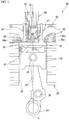
- FIG. 1 is a sectional view taken along a cylinder central axis, which shows a configuration around a cylinder head of a gas engine according to an embodiment of this invention.
- a gas engine 10 is a prechamber-type gas engine.
- the gas engine 10 includes at least a cylinder block 20, a cylinder head 30, and a prechamber member 40.
- the gas engine 10 according to this embodiment is a stationary gas engine used for power generation equipment.
- the cylinder block 20 includes a cylinder 21 having a cylindrical shape.
- the cylinder 21 internally accommodates a piston 22 so that the piston 22 can linearly reciprocate along a central axis C of the cylinder 21.
- the piston 22 is connected to a crankshaft 24 accommodated inside a crankcase (not shown) via a connecting rod 23. Both end portions of the connecting rod 23 are respectively and pivotally connected to the piston 22 and the crankshaft 24 via pins 25 and 26. In this manner, if the piston 22 linearly moves inside the cylinder 21 in the direction along the central axis C, the movement of the piston 22 is converted into a rotary movement of the crankshaft 24 by the connecting rod 23.
- the cylinder head 30 is connected to an end surface 20a on which the cylinder 21 is open in the cylinder block 20. In this manner, the cylinder head 30 blocks the opening of the cylinder 21.
- a roof surface 31 having a flat shape, a semi-spherical shape, or a curved surface shape which is orthogonal to the central axis C of the cylinder 21 is formed in a region facing the cylinder 21, on a surface facing the cylinder block 20 side in the cylinder head 30.
- a main combustion chamber 33 is divided by the cylinder block 20, the cylinder head 30, and the piston 22.
- the cylinder head 30 has an intake port (port) 34 and an exhaust port (port) 35.
- An end portion 34a of the intake port 34 and an end portion 35a of the exhaust port 35 are respectively open on the roof surface 31, and are arranged so as to face the main combustion chamber 33.
- the intake port 34 and the exhaust port 35 are concentrically arranged at an interval in a circumferential direction with respect to the central axis C of the cylinder 21.
- an end portion (not shown) on a side opposite to the main combustion chamber 33 is connected to a mixed gas supply source (not shown).
- Mixed gas of air and combustion gas is supplied to the intake port 34 from the mixed gas supply source.
- an intake valve 36 is disposed in the end portion 34a on the main combustion chamber 33 side. The intake valve 36 is displaced from a closed position to an open position by a valve drive mechanism (not shown). In this manner, the mixed gas supplied from the mixed gas supply source is supplied to the main combustion chamber 33 through the intake port 34.
- an end portion (not shown) on a side opposite to the main combustion chamber 33 is connected to an exhaust gas flow path (not shown).
- an exhaust valve 37 is disposed in the end portion 35a on the main combustion chamber 33 side. The exhaust valve 37 is displaced from a closed position to an open position by a valve drive mechanism (not shown). In this manner, the exhaust gas of the mixed gas combusted in the main combustion chamber 33 is discharged outward via the exhaust gas flow path through the exhaust port 35 from the main combustion chamber 33.
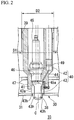
- FIG. 2 is a sectional view taken along the cylinder central axis, which shows a configuration around the prechamber of the gas engine according to this embodiment.
- the prechamber member 40 is disposed in the cylinder head 30.
- the prechamber member 40 forms the prechamber 41 to which prechamber gas is supplied.
- the prechamber member 40 is disposed at the center of the roof surface 31, that is, on the extension line of the central axis C of the cylinder 21.
- the prechamber member 40 is arranged so that the central axis C overlaps the extension line of the central axis C of the cylinder 21. That is, the prechamber member 40 is located at the central portion with respect to the intake port 34 and the exhaust port 35 which are arranged at an interval in the circumferential direction around the central axis C of the cylinder 21.
- the prechamber member 40 includes a prechamber holder 42 and a prechamber cap 43.
- the prechamber holder 42 is disposed by being press-fitted into or being screwed into a prechamber member holding hole 39 formed in the cylinder head 30.
- the central axis of the prechamber holder 42 is arranged so as to overlap the extension line of the central axis C of the cylinder 21.
- the prechamber holder 42 includes a gas introduction path 44, a plug holding hole (plug holding portion) 46, and a cap holding portion 47.
- the gas introduction path 44 introduces the prechamber gas serving as the fuel gas to the prechamber 41 from the outside.
- the plug holding hole 46 is disposed adjacent to the gas introduction path 44.
- the plug holding hole 46 holds an ignition plug 45 which generates a flame by igniting the prechamber gas inside the prechamber 41.
- the cap holding portion 47 holds the prechamber cap 43.
- FIG. 3 is a sectional view showing a structure of the prechamber cap attached to the prechamber holder according to this embodiment.
- the prechamber cap 43 has a first cylindrical portion (end portion) 43a, a second cylindrical portion 43b, and a distal end portion 43c.
- the first cylindrical portion 43a is formed in a cylindrical shape.
- the first cylindrical portion 43a has an outer diameter smaller than an inner diameter of the cap holding portion 47.
- the second cylindrical portion 43b is formed to be continuous with one end of the first cylindrical portion 43a.
- the second cylindrical portion 43b has an outer diameter smaller than that of the first cylindrical portion 43a.
- the distal end portion 43c is formed in a semi-spherical shape which is formed to be continuous with one end of the second cylindrical portion 43b.
- the first cylindrical portion (end portion) 43a, the second cylindrical portion 43b, and the distal end portion 43c are formed as described above. In this manner, on the outer peripheral surface of the prechamber cap 43, a stepped portion 43d is formed between the first cylindrical portion 43a and the second cylindrical portion 43b.
- the prechamber cap 43 is inserted into a cap insertion hole (insertion hole) 38 in which the second cylindrical portion 43b is formed at the center of the roof surface 31 of the cylinder head 30.
- the prechamber cap 43 is installed so that the stepped portion 43d collides with a back surface 31b of the roof surface 31.
- the distal end portion 43c projects into the main combustion chamber 33.
- the prechamber 41 is formed inside the first cylindrical portion 43a, the second cylindrical portion 43b, and the distal end portion 43c of the prechamber cap 43.
- injection holes 43h are formed in the distal end portion 43c of the prechamber cap 43.
- the injection holes 43h inject a flame generated by the ignition plug 45 igniting the prechamber gas inside the prechamber 41, into the main combustion chamber 33.
- a check valve 49 is disposed in the gas introduction path 44 which introduces the prechamber gas serving as the fuel gas to the prechamber 41 from the outside.
- the prechamber gas is injected into the prechamber 41 via the check valve 49.
- the ignition plug 45 ignites and combusts the fuel gas by means of spark discharge.
- the distal end portion 45a of the ignition plug 45 projects into the prechamber 41.
- the ignition plug 45 can generate the spark discharge in the distal end portion 45a.
- the ignition plug 45 generates the spark discharge, thereby generating the flame by igniting and combusting the fuel gas supplied into the prechamber 41 from the gas introduction path 44.
- the flame generated by the ignition is injected into the main combustion chamber 33 through the injection hole 43h of the prechamber cap 43.
- the flame combusts the mixed gas supplied into the main combustion chamber 33 through the intake port 34 (refer to FIG. 1 ).
- the piston 22 linearly moves inside the cylinder 21 along the central axis C, thereby driving the gas engine 10.
- the first cylindrical portion 43a of the prechamber cap 43 is accommodated in the cap holding portion 47. In this manner, the prechamber cap 43 is held by the prechamber holder 42.
- a temporary fastening member 50A is disposed in the prechamber member 40.
- the temporary fastening member 50A includes a pin (projection member) 51 and an insertion groove (insertion-receivable portion) 52.
- the pin 51 projects inward in the radial direction from the inner peripheral surface of the cap holding portion 47 of the prechamber holder 42. At least a distal end portion 51a of the pin 51 is inserted into the insertion groove 52.
- the pin 51 it is possible to use a screw member which penetrates a penetrating screw hole 47h from the outer peripheral surface side of the cap holding portion 47.
- the insertion groove 52 has at least a depth formed in such an extent that the distal end portion 51a of the pin 51 does not interfere with a bottom portion 52b of the insertion groove 52 in a state where the prechamber cap 43 is moved close to the pin 51 side (left side on the paper surface in FIG. 3 ) inside the cap holding portion 47.
- the insertion groove 52 is formed in a long hole shape so as to extend in a direction along the central axis C, on the outer peripheral surface of the first cylindrical portion 43a of the prechamber cap 43.
- the pin 51 in which at least the distal end portion 51a is inserted into the insertion groove 52 is inserted in a state where the pin 51 is movable relative to the insertion groove 52 in the direction along the central axis C.
- a sealing member 54 formed of a rubber-based material is attached between a rear end surface (distal end surface of the end portion) 43e of the first cylindrical portion 43a of the prechamber cap 43 and a bottom surface 47b of the cap holding portion 47.
- a sealing member 55 formed of a rubber-based material is also attached between the stepped portion 43d of the prechamber cap 43 and the back surface 31b of the roof surface 31 of the cylinder head 30.
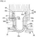
- FIG. 4 is a sectional view showing a movement of the prechamber cap 43 when the prechamber member is attached to the cylinder head.
- the prechamber cap 43 is held in a state where the prechamber cap 43 is movable relative to the prechamber holder 42 inside the cap holding portion 47 in the radial direction and the direction of the central axis C.
- the relatively movable state continues until the prechamber member 40 is completely incorporated in the cylinder head 30.
- the prechamber cap 43 when the prechamber cap 43 is inserted into the cap insertion hole 38, the prechamber cap 43 is in a state where the prechamber cap 43 is movable relative to the prechamber holder 42 in the radial direction and the central axis direction.
- the prechamber cap 43 is interposed between the back surface 31b of the roof surface 31 of the cylinder head 30 and the bottom surface 42b of the prechamber holder 42, via the sealing members 54 and 55.
- the movement of the prechamber cap 43 is restricted in the direction along the central axis C.
- the space S is formed in the radial direction orthogonal to the central axis of the prechamber holder 42, between the cap holding portion 47 and the first cylindrical portion 43a of the prechamber cap 43.
- the prechamber member 40 is assembled in advance as follows.
- the first cylindrical portion 43a of the prechamber cap 43 is accommodated inside the cap holding portion 47 formed in the prechamber holder 42.
- the pin 51 is screwed into the penetrating screw hole 47h from the outer peripheral surface of the cap holding portion 47.
- the distal end portion 51a is inserted into the insertion groove 52 formed on the outer peripheral surface of the cap holding portion 47.
- the prechamber cap 43 is in a state where the prechamber cap 43 is relatively movable inside the cap holding portion 47 in the direction along the central axis C and the radial direction orthogonal to the central axis C.
- the prechamber holder 42 is fixed to the cylinder head 30.
- the prechamber cap 43 When the prechamber cap 43 is inserted into the cap insertion hole 38, the prechamber cap 43 is movable inside the cap holding portion 47 in the radial direction. Therefore, as shown by a two-dot chain line in FIG. 4 , the prechamber cap 43 moves in the radial direction while being aligned with the position of the cap insertion hole 38, and is inserted into the cap insertion hole 38.
- the outer diameter of the first cylindrical portion 43a of the prechamber cap 43 is set to be smaller than the inner diameter of the cap holding portion 47. Accordingly, the prechamber cap 43 is relatively movable inside the cap holding portion 47 in the radial direction. In this manner, when the gas engine 10 is assembled, the prechamber cap 43 moves in the radial direction while being aligned with the position of the cap insertion hole 38. Accordingly, the prechamber cap 43 can be inserted into the cap insertion hole 38. As a result, even if there is a processing error in an outer diameter D1 (refer to FIG. 2 ) of the prechamber holder 42, an inner diameter D2 (refer to FIG.
- the prechamber cap 43 can be accurately installed in the cylinder head 30.
- the gas engine according to this invention is not limited to the above-described embodiment, and includes those which have various modifications added to the above-described embodiment within the scope not departing from the gist of this invention. That is, a specific shape or configuration described in the embodiment is only an example, and can be appropriately modified. Various modified examples are conceivable in the technical scope.
- the modified examples of the above-described embodiment will be described with reference to FIGS. 5A, 5B , 6A, 6B , and 7 .
- the same reference numerals will be given to elements which are the same as those in the above-described embodiment, and a repeated description will be omitted.
- the temporary fastening member 50A is configured to include the pin 51 and the insertion groove 52, but the invention is not limited to this configuration.
- the configuration of the temporary fastening member is not limited in any way as long as the prechamber cap 43 can be held in a state of a single body where the prechamber member 40 is not incorporated in the cylinder head 30, and in a state where the prechamber cap 43 is movable relative to the prechamber holder 42 inside the cap holding portion 47 at least in the radial direction.
- a configuration may be adopted in which a temporary fastening member 50B projects inward in the radial direction from the inner peripheral surface of the cap holding portion 47.
- the temporary fastening member 50B may include a snap ring 56 and the insertion groove 52.
- the snap ring 56 is formed in a C-shape, and is mounted on the inner peripheral surface of the cap holding portion 47.
- the insertion groove 52 is formed to be continuous with the outer peripheral surface of the prechamber cap 43 in the circumferential direction.
- the snap ring 56 is fitted into a ring groove 47m formed to be continuous with the inner peripheral surface of the cap holding portion 47 in the circumferential direction.
- the snap ring 56 and the insertion groove 52 may be disposed so that both of these can be held in a state where the prechamber cap 43 is relatively movable inside the cap holding portion 47 in the direction of the central axis C (refer to FIG. 1 ).
- a temporary fastening member 50C may include a guide groove 57, a temporary fastening groove 58, and a projection portion 59.
- the guide groove 57 is formed on the inner peripheral surface of the cap holding portion 47, and extends in the direction of the central axis C (refer to FIG. 1 ) from the distal end portion 47c of the cap holding portion 47.
- the temporary fastening groove 58 is formed to be continuous from a distal end portion 57a of the guide groove 57, and extends in the circumferential direction of the cap holding portion 47.
- the projection portion 59 is formed on the outer peripheral surface of the first cylindrical portion 43a of the prechamber cap 43, and is inserted into the guide groove 57 and the temporary fastening groove 58.
- the temporary fastening groove 58 is formed to have a groove width which can hold the prechamber cap 43 in a state where the projection portion 59 is inserted into the temporary fastening groove 58, and in a state where the prechamber cap 43 is relatively movable inside the cap holding portion 47 in the direction of the central axis C.
- the first cylindrical portion 43a of the prechamber cap 43 is accommodated in the cap holding portion 47, thereby causing the prechamber holder 42 to hold the prechamber cap 43, but the invention is not limited thereto.
- the prechamber holder 42 may hold the prechamber cap 43 by forming a concave portion 60 on the prechamber cap 43 side and accommodating an end portion 47s of the cap holding portion 47 inside the concave portion 60.
- gas engine 10 may adopt any other configuration as a configuration of each unit other than the holding structure of the prechamber cap 43 with respect to the prechamber holder 42 in the prechamber member 40.
- This invention relates to a gas engine. According to this invention, a position of a cap is more accurately aligned with a cylinder head while a cost increase is suppressed. Therefore, it is possible to prevent environmental friendliness and a fuel consumption rate from being degraded.
Description
- This invention relates to a gas engine including a prechamber and an assembling method for a gas engine.
- Priority is claimed on Japanese Patent Application No.
2013-259377, filed December 16, 2013 - As one type of engines, a gas engine is known which is operated by combusting gaseous fuel (fuel gas) such as natural gas, town gas, and the like. This gas engine can achieve high efficiency and high output performance. Therefore, the gas engine is widely used for mainly regular / emergency power generating engines, construction machinery engines, and engines mounted on ships, railway vehicles, and the like.
- A gas engine is known in which a cylinder head includes a prechamber for ignition. In this gas engine, an air-fuel mixture obtained by mixing fuel gas and air is supplied to a main combustion chamber inside the cylinder head. In addition, the fuel gas is also supplied to the prechamber. Then, if a piston inside the main combustion chamber moves close to the compression top dead center and the fuel gas inside the main combustion chamber is compressed, the fuel gas supplied into the prechamber is ignited by an ignition plug included in the prechamber. This generates a flame from the prechamber, and the flame is injected into the main combustion chamber through a cap disposed in the prechamber. In this case, the flame ignites the air-fuel mixture inside the main combustion chamber, thereby allowing the gas engine to perform a combustion operation (for example, Patent Document 1 or 2)
- Here, the prechamber is configured to include the cap that supplies the flame into the main combustion chamber, and a prechamber holder that forms the prechamber into which the fuel gas is supplied.
- According to the configuration disclosed in Patent Document 1, the prechamber holder (laser ignition plug) is attached to a cylinder head by screwing a male screw formed on an outer peripheral surface of the prechamber holder into a female screw hole formed in the cylinder head. The cap (prechamber module) and the prechamber holder are attached to each other by screwing a male screw formed on an outer peripheral surface of the cap into a female screw hole of a cap attachment portion formed on the prechamber holder side.
-
- Patent Document 1: Published Japanese Translation No.
2012-518120 of the PCT - Patent Document 2 :
JP 2012 047115 A - However, the above-described gas engine has the following problem.
- Without being limited to the gas engine, various components each have a dimensional tolerance which allows design dimensions to have an error within a certain range when the components are manufactured.
- According to the configuration disclosed in Patent Document 1, for example, each dimensional tolerance is also set in an inner diameter of the female screw hole of the cylinder head, an outer diameter of a male screw groove of the outer peripheral surface of the prechamber holder, an outer diameter of the male screw of the cap, and an inner diameter of the female screw hole of the cap attachment portion of the prechamber holder.
- Even if the dimension of the respective inner diameters or outer diameters in these sections falls within the dimensional tolerance, for example, if every error of 0.1 mm occurs in the design dimensions, total errors of four components causes a disadvantage in that a position of the cap is misaligned with a nozzle insertion hole of the cylinder head as much as a maximum of 0.4 mm in a radial direction. In this case, at the time of assembly, there is a possibility that the cap may not smoothly fit into the nozzle insertion hole.
- If the position of the cap is intended to be more accurately aligned with the cylinder head in the gas engine, it is necessary to narrow a range of the dimensional tolerance of each component. However, narrowing the dimensional tolerance of the component leads to an increased manufacturing cost for the component.
- Therefore, in view of the position of the cap being misaligned with the nozzle insertion hole, it is conceivable to dispose a space between the inner peripheral surface of the nozzle insertion hole and the outer peripheral surface of the cap. However, in that case, fuel permeates into the cylinder head through the space. Furthermore, if the permeating fuel which is unburned is discharged as hydrocarbon (HC) together with exhaust gas, this is not environmentally friendly, and a fuel consumption rate per unit time also increases.
- This invention aims to provide a gas engine and an assembling method for a gas engine, in which a position of a cap is more accurately aligned with a cylinder head while a cost increase is suppressed, and which can prevent environmental friendliness and the fuel consumption rate from being degraded.
- According to a first aspect of this invention, a gas engine includes a cylinder head in which multiple intake and exhaust ports open toward a main combustion chamber are formed at an interval in a circumferential direction with respect to a central axis. The gas engine further includes a prechamber cap that projects into the main combustion chamber by being inserted into an insertion hole formed in the cylinder head, that internally has a prechamber, and that supplies a flame generated in the prechamber to the main combustion chamber. The gas engine further includes a prechamber holder that is disposed inside the cylinder head so as to hold the prechamber cap. One of the prechamber cap and the prechamber holder includes a concave portion which accommodates an end portion of the other of the prechamber cap and the prechamber holder so as to be relatively movable in a central axis direction and a radial direction when the prechamber cap is inserted into the insertion hole.
- According to a second aspect of this invention, in the first aspect, the gas engine may further include a temporary fastening member that holds the end portion accommodated in the concave portion so as to be relatively movable in the radial direction and the central axis direction.
- According to a third aspect of this invention, in the gas engine, the temporary fastening member in the second aspect may further include a projection portion which projects inward in the radial direction from an inner peripheral surface of the concave portion, and an insertion-receivable portion which is formed on an outer peripheral surface of the end portion to be accommodated in the concave portion, and into which at least a distal end portion of the projection portion is inserted.
- According to a fourth aspect of this invention, in the gas engine, the insertion-receivable portion in the third aspect may extend in a direction along the central axis. The projection portion may extend in the direction along the central axis, and may be inserted into the insertion-receivable portion in a state where the projection portion is movable relative to the insertion-receivable portion in a direction along the central axis.
- According to a fifth aspect of this invention, in the gas engine, the temporary fastening member in the second aspect may be a C-shaped snap ring which is mounted on the inner peripheral surface of the concave portion so as to project inward in the radial direction from the inner peripheral surface of the concave portion.
- According to a sixth aspect of this invention, in the gas engine, the temporary fastening member in the second aspect may include a guide groove which is formed on the inner peripheral surface of the concave portion, and which extends in the direction along the central axis, a temporary fastening groove which is formed to be continuous with a distal end portion of the guide groove, and which extends in the circumferential direction of the concave portion, and a projection portion which is formed on the outer peripheral surface of the end portion, and which is inserted into the guide groove and the temporary fastening groove.
- According to a seventh aspect of this invention, the gas engine in any one aspect of the first to sixth aspects may include a sealing member disposed between a distal end surface of the end portion and a bottom surface of the concave portion.
- According to an eighth aspect of this invention, there is provided an assembling method for a gas engine including a cylinder head in which multiple intake and exhaust ports open toward a main combustion chamber are formed at an interval in a circumferential direction with respect to a central axis, a prechamber cap that projects into the main combustion chamber by being inserted into an insertion hole formed in the cylinder head, that internally has a prechamber, and that supplies a flame generated in the prechamber to the main combustion chamber, and a prechamber holder that is disposed inside the cylinder head so as to hold the prechamber cap. The method includes a step of causing a concave portion formed in one of the prechamber cap and the prechamber holder to accommodate an end portion of the other of the prechamber cap and the prechamber holder so as to bring the end portion into a state where the end portion is relatively movable inside the concave portion at least in a radial direction orthogonal to the central axis, and a step of inserting the prechamber cap into the insertion hole formed in the cylinder head and fixing the prechamber holder to the cylinder head in a state where the prechamber cap projects into the main combustion chamber.
- According to the above-described gas engine and assembling method for a gas engine, a position of a cap is more accurately aligned with a cylinder head while a cost increase is suppressed. Therefore, it is possible to prevent environmental friendliness and a fuel consumption rate from being degraded.
-
-
FIG. 1 is a sectional view taken along a cylinder central axis, which shows a configuration around a cylinder head of a gas engine according to an embodiment of this invention. -
FIG. 2 is a sectional view taken along the cylinder central axis, which shows a configuration around a prechamber of the above-described gas engine. -
FIG. 3 is a sectional view showing a structure of a prechamber cap attached to a prechamber holder of the above-described gas engine. -
FIG. 4 is a sectional view showing a movement of the prechamber cap when a prechamber member of the above-described gas engine is attached to the cylinder head. -
FIG. 5A is a sectional view showing a modified example of a structure of a prechamber cap attached to a prechamber holder according to the embodiment of this invention. -
FIG. 5B is a view showing a modified example of a structure of the prechamber cap attached to the prechamber holder according to the embodiment of this invention, and is a plan view of a snap ring. -
FIG. 6A is a view showing another modified example of a structure of the prechamber cap attached to the prechamber holder according to the embodiment of this invention, and is a view showing the external appearance of a main portion of the prechamber cap and the prechamber holder. -
FIG. 6B is a view showing another modified example of a structure of the prechamber cap attached to the prechamber holder according to the embodiment of this invention, and is a view showing the external appearance in a state where the prechamber cap is attached to the prechamber holder. -
FIG. 7 is a sectional view showing yet another modified example of a structure of the prechamber cap attached to the prechamber holder according to the embodiment of this invention. - Hereinafter, a gas engine according to an embodiment of this invention will be described with reference to the drawings.
-
FIG. 1 is a sectional view taken along a cylinder central axis, which shows a configuration around a cylinder head of a gas engine according to an embodiment of this invention. - As shown in
FIG. 1 , agas engine 10 is a prechamber-type gas engine. Thegas engine 10 includes at least acylinder block 20, acylinder head 30, and aprechamber member 40. Thegas engine 10 according to this embodiment is a stationary gas engine used for power generation equipment. - The
cylinder block 20 includes acylinder 21 having a cylindrical shape. Thecylinder 21 internally accommodates apiston 22 so that thepiston 22 can linearly reciprocate along a central axis C of thecylinder 21. Thepiston 22 is connected to acrankshaft 24 accommodated inside a crankcase (not shown) via a connectingrod 23. Both end portions of the connectingrod 23 are respectively and pivotally connected to thepiston 22 and thecrankshaft 24 viapins piston 22 linearly moves inside thecylinder 21 in the direction along the central axis C, the movement of thepiston 22 is converted into a rotary movement of thecrankshaft 24 by the connectingrod 23. - The
cylinder head 30 is connected to anend surface 20a on which thecylinder 21 is open in thecylinder block 20. In this manner, thecylinder head 30 blocks the opening of thecylinder 21. - A
roof surface 31 having a flat shape, a semi-spherical shape, or a curved surface shape which is orthogonal to the central axis C of thecylinder 21 is formed in a region facing thecylinder 21, on a surface facing thecylinder block 20 side in thecylinder head 30. - A
main combustion chamber 33 is divided by thecylinder block 20, thecylinder head 30, and thepiston 22. - The
cylinder head 30 has an intake port (port) 34 and an exhaust port (port) 35. Anend portion 34a of theintake port 34 and anend portion 35a of theexhaust port 35 are respectively open on theroof surface 31, and are arranged so as to face themain combustion chamber 33. Theintake port 34 and theexhaust port 35 are concentrically arranged at an interval in a circumferential direction with respect to the central axis C of thecylinder 21. - In the
intake port 34, an end portion (not shown) on a side opposite to themain combustion chamber 33 is connected to a mixed gas supply source (not shown). Mixed gas of air and combustion gas is supplied to theintake port 34 from the mixed gas supply source. In theintake port 34, anintake valve 36 is disposed in theend portion 34a on themain combustion chamber 33 side. Theintake valve 36 is displaced from a closed position to an open position by a valve drive mechanism (not shown). In this manner, the mixed gas supplied from the mixed gas supply source is supplied to themain combustion chamber 33 through theintake port 34. - In the
exhaust port 35, an end portion (not shown) on a side opposite to themain combustion chamber 33 is connected to an exhaust gas flow path (not shown). In theexhaust port 35, anexhaust valve 37 is disposed in theend portion 35a on themain combustion chamber 33 side. Theexhaust valve 37 is displaced from a closed position to an open position by a valve drive mechanism (not shown). In this manner, the exhaust gas of the mixed gas combusted in themain combustion chamber 33 is discharged outward via the exhaust gas flow path through theexhaust port 35 from themain combustion chamber 33. -
FIG. 2 is a sectional view taken along the cylinder central axis, which shows a configuration around the prechamber of the gas engine according to this embodiment. - As shown in
FIGS. 1 and2 , theprechamber member 40 is disposed in thecylinder head 30. Theprechamber member 40 forms theprechamber 41 to which prechamber gas is supplied. Theprechamber member 40 is disposed at the center of theroof surface 31, that is, on the extension line of the central axis C of thecylinder 21. Theprechamber member 40 is arranged so that the central axis C overlaps the extension line of the central axis C of thecylinder 21. That is, theprechamber member 40 is located at the central portion with respect to theintake port 34 and theexhaust port 35 which are arranged at an interval in the circumferential direction around the central axis C of thecylinder 21. - As shown in
FIG. 2 , theprechamber member 40 includes aprechamber holder 42 and aprechamber cap 43. - The
prechamber holder 42 is disposed by being press-fitted into or being screwed into a prechambermember holding hole 39 formed in thecylinder head 30. The central axis of theprechamber holder 42 is arranged so as to overlap the extension line of the central axis C of thecylinder 21. Theprechamber holder 42 includes agas introduction path 44, a plug holding hole (plug holding portion) 46, and acap holding portion 47. - The
gas introduction path 44 introduces the prechamber gas serving as the fuel gas to theprechamber 41 from the outside. - The
plug holding hole 46 is disposed adjacent to thegas introduction path 44. Theplug holding hole 46 holds anignition plug 45 which generates a flame by igniting the prechamber gas inside theprechamber 41. - The
cap holding portion 47 holds theprechamber cap 43. -
FIG. 3 is a sectional view showing a structure of the prechamber cap attached to the prechamber holder according to this embodiment. - As shown in
FIGS. 2 and3 , theprechamber cap 43 has a first cylindrical portion (end portion) 43a, a secondcylindrical portion 43b, and adistal end portion 43c. - The first
cylindrical portion 43a is formed in a cylindrical shape. The firstcylindrical portion 43a has an outer diameter smaller than an inner diameter of thecap holding portion 47. - The second
cylindrical portion 43b is formed to be continuous with one end of the firstcylindrical portion 43a. The secondcylindrical portion 43b has an outer diameter smaller than that of the firstcylindrical portion 43a. - The
distal end portion 43c is formed in a semi-spherical shape which is formed to be continuous with one end of the secondcylindrical portion 43b. - The first cylindrical portion (end portion) 43a, the second
cylindrical portion 43b, and thedistal end portion 43c are formed as described above. In this manner, on the outer peripheral surface of theprechamber cap 43, a steppedportion 43d is formed between the firstcylindrical portion 43a and the secondcylindrical portion 43b. - The
prechamber cap 43 is inserted into a cap insertion hole (insertion hole) 38 in which the secondcylindrical portion 43b is formed at the center of theroof surface 31 of thecylinder head 30. Theprechamber cap 43 is installed so that the steppedportion 43d collides with aback surface 31b of theroof surface 31. In this state, in theprechamber cap 43, thedistal end portion 43c projects into themain combustion chamber 33. Theprechamber 41 is formed inside the firstcylindrical portion 43a, the secondcylindrical portion 43b, and thedistal end portion 43c of theprechamber cap 43. -
Multiple injection holes 43h are formed in thedistal end portion 43c of theprechamber cap 43. The injection holes 43h inject a flame generated by theignition plug 45 igniting the prechamber gas inside theprechamber 41, into themain combustion chamber 33. - As shown in
FIG. 2 , acheck valve 49 is disposed in thegas introduction path 44 which introduces the prechamber gas serving as the fuel gas to theprechamber 41 from the outside. The prechamber gas is injected into theprechamber 41 via thecheck valve 49. - The ignition plug 45 ignites and combusts the fuel gas by means of spark discharge. The
distal end portion 45a of the ignition plug 45 projects into theprechamber 41. The ignition plug 45 can generate the spark discharge in thedistal end portion 45a. The ignition plug 45 generates the spark discharge, thereby generating the flame by igniting and combusting the fuel gas supplied into theprechamber 41 from thegas introduction path 44. The flame generated by the ignition is injected into themain combustion chamber 33 through theinjection hole 43h of theprechamber cap 43. The flame combusts the mixed gas supplied into themain combustion chamber 33 through the intake port 34 (refer toFIG. 1 ). Then, thepiston 22 linearly moves inside thecylinder 21 along the central axis C, thereby driving thegas engine 10. - As shown in
FIG. 3 , in the above-describedprechamber member 40, the firstcylindrical portion 43a of theprechamber cap 43 is accommodated in thecap holding portion 47. In this manner, theprechamber cap 43 is held by theprechamber holder 42. - A
temporary fastening member 50A is disposed in theprechamber member 40. Thetemporary fastening member 50A includes a pin (projection member) 51 and an insertion groove (insertion-receivable portion) 52. - The
pin 51 projects inward in the radial direction from the inner peripheral surface of thecap holding portion 47 of theprechamber holder 42. At least adistal end portion 51a of thepin 51 is inserted into theinsertion groove 52. For example, as thepin 51, it is possible to use a screw member which penetrates a penetratingscrew hole 47h from the outer peripheral surface side of thecap holding portion 47. - The
insertion groove 52 has at least a depth formed in such an extent that thedistal end portion 51a of thepin 51 does not interfere with abottom portion 52b of theinsertion groove 52 in a state where theprechamber cap 43 is moved close to thepin 51 side (left side on the paper surface inFIG. 3 ) inside thecap holding portion 47. Theinsertion groove 52 is formed in a long hole shape so as to extend in a direction along the central axis C, on the outer peripheral surface of the firstcylindrical portion 43a of theprechamber cap 43. Thepin 51 in which at least thedistal end portion 51a is inserted into theinsertion groove 52 is inserted in a state where thepin 51 is movable relative to theinsertion groove 52 in the direction along the central axis C. - A sealing
member 54 formed of a rubber-based material is attached between a rear end surface (distal end surface of the end portion) 43e of the firstcylindrical portion 43a of theprechamber cap 43 and abottom surface 47b of thecap holding portion 47. - A sealing
member 55 formed of a rubber-based material is also attached between the steppedportion 43d of theprechamber cap 43 and theback surface 31b of theroof surface 31 of thecylinder head 30. -
FIG. 4 is a sectional view showing a movement of theprechamber cap 43 when the prechamber member is attached to the cylinder head. - According to the
temporary fastening member 50A as described above, in a state of a single body in which theprechamber member 40 is not incorporated in thecylinder head 30 as shown inFIG. 4 , theprechamber cap 43 is held in a state where theprechamber cap 43 is movable relative to theprechamber holder 42 inside thecap holding portion 47 in the radial direction and the direction of the central axis C. The relatively movable state continues until theprechamber member 40 is completely incorporated in thecylinder head 30. That is, when theprechamber cap 43 is inserted into thecap insertion hole 38, theprechamber cap 43 is in a state where theprechamber cap 43 is movable relative to theprechamber holder 42 in the radial direction and the central axis direction. - As shown in
FIG. 3 , in a state where theprechamber member 40 is incorporated in thecylinder head 30, theprechamber cap 43 is interposed between theback surface 31b of theroof surface 31 of thecylinder head 30 and the bottom surface 42b of theprechamber holder 42, via the sealingmembers prechamber cap 43 is restricted in the direction along the central axis C. The space S is formed in the radial direction orthogonal to the central axis of theprechamber holder 42, between thecap holding portion 47 and the firstcylindrical portion 43a of theprechamber cap 43. - In order to assemble the
cylinder head 30 of thegas engine 10 configured as described above, theprechamber member 40 is assembled in advance as follows. - First, the first
cylindrical portion 43a of theprechamber cap 43 is accommodated inside thecap holding portion 47 formed in theprechamber holder 42. In this state, thepin 51 is screwed into the penetratingscrew hole 47h from the outer peripheral surface of thecap holding portion 47. Thedistal end portion 51a is inserted into theinsertion groove 52 formed on the outer peripheral surface of thecap holding portion 47. In this manner, theprechamber cap 43 is in a state where theprechamber cap 43 is relatively movable inside thecap holding portion 47 in the direction along the central axis C and the radial direction orthogonal to the central axis C. - Thereafter, in a state where the
prechamber cap 43 of the assembledprechamber member 40 is inserted into thecap insertion hole 38 formed in thecylinder head 30 and is caused to project into themain combustion chamber 33, theprechamber holder 42 is fixed to thecylinder head 30. - When the
prechamber cap 43 is inserted into thecap insertion hole 38, theprechamber cap 43 is movable inside thecap holding portion 47 in the radial direction. Therefore, as shown by a two-dot chain line inFIG. 4 , theprechamber cap 43 moves in the radial direction while being aligned with the position of thecap insertion hole 38, and is inserted into thecap insertion hole 38. - Therefore, according to the gas engine in the above-described embodiment, the outer diameter of the first
cylindrical portion 43a of theprechamber cap 43 is set to be smaller than the inner diameter of thecap holding portion 47. Accordingly, theprechamber cap 43 is relatively movable inside thecap holding portion 47 in the radial direction. In this manner, when thegas engine 10 is assembled, theprechamber cap 43 moves in the radial direction while being aligned with the position of thecap insertion hole 38. Accordingly, theprechamber cap 43 can be inserted into thecap insertion hole 38. As a result, even if there is a processing error in an outer diameter D1 (refer toFIG. 2 ) of theprechamber holder 42, an inner diameter D2 (refer toFIG. 2 ) of the prechambermember holding hole 39, an outer diameter D3 (refer toFIG. 3 ) of theprechamber cap 43, and an inner diameter D4 (refer toFIG. 3 ) of thecap holding portion 47, theprechamber cap 43 can be accurately installed in thecylinder head 30. - Furthermore, it is not necessary to particularly improve accuracy in processing the
prechamber holder 42, the prechambermember holding hole 39, theprechamber cap 43, and thecap holding portion 47. Accordingly, it is possible to suppress a cost increase. - In addition, it is not necessary to maintain the space between the inner peripheral surface of the
cap insertion hole 38 and the outer peripheral surface of theprechamber cap 43. Therefore, it is possible to prevent environmental friendliness and a fuel consumption rate from being degraded without causing the unburned fuel to leak from the space. - The gas engine according to this invention is not limited to the above-described embodiment, and includes those which have various modifications added to the above-described embodiment within the scope not departing from the gist of this invention. That is, a specific shape or configuration described in the embodiment is only an example, and can be appropriately modified. Various modified examples are conceivable in the technical scope. Hereinafter, the modified examples of the above-described embodiment will be described with reference to
FIGS. 5A, 5B ,6A, 6B , and7 . In the modified examples inFIGS. 5A, 5B ,6A, 6B , and7 , the same reference numerals will be given to elements which are the same as those in the above-described embodiment, and a repeated description will be omitted. - For example, in the above-described embodiment, the
temporary fastening member 50A is configured to include thepin 51 and theinsertion groove 52, but the invention is not limited to this configuration. The configuration of the temporary fastening member is not limited in any way as long as theprechamber cap 43 can be held in a state of a single body where theprechamber member 40 is not incorporated in thecylinder head 30, and in a state where theprechamber cap 43 is movable relative to theprechamber holder 42 inside thecap holding portion 47 at least in the radial direction. - For example, as shown in
FIGS. 5A and 5B , a configuration may be adopted in which atemporary fastening member 50B projects inward in the radial direction from the inner peripheral surface of thecap holding portion 47. For example, thetemporary fastening member 50B may include asnap ring 56 and theinsertion groove 52. For example, thesnap ring 56 is formed in a C-shape, and is mounted on the inner peripheral surface of thecap holding portion 47. Theinsertion groove 52 is formed to be continuous with the outer peripheral surface of theprechamber cap 43 in the circumferential direction. Thesnap ring 56 is fitted into aring groove 47m formed to be continuous with the inner peripheral surface of thecap holding portion 47 in the circumferential direction. - In this case, the
snap ring 56 and theinsertion groove 52 may be disposed so that both of these can be held in a state where theprechamber cap 43 is relatively movable inside thecap holding portion 47 in the direction of the central axis C (refer toFIG. 1 ). - In addition, as shown in
FIGS. 6A and 6B , atemporary fastening member 50C may include aguide groove 57, atemporary fastening groove 58, and aprojection portion 59. Here, theguide groove 57 is formed on the inner peripheral surface of thecap holding portion 47, and extends in the direction of the central axis C (refer toFIG. 1 ) from thedistal end portion 47c of thecap holding portion 47. Thetemporary fastening groove 58 is formed to be continuous from adistal end portion 57a of theguide groove 57, and extends in the circumferential direction of thecap holding portion 47. Theprojection portion 59 is formed on the outer peripheral surface of the firstcylindrical portion 43a of theprechamber cap 43, and is inserted into theguide groove 57 and thetemporary fastening groove 58. - As shown in
FIG. 6B , thetemporary fastening groove 58 is formed to have a groove width which can hold theprechamber cap 43 in a state where theprojection portion 59 is inserted into thetemporary fastening groove 58, and in a state where theprechamber cap 43 is relatively movable inside thecap holding portion 47 in the direction of the central axis C. - Furthermore, in the above-described embodiment, the first
cylindrical portion 43a of theprechamber cap 43 is accommodated in thecap holding portion 47, thereby causing theprechamber holder 42 to hold theprechamber cap 43, but the invention is not limited thereto. For example, as shown inFIG. 7 , theprechamber holder 42 may hold theprechamber cap 43 by forming aconcave portion 60 on theprechamber cap 43 side and accommodating anend portion 47s of thecap holding portion 47 inside theconcave portion 60. - In addition, the
gas engine 10 according to the above-described embodiment may adopt any other configuration as a configuration of each unit other than the holding structure of theprechamber cap 43 with respect to theprechamber holder 42 in theprechamber member 40. - This invention relates to a gas engine. According to this invention, a position of a cap is more accurately aligned with a cylinder head while a cost increase is suppressed. Therefore, it is possible to prevent environmental friendliness and a fuel consumption rate from being degraded.
-
- 10 GAS ENGINE
- 20 CYLINDER BLOCK
- 30 CYLINDER HEAD
- 31 ROOF SURFACE
- 31b BACK SURFACE
- 33 MAIN COMBUSTION CHAMBER
- 34 INTAKE PORT (PORT)
- 35 EXHAUST PORT (PORT)
- 38 CAP INSERTION HOLE (INSERTION HOLE)
- 39 PRECHAMBER MEMBER HOLDING HOLE
- 40 PRECHAMBER MEMBER
- 41 PRECHAMBER
- 42 PRECHAMBER HOLDER
- 42b BOTTOM SURFACE
- 43 PRECHAMBER CAP
- 43a FIRST CYLINDRICAL PORTION (END PORTION)
- 43b SECOND CYLINDRICAL PORTION
- 43c DISTAL END PORTION
- 43d STEPPED PORTION
- 43e REAR END SURFACE
- 43h INJECTION HOLE
- 47 CAP HOLDING PORTION (CONCAVE PORTION)
- 47b BOTTOM SURFACE
- 50A, 50B, 50C TEMPORARY FASTENING MEMBER
- 51 PIN (PROJECTION MEMBER)
- 51a DISTAL END PORTION
- 52 INSERTION GROOVE (INSERTION-RECEIVABLE PORTION)
- 52b BOTTOM PORTION
- 54 SEALING MEMBER
- 56 SNAP RING
- 57 GUIDE GROOVE
- 57a DISTAL END PORTION
- 58 TEMPORARY FASTENING GROOVE
- 59 PROJECTION PORTION
- 60 CONCAVE PORTION
- C CENTRAL AXIS
- S SPACE
Claims (6)
- A gas engine (10) comprising:a cylinder head (30) that is connected to the end surface (20a) on which a cylinder (21) has an opening and blocks the opening of the cylinder (21); anda prechamber member (40) that is disposed in the cylinder head (30), whereinthe cylinder head (30) has a roof surface (31) in a region facing the cylinder (21),the cylinder head (30) has multiple intake and exhaust ports (34, 35) open toward a main combustion chamber (33) and formed at an interval in a circumferential direction with respect to a central axis (C) of the cylinder (21) and has an insertion hole (38) formed in the roof surface (31),the prechamber member (40) includesa prechamber cap (43) that projects into the main combustion chamber (33) by being inserted into the insertion hole (38), that internally has a prechamber (41), and that supplies a flame generated in the prechamber (41) to the main combustion chamber (33); anda prechamber holder (42) that is disposed inside the cylinder head (30),the prechamber cap (43) is interposed between a back surface (31 b) of the roof surface (31) and the prechamber holder (42), one of the prechamber cap (43) and the prechamber holder (42) includes a concave portion (47, 60) which accommodates an end portion (43a, 47s) of the other of the prechamber cap (43) and the prechamber holder (42) so as to be relatively movable in a central axis direction and a radial direction until the prechamber member (40) is completely incorporated in the cylinder head (30).
- The gas engine (10) according to claim 1, further comprising:a temporary fastening member (50A, 50B, 50C) that holds the end portion (43a, 47s) to be accommodated in the concave portion (47, 60) so as to be relatively movable in the radial direction and the central axis direction, whereineither the temporary fastening member (50A, 50B) includesa projection portion (51, 56) which projects inward in the radial direction from an inner peripheral surface of the concave portion (47, 60), andan insertion-receivable portion (52) which is formed on an outer peripheral surface of the end portion (43a, 47s) to be accommodated in the concave portion (47, 60), and into which at least a distal end portion (51a) of the projection portion (51, 56) is inserted;or the temporary fastening member (50C) includesa guide groove (57) which is formed on the inner peripheral surface of the concave portion (47), and which extends in the direction along the central axis (C),a temporary fastening groove (58) which is formed to be continuous with a distal end portion (57a) of the guide groove (57), and which extends in the circumferential direction of the concave portion (47), anda projection portion (59) which is formed on the outer peripheral surface of the end portion (43a), and which is inserted into the guide groove (57) and the temporary fastening groove (58).
- The gas engine (10) according to claim 2, wherein
the insertion-receivable portion (52) extends in a direction along the central axis (C), and the prechamber member (40) is configured to allow the projection portion (51) to move relatively to the insertion-receivable portion (52) in the direction along the central axis (C). - The gas engine (10) according to claim 2, wherein
the projection portion is a C-shaped snap ring (56) which is mounted on the inner peripheral surface of the concave portion (47, 60). - The gas engine (10) according to any one of claims 1 to 4, further comprising:
a sealing member (54) disposed between a distal end surface of the end portion (43a, 47s) and a bottom surface of the concave portion (47, 60). - An assembling method for a gas engine (10) including:a cylinder head (30) that is connected to the end surface (20a) on which a cylinder (21) has an opening and blocks the opening of the cylinder (21); anda prechamber member (40) that is disposed in the cylinder head (30), whereinthe cylinder head (30) has a roof surface (31) in a region facing the cylinder (21),the cylinder head (30) has multiple intake and exhaust ports (34, 35) open toward a main combustion chamber (33) and formed at an interval in a circumferential direction with respect to a central axis (C) of the cylinder (21) and has an insertion hole (38) formed in the roof surface (31), andthe prechamber member (40) includesa prechamber cap (43) that projects into the main combustion chamber (33) by being inserted into the insertion hole (38), that internally has a prechamber (41), and that supplies a flame generated in the prechamber (41) to the main combustion chamber (33), anda prechamber holder (42) that is disposed inside the cylinder head (30), the method comprising:a step of causing a concave portion (47, 60) formed in one of the prechamber cap (43) and the prechamber holder (42) to accommodate an end portion (43a, 47s) of the other of the prechamber cap and the prechamber holder, so as to bring the end portion (43a, 47s) into a state where the end portion (43a, 47s) is relatively movable inside the concave portion (47, 60) at least in a radial direction orthogonal to the central axis, until the prechamber member (40) is completely incorporated in the cylinder head (30); anda step of inserting the prechamber cap (43) into the insertion hole (38) and fixing the prechamber holder (42) to the cylinder head (30) in a state where the prechamber cap (43) projects into the main combustion chamber (33), so as to make the prechamber cap (43) interposed between a back surface (31b) of the roof surface (31) and the prechamber holder (42).
Applications Claiming Priority (2)
| Application Number | Priority Date | Filing Date | Title |
|---|---|---|---|
| JP2013259377A JP2015117582A (en) | 2013-12-16 | 2013-12-16 | Gas engine and assembling method of gas engine |
| PCT/JP2014/081826 WO2015093279A1 (en) | 2013-12-16 | 2014-12-02 | Gas engine and assembling method for gas engine |
Publications (3)
| Publication Number | Publication Date |
|---|---|
| EP3085918A1 EP3085918A1 (en) | 2016-10-26 |
| EP3085918A4 EP3085918A4 (en) | 2017-08-23 |
| EP3085918B1 true EP3085918B1 (en) | 2019-06-26 |
Family
ID=53402628
Family Applications (1)
| Application Number | Title | Priority Date | Filing Date |
|---|---|---|---|
| EP14871621.0A Active EP3085918B1 (en) | 2013-12-16 | 2014-12-02 | Gas engine and assembling method for gas engine |
Country Status (5)
| Country | Link |
|---|---|
| US (1) | US10077708B2 (en) |
| EP (1) | EP3085918B1 (en) |
| JP (1) | JP2015117582A (en) |
| CN (1) | CN105829675B (en) |
| WO (1) | WO2015093279A1 (en) |
Families Citing this family (5)
| Publication number | Priority date | Publication date | Assignee | Title |
|---|---|---|---|---|
| JP6796471B2 (en) * | 2016-12-08 | 2020-12-09 | 三菱重工エンジン&ターボチャージャ株式会社 | Sub-chamber gas engine |
| JP6895243B2 (en) * | 2016-12-08 | 2021-06-30 | 三菱重工エンジン&ターボチャージャ株式会社 | Sub-chamber gas engine |
| US10724423B2 (en) * | 2017-02-16 | 2020-07-28 | Caterpillar Inc. | Vented pre-chamber assembly for an engine |
| JP7257236B2 (en) * | 2019-04-22 | 2023-04-13 | 三菱重工エンジン&ターボチャージャ株式会社 | pre-chamber engine |
| DE102020133717A1 (en) * | 2020-12-16 | 2022-06-23 | Bayerische Motoren Werke Aktiengesellschaft | Ignition device with a prechamber coupled to an ignition source so that it can rotate without offset, internal combustion engine with an ignition device and motor vehicle with an internal combustion engine |
Family Cites Families (30)
| Publication number | Priority date | Publication date | Assignee | Title |
|---|---|---|---|---|
| US2292409A (en) * | 1939-05-11 | 1942-08-11 | George K Steward | Internal combustion engine |
| US3117564A (en) * | 1961-04-13 | 1964-01-14 | Walker Mfg Co | Fuel injector-igniter |
| AT279232B (en) * | 1967-11-09 | 1970-02-25 | Peter Florjancic | Small lighter |
| DE2416804C2 (en) | 1974-04-06 | 1982-12-30 | Daimler-Benz Ag, 7000 Stuttgart | Piston internal combustion engine |
| US4029075A (en) * | 1974-11-13 | 1977-06-14 | Toyota Jidosha Kogyo Kabushiki Kaisha | Combustion apparatus for an internal combustion engine |
| DE2705353C2 (en) * | 1977-02-09 | 1986-06-26 | Daimler-Benz Ag, 7000 Stuttgart | Component with variable thermal conductivity or a corresponding component cross-section |
| DE3123398C2 (en) * | 1981-06-12 | 1985-04-25 | MTU Motoren- und Turbinen-Union München GmbH, 8000 München | Pre-combustion chamber for diesel engines |
| DE3307109A1 (en) * | 1982-08-14 | 1984-03-15 | Robert Bosch Gmbh, 7000 Stuttgart | DEVICE FOR INJECTING FUEL INTO COMBUSTION ROOMS, IN PARTICULAR SELF-IGNITION COMBUSTION ENGINES |
| US4784098A (en) * | 1987-07-20 | 1988-11-15 | Artman Noel G | Internal combustion engine utilizing stratified charge combustion process |
| US5662082A (en) * | 1995-12-05 | 1997-09-02 | Compressor Engineering Corporation | Pre-combustion chamber for internal combustion engine and method of manufacture thereof |
| DE19703309C1 (en) * | 1997-01-30 | 1998-08-13 | Man B & W Diesel Ag | Precombustion chamber e.g. for LPG- or diesel motor of vehicle |
| US5778849A (en) * | 1997-05-05 | 1998-07-14 | Chrysler Corporation | Insulated precombustion chamber |
| US6016785A (en) * | 1998-10-01 | 2000-01-25 | Caterpillar Inc. | Pre-combustion chamber assembly and method |
| US6513483B2 (en) * | 2001-02-07 | 2003-02-04 | Cooper Cameron Corporation | Pre-combustion chamber for an internal combustion engine |
| JP3872704B2 (en) | 2002-03-04 | 2007-01-24 | 三菱重工業株式会社 | Fuel injection valve cooling structure |
| US20050211217A1 (en) * | 2004-03-23 | 2005-09-29 | Boley William C | Pre-chambered type spark plug with pre-chamber entirely below a bottom surface of a cylinder head |
| WO2005121522A1 (en) * | 2004-06-10 | 2005-12-22 | Ichiro Kamimura | Independent combustion chamber-type internal combustion engine |
| NO322345B1 (en) * | 2004-09-27 | 2006-09-18 | Rolls Royce Marine As | Device at a front chamber of a gas engine |
| US7270107B2 (en) * | 2006-01-20 | 2007-09-18 | Cameron International Corporation | Bolted pre-combustion chamber |
| US20070236122A1 (en) * | 2006-04-10 | 2007-10-11 | Borror Bruce M | Pre-chamber type spark plug |
| DE102007015036B4 (en) * | 2007-03-29 | 2008-11-20 | Multitorch Gmbh | Laser ignition for gas mixtures |
| JP5060353B2 (en) | 2008-03-14 | 2012-10-31 | 大阪瓦斯株式会社 | Sub-chamber engine |
| JP5167108B2 (en) | 2008-12-24 | 2013-03-21 | 三菱重工業株式会社 | Gas engine with spark plug |
| DE102009000956A1 (en) | 2009-02-18 | 2010-08-19 | Robert Bosch Gmbh | Laser spark plug and pre-chamber module for this |
| US8662053B2 (en) * | 2009-12-22 | 2014-03-04 | Cummins Inc. | Pre-combustion device for an internal combustion engine |
| JP2012047115A (en) * | 2010-08-27 | 2012-03-08 | Toyota Industries Corp | Auxiliary chamber type gas engine |
| JP5562927B2 (en) * | 2011-11-30 | 2014-07-30 | 三菱重工業株式会社 | Gas engine subchamber gas supply device |
| US9217360B2 (en) * | 2011-12-01 | 2015-12-22 | Cummins Intellectual Property, Inc. | Prechamber device for internal combustion engine |
| US9797296B2 (en) * | 2013-03-15 | 2017-10-24 | Cummins Inc. | Pre-chamber for internal combustion engine |
| EP2977582B1 (en) * | 2014-07-22 | 2018-03-28 | Caterpillar Energy Solutions GmbH | Ignition device with pre-combustion chamber |
-
2013
- 2013-12-16 JP JP2013259377A patent/JP2015117582A/en active Pending
-
2014
- 2014-12-02 CN CN201480068421.6A patent/CN105829675B/en not_active Expired - Fee Related
- 2014-12-02 WO PCT/JP2014/081826 patent/WO2015093279A1/en active Application Filing
- 2014-12-02 US US15/104,505 patent/US10077708B2/en active Active
- 2014-12-02 EP EP14871621.0A patent/EP3085918B1/en active Active
Non-Patent Citations (1)
| Title |
|---|
| None * |
Also Published As
| Publication number | Publication date |
|---|---|
| WO2015093279A1 (en) | 2015-06-25 |
| EP3085918A4 (en) | 2017-08-23 |
| CN105829675A (en) | 2016-08-03 |
| US20160312685A1 (en) | 2016-10-27 |
| CN105829675B (en) | 2018-09-28 |
| US10077708B2 (en) | 2018-09-18 |
| JP2015117582A (en) | 2015-06-25 |
| EP3085918A1 (en) | 2016-10-26 |
Similar Documents
| Publication | Publication Date | Title |
|---|---|---|
| EP3085918B1 (en) | Gas engine and assembling method for gas engine | |
| EP3012444B1 (en) | Pre-combustion chamber assembly for internal combustion engines | |
| WO2013153842A1 (en) | 2-cycle gas engine | |
| US10968814B2 (en) | Internal combustion engine for a motor vehicle | |
| US20080092844A1 (en) | Sealing Device | |
| JP2014062484A (en) | Prechamber gas engine | |
| JP2012216507A (en) | Pre-chamber spark plug | |
| JP5765819B2 (en) | 2-cycle gas engine | |
| US20050092285A1 (en) | System and method for improving ignitability of dilute combustion mixtures | |
| NO992306L (en) | Lean-burning gas engine | |
| EP3118433B1 (en) | Pre-combustion chamber assembly for internal combustion engines | |
| US20190195120A1 (en) | Internal combustion engine | |
| JP5711250B2 (en) | Engine with fuel injection device | |
| JP2009270541A (en) | Engine and spark plug for engine | |
| WO2015093309A1 (en) | Gas engine | |
| WO2017221705A1 (en) | Ignition device for internal combustion engine | |
| JP7257236B2 (en) | pre-chamber engine | |
| CN107110003B (en) | Internal combustion engine, prechamber insert and fuel injector | |
| JP2009270542A (en) | Engine and spark plug for engine | |
| KR20140127445A (en) | Installation structure of combustion pressure sensor into cylinder head for dual fuel engine | |
| KR101205239B1 (en) | Configuration of cylinder head for a gasoline direct injection engine with a separted type spark plug | |
| JP4487850B2 (en) | Fuel injection valve mounting structure | |
| JP2016114013A (en) | Intake port heat insulation structure of internal combustion engine | |
| KR20080086275A (en) | An assembly for retrofitting a diesel engine | |
| KR20100015052A (en) | Mounting structure of fuel pump in gasoline direct injection engine |
Legal Events
| Date | Code | Title | Description |
|---|---|---|---|
| PUAI | Public reference made under article 153(3) epc to a published international application that has entered the european phase |
Free format text: ORIGINAL CODE: 0009012 |
|
| 17P | Request for examination filed |
Effective date: 20160616 |
|
| AK | Designated contracting states |
Kind code of ref document: A1 Designated state(s): AL AT BE BG CH CY CZ DE DK EE ES FI FR GB GR HR HU IE IS IT LI LT LU LV MC MK MT NL NO PL PT RO RS SE SI SK SM TR |
|
| AX | Request for extension of the european patent |
Extension state: BA ME |
|
| DAX | Request for extension of the european patent (deleted) | ||
| A4 | Supplementary search report drawn up and despatched |
Effective date: 20170720 |
|
| RIC1 | Information provided on ipc code assigned before grant |
Ipc: F02B 19/12 20060101ALI20170714BHEP Ipc: F02B 19/16 20060101AFI20170714BHEP Ipc: F02M 21/02 20060101ALI20170714BHEP |
|
| STAA | Information on the status of an ep patent application or granted ep patent |
Free format text: STATUS: EXAMINATION IS IN PROGRESS |
|
| 17Q | First examination report despatched |
Effective date: 20180327 |
|
| RAP1 | Party data changed (applicant data changed or rights of an application transferred) |
Owner name: MITSUBISHI HEAVY INDUSTRIES ENGINE & TURBOCHARGER, |
|
| GRAP | Despatch of communication of intention to grant a patent |
Free format text: ORIGINAL CODE: EPIDOSNIGR1 |
|
| STAA | Information on the status of an ep patent application or granted ep patent |
Free format text: STATUS: GRANT OF PATENT IS INTENDED |
|
| INTG | Intention to grant announced |
Effective date: 20181206 |
|
| GRAJ | Information related to disapproval of communication of intention to grant by the applicant or resumption of examination proceedings by the epo deleted |
Free format text: ORIGINAL CODE: EPIDOSDIGR1 |
|
| STAA | Information on the status of an ep patent application or granted ep patent |
Free format text: STATUS: EXAMINATION IS IN PROGRESS |
|
| GRAR | Information related to intention to grant a patent recorded |
Free format text: ORIGINAL CODE: EPIDOSNIGR71 |
|
| GRAS | Grant fee paid |
Free format text: ORIGINAL CODE: EPIDOSNIGR3 |
|
| STAA | Information on the status of an ep patent application or granted ep patent |
Free format text: STATUS: GRANT OF PATENT IS INTENDED |
|
| INTC | Intention to grant announced (deleted) | ||
| GRAA | (expected) grant |
Free format text: ORIGINAL CODE: 0009210 |
|
| STAA | Information on the status of an ep patent application or granted ep patent |
Free format text: STATUS: THE PATENT HAS BEEN GRANTED |
|
| AK | Designated contracting states |
Kind code of ref document: B1 Designated state(s): AL AT BE BG CH CY CZ DE DK EE ES FI FR GB GR HR HU IE IS IT LI LT LU LV MC MK MT NL NO PL PT RO RS SE SI SK SM TR |
|
| INTG | Intention to grant announced |
Effective date: 20190520 |
|
| REG | Reference to a national code |
Ref country code: GB Ref legal event code: FG4D |
|
| REG | Reference to a national code |
Ref country code: CH Ref legal event code: EP |
|
| REG | Reference to a national code |
Ref country code: AT Ref legal event code: REF Ref document number: 1148536 Country of ref document: AT Kind code of ref document: T Effective date: 20190715 |
|
| REG | Reference to a national code |
Ref country code: DE Ref legal event code: R096 Ref document number: 602014049267 Country of ref document: DE |
|
| REG | Reference to a national code |
Ref country code: IE Ref legal event code: FG4D |
|
| REG | Reference to a national code |
Ref country code: NL Ref legal event code: MP Effective date: 20190626 |
|
| PG25 | Lapsed in a contracting state [announced via postgrant information from national office to epo] |
Ref country code: NO Free format text: LAPSE BECAUSE OF FAILURE TO SUBMIT A TRANSLATION OF THE DESCRIPTION OR TO PAY THE FEE WITHIN THE PRESCRIBED TIME-LIMIT Effective date: 20190926 Ref country code: HR Free format text: LAPSE BECAUSE OF FAILURE TO SUBMIT A TRANSLATION OF THE DESCRIPTION OR TO PAY THE FEE WITHIN THE PRESCRIBED TIME-LIMIT Effective date: 20190626 Ref country code: LT Free format text: LAPSE BECAUSE OF FAILURE TO SUBMIT A TRANSLATION OF THE DESCRIPTION OR TO PAY THE FEE WITHIN THE PRESCRIBED TIME-LIMIT Effective date: 20190626 Ref country code: AL Free format text: LAPSE BECAUSE OF FAILURE TO SUBMIT A TRANSLATION OF THE DESCRIPTION OR TO PAY THE FEE WITHIN THE PRESCRIBED TIME-LIMIT Effective date: 20190626 Ref country code: SE Free format text: LAPSE BECAUSE OF FAILURE TO SUBMIT A TRANSLATION OF THE DESCRIPTION OR TO PAY THE FEE WITHIN THE PRESCRIBED TIME-LIMIT Effective date: 20190626 Ref country code: FI Free format text: LAPSE BECAUSE OF FAILURE TO SUBMIT A TRANSLATION OF THE DESCRIPTION OR TO PAY THE FEE WITHIN THE PRESCRIBED TIME-LIMIT Effective date: 20190626 |
|
| REG | Reference to a national code |
Ref country code: LT Ref legal event code: MG4D |
|
| PG25 | Lapsed in a contracting state [announced via postgrant information from national office to epo] |
Ref country code: LV Free format text: LAPSE BECAUSE OF FAILURE TO SUBMIT A TRANSLATION OF THE DESCRIPTION OR TO PAY THE FEE WITHIN THE PRESCRIBED TIME-LIMIT Effective date: 20190626 Ref country code: GR Free format text: LAPSE BECAUSE OF FAILURE TO SUBMIT A TRANSLATION OF THE DESCRIPTION OR TO PAY THE FEE WITHIN THE PRESCRIBED TIME-LIMIT Effective date: 20190927 Ref country code: RS Free format text: LAPSE BECAUSE OF FAILURE TO SUBMIT A TRANSLATION OF THE DESCRIPTION OR TO PAY THE FEE WITHIN THE PRESCRIBED TIME-LIMIT Effective date: 20190626 Ref country code: BG Free format text: LAPSE BECAUSE OF FAILURE TO SUBMIT A TRANSLATION OF THE DESCRIPTION OR TO PAY THE FEE WITHIN THE PRESCRIBED TIME-LIMIT Effective date: 20190926 |
|
| REG | Reference to a national code |
Ref country code: AT Ref legal event code: MK05 Ref document number: 1148536 Country of ref document: AT Kind code of ref document: T Effective date: 20190626 |
|
| PG25 | Lapsed in a contracting state [announced via postgrant information from national office to epo] |
Ref country code: RO Free format text: LAPSE BECAUSE OF FAILURE TO SUBMIT A TRANSLATION OF THE DESCRIPTION OR TO PAY THE FEE WITHIN THE PRESCRIBED TIME-LIMIT Effective date: 20190626 Ref country code: SK Free format text: LAPSE BECAUSE OF FAILURE TO SUBMIT A TRANSLATION OF THE DESCRIPTION OR TO PAY THE FEE WITHIN THE PRESCRIBED TIME-LIMIT Effective date: 20190626 Ref country code: CZ Free format text: LAPSE BECAUSE OF FAILURE TO SUBMIT A TRANSLATION OF THE DESCRIPTION OR TO PAY THE FEE WITHIN THE PRESCRIBED TIME-LIMIT Effective date: 20190626 Ref country code: PT Free format text: LAPSE BECAUSE OF FAILURE TO SUBMIT A TRANSLATION OF THE DESCRIPTION OR TO PAY THE FEE WITHIN THE PRESCRIBED TIME-LIMIT Effective date: 20191028 Ref country code: NL Free format text: LAPSE BECAUSE OF FAILURE TO SUBMIT A TRANSLATION OF THE DESCRIPTION OR TO PAY THE FEE WITHIN THE PRESCRIBED TIME-LIMIT Effective date: 20190626 Ref country code: EE Free format text: LAPSE BECAUSE OF FAILURE TO SUBMIT A TRANSLATION OF THE DESCRIPTION OR TO PAY THE FEE WITHIN THE PRESCRIBED TIME-LIMIT Effective date: 20190626 Ref country code: AT Free format text: LAPSE BECAUSE OF FAILURE TO SUBMIT A TRANSLATION OF THE DESCRIPTION OR TO PAY THE FEE WITHIN THE PRESCRIBED TIME-LIMIT Effective date: 20190626 |
|
| PG25 | Lapsed in a contracting state [announced via postgrant information from national office to epo] |
Ref country code: IT Free format text: LAPSE BECAUSE OF FAILURE TO SUBMIT A TRANSLATION OF THE DESCRIPTION OR TO PAY THE FEE WITHIN THE PRESCRIBED TIME-LIMIT Effective date: 20190626 Ref country code: ES Free format text: LAPSE BECAUSE OF FAILURE TO SUBMIT A TRANSLATION OF THE DESCRIPTION OR TO PAY THE FEE WITHIN THE PRESCRIBED TIME-LIMIT Effective date: 20190626 Ref country code: SM Free format text: LAPSE BECAUSE OF FAILURE TO SUBMIT A TRANSLATION OF THE DESCRIPTION OR TO PAY THE FEE WITHIN THE PRESCRIBED TIME-LIMIT Effective date: 20190626 Ref country code: IS Free format text: LAPSE BECAUSE OF FAILURE TO SUBMIT A TRANSLATION OF THE DESCRIPTION OR TO PAY THE FEE WITHIN THE PRESCRIBED TIME-LIMIT Effective date: 20191026 |
|
| PG25 | Lapsed in a contracting state [announced via postgrant information from national office to epo] |
Ref country code: TR Free format text: LAPSE BECAUSE OF FAILURE TO SUBMIT A TRANSLATION OF THE DESCRIPTION OR TO PAY THE FEE WITHIN THE PRESCRIBED TIME-LIMIT Effective date: 20190626 |
|
| PG25 | Lapsed in a contracting state [announced via postgrant information from national office to epo] |
Ref country code: PL Free format text: LAPSE BECAUSE OF FAILURE TO SUBMIT A TRANSLATION OF THE DESCRIPTION OR TO PAY THE FEE WITHIN THE PRESCRIBED TIME-LIMIT Effective date: 20190626 Ref country code: DK Free format text: LAPSE BECAUSE OF FAILURE TO SUBMIT A TRANSLATION OF THE DESCRIPTION OR TO PAY THE FEE WITHIN THE PRESCRIBED TIME-LIMIT Effective date: 20190626 |
|
| PG25 | Lapsed in a contracting state [announced via postgrant information from national office to epo] |
Ref country code: IS Free format text: LAPSE BECAUSE OF FAILURE TO SUBMIT A TRANSLATION OF THE DESCRIPTION OR TO PAY THE FEE WITHIN THE PRESCRIBED TIME-LIMIT Effective date: 20200224 |
|
| REG | Reference to a national code |
Ref country code: DE Ref legal event code: R097 Ref document number: 602014049267 Country of ref document: DE |
|
| PLBE | No opposition filed within time limit |
Free format text: ORIGINAL CODE: 0009261 |
|
| STAA | Information on the status of an ep patent application or granted ep patent |
Free format text: STATUS: NO OPPOSITION FILED WITHIN TIME LIMIT |
|
| PG2D | Information on lapse in contracting state deleted |
Ref country code: IS |
|
| REG | Reference to a national code |
Ref country code: CH Ref legal event code: PL |
|
| 26N | No opposition filed |
Effective date: 20200603 |
|
| REG | Reference to a national code |
Ref country code: BE Ref legal event code: MM Effective date: 20191231 |
|
| PG25 | Lapsed in a contracting state [announced via postgrant information from national office to epo] |
Ref country code: MC Free format text: LAPSE BECAUSE OF FAILURE TO SUBMIT A TRANSLATION OF THE DESCRIPTION OR TO PAY THE FEE WITHIN THE PRESCRIBED TIME-LIMIT Effective date: 20190626 Ref country code: SI Free format text: LAPSE BECAUSE OF FAILURE TO SUBMIT A TRANSLATION OF THE DESCRIPTION OR TO PAY THE FEE WITHIN THE PRESCRIBED TIME-LIMIT Effective date: 20190626 |
|
| GBPC | Gb: european patent ceased through non-payment of renewal fee |
Effective date: 20191202 |
|
| PG25 | Lapsed in a contracting state [announced via postgrant information from national office to epo] |
Ref country code: LU Free format text: LAPSE BECAUSE OF NON-PAYMENT OF DUE FEES Effective date: 20191202 Ref country code: IE Free format text: LAPSE BECAUSE OF NON-PAYMENT OF DUE FEES Effective date: 20191202 Ref country code: FR Free format text: LAPSE BECAUSE OF NON-PAYMENT OF DUE FEES Effective date: 20191231 Ref country code: GB Free format text: LAPSE BECAUSE OF NON-PAYMENT OF DUE FEES Effective date: 20191202 |
|
| PG25 | Lapsed in a contracting state [announced via postgrant information from national office to epo] |
Ref country code: LI Free format text: LAPSE BECAUSE OF NON-PAYMENT OF DUE FEES Effective date: 20191231 Ref country code: CH Free format text: LAPSE BECAUSE OF NON-PAYMENT OF DUE FEES Effective date: 20191231 Ref country code: BE Free format text: LAPSE BECAUSE OF NON-PAYMENT OF DUE FEES Effective date: 20191231 |
|
| PG25 | Lapsed in a contracting state [announced via postgrant information from national office to epo] |
Ref country code: CY Free format text: LAPSE BECAUSE OF FAILURE TO SUBMIT A TRANSLATION OF THE DESCRIPTION OR TO PAY THE FEE WITHIN THE PRESCRIBED TIME-LIMIT Effective date: 20190626 |
|
| PG25 | Lapsed in a contracting state [announced via postgrant information from national office to epo] |
Ref country code: HU Free format text: LAPSE BECAUSE OF FAILURE TO SUBMIT A TRANSLATION OF THE DESCRIPTION OR TO PAY THE FEE WITHIN THE PRESCRIBED TIME-LIMIT; INVALID AB INITIO Effective date: 20141202 Ref country code: MT Free format text: LAPSE BECAUSE OF FAILURE TO SUBMIT A TRANSLATION OF THE DESCRIPTION OR TO PAY THE FEE WITHIN THE PRESCRIBED TIME-LIMIT Effective date: 20190626 |
|
| PG25 | Lapsed in a contracting state [announced via postgrant information from national office to epo] |
Ref country code: MK Free format text: LAPSE BECAUSE OF FAILURE TO SUBMIT A TRANSLATION OF THE DESCRIPTION OR TO PAY THE FEE WITHIN THE PRESCRIBED TIME-LIMIT Effective date: 20190626 |
|
| PGFP | Annual fee paid to national office [announced via postgrant information from national office to epo] |
Ref country code: DE Payment date: 20220622 Year of fee payment: 9 |