EP3085874B1 - Connection device and shower door component having same - Google Patents
Connection device and shower door component having same Download PDFInfo
- Publication number
- EP3085874B1 EP3085874B1 EP15860031.2A EP15860031A EP3085874B1 EP 3085874 B1 EP3085874 B1 EP 3085874B1 EP 15860031 A EP15860031 A EP 15860031A EP 3085874 B1 EP3085874 B1 EP 3085874B1
- Authority
- EP
- European Patent Office
- Prior art keywords
- horizontal track
- shower door
- opening
- side frame
- vertical side
- Prior art date
- Legal status (The legal status is an assumption and is not a legal conclusion. Google has not performed a legal analysis and makes no representation as to the accuracy of the status listed.)
- Active
Links
- 230000003014 reinforcing effect Effects 0.000 claims description 5
- 230000000717 retained effect Effects 0.000 claims description 2
- 238000009434 installation Methods 0.000 description 20
- 239000011521 glass Substances 0.000 description 6
- 238000000034 method Methods 0.000 description 4
- 238000004873 anchoring Methods 0.000 description 3
- 239000000758 substrate Substances 0.000 description 3
- 239000000853 adhesive Substances 0.000 description 1
- 230000001070 adhesive effect Effects 0.000 description 1
- 238000003287 bathing Methods 0.000 description 1
- 230000000694 effects Effects 0.000 description 1
- 238000004519 manufacturing process Methods 0.000 description 1
- 238000012986 modification Methods 0.000 description 1
- 230000004048 modification Effects 0.000 description 1
Images


Classifications
-
- A—HUMAN NECESSITIES
- A47—FURNITURE; DOMESTIC ARTICLES OR APPLIANCES; COFFEE MILLS; SPICE MILLS; SUCTION CLEANERS IN GENERAL
- A47K—SANITARY EQUIPMENT NOT OTHERWISE PROVIDED FOR; TOILET ACCESSORIES
- A47K3/00—Baths; Douches; Appurtenances therefor
- A47K3/28—Showers or bathing douches
- A47K3/30—Screens or collapsible cabinets for showers or baths
- A47K3/34—Slidable screens
-
- E—FIXED CONSTRUCTIONS
- E06—DOORS, WINDOWS, SHUTTERS, OR ROLLER BLINDS IN GENERAL; LADDERS
- E06B—FIXED OR MOVABLE CLOSURES FOR OPENINGS IN BUILDINGS, VEHICLES, FENCES OR LIKE ENCLOSURES IN GENERAL, e.g. DOORS, WINDOWS, BLINDS, GATES
- E06B3/00—Window sashes, door leaves, or like elements for closing wall or like openings; Layout of fixed or moving closures, e.g. windows in wall or like openings; Features of rigidly-mounted outer frames relating to the mounting of wing frames
- E06B3/32—Arrangements of wings characterised by the manner of movement; Arrangements of movable wings in openings; Features of wings or frames relating solely to the manner of movement of the wing
- E06B3/34—Arrangements of wings characterised by the manner of movement; Arrangements of movable wings in openings; Features of wings or frames relating solely to the manner of movement of the wing with only one kind of movement
- E06B3/42—Sliding wings; Details of frames with respect to guiding
- E06B3/46—Horizontally-sliding wings
- E06B3/4636—Horizontally-sliding wings for doors
-
- E—FIXED CONSTRUCTIONS
- E06—DOORS, WINDOWS, SHUTTERS, OR ROLLER BLINDS IN GENERAL; LADDERS
- E06B—FIXED OR MOVABLE CLOSURES FOR OPENINGS IN BUILDINGS, VEHICLES, FENCES OR LIKE ENCLOSURES IN GENERAL, e.g. DOORS, WINDOWS, BLINDS, GATES
- E06B3/00—Window sashes, door leaves, or like elements for closing wall or like openings; Layout of fixed or moving closures, e.g. windows in wall or like openings; Features of rigidly-mounted outer frames relating to the mounting of wing frames
- E06B3/96—Corner joints or edge joints for windows, doors, or the like frames or wings
- E06B3/964—Corner joints or edge joints for windows, doors, or the like frames or wings using separate connection pieces, e.g. T-connection pieces
- E06B3/968—Corner joints or edge joints for windows, doors, or the like frames or wings using separate connection pieces, e.g. T-connection pieces characterised by the way the connecting pieces are fixed in or on the frame members
Definitions
- the present invention relates to the field of sanitary and bathing devices, and particularly to a shower door assembly including a connecting device.
- a shower door needs a horizontal track and a vertical side frame so as to be openably and closably installed to a shower room, whereby the shower door, the horizontal track and the vertical side frame form a shower door assembly.
- the horizontal track, the vertical side frame and the shower door need to be assembled on site.
- holes are provided to the vertical side frame; then, the horizontal track, the vertical side frame and the shower door are placed in the installation position of the shower door; the horizontal track and the vertical side frame are mounted together using screws. Due to restrictions of the installation position, such an installation method is time-consuming, and screws often slip or facture, which requires much labor from installation persons.
- EP 2810593 A1 discloses a door assembly comprising a stationary frame having a substrate side.
- the substrate side has at least one first through hole.
- the door assembly further comprises an adhesive element and a locking assembly.
- the locking assembly comprises a fixing element having an anchoring portion, and a cam mechanism movable between a first position and a second position to lock with and release from the anchoring portion.
- the fixing element has a width less than that of the substrate side and the anchoring portion has a width less than that of the at least one first through hole.
- US 2014/0237903 A1 discloses a shower door assembly comprising a stationary frame, and a movable frame having a guiding groove
- the shower door assembly further comprises a fixing block disposed in the stationary frame, the fixing block has a channel and a cam mechanism rotatable about a portion of the fixing block, a first engaging element is provided on at least a part of a bottom surface of the channel
- the shower door assembly further comprises an adjusting block disposed in the guiding groove of the movable frame, the adjusting block has an extension part insertable into the channel of the fixing block, the extension part has a second engaging element, wherein when a force is applied to the extension part by the cam mechanism, the first and second engaging elements are engaged such that the stationary and movable frames do not displace.
- US 2014/0250795 A1 discloses a shower door assembly comprising a stationary frame, a movable frame having a window, an upper frame, and an adjusting assembly.
- the adjusting assembly further comprises an adjusting block and a fixing block.
- the adjusting block is disposed between the stationary frame and the movable frame and at least partially received in the stationary frame, and the adjusting block further includes an extension portion on a surface of which a first engaging element is disposed.
- the fixing block is received in the upper frame and includes an eccentric rotary block having a second engaging element and a base portion having a passage for receiving the extension portion.
- the eccentric rotary block is rotatable about the base portion.
- the main objective of this invention is to provide a shower door assembly, in which the horizontal track and the vertical side frame are mounted together conveniently.
- this invention provides a shower door assembly, comprising: a horizontal track; a vertical side frame provided on an end with a vertical first opening; a connecting device connecting the horizontal track to the vertical side frame; the connecting device comprising: a retaining member retained to an end of the horizontal track and provided with a lug protruding away from the horizontal track; a connecting member provided within the vertical side frame at a position facing the first opening, having a width larger than that of the first opening, and being provided with a second opening, the lug passing through and extending out of the second opening, wherein the connecting member comprises a hook provided below the second opening and extending into a locking hole of the vertical side frame to restrict movement of the connecting member in a direction perpendicular with the horizontal track; and a locking member provided with a connecting portion hinged to a part of the lug that extends out of the second opening through which the lug passes, the connecting portion being provided with a projection, wherein the locking member is in a locked position
- the retaining member comprises a protrusion provided on a side opposite the lug and capable of extending into a cavity of the horizontal track.
- the retaining member comprises a bent wall at an outer periphery thereof, and an end of the horizontal track is capable of being inserted into the bent wall.
- the vertical side frame comprises a groove
- the first opening is provided on a bottom wall of the groove
- the connecting member is provided with a reinforcing plate that is capable of being provided outside a side wall of the groove.
- a width of a base part of the lug protruding from the retaining member is greater than that of the protruding part, and the base part is capable of abutting against an inner wall of the groove.
- the connecting device of the shower door assembly of this invention When using the connecting device of the shower door assembly of this invention, first, the retaining member and the horizontal track may be fixed, and the locking member is provided in the unlocked position; then, the horizontal track of the shower door assembly is moved to the installation position, the connecting member is mounted to the vertical side frame from the end with the connecting member facing the opening, and the locking member is rotated from the unlocked position to the locked position, whereby relative fixing between the horizontal track and the vertical side frame can be realized.
- the operations do not require other auxiliary tools, are simple, convenient and consume less time.
- the retaining member and the horizontal track may be fixed, and the locking member is provided in the unlocked position; then, the horizontal track of the shower door assembly is moved to the installation position, the connecting member is mounted to the vertical side frame from the end with the connecting member facing the opening, and the locking member is rotated from the unlocked position to the locked position, whereby relative fixing between the horizontal track and the vertical side frame can be realized.
- the assembling operations of the shower door assembly do not require other auxiliary tools, are simple, convenient and consume less time.
- fixing of the horizontal track and the retaining member can be facilitated by the protrusion and the chamber cooperating with each other, and the retaining member cannot move in a direction parallel with an end face of the horizontal track easily.
- Cooperating between position-limiting structures of the connecting member and the vertical side frame can maintain the relative positions of the connecting member and the vertical side frame in the vertical direction.
- the bent wall of the retaining member can protect the horizontal track and hide a connection slit between the horizontal track and the retaining member, making the appearance beautiful.
- the reinforcing plate can enhance the strength of the connecting member and prevent damages to the same.
- the base part has a larger width, so that the strength of the lug can be enhanced, preventing damages to the lug.
- a shower door assembly is installed between walls 1, 2 and the ground 3 by a vertical side frame 40 and a horizontal track 50.
- a glass panel 60 is fixed by the vertical side frame 40 and the horizontal track 50.
- a shower door 70 can slide along the horizontal track 50 so as to be opened and closed.
- Connecting devices of an embodiment of this invention can be mounted at the positions A, B, C and D shown in Figure 1 .
- the shower door assembly of this invention shown in Figure 2 only shows the structures related to the concept of the invention, and other structures may be the same as or similar to the prior arts.
- the shower door assembly comprises the horizontal track 50, the vertical side frame 40 and the fixed glass panel 60.
- the fixed glass panel 60 is mounted to the horizontal track 50 and the vertical side frame 40.
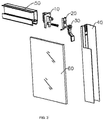
- a connecting device for connecting the horizontal track 50 and the vertical side frame 40 comprises a retaining member 10, a connecting member 20 and a locking member 30, wherein the retaining member may be mounted to the horizontal track 50 by a screw, the retaining member 10 and the locking member 30 may be hinged together by a pin.
- a rectangular chamber 55 is defined by a front wall 51, a rear wall 52, an upper wall 53 and a lower wall 54 of the horizontal track 50.
- a screw hole 56 is provided to be close to the lower wall 54.
- the front wall 51 is provided with a slide channel 57 along which the shower door 70 may slide.
- the lower wall 54 is provided with an installation channel 58 for installing the fixed glass panel 60, a door seal and the like.
- the vertical side frame 40 comprises a bottom wall 41 and two side walls 42 extending in a direction perpendicular with the bottom wall 41, so that an inner space 43 is defined by the bottom wall 41 and the two side walls.
- An intermediate portion of the bottom wall 41 is concaved toward the inner space 43 to form an installation channel 44 for installing the fixed glass panel 60, a door seal and the like.
- An end of the bottom wall 41 is provided with an opening 45 which is also disposed on a bottom wall of the installation channel 44.
- a locking hole 46 acting as a position-limiting structure is provided below the opening 45.
- the retaining member 10 comprises a retaining plate 11 provided with a lug 12 extending in a direction away from the horizontal track, a protrusion 13 with a cross section area slightly smaller than that of the chamber 55 is provided at an opposite side, so that the protrusion 13 can extend into the chamber 55 of the horizontal track 50, thereby helping to fix the retaining member 10.
- the lug 12 comprises a base part 16 and an extending part 18 which is provided with a hole 15.
- the retaining plate 11 is provided with a hole 14, so that the retaining member 10 can be fixed on an end face of the horizontal track 50 by a screw.
- a periphery of the retaining plate 11 is provided with a bent wall 17 extending towards the horizontal track 50, so that the end of the horizontal track 50 can be inserted into the bent wall 17, thereby protecting the end of the horizontal track and hiding a connection slit between the horizontal track and the retaining member.
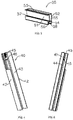
- the connecting member 20 includes a main body 21 and reinforcing plates 22 extending from the two sides of the main body 21 to reinforce the strength of the connecting member 20.
- the main body 21 is provided with an opening 23 from which the extending part 18 of the lug 12 may extend out.
- a hook 24 as a position-limiting structure is provided below the opening 23, and extends into the locking hole 46 of the vertical side frame 40 to restrict movement of the connecting member 20 in a direction perpendicular with the horizontal track.
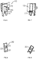
- the locking member 30 includes a connecting portion 32 to be hinged with the lug 12, a hand-held part 33 for applying with a force to rotate the locking member 30, and an intermediate part 31 between the connecting portion 32 and the hand-held part 33.
- the connecting portion 32 comprises an opening, and a width of the opening is basically identical with that of the extending part 18, so that the extending part 18 is clamped within the connecting portion 32.
- a hole 34 is provided to the connecting portion 32 at a position corresponding to the hole 15. Hinging between the connecting portion 32 and the lug 12 can be realized by a pin passing through the holes 34 and 15. That is, the locking member 30 can rotate around the central axes of the holes 34 and 15.
- the locking member 30 includes an arc part 35 and a projection 36.
- a distance L1 from the arc part 35 to the central axis of the hole 34 is smaller than a distance L2 from the projection 36 to the central axis of the hole 34.
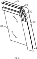
- FIG. 12-14 A process of connecting the horizontal track 50 and the vertical side frame 40 using the connecting device of this invention is shown in Figures 12-14 .
- the retaining member 10 may be fixed to an end of the horizontal track 50 by a screw in advance.
- the end of the horizontal track 50 extends into the bent wall 17, so that the extending part 18 of the lug 12 passes through the opening 23 of the connecting member 20 to form a protruding part protruding from the opening 23, and is hinged with the connecting portion 32 of the locking member 30.
- the arc part 35 of the connecting portion 32 of the locking member 30 faces the connecting member 20, the locking member 30 is in the unlocked position and may be generally parallel with the horizontal track 50.
- the fixed glass panel 60 may be installed in the installation channel 44 of the vertical side frame 40.
- the horizontal track 50 is moved towards the vertical side frame 40, so that the base part 16 of the lug 12 of the retaining member 10 enters into the installation channel 44 from an end of the vertical side frame 40.
- the connecting member 20 and the extending part 18 of the lug 12 enter into the inner space 43 of the vertical side frame 40 along the opening 45, and the reinforcing plates 22 of the connecting member 20 are positioned at outer sides of the two side walls of the installation channel 44.
- the locking member 30 is rotated to move towards the locked position.
- the projection 36 moves accordingly. When the projection 36 faces and presses against the connecting member 20, the connecting member 20 is pushed to abut against the bottom wall of the installation channel 44.
- the horizontal track 50 is pulled inversely to approach the vertical side frame 40, and the hook 24 of the connecting member 20 enters into the locking hole 46 of the vertical side frame 40.
- the locking member 30 is in the locked position, is basically perpendicular with the horizontal track 50 and is positioned within the inner space 43, thereby completing the connection between the horizontal track 50 and the vertical side frame 40. Therefore, the connection process is simple and convenient and does not need other auxiliary tools.
- the locking member 30 When detaching the horizontal track 50 from the vertical side frame 40, the locking member 30 is reversely rotated such that the arc part 35 of the locking member 30 faces the connecting member 20; the connecting member 20 may move until the hook 24 releases from the locking hole 46; then, the connecting device may move along the opening 45 and may be detached from the end of the vertical side frame 40. In such a way, the horizontal track can be detached from the vertical side frame easily and quickly without any auxiliary tools.
- connection between the retaining member and the horizontal track may realized by buckling or the like.
- the position-limiting structures of the connecting member and the vertical side frame may adopt other manners.
- the hinging manner between the locking member and the lug may be replaced by other known manners.
- the lug may have a hooked shape and may be hooked to a connecting rod inside the opening of the connecting portion.
- the shower door assembly of this invention is installed in a toilet, and acts as an important part of a shower room, which may be an integral shower room having a chassis or a shower room enclosed by the shower door assembly and walls with the shower door assembly installed between two adjacent walls with an included angle therebetween.
- the shower door assembly of this invention may only include an upper track or may include both upper and lower tracks.
- the shower door assembly of this invention is applicable for on-site assembling in customers' toilets.
- installation operations of the shower door assembly are simple.
- Relative fixing of the horizontal track and the vertical side frame can be realized by moving the locking member to the unlocked position to the locked position, which is simple and does not require other auxiliary tools. Therefore, assembling of the shower door assembly requires less time, thereby realizing quick and easy installation of the shower door assembly and reducing the manufacturing and assembling costs of the shower door assembly.
Landscapes
- Engineering & Computer Science (AREA)
- Civil Engineering (AREA)
- Structural Engineering (AREA)
- Health & Medical Sciences (AREA)
- Public Health (AREA)
- Epidemiology (AREA)
- General Health & Medical Sciences (AREA)
- Residential Or Office Buildings (AREA)
- Bathtubs, Showers, And Their Attachments (AREA)
Priority Applications (1)
| Application Number | Priority Date | Filing Date | Title |
|---|---|---|---|
| PL15860031T PL3085874T3 (pl) | 2015-01-28 | 2015-01-28 | Urządzenie połączeniowe i komponent drzwi prysznicowych zawierający to urządzenie |
Applications Claiming Priority (1)
| Application Number | Priority Date | Filing Date | Title |
|---|---|---|---|
| PCT/CN2015/071768 WO2016119149A1 (zh) | 2015-01-28 | 2015-01-28 | 连接装置及具有该连接装置的淋浴门组件 |
Publications (3)
| Publication Number | Publication Date |
|---|---|
| EP3085874A1 EP3085874A1 (en) | 2016-10-26 |
| EP3085874A4 EP3085874A4 (en) | 2016-12-28 |
| EP3085874B1 true EP3085874B1 (en) | 2017-10-04 |
Family
ID=56511968
Family Applications (1)
| Application Number | Title | Priority Date | Filing Date |
|---|---|---|---|
| EP15860031.2A Active EP3085874B1 (en) | 2015-01-28 | 2015-01-28 | Connection device and shower door component having same |
Country Status (7)
| Country | Link |
|---|---|
| US (1) | US9737175B2 (zh) |
| EP (1) | EP3085874B1 (zh) |
| CN (1) | CN106030014B (zh) |
| CA (1) | CA2931720C (zh) |
| ES (1) | ES2644412T3 (zh) |
| PL (1) | PL3085874T3 (zh) |
| WO (1) | WO2016119149A1 (zh) |
Cited By (1)
| Publication number | Priority date | Publication date | Assignee | Title |
|---|---|---|---|---|
| TWI841947B (zh) | 2021-04-26 | 2024-05-11 | 日商Ykk建築製造股份有限公司 | 連接結構以及門窗 |
Families Citing this family (7)
| Publication number | Priority date | Publication date | Assignee | Title |
|---|---|---|---|---|
| CN108601488B (zh) * | 2015-12-16 | 2021-05-07 | 阿罗玻璃镜业有限公司 | 淋浴围封间头 |
| CN106955049B (zh) * | 2017-05-24 | 2019-06-04 | 佛山市理想卫浴有限公司 | 一种淋浴门框架及淋浴门 |
| CN107956351A (zh) * | 2017-12-07 | 2018-04-24 | 平湖信达电子塑业有限公司 | 门玻导向件 |
| US11131140B2 (en) * | 2018-12-11 | 2021-09-28 | Arconic Technologies Llc | Corner joint clip with self-backing plate |
| US11873676B2 (en) * | 2019-01-30 | 2024-01-16 | Glass Technology | Pane unit and method used to produce and/or supply such a pane unit |
| WO2021056519A1 (zh) * | 2019-09-29 | 2021-04-01 | 平湖市贝诺维雅卫浴科技有限公司 | 一种快速安装锁紧机构 |
| CN114197989A (zh) * | 2021-12-22 | 2022-03-18 | 中山市福瑞卫浴设备有限公司 | 一种淋浴房 |
Family Cites Families (8)
| Publication number | Priority date | Publication date | Assignee | Title |
|---|---|---|---|---|
| DE19514402C1 (de) * | 1995-04-19 | 1996-06-20 | Rapid Maschbau Gmbh | Verfahren und Stanzmesser zur Herstellung einer Verbindung von Profilwerkstücken und Verbindungsstück |
| AUPN724995A0 (en) * | 1995-12-20 | 1996-01-18 | Allen House Mirror & Glass Pty Limited | A shower recess |
| US6701672B2 (en) * | 2001-04-30 | 2004-03-09 | Kohler Co. | Compression mounting system for shower doors |
| CN203175308U (zh) * | 2013-02-27 | 2013-09-04 | 佛山市爱迪尔卫浴有限公司 | 淋浴门安装结构 |
| CN203175265U (zh) * | 2013-03-05 | 2013-09-04 | 佛山市爱迪尔卫浴有限公司 | 淋浴门组件 |
| CN203175267U (zh) * | 2013-03-05 | 2013-09-04 | 佛山市爱迪尔卫浴有限公司 | 淋浴门组件 |
| CN203430290U (zh) * | 2013-06-03 | 2014-02-12 | 佛山市爱迪尔卫浴有限公司 | 门组件 |
| CN203394290U (zh) * | 2013-07-01 | 2014-01-15 | 李国超 | 一种用于淋浴房的滑轨和玻璃边框的连接结构 |
-
2015
- 2015-01-28 CA CA2931720A patent/CA2931720C/en active Active
- 2015-01-28 PL PL15860031T patent/PL3085874T3/pl unknown
- 2015-01-28 US US15/100,590 patent/US9737175B2/en active Active
- 2015-01-28 WO PCT/CN2015/071768 patent/WO2016119149A1/zh active Application Filing
- 2015-01-28 ES ES15860031.2T patent/ES2644412T3/es active Active
- 2015-01-28 EP EP15860031.2A patent/EP3085874B1/en active Active
- 2015-01-28 CN CN201580000046.6A patent/CN106030014B/zh active Active
Non-Patent Citations (1)
| Title |
|---|
| None * |
Cited By (1)
| Publication number | Priority date | Publication date | Assignee | Title |
|---|---|---|---|---|
| TWI841947B (zh) | 2021-04-26 | 2024-05-11 | 日商Ykk建築製造股份有限公司 | 連接結構以及門窗 |
Also Published As
| Publication number | Publication date |
|---|---|
| ES2644412T3 (es) | 2017-11-28 |
| EP3085874A1 (en) | 2016-10-26 |
| EP3085874A4 (en) | 2016-12-28 |
| CA2931720A1 (en) | 2016-07-28 |
| WO2016119149A1 (zh) | 2016-08-04 |
| CN106030014B (zh) | 2017-07-21 |
| PL3085874T3 (pl) | 2018-02-28 |
| CN106030014A (zh) | 2016-10-12 |
| US9737175B2 (en) | 2017-08-22 |
| US20160353939A1 (en) | 2016-12-08 |
| CA2931720C (en) | 2018-05-08 |
Similar Documents
| Publication | Publication Date | Title |
|---|---|---|
| EP3085874B1 (en) | Connection device and shower door component having same | |
| EP2774518B1 (en) | Shower door assembly | |
| US10709299B2 (en) | Shower door frame and shower door | |
| US20170152689A1 (en) | Adjustable door hinge | |
| CA2570091C (en) | Hinge attachment system and method | |
| EP3075939B1 (en) | Corner connection device of shower door track, shower door frame and shower door | |
| KR20170086088A (ko) | 창문 또는 도어용 슬라이딩 윙 또는 리프트-앤드-슬라이드 윙와 같은 슬라이딩 가능한 윙을 위한 씰링 장치 | |
| US10876332B2 (en) | Security device | |
| EP3061899B1 (en) | Shower door frame and shower door | |
| KR101085433B1 (ko) | 도어의 보조 잠금 장치 | |
| CA2841281A1 (en) | Door assembly | |
| US9790717B2 (en) | Door security reinforcement system | |
| KR102442876B1 (ko) | 전기 외장용 폐쇄 장치, 및 그에 상응하는 전기 외장 | |
| EP2937496B1 (en) | Operating handle for a folding/sliding door | |
| KR102464988B1 (ko) | 창문용 추락방지장치 | |
| US9388611B2 (en) | Multi-point lock having a flush-mount cylinder | |
| EP1746921B1 (en) | Hinge | |
| KR200465279Y1 (ko) | 샤워 부스용 도어 어셈블리 | |
| JP6386617B2 (ja) | トイレブースのパネル体取り付け構造 | |
| JP5570885B2 (ja) | ドア装置のリフォームにおけるドア枠構造 | |
| KR102026443B1 (ko) | 창호용 잠금핸들의 설치구조 | |
| KR200373361Y1 (ko) | 천장 점검구의 개폐장치 | |
| EP3067503B1 (en) | Shower door system, and assembly therefor | |
| GB2441453B (en) | Locks for windows and doors | |
| KR200351050Y1 (ko) | 방화문용 안전록 |
Legal Events
| Date | Code | Title | Description |
|---|---|---|---|
| PUAI | Public reference made under article 153(3) epc to a published international application that has entered the european phase |
Free format text: ORIGINAL CODE: 0009012 |
|
| 17P | Request for examination filed |
Effective date: 20160525 |
|
| AK | Designated contracting states |
Kind code of ref document: A1 Designated state(s): AL AT BE BG CH CY CZ DE DK EE ES FI FR GB GR HR HU IE IS IT LI LT LU LV MC MK MT NL NO PL PT RO RS SE SI SK SM TR |
|
| AX | Request for extension of the european patent |
Extension state: BA ME |
|
| STAA | Information on the status of an ep patent application or granted ep patent |
Free format text: STATUS: EXAMINATION IS IN PROGRESS |
|
| A4 | Supplementary search report drawn up and despatched |
Effective date: 20161128 |
|
| RIC1 | Information provided on ipc code assigned before grant |
Ipc: A47K 3/34 20060101ALI20161122BHEP Ipc: E06B 3/46 20060101ALI20161122BHEP Ipc: E06B 3/964 20060101AFI20161122BHEP |
|
| 17Q | First examination report despatched |
Effective date: 20161213 |
|
| GRAP | Despatch of communication of intention to grant a patent |
Free format text: ORIGINAL CODE: EPIDOSNIGR1 |
|
| STAA | Information on the status of an ep patent application or granted ep patent |
Free format text: STATUS: GRANT OF PATENT IS INTENDED |
|
| INTG | Intention to grant announced |
Effective date: 20170524 |
|
| GRAA | (expected) grant |
Free format text: ORIGINAL CODE: 0009210 |
|
| GRAS | Grant fee paid |
Free format text: ORIGINAL CODE: EPIDOSNIGR3 |
|
| STAA | Information on the status of an ep patent application or granted ep patent |
Free format text: STATUS: THE PATENT HAS BEEN GRANTED |
|
| AK | Designated contracting states |
Kind code of ref document: B1 Designated state(s): AL AT BE BG CH CY CZ DE DK EE ES FI FR GB GR HR HU IE IS IT LI LT LU LV MC MK MT NL NO PL PT RO RS SE SI SK SM TR |
|
| DAX | Request for extension of the european patent (deleted) | ||
| REG | Reference to a national code |
Ref country code: GB Ref legal event code: FG4D |
|
| REG | Reference to a national code |
Ref country code: CH Ref legal event code: EP |
|
| REG | Reference to a national code |
Ref country code: AT Ref legal event code: REF Ref document number: 934226 Country of ref document: AT Kind code of ref document: T Effective date: 20171015 |
|
| REG | Reference to a national code |
Ref country code: IE Ref legal event code: FG4D |
|
| REG | Reference to a national code |
Ref country code: DE Ref legal event code: R096 Ref document number: 602015005206 Country of ref document: DE |
|
| REG | Reference to a national code |
Ref country code: ES Ref legal event code: FG2A Ref document number: 2644412 Country of ref document: ES Kind code of ref document: T3 Effective date: 20171128 |
|
| REG | Reference to a national code |
Ref country code: FR Ref legal event code: PLFP Year of fee payment: 4 |
|
| REG | Reference to a national code |
Ref country code: NL Ref legal event code: MP Effective date: 20171004 |
|
| REG | Reference to a national code |
Ref country code: LT Ref legal event code: MG4D |
|
| REG | Reference to a national code |
Ref country code: AT Ref legal event code: MK05 Ref document number: 934226 Country of ref document: AT Kind code of ref document: T Effective date: 20171004 |
|
| PG25 | Lapsed in a contracting state [announced via postgrant information from national office to epo] |
Ref country code: NL Free format text: LAPSE BECAUSE OF FAILURE TO SUBMIT A TRANSLATION OF THE DESCRIPTION OR TO PAY THE FEE WITHIN THE PRESCRIBED TIME-LIMIT Effective date: 20171004 |
|
| PG25 | Lapsed in a contracting state [announced via postgrant information from national office to epo] |
Ref country code: NO Free format text: LAPSE BECAUSE OF FAILURE TO SUBMIT A TRANSLATION OF THE DESCRIPTION OR TO PAY THE FEE WITHIN THE PRESCRIBED TIME-LIMIT Effective date: 20180104 Ref country code: SE Free format text: LAPSE BECAUSE OF FAILURE TO SUBMIT A TRANSLATION OF THE DESCRIPTION OR TO PAY THE FEE WITHIN THE PRESCRIBED TIME-LIMIT Effective date: 20171004 Ref country code: FI Free format text: LAPSE BECAUSE OF FAILURE TO SUBMIT A TRANSLATION OF THE DESCRIPTION OR TO PAY THE FEE WITHIN THE PRESCRIBED TIME-LIMIT Effective date: 20171004 Ref country code: LT Free format text: LAPSE BECAUSE OF FAILURE TO SUBMIT A TRANSLATION OF THE DESCRIPTION OR TO PAY THE FEE WITHIN THE PRESCRIBED TIME-LIMIT Effective date: 20171004 |
|
| PG25 | Lapsed in a contracting state [announced via postgrant information from national office to epo] |
Ref country code: RS Free format text: LAPSE BECAUSE OF FAILURE TO SUBMIT A TRANSLATION OF THE DESCRIPTION OR TO PAY THE FEE WITHIN THE PRESCRIBED TIME-LIMIT Effective date: 20171004 Ref country code: BG Free format text: LAPSE BECAUSE OF FAILURE TO SUBMIT A TRANSLATION OF THE DESCRIPTION OR TO PAY THE FEE WITHIN THE PRESCRIBED TIME-LIMIT Effective date: 20180104 Ref country code: AT Free format text: LAPSE BECAUSE OF FAILURE TO SUBMIT A TRANSLATION OF THE DESCRIPTION OR TO PAY THE FEE WITHIN THE PRESCRIBED TIME-LIMIT Effective date: 20171004 Ref country code: IS Free format text: LAPSE BECAUSE OF FAILURE TO SUBMIT A TRANSLATION OF THE DESCRIPTION OR TO PAY THE FEE WITHIN THE PRESCRIBED TIME-LIMIT Effective date: 20180204 Ref country code: GR Free format text: LAPSE BECAUSE OF FAILURE TO SUBMIT A TRANSLATION OF THE DESCRIPTION OR TO PAY THE FEE WITHIN THE PRESCRIBED TIME-LIMIT Effective date: 20180105 Ref country code: HR Free format text: LAPSE BECAUSE OF FAILURE TO SUBMIT A TRANSLATION OF THE DESCRIPTION OR TO PAY THE FEE WITHIN THE PRESCRIBED TIME-LIMIT Effective date: 20171004 Ref country code: LV Free format text: LAPSE BECAUSE OF FAILURE TO SUBMIT A TRANSLATION OF THE DESCRIPTION OR TO PAY THE FEE WITHIN THE PRESCRIBED TIME-LIMIT Effective date: 20171004 |
|
| REG | Reference to a national code |
Ref country code: DE Ref legal event code: R097 Ref document number: 602015005206 Country of ref document: DE |
|
| PG25 | Lapsed in a contracting state [announced via postgrant information from national office to epo] |
Ref country code: SK Free format text: LAPSE BECAUSE OF FAILURE TO SUBMIT A TRANSLATION OF THE DESCRIPTION OR TO PAY THE FEE WITHIN THE PRESCRIBED TIME-LIMIT Effective date: 20171004 Ref country code: DK Free format text: LAPSE BECAUSE OF FAILURE TO SUBMIT A TRANSLATION OF THE DESCRIPTION OR TO PAY THE FEE WITHIN THE PRESCRIBED TIME-LIMIT Effective date: 20171004 Ref country code: EE Free format text: LAPSE BECAUSE OF FAILURE TO SUBMIT A TRANSLATION OF THE DESCRIPTION OR TO PAY THE FEE WITHIN THE PRESCRIBED TIME-LIMIT Effective date: 20171004 |
|
| PLBE | No opposition filed within time limit |
Free format text: ORIGINAL CODE: 0009261 |
|
| STAA | Information on the status of an ep patent application or granted ep patent |
Free format text: STATUS: NO OPPOSITION FILED WITHIN TIME LIMIT |
|
| PG25 | Lapsed in a contracting state [announced via postgrant information from national office to epo] |
Ref country code: RO Free format text: LAPSE BECAUSE OF FAILURE TO SUBMIT A TRANSLATION OF THE DESCRIPTION OR TO PAY THE FEE WITHIN THE PRESCRIBED TIME-LIMIT Effective date: 20171004 Ref country code: SM Free format text: LAPSE BECAUSE OF FAILURE TO SUBMIT A TRANSLATION OF THE DESCRIPTION OR TO PAY THE FEE WITHIN THE PRESCRIBED TIME-LIMIT Effective date: 20171004 |
|
| REG | Reference to a national code |
Ref country code: CH Ref legal event code: PL |
|
| 26N | No opposition filed |
Effective date: 20180705 |
|
| PG25 | Lapsed in a contracting state [announced via postgrant information from national office to epo] |
Ref country code: LU Free format text: LAPSE BECAUSE OF NON-PAYMENT OF DUE FEES Effective date: 20180128 |
|
| REG | Reference to a national code |
Ref country code: IE Ref legal event code: MM4A |
|
| REG | Reference to a national code |
Ref country code: BE Ref legal event code: MM Effective date: 20180131 |
|
| PG25 | Lapsed in a contracting state [announced via postgrant information from national office to epo] |
Ref country code: BE Free format text: LAPSE BECAUSE OF NON-PAYMENT OF DUE FEES Effective date: 20180131 Ref country code: CH Free format text: LAPSE BECAUSE OF NON-PAYMENT OF DUE FEES Effective date: 20180131 Ref country code: SI Free format text: LAPSE BECAUSE OF FAILURE TO SUBMIT A TRANSLATION OF THE DESCRIPTION OR TO PAY THE FEE WITHIN THE PRESCRIBED TIME-LIMIT Effective date: 20171004 Ref country code: LI Free format text: LAPSE BECAUSE OF NON-PAYMENT OF DUE FEES Effective date: 20180131 |
|
| PG25 | Lapsed in a contracting state [announced via postgrant information from national office to epo] |
Ref country code: IE Free format text: LAPSE BECAUSE OF NON-PAYMENT OF DUE FEES Effective date: 20180128 |
|
| PG25 | Lapsed in a contracting state [announced via postgrant information from national office to epo] |
Ref country code: MC Free format text: LAPSE BECAUSE OF FAILURE TO SUBMIT A TRANSLATION OF THE DESCRIPTION OR TO PAY THE FEE WITHIN THE PRESCRIBED TIME-LIMIT Effective date: 20171004 |
|
| PG25 | Lapsed in a contracting state [announced via postgrant information from national office to epo] |
Ref country code: MT Free format text: LAPSE BECAUSE OF NON-PAYMENT OF DUE FEES Effective date: 20180128 |
|
| PG25 | Lapsed in a contracting state [announced via postgrant information from national office to epo] |
Ref country code: TR Free format text: LAPSE BECAUSE OF FAILURE TO SUBMIT A TRANSLATION OF THE DESCRIPTION OR TO PAY THE FEE WITHIN THE PRESCRIBED TIME-LIMIT Effective date: 20171004 |
|
| PG25 | Lapsed in a contracting state [announced via postgrant information from national office to epo] |
Ref country code: PT Free format text: LAPSE BECAUSE OF FAILURE TO SUBMIT A TRANSLATION OF THE DESCRIPTION OR TO PAY THE FEE WITHIN THE PRESCRIBED TIME-LIMIT Effective date: 20171004 |
|
| PG25 | Lapsed in a contracting state [announced via postgrant information from national office to epo] |
Ref country code: HU Free format text: LAPSE BECAUSE OF FAILURE TO SUBMIT A TRANSLATION OF THE DESCRIPTION OR TO PAY THE FEE WITHIN THE PRESCRIBED TIME-LIMIT; INVALID AB INITIO Effective date: 20150128 Ref country code: MK Free format text: LAPSE BECAUSE OF NON-PAYMENT OF DUE FEES Effective date: 20171004 Ref country code: CY Free format text: LAPSE BECAUSE OF FAILURE TO SUBMIT A TRANSLATION OF THE DESCRIPTION OR TO PAY THE FEE WITHIN THE PRESCRIBED TIME-LIMIT Effective date: 20171004 |
|
| PG25 | Lapsed in a contracting state [announced via postgrant information from national office to epo] |
Ref country code: AL Free format text: LAPSE BECAUSE OF FAILURE TO SUBMIT A TRANSLATION OF THE DESCRIPTION OR TO PAY THE FEE WITHIN THE PRESCRIBED TIME-LIMIT Effective date: 20171004 |
|
| PGFP | Annual fee paid to national office [announced via postgrant information from national office to epo] |
Ref country code: DE Payment date: 20220119 Year of fee payment: 8 |
|
| PGFP | Annual fee paid to national office [announced via postgrant information from national office to epo] |
Ref country code: PL Payment date: 20220120 Year of fee payment: 8 Ref country code: IT Payment date: 20220120 Year of fee payment: 8 Ref country code: CZ Payment date: 20220121 Year of fee payment: 8 |
|
| PGFP | Annual fee paid to national office [announced via postgrant information from national office to epo] |
Ref country code: FR Payment date: 20230123 Year of fee payment: 9 |
|
| REG | Reference to a national code |
Ref country code: DE Ref legal event code: R119 Ref document number: 602015005206 Country of ref document: DE |
|
| PG25 | Lapsed in a contracting state [announced via postgrant information from national office to epo] |
Ref country code: DE Free format text: LAPSE BECAUSE OF NON-PAYMENT OF DUE FEES Effective date: 20230801 Ref country code: CZ Free format text: LAPSE BECAUSE OF NON-PAYMENT OF DUE FEES Effective date: 20230128 |
|
| PG25 | Lapsed in a contracting state [announced via postgrant information from national office to epo] |
Ref country code: IT Free format text: LAPSE BECAUSE OF NON-PAYMENT OF DUE FEES Effective date: 20230128 |
|
| PGFP | Annual fee paid to national office [announced via postgrant information from national office to epo] |
Ref country code: ES Payment date: 20240206 Year of fee payment: 10 |
|
| PGFP | Annual fee paid to national office [announced via postgrant information from national office to epo] |
Ref country code: GB Payment date: 20240129 Year of fee payment: 10 |