EP3085859A1 - Variable lock cylinder - Google Patents
Variable lock cylinder Download PDFInfo
- Publication number
- EP3085859A1 EP3085859A1 EP16166547.6A EP16166547A EP3085859A1 EP 3085859 A1 EP3085859 A1 EP 3085859A1 EP 16166547 A EP16166547 A EP 16166547A EP 3085859 A1 EP3085859 A1 EP 3085859A1
- Authority
- EP
- European Patent Office
- Prior art keywords
- module
- connecting element
- cylinder body
- modules
- head part
- Prior art date
- Legal status (The legal status is an assumption and is not a legal conclusion. Google has not performed a legal analysis and makes no representation as to the accuracy of the status listed.)
- Granted
Links
Images


Classifications
-
- E—FIXED CONSTRUCTIONS
- E05—LOCKS; KEYS; WINDOW OR DOOR FITTINGS; SAFES
- E05B—LOCKS; ACCESSORIES THEREFOR; HANDCUFFS
- E05B9/00—Lock casings or latch-mechanism casings ; Fastening locks or fasteners or parts thereof to the wing
- E05B9/04—Casings of cylinder locks
- E05B9/045—Modular casings for adjusting the length of cylinder locks
-
- E—FIXED CONSTRUCTIONS
- E05—LOCKS; KEYS; WINDOW OR DOOR FITTINGS; SAFES
- E05B—LOCKS; ACCESSORIES THEREFOR; HANDCUFFS
- E05B15/00—Other details of locks; Parts for engagement by bolts of fastening devices
- E05B15/04—Spring arrangements in locks
- E05B2015/0458—Leaf springs; Non-wound wire springs
Definitions
- the invention relates to an extendable lock cylinder, in particular an extendable cylinder body for electronic locking systems such as electronic lock cylinder. More particularly, the invention relates to extendible cylinder bodies for electronic double knob cylinders or single knob cylinders.
- mortise locks are provided according to DIN 18251 for doors with mechanical locking cylinders according to DIN 18252.
- Such lock cylinders have a cylinder housing and therein a cylinder core, which can be rotated with a matching key in the housing and moves out of the cylinder housing cam (driver) moves to unlock or lock the lock.
- cam driver
- the lock cylinder is today the heart of the security of lock and door.
- Electronic lock cylinders are also known in the prior art.
- Electronic lock cylinders are generally characterized by the fact that instead of the mechanical coding of the key an electronic coding, e.g. is used in the form of electrical signals.
- an "electronic key” is used in the form of a transmitter or transponder, which transmits electrical signals by means of electromagnetic waves from the transponder or transmitter to the lock cylinder.
- the signals are verified by means of an electronic device, the electronic device usually being housed in a knob or in two knobs provided on the lock cylinder or profile cylinder.
- the knob or the knobs are preferably used in addition to the accommodation of electronic components as a handle for actuating the lock cylinder and its cam.
- the length of the built-in lock cylinder should preferably correspond to the respective door thickness (door leaf), since the cylinders should not protrude for safety reasons and for aesthetic reasons as possible over the door leaf or the door fitting or be mounted too deep inside the door.
- the length of the cylinder body is also dependent on the thickness of the door fitting. For example, a lock cylinder that is too short can not be fitted if a wider door fitting is used.
- lock cylinders with different lengths are therefore offered on the market.
- mechanical lock cylinders are offered, which are sold in a few mm increments to the different door thicknesses.
- Each special lock cylinder is then used only for a certain door thickness. This has the consequence that finished lock cylinders of different lengths must be produced and stocked in the warehouse, but this leads to high manufacturing and storage costs.
- an elongated cylinder body which consists of modules which have mutual guides and which are axially screwed together.
- the cylinder body consists of a center module and two outside termination modules. On either side of the center module as many extension modules can be screwed.
- a disadvantage of this solution is the fact that a screw for connecting the modules must be screwed in axially, with a screwing in the axial direction having disadvantages in terms of ease of assembly is associated.
- a corresponding disadvantage manifests itself in disassembly and reassembly of the cylinder body; here It takes quite a bit of getting used to processes that are not self-evident to the end user.
- An advantage of the present invention is, for example, in the simple or very simple installation, so that the cylinder body can be extended by an end user / user without expertise even or can be shortened again.
- the invention relates to profile cylinder wherein the axial direction along the length of the cylinder extends.
- the overall length is the length of a cylinder, measured from the center of its closing lug (usually also the center of the forend screw thread) to the respective closing side.
- the overall length of a double cylinder basically consists of the dimensions of both sides, while the overall length of a half cylinder consists of a dimension.
- a variable cylinder body is provided, preferably for electronic locking systems, in particular for electronic lock cylinders.
- the cylinder body has a central module and at least one outer-side termination module and / or an inner-side termination module.
- the cam is preferably rotatably arranged in the central module.
- one, preferably two, three, four or any number of extension modules can be inserted between the center module and the outer terminating module and / or between the center module and the inner terminator, in order to individually adjust the overall length of the cylinder body but also the length outwards or inwards.
- the inside end module is connected to the center module and by an axially arranged fastening bolt.
- the outer-side termination module is connected to the center module and by an axially arranged fastening bolt.
- the extension module or the extension modules are preferably clamped between the center module and the termination module. In other words, it is preferably sufficient if the connecting element bwz.
- the mounting bolt engages the center module and the termination module so that a tensile stress is built up between them.
- a foot part of the fastening bolt with a first module is fixed (preferably fixed in the pulling direction), for example, the center module or the termination module.
- a head part of the fastening bolt with the second module is firmly connected, for example, the termination module or the center module.
- This second connection is made by an inserted into the entprechende module or pressed Verspannelement, which is inserted radially inserted into the corresponding module with inserted clamping element and with the head part of the fastening bolt engages so that a tension of the fastening bolt is made in the axial direction.
- the length of the fastening bolt is preferably adapted to the length of the extension module and preferably also to the termination module.
- the fastening bolt is arranged in the axial direction, which means the term of the length of the fastening bolt as well as the modules in the axial direction.
- the fastening bolt can either have a round profile (cut perpendicular to the length) or have a rectangular profile.
- the profile can also change over the length, that is, the cross section of the bolt need not be the same over the entire length of the fastening bolt, which can offer significant advantages in terms of assembly.
- a preferred and decisive advantage of the present invention lies in the design of the bracing element, which preferably leads to a fixation of the system by simply inserting or inserting into a corresponding slot in a module.
- the simple insertion allows a simple yet secure installation.
- the bracing element can be easily and yet accurately produced.
- the clamping element can be produced by pressing and / or punching, whereby a simple and even cost-effective production method can be used while maintaining the desired tolerances.
- the invention relates to a variable cylinder body for electronic locking systems, in particular for electronic lock cylinders, wherein the cylinder body has a central module and at least one outer-side termination module and / or an inner-side termination module. Between the center module and the outer side termination module and / or between the middle module and the inside termination module, any number of extension modules can be inserted according to the invention. For example, one, two, three, four or five extension modules may be employed therebetween. Preferably, it is also possible that a termination module directly on the center module can be attached, ie, it is used no extension module in between. In addition, a person skilled in the art will recognize that a different number and also modules of different lengths (measured in the axial direction) can be used on the inside and outside.
- a first of the modules is fixedly connected to one another by an axially arranged connecting element with a second of the modules.
- the connector may be a mounting bolt, as discussed in greater detail below.
- the connecting element or the fastening bolt is not screwed, which is particularly preferred in view of a simple assembly.
- the connecting element preferably has two ends with respect to the longitudinal extent, wherein one end should be referred to as a foot part and the other end as a head part.
- the connecting element is connected for mounting with the first module, preferably in an axial pulling direction. This connection need not be fixed during assembly, that is, axial displacement is possible. However, if the cylinder body is finally mounted, then a tensile stress between the middle module and termination module is made by the connecting element, so that these two modules and preferably also arranged therebetween extension modules are firmly pressed against each other, or are firmly mounted together.
- the head part of the connecting element or of the fastening bolt in the second module is axially movably inserted during assembly and by a radially inserted into the second module Verspannelement which acts against the head part, or with the head part is engaged , strained or fastened.
- inserted clamping element prevents an axial pulling apart of the two connected modules and preferably generates an axially directed tensile force, which presses the two connected modules against each other.
- the clamping element is inserted or pressed in and is not screwed in. This facilitates on the one hand the assembly and disassembly and preferably prevents incorrect assembly.
- the foot part of the connecting element is connected to the central module, preferably firmly connected.
- the radially inserted clamping element is accordingly preferably inserted in the inside end module or the outside end module in order to fix the head part of the connecting element (or fastening bolt) in an axial direction.
- a tensile stress is built up by the connecting element in cooperation with the bracing element which acts against the head part in the pulling direction (axially), that this tensile stress is built up in the connecting element and a corresponding force presses the head part and any extension modules against the center module.
- the foot part of the connecting element is connected to the inside end module or outside end module, preferably firmly connected.
- the radially inserted clamping element is accordingly preferably inserted in the central module in order to fix the head part of the connecting element (or fastening bolt) in an axial direction.
- the connecting element is preferably designed as a fastening bolt.
- the connecting element has a rectangular profile.
- the connecting element is formed from a plurality of layers of material, wherein preferably each of the layers is formed by stamping and / or compression molding.
- the biasing member preferably has a recess at a first end for engaging the head portion of the connector to provide the tensile force.
- the bracing element has, preferably and at a second end, an opening into which, for example, an assembly tool, for example a rod for assembly or disassembly, can be inserted.
- the bracing element is inserted radially. This can also be done, for example, by hand or with the aid of a hammer.
- the bracing element is preferably constructed so that it braces itself in the closure module. This is achieved, for example, in that the bracing element is configured at an angle and braced in the corresponding straight-shaped slot in the end module of the cylinder body. In order to achieve a simple disassembly of this Verspannelements, the Verspannelement can be levered out or pulled out again, for example, with the mounting tool or the rod.
- the bracing member consists essentially of a plate-shaped member which is preferably bent at a second end out of the plane of the plate-shaped member to clamp in a straight slot in one of the modules of the cylinder body.
- the foot part of the connecting element is preferably screwed loosely into the center module.
- the tensile stress is used to clamp the modules preferably not achieved by a screw, but by the introduction of the Verspannelements.
- the foot part of the connecting element has a hook part to be connected to the center module by hooking.
- the connecting element on the foot part on a circumferential recess or circumferential groove, wherein in this recess or groove a clamping ring can be used.
- the bracing element can preferably be produced very easily.
- the bracing element may be a flat part, preferably produced by pressing and / or punching.
- an extension module with a desired axial extent is arranged next to the center module, so that the connection element extends through the extension module in the axial direction.
- the termination module next to the extension module can be arranged so that the head part of the connecting element in the axial direction in the termination module inside extends.
- the modules are still displaceable in the axial direction.
- the bracing element is then inserted or pressed radially into the termination module. The bracing member thereby engages the head portion of the extension module so that tension is developed in the connector and a corresponding force is generated by pressing the termination module and the extension module against the center module.
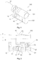
- FIG. 1 shows in a perspective view a part of an inventive expandable cylinder body 100, wherein the cylinder body of the illustrated profile cylinder has a cylindrical or round core portion 101 and the flange portion 102.
- the cylinder body according to the invention can be used for mechanical lock cylinder, but is preferably used for electronic lock cylinder.
- FIG. 1 only one door outer side end module 20, wherein for simplicity a corresponding inside end module 30 is not shown. It will be apparent, however, to one skilled in the art, that the following statements with respect to the outboard termination module 20 with the corresponding extension modules 40 are respectively applicable to an inboard termination module 30.
- the position of a corresponding inside end module 30 is shown symbolically only by the curly bracket. However, this does not mean that the outside end module 20 has to be constructed exactly the same as the inside end module 30. For example, different security requirements with regard to the two end modules 30 may be desired or necessary. So on the outside a Bohrschutz be desired, whereas on the inside can be dispensed with a Bohrschutz.
- termination modules 20, 30 in general, which can be mounted substantially identical or exactly identical both on the inside and on the outside of the door , This has the advantage, for example, that a smaller number of different end modules must be produced, which results in lower production costs and lower storage costs.
- the inside modules are preferably made the same as the outside modules and are preferably assembled in the same way as the outside modules.
- FIG. 1 shows the center module 10 with the forend screw hole 11, which serves to fasten the cylinder 100 by means of forend screw in the door leaf or in the lock case.
- the center module 10 shown is simplified, ie without the driver (often referred to as a closing nose or cam) is to be arranged in the recess shown in order to operate the lock.
- the extension module 40 is inserted between middle module 10 and outer end module 20, the extension module 40 is inserted.
- FIG. 2 shows one to FIG. 1 corresponding cross-sectional view, it can be seen that the cylindrical part (the core portion 101) of the center module 10, the cylindrical part of the outer side end module 20 and the cylindrical part of the extension module 40 have guides 90 to a precise alignment to ensure each other and to prevent displacement in the radial direction or prevent. Additionally or alternatively, guides may also be present in the flange section in order to prevent a lateral displacement of the individual modules.
- the axial direction A and radial direction R is in Fig. 2 shown.
- a connecting element or fastening bolt 50 in the form of a screw with foot part 51 and head part 52, with which the three modules 10, 40, 20 shown are connected to one another.
- the fastening bolt may be a commercially available screw.
- head shapes for the head part 52 are possible, for example, a hexagonal head, a cylinder head or a round head.
- the three modules are interconnected according to a preferred embodiment as follows.
- the extension module 40 is placed on the center module 10, wherein the above-mentioned guides 90 in the cylindrical part help to properly align the modules with each other; a shift in the radial direction is avoided or prevented.
- the fastening bolt 50 is performed by the extension module 40 or a corresponding recess 41 or bore in the extension module 40 and the foot part 51 of the fastening bolt 50 attached to the center module 10.
- the foot part 51 of the fastening bolt 50 is simply screwed into a corresponding bore in the central module 10.
- the hole in the middle module may be, for example, a through hole (as shown) or a blind hole.
- the outer side termination module 20 in which a recess 21 is provided, is slid with this recess 21 over the head portion 52 of the fastening bolt.
- the guide 90 in the cylindrical part of the end module 20 helps to properly locate the modules in the axial direction.
- the Recess 21 be formed as a blind hole in the radial direction in the flange 102.
- the head portion 52 of the fastening bolt 50 within the recess 21 of the outer end module 20 in the axial direction A has a small clearance, which in FIG. 2 represented by the reference numeral 22.
- the bracing member 53 is radially inserted from below into the recess 23 formed in the flange portion 102 of the outer side end module 20, so that the bracing member engages with the head portion 52 of the fastening bolt 50 and axially displaces the modules 10, 40 and 20 prevented.
- the outside is completely assembled.
- a decisive advantage of the present invention is that after merging the modules, the attachment is achieved very simply by only one clamping element 53 is inserted / inserted radially into the outer side termination module 20.
- the assembly is very easy.
- an end user recognizes the correct assembly because the clamping element 53 is preferably inserted flush with the underside of the flange portion 102 of the end module. This can be ensured in a simple manner that the modules are connected correctly by an end user.
- Known screw solutions often have the disadvantage that a correct installation can be dependent on the torques with which the screws are screwed. If, for example, a screw with too high a torque is screwed in, then this screw is in a too "deep" position.
- the embodiment of a threaded fastening bolt 50 on the foot part 51 has advantages in terms of manufacturing costs.
- a disadvantage of this solution is that the depth of engagement of the fastening bolt 50 in the center module 10 may possibly vary slightly, depending on the torque with which the end user screws the fastening bolt 50 into the central module 10. According to the invention, this uncertainty can be further reduced in that the thread on the foot part 51 has a stop which prevents the fastening bolt from being screwed too far into the center module 10.
- FIG. 5 shows, for example, a fastening bolt 50 with a head portion 52 similar to the embodiment of FIG. 2 .
- the embodiment of the Fig. 5 shows a foot 51, similar to the head 52nd is trained. Both the head part and the foot part are formed substantially T-shaped.
- the foot part 51 of the fastening bolt 50 is connected to the central module 10.
- the center module 10 may for example have an opening 11 in the form of a slot.
- the slot 11 may have the longer extent in the radial direction, here from top to bottom.
- the T-shaped head part 51 can thus be performed through the slot 11, and then rotated by 90 °, so that the foot part 51 in the rotated position no longer fits through the slot 11 and the head part under tensile load with the center module 10 engages ,
- the extension module 40 to be arranged therebetween is preferably also formed with a corresponding oblong hole.
- a larger hole or a larger opening 41 is formed in the extension module 40, since a direct attachment between the fastening bolt 50 and extension module 40 preferably does not occur.
- the extension module 40 is preferably clamped only between the center module and an outside or inside termination module.
- the fastening bolt 50 can be performed by the extension module 40, without coming into direct engagement with the extension module 40 itself.
- the fastening bolt 50 may also be waisted and have a waist portion 55 which may preferably serve to rotate the fastening bolt in the slot 11 by 90 °.
- FIG. 3 an embodiment of a clamping element 53 according to the invention is shown, which preferably has the shape of a plate or a small plate.
- This simple, platelet-shaped embodiment again has the advantage, for example, that the simple and known production method can be used which, in addition, is cost-effective while maintaining a high degree of precision in terms of dimensions.
- FIG. 5 shows a similar view, but the bolt 50 already arranged in the center module 10.
- FIG. 4 shows similar to the FIG. 1 a perspective view of a portion of the cylinder head 100, wherein the extension module 40 between the center module 10 and the termination module 30 is arranged. Similar in the FIG. 3 can be seen in the center module 10 of the fastening bolts 50, in particular the foot part 51.
- the closure module 20 in the flange portion 110, the recess 23 is shown, into which the clamping element 53 is inserted (shown in FIG FIG. 4 by the double arrow).
- the bracing member 53 preferably has two sections, the first section 531 having a recess for engaging the fastening bolt 50 and for securing the fastening bolt 50 in the axial direction.
- the second portion 532 is preferably for inserting or removing the clamp member 53.
- the second portion 532 is shown unwound from the first portion 531, thereby providing tensioning of the tension member 53 within the slot 23.
- a round opening 533 is shown on the second section, which can serve, for example, to simply remove the bracing element 53.
- a round rod (not shown) is inserted into the opening 533 and levered out of the inserted position by means of leverage.
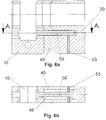
- FIG. 6a and 6b show the position of the connecting element 50 according to the invention according to FIG. 5 in two different mutually perpendicular cross-sectional views in the clamped state in the cylinder body.
- FIG. 6a corresponds to an outline
- Fig. 6b corresponds to a floor plan.
- Both the head part and the foot part are formed substantially T-shaped, wherein both T-shaped heads are formed in the same plane.
- the fastening bolt 50 is correspondingly flat in one plane (see Fig. 6a ) and the T-shaped heads are only in the Fig. 6b visible, noticeable.
- fastening bolts should be formed with a rectangular cross-section, ie, rectangular, if one were to cut the fastening bolt along a plane perpendicular to the axial longitudinal extent of the bolt.
- This rectangular cross-section can be made simpler, in contrast to round embodiments, for example by pressing or punching.
- the foot part 51 of the fastening bolt 50 is connected to the central module 10.
- the T-shaped head part 51 can be performed by a corresponding elongated opening 11, and then rotated by 90 °, so that the foot part 51 can not be pulled out in the rotated position through the slot 11, the head part comes under tensile load the center module 10 in engagement.
- the extension module 40 to be arranged therebetween is preferably also formed with a corresponding oblong hole.
- a larger hole or opening 41 is formed in the extension module 40, since a direct attachment between the fastening bolt 50 and extension module 40 preferably does not occur. This is, for example, through the gap 49 in FIG Fig.
- the fastening bolt 50 may also be waisted and have a waist portion 55 which may preferably serve to rotate the fastening bolt in the slot 11 by 90 °.
- the invention also includes the exact or exact terms, features, numerical values or ranges, etc. when, above or below, these terms, features, numerical values or ranges are used in conjunction with terms such as, for example. "about, about, essentially, in general, at least, at least”, etc., were called (ie, “about 3” should also “3” or “substantially radially” should also include “radial”).
- the expression “or” means moreover “and / or”.
Abstract
Die vorliegende Erfindung betrifft einen veränderbaren Zylinderkörper (100) für elektronische Schließsysteme, insbesondere für elektronische Schließzylinder, wobei der Zylinderkörper aufweist: ein Mittelmodul (10) und zumindest ein außenseitiges Abschlussmodul (20) und/oder ein innenseitiges Abschlussmodul (30), wobei zwischen Mittelmodul (10) und außenseitigem Abschlussmodul (20) und/oder zwischen Mittelmodul (10) und innenseitigem Abschlussmodul (30) beliebig viele Verlängerungsmodule (40) eingefügt werden können. Ein erstes der Module (10, 20, 30, 40) kann durch ein axial angeordnetes Verbindungselement (50) mit einem zweiten der Module (10, 20, 30, 40) fest verbunden werden, wobei ein Fußteil (51) des Verbindungselements (50) mit dem ersten Modul in axialer Zugrichtung fest verbunden ist, und ein Kopfteil (52) des Verbindungselements (50) in dem zweiten Modul axial beweglich eingelegt ist und durch ein radial in das zweite Modul eingeschobenes Verspannelement (53), das gegen das Kopfteil (52) in Zugrichtung wirkt, dass eine Zugspannung aufgebaut wird, die so gegen das Kopfteil (52) in Zugrichtung wirkt, dass diese Zugspannung im Verbindungselement (50) aufgebaut wird und eine entsprechende Gegenkraft das Kopfteil und eventuelle Verlängerungsmodule (40) gegen das Mittelmodul drückt.The present invention relates to a variable cylinder body (100) for electronic locking systems, in particular for electronic lock cylinders, wherein the cylinder body comprises: a central module (10) and at least one outer-side termination module (20) and / or an inner-side termination module (30), wherein between middle module (10) and the outer side termination module (20) and / or between the center module (10) and the inside termination module (30) any number of extension modules (40) can be inserted. A first of the modules (10, 20, 30, 40) can be fixedly connected to a second of the modules (10, 20, 30, 40) by an axially arranged connecting element (50), wherein a foot part (51) of the connecting element (50 ) is firmly connected to the first module in the axial direction of pull, and a head part (52) of the connecting element (50) is axially movably inserted in the second module and by a radially inserted into the second module Verspannelement (53) against the head part ( 52) acts in the pulling direction, that a tensile stress is built up, which acts against the head part (52) in the pulling direction, that this tension in the connecting element (50) is constructed and a corresponding counterforce pushes the head part and any extension modules (40) against the center module ,
Description
Die Erfindung betrifft einen verlängerbaren Schließzylinder, insbesondere einen verlängerbaren Zylinderkörper für elektronische Schließsysteme wie elektronische Schließzylinder. Spezieller betrifft die Erfindung verlängerbare Zylinderkörper für elektronischen Doppelknaufzylinder oder Einfachknaufzylinder.The invention relates to an extendable lock cylinder, in particular an extendable cylinder body for electronic locking systems such as electronic lock cylinder. More particularly, the invention relates to extendible cylinder bodies for electronic double knob cylinders or single knob cylinders.
Typischerweise werden Einsteckschlösser nach DIN 18251 für Türen mit mechanischen Schließzylindern nach DIN 18252 versehen. Solche Schließzylinder weisen ein Zylindergehäuse und darin einen Zylinderkern auf, der mit einem passenden Schlüssel im Gehäuse gedreht werden kann und einen aus dem Zylindergehäuse herausragenden Schließbart (Mitnehmer) bewegt, um das Schloss auf- oder zuzusperren. Es gibt verschiedene Bauformen wie Profilzylinder, Rundzylinder, Ovalzylinder (siehe hierzu auch DIN EN 1303). Der Schließzylinder ist heutzutage das Kernstück der Sicherheit von Schloss und Tür.Typically, mortise locks are provided according to DIN 18251 for doors with mechanical locking cylinders according to DIN 18252. Such lock cylinders have a cylinder housing and therein a cylinder core, which can be rotated with a matching key in the housing and moves out of the cylinder housing cam (driver) moves to unlock or lock the lock. There are various types such as profile cylinder, round cylinder, oval cylinder (see also DIN EN 1303). The lock cylinder is today the heart of the security of lock and door.
Neben den mechanischen Schließzylindern sind zudem elektronische Schließzylinder im Stand der Technik bekannt. Elektronische Schließzylinder zeichnen sich im Allgemeinen dadurch aus, dass anstelle der mechanischen Kodierung des Schlüssels eine elektronische Kodierung, z.B. in Form von elektrischen Signalen verwendet wird. Anstelle eines mechanischen Schlüssels wird hierzu ein "elektronischer Schlüssel" in Form eines Transmitters oder Transponders verwendet, der elektrischen Signale mittels elektromagnetischen Wellen vom Transponder bzw. Transmitter zum Schließzylinder überträgt. Die Signale werden mittels Elektronikeinrichtung verifiziert, wobei die Elektronikeinrichtung meistens in einem Knauf oder in zwei Knäufen, die an dem Schließzylinder bzw. Profilzylinder vorgesehen sind, untergebracht ist. Der Knauf bzw. die Knäufe dienen neben der Unterbringung von elektronischen Komponenten vorzugsweise auch als Handhabe zum Betätigen des Schließzylinders und dessen Schließbart.In addition to the mechanical lock cylinders, electronic lock cylinders are also known in the prior art. Electronic lock cylinders are generally characterized by the fact that instead of the mechanical coding of the key an electronic coding, e.g. is used in the form of electrical signals. Instead of a mechanical key for this purpose, an "electronic key" is used in the form of a transmitter or transponder, which transmits electrical signals by means of electromagnetic waves from the transponder or transmitter to the lock cylinder. The signals are verified by means of an electronic device, the electronic device usually being housed in a knob or in two knobs provided on the lock cylinder or profile cylinder. The knob or the knobs are preferably used in addition to the accommodation of electronic components as a handle for actuating the lock cylinder and its cam.
So offenbart die
Die Länge der eingebauten Schließzylinder soll vorzugsweise der jeweiligen Türstärke (Türblatt) entsprechen, da die Zylinder aus Sicherheitsgründen und auch aus ästhetischen Gründen möglichst nicht über das Türblatt bzw. den Türbeschlag herausragen sollen bzw. zu tief innerhalb der Tür montiert sein. Zudem ist die Länge des Zylinderkörpers auch von der Dicke des Türbeschlags abhängig. So lässt sich ein zu kurzer Schließzylinder beispielsweise nicht montieren, wenn ein breiterer Türbeschlag verwendet wird.The length of the built-in lock cylinder should preferably correspond to the respective door thickness (door leaf), since the cylinders should not protrude for safety reasons and for aesthetic reasons as possible over the door leaf or the door fitting or be mounted too deep inside the door. In addition, the length of the cylinder body is also dependent on the thickness of the door fitting. For example, a lock cylinder that is too short can not be fitted if a wider door fitting is used.
Angepasst auf die unterschiedlichen Türstärken bzw. Türbeschläge werden daher Schließzylinder mit unterschiedlicher Länge am Markt angeboten. Beispielsweise werden mechanische Schließzylinder angeboten, die in wenigen mm Schritten an die unterschiedlichen Türstärken verkauft werden. Jeder spezielle Schließzylinder ist dann aber nur für eine bestimmte Türstärke einsetzbar. Dies hat zur Folge, dass fertige Schließzylinder unterschiedlichster Länge hergestellt und im Lager vorrätig sein müssen, was jedoch zu hohen Herstellungs- und Lagerkosten führt.Adapted to the different door thicknesses or door fittings, lock cylinders with different lengths are therefore offered on the market. For example, mechanical lock cylinders are offered, which are sold in a few mm increments to the different door thicknesses. Each special lock cylinder is then used only for a certain door thickness. This has the consequence that finished lock cylinders of different lengths must be produced and stocked in the warehouse, but this leads to high manufacturing and storage costs.
Um dieses Problem zu entschärfen, haben diverse Hersteller mechanischer Schließzylinder inzwischen Modul-Zylinder im Angebot, die es dem Händler bzw. dem Benutzer erlauben, aus vorrätig gehaltenen Modul-Elementen Schließzylinder in gewünschten Längen selbst zu fertigen.In order to defuse this problem, various manufacturers of mechanical lock cylinders now have module cylinders on offer, which allow the dealer or the user to manufacture self-contained lock cylinder elements in desired lengths themselves from stock.
Bekannte Systeme mit denen die Länge eines Schließzylinders angepasst werden kann haben jedoch den Nachteil, dass die Längenanpassung nicht vom Endverbraucher selbst durchgeführt werden kann. Zudem sind derartige System, die von einem Fachmann montiert werden, häufig nur schwer zu demontieren. Somit eignen sich viele der bekannten Schließzylinder mit Modul-Bauweise nicht für Endverbraucher, die die Länge individuell selbst anpassen wollen.However, known systems with which the length of a lock cylinder can be adjusted have the disadvantage that the length adjustment can not be performed by the end user himself. In addition, such systems, which are mounted by a professional, often difficult to dismantle. Thus, many of the known lock cylinder with modular design are not suitable for end users who want to customize the length individually.
In der
Es ist eine Aufgabe der vorliegenden Erfindung einen verlängerbaren Zylinderkörper bereitzustellen, dessen Montage und vorzugsweise auch Demontage einfach ist, und vorzugsweise auch von einem Endverbraucher selbst durchgeführt werden kann.It is an object of the present invention to provide an elongated cylinder body, the assembly and preferably also disassembly of which is simple, and preferably also can be performed by an end user himself.
Die Erfindung wird durch die Merkmale der unabhängigen Ansprüche definiert. Weitere bevorzugte Merkmale sind in den abhängigen Ansprüchen definiert.The invention is defined by the features of the independent claims. Further preferred features are defined in the dependent claims.
Zudem wird die Erfindung in den folgenden bevorzugten Aspekten beschrieben. Ein Vorteil der vorliegenden Erfindung liegt beispielsweise in der einfachen bzw. sehr einfachen Montage, sodass der Zylinderkörper von einem Endverbraucher/Benutzer ohne Fachkenntnisse selbst verlängert bzw. auch wieder verkürzt werden kann. Vorzugsweise bezieht sich die Erfindung auf Profilzylinder wobei die axiale Richtung entlang der Baulänge des Zylinders verläuft. Als Baulänge bezeichnet man die Länge eines Zylinders, gemessen von der Mitte seiner Schließnase (in der Regel gleichzeitig die Mitte des Stulpschraubengewindes) zur jeweiligen Schließseite. Die Baulänge eines Doppelzylinders besteht grundsätzlich aus der Maßangabe beider Seiten, während die Baulänge eines Halbzylinders aus einer Maßangabe besteht.In addition, the invention will be described in the following preferred aspects. An advantage of the present invention is, for example, in the simple or very simple installation, so that the cylinder body can be extended by an end user / user without expertise even or can be shortened again. Preferably, the invention relates to profile cylinder wherein the axial direction along the length of the cylinder extends. The overall length is the length of a cylinder, measured from the center of its closing lug (usually also the center of the forend screw thread) to the respective closing side. The overall length of a double cylinder basically consists of the dimensions of both sides, while the overall length of a half cylinder consists of a dimension.
Erfindungsgemäß wird ein veränderbarer Zylinderkörper bereitgestellt, vorzugsweise für elektronische Schließsysteme, insbesondere für elektronische Schließzylinder. Der Zylinderkörper weist ein Mittelmodul und zumindest ein außenseitiges Abschlussmodul und/oder ein innenseitiges Abschlussmodul auf. In dem Mittelmodul ist vorzugsweise der Schließbart drehbar im Mittelmodul angeordnet.According to the invention, a variable cylinder body is provided, preferably for electronic locking systems, in particular for electronic lock cylinders. The cylinder body has a central module and at least one outer-side termination module and / or an inner-side termination module. In the middle module, the cam is preferably rotatably arranged in the central module.
Zwischen dem Mittelmodul und außenseitigem Abschlussmodul und/oder zwischen Mittelmodul und innenseitigem Abschlussmodul kann vorzugsweise ein bzw. können vorzugsweise zwei, drei, vier oder beliebig viele Verlängerungsmodule eingefügt werden, um die Gesamtlänge des Zylinderkörpers aber auch die Länge nach außen bzw. innen individuell einzustellen. Vorzugsweise wird das innenseitige Abschlussmodul mit dem Mittelmodul und durch einen axial angeordneten Befestigungsbolzen verbunden. Vorzugsweise wird auch das außenseitige Abschlussmodul mit dem Mittelmodul und durch einen axial angeordneten Befestigungsbolzen verbunden. Das Verlängerungsmodul bzw. die Verlängerungsmodule werden vorzugsweise zwischen Mittelmodul und dem Abschlussmodul eingespannt. Mit anderen Worten, es ist vorzugsweise ausreichend, wenn das Verbindungselement bwz. der Befestigungsbolzen mit dem Mittelmodul und dem Abschlussmodul so in Eingriff kommt, dass eine Zugspannung dazwischen aufgebaut wird. Vorzugsweise ist ein Fußteil des Befestigungsbolzens mit einem ersten Modul fest (vorzugsweise in Zugrichtung fest) verbunden, beispielsweise dem Mittelmodul oder dem Abschlussmodul. Entsprechend ist dann ein Kopfteil des Befestigungsbolzens mit dem zweiten Modul fest verbunden, beispielsweise dem Abschlussmodul oder dem Mittelmodul. Diese zweite Verbindung wird durch ein in das entprechende Modul eingeschobenes bzw. eingepresstes Verspannelement hergestellt, wobei bei eingeschobene Verspannelement radial in das entsprechende Modul eingeschoben wird und mit dem Kopfteil des Befestigungsbolzens so in Eingriff kommt, dass eine Verspannung des Befestigungsbolzens in axialer Richtung hergestellt wird.Preferably one, preferably two, three, four or any number of extension modules can be inserted between the center module and the outer terminating module and / or between the center module and the inner terminator, in order to individually adjust the overall length of the cylinder body but also the length outwards or inwards. Preferably, the inside end module is connected to the center module and by an axially arranged fastening bolt. Preferably, the outer-side termination module is connected to the center module and by an axially arranged fastening bolt. The extension module or the extension modules are preferably clamped between the center module and the termination module. In other words, it is preferably sufficient if the connecting element bwz. the mounting bolt engages the center module and the termination module so that a tensile stress is built up between them. Preferably, a foot part of the fastening bolt with a first module is fixed (preferably fixed in the pulling direction), for example, the center module or the termination module. Accordingly, then a head part of the fastening bolt with the second module is firmly connected, for example, the termination module or the center module. This second connection is made by an inserted into the entprechende module or pressed Verspannelement, which is inserted radially inserted into the corresponding module with inserted clamping element and with the head part of the fastening bolt engages so that a tension of the fastening bolt is made in the axial direction.
Die Länge des Befestigungsbolzens ist vorzugsweise auf die Länge des Verlängerungsmoduls und vorzugsweise auch an das Abschlussmodul angepasst. Der Befestigungsbolzen ist in axialer Richtung angeordnet, wobei der Begriff der Länge des Befestigungsbolzens als auch der Module in axialer Richtung gemeint ist. Der Befestigungsbolzen kann entweder eine Rundes Profil haben (senkrecht zur Länge geschnitten) oder aber ein rechteckiges Profil aufweisen. Zudem kann sich das Profil auch über die Länge ändern, d.h., der Querschnitt des Bolzens muss nicht über die gesamte Länge des Befestigungsbolzens gleich sein, was hinsichtlich der Montage deutliche Vorteile bieten kann.The length of the fastening bolt is preferably adapted to the length of the extension module and preferably also to the termination module. The fastening bolt is arranged in the axial direction, which means the term of the length of the fastening bolt as well as the modules in the axial direction. The fastening bolt can either have a round profile (cut perpendicular to the length) or have a rectangular profile. In addition, the profile can also change over the length, that is, the cross section of the bolt need not be the same over the entire length of the fastening bolt, which can offer significant advantages in terms of assembly.
Ein bevorzugter und entscheidender Vorteil der vorliegenden Erfindung liegt in der Konstruktion des Verspannelements, das vorzugsweise durch einfaches Einführen bzw. Einschieben in einen entsprechenden Schlitz in einem Modul zu einer Fixierung des Systems führt. Das einfache Einschieben ermöglicht eine einfache und dennoch sichere Montage. Zudem kann das Verspannelement einfach und dennoch exakt hergestellt werden. Vorzugsweise kann das Verspannelement durch Pressen und/oder Stanzen hergestellt werden, wodurch ein einfaches und sogar kostengünstiges Herstellungsverfahren verwendet werden kann unter Einhaltung der gewünschten Toleranzen.A preferred and decisive advantage of the present invention lies in the design of the bracing element, which preferably leads to a fixation of the system by simply inserting or inserting into a corresponding slot in a module. The simple insertion allows a simple yet secure installation. In addition, the bracing element can be easily and yet accurately produced. Preferably, the clamping element can be produced by pressing and / or punching, whereby a simple and even cost-effective production method can be used while maintaining the desired tolerances.
Generell betrifft die Erfindung einen veränderbarer Zylinderkörper für elektronische Schließsysteme, insbesondere für elektronische Schließzylinder, wobei der Zylinderkörper ein Mittelmodul und zumindest ein außenseitiges Abschlussmodul und/oder ein innenseitiges Abschlussmodul aufweist. Zwischen Mittelmodul und außenseitigem Abschlussmodul und/oder zwischen Mittelmodul und innenseitigem Abschlussmodul können erfindungsgemäß beliebig viele Verlängerungsmodule eingefügt werden können. Beispielsweise kann eines, können zwei, drei, vier oder fünf Verlängerungsmodule dazwischen eingesetzt werden. Vorzugsweise ist es auch möglich, dass ein Abschlussmodul direkt am Mittelmodul angebracht werden kann, d.h., es wird kein Verlängerungsmodul dazwischen eingesetzt. Zudem wird ein Fachmann erkennen, dass innenseitig und außenseitig eine unterschiedliche Anzahl und auch unterschiedlich lange Module (in axialer Richtung gemessen) einsetzbar sind.In general, the invention relates to a variable cylinder body for electronic locking systems, in particular for electronic lock cylinders, wherein the cylinder body has a central module and at least one outer-side termination module and / or an inner-side termination module. Between the center module and the outer side termination module and / or between the middle module and the inside termination module, any number of extension modules can be inserted according to the invention. For example, one, two, three, four or five extension modules may be employed therebetween. Preferably, it is also possible that a termination module directly on the center module can be attached, ie, it is used no extension module in between. In addition, a person skilled in the art will recognize that a different number and also modules of different lengths (measured in the axial direction) can be used on the inside and outside.
Vorzugsweise wird ein erstes der Module durch ein axial angeordnetes Verbindungselement mit einem zweiten der Module fest miteinander verbunden. Beispielsweise kann das Verbindungselement ein Befestigungsbolzen sein, wie weiter unten noch ausführlicher diskutiert wird. Zudem ist es erfindungsgemäß bevorzugt, dass das Verbindungselement bzw. der Befestigungsbolzen nicht verschraubt wird, was insbesondere in Hinblick auf eine einfache Montage bevorzugt ist.Preferably, a first of the modules is fixedly connected to one another by an axially arranged connecting element with a second of the modules. For example, the connector may be a mounting bolt, as discussed in greater detail below. In addition, it is inventively preferred that the connecting element or the fastening bolt is not screwed, which is particularly preferred in view of a simple assembly.
Das Verbindungselement hat vorzugsweise bezüglich der Längsausdehnung zwei Enden, wobei das eine Ende als Fußteil und das andere Ende als Kopfteil bezeichnet werden soll. Das Verbindungselements wird zur Montage mit dem ersten Modul, vorzugsweise in einer axialen Zugrichtung verbunden. Diese Verbindung muss während der Montage nicht fest sein, d.h., eine axiale Verschiebung ist durchaus möglich. Wenn der Zylinderkörper jedoch endgültig montiert ist, dann wird durch das Verbindungselement jedoch eine Zugspannung zwischen Mittelmodul und Abschlussmodul hergestellt, sodass diese beiden Module und vorzugsweise auch die dazwischen angeordneten Verlängerungsmodule gegeneinander fest verpresst werden, bzw. fest miteinander montiert sind. Um diese Zugspannung zu erreichen wird bei der Montage das Kopfteil des Verbindungselements bzw. des Befestigungsbolzens in dem zweiten Modul axial beweglich eingelegt ist und durch ein radial in das zweite Modul eingeschobenes Verspannelement, das gegen das Kopfteil wirkt, bzw. mit dem Kopfteil in Eingriff ist, verspannt bzw. befestigt. Mit anderen Worten, eingeschobene Verspannelement verhindert ein axiales auseinanderziehen der beiden verbundenen Module und erzeugt vorzugsweise eine axial gerichtete Zugkraft, die die beiden verbunden Module gegeneinander presst. Erfindungsgemäß ist es bevorzugt, wenn das Verspannelement eingeschoben oder ein gedrückt wird und nicht eingeschraubt wird. Dies erleichtert zum einen die Montage bzw. Demontage und verhindert vorzugsweise eine Fehlmontage.The connecting element preferably has two ends with respect to the longitudinal extent, wherein one end should be referred to as a foot part and the other end as a head part. The connecting element is connected for mounting with the first module, preferably in an axial pulling direction. This connection need not be fixed during assembly, that is, axial displacement is possible. However, if the cylinder body is finally mounted, then a tensile stress between the middle module and termination module is made by the connecting element, so that these two modules and preferably also arranged therebetween extension modules are firmly pressed against each other, or are firmly mounted together. In order to achieve this tensile stress, the head part of the connecting element or of the fastening bolt in the second module is axially movably inserted during assembly and by a radially inserted into the second module Verspannelement which acts against the head part, or with the head part is engaged , strained or fastened. In other words, inserted clamping element prevents an axial pulling apart of the two connected modules and preferably generates an axially directed tensile force, which presses the two connected modules against each other. According to the invention, it is preferred if the clamping element is inserted or pressed in and is not screwed in. This facilitates on the one hand the assembly and disassembly and preferably prevents incorrect assembly.
Gemäß einer bevorzugten Ausführungsform wird das Fußteil des Verbindungselements mit dem Mittelmodul verbunden, vorzugsweise fest verbunden. Das radial eingeschobene Verspannelement wird entsprechend vorzugsweise im innenseitigen Abschlussmodul oder außenseitigen Abschlussmodul eingeschoben, um das Kopfteil des Verbindungselements (bzw. Befestigungsbolzens) in einer axialen Richtung zu fixieren.According to a preferred embodiment, the foot part of the connecting element is connected to the central module, preferably firmly connected. The radially inserted clamping element is accordingly preferably inserted in the inside end module or the outside end module in order to fix the head part of the connecting element (or fastening bolt) in an axial direction.
Vorzugsweise wird durch das Verbindungselement im Zusammenwirken mit dem Verspannelement eine Zugspannung aufgebaut die so gegen das Kopfteil in Zugrichtung (axial) wirkt, dass diese Zugspannung im Verbindungselement aufgebaut wird und eine entsprechende Kraft das Kopfteil und eventuelle Verlängerungsmodule gegen das Mittelmodul drückt.Preferably, a tensile stress is built up by the connecting element in cooperation with the bracing element which acts against the head part in the pulling direction (axially), that this tensile stress is built up in the connecting element and a corresponding force presses the head part and any extension modules against the center module.
Alternativ ist es aber auch denkbar, dass das Fußteil des Verbindungselements mit dem innenseitigen Abschlussmodul oder außenseitigen Abschlussmodul verbunden wird, vorzugsweise fest verbunden wird. Das radial eingeschobene Verspannelement wird entsprechend vorzugsweise im Mittelmodul eingeschoben, um das Kopfteil des Verbindungselements (bzw. Befestigungsbolzens) in einer axialen Richtung zu fixieren.Alternatively, it is also conceivable that the foot part of the connecting element is connected to the inside end module or outside end module, preferably firmly connected. The radially inserted clamping element is accordingly preferably inserted in the central module in order to fix the head part of the connecting element (or fastening bolt) in an axial direction.
Das Verbindungselement ist vorzugsweise als Befestigungsbolzen ausgebildet. Vorzugsweise weist das Verbindungselement ein rechteckiges Profil auf. Gemäß einer weiteren bevorzugten Ausführungsform wird das Verbindungselement aus mehreren Lagen Material gebildet, wobei vorzugsweise jede der Lagen durch Stanzen und/oder Pressformen geformt wird.The connecting element is preferably designed as a fastening bolt. Preferably, the connecting element has a rectangular profile. According to a further preferred embodiment, the connecting element is formed from a plurality of layers of material, wherein preferably each of the layers is formed by stamping and / or compression molding.
Das Verspannelement weist vorzugsweise an einem ersten Ende eine Aussparung auf, um mit dem Kopfteil des Verbindungselements in Eingriff zu kommen, um die Zugspannung bzw. Zugkraft herzustellen. Das Verspannelement weist vorzugsweise und an einem zweiten Ende eine Öffnung auf, in die beispielsweise ein Montagewerkzeug, beispielsweise ein Stab für die Montage bzw. Demontage eingesetzt werden kann. Erfindungsgemäß wird das Verspannelement radial eingeschoben. Dies kann beispielsweise auch von Hand oder mit Hilfe eines Hammers erfolgen. Das Verspannelement ist vorzugsweise so konstruiert, dass es sich in dem Abschlussmodul selbst verspannt. Dies wird beispielsweise dadurch erreicht, dass das Verspannelement winklig ausgestaltet ist und sich in dem entsprechenden geradeförmigen Schlitz im Abschlussmodul des Zylinderkörpers verspannt. Um eine einfache Demontage dieses Verspannelements zu erreichen, kann das Verspannelement beispielsweise mit dem Montagewerkzeug bzw. dem Stab wieder herausgehebelt bzw. herausgezogen werden.The biasing member preferably has a recess at a first end for engaging the head portion of the connector to provide the tensile force. The bracing element has, preferably and at a second end, an opening into which, for example, an assembly tool, for example a rod for assembly or disassembly, can be inserted. According to the invention, the bracing element is inserted radially. This can also be done, for example, by hand or with the aid of a hammer. The bracing element is preferably constructed so that it braces itself in the closure module. This is achieved, for example, in that the bracing element is configured at an angle and braced in the corresponding straight-shaped slot in the end module of the cylinder body. In order to achieve a simple disassembly of this Verspannelements, the Verspannelement can be levered out or pulled out again, for example, with the mounting tool or the rod.
Vorzugsweise besteht das Verspannelement im Wesentlichen aus einem plattenförmigen Element, das vorzugsweise an einem zweiten Ende aus der Ebene des plattenförmigen Element gebogen ist, um in einem geraden Schlitz in einem der Module des Zylinderkörpers zu verspannen.Preferably, the bracing member consists essentially of a plate-shaped member which is preferably bent at a second end out of the plane of the plate-shaped member to clamp in a straight slot in one of the modules of the cylinder body.
Das Fußteil des Verbindungselements wird vorzugsweise in das Mittelmodul lose eingeschraubt. Erfindungsgemäß wird die Zugspannung zum Verspannen der Module vorzugsweise nicht durch eine Verschraubung erreicht, sondern durch das Einführen des Verspannelements. Vorzugsweise weist das Fußteil des Verbindungselements ein Hakenteil aufweist, um mit dem Mittelmodul durch Verhaken verbunden zu werden. Mit anderen Worten, wenn die axiale Zugkraft durch das Verbindungselement erzeugt wird, dann verhakt sich das Hakenteil am Mittelmodul, wodurch eine Bewegung in axialer Richtung verhindert wird und statt dessen die Zugkraft aufgebaut wird. Gemäß einer weiteren bevorzugten Ausführungsform weise das Verbindungselement am Fußteil eine umlaufende Aussparung bzw. umlaufenden Nut auf, wobei in diese Aussparung bzw. Nut ein Spannring einsetzbar ist.The foot part of the connecting element is preferably screwed loosely into the center module. According to the invention, the tensile stress is used to clamp the modules preferably not achieved by a screw, but by the introduction of the Verspannelements. Preferably, the foot part of the connecting element has a hook part to be connected to the center module by hooking. In other words, when the axial tensile force is generated by the connecting element, then the hook part hooks on the center module, whereby a movement in the axial direction is prevented and instead the tensile force is built up. According to a further preferred embodiment, the connecting element on the foot part on a circumferential recess or circumferential groove, wherein in this recess or groove a clamping ring can be used.
Erfindungsgemäß kann das Verspannelement vorzugsweise sehr einfach hergestellt werden. Beispielsweise kann das Verspannelement ein flaches, vorzugsweise durch Pressen und/oder Stanzen hergestelltes Teil sein.According to the invention, the bracing element can preferably be produced very easily. For example, the bracing element may be a flat part, preferably produced by pressing and / or punching.
Schließlich stellt die Erfindung auch ein Verfahren zum Zusammenbauen eines erfindungsgemäßen veränderbaren Zylinderkörpers bereit. Vorzugsweise umfasst das erfindungsgemäße Verfahren die folgenden Schritte:
- Zunächst wird ein Verbindungselement axial in ein Mittelmodul eingesetzt und mit dem Mittelmodul so verbunden, dass das Kopfteil des Verbindungselements nicht mehr in axialer Richtung herausgezogen werden kann. Dies wird beispielsweise dadurch erreicht, dass das Mittelmodul eine axiale Öffnung aufweist, die senkrecht zur axialen Richtung länglich ausgestaltet ist, d.h., länger als breit. Beispielsweise kann sich die längere Richtung von unten nach oben in radialer Richtung zum Zylinderkörper erstrecken. Das Verbindungselement kann beispielsweise so ausgestaltet sein, dass an einem Fußteil des Verbindungselements ein Haken bzw. ein T-förmiger Kopf ausgebildet ist der in einer ersten Position durch die längliche Öffnung in axialer Richtung hindurchgeschoben werden kann. Das Verbindungselement ist dann im Wesentlichen in axialer Richtung ausgerichtet. Wenn das Verbindungselement dann um die eigenen Längsachse, vorzugsweise in axialer Richtung verdreht wird, beispielsweise um 90°, dann kann das Verbindungselement nicht mehr herausgezogen werden, da der Haken bzw. der T-förmige Kopf breiter ist als die Breite der länglichen Öffnung. Das Verbindungselement ist somit zwar noch axial verschiebbar innerhalb der Öffnung angeordnet, kann aber nicht mehr herausgezogen werden.
- First, a connecting element is axially inserted into a center module and connected to the center module so that the head part of the connecting element can not be pulled out in the axial direction. This is achieved, for example, by virtue of the fact that the center module has an axial opening which is elongate perpendicular to the axial direction, ie longer than wide. For example, the longer direction may extend from bottom to top in the radial direction to the cylinder body. The connecting element may for example be designed so that a hook or a T-shaped head is formed on a foot part of the connecting element which can be pushed through the elongated opening in a first position in the axial direction. The connecting element is then aligned substantially in the axial direction. If the connecting element is then rotated about its own longitudinal axis, preferably in the axial direction, for example by 90 °, then the connecting element can no longer be pulled out, since the hook or the T-shaped head is wider than the width of the elongated opening. Although the connecting element is thus still arranged axially displaceable within the opening, but can not be pulled out.
Anschließend wird ein Verlängerungsmodul mit einer gewünschten axialen Ausdehnung so neben dem Mittelmodul angeordnet, sodass sich das Verbindungselement durch das Verlängerungsmodul in axialer Richtung hindurch erstreckt. Schließlich kann dann das Abschlussmodul neben dem Verlängerungsmodul so angeordnet werden, sodass sich das Kopfteil des Verbindungselement des in axialer Richtung in das Abschlussmodul hinein erstreckt. Noch sind die Module in axialer Richtung gegeneinander verschiebbar. Zur axialen Fixierung wird dann das Verspannelement radial in das Abschlussmodul eingeschoben bzw. eingepresst. Das Verspannelement kommt dadurch mit dem Kopfteil des Verlängerungsmoduls so in Eingriff, sodass im Verbindungselement eine Zugspannung aufgebaut wird und eine entsprechende Kraft erzeugt wird, mit der Abschlussmodul und das Verlängerungsmodul gegen das Mittelmodul gedrückt werden.Subsequently, an extension module with a desired axial extent is arranged next to the center module, so that the connection element extends through the extension module in the axial direction. Finally, then the termination module next to the extension module can be arranged so that the head part of the connecting element in the axial direction in the termination module inside extends. The modules are still displaceable in the axial direction. For axial fixation, the bracing element is then inserted or pressed radially into the termination module. The bracing member thereby engages the head portion of the extension module so that tension is developed in the connector and a corresponding force is generated by pressing the termination module and the extension module against the center module.
Im Folgenden werden bevorzugte Ausführungsformen der vorliegenden Erfindung unter Bezugnahme auf die Figuren ausführlich beschrieben.Hereinafter, preferred embodiments of the present invention will be described in detail with reference to the drawings.
Es zeigen:
- Fig. 1
- eine perspektivische Ansicht eines Zylinderkörpers mit einem Mittelmodul, einem außenseitigen Abschlussmodul und einem dazwischen befestigten Verlängerungsmodul gemäß einer Ausführungsform der vorliegenden Erfindung;
- Fig. 2
- eine Querschnittsansicht der Ausführungsform aus
Fig. 1 ; - Fig. 3
- eine perspektivische Ansicht eines Mittelmoduls gemäß einer weiteren erfindungsgemäßen Ausführungsform mit einem erfindungsgemäßen Befestigungsbolzen;
- Fig. 4
- eine perspektivische Ansicht der Ausführungsform aus
Fig. 3 bei der ein Verlängerungsmodul zwischen Mittelmodul außenseitigen Abschlussmodul befestigt wird; - Fig. 5
- eine perspektivische Detailansicht des erfindungsgemäßen Befestigungsbolzen mit einem Verspannelement gemäß der
Figuren 3 und 4 ; - Fig. 6a
- eine zur
Fig. 2 ähnlich Querschnittsansicht Ansicht jedoch mit einem Verbindungselement gemäß denFiguren 3 und5 ; und - Fig. 6b
- eine weitere Querschnittsansicht der Ausführungsform der
Fig. 6a , jedoch als Querschnittsansicht in Form eines Grundrisses.
- Fig. 1
- a perspective view of a cylinder body having a center module, an outer-side termination module and an extension module mounted therebetween according to an embodiment of the present invention;
- Fig. 2
- a cross-sectional view of the embodiment of
Fig. 1 ; - Fig. 3
- a perspective view of a center module according to another embodiment of the invention with a fastening bolt according to the invention;
- Fig. 4
- a perspective view of the embodiment
Fig. 3 wherein an extension module is mounted between the center module outside end module; - Fig. 5
- a detailed perspective view of the fastening bolt according to the invention with a Verspannelement according to the
FIGS. 3 and 4 ; - Fig. 6a
- one to
Fig. 2 similar cross-sectional view but with a connecting element according to theFigures 3 and5 ; and - Fig. 6b
- another cross-sectional view of the embodiment of the
Fig. 6a , but as a cross-sectional view in the form of a floor plan.
Entsprechende elektronische Knäufe oder elektronische Komponenten bzw. Aktoren oder Kupplungen werden in den Zeichnungen nicht dargestellt und auch nicht näher beschrieben, da diese Komponenten für einen Fachmann bekannt sind und sich die vorliegende Erfindung primär auf die Verlängerbarkeit des Zylinderkörpers bezieht.Corresponding electronic knobs or electronic components or actuators or couplings are not shown in the drawings and also not described in more detail, since these components are known to a person skilled in the art and the present invention relates primarily to the extensibility of the cylinder body.
Zudem zeigt die
In der Querschnittsansicht der
Zunächst wird das Verlängerungsmodul 40 auf das Mittelmodul 10 aufgesetzt, wobei die oben genannten Führungen 90 im zylindrischen Teil helfen, die Module richtig zueinander auszurichten; eine Verschiebung in radialer Richtung wird vermieden bzw. verhindert. Anschließend wird der Befestigungsbolzen 50 durch das Verlängerungsmodul 40 bzw. einer entsprechenden Aussparung 41 oder Bohrung im Verlängerungsmodul 40 durchgeführt und das Fußteil 51 des Befestigungsbolzen 50 am Mittelmodul 10 befestigt. Gemäß einer bevorzugten Ausführungsform wird das Fußteil 51 des Befestigungsbolzens 50 einfach in eine entsprechende Bohrung im Mittelmodul 10 eingeschraubt. Bei der Bohrung im Mittelmodul kann es sich beispielsweise um eine durchgehende Bohrung (wie dargestellt) oder um eine Sackbohrung handeln. Die Vorteile dieser Ausführungsform liegen in der einfachen Ausgestaltung einer Gewindebohrung im Mittelmodul 10 und der entsprechenden Ausgestaltung eines Gewindes am Fußteil 51 des Befestigungsbolzens 50. Vorzugsweise sollte erfindungsgemäß sichergestellt werden, dass die Eindringtiefe des Fußteils in das Mittelmodul sehr genau ist, so dass der Abstand vom Mittelmodul zum Kopfteil 52 des Befestigungsbolzen einem vorbestimmten Abstand "1" entspricht, um die Fixierung mittels Verspannelement 53 zu gewährleisten.First, the
Nachdem der Befestigungsbolzen 50 durch die Aussparung 41 des Verlängerungsmoduls 40 durchgeführt wurde und mit dem Mittelmodul 10 verbunden wurde, wird das außenseitige Abschlussmodul 20, in dem eine Aussparung 21 vorhanden ist, mit dieser Aussparung 21 über das Kopfteil 52 des Befestigungsbolzen geschoben. Wiederum hilft die Führung 90 im zylindrischen Teil des Abschlussmoduls 20 die Module zueinander in axialer Richtung korrekt anzuordnen. Gemäß einer beispielhaften Ausführungsform kann die Aussparung 21 als Sackbohrung in radialer Richtung im Flanschteil 102 ausgebildet sein. Vorzugsweise hat das Kopfteil 52 des Befestigungsbolzens 50 innerhalb der Aussparung 21 des außenseitigen Abschlussmoduls 20 in axialer Richtung A einen geringen Spielraum, der in
Ein entscheidender Vorteil der vorliegenden Erfindung besteht darin, dass nach dem Zusammenführen der Module die Befestigung sehr einfach dadurch erreicht wird, indem lediglich ein Verspannenelement 53 radial in das außenseitige Abschlussmodul 20 eingeführt/eingeschoben wird. Die Montage wird dadurch sehr einfach. Ein Endverbraucher erkennt beispielsweise die korrekte Montage daran, dass das Verspannenelement 53 vorzugsweise bündig mit der Unterseite des Flanschabschnitts 102 des Abschlussmoduls eingeführt ist. Dadurch kann auf einfache Art und Weise gewährleistet werden, dass von einem Endbenutzer die Module korrekt miteinander verbunden werden. Bekannte Schraubenlösungen haben oft den Nachteil, dass eine korrekte Montage davon abhängig sein kann, mit welchen Drehmomenten die Schrauben eingedreht werden. Wird beispielsweise eine Schraube mit einem zu hohen Drehmoment eingeschraubt, so befindet sich diese Schraube in einer zu "tiefen" Stellung.A decisive advantage of the present invention is that after merging the modules, the attachment is achieved very simply by only one clamping
Wie oben bereits ausgeführt, hat die Ausführungsform eines Befestigungsbolzen 50 mit einem Gewinde am Fußteil 51 Vorteile im Hinblick auf Herstellungskosten. Ein Nachteil dieser Lösung besteht jedoch darin, dass die Einschraubtiefe des Befestigungsbolzens 50 in das Mittelmodul 10 gegebenenfalls leicht variieren kann, abhängig davon, mit welchem Drehmoment der Endbenutzer den Befestigungsbolzen 50 in das Mittelmodul 10 eindreht. Erfindungsgemäß kann diese Unsicherheit dadurch weiter vermindert werden, dass das Gewinde am Fußteil 51 einen Anschlag aufweist, der verhindert, dass der Befestigungsbolzen zu weit in das Mittelmodul 10 eingeschraubt wird.As already stated above, the embodiment of a threaded
Gemäß einer weiteren bevorzugten Ausführungsform kann auch diese geringe Unsicherheit bezüglich der Länge 1 weiter vermieden werden, indem ein Befestigungsbolzen 50 ohne Gewinde am Fußteil 51 verwendet wird.
In den
In der Detaildarstellung der
Die
Ähnlich wie in der Ausführungsform der
Die Erfindung umfasst ebenfalls die genauen oder exakten Ausdrücke, Merkmale, numerischen Werte oder Bereiche usw., wenn vorstehend oder nachfolgend diese Ausdrücke, Merkmale, numerischen Werte oder Bereiche im Zusammenhang mit Ausdrücken wie z.B. "etwa, ca., um, im Wesentlichen, im Allgemeinen, zumindest, mindestens" usw. genannt wurden (also "etwa 3" soll ebenfalls "3" oder "im Wesentlichen radial" soll auch "radial" umfassen). Der Ausdruck "bzw." bedeutet überdies "und/oder".The invention also includes the exact or exact terms, features, numerical values or ranges, etc. when, above or below, these terms, features, numerical values or ranges are used in conjunction with terms such as, for example. "about, about, essentially, in general, at least, at least", etc., were called (ie, "about 3" should also "3" or "substantially radially" should also include "radial"). The expression "or" means moreover "and / or".
Claims (9)
Applications Claiming Priority (1)
| Application Number | Priority Date | Filing Date | Title |
|---|---|---|---|
| DE102015005178 | 2015-04-22 |
Publications (2)
| Publication Number | Publication Date |
|---|---|
| EP3085859A1 true EP3085859A1 (en) | 2016-10-26 |
| EP3085859B1 EP3085859B1 (en) | 2018-11-28 |
Family
ID=55806232
Family Applications (1)
| Application Number | Title | Priority Date | Filing Date |
|---|---|---|---|
| EP16166547.6A Active EP3085859B1 (en) | 2015-04-22 | 2016-04-22 | Variable lock cylinder |
Country Status (1)
| Country | Link |
|---|---|
| EP (1) | EP3085859B1 (en) |
Cited By (4)
| Publication number | Priority date | Publication date | Assignee | Title |
|---|---|---|---|---|
| CN109025490A (en) * | 2018-08-06 | 2018-12-18 | 平湖台丽办公自动化设备有限公司 | A kind of fast-assembling bolt |
| EP3421691A2 (en) | 2017-06-29 | 2019-01-02 | WILKA SCHLIESSTECHNIK GmbH | Modular locking cylinder |
| DE202019102154U1 (en) * | 2019-04-15 | 2020-07-16 | C.Ed. Schulte Gesellschaft mit beschränkter Haftung Zylinderschlossfabrik | Modular lock cylinder |
| DE202019102155U1 (en) * | 2019-04-15 | 2020-07-16 | C.Ed. Schulte Gesellschaft mit beschränkter Haftung Zylinderschlossfabrik | Modular lock cylinder |
Citations (4)
| Publication number | Priority date | Publication date | Assignee | Title |
|---|---|---|---|---|
| DE19851308A1 (en) | 1997-11-07 | 1999-05-12 | Terra Dom Hausbau Gmbh | Lock cylinder, especially electronic, for door insertion locks |
| DE102004051163A1 (en) * | 2004-10-20 | 2006-04-27 | Schliessanlagen Gmbh Pfaffenhain | Modular lock cylinder |
| DE102006001267B3 (en) | 2006-01-10 | 2007-05-10 | Seccor High Security Gmbh | An extendable electronic cylinder lock has a modular build by which the cylinder may be adapted to accommodate different door thicknesses by adding extension pieces between the lock outer and inner parts |
| EP2436855A2 (en) * | 2010-10-04 | 2012-04-04 | Seccor High Security GmbH | Extendable cylinder body with axial fixing bolts |
-
2016
- 2016-04-22 EP EP16166547.6A patent/EP3085859B1/en active Active
Patent Citations (4)
| Publication number | Priority date | Publication date | Assignee | Title |
|---|---|---|---|---|
| DE19851308A1 (en) | 1997-11-07 | 1999-05-12 | Terra Dom Hausbau Gmbh | Lock cylinder, especially electronic, for door insertion locks |
| DE102004051163A1 (en) * | 2004-10-20 | 2006-04-27 | Schliessanlagen Gmbh Pfaffenhain | Modular lock cylinder |
| DE102006001267B3 (en) | 2006-01-10 | 2007-05-10 | Seccor High Security Gmbh | An extendable electronic cylinder lock has a modular build by which the cylinder may be adapted to accommodate different door thicknesses by adding extension pieces between the lock outer and inner parts |
| EP2436855A2 (en) * | 2010-10-04 | 2012-04-04 | Seccor High Security GmbH | Extendable cylinder body with axial fixing bolts |
Cited By (5)
| Publication number | Priority date | Publication date | Assignee | Title |
|---|---|---|---|---|
| EP3421691A2 (en) | 2017-06-29 | 2019-01-02 | WILKA SCHLIESSTECHNIK GmbH | Modular locking cylinder |
| DE102017114543A1 (en) | 2017-06-29 | 2019-01-03 | Wilka Schließtechnik GmbH | modular lock cylinder |
| CN109025490A (en) * | 2018-08-06 | 2018-12-18 | 平湖台丽办公自动化设备有限公司 | A kind of fast-assembling bolt |
| DE202019102154U1 (en) * | 2019-04-15 | 2020-07-16 | C.Ed. Schulte Gesellschaft mit beschränkter Haftung Zylinderschlossfabrik | Modular lock cylinder |
| DE202019102155U1 (en) * | 2019-04-15 | 2020-07-16 | C.Ed. Schulte Gesellschaft mit beschränkter Haftung Zylinderschlossfabrik | Modular lock cylinder |
Also Published As
| Publication number | Publication date |
|---|---|
| EP3085859B1 (en) | 2018-11-28 |
Similar Documents
| Publication | Publication Date | Title |
|---|---|---|
| DE4016320C1 (en) | ||
| EP3085859B1 (en) | Variable lock cylinder | |
| EP2875193B1 (en) | Assembly of formwork, and graduated anchoring system | |
| EP0136431B1 (en) | Sectional frame | |
| EP2436855B1 (en) | Extendable cylinder body with axial fixing bolts | |
| EP2742199B1 (en) | Fastening assembly for fastening a component to a groove of a window, a door, or the like | |
| EP3317481A1 (en) | Door-handle system for vehicles | |
| DE102014012037A1 (en) | Anchoring device of a concrete wall formwork, formwork element and method for mounting an anchoring device | |
| EP2366851A2 (en) | Rosette assembly | |
| DE202017107404U1 (en) | Node connector for profile systems or the like | |
| DE202010013011U1 (en) | Mounting arrangement for the assembly of fittings | |
| DE102012212600A1 (en) | Locking device with stop for anchor rod and method | |
| EP2886772B1 (en) | Device for fixing a window or a door in a wall opening and method for installation of a window or a door in a wall opening | |
| EP3447223A1 (en) | Strap part of a strap hinge | |
| DE202014006758U1 (en) | connecting strap | |
| EP2682543A2 (en) | Fitting device | |
| DE3010115A1 (en) | LOCKING DEVICE FOR TASK LOCKERS, ROD LOCKINGS AND THE LIKE | |
| EP3228217B1 (en) | Structural element | |
| DE3540848A1 (en) | Mortise lock with a variable spindle dimension | |
| EP2458229B1 (en) | Connecting device | |
| DE102015002217B4 (en) | Lock cylinder with adjustable length | |
| DE102010020278A1 (en) | Device for providing an attachment point to a profile element | |
| DE10000226A1 (en) | Assembly sleeve | |
| EP3670800B1 (en) | Lock with espagnolette assembly and method for adjusting an espagnolette assembly | |
| DE102018101285A1 (en) | Corner connector |
Legal Events
| Date | Code | Title | Description |
|---|---|---|---|
| PUAI | Public reference made under article 153(3) epc to a published international application that has entered the european phase |
Free format text: ORIGINAL CODE: 0009012 |
|
| AK | Designated contracting states |
Kind code of ref document: A1 Designated state(s): AL AT BE BG CH CY CZ DE DK EE ES FI FR GB GR HR HU IE IS IT LI LT LU LV MC MK MT NL NO PL PT RO RS SE SI SK SM TR |
|
| AX | Request for extension of the european patent |
Extension state: BA ME |
|
| 17P | Request for examination filed |
Effective date: 20170426 |
|
| RBV | Designated contracting states (corrected) |
Designated state(s): AL AT BE BG CH CY CZ DE DK EE ES FI FR GB GR HR HU IE IS IT LI LT LU LV MC MK MT NL NO PL PT RO RS SE SI SK SM TR |
|
| STAA | Information on the status of an ep patent application or granted ep patent |
Free format text: STATUS: REQUEST FOR EXAMINATION WAS MADE |
|
| RIC1 | Information provided on ipc code assigned before grant |
Ipc: E05B 9/04 20060101AFI20171212BHEP |
|
| GRAP | Despatch of communication of intention to grant a patent |
Free format text: ORIGINAL CODE: EPIDOSNIGR1 |
|
| STAA | Information on the status of an ep patent application or granted ep patent |
Free format text: STATUS: GRANT OF PATENT IS INTENDED |
|
| INTG | Intention to grant announced |
Effective date: 20180126 |
|
| GRAJ | Information related to disapproval of communication of intention to grant by the applicant or resumption of examination proceedings by the epo deleted |
Free format text: ORIGINAL CODE: EPIDOSDIGR1 |
|
| STAA | Information on the status of an ep patent application or granted ep patent |
Free format text: STATUS: REQUEST FOR EXAMINATION WAS MADE |
|
| GRAP | Despatch of communication of intention to grant a patent |
Free format text: ORIGINAL CODE: EPIDOSNIGR1 |
|
| STAA | Information on the status of an ep patent application or granted ep patent |
Free format text: STATUS: GRANT OF PATENT IS INTENDED |
|
| INTC | Intention to grant announced (deleted) | ||
| INTG | Intention to grant announced |
Effective date: 20180406 |
|
| GRAS | Grant fee paid |
Free format text: ORIGINAL CODE: EPIDOSNIGR3 |
|
| GRAJ | Information related to disapproval of communication of intention to grant by the applicant or resumption of examination proceedings by the epo deleted |
Free format text: ORIGINAL CODE: EPIDOSDIGR1 |
|
| GRAL | Information related to payment of fee for publishing/printing deleted |
Free format text: ORIGINAL CODE: EPIDOSDIGR3 |
|
| STAA | Information on the status of an ep patent application or granted ep patent |
Free format text: STATUS: REQUEST FOR EXAMINATION WAS MADE |
|
| GRAJ | Information related to disapproval of communication of intention to grant by the applicant or resumption of examination proceedings by the epo deleted |
Free format text: ORIGINAL CODE: EPIDOSDIGR1 |
|
| GRAL | Information related to payment of fee for publishing/printing deleted |
Free format text: ORIGINAL CODE: EPIDOSDIGR3 |
|
| GRAP | Despatch of communication of intention to grant a patent |
Free format text: ORIGINAL CODE: EPIDOSNIGR1 |
|
| STAA | Information on the status of an ep patent application or granted ep patent |
Free format text: STATUS: GRANT OF PATENT IS INTENDED |
|
| INTG | Intention to grant announced |
Effective date: 20180406 |
|
| INTG | Intention to grant announced |
Effective date: 20180914 |
|
| GRAA | (expected) grant |
Free format text: ORIGINAL CODE: 0009210 |
|
| STAA | Information on the status of an ep patent application or granted ep patent |
Free format text: STATUS: THE PATENT HAS BEEN GRANTED |
|
| AK | Designated contracting states |
Kind code of ref document: B1 Designated state(s): AL AT BE BG CH CY CZ DE DK EE ES FI FR GB GR HR HU IE IS IT LI LT LU LV MC MK MT NL NO PL PT RO RS SE SI SK SM TR |
|
| REG | Reference to a national code |
Ref country code: CH Ref legal event code: EP |
|
| REG | Reference to a national code |
Ref country code: AT Ref legal event code: REF Ref document number: 1070415 Country of ref document: AT Kind code of ref document: T Effective date: 20181215 |
|
| REG | Reference to a national code |
Ref country code: IE Ref legal event code: FG4D Free format text: LANGUAGE OF EP DOCUMENT: GERMAN |
|
| REG | Reference to a national code |
Ref country code: DE Ref legal event code: R096 Ref document number: 502016002606 Country of ref document: DE |
|
| REG | Reference to a national code |
Ref country code: NL Ref legal event code: MP Effective date: 20181128 |
|
| REG | Reference to a national code |
Ref country code: LT Ref legal event code: MG4D |
|
| PG25 | Lapsed in a contracting state [announced via postgrant information from national office to epo] |
Ref country code: BG Free format text: LAPSE BECAUSE OF FAILURE TO SUBMIT A TRANSLATION OF THE DESCRIPTION OR TO PAY THE FEE WITHIN THE PRESCRIBED TIME-LIMIT Effective date: 20190228 Ref country code: LT Free format text: LAPSE BECAUSE OF FAILURE TO SUBMIT A TRANSLATION OF THE DESCRIPTION OR TO PAY THE FEE WITHIN THE PRESCRIBED TIME-LIMIT Effective date: 20181128 Ref country code: FI Free format text: LAPSE BECAUSE OF FAILURE TO SUBMIT A TRANSLATION OF THE DESCRIPTION OR TO PAY THE FEE WITHIN THE PRESCRIBED TIME-LIMIT Effective date: 20181128 Ref country code: HR Free format text: LAPSE BECAUSE OF FAILURE TO SUBMIT A TRANSLATION OF THE DESCRIPTION OR TO PAY THE FEE WITHIN THE PRESCRIBED TIME-LIMIT Effective date: 20181128 Ref country code: LV Free format text: LAPSE BECAUSE OF FAILURE TO SUBMIT A TRANSLATION OF THE DESCRIPTION OR TO PAY THE FEE WITHIN THE PRESCRIBED TIME-LIMIT Effective date: 20181128 Ref country code: ES Free format text: LAPSE BECAUSE OF FAILURE TO SUBMIT A TRANSLATION OF THE DESCRIPTION OR TO PAY THE FEE WITHIN THE PRESCRIBED TIME-LIMIT Effective date: 20181128 Ref country code: NO Free format text: LAPSE BECAUSE OF FAILURE TO SUBMIT A TRANSLATION OF THE DESCRIPTION OR TO PAY THE FEE WITHIN THE PRESCRIBED TIME-LIMIT Effective date: 20190228 Ref country code: IS Free format text: LAPSE BECAUSE OF FAILURE TO SUBMIT A TRANSLATION OF THE DESCRIPTION OR TO PAY THE FEE WITHIN THE PRESCRIBED TIME-LIMIT Effective date: 20190328 |
|
| PG25 | Lapsed in a contracting state [announced via postgrant information from national office to epo] |
Ref country code: GR Free format text: LAPSE BECAUSE OF FAILURE TO SUBMIT A TRANSLATION OF THE DESCRIPTION OR TO PAY THE FEE WITHIN THE PRESCRIBED TIME-LIMIT Effective date: 20190301 Ref country code: PT Free format text: LAPSE BECAUSE OF FAILURE TO SUBMIT A TRANSLATION OF THE DESCRIPTION OR TO PAY THE FEE WITHIN THE PRESCRIBED TIME-LIMIT Effective date: 20190328 Ref country code: SE Free format text: LAPSE BECAUSE OF FAILURE TO SUBMIT A TRANSLATION OF THE DESCRIPTION OR TO PAY THE FEE WITHIN THE PRESCRIBED TIME-LIMIT Effective date: 20181128 Ref country code: RS Free format text: LAPSE BECAUSE OF FAILURE TO SUBMIT A TRANSLATION OF THE DESCRIPTION OR TO PAY THE FEE WITHIN THE PRESCRIBED TIME-LIMIT Effective date: 20181128 Ref country code: AL Free format text: LAPSE BECAUSE OF FAILURE TO SUBMIT A TRANSLATION OF THE DESCRIPTION OR TO PAY THE FEE WITHIN THE PRESCRIBED TIME-LIMIT Effective date: 20181128 |
|
| PG25 | Lapsed in a contracting state [announced via postgrant information from national office to epo] |
Ref country code: NL Free format text: LAPSE BECAUSE OF FAILURE TO SUBMIT A TRANSLATION OF THE DESCRIPTION OR TO PAY THE FEE WITHIN THE PRESCRIBED TIME-LIMIT Effective date: 20181128 |
|
| PG25 | Lapsed in a contracting state [announced via postgrant information from national office to epo] |
Ref country code: CZ Free format text: LAPSE BECAUSE OF FAILURE TO SUBMIT A TRANSLATION OF THE DESCRIPTION OR TO PAY THE FEE WITHIN THE PRESCRIBED TIME-LIMIT Effective date: 20181128 Ref country code: DK Free format text: LAPSE BECAUSE OF FAILURE TO SUBMIT A TRANSLATION OF THE DESCRIPTION OR TO PAY THE FEE WITHIN THE PRESCRIBED TIME-LIMIT Effective date: 20181128 Ref country code: PL Free format text: LAPSE BECAUSE OF FAILURE TO SUBMIT A TRANSLATION OF THE DESCRIPTION OR TO PAY THE FEE WITHIN THE PRESCRIBED TIME-LIMIT Effective date: 20181128 |
|
| REG | Reference to a national code |
Ref country code: DE Ref legal event code: R097 Ref document number: 502016002606 Country of ref document: DE |
|
| PG25 | Lapsed in a contracting state [announced via postgrant information from national office to epo] |
Ref country code: SK Free format text: LAPSE BECAUSE OF FAILURE TO SUBMIT A TRANSLATION OF THE DESCRIPTION OR TO PAY THE FEE WITHIN THE PRESCRIBED TIME-LIMIT Effective date: 20181128 Ref country code: SM Free format text: LAPSE BECAUSE OF FAILURE TO SUBMIT A TRANSLATION OF THE DESCRIPTION OR TO PAY THE FEE WITHIN THE PRESCRIBED TIME-LIMIT Effective date: 20181128 Ref country code: EE Free format text: LAPSE BECAUSE OF FAILURE TO SUBMIT A TRANSLATION OF THE DESCRIPTION OR TO PAY THE FEE WITHIN THE PRESCRIBED TIME-LIMIT Effective date: 20181128 Ref country code: RO Free format text: LAPSE BECAUSE OF FAILURE TO SUBMIT A TRANSLATION OF THE DESCRIPTION OR TO PAY THE FEE WITHIN THE PRESCRIBED TIME-LIMIT Effective date: 20181128 |
|
| PLBE | No opposition filed within time limit |
Free format text: ORIGINAL CODE: 0009261 |
|
| STAA | Information on the status of an ep patent application or granted ep patent |
Free format text: STATUS: NO OPPOSITION FILED WITHIN TIME LIMIT |
|
| PG25 | Lapsed in a contracting state [announced via postgrant information from national office to epo] |
Ref country code: SI Free format text: LAPSE BECAUSE OF FAILURE TO SUBMIT A TRANSLATION OF THE DESCRIPTION OR TO PAY THE FEE WITHIN THE PRESCRIBED TIME-LIMIT Effective date: 20181128 |
|
| 26N | No opposition filed |
Effective date: 20190829 |
|
| REG | Reference to a national code |
Ref country code: CH Ref legal event code: PL |
|
| REG | Reference to a national code |
Ref country code: BE Ref legal event code: MM Effective date: 20190430 |
|
| PG25 | Lapsed in a contracting state [announced via postgrant information from national office to epo] |
Ref country code: MC Free format text: LAPSE BECAUSE OF FAILURE TO SUBMIT A TRANSLATION OF THE DESCRIPTION OR TO PAY THE FEE WITHIN THE PRESCRIBED TIME-LIMIT Effective date: 20181128 Ref country code: LU Free format text: LAPSE BECAUSE OF NON-PAYMENT OF DUE FEES Effective date: 20190422 |
|
| PG25 | Lapsed in a contracting state [announced via postgrant information from national office to epo] |
Ref country code: LI Free format text: LAPSE BECAUSE OF NON-PAYMENT OF DUE FEES Effective date: 20190430 Ref country code: CH Free format text: LAPSE BECAUSE OF NON-PAYMENT OF DUE FEES Effective date: 20190430 |
|
| PG25 | Lapsed in a contracting state [announced via postgrant information from national office to epo] |
Ref country code: BE Free format text: LAPSE BECAUSE OF NON-PAYMENT OF DUE FEES Effective date: 20190430 |
|
| PG25 | Lapsed in a contracting state [announced via postgrant information from national office to epo] |
Ref country code: TR Free format text: LAPSE BECAUSE OF FAILURE TO SUBMIT A TRANSLATION OF THE DESCRIPTION OR TO PAY THE FEE WITHIN THE PRESCRIBED TIME-LIMIT Effective date: 20181128 |
|
| PG25 | Lapsed in a contracting state [announced via postgrant information from national office to epo] |
Ref country code: IE Free format text: LAPSE BECAUSE OF NON-PAYMENT OF DUE FEES Effective date: 20190422 |
|
| PG25 | Lapsed in a contracting state [announced via postgrant information from national office to epo] |
Ref country code: CY Free format text: LAPSE BECAUSE OF FAILURE TO SUBMIT A TRANSLATION OF THE DESCRIPTION OR TO PAY THE FEE WITHIN THE PRESCRIBED TIME-LIMIT Effective date: 20181128 |
|
| PG25 | Lapsed in a contracting state [announced via postgrant information from national office to epo] |
Ref country code: HU Free format text: LAPSE BECAUSE OF FAILURE TO SUBMIT A TRANSLATION OF THE DESCRIPTION OR TO PAY THE FEE WITHIN THE PRESCRIBED TIME-LIMIT; INVALID AB INITIO Effective date: 20160422 Ref country code: MT Free format text: LAPSE BECAUSE OF FAILURE TO SUBMIT A TRANSLATION OF THE DESCRIPTION OR TO PAY THE FEE WITHIN THE PRESCRIBED TIME-LIMIT Effective date: 20181128 |
|
| REG | Reference to a national code |
Ref country code: AT Ref legal event code: MM01 Ref document number: 1070415 Country of ref document: AT Kind code of ref document: T Effective date: 20210422 |
|
| PG25 | Lapsed in a contracting state [announced via postgrant information from national office to epo] |
Ref country code: MK Free format text: LAPSE BECAUSE OF FAILURE TO SUBMIT A TRANSLATION OF THE DESCRIPTION OR TO PAY THE FEE WITHIN THE PRESCRIBED TIME-LIMIT Effective date: 20181128 |
|
| PG25 | Lapsed in a contracting state [announced via postgrant information from national office to epo] |
Ref country code: AT Free format text: LAPSE BECAUSE OF NON-PAYMENT OF DUE FEES Effective date: 20210422 |
|
| P01 | Opt-out of the competence of the unified patent court (upc) registered |
Effective date: 20230424 |
|
| PGFP | Annual fee paid to national office [announced via postgrant information from national office to epo] |
Ref country code: IT Payment date: 20230414 Year of fee payment: 8 Ref country code: FR Payment date: 20230407 Year of fee payment: 8 Ref country code: DE Payment date: 20230426 Year of fee payment: 8 |
|
| PGFP | Annual fee paid to national office [announced via postgrant information from national office to epo] |
Ref country code: GB Payment date: 20230425 Year of fee payment: 8 |