EP3085832B1 - Device for compacting of the underlying surface - Google Patents
Device for compacting of the underlying surface Download PDFInfo
- Publication number
- EP3085832B1 EP3085832B1 EP16165357.1A EP16165357A EP3085832B1 EP 3085832 B1 EP3085832 B1 EP 3085832B1 EP 16165357 A EP16165357 A EP 16165357A EP 3085832 B1 EP3085832 B1 EP 3085832B1
- Authority
- EP
- European Patent Office
- Prior art keywords
- buffer unit
- section
- accordance
- axis
- connecting means
- Prior art date
- Legal status (The legal status is an assumption and is not a legal conclusion. Google has not performed a legal analysis and makes no representation as to the accuracy of the status listed.)
- Active
Links
Images


Classifications
-
- E—FIXED CONSTRUCTIONS
- E01—CONSTRUCTION OF ROADS, RAILWAYS, OR BRIDGES
- E01C—CONSTRUCTION OF, OR SURFACES FOR, ROADS, SPORTS GROUNDS, OR THE LIKE; MACHINES OR AUXILIARY TOOLS FOR CONSTRUCTION OR REPAIR
- E01C19/00—Machines, tools or auxiliary devices for preparing or distributing paving materials, for working the placed materials, or for forming, consolidating, or finishing the paving
- E01C19/22—Machines, tools or auxiliary devices for preparing or distributing paving materials, for working the placed materials, or for forming, consolidating, or finishing the paving for consolidating or finishing laid-down unset materials
- E01C19/30—Tamping or vibrating apparatus other than rollers ; Devices for ramming individual paving elements
- E01C19/34—Power-driven rammers or tampers, e.g. air-hammer impacted shoes for ramming stone-sett paving; Hand-actuated ramming or tamping machines, e.g. tampers with manually hoisted dropping weight
- E01C19/38—Power-driven rammers or tampers, e.g. air-hammer impacted shoes for ramming stone-sett paving; Hand-actuated ramming or tamping machines, e.g. tampers with manually hoisted dropping weight with means specifically for generating vibrations, e.g. vibrating plate compactors, immersion vibrators
-
- B—PERFORMING OPERATIONS; TRANSPORTING
- B25—HAND TOOLS; PORTABLE POWER-DRIVEN TOOLS; MANIPULATORS
- B25F—COMBINATION OR MULTI-PURPOSE TOOLS NOT OTHERWISE PROVIDED FOR; DETAILS OR COMPONENTS OF PORTABLE POWER-DRIVEN TOOLS NOT PARTICULARLY RELATED TO THE OPERATIONS PERFORMED AND NOT OTHERWISE PROVIDED FOR
- B25F5/00—Details or components of portable power-driven tools not particularly related to the operations performed and not otherwise provided for
- B25F5/006—Vibration damping means
-
- E—FIXED CONSTRUCTIONS
- E01—CONSTRUCTION OF ROADS, RAILWAYS, OR BRIDGES
- E01C—CONSTRUCTION OF, OR SURFACES FOR, ROADS, SPORTS GROUNDS, OR THE LIKE; MACHINES OR AUXILIARY TOOLS FOR CONSTRUCTION OR REPAIR
- E01C19/00—Machines, tools or auxiliary devices for preparing or distributing paving materials, for working the placed materials, or for forming, consolidating, or finishing the paving
- E01C19/22—Machines, tools or auxiliary devices for preparing or distributing paving materials, for working the placed materials, or for forming, consolidating, or finishing the paving for consolidating or finishing laid-down unset materials
- E01C19/30—Tamping or vibrating apparatus other than rollers ; Devices for ramming individual paving elements
- E01C19/34—Power-driven rammers or tampers, e.g. air-hammer impacted shoes for ramming stone-sett paving; Hand-actuated ramming or tamping machines, e.g. tampers with manually hoisted dropping weight
- E01C19/35—Hand-held or hand-guided tools
-
- E—FIXED CONSTRUCTIONS
- E02—HYDRAULIC ENGINEERING; FOUNDATIONS; SOIL SHIFTING
- E02D—FOUNDATIONS; EXCAVATIONS; EMBANKMENTS; UNDERGROUND OR UNDERWATER STRUCTURES
- E02D3/00—Improving or preserving soil or rock, e.g. preserving permafrost soil
- E02D3/02—Improving by compacting
- E02D3/046—Improving by compacting by tamping or vibrating, e.g. with auxiliary watering of the soil
Definitions
- the present invention relates to a device for compacting a substrate according to the preamble of claim 1.
- a “ground contact unit” is understood to mean a unit which comes into direct contact with the respective substrate to be processed.
- a ground contact unit is usually formed by a flat metal plate, which is displaceable by means of a vibration exciter in a vibration.
- a "guiding device” is understood to be a device by means of which the device can be guided, that is, the device can be changed in direction and the device can be pushed and pulled.
- Known devices of the type described above have an "automatic Gerardeausmoor" in an operating state in which the vibration exciter is active, so that an intervention of the user of the device in the sense of applying a steering movement or the like is usually not necessary.
- the guide device is in any case one which is operated directly by a user of the device. This means that the guide device does not act in the sense of a remote-controlled guidance.
- vibration exciter is usually an eccentric, which is typically driven by an internal combustion engine.
- the eccentric generates by means of a movement of a mass about an eccentrically arranged axis a vibration, by means of which at least the ground contact unit is displaceable in the desired vibration.
- a resting state Under this rest state is understood a state of the guide device in which it is free of external forces. In particular, in the idle state, the guide device of the device is not used and is therefore exposed solely to the weight force acting on its own weight. The buffer unit is thus in a non-deformed state in this resting state Condition before, since a transfer of forces from the guide device does not take place on the superstructure.
- a "contacting" surfaces of the bonding means and the buffering unit is understood to mean that these surfaces abut each other so that power flow from the buffering unit to the bonding means and vice versa is possible.
- a direction referred to herein as "radial to the axis of rotation" is oriented perpendicular to the axis of rotation of the device.
- An overlap of the guide device and the buffer unit in the overlap region therefore means that, in the case of an imaginary cut radially to the axis of rotation within the overlap region, both the buffer unit and the guide device are cut.
- Such Embodiment is not given in the above-mentioned prior art, since the local terminal plate is oriented parallel to an end face of the local buffer unit and arranged on this end face; Consequently, there is no section radially to the local axis of rotation feasible, by means of which both the local connection means and the local buffer unit are cut.
- a device in particular from the DE 297 01 737 U1 a device is known whose guide device is connected with the interposition of a buffer unit with the local superstructure.
- the buffer unit serves to "buffer" a vibration of the superstructure and thus forward only to a reduced extent to the guide device. This is of particular importance inasmuch as an acceleration of the management device should be below 2.5 m / s 2 due to occupational health and safety regulations, so that the use of the device is not limited in time. For acceleration values above 2.5 m / s 2 , DIN EN ISO 5349 prescribes a time limit for the daily service life of a device. These should be avoided.
- the buffer unit of the device known in the prior art is formed of an elastic material, so that it can deform particularly easily.
- the buffer unit is arranged on the superstructure of the device such that it acts as a kind of intermediate element between the guide device and the superstructure. That is, the guide means and the superstructure are not in direct contact, but forces flowing between the guide means and the superstructure are transmitted in each case exclusively by means of the buffer means.
- the buffer unit is according to the above DE 297 01 737 U1 designed such that it stiffened upon reaching a certain deformation, so that a more direct or "unfiltered" power transmission between the guide device and the superstructure is possible. It is understood that with this stiffening of the buffer unit and the vibrations of the upper carriage are transferred to an increased extent to the guide device; However, since this usually takes place only over relatively short periods of time, this results in no increased health risk for the user of the device.
- the buffer unit is vulcanized according to the cited prior art document on a connection plate which is fixed to the superstructure. This connection plate is used exclusively for connecting the superstructure with the buffer unit; a contact between the terminal plate and the guide means does not occur.
- connection plate is arranged on an end face of the buffer unit facing the superstructure.
- a power flow between the guide device and the superstructure is therefore carried out starting from the guide device in the buffer unit and from there by means of the connecting plate in the superstructure.
- On the buffer unit acting forces are thus removed by means of torques and shear forces in the connection plate.
- the introduction of a force from the guide device in the buffer unit is therefore carried out from the connection plate from view in each case outwardly.
- This type of loading is disadvantageous for the connection of the elastic and comparatively soft buffer unit with the rigid connection plate.
- voltage peaks occur that are detrimental to a durability of the connection between the two parts.
- FIGS U.S. Patents 3,972,637 and 4,113,403 Another example known in the prior art which shows a ring-shaped buffer element results from FIGS U.S. Patents 3,972,637 and 4,113,403 ,
- the latter document discloses a typical vibrating plate whose guide means is connected to the superstructure using a buffer unit.
- the buffer unit serves to dampen transmission of vibrations from the uppercarriage to the guide means.
- the construction is disadvantageous insofar as the guide means for the purpose of transferring executives, by means of which the vibrating plate can be steered, is rigidly connected to the superstructure. As a result, a comparatively large transmission of vibrations to the guide device is to be expected.
- the present invention is therefore based on the object to provide a device available whose connection of the guide device and the superstructure over the prior art is improved.
- the device according to the invention has many advantages.
- an improved compared to the prior art power flow between the connecting means and the buffer unit is possible.
- the longitudinal axis of the buffer unit is oriented parallel to the axis of rotation. It is basically irrelevant whether the connecting means extends within the buffer unit or whether it surrounds the buffer unit.
- the connecting means not only acts on an end face of the buffer unit, but allows an introduction of a force in the connecting means in a starting from the end face inwardly facing area.
- the connecting means may in particular be formed by a bolt or a tubular element.
- the connecting means is formed of a resistant material, in particular of a metallic material.
- Such a connecting means is particularly well suited to dissipate acting forces in the superstructure. It is understood that such a connection means is better suited than the buffer unit according to the prior art for removing forces acting on the buffer unit from the guide device by means of bending moments and shearing forces.
- Another advantage of the device according to the invention is its particularly simple production.
- it is not necessary to vulcanize the buffer unit on a connection plate.
- the buffer unit and the connecting means may be interconnected by "pushing", that is, by means of a movement of the buffer unit and the connecting means relative to each other in a direction parallel to the longitudinal axis of the buffer unit.
- the formation of the ring cross section of the buffer unit is of particular importance for its buffering effect. This is based on the consideration that regardless of the material from which the buffer unit is formed, already by the design of the ring cross-section already a buffering effect can be generated. This is possible in particular in that the ring cross section is not executed as a solid cross section, but as a "resolved" cross section. This is understood as meaning such a cross-section which has at least one recess in relation to a solid cross section or a solid cross section. This means that such a ring cross section is taken from a solid cross section material. This reduces rigidity of the buffer unit or, in other words, increases its elasticity. So it goes without saying that such, with at least one recess, possibly with a plurality of recesses, provided ring cross-section alone due to its geometry has at least a certain buffer effect.
- the latter results from the reduced rigidity of the buffer unit.
- the reduced stiffness in turn means that the natural frequency of the buffer unit or an imaginary unit of buffer unit and guide device decreases.
- the buffer unit is designed so that its natural frequency is well below the excitation frequency of the vibration exciter. As a result, an excitation of the buffer unit and consequently also of the guide device is substantially avoided; in particular, no amplification of the oscillation of the vibration exciter on the guide device can occur.
- the shear stiffness of a buffer unit is preferably considerably less than its longitudinal rigidity, in particular by at least the factor 10.
- the longitudinal stiffness describes that rigidity of the buffer unit which has this radial to the axis of rotation.
- the shear stiffness refers to the rigidity that the buffer unit has in parallel with the axis of rotation.
- the "exclusive power transmission" between the guide device and the superstructure in the context of the present application during the operating state is not only temporarily, but substantially continuous.
- An interruption of such an "exclusive" power transmission for example, occur in that by means of the guide device acting on a horizontal axis torque is to be applied.
- Such a torque is suitable for lifting the device at an end facing away from the guide device. This may be desired in particular during steering movements.
- the torque is generally generated by the interaction of two connecting points of the guide device and the uppercarriage, wherein a pair of forces can be transmitted to the uppercarriage by means of these connection points. This pair of forces causes the torque described.
- At least one second connection point can be present, against which the guide device can be supported in order to apply the described torque.
- this second connection point there is at times - typically only briefly - a force transmission between the guide device and the superstructure, which does not take place by means of the buffer unit. This is harmless for the success of the invention.
- the connecting means extends in a direction parallel to the axis of rotation at least over one entire length of the buffer unit. That is to say that in any arbitrary cut through the buffer unit radially to the axis of rotation in each case both the buffer unit and the connecting means are cut.
- This embodiment has the advantage that a contact surface, which form between the corresponding surfaces of the connecting means and the buffer unit, is maximum. As a result, forces to be transmitted between the buffer unit and the connection means can be distributed to a maximum area.
- the buffer unit which is usually elastic, is consequently exposed to a comparatively low surface pressure.
- the connecting means extends beyond the buffer unit, that is to say projects beyond an end of the buffer unit facing away from the uppercarriage.
- This end of the connecting means projecting beyond the buffer unit can be provided with a fixing element which extends substantially in a direction radial to the axis of rotation.
- a fixing element is adapted to engage positively with an end face of the buffer unit facing away from the superstructure and in this way to block a movement of the buffer unit in a direction away from the superstructure relative to the connecting means.
- a fixing element may in particular be formed by a securing pin which extends radially to the axis of rotation.
- the buffer unit encloses the connecting means at least partially, that is, the connecting means is located to a certain extent "within" the Buffer unit.
- the buffer unit completely encloses the connecting means so that an inner surface of the buffer unit fully cooperates with an outer surface of the connecting means.
- the connecting means extends beyond the buffer unit, wherein a part of an outer surface of the connecting means is not enclosed by the buffer unit.
- the same is rotationally symmetrical. It follows that regardless of a rotational position of the guide means relative to the superstructure always a constant power transmission between the buffer unit and the connecting means, since a cross section of the buffer unit regardless of the rotational position in each case is the same.
- the central recess extends over the entire length of the buffer unit.
- the latter forms around this recess around the ring cross-section, which surrounds the recess circumferentially.
- the circumferential annular cross-section is cut twice in total.
- Such a recess is particularly well suited to receive the connecting means of the upper carriage.
- a design of the recess over the entire length of the buffer unit is particularly advantageous for manufacturing reasons.
- a cross-sectional shapes for the ring cross-section in particular a Z-shaped or a W-shaped cross section may be advantageous.
- These cross-sectional shapes each indicate a shape of the ring cross section in the resting state of the guide means, that is, in a state where the buffer unit is substantially free from external forces and hence undeformed. It has been found that said Z-shape and said W-shape are particularly advantageous for buffering the buffer unit.
- such buffer units are relatively easily deformable in a direction radial to the axis of rotation, that is to say that they can be deformed into a deflection position starting from a zero position in which the buffer unit is undeformed.
- This deflection position is at least achieved when the buffer unit is deformed at least at one point along its annular cross-section such that, as it were, a solid cross-section is formed.
- the above-described recesses of the ring cross-section are completely "compressed", so that at the respective point a reduced cross-section with respect to the ring cross-section in the zero position of the buffer unit is present, which, however, has no recesses.
- the buffer unit stiffened at least at this point of the ring cross-section, since further deformation is not readily possible. Instead, an acting external force now counteracts the material stiffness inherent in the material of the buffer unit, the so-called modulus of elasticity.
- modulus of elasticity This means that when a force is exerted on the guide device and consequently on the buffer unit, the buffer unit initially has a low rigidity, but stiffens as soon as it reaches its deflection position.
- the buffer unit sets just that force against a comparatively low rigidity, which, as explained above, results from the resolved geometry of the ring cross section. Only when the force reaches an amount which is capable of completely compressing the ring cross-section at one point, the stiffening described occurs. This force is referred to here as "limit force".
- This behavior of the buffer unit is desirable inasmuch as it must be possible in any case to transmit significant forces to the device or the superstructure by means of the guide device in order to be able to guide or steer the device reliably.
- the elastic design of the buffer unit is actually disadvantageous.
- This is necessary for the reasons explained above, to decouple a vibration of the superstructure as effectively as possible from the guide device.
- the operation described here finds a compromise between the two tasks by stiffening the buffer unit, which of course is accompanied by an increased transmission of vibrations of the superstructure on the guide device, only ever occurs when the device must be steered with the help of large executives. This is usually required only for short periods during the operation of the device, so that the impairment of the guiding comfort of the device is reduced to an insignificant extent.
- such an embodiment of the device according to the invention may be advantageous in which the buffer unit has an axial projection on an end face facing the uppercarriage.
- This axial projection is positioned on the buffer unit in such a way that it faces the superstructure with a lateral end face and rests against the superstructure at least temporarily, preferably continuously, with the same end face.
- the axial projection extends parallel to the axis of rotation, that is, parallel to a longitudinal axis of the buffer unit. It can be advantageous insofar as a distance between the "actual" buffer unit and the superstructure in any case at least equal to the length of the projection, this has measured in a direction parallel to the axis of rotation.
- actual buffer unit is understood to mean that part of the buffer unit which is used for transmitting forces between the connection means and the guide device.
- the guide device is usually arranged by means of a metallic coupling means on the buffer unit.
- this coupling means is moved in a direction parallel to the axis of rotation or rotated about the connecting means, so that at least one end side of the coupling means is moved in a direction toward the superstructure.
- the metallic coupling means In a described contact of coupling means and superstructure, the metallic coupling means would cooperate directly with the metallic superstructure, wherein a transfer of vibrations from the superstructure on the coupling means and consequently on the guide means directly, that is, without being buffered takes place. This is not desirable for the reasons mentioned above.
- the distance between the coupling means or the guide device and the superstructure is now set to a minimum, so that the described contact of "metal on metal" does not occur.
- the buffer unit is formed of an elastic material, in particular of an elastomer, preferably of a natural rubber.
- an elastic material in particular of an elastomer, preferably of a natural rubber.
- Such a material is particularly preferable in view of its buffering properties. It is true that the higher the elasticity of the material of the buffer unit causes a better buffering of the vibrations of the superstructure.
- this elastic material of the buffer unit advantageously has a hardness which is in the range of 25 Shore to 55 Shore, preferably in the range of 35 Shore to 45 Shore. In this hardness range, both a sufficient transfer of forces between the guide device and the superstructure and a settlement of the vibrations of the superstructure fulfilling the requirements explained above are ensured.
- the buffer unit is hard enough for the device to be moved reliably by means of the guide device, in particular to be guided laterally.
- the coupling means by means of which the buffer unit with the guide means and is coupled in reverse, with the buffer unit from an overlap region.
- the buffer unit and the coupling means overlap in a direction radial to the rotation axis, that is, in a direction perpendicular to the longitudinal axis of the buffer unit, with corresponding surfaces of the buffer unit and the coupling means in contact with each other.
- overlap is to be understood in this context analogous to the overlap of the buffer unit with the connecting means. That is, in a cut made in a plane perpendicular to the rotation axis within the overlapping area of the buffer unit and the coupling means, both the buffer unit and the coupling means are cut.
- the overlapping area of the buffer unit with the connecting means and the overlapping area of the buffer unit with the coupling means also overlap.
- the said overlapping areas are to some extent arranged "next to one another" along the axis of rotation.
- the connecting means only extends over a part of the longitudinal axis of the buffer unit, the coupling means extending exclusively in a subsequent region starting beyond one end of the connecting means. Consequently, no cutting guide perpendicular to the axis of rotation or the longitudinal axis of the buffer unit is conceivable, in which all three elements, namely the connecting means, the buffer unit and the coupling means, are cut.
- a "common overlap region" is formed on the buffer unit, in which the connecting means, the buffer unit and the coupling means overlap. It is understood that a force flow between the connecting means and the coupling means in this way can be at least partially, preferably completely, by means of compressive forces and tensile forces. A power transmission by means of bending moments and shear forces is therefore at least not exclusively, advantageously not at all necessary. It will be appreciated that such an embodiment is particularly preferred in which the overlapping area which the connecting means forms with the buffer unit coincides with the overlapping area which the coupling means forms with the buffer unit, so that the two overlapping areas are completely coincident. In this Case is a power transmission between the coupling means and the connecting means exclusively by means of tensile forces and compressive forces transmitted by means of the buffer unit, possible.
- the coupling means is designed in the form of a sleeve which comprises the buffer unit, this sleeve advantageously enclosing the buffer unit at least essentially, preferably completely.
- a “sleeve” is meant a cylindrical element, wherein the cylinder does not necessarily have to be completely closed; Instead, at least one slot may be present, which cuts through the jacket of the cylinder or the sleeve.
- the sleeve includes the buffer unit such that the buffer unit is disposed within the sleeve.
- a force transmission from the sleeve to the buffer unit is effected by means of lateral surfaces of both parts, wherein an outer circumferential surface of the buffer unit cooperates with an inner circumferential surface of the sleeve.
- a special type of non-positive connection between the sleeve and the buffer unit is not mandatory. It is understood that a relative movement of the sleeve to the buffer unit is conceivable only in a direction parallel to the longitudinal axis of the buffer unit. Due to the contact between the lateral surfaces of both parts, however, results in a frictional engagement, which substantially prevents a relative displacement of the two parts.
- an outer diameter of the buffer unit minimally exceeds an inner diameter of the sleeve or of the coupling means, so that the buffer unit has to be "pressed in” to some extent into the sleeve.
- the buffer unit is deformable from a rest state of the guide means by applying a force to the same, wherein a stiffness buffer unit increases with increasing deformation of the buffer unit.
- This increase in stiffness does not necessarily mean a steady increase. Instead, it is also conceivable that the stiffness of the buffer unit increases abruptly and thus discontinuously after reaching a certain deformation ("limit deformation"). It is quite conceivable that the stiffness of the buffer unit remains constant both before reaching this limit deformation and thereafter. Due to the increase in rigidity, a power transmission between the guide device and the superstructure is improved. In particular, it is with increasing stiffness all the easier to impose a change of direction by means of the guide device of the device.
- the change in the stiffness of the buffer unit can be effected both by material-specific reasons and by geometrically changing the buffer unit.
- One way of achieving this has already been explained above on the basis of the specific geometries of the buffer unit or a ring cross-section of a buffer unit.
- cavities of the buffer unit can be compressed, in particular due to an increased force, so that an initially "dissolved" cross section of the buffer unit is changed to a solid cross section.
- the rigidity of the buffer unit changes from a starting stiffness to a final rigidity, wherein the starting stiffness acts in an undeformed state of the buffer unit and the final rigidity is increased relative to the starting stiffness.
- the final rigidity it is particularly easy to transfer forces between the guide device and the superstructure without the buffer unit deformed appreciably further. In this state, a buffering effect of the buffer unit or a decoupling of the guide device from the superstructure is greatly reduced, so that a transfer of vibrations between the superstructure and the guide device takes place to an increased extent.
- the final rigidity of the buffer unit is increased by a factor of at least 10, preferably 20, preferably 30, relative to the starting stiffness.
- the device according to the invention when the guide device is formed by a 2-arm drawbar, which is connected at two connection points with the superstructure.
- each of the two connection points is in each case equipped with a buffer unit, so that the guide device or the drawbar is decoupled from the superstructure.
- a buffer unit having a ring cross-section which is Z-shaped or W-shaped in the sense of the above explanations, it is particularly advantageous if these buffer units are arranged "mirror-inverted" to each other.
- a central web of the Z should be inclined to the upper carriage.
- the buffer unit Due to the elasticity of the buffer unit, the same will deform under the acting forces, so that the guide device is rotated relative to the uppercarriage. This is in any case associated with an axial movement of the coupling means relative to the connecting means, wherein the buffer unit is deformed accordingly.
- this deformation of the buffer unit can be removed by a tensile force.
- the buffer unit itself thus remains essentially in shape.
- a first embodiment, in the Figures 1 and 2 comprises a device 1 according to the invention , which comprises an undercarriage 2 with a ground contact unit 3 and a superstructure 4 .
- the upper carriage 4 is connected to a guide device 5 , which is designed in the form of a two-armed drawbar.
- the guide device 5 is connected to the superstructure 4 at two mutually opposite connection points 6 , wherein the guide device 5 is rotatable relative to the superstructure 4 .
- the connection points 6 are arranged on a common axis, the an axis of rotation 7 of the guide device 5 describes.
- a rotation of the guide device 5 about the superstructure 4 takes place about this axis of rotation 7, which is aligned horizontally and perpendicular to a main axis of the device 1 .
- the superstructure 4 has a second connection point 23 , which is arranged at a distance from the first connection point 6 .
- the second connection point 23 serves to a certain extent as an abutment for the guide device 5, by means of which a supporting force can be received. In practice, it is by means of an interaction of the first connection point 6 and the second connection point 23 to apply a pair of forces on the superstructure 4 and lift it in this way at its front end. This can be advantageous in particular to support a steering movement.
- the uppercarriage 4 further comprises a vibration exciter 8, which is formed here by an eccentric, which is drivable by means of a drive unit.
- a vibration is generated, which is transmitted to the undercarriage 2 , so that the ground contact unit 3 is vibrated.
- this vibration of the ground contact unit 3 a in FIG. 1 not shown underground are compacted.
- the guide device 5 is connected with the interposition of two buffer units 9 with the superstructure 4 .
- the guide device 5 comprises two coupling means 10 which are designed in the form of a sleeve which encloses in each case one of the buffer units 9 . It is understood that the two coupling means 10 are respectively arranged at opposite ends of the guide means 5 and cooperate with each opposite buffer units 9 . Due to the articulated design of the connection points 6 , it is possible to rotate the guide device 5 about the axis of rotation 7 , so that a handle height of the guide device 5 is variable. Otherwise, the guide device 5 is coupled to the superstructure 4 in such a way that compressive forces and tensile forces can be transmitted from the guide device 5 to the superstructure 4 .
- a power flow between the guide device 5 and the superstructure 4 takes place "through the buffer unit 9 therethrough"; an immediate force transmitting connection between the guide means 5 and the superstructure 4 does not exist.
- a force flow between the guide device 5 and the superstructure 4 does not take place exclusively by means of the buffer unit 9 .
- this is harmless for the inventive success of a suspension of the vibration of the superstructure 4 on the guide device 5 .
- the buffer unit 9 is formed of an elastic material, in particular of a natural rubber. It follows that the buffer unit 9 is elastically deformable under the action of a force, wherein an applied deformation is reversible. That is, after relieving the buffer unit 9, the same goes back to its original form. Plastic deformation does not occur. By virtue of their ability to absorb elastic deformations, the buffer units 9 are capable of buffering vibrations of the superstructure 4 in such a way that they are transmitted to the guide device 5 only to a reduced extent or with a reduced amplitude. This has the particular advantage that an operation of the device 1 - and in particular the use of the guide device 5 - is comparatively pleasant for the respective user, since his arms are only exposed to a reduced vibration on the guide device 5 .
- connection points 6 For further explanation of one of the connection points 6 , reference is made to the illustration in FIG. 2 directed. This illustrates both an end of the guide device 5 and one of the coupling means 10. Further, in FIG. 2 a connecting means 11 can be seen that in force transmitting manner is connected to the superstructure 4 .
- the connecting means 11 is formed here by an elongated, solid metal bolt which is welded to the superstructure 4 .
- the connection of the connecting means 11 with the superstructure 4 is therefore suitable for transmitting both longitudinal forces and transverse forces and bending moments to the superstructure 4 .
- the buffer unit 9 has a central recess 12 , through which the connecting means 11 extends.
- a longitudinal axis of the connecting means 11 coincides with a longitudinal axis of the buffer unit 9 and the rotation axis 7 already described above. It is understood that the buffer unit 9 is formed rotationally symmetrical, wherein an axis of rotation of the buffer unit 9 coincides with the axis of rotation 7 .
- the connecting means 11 and the buffer unit 9 form an overlapping area in which both parts overlap.
- the term "overlapping" in this context is to be understood such that a cut guided radially to the axis of rotation 7 intersects both the connecting means 11 and the buffer unit 9 within the overlapping area.
- the overlapping area extends from an end face of the buffer unit 9 facing the uppercarriage 4 to an end face of the buffer unit 9 facing away from the uppercarriage 4.
- the overlapping area extends over an entire length of the buffer unit 9, which surrounds it in FIG has a direction measured parallel to its longitudinal axis.
- the connecting means 11 has a length such that it projects beyond the buffer unit 9 on a side of the buffer unit 9 facing away from the uppercarriage 4 . That is, beyond the buffer unit 9 a guided radially to the axis of rotation 7 section is possible, which intersects only the connecting means 11, but not the buffer unit 9 .
- the recess 12 of the buffer unit 9 has a circular cross section, which corresponds to the cross section of the connecting means 11 . This has the consequence that the buffer unit 9 rests with an inner circumferential surface of the recess 12 on an outer circumferential surface of the connecting means 11 , wherein in the example shown there is a full-surface contact between the mutually facing lateral surfaces.
- the coupling means 10 described above is also rotationally symmetrical, wherein the coupling means 10 rests with an inner circumferential surface on an outer circumferential surface of the buffer unit 9 . It is understood that also the coupling means 10 and the buffer unit 9 together form an overlap region, wherein the length of the buffer unit 9 corresponds to a length of the coupling means 10 measured in the direction of the rotation axis 7 : that is, the overlapping area which these two parts form extends over the entire length of the coupling means 10 . Furthermore, the connection point 6 is designed in such a way that the two overlapping areas which are present between the connection means 11 and the buffer unit 9 and between the coupling means 10 and the buffer unit 9 likewise overlap.
- a rotatability of the guide device 5 to the superstructure 4 and to the connecting means 11 is such that the buffer unit 9 can rotate relative to the connecting means 11 about the axis of rotation 7 .
- the connection of the buffer unit 9 with the coupling means 10 is designed such that a rotatability of these parts does not take place relative to each other, that is, no between the two parts "Slip" occurs. In order to allow a rotatability of the buffer unit 9 relative to the connecting means 11 , it is not possible to connect these two parts frictionally with each other.
- the connecting means 11 is a radial bore.
- This hole is adapted to receive a fixing element, which in the Figures 1 and 2 not shown.
- This fixing element can be designed in particular in the form of a securing pin.
- the fixing element extends through the radial bore of the connecting means 11 and projects radially over the outer circumferential surface of the connecting element 11 so that it can engage in a form-fitting manner with an end face of the buffer unit 9 facing away from the upper carriage 4 . In this way it is ensured that the buffer unit 9 can not slip sideways from the connecting means 11 .
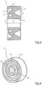
- the buffer unit 9 has a ring cross-section 13 which is Z-shaped. Furthermore, the buffer unit 9 comprises an in FIG. 3 Left side shown a projection 14 which projects parallel to a longitudinal axis 15 of the buffer unit 9 via a left end face 16 of the buffer unit 9 .
- the ring cross-section 13 of the buffer unit 9 has two circumferential recesses 17 , which are formed in the ring cross-section 13 in such a way that the remaining or "standing" material of the ring cross-section 13 forms the characteristic Z-shape. This is characterized in that it comprises two parallel flange portions 18 and an inclined center web 19 .
- the central web 19 extends from the projection 14 to an opposite end face of the buffer unit 9, wherein a radial distance of the central web 19 from the longitudinal axis 15 of the buffer unit 9 increases steadily.
- the buffer unit 9 is in the FIGS. 3 and 4 shown in a power-free state in which the buffer unit 9 is undeformed.
- An introduction of force from the guide device 5 into the buffer unit 9 or into the connecting means 11 immediately causes a deformation of the buffer unit 9, the latter being simultaneously "pressed” and "pulled". It is self-evident that a direction of action of a force acting on the buffer unit 9 is constant, so that the buffer unit 9 is charged exactly opposite to positions opposite relative to the connecting means 11 and is correspondingly deformed.
- a tensile force can be transmitted from the outer flange portion 18 to the inner flange portion 18 .
- the buffer units 9 are advantageously arranged on the uppercarriage 4 such that the projection 14 faces the uppercarriage 4 .
- a further buffer unit 9 ' has a W-shaped ring cross section 13' .
- This fact does not extend between opposite ends of the opposed flange portions 18 of the ring cross section 13 ', but extends between two corresponding ends of the opposed flange portions 18.
- the central web 19' In a center portion extending between the flange portions 18, the central web 19' a V Shape up. From the illustration, it can be seen that the annular cross-section 13 ', comparable to the annular cross-section 13, has two circumferential recesses 17' .
- FIG. 7 an exemplary force-deformation diagram 20 is shown, which represents a development of a rigidity of a buffer unit 9, 9 ' under the action of a force.
- the deformation of the buffer unit 9 and on the y-axis the force acting on the buffer unit 9 is shown.
- the buffer unit 9 has a starting stiffness.
- the starting stiffness is relatively low, as can be seen from the already occurring under the action of small forces large deformations.
- the limit force 21 represents the force at which the recesses 17 of the ring cross section 13, 13 'are completely compressed.
- the buffer unit 9, 9 ' has a limit deformation 22 .
- the achievement of the limit force 21 or the limit deformation 22 has the consequence that the buffer unit 9, 9 ' stiffened abruptly, since a further deformation of the opposing flange portions 18 to each other is no longer possible.
- the buffer unit 9 consequently has a final rigidity after reaching the limit force 21 or the limit deformation 22 , which considerably exceeds the starting stiffness. It goes without saying that a vibration of the superstructure 4 can be buffered particularly effectively if the buffer unit 9, 9 ' still has its starting rigidity, that is to say is not yet so strongly deformed that the recesses 17 are completely compressed.
Description
Die vorliegende Erfindung betrifft eine Vorrichtung zum Verdichten eines Untergrundes gemäß dem Oberbegriff von Anspruch 1.The present invention relates to a device for compacting a substrate according to the preamble of
Unter einer "Bodenkontakteinheit" wird im Sinne der vorliegenden Anmeldung eine Einheit verstanden, die unmittelbar mit den jeweilig zu bearbeiten Untergrund in Kontakt tritt. Bei einer Vorrichtung, die als Vibrationsplatte ausgeführt ist, ist eine derartige Bodenkontakteinheit in der Regel von einer planen Metallplatte gebildet, die mittels eines Schwingungserregers in eine Schwingung versetzbar ist.For the purposes of the present application, a "ground contact unit" is understood to mean a unit which comes into direct contact with the respective substrate to be processed. In a device which is designed as a vibration plate, such a ground contact unit is usually formed by a flat metal plate, which is displaceable by means of a vibration exciter in a vibration.
Unter einer "Führungseinrichtung" wird im Sinne der vorliegenden Anmeldung eine Einrichtung verstanden, mittels derer die Vorrichtung führbar ist, das heißt der Vorrichtung eine Richtungsänderung aufprägbar ist und die Vorrichtung schiebbar und ziehbar ist. Bekannte Vorrichtungen der eingangs beschriebenen Art weisen in einem Betriebszustand, in der der Schwingungserreger aktiv ist, einen "automatischen Gerardeauslauf" auf, sodass ein Eingriff des Nutzers der Vorrichtung im Sinne des Aufbringen einer Lenkbewegung oder dergleichen in der Regel nicht notwendig ist. Bei der Führungseinrichtung handelt es sich im Sinne der vorliegenden Anmeldung in jedem Fall um eine solche, die von einem Nutzer der Vorrichtung unmittelbar bedient wird. Das heißt, dass die Führungseinrichtung nicht im Sinne einer ferngesteuerten Führung wirkt.For the purposes of the present application, a "guiding device" is understood to be a device by means of which the device can be guided, that is, the device can be changed in direction and the device can be pushed and pulled. Known devices of the type described above have an "automatic Gerardeauslauf" in an operating state in which the vibration exciter is active, so that an intervention of the user of the device in the sense of applying a steering movement or the like is usually not necessary. In the sense of the present application, the guide device is in any case one which is operated directly by a user of the device. This means that the guide device does not act in the sense of a remote-controlled guidance.
Bei dem genannten "Schwingungserreger" handelt es sich in aller Regel um einen Exzenter, der typischerweise mittels eines Verbrennungsmotors angetrieben wird. Der Exzenter erzeugt mittels einer Bewegung einer Masse um eine exzentrisch angeordnete Achse eine Schwingung, mittels derer zumindest die Bodenkontakteinheit in die gewünschte Vibration versetzbar ist.The mentioned "vibration exciter" is usually an eccentric, which is typically driven by an internal combustion engine. The eccentric generates by means of a movement of a mass about an eccentrically arranged axis a vibration, by means of which at least the ground contact unit is displaceable in the desired vibration.
Gewissermaßen das Gegenteil des hier beschriebenen "Betriebszustandes" ist ein "Ruhezustand". Unter diesem Ruhezustand wird ein Zustand der Führungseinrichtung verstanden, in dem diese frei von äußeren Kräften ist. Insbesondere wird in dem Ruhezustand die Führungseinrichtung der Vorrichtung nicht verwendet und ist demzufolge allein der aufgrund ihres Eigengewichts wirkenden Gewichtskraft ausgesetzt. Die Puffereinheit liegt in diesem Ruhezustand folglich in einem im Wesentlichen unverformten Zustand vor, da eine Übertragung von Kräften von der Führungseinrichtung auf den Oberwagen nicht stattfindet.To some extent the opposite of the "operating state" described here is a "resting state". Under this rest state is understood a state of the guide device in which it is free of external forces. In particular, in the idle state, the guide device of the device is not used and is therefore exposed solely to the weight force acting on its own weight. The buffer unit is thus in a non-deformed state in this resting state Condition before, since a transfer of forces from the guide device does not take place on the superstructure.
Ein "miteinander in Kontakt stehen" von Oberflächen des Verbindungsmittels und der Puffereinheit ist so zu verstehen, dass diese Oberflächen aneinander anliegen, sodass ein Kraftfluss von der Puffereinheit zu dem Verbindungsmittel und umgekehrt möglich ist. Hierzu ist es nicht zwingend erforderlich, dass zwischen entsprechenden Oberflächen der Puffereinheit und des Verbindungsmittels ein vollflächiger Kontakt vorliegt. Stattdessen ist es ebenso denkbar, dass lediglich ein Teil korrespondierender Oberflächen von Puffereinheit und Verbindungsmittel in Kontakt stehen. Gleichwohl kann es vorteilhaft sein, wenn zwischen entsprechenden Oberflächen der Puffereinheit und des Verbindungsmittels ein vollflächiger Kontakt besteht.A "contacting" surfaces of the bonding means and the buffering unit is understood to mean that these surfaces abut each other so that power flow from the buffering unit to the bonding means and vice versa is possible. For this purpose, it is not absolutely necessary that there is a full-area contact between corresponding surfaces of the buffer unit and the connecting means. Instead, it is also conceivable that only a part of corresponding surfaces of the buffer unit and connecting means are in contact. However, it may be advantageous if there is a full-surface contact between corresponding surfaces of the buffer unit and the connecting means.
Eine Richtung, die hier als "radial zur Drehachse" bezeichnet ist, ist senkrecht zu der Drehachse der Vorrichtung orientiert. Eine Überlappung der Führungseinrichtung und der Puffereinheit in dem Überlappungsbereich bedeutet mithin, dass bei einem gedachten Schnitt radial zu der Drehachse innerhalb des Überlappungsbereichs sowohl die Puffereinheit als auch die Führungseinrichtung geschnitten werden. Eine derartige Ausführung ist in dem vorstehend genannten Stand der Technik nicht gegeben, da die dortige Anschlussplatte parallel zu einer Stirnseite der dortigen Puffereinheit orientiert sowie an dieser Stirnseite angeordnet ist; mithin ist dort kein Schnitt radial zu der dortigen Drehachse führbar, mittels dessen sowohl das dortige Verbindungsmittel als auch die dortige Puffereinheit geschnitten werden.A direction, referred to herein as "radial to the axis of rotation", is oriented perpendicular to the axis of rotation of the device. An overlap of the guide device and the buffer unit in the overlap region therefore means that, in the case of an imaginary cut radially to the axis of rotation within the overlap region, both the buffer unit and the guide device are cut. Such Embodiment is not given in the above-mentioned prior art, since the local terminal plate is oriented parallel to an end face of the local buffer unit and arranged on this end face; Consequently, there is no section radially to the local axis of rotation feasible, by means of which both the local connection means and the local buffer unit are cut.
Vorrichtungen der eingangs beschriebenen Art sind aus dem Stand der Technik bereits bekannt. Sie werden typischerweise zur Verdichtung eines Untergrundes eingesetzt. Diese erfolgt dadurch, dass die in eine Schwingung versetzte Bodenkontakteinheit "rüttelnd" auf den jeweiligen Untergrund einwirkt. Aufgrund einer Masse der Vorrichtung werden die einzelnen Partikel, von denen der Untergrund gebildet ist, verdichtet. Auf diese Weise ist es möglich, den Untergrund gewissermaßen zu versteifen, sodass dieser unter einer nachfolgend aufgebrachten Belastung, beispielsweise einem darauf zu erstellenden Gebäude oder Trasse, lediglich in einem reduzierten Umfang nachgibt und es nicht zu unerwünschten Setzungen kommt.Devices of the type described above are already known from the prior art. They are typically used to compact a substrate. This takes place in that the floor contact unit "vibrated", which is set in oscillation, acts on the respective substrate. Due to a mass of the device, the individual particles, of which the substrate is formed, compacted. In this way, it is possible to stiffen the substrate to some extent, so that this yields under a subsequently applied load, such as a building or route to be created on it, only to a reduced extent and there are no unwanted settlements.
Insbesondere aus der
Um dies zu erreichen, ist die Puffereinheit der im Stand der Technik bekannten Vorrichtung von einem elastischen Material gebildet, sodass sie sich besonders leicht verformen kann. Die Puffereinheit ist derart an dem Oberwagen der Vorrichtung angeordnet, dass sie gewissermaßen als Zwischenelement zwischen der Führungseinrichtung und dem Oberwagen wirkt. Das heißt, dass die Führungseinrichtung und der Oberwagen in keinem unmittelbaren Kontakt stehen, sondern Kräfte, die zwischen der Führungseinrichtung und dem Oberwagen fließen, in jedem Fall ausschließlich mittels der Puffereinrichtung übertragen werden.To achieve this, the buffer unit of the device known in the prior art is formed of an elastic material, so that it can deform particularly easily. The buffer unit is arranged on the superstructure of the device such that it acts as a kind of intermediate element between the guide device and the superstructure. That is, the guide means and the superstructure are not in direct contact, but forces flowing between the guide means and the superstructure are transmitted in each case exclusively by means of the buffer means.
Wenngleich die "Abpufferung" der Vibrationen des Oberwagens aus den genannten Gründen erwünscht ist, so ist eine hierdurch bedingt indirekte Übertragung von Bewegungen der Führungseinrichtung auf den Oberwagen im Hinblick auf eine Führung des Oberwagens grundsätzlich nachteilig. Die genannte schwammige Übertragung kommt durch die Elastizität der Puffereinheit zustande, die dazu führt, dass eine Lenkbewegung, die auf die Führungseinrichtung ausgeübt wird, lediglich in einer abgepufferten Form auf den Oberwagen übertragen wird. Zu diesem Zweck ist die Puffereinheit gemäß der oben genannten
Um eine Pufferwirkung der Puffereinheit zu gewährleisten, ist es von besonderer Bedeutung, dass ein Kontakt von Metall auf Metall vermieden wird. Aufgrund der hohen Steifigkeit von Metall führt ein solcher Kontakt nämlich zu einer unmittelbaren Übertragung der Vibration des Oberwagens auf die Führungseinrichtung. Um einen direkt Kontakt zwischen metallischen Teilen der Führungseinrichtung und des Oberwagens zu vermeiden, ist die Puffereinheit gemäß dem genannten Dokument des Standes der Technik auf eine Anschlussplatte aufvulkanisiert, die an dem Oberwagen befestigt ist. Diese Anschlussplatte dient ausschließlich der Verbindung des Oberwagens mit der Puffereinheit; ein Kontakt zwischen der Anschlussplatte und der Führungseinrichtung tritt nicht auf.In order to ensure a buffering effect of the buffer unit, it is of particular importance that contact between metal and metal is avoided. Because of the high rigidity of metal, such a contact leads namely to an immediate transmission of the vibration of the upper carriage on the guide device. In order to avoid direct contact between metallic parts of the guide device and the superstructure, the buffer unit is vulcanized according to the cited prior art document on a connection plate which is fixed to the superstructure. This connection plate is used exclusively for connecting the superstructure with the buffer unit; a contact between the terminal plate and the guide means does not occur.
Die Anschlussplatte ist an einer dem Oberwagen zugewandten Stirnseite der Puffereinheit angeordnet. Ein Kraftfluss zwischen der Führungseinrichtung und dem Oberwagen erfolgt demzufolge ausgehend von der Führungseinrichtung in die Puffereinheit und von dort mittels der Anschlussplatte in den Oberwagen. Auf die Puffereinheit einwirkende Kräfte werden folglich mittels Drehmomenten und Scherkräften in die Anschlussplatte abgetragen. Die Einleitung einer Kraft von der Führungseinrichtung in die Puffereinheit erfolgt von der Anschlussplatte aus betrachtet daher in jedem Falle ausmittig. Diese Art der Belastung ist für die Verbindung der elastischen und vergleichsweise weichen Puffereinheit mit der steifen Anschlussplatte nachteilig. Insbesondere treten in Randbereichen der Anschlussplatte Spannungsspitzen auf, die für eine Dauerhaftigkeit der Verbindung beider Teile von Nachteil sind.The connection plate is arranged on an end face of the buffer unit facing the superstructure. A power flow between the guide device and the superstructure is therefore carried out starting from the guide device in the buffer unit and from there by means of the connecting plate in the superstructure. On the buffer unit acting forces are thus removed by means of torques and shear forces in the connection plate. The introduction of a force from the guide device in the buffer unit is therefore carried out from the connection plate from view in each case outwardly. This type of loading is disadvantageous for the connection of the elastic and comparatively soft buffer unit with the rigid connection plate. In particular, in the edge regions of the connection plate, voltage peaks occur that are detrimental to a durability of the connection between the two parts.
Ein weiteres im Stand der Technik bekanntes Beispiel, dass ein ringförmig ausgebildetes Pufferelement zeigt, ergibt sich aus den
Der vorliegenden Erfindung liegt daher die Aufgabe zugrunde, eine Vorrichtung zur Verfügung zu stellen, deren Verbindung der Führungseinrichtung und des Oberwagen gegenüber dem Stand der Technik verbessert ist.The present invention is therefore based on the object to provide a device available whose connection of the guide device and the superstructure over the prior art is improved.
Die zugrunde liegende Aufgabe wird ausgehend von einer Vorrichtung der eingangs beschriebenen Art erfindungsgemäß durch eine Vorrichtung mit den Merkmalen des Anspruchs 1 gelöst. Vorteilhafte Ausgestaltungen ergeben sich aus den Unteransprüchen 2 bis 14.The underlying object is achieved on the basis of a device of the type described above according to the invention by a device having the features of
Die erfindungsgemäße Vorrichtung hat viele Vorteile. Insbesondere ist ein gegenüber dem Stand der Technik verbesserter Kraftfluss zwischen dem Verbindungsmittel und der Puffereinheit möglich. Dies liegt darin begründet, dass sich das Verbindungsmittel "entlang" zumindest eines Teils einer Längsachse der Puffereinheit erstreckt, sodass eine ausmittige Belastung des Verbindungsmittels, wie sie im Stand der Technik vorliegt, zumindest reduziert ist. Die Längsachse der Puffereinheit ist parallel zu der Drehachse orientiert. Dabei ist es grundsätzlich unerheblich, ob sich das Verbindungsmittel innerhalb der Puffereinheit erstreckt oder ob es die Puffereinheit umgibt. In jedem Fall wirkt das Verbindungsmittel nicht lediglich an einer Stirnseite der Puffereinheit, sondern ermöglicht eine Einleitung einer Kraft in das Verbindungsmittel in einem ausgehend von der Stirnseite nach Innen gewandten Bereich. Das Verbindungsmittel kann insbesondere von einem Bolzen oder einem Rohrelement gebildet sein. Ebenso sind andere Ausführungen des Verbindungsmittels vorstellbar. In jedem Fall ist es vorteilhaft, wenn das Verbindungsmittel von einem widerstandsfähigen Material gebildet ist, insbesondere von einem metallischen Material. Ein derartiges Verbindungsmittel ist besonders gut dazu geeignet, einwirkende Kräfte in den Oberwagen abzuleiten. Hierbei versteht es sich, dass ein derartiges Verbindungsmittel gegenüber der Puffereinheit gemäß dem Stand der Technik besser geeignet ist, um von der Führungseinrichtung auf die Puffereinheit einwirkende Kräfte mittels Biegemomenten und Scherkräften abzutragen.The device according to the invention has many advantages. In particular, an improved compared to the prior art power flow between the connecting means and the buffer unit is possible. This is due to the fact that the connecting means extends "along" at least part of a longitudinal axis of the buffer unit, so that an off-center loading of the connecting means, as present in the prior art, is at least reduced. The longitudinal axis of the buffer unit is oriented parallel to the axis of rotation. It is basically irrelevant whether the connecting means extends within the buffer unit or whether it surrounds the buffer unit. In any case, the connecting means not only acts on an end face of the buffer unit, but allows an introduction of a force in the connecting means in a starting from the end face inwardly facing area. The connecting means may in particular be formed by a bolt or a tubular element. Likewise, other embodiments of the connecting means are conceivable. In any case, it is advantageous if the connecting means is formed of a resistant material, in particular of a metallic material. Such a connecting means is particularly well suited to dissipate acting forces in the superstructure. It is understood that such a connection means is better suited than the buffer unit according to the prior art for removing forces acting on the buffer unit from the guide device by means of bending moments and shearing forces.
Ein weiterer Vorteil der erfindungsgemäßen Vorrichtung besteht in dessen besonders einfacher Herstellung. Insbesondere ist es nicht notwendig, die Puffereinheit auf einer Anschlussplatte aufzuvulkanisieren. Stattdessen können die Puffereinheit und das Verbindungsmittel durch "Aufschieben" miteinander verbunden werden, das heißt mittels einer Bewegung der Puffereinheit und des Verbindungsmittels relativ zueinander in eine Richtung parallel zu der Längsachse der Puffereinheit.Another advantage of the device according to the invention is its particularly simple production. In particular, it is not necessary to vulcanize the buffer unit on a connection plate. Instead, the buffer unit and the connecting means may be interconnected by "pushing", that is, by means of a movement of the buffer unit and the connecting means relative to each other in a direction parallel to the longitudinal axis of the buffer unit.
Die Ausbildung des Ringquerschnitts der Puffereinheit ist für dessen puffernde Wirkung von besonderer Bedeutung. Dem liegt die Überlegung zugrunde, dass unabhängig von dem Material, von dem die Puffereinheit gebildet ist, allein durch die Ausgestaltung des Ringquerschnitts bereits eine puffernde Wirkung erzeugt werden kann. Dies ist insbesondere dadurch möglich, dass der Ringquerschnitt nicht als Vollquerschnitt, sondern als "aufgelöster" Querschnitt ausgeführt wird. Hierunter wird ein solcher Querschnitt verstanden, der gegenüber einem Vollquerschnitt bzw. einem massiven Querschnitt mindestens eine Ausnehmung aufweist. Das heißt, dass einem solchen Ringquerschnitt gegenüber einem Vollquerschnitt Material entnommen ist. Hierdurch wird eine Steifigkeit der Puffereinheit reduziert oder mit anderen Worten dessen Elastizität gesteigert. Es versteht sich also, dass ein solcher, mit mindestens einer Ausnehmung, möglicherweise mit mehreren Ausnehmungen, versehener Ringquerschnitt allein aufgrund seiner Geometrie zumindest eine gewisse Pufferwirkung aufweist.The formation of the ring cross section of the buffer unit is of particular importance for its buffering effect. This is based on the consideration that regardless of the material from which the buffer unit is formed, already by the design of the ring cross-section already a buffering effect can be generated. This is possible in particular in that the ring cross section is not executed as a solid cross section, but as a "resolved" cross section. This is understood as meaning such a cross-section which has at least one recess in relation to a solid cross section or a solid cross section. This means that such a ring cross section is taken from a solid cross section material. This reduces rigidity of the buffer unit or, in other words, increases its elasticity. So it goes without saying that such, with at least one recess, possibly with a plurality of recesses, provided ring cross-section alone due to its geometry has at least a certain buffer effect.
Letztere ergibt sich aus der reduzierten Steifigkeit der Puffereinheit. Die reduzierte Steifigkeit hat wiederum zur Folge, dass die Eigenfrequenz der Puffereinheit bzw. einer gedachten Einheit aus Puffereinheit und Führungseinrichtung sinkt. Die Puffereinheit ist so ausgebildet, dass ihre Eigenfrequenz deutlich unterhalb der Erregerfrequenz des Schwingungserregers liegt. Hierdurch wird eine Anregung der Puffereinheit und folglich auch der Führungseinrichtung im Wesentlichen vermieden; insbesondere kann keine Verstärkung der Schwingung des Schwingungserregers an der Führungseinrichtung auftreten. Die Schersteifigkeit einer Puffereinheit ist vorzugsweise erheblich geringer als deren Längssteifigkeit, insbesondere um mindestens den Faktor 10. Die Längssteifigkeit beschreibt dabei diejenige Steifigkeit der Puffereinheit, die diese radial zu der Drehachse aufweist. Die Schersteifigkeit bezeichnet die Steifigkeit, die die Puffereinheit parallel zu der Drehachse aufweist.The latter results from the reduced rigidity of the buffer unit. The reduced stiffness in turn means that the natural frequency of the buffer unit or an imaginary unit of buffer unit and guide device decreases. The buffer unit is designed so that its natural frequency is well below the excitation frequency of the vibration exciter. As a result, an excitation of the buffer unit and consequently also of the guide device is substantially avoided; in particular, no amplification of the oscillation of the vibration exciter on the guide device can occur. The shear stiffness of a buffer unit is preferably considerably less than its longitudinal rigidity, in particular by at least the
Für die Wirkung der Puffereinheit ist es besonders vorteilhaft, wenn die "ausschließliche Kraftübertragung" zwischen der Führungseinrichtung und dem Oberwagen im Sinne der vorliegenden Anmeldung während des Betriebszustands nicht lediglich zeitweise, sondern im Wesentlichen durchgängig vorliegt. Eine Unterbrechung einer solchen "ausschließlichen" Kraftübertragung kann beispielsweise dadurch auftreten, dass mittels der Führungseinrichtung ein um eine horizontale Achse wirkendes Drehmoment aufgebracht werden soll. Ein solches Drehmoment ist dazu geeignet, die Vorrichtung an einem der Führungseinrichtung abgewandten Ende anzuheben. Dies kann insbesondere bei Lenkbewegungen gewünscht sein. Das Drehmoment wird in der Regel durch Zusammenwirken zweier Verbindungsstellen von Führungseinrichtung und Oberwagen erzeugt, wobei mittels dieser Verbindungsstellen ein Kräftepaar an den Oberwagen übertragbar ist. Dieses Kräftepaar bewirkt das beschriebene Drehmoment. Zusätzlich zu einer Verbindungsstelle, an der die Puffereinheit wirkt, kann demzufolge zumindest eine zweite Verbindungsstelle vorhanden sein, gegen die die Führungseinrichtung abstützbar ist, um das beschriebene Drehmoment aufzubringen. Bei Kontakt der Führungseinrichtung mit dieser zweiten Verbindungsstelle kommt es zeitweise - typischerweise lediglich kurz - zu einer Kraftübertragung zwischen der Führungseinrichtung und dem Oberwagen, die nicht mittels der Puffereinheit erfolgt. Für den erfindungsgemäßen Erfolg ist dies unschädlich.For the effect of the buffer unit, it is particularly advantageous if the "exclusive power transmission" between the guide device and the superstructure in the context of the present application during the operating state is not only temporarily, but substantially continuous. An interruption of such an "exclusive" power transmission, for example, occur in that by means of the guide device acting on a horizontal axis torque is to be applied. Such a torque is suitable for lifting the device at an end facing away from the guide device. This may be desired in particular during steering movements. The torque is generally generated by the interaction of two connecting points of the guide device and the uppercarriage, wherein a pair of forces can be transmitted to the uppercarriage by means of these connection points. This pair of forces causes the torque described. Accordingly, in addition to a connection point on which the buffer unit acts, at least one second connection point can be present, against which the guide device can be supported in order to apply the described torque. Upon contact of the guide device with this second connection point, there is at times - typically only briefly - a force transmission between the guide device and the superstructure, which does not take place by means of the buffer unit. This is harmless for the success of the invention.
In einer vorteilhaften Ausgestaltung der erfindungsgemäßen Vorrichtung erstreckt sich das Verbindungsmittel in eine zu der Drehachse parallelen Richtung zumindest über eine gesamte Länge der Puffereinheit. Das heißt, dass bei einem beliebig gesetzten Schnitt durch die Puffereinheit radial zu der Drehachse in jedem Fall sowohl die Puffereinheit als auch das Verbindungsmittel geschnitten werden. Diese Ausführung hat den Vorteil, dass eine Kontaktfläche, die sich zwischen den korrespondierenden Oberflächen des Verbindungsmittels sowie der Puffereinheit ausbilden, maximal ist. Dies führt dazu, dass zwischen der Puffereinheit und dem Verbindungsmittel zu übertragende Kräfte auf eine maximale Fläche verteilt werden können. Insbesondere die Puffereinheit, die in der Regel elastisch ausgebildet ist, ist infolgedessen einer vergleichsweise geringen Flächenpressung ausgesetzt. Außerdem ist es vorstellbar, dass sich das Verbindungsmittel über die Puffereinheit hinaus erstreckt, das heißt über ein dem Oberwagen abgewandtes Ende der Puffereinheit vorsteht. Dies kann insoweit vorteilhaft sein, als dieses über die Puffereinheit überstehende Ende des Verbindungsmittels mit einem Fixierelement versehen werden kann, das sich im Wesentlichen in eine zur Drehachse radiale Richtung erstreckt. Ein solches Fixierelement ist dazu geeignet, mit einer dem Oberwagen abgewandten Stirnfläche der Puffereinheit formschlüssig einzugreifen und auf diese Weise eine Bewegung der Puffereinheit in eine dem Oberwagen abgewandte Richtung relativ zu dem Verbindungsmittel zu blockieren. Ein solches Fixierelement kann insbesondere von einem Sicherungsstift gebildet sein, der sich radial zur Drehachse erstreckt.In an advantageous embodiment of the device according to the invention, the connecting means extends in a direction parallel to the axis of rotation at least over one entire length of the buffer unit. That is to say that in any arbitrary cut through the buffer unit radially to the axis of rotation in each case both the buffer unit and the connecting means are cut. This embodiment has the advantage that a contact surface, which form between the corresponding surfaces of the connecting means and the buffer unit, is maximum. As a result, forces to be transmitted between the buffer unit and the connection means can be distributed to a maximum area. In particular, the buffer unit, which is usually elastic, is consequently exposed to a comparatively low surface pressure. In addition, it is conceivable that the connecting means extends beyond the buffer unit, that is to say projects beyond an end of the buffer unit facing away from the uppercarriage. This can be advantageous insofar as this end of the connecting means projecting beyond the buffer unit can be provided with a fixing element which extends substantially in a direction radial to the axis of rotation. Such a fixing element is adapted to engage positively with an end face of the buffer unit facing away from the superstructure and in this way to block a movement of the buffer unit in a direction away from the superstructure relative to the connecting means. Such a fixing element may in particular be formed by a securing pin which extends radially to the axis of rotation.
Weiterhin ist es von Vorteil, wenn sich die Führungseinrichtung und die Puffereinheit derart überlappen, dass sich das Verbindungsmittel in die Puffereinheit hinein erstreckt. In einer solchen Ausgestaltung umschließt die Puffereinheit das Verbindungsmittel zumindest teilweise, das heißt das Verbindungsmittel befindet sich gewissermaßen "innerhalb" der Puffereinheit. Vorzugsweise umschließt die Puffereinheit das Verbindungsmittel vollständig, sodass eine innere Oberfläche der Puffereinheit vollständig mit einer äußeren Oberfläche des Verbindungsmittels zusammenwirkt. Hierbei ist es durchaus vorstellbar, dass sich das Verbindungsmittel über die Puffereinheit hinaus erstreckt, wobei ein Teil einer äußeren Oberfläche des Verbindungsmittels nicht von der Puffereinheit umschlossen ist.Furthermore, it is advantageous if the guide device and the buffer unit overlap in such a way that the connecting means extends into the buffer unit. In such an embodiment, the buffer unit encloses the connecting means at least partially, that is, the connecting means is located to a certain extent "within" the Buffer unit. Preferably, the buffer unit completely encloses the connecting means so that an inner surface of the buffer unit fully cooperates with an outer surface of the connecting means. Here, it is quite conceivable that the connecting means extends beyond the buffer unit, wherein a part of an outer surface of the connecting means is not enclosed by the buffer unit.
Im Hinblick auf die Puffereinheit kann es besonders vorteilhaft sein, wenn selbige rotationssymmetrisch ausgebildet ist. Hieraus ergibt sich unabhängig von einer Drehstellung der Führungseinrichtung relativ zu dem Oberwagen eine stets gleichbleibende Kraftübertragung zwischen der Puffereinheit und dem Verbindungsmittel, da ein Querschnitt der Puffereinheit unabhängig von der Drehstellung in jedem Falle gleich ist.With regard to the buffer unit, it may be particularly advantageous if the same is rotationally symmetrical. It follows that regardless of a rotational position of the guide means relative to the superstructure always a constant power transmission between the buffer unit and the connecting means, since a cross section of the buffer unit regardless of the rotational position in each case is the same.
In einer weiterhin vorteilhaften Ausbildung der erfindungsgemäßen Vorrichtung erstreckt sich die mittige Ausnehmung über die gesamte Länge der Puffereinheit. Letztere bildet um diese Ausnehmung herum den Ringquerschnitt aus, der die Ausnehmung umlaufend umschließt. Das heißt, dass bei einem Schnitt durch die Puffereinheit, bei dem auch die Ausnehmung geschnitten wird, der umlaufende Ringquerschnitt insgesamt zweimal geschnitten wird. Eine derartige Ausnehmung ist besonders gut geeignet, das Verbindungsmittel des Oberwagens aufzunehmen. Eine Ausbildung der Ausnehmung über die gesamte Länge der Puffereinheit ist dabei insbesondere aus fertigungstechnischen Gründen vorteilhaft.In a further advantageous embodiment of the device according to the invention, the central recess extends over the entire length of the buffer unit. The latter forms around this recess around the ring cross-section, which surrounds the recess circumferentially. This means that in a cut through the buffer unit, in which the recess is also cut, the circumferential annular cross-section is cut twice in total. Such a recess is particularly well suited to receive the connecting means of the upper carriage. A design of the recess over the entire length of the buffer unit is particularly advantageous for manufacturing reasons.
Als Querschnittsformen für den Ringquerschnitt können insbesondere ein Z-förmiger oder ein W-förmiger Querschnitt vorteilhaft sein. Diese Querschnittsformen bezeichnen jeweils eine Form des Ringquerschnitts in dem Ruhezustand der Führungseinrichtung, das heißt in einem Zustand, in dem die Puffereinheit im Wesentlichen frei von äußeren Kräften und folglich unverformt ist. Es hat sich herausgestellt, dass die genannte Z-Form sowie die genannte W-Form für eine Pufferwirkung der Puffereinheit besonders vorteilhaft sind. Insbesondere sind derartige Puffereinheiten in eine Richtung radial zu der Drehachse relativ leicht verformbar, das heißt dass sie ausgehend von einer Nullstellung, in der die Puffereinheit unverformten ist, in eine Auslenkungsstellung verformbar sind. Diese Auslenkungsstellung ist zumindest dann erreicht, wenn die Puffereinheit an zumindest einer Stelle entlang ihres Ringquerschnitts derart verformt ist, dass sich gewissermaßen ein Vollquerschnitt ausbildet. Mit anderen Worten sind in der Auslenkungsstellung die vorstehend beschriebenen Ausnehmungen des Ringquerschnitts vollständig "zusammengedrückt", sodass an der jeweiligen Stelle ein gegenüber dem Ringquerschnitt in der Nullstellung der Puffereinheit reduzierter Querschnitt vorliegt, der jedoch keine Ausnehmungen mehr aufweist.As a cross-sectional shapes for the ring cross-section, in particular a Z-shaped or a W-shaped cross section may be advantageous. These cross-sectional shapes each indicate a shape of the ring cross section in the resting state of the guide means, that is, in a state where the buffer unit is substantially free from external forces and hence undeformed. It has been found that said Z-shape and said W-shape are particularly advantageous for buffering the buffer unit. In particular, such buffer units are relatively easily deformable in a direction radial to the axis of rotation, that is to say that they can be deformed into a deflection position starting from a zero position in which the buffer unit is undeformed. This deflection position is at least achieved when the buffer unit is deformed at least at one point along its annular cross-section such that, as it were, a solid cross-section is formed. In other words, in the deflection position, the above-described recesses of the ring cross-section are completely "compressed", so that at the respective point a reduced cross-section with respect to the ring cross-section in the zero position of the buffer unit is present, which, however, has no recesses.
Dies führt dazu, dass die Puffereinheit zumindest an dieser Stelle des Ringquerschnitts versteift, da eine weitere Verformung nicht ohne Weiteres möglich ist. Stattdessen wirkt einer einwirkenden äußeren Kraft nunmehr die dem Material der Puffereinheit innewohnende Materialsteifigkeit, der sogenannte E-Modul, entgegen. Das bedeutet, dass bei einer Einwirkung einer Kraft auf die Führungseinrichtung und folglich auf die Puffereinheit die Puffereinheit zunächst eine geringe Steifigkeit aufweist, sich jedoch versteift, sobald sie ihre Auslenkungsstellung erreicht. Solange die einwirkende Kraft nicht ausreicht, um die Puffereinrichtung bis in ihre Auslenkungsstellung zu verformen, setzt die Puffereinheit ebenjener Kraft eine vergleichsweise geringe Steifigkeit entgegen, die sich - wie vorstehend erläutert - aus der aufgelösten Geometrie des Ringquerschnitts ergibt. Erst wenn die Kraft einen Betrag erreicht, der dazu geeignet ist, den Ringquerschnitt vollständig an einer Stelle zusammenzudrücken, tritt die beschriebene Versteifung ein. Diese Kraft wird hier als "Grenzkraft" bezeichnet.As a result, the buffer unit stiffened at least at this point of the ring cross-section, since further deformation is not readily possible. Instead, an acting external force now counteracts the material stiffness inherent in the material of the buffer unit, the so-called modulus of elasticity. This means that when a force is exerted on the guide device and consequently on the buffer unit, the buffer unit initially has a low rigidity, but stiffens as soon as it reaches its deflection position. As long as the acting force is not sufficient to deform the buffer device into its deflection position, the buffer unit sets just that force against a comparatively low rigidity, which, as explained above, results from the resolved geometry of the ring cross section. Only when the force reaches an amount which is capable of completely compressing the ring cross-section at one point, the stiffening described occurs. This force is referred to here as "limit force".
Dieses Verhalten der Puffereinheit ist insoweit wünschenswert, als es in jedem Falle möglich sein muss, mittels der Führungseinrichtung nennenswerte Kräfte auf die Vorrichtung bzw. den Oberwagen zu übertragen, um die Vorrichtung zuverlässig führen bzw. lenken zu können. Für die Einleitung derartiger Kräfte von der Führungseinrichtung in den Oberwagen ist die elastische Ausbildung der Puffereinheit eigentlich nachteilig. Gleichwohl ist diese aus den eingangs erläuterten Gründen erforderlich, um eine Vibration des Oberwagens möglichst effektiv von der Führungseinrichtung zu entkoppeln. Die hier beschriebene Funktionsweise findet einen Kompromiss zwischen beiden Aufgaben, indem eine Versteifung der Puffereinheit, die selbstverständlich auch mit einer gesteigerten Übertragung der Vibrationen des Oberwagens auf die Führungseinrichtung einhergeht, immer nur dann eintritt, wenn die Vorrichtung unter Zuhilfenahme großer Führungskräfte gelenkt werden muss. Dies ist in aller Regel nur über kurze Zeiträume während des Betriebs der Vorrichtung hinweg erforderlich, sodass die Beeinträchtigung des Führungskomforts der Vorrichtung in einem nicht nennenswerten Maß reduziert wird.This behavior of the buffer unit is desirable inasmuch as it must be possible in any case to transmit significant forces to the device or the superstructure by means of the guide device in order to be able to guide or steer the device reliably. For the introduction of such forces from the guide device in the superstructure, the elastic design of the buffer unit is actually disadvantageous. However, this is necessary for the reasons explained above, to decouple a vibration of the superstructure as effectively as possible from the guide device. The operation described here finds a compromise between the two tasks by stiffening the buffer unit, which of course is accompanied by an increased transmission of vibrations of the superstructure on the guide device, only ever occurs when the device must be steered with the help of large executives. This is usually required only for short periods during the operation of the device, so that the impairment of the guiding comfort of the device is reduced to an insignificant extent.
Weiterhin kann eine solche Ausführungsform der erfindungsgemäßen Vorrichtung von Vorteil sein, bei der die Puffereinheit an einer dem Oberwagen zugewandten Stirnseite einen axialen Vorsprung aufweist. Dieser axiale Vorsprung ist derart an der Puffereinheit positioniert, dass er mit einer seitlichen Stirnseite dem Oberwagen zugewandt ist und zumindest zeitweise, vorzugsweise durchgängig, mit ebenjener Stirnseite an dem Oberwagen anliegt. Der axiale Vorsprung erstreckt sich dabei parallel zu der Drehachse, das heißt parallel zu einer Längsachse der Puffereinheit. Er kann insoweit vorteilhaft sein, als ein Abstand zwischen der "eigentlichen" Puffereinheit und dem Oberwagen in jedem Fall zumindest der Länge des Vorsprungs entspricht, die dieser gemessen in eine Richtung parallel zu der Drehachse aufweist. Unter der "eigentlichen Puffereinheit" wird in diesen Zusammenhang jener Teil der Puffereinheit verstanden, der für eine Übertragung von Kräften zwischen dem Verbindungsmittel und der Führungseinrichtung genutzt wird. Die Führungseinrichtung ist in der Regel mittels eines metallischen Kopplungsmittels an der Puffereinheit angeordnet. Im Zuge einer Lenkbewegung wird zumindest ein Abschnitt dieses Kopplungsmittels in eine Richtung parallel zu der Drehachse bewegt bzw. um das Verbindungsmittel gedreht, sodass zumindest eine Stirnseite des Kopplungsmittels in eine Richtung auf den Oberwagen zu bewegt wird. Mittels des beschriebenen Vorsprungs ist dabei sichergestellt, dass ein unmittelbarer Kontakt zwischen dem Kopplungsmittel und dem Oberwagen nicht zustande kommt, da der Vorsprung einen gewissen "Freiraum" zwischen dem Kopplungsmittel und dem Oberwagen erzwingt. Bei einem beschriebenen Kontakt von Kopplungsmittel und Oberwagen würde das metallische Kopplungsmittel unmittelbar mit dem metallischen Oberwagen zusammenwirken, wobei eine Übertragung von Vibrationen von dem Oberwagen auf das Kopplungsmittel und folglich auf die Führungseinrichtung unmittelbar, das heißt ohne abgepuffert zu werden, stattfindet. Dies ist aus den vorstehend genannten Gründen nicht erwünscht. Mittels des Vorsprungs wird nunmehr der Abstand zwischen dem Kopplungsmittel bzw. der Führungseinrichtung und dem Oberwagen auf ein Mindestmaß festgelegt, sodass der beschriebene Kontakt von "Metall auf Metall" nicht eintritt.Furthermore, such an embodiment of the device according to the invention may be advantageous in which the buffer unit has an axial projection on an end face facing the uppercarriage. This axial projection is positioned on the buffer unit in such a way that it faces the superstructure with a lateral end face and rests against the superstructure at least temporarily, preferably continuously, with the same end face. The axial projection extends parallel to the axis of rotation, that is, parallel to a longitudinal axis of the buffer unit. It can be advantageous insofar as a distance between the "actual" buffer unit and the superstructure in any case at least equal to the length of the projection, this has measured in a direction parallel to the axis of rotation. In this context, the term "actual buffer unit" is understood to mean that part of the buffer unit which is used for transmitting forces between the connection means and the guide device. The guide device is usually arranged by means of a metallic coupling means on the buffer unit. As part of a steering movement, at least a portion of this coupling means is moved in a direction parallel to the axis of rotation or rotated about the connecting means, so that at least one end side of the coupling means is moved in a direction toward the superstructure. By means of the projection described it is ensured that a direct contact between the coupling means and the superstructure does not come about, since the projection enforces a certain "free space" between the coupling means and the superstructure. In a described contact of coupling means and superstructure, the metallic coupling means would cooperate directly with the metallic superstructure, wherein a transfer of vibrations from the superstructure on the coupling means and consequently on the guide means directly, that is, without being buffered takes place. This is not desirable for the reasons mentioned above. By means of the projection, the distance between the coupling means or the guide device and the superstructure is now set to a minimum, so that the described contact of "metal on metal" does not occur.
Vorteilhafterweise ist die Puffereinheit von einem elastischen Material, insbesondere von einem Elastomer, vorzugsweise von einem Naturkautschuk, gebildet. Ein derartiges Material ist im Hinblick auf seine Puffereigenschaften besonders zu bevorzugen. Dabei gilt, dass eine umso höhere Elastizität des Materials der Puffereinheit eine umso bessere Abpufferung der Vibrationen des Oberwagens bewirkt.Advantageously, the buffer unit is formed of an elastic material, in particular of an elastomer, preferably of a natural rubber. Such a material is particularly preferable in view of its buffering properties. It is true that the higher the elasticity of the material of the buffer unit causes a better buffering of the vibrations of the superstructure.
Es hat sich ergeben, dass dieses elastischen Material der Puffereinheit vorteilhafterweise eine Härte aufweist, die im Bereich von 25 Shore bis 55 Shore, vorzugsweise im Bereich von 35 Shore bis 45 Shore, liegt. In diesem Härtebereich sind sowohl eine ausreichende Übertragung von Kräften zwischen der Führungseinrichtung und dem Oberwagen als auch eine die eingangs erläuterten Bestimmungen erfüllende Abpufferung der Vibrationen des Oberwagens gewährleistet. Insbesondere ist die Puffereinheit hart genug, damit die Vorrichtung zuverlässig mittels der Führungseinrichtung bewegt, insbesondere seitlich gelenkt werden kann.It has been found that this elastic material of the buffer unit advantageously has a hardness which is in the range of 25 Shore to 55 Shore, preferably in the range of 35 Shore to 45 Shore. In this hardness range, both a sufficient transfer of forces between the guide device and the superstructure and a settlement of the vibrations of the superstructure fulfilling the requirements explained above are ensured. In particular, the buffer unit is hard enough for the device to be moved reliably by means of the guide device, in particular to be guided laterally.
In einer weiteren vorteilhaften Ausgestaltung der erfindungsgemäßen Vorrichtung bildet das Kopplungsmittel, mittels dessen die Puffereinheit mit der Führungseinrichtung und umgekehrt gekoppelt ist, mit der Puffereinheit einen Überlappungsbereich aus. In diesem Überlappungsbereich überlappen sich die Puffereinheit und das Kopplungsmittel in eine Richtung radial zur Drehachse, das heißt in eine Richtung senkrecht zur Längsachse der Puffereinheit, wobei korrespondierende Oberflächen der Puffereinheit und des Kopplungsmittels miteinander in Kontakt stehen. Der Begriff der "Überlappung" ist in diesem Zusammenhang analog zu der Überlappung der Puffereinheit mit dem Verbindungsmittel zu verstehen. Das heißt, dass bei einem in einer Ebene senkrecht zu der Drehachse geführten Schnitt innerhalb des Überlappungsbereichs der Puffereinheit und des Kopplungsmittels sowohl die Puffereinheit als auch das Kopplungsmittel geschnitten werden. Durch eine solche Ausführung ist es möglich, eine mittels der Führungseinrichtung aufgebrachte Kraft durch eine Kombination einer Zugkraft und einer Druckkraft auf die Puffereinheit und schließlich auf das Verbindungsmittel bzw. den Oberwagen zu übertragen. Insbesondere ist es nicht vonnöten, die auf die Führungseinrichtung einwirkende Kraft mittels Biegemomenten oder Scherkräften auf die Puffereinheit zu übertragen.In a further advantageous embodiment of the device according to the invention, the coupling means, by means of which the buffer unit with the guide means and is coupled in reverse, with the buffer unit from an overlap region. In this overlapping area, the buffer unit and the coupling means overlap in a direction radial to the rotation axis, that is, in a direction perpendicular to the longitudinal axis of the buffer unit, with corresponding surfaces of the buffer unit and the coupling means in contact with each other. The term "overlap" is to be understood in this context analogous to the overlap of the buffer unit with the connecting means. That is, in a cut made in a plane perpendicular to the rotation axis within the overlapping area of the buffer unit and the coupling means, both the buffer unit and the coupling means are cut. By such an embodiment, it is possible to transmit a force applied by the guide means by a combination of a tensile force and a compressive force on the buffer unit and finally on the connecting means or the superstructure. In particular, it is not necessary to transmit the force acting on the guide means by means of bending moments or shear forces on the buffer unit.
Grundsätzlich ist es nicht erforderlich, dass sich der Überlappungsbereich der Puffereinheit mit dem Verbindungsmittel und der Überlappungsbereich der Puffereinheit mit dem Kopplungsmittel ebenfalls überlappen. Das heißt es ist grundsätzlich denkbar, dass die genannten Überlappungsbereiche gewissermaßen "nebeneinander" entlang der Drehachse angeordnet sind. Bei einer solchen Konfiguration erstreckt sich das Verbindungsmittel lediglich über einen Teil der Längsachse der Puffereinheit, wobei sich das Kopplungsmittel ausschließlich in einem anschließenden Bereich erstreckt, der jenseits eines Endes des Verbindungsmittels beginnt. Es ist folglich keine Schnittführung senkrecht zu der Drehachse bzw. der Längsachse der Puffereinheit denkbar, bei der alle drei Elemente, nämlich das Verbindungsmittel, die Puffereinheit und das Kopplungsmittel, geschnitten werden.In principle, it is not necessary that the overlapping area of the buffer unit with the connecting means and the overlapping area of the buffer unit with the coupling means also overlap. This means that it is fundamentally conceivable that the said overlapping areas are to some extent arranged "next to one another" along the axis of rotation. In such a configuration, the connecting means only extends over a part of the longitudinal axis of the buffer unit, the coupling means extending exclusively in a subsequent region starting beyond one end of the connecting means. Consequently, no cutting guide perpendicular to the axis of rotation or the longitudinal axis of the buffer unit is conceivable, in which all three elements, namely the connecting means, the buffer unit and the coupling means, are cut.
Wenngleich das Vorbeschriebene denkbar ist, ist es von besonderem Vorteil, wenn an der Puffereinheit ein "gemeinsamer Überlappungsbereich" ausgebildet wird, in dem sich das Verbindungsmittel, die Puffereinheit und das Kopplungsmittel überlappen. Es versteht sich, dass ein Kraftfluss zwischen dem Verbindungsmittel und dem Kopplungsmittel auf diese Weise zumindest anteilig, vorzugsweise vollständig, mittels Druckkräften und Zugkräften erfolgen kann. Eine Kraftübertragung mittels Biegemomenten und Scherkräften ist demzufolge zumindest nicht ausschließlich, vorteilhafterweise gar nicht, notwendig. Es ergibt sich, dass eine solche Ausführung besonders zu bevorzugen ist, bei der der Überlappungsbereich, den das Verbindungsmittel mit der Puffereinheit ausbildet, mit dem Überlappungsbereich, den das Kopplungsmittel mit der Puffereinheit ausbildet, zusammenfällt, sodass sich die beiden Überlappungsbereiche vollständig decken. In diesem Fall ist eine Kraftübertragung zwischen dem Kopplungsmittel und dem Verbindungsmittel ausschließlich mittels Zugkräften und Druckkräften, die mittels der Puffereinheit übertragen werden, möglich.Although the above is conceivable, it is particularly advantageous if a "common overlap region" is formed on the buffer unit, in which the connecting means, the buffer unit and the coupling means overlap. It is understood that a force flow between the connecting means and the coupling means in this way can be at least partially, preferably completely, by means of compressive forces and tensile forces. A power transmission by means of bending moments and shear forces is therefore at least not exclusively, advantageously not at all necessary. It will be appreciated that such an embodiment is particularly preferred in which the overlapping area which the connecting means forms with the buffer unit coincides with the overlapping area which the coupling means forms with the buffer unit, so that the two overlapping areas are completely coincident. In this Case is a power transmission between the coupling means and the connecting means exclusively by means of tensile forces and compressive forces transmitted by means of the buffer unit, possible.
Es ist insbesondere vorteilhaft, wenn das Kopplungsmittel in Form einer Hülse ausgebildet ist, die die Puffereinheit umfasst, wobei diese Hülse vorteilhafterweise die Puffereinheit zumindest im Wesentlichen, vorzugsweise vollständig, umschließt. Unter einer "Hülse" wird ein zylindrisches Element verstanden, wobei der Zylinder nicht notwendigerweise vollständig geschlossen sein muss; stattdessen kann zumindest ein Schlitz vorhanden sein, der den Mantel des Zylinders bzw. der Hülse durchtrennt. Gleichwohl ist es für eine Übertragung von Kräften zwischen dem Kopplungsmittel und der Puffereinheit besonders vorteilhaft, wenn die Hülse in sich geschlossen ist. Die Hülse umfasst die Puffereinheit derart, dass die Puffereinheit innerhalb der Hülse angeordnet ist. Eine Kraftübertragung von der Hülse auf die Puffereinheit erfolgt mittels Mantelflächen beider Teile, wobei eine äußere Mantelfläche der Puffereinheit mit einer inneren Mantelfläche der Hülse zusammenwirkt. Eine besondere Art der kraftschlüssigen Verbindung zwischen der Hülse und der Puffereinheit ist nicht zwingend erforderlich. Dabei versteht sich, dass eine relative Bewegung der Hülse zu der Puffereinheit lediglich in eine Richtung parallel zu der Längsachse der Puffereinheit denkbar ist. Durch den Kontakt zwischen den Mantelflächen beider Teile ergibt sich jedoch ein Reibschluss, der eine relative Verschiebung beider Teile im Wesentlichen unterbindet. Hierzu kann es von Vorteil sein, wenn ein Außendurchmesser der Puffereinheit einen Innendurchmesser der Hülse bzw. des Kopplungsmittels minimal übersteigt, sodass die Puffereinheit gewissermaßen in die Hülse "eingepresst" werden muss. Hierdurch wird eine Normalkraft, die sich zwischen den korrespondierenden Mantelflächen der Puffereinheit und der Hülse ausbildet, künstlich erhöht, wodurch sich in unmittelbarer Folge auch eine maximal übertragbare Reibkraft erhöht.It is particularly advantageous if the coupling means is designed in the form of a sleeve which comprises the buffer unit, this sleeve advantageously enclosing the buffer unit at least essentially, preferably completely. By a "sleeve" is meant a cylindrical element, wherein the cylinder does not necessarily have to be completely closed; Instead, at least one slot may be present, which cuts through the jacket of the cylinder or the sleeve. However, it is particularly advantageous for transmission of forces between the coupling means and the buffer unit when the sleeve is self-contained. The sleeve includes the buffer unit such that the buffer unit is disposed within the sleeve. A force transmission from the sleeve to the buffer unit is effected by means of lateral surfaces of both parts, wherein an outer circumferential surface of the buffer unit cooperates with an inner circumferential surface of the sleeve. A special type of non-positive connection between the sleeve and the buffer unit is not mandatory. It is understood that a relative movement of the sleeve to the buffer unit is conceivable only in a direction parallel to the longitudinal axis of the buffer unit. Due to the contact between the lateral surfaces of both parts, however, results in a frictional engagement, which substantially prevents a relative displacement of the two parts. For this purpose, it may be advantageous if an outer diameter of the buffer unit minimally exceeds an inner diameter of the sleeve or of the coupling means, so that the buffer unit has to be "pressed in" to some extent into the sleeve. As a result, a normal force, which forms between the corresponding lateral surfaces of the buffer unit and the sleeve, artificially increased, which increases in direct consequence, a maximum transferable frictional force.
Weiterhin kann es besonders vorteilhaft sein, wenn die Puffereinheit ausgehend von einem Ruhezustand der Führungseinrichtung durch Ausübung einer Kraft auf dieselbe verformbar ist, wobei eine Steifigkeit Puffereinheit mit zunehmender Verformung der Puffereinheit ansteigt. Bei diesem Anstieg der Steifigkeit muss es sich nicht gezwungenermaßen um einen stetigen Anstieg handeln. Stattdessen ist es ebenso denkbar, dass die Steifigkeit der Puffereinheit ab Erreichen einer bestimmten Verformung ("Grenzverformung") sprunghaft und somit unstetig ansteigt. Hierbei ist es durchaus denkbar, dass die Steifigkeit der Puffereinheit sowohl vor Erreichen dieser Grenzverformung als auch danach konstant bleibt. Durch den Anstieg der Steifigkeit wird eine Kraftübertragung zwischen der Führungseinrichtung und dem Oberwagen verbessert. Insbesondere ist es mit steigender Steifigkeit umso leichter, mittels der Führungseinrichtung der Vorrichtung eine Richtungsänderung aufzuprägen. Die Veränderung der Steifigkeit der Puffereinheit kann sowohl durch materialspezifische Gründe als auch durch geometrische Veränderung der Puffereinheit bewirkt werden. Insbesondere mittels letzterer ist es besonders einfach vorstellbar, die Steifigkeit der Puffereinheit mit zunehmender Verformung nennenswert zu verändern. Eine Möglichkeit, dies zu erreichen, ist vorstehend bereits anhand der speziellen Geometrien der Puffereinheit bzw. eines Ringquerschnitts einer Puffereinheit erläutert. Somit können insbesondere aufgrund einer gesteigerten Krafteinwirkung Hohlräume der Puffereinheit zusammengedrückt werden, sodass ein zunächst "aufgelöster" Querschnitt der Puffereinheit hin zu einem massiven Querschnitt verändert wird.Furthermore, it may be particularly advantageous if the buffer unit is deformable from a rest state of the guide means by applying a force to the same, wherein a stiffness buffer unit increases with increasing deformation of the buffer unit. This increase in stiffness does not necessarily mean a steady increase. Instead, it is also conceivable that the stiffness of the buffer unit increases abruptly and thus discontinuously after reaching a certain deformation ("limit deformation"). It is quite conceivable that the stiffness of the buffer unit remains constant both before reaching this limit deformation and thereafter. Due to the increase in rigidity, a power transmission between the guide device and the superstructure is improved. In particular, it is with increasing stiffness all the easier to impose a change of direction by means of the guide device of the device. The change in the stiffness of the buffer unit can be effected both by material-specific reasons and by geometrically changing the buffer unit. In particular, by means of the latter, it is particularly easy to conceivably change the rigidity of the buffer unit appreciably with increasing deformation. One way of achieving this has already been explained above on the basis of the specific geometries of the buffer unit or a ring cross-section of a buffer unit. Thus, cavities of the buffer unit can be compressed, in particular due to an increased force, so that an initially "dissolved" cross section of the buffer unit is changed to a solid cross section.
Vorteilhafterweise verändert sich die Steifigkeit der Puffereinheit ausgehend von einer Startsteifigkeit zu einer Endsteifigkeit, wobei die Startsteifigkeit in einem unverformten Zustand der Puffereinheit wirkt und die Endsteifigkeit gegenüber der Startsteifigkeit erhöht ist. Bei Erreichen der Endsteifigkeit ist es besonders einfach möglich, Kräfte zwischen der Führungseinrichtung und dem Oberwagen zu übertragen, ohne dass sich die Puffereinheit hierbei nennenswert weiter verformt. In diesem Zustand ist eine Pufferwirkung der Puffereinheit bzw. eine Entkopplung der Führungseinrichtung von dem Oberwagen stark reduziert, sodass eine Übertragung von Vibrationen zwischen dem Oberwagen und der Führungseinrichtung in gesteigertem Umfang stattfindet. Dies ist bei Vorliegen der Startsteifigkeit der Puffereinheit nicht der Fall; diese ist derart gering, dass sich die Puffereinheit unter Einwirkung einer Kraft relativ leicht verformt und auf diese Weise Bewegungen des Verbindungsmittels des Oberwagens besonders einfach aufnehmen kann. Hieraus ergibt sich die gewünschte Pufferwirkung der Puffereinheit. Vorteilhafterweise ist die Endsteifigkeit der Puffereinheit um einen Faktor von mindestens 10, vorzugsweise 20, vorzugsweise 30, gegenüber der Startsteifigkeit erhöht.Advantageously, the rigidity of the buffer unit changes from a starting stiffness to a final rigidity, wherein the starting stiffness acts in an undeformed state of the buffer unit and the final rigidity is increased relative to the starting stiffness. Upon reaching the final rigidity, it is particularly easy to transfer forces between the guide device and the superstructure without the buffer unit deformed appreciably further. In this state, a buffering effect of the buffer unit or a decoupling of the guide device from the superstructure is greatly reduced, so that a transfer of vibrations between the superstructure and the guide device takes place to an increased extent. This is not the case in the presence of the starting stiffness of the buffer unit; this is so small that the buffer unit relatively easily deformed under the action of a force and can absorb in this way movements of the connecting means of the upper carriage particularly easy. This results in the desired buffer effect of the buffer unit. Advantageously, the final rigidity of the buffer unit is increased by a factor of at least 10, preferably 20, preferably 30, relative to the starting stiffness.
Weiterhin kann es für die erfindungsgemäße Vorrichtung vorteilhaft sein, wenn die Führungseinrichtung von einer 2-armigen Deichsel gebildet ist, die an zwei Verbindungsstellen mit dem Oberwagen verbunden ist. Hierbei ist jede der beiden Verbindungsstellen jeweils mit einer Puffereinheit ausgestattet, sodass die Führungseinrichtung bzw. die Deichsel von dem Oberwagen entkoppelt ist. Unter Verwendung einer Puffereinheit, die einen Ringquerschnitt aufweist, der im Sinne der vorstehenden Erläuterungen Z-förmig oder W-förmig ausgebildet ist, ist es besonders vorteilhaft, wenn diese Puffereinheiten "spiegelverkehrt" zueinander angeordnet sind. Insbesondere im Hinblick auf eine Z-förmige Ausbildung des Ringquerschnitts bedeutet dies, dass ein Mittelsteg des Z zu dem Oberwagen hin geneigt sein sollte. Das heißt, dass sich der Mittelsteg ausgehend von seinem dem Oberwagen abgewandten Ende hin zu seinem dem Oberwagen zugewandten Ende der Drehachse der Führungseinrichtung sukzessive annähert. Durch diese Art der Anordnung der Puffereinheit ist es möglich, eine parallel zu der Drehachse und auf die Puffereinheit einwirkende Kraft mittels einer Zugkraft zu übertragen, die sich innerhalb des Mittelstegs des Z-förmige Ringquerschnitts ausbildet. Dies ist insbesondere im Hinblick auf Lenkbewegungen vorteilhaft, bei denen die Vorrichtung gelenkt wird. Eine Lenkung erfolgt mittels des Aufbringens eines Kräftepaares über die 2-armige Deichsel, wobei je nach Lenkrichtung an den Verbindungsstellen gegenläufige Kräfte in den Oberwagen eingeleitet werden. Aufgrund der Elastizität der Puffereinheit wird sich selbige unter den einwirkenden Kräften verformen, sodass es zu einer Verdrehung der Führungseinrichtung gegenüber dem Oberwagen kommt. Diese geht in jedem Fall mit einer axialen Bewegung des Kopplungsmittels relativ zu dem Verbindungsmittel einher, wobei die Puffereinheit entsprechend verformt wird. Mittels des Mittelstegs eines Z-förmigen Ringquerschnitts ist diese Verformung der Puffereinheit durch eine Zugkraft abtragbar. Die Puffereinheit selbst bleibt somit im Wesentlichen in Form.Furthermore, it may be advantageous for the device according to the invention, when the guide device is formed by a 2-arm drawbar, which is connected at two connection points with the superstructure. Here, each of the two connection points is in each case equipped with a buffer unit, so that the guide device or the drawbar is decoupled from the superstructure. Using a buffer unit having a ring cross-section, which is Z-shaped or W-shaped in the sense of the above explanations, it is particularly advantageous if these buffer units are arranged "mirror-inverted" to each other. Especially with regard to a Z-shaped design of the ring cross-section, this means that a central web of the Z should be inclined to the upper carriage. That means that yourself the center bar, starting from its end remote from the uppercarriage, approaches successively toward its end facing the uppercarriage of the axis of rotation of the guide device. By this type of arrangement of the buffer unit, it is possible to transmit a force acting parallel to the axis of rotation and on the buffer unit by means of a tensile force which forms within the central web of the Z-shaped annular cross section. This is particularly advantageous with regard to steering movements in which the device is steered. A steering takes place by means of the application of a pair of forces on the 2-armed drawbar, which, depending on the steering direction at the joints opposite forces are introduced into the superstructure. Due to the elasticity of the buffer unit, the same will deform under the acting forces, so that the guide device is rotated relative to the uppercarriage. This is in any case associated with an axial movement of the coupling means relative to the connecting means, wherein the buffer unit is deformed accordingly. By means of the central web of a Z-shaped ring cross-section, this deformation of the buffer unit can be removed by a tensile force. The buffer unit itself thus remains essentially in shape.
Die erfindungsgemäße Vorrichtung ist nachfolgend anhand eines Ausführungsbeispiels, das in den Figuren dargestellt ist, näher erläutert. Es zeigen:
- Fig. 1:
- eine isometrische Ansicht einer erfindungsgemäßen Vorrichtung,
- Fig. 2:
- ein Detail einer Verbindungsstelle, an der eine Führungseinrichtung an einen Oberwagen der Vorrichtung angeschlossen ist,
- Fig. 3:
- einen Querschnitt durch eine erste Puffereinheit,
- Fig. 4:
- eine isometrische Ansicht der ersten Puffereinheit,
- Fig. 5:
- einen Querschnitt durch eine zweite Puffereinheit,
- Fig. 6:
- eine isometrische Ansicht der zweiten Puffereinheit und
- Fig. 7:
- ein Kraft-Verformungs-Diagramm einer Puffereinheit.
- Fig. 1:
- an isometric view of a device according to the invention,
- Fig. 2:
- a detail of a connection point at which a guide device is connected to an upper carriage of the device,
- 3:
- a cross section through a first buffer unit,
- 4:
- an isometric view of the first buffer unit,
- Fig. 5:
- a cross section through a second buffer unit,
- Fig. 6:
- an isometric view of the second buffer unit and
- Fig. 7:
- a force-deformation diagram of a buffer unit.
Ein erstes Ausführungsbeispiel, das in den
Der Oberwagen 4 umfasst ferner einen Schwingungserreger 8, der hier von einem Exzenter gebildet ist, der mittels einer Antriebseinheit antreibbar ist. Mittels eines Betriebs des Schwingungserregers 8 wird eine Vibration erzeugt, die auf den Unterwagen 2 übertragen wird, sodass die Bodenkontakteinheit 3 in eine Schwingung versetzt wird. Mittels dieser Vibration der Bodenkontakteinheit 3 kann ein in
Die Führungseinrichtung 5 ist unter Zwischenschaltung zweier Puffereinheiten 9 mit dem Oberwagen 4 verbunden. Die Führungseinrichtung 5 umfasst hierfür zwei Kopplungsmittel 10, die in Form einer jeweils eine der Puffereinheiten 9 umfassenden Hülse ausgebildet sind. Es versteht sich, dass die beiden Kopplungsmittel 10 jeweils an sich gegenüberliegenden Enden der Führungseinrichtung 5 angeordnet sind und jeweils mit einander gegenüberliegenden Puffereinheiten 9 zusammenwirken. Durch die gelenkige Ausbildung der Verbindungsstellen 6 ist es möglich, die Führungseinrichtung 5 um die Drehachse 7 zu verdrehen, sodass eine Griffhöhe der Führungseinrichtung 5 veränderbar ist. Im Übrigen ist die Führungseinrichtung 5 derart mit dem Oberwagen 4 gekoppelt, dass Druckkräfte sowie Zugkräfte von der Führungseinrichtung 5 auf den Oberwagen 4 übertragbar sind. Ein Kraftfluss zwischen der Führungseinrichtung 5 und dem Oberwagen 4 erfolgt dabei "durch die Puffereinheit 9 hindurch"; eine unmittelbare Kraft übertragende Verbindung zwischen der Führungseinrichtung 5 und dem Oberwagen 4 besteht nicht. In dem Moment einer Kraftübertragung zwischen der Führungseinrichtung 5 und dem Oberwagen 4 mittels beider Verbindungsstellen 6, 23 kann es kurzzeitig möglich sein, dass ein Kraftfluss zwischen der Führungseinrichtung 5 und dem Oberwagen 4 nicht ausschließlich mittels der Puffereinheit 9 stattfindet. Dies ist für den erfindungsgemäßen Erfolg einer Abfederung der Vibration des Oberwagens 4 auf die Führungseinrichtung 5 jedoch unschädlich.The
Die Puffereinheit 9 ist von einem elastischen Material, insbesondere von einem Naturkautschuk, gebildet. Daraus ergibt sich, dass die Puffereinheit 9 unter Einwirkung einer Kraft elastisch verformbar ist, wobei eine aufgebrachte Verformung reversibel ist. Das heißt, dass nach einer Entlastung der Puffereinheit 9 selbige wieder in ihre ursprüngliche Form zurückgeht. Eine plastische Verformung tritt nicht auf. Durch ihre Fähigkeit, elastische Verformungen aufzunehmen, sind die Puffereinheiten 9 dazu in der Lage, Vibrationen des Oberwagens 4 derart abzupuffern, dass diese lediglich in einem reduzierten Umfang bzw. mit einer reduzierten Amplitude an die Führungseinrichtung 5 übertragen werden. Dies hat den besonderen Vorteil, dass eine Bedienung der Vorrichtung 1 - und hier insbesondere die Nutzung der Führungseinrichtung 5 - für den jeweiligen Nutzer vergleichsweise angenehm ist, da seine Arme lediglich einer reduzierten Vibration an der Führungseinrichtung 5 ausgesetzt sind.The
Zur weiteren Erläuterung einer der Verbindungsstellen 6 wird auf die Darstellung in
Das vorstehend beschriebene Kopplungsmittel 10 ist ebenfalls rotationssymmetrisch ausgebildet, wobei das Kopplungsmittel 10 mit einer inneren Mantelfläche an einer äußeren Mantelfläche der Puffereinheit 9 anliegt. Es versteht sich, dass auch das Kopplungsmittel 10 und die Puffereinheit 9 gemeinsam einen Überlappungsbereich ausbilden, wobei die Länge der Puffereinheit 9 einer in Richtung der Drehachse 7 gemessenen Länge des Kopplungsmittels 10 entspricht: Das heißt, dass sich der Überlappungsbereich, den diese beiden Teile ausbilden, über die gesamte Länge des Kopplungsmittels 10 erstreckt. Weiterhin ist die Verbindungsstelle 6 derart ausgeführt, dass sich die beiden Überlappungsbereiche, die zwischen dem Verbindungsmittel 11 und der Puffereinheit 9 sowie zwischen dem Kopplungsmittel 10 und der Puffereinheit 9 vorliegen, ebenfalls überlappen. Daraus ergibt sich, dass ein radial zu der Drehachse 7 geführter Schnitt in dem Überlappungsbereich von Puffereinheit 9 und Verbindungsmittel 11 gleichermaßen den Überlappungsbereich von Puffereinheit 9 und Kopplungsmittel 10 bzw. nicht nur das Verbindungsmittel 11 und die Puffereinheit 9, sondern auch das Kopplungsmittel 10 schneidet. Diese Ausführung hat den besonderen Vorteil, dass eine Kraftübertragung zwischen dem Kopplungsmittel 10 und dem Verbindungsmittel 11 vollständig mittels Druckkräften und Zugkräften erfolgen kann; eine Abtragung mittels Scherkräften und/oder Biegemomenten ist nicht notwendig. Das Verbindungsmittel 11 leitet diese Kräfte sodann mittels Biegemomenten in den Oberwagen 4 ab. Hierzu ist das Verbindungsmittel 11 aufgrund seiner massiven metallischen Ausführung besonders gut geeignet; in jedem Fall ist das Verbindungsmittel 11 deutlich besser für einen solchen Kraftabtrag geeignet als die Puffereinheit 9, die gemäß dem Stand der Technik für ebenjenen Kraftabtrag verwendet wird.The coupling means 10 described above is also rotationally symmetrical, wherein the coupling means 10 rests with an inner circumferential surface on an outer circumferential surface of the
Eine Verdrehbarkeit der Führungseinrichtung 5 um den Oberwagen 4 bzw. um das Verbindungsmittel 11 erfolgt derart, dass sich die Puffereinheit 9 relativ zu dem Verbindungsmittel 11 um die Drehachse 7 verdrehen kann. Die Verbindung der Puffereinheit 9 mit dem Kopplungsmittel 10 ist hingegen derart ausgebildet, dass eine Verdrehbarkeit dieser Teile relativ zueinander nicht stattfindet, das heißt zwischen beiden Teilen kein "Schlupf" auftritt. Um eine Verdrehbarkeit der Puffereinheit 9 relativ zu dem Verbindungsmittel 11 zu ermöglichen, ist es nicht möglich, diese beiden Teile kraftschlüssig miteinander zu verbinden. Um trotz eines solchen mangelnden Kraftschlusses sicherzustellen, dass die Puffereinheit 9 nicht in axialer Richtung, das heißt in eine Richtung parallel zu der Drehachse 7, von dem Verbindungsmittel 11 "herunterrutscht", umfasst das Verbindungsmittel 11 eine radiale Bohrung. Diese Bohrung ist dazu geeignet, ein Fixierelement aufzunehmen, das in den
In den
An einer Stelle bzw. an den Stellen, an denen die Puffereinheit 9 einer Druckkraft ausgesetzt ist, wird diese zusammengedrückt, wobei sich der Ringquerschnitt 13 der Puffereinheit 9 verformt. Diese Verformung führt dazu, dass die umlaufenden Ausnehmungen 17 an der jeweilig zusammengedrückten Stelle gleichfalls zusammengedrückt werden. Dies führt wiederum dazu, dass die Ausnehmungen 17 gewissermaßen "verschwinden". Dies ist selbstverständlich nur soweit möglich, bis die sich gegenüberliegenden Flanschabschnitte 18 des Ringquerschnitts 13 unmittelbar aufeinander liegen in diesem Zustand ist der Ringquerschnitt 13 an der entsprechenden Stelle folglich zu einem massiven Querschnitt reduziert. Dies hat zur Folge, dass sich der Ringquerschnitt 13 sodann nicht weiter in derselben Weise verformen kann. Dies bedingt, dass die Puffereinheit 9 versteift, das heißt infolge eines zusätzlichen Kraftinkrements eine vergleichsweise geringe Verformung erfährt. Dies führt dazu, dass eine Pufferwirkung der Puffereinheit 9 erheblich reduziert ist. Eine Übertragung von Vibrationen des Oberwagens 4 auf die Führungseinrichtung 5 ist mithin davon abhängig, in welchem Zustand sich die Puffereinheit 9 befindet. In diesem Zusammenhang ist zu erwähnen, dass der vorstehend beschriebene verformte Zustand der Puffereinheit 9, in dem die Ausnehmungen 17 des Ringquerschnitts 13 an einer Stelle zusammengedrückt sind, lediglich bei Einwirken einer erheblichen Kraft auftritt. Dies kann insbesondere dann der Fall sein, wenn mittels der Führungseinrichtung 5 der Vorrichtung 1 eine Richtungsänderung aufgeprägt werden soll. Bei diesem Lastfall kommt es wechselseitig an den Verbindungsstellen 6 zu einer Übertragung einer erheblichen Druckkraft bzw. einer erheblichen Zugkraft, wobei das Kopplungsmittel 10 an der einen Verbindungsstelle 6 in Richtung einer Fahrrichtung der Vorrichtung 1 gedrückt und umgekehrt an der gegenüberliegenden Verbindungsstelle 6 in eine Richtung entgegengesetzt der Fahrtrichtung der Vorrichtung 1 gezogen wird. Sobald die entsprechenden Ringquerschnitte 13 der beiden Puffereinheiten 9 maximal verformt sind, findet eine Kraftübertragung zwischen der Führungseinrichtung 5 und dem Oberwagen 4 gewissermaßen direkt statt, was eine Übertragung einer gewünschten Lenkkraft erleichtert. Die Puffereinheiten 9 sind an den sich gegenüberliegenden Verbindungsstellen 6 spiegelverkehrt zueinander angeordnet, sodass deren Mittelstege 19 jeweils gleichlaufend zu dem Oberwagen 4 hin ausgerichtet sind. Dies ist insoweit vorteilhaft, als mittels der Mittelstege 19 eine Zugkraft ausgehend von dem äußeren Flanschabschnitt 18 an den inneren Flanschabschnitt 18 übertragen werden kann. Dies tritt in der Regel dann auf, wenn die Puffereinheit 9 in eine axiale, von dem Oberwagen 4 abgewandte Richtung belastet wird. Die Puffereinheiten 9 werden vorteilhafterweise derart an dem Oberwagen 4 angeordnet, dass der Vorsprung 14 dem Oberwagen 4 zugewandt ist. Dies hat den Vorteil, dass eine seitliche Stirnfläche des Kontaktmittels 10, die dem Oberwagen 4 zugewandt ist, selbst bei einer starken Verformung der Puffereinheit 9 nicht in unmittelbaren Kontakt mit dem Oberwagen 4 tritt. Auf diese Weise ist sichergestellt, dass maximal in Ausnahmefällen, vorzugsweise zu keinem Zeitpunkt, ein "Metall auf Metall"-Kontakt zwischen dem Kopplungsmittel 10 und dem Oberwagen 4 zustande kommt.At a point or at the locations where the
Alternativ zu der vorstehend beschriebenen Puffereinheit 9 weist eine weitere Puffereinheit 9' einen w-förmigen Ringquerschnitt 13' auf. Dieser unterscheidet sich von dem vorstehend Betrieb beschriebenen z-förmigen Ringquerschnitt 13 durch die Ausformung eines Mittelsteges 19'. Dieser verläuft nämlich nicht zwischen gegenüberliegenden Enden der sich gegenüberliegenden Flanschabschnitte 18 des Ringquerschnitts 13', sondern verläuft zwischen zwei einander entsprechenden Enden der sich gegenüberliegenden Flanschabschnitte 18. In einem Mittelbereich, der sich zwischen den Flanschabschnitten 18 erstreckt, weist der Mittelsteg 19' eine V-Form auf. Aus der Darstellung ergibt sich, dass auch der Ringquerschnitt 13' vergleichbar dem Ringquerschnitt 13 zwei umlaufende Ausnehmungen 17' aufweist. Der Mechanismus dieser Ausnehmungen 17' entspricht denjenigen des Ringquerschnitts 13; sie ermöglichen nämlich ein lokales Zusammendrücken des Ringquerschnitts 13' und somit eine Überführung der Puffereinheit 9 von einem "weichen Zustand" hin zu einem "steifen Zustand". Die Vorteile dieser Funktionsweise sind vorstehend bereits erläutert.As an alternative to the
In
- 11
- Vorrichtungdevice
- 22
- Unterwagenundercarriage
- 33
- BodenkontakteinheitGround contact unit
- 44
- Oberwagensuperstructure
- 55
- Führungseinrichtungguide means
- 66
- Verbindungsstellejunction
- 77
- Drehachseaxis of rotation
- 88th
- Schwingungserregervibration exciter
- 9, 9'9, 9 '
- Puffereinheitbuffer unit
- 1010
- Kopplungsmittelcoupling agent
- 1111
- Verbindungsmittelconnecting means
- 1212
- Ausnehmungrecess
- 13, 13'13, 13 '
- RingquerschnittRing cross section
- 1414
- Vorsprunghead Start
- 1515
- Längsachselongitudinal axis
- 1616
- Stirnseitefront
- 17, 17'17, 17 '
- Ausnehmungrecess
- 1818
- Flanschabschnittflange
- 19, 19'19, 19 '
- Mittelstegcenter web
- 2020
- Diagrammdiagram
- 2121
- Grenzkraftlimit force
- 2222
- Grenzverformungboundary deformation
- 2323
- Verbindungsstellejunction
Claims (14)
- A device (1) for compacting a substrate, in particular a vibratory plate, comprising- a lower carriage (2), which has a ground contact unit (3),- an upper carriage (4), which is connected to the lower carriage (2) in a force-transmitting manner, and comprises a vibration exciter (8), by means of which at least the ground contact unit (3) of the lower carriage (2) can be set into vibration, and- a guidance device (5), by means of which the device (1), at least in an operational state, in which the vibration exciter (8) is active, can be guided on the ground, whereinthe guidance device (5) is connected to the upper carriage (4), with at least one buffer unit (9, 9') being interposed between, wherein
the guidance device (5) can be rotated about an axis of rotation (7) relative to the upper carriage (4), wherein
the buffer unit (9, 9') is connected to the upper carriage (4) in a force-transmitting manner by means of at least one connecting means (11), wherein
a vibration of the upper carriage (4) can be smoothed out by means of the buffer unit (9, 9'), such that transmission of the vibration of the upper carriage (4) to the guidance device (5) can be reduced at least temporarily, wherein
the device (1) has an overlapping region, in which the connecting means (11) and the buffer unit (9, 9') overlap radially with respect to the axis of rotation (7), such that corresponding surfaces of the connecting means (11) and the buffer unit (9, 9') are in contact with one another, and wherein
the buffer unit (9, 9') has a central recess (12) which extends over at least a substantial part of a length of the buffer unit (9, 9'), and parallel to the axis of rotation (7), wherein the buffer unit (9, 9') has an annular cross-section (13, 13') which circumferentially surrounds the recess (12), wherein at least in the operational state of the device (1), a force can be transmitted at least temporarily between the guidance device (5) and the upper carriage (4), exclusively by means of the buffer unit (9, 9'),
characterised in that,
the annular cross-section (13, 13') has at least one recess (17), such that the annular cross-section (13, 13') is reduced with respect to a full cross-section in such a way that a stiffness of the buffer unit (9, 9') is reduced with respect to a buffer unit whose annular cross-section is formed by a full cross-section. - The device (1) in accordance with claim 1, characterised in that, the connecting means (11) extend in a direction parallel to the axis of rotation (7) over at least an entire length of the buffer unit (9, 9').
- The device (1) in accordance with claim 1 or 2, characterised in that, the connecting means (11) extend into the buffer unit (9, 9'), such that the buffer unit (9, 9') at least partially, preferably completely, encloses the connecting means (11).
- The device (1) in accordance with one of the claims 1 to 3, characterised in that, the buffer unit (9, 9') is designed to be rotationally symmetrical about its longitudinal axis (15).
- The device (1) in accordance with one of the claims 1 to 4, characterised in that, the central recess (12) extends over the entire length of the buffer unit (9, 9'), and parallel to the axis of rotation (7), wherein the annular cross-section (13, 13') of the buffer unit (9, 9') encloses the recess (12) circumferentially.
- The device (1) in accordance with one of the claims 1 to 5, characterised in that, the annular cross-section (13, 13') is Z-shaped or W-shaped, at least in an idle state of the guidance device (5), in which the latter is free from external forces.
- The device (1) in accordance with one of the claims 1 to 6, characterised in that, the buffer unit (9, 9') has an axial projection (14) on an end face (16) facing towards the upper carriage (4), wherein the buffer unit (9, 9') preferably bears against the upper carriage (4) with an end face of the projection (14).
- The device (1) in accordance with one of the claims 1 to 7, characterised in that, the buffer unit (9, 9') is formed from an elastic material, preferably from an elastomer, more preferably from a natural rubber.
- The device (1) in accordance with claim 8, characterised in that, a hardness of the material of the buffer unit (9, 9') lies in the range from 30 Shore to 50 Shore, preferably in the range from 35 Shore to 45 Shore.
- The device (1) in accordance with one of the claims 1 to 9, characterised in that, a coupling means (10), by means of which the buffer unit (9, 9') is coupled to the guidance device (5), forms with the buffer unit (9, 9') an overlap region, in which the coupling means (10) and the buffer unit (9, 9') overlap radially with respect to the axis of rotation (7), such that corresponding surfaces of the buffer unit (9, 9') and the coupling means (10) are in contact with one another.
- The device (1) in accordance with claim 10, characterised in that, the coupling means (10) is designed in the form of a sleeve surrounding the buffer unit (9, 9'), which encloses the buffer unit (9, 9') at least substantially, preferably completely.
- The device (1) in accordance with one of the claims 1 to 11, characterised in that, starting from an idle state of the guidance device (5), in which the latter is free from external forces, the buffer unit (9, 9') can be deformed by the exertion of a force on the guidance device (5), wherein a stiffness of the buffer unit (9, 9') increases with increasing deformation of the buffer unit (9, 9').
- The device (1) in accordance with claim 12, characterised in that, a stiffness of the buffer unit (9, 9') alters from an initial stiffness, which the buffer unit has in an undeformed state, to a final stiffness, after reaching a limiting deformation (22), wherein the final stiffness is higher than the initial stiffness.
- The device (1) in accordance with one of the claims 1 to 13, characterised in that, the guidance device (5) is formed by a two-armed drawbar, which is connected to the upper carriage (4) by means of two connecting points (6), wherein the device (1) comprises a total of two buffer units (9, 9'), one of which acts at each of the two connecting points (6).
Applications Claiming Priority (1)
| Application Number | Priority Date | Filing Date | Title |
|---|---|---|---|
| DE102015106008.6A DE102015106008A1 (en) | 2015-04-20 | 2015-04-20 | Device for compacting a substrate |
Publications (2)
| Publication Number | Publication Date |
|---|---|
| EP3085832A1 EP3085832A1 (en) | 2016-10-26 |
| EP3085832B1 true EP3085832B1 (en) | 2019-06-12 |
Family
ID=55794857
Family Applications (1)
| Application Number | Title | Priority Date | Filing Date |
|---|---|---|---|
| EP16165357.1A Active EP3085832B1 (en) | 2015-04-20 | 2016-04-14 | Device for compacting of the underlying surface |
Country Status (3)
| Country | Link |
|---|---|
| EP (1) | EP3085832B1 (en) |
| DE (1) | DE102015106008A1 (en) |
| ES (1) | ES2740732T3 (en) |
Family Cites Families (6)
| Publication number | Priority date | Publication date | Assignee | Title |
|---|---|---|---|---|
| DE1970982U (en) * | 1967-08-11 | 1967-10-19 | Siebeck Metallwerk G M B H | SOIL COMPACTORS. |
| US3972637A (en) * | 1975-07-31 | 1976-08-03 | Sutherland John W | Reversible self-propelled plate compactor |
| US4113403A (en) * | 1977-08-31 | 1978-09-12 | Stone Construction Equipment Inc. | Plate type compactor |
| DE29701737U1 (en) | 1997-02-01 | 1997-04-03 | Wacker Werke Kg | Connection device for the sprung connection of a drawbar or a guide bracket to the upper mass of a vibration plate |
| JP2006169759A (en) * | 2004-12-14 | 2006-06-29 | Mikasa Sangyo Co Ltd | Operating handle for work machine |
| DE202009000264U1 (en) * | 2008-02-01 | 2009-03-26 | Ammann Verdichtung Gmbh | damping element |
-
2015
- 2015-04-20 DE DE102015106008.6A patent/DE102015106008A1/en not_active Ceased
-
2016
- 2016-04-14 EP EP16165357.1A patent/EP3085832B1/en active Active
- 2016-04-14 ES ES16165357T patent/ES2740732T3/en active Active
Non-Patent Citations (1)
| Title |
|---|
| None * |
Also Published As
| Publication number | Publication date |
|---|---|
| ES2740732T3 (en) | 2020-02-06 |
| DE102015106008A1 (en) | 2016-10-20 |
| EP3085832A1 (en) | 2016-10-26 |
Similar Documents
| Publication | Publication Date | Title |
|---|---|---|
| DE2123248A1 (en) | Axial suspension system | |
| DE3430457A1 (en) | SHARED FLYWHEEL | |
| DE2406697B2 (en) | ARTICULATED CONNECTION BETWEEN A CROSS HEAD AND A POLE | |
| AT409439B (en) | Lateral strut for the lower link of a tractor | |
| EP2617622B1 (en) | Device for vertical support of a coupling rod | |
| WO2009079997A2 (en) | Rolling element comprising a hollow roller and an overload element | |
| DE102013110888A1 (en) | Bearing for articulating a coupling rod to a car body of a track-guided vehicle | |
| EP2620548B1 (en) | Construction machine with vibration-decoupled platform structure and a trailer device | |
| EP1857342A1 (en) | Coupling arrangement with overload security device | |
| EP0784756B1 (en) | Guide arrangement for hydraulic cylinders | |
| EP0110065B1 (en) | Resilient torsional coupling | |
| WO2013189622A2 (en) | Soil compaction device | |
| EP3085832B1 (en) | Device for compacting of the underlying surface | |
| EP3420142B1 (en) | Device for compacting a substrate | |
| EP1785330A1 (en) | Coupling mounting with a joint structure | |
| EP3558781B1 (en) | Traction/buffing gear, and force transmission unit with such a traction/buffing gear | |
| EP2722465B1 (en) | Quick tensioning nut | |
| EP1844901B1 (en) | Attachment system and attachment adapter | |
| DE2650693A1 (en) | SPINDLE COUPLING | |
| DE102017004333A1 (en) | Steering arrangement for a vehicle with an overload protection device | |
| EP3554918B1 (en) | Attachment for articulated connection of a coupling rod to a carriage body | |
| DE102020124855A1 (en) | Directional load shaft and motor vehicle | |
| DE102007021059A1 (en) | Flexible hinge for shaft arrangement of motor vehicle, has transferring parts connected with hinge disk over connecting areas, and complementary bearing units for defining hinge axes, where one connecting area is arranged between axes | |
| DE10239232B4 (en) | Stepless toroidal transmission | |
| DE1605074B2 (en) | PIVOT BEARINGS, IN PARTICULAR FOR BOGIES OF RAIL VEHICLES |
Legal Events
| Date | Code | Title | Description |
|---|---|---|---|
| PUAI | Public reference made under article 153(3) epc to a published international application that has entered the european phase |
Free format text: ORIGINAL CODE: 0009012 |
|
| AK | Designated contracting states |
Kind code of ref document: A1 Designated state(s): AL AT BE BG CH CY CZ DE DK EE ES FI FR GB GR HR HU IE IS IT LI LT LU LV MC MK MT NL NO PL PT RO RS SE SI SK SM TR |
|
| AX | Request for extension of the european patent |
Extension state: BA ME |
|
| STAA | Information on the status of an ep patent application or granted ep patent |
Free format text: STATUS: REQUEST FOR EXAMINATION WAS MADE |
|
| 17P | Request for examination filed |
Effective date: 20170412 |
|
| RBV | Designated contracting states (corrected) |
Designated state(s): AL AT BE BG CH CY CZ DE DK EE ES FI FR GB GR HR HU IE IS IT LI LT LU LV MC MK MT NL NO PL PT RO RS SE SI SK SM TR |
|
| STAA | Information on the status of an ep patent application or granted ep patent |
Free format text: STATUS: EXAMINATION IS IN PROGRESS |
|
| 17Q | First examination report despatched |
Effective date: 20180403 |
|
| GRAP | Despatch of communication of intention to grant a patent |
Free format text: ORIGINAL CODE: EPIDOSNIGR1 |
|
| STAA | Information on the status of an ep patent application or granted ep patent |
Free format text: STATUS: GRANT OF PATENT IS INTENDED |
|
| INTG | Intention to grant announced |
Effective date: 20190325 |
|
| GRAS | Grant fee paid |
Free format text: ORIGINAL CODE: EPIDOSNIGR3 |
|
| GRAA | (expected) grant |
Free format text: ORIGINAL CODE: 0009210 |
|
| STAA | Information on the status of an ep patent application or granted ep patent |
Free format text: STATUS: THE PATENT HAS BEEN GRANTED |
|
| AK | Designated contracting states |
Kind code of ref document: B1 Designated state(s): AL AT BE BG CH CY CZ DE DK EE ES FI FR GB GR HR HU IE IS IT LI LT LU LV MC MK MT NL NO PL PT RO RS SE SI SK SM TR |
|
| REG | Reference to a national code |
Ref country code: GB Ref legal event code: FG4D Free format text: NOT ENGLISH |
|
| REG | Reference to a national code |
Ref country code: CH Ref legal event code: EP |
|
| REG | Reference to a national code |
Ref country code: AT Ref legal event code: REF Ref document number: 1142692 Country of ref document: AT Kind code of ref document: T Effective date: 20190615 |
|
| REG | Reference to a national code |
Ref country code: DE Ref legal event code: R096 Ref document number: 502016004976 Country of ref document: DE |
|
| REG | Reference to a national code |
Ref country code: IE Ref legal event code: FG4D Free format text: LANGUAGE OF EP DOCUMENT: GERMAN |
|
| REG | Reference to a national code |
Ref country code: CH Ref legal event code: NV Representative=s name: VALIPAT S.A. C/O BOVARD SA NEUCHATEL, CH |
|
| REG | Reference to a national code |
Ref country code: NL Ref legal event code: FP |
|
| REG | Reference to a national code |
Ref country code: NO Ref legal event code: T2 Effective date: 20190612 |
|
| REG | Reference to a national code |
Ref country code: LT Ref legal event code: MG4D |
|
| PG25 | Lapsed in a contracting state [announced via postgrant information from national office to epo] |
Ref country code: SE Free format text: LAPSE BECAUSE OF FAILURE TO SUBMIT A TRANSLATION OF THE DESCRIPTION OR TO PAY THE FEE WITHIN THE PRESCRIBED TIME-LIMIT Effective date: 20190612 Ref country code: LT Free format text: LAPSE BECAUSE OF FAILURE TO SUBMIT A TRANSLATION OF THE DESCRIPTION OR TO PAY THE FEE WITHIN THE PRESCRIBED TIME-LIMIT Effective date: 20190612 Ref country code: FI Free format text: LAPSE BECAUSE OF FAILURE TO SUBMIT A TRANSLATION OF THE DESCRIPTION OR TO PAY THE FEE WITHIN THE PRESCRIBED TIME-LIMIT Effective date: 20190612 Ref country code: HR Free format text: LAPSE BECAUSE OF FAILURE TO SUBMIT A TRANSLATION OF THE DESCRIPTION OR TO PAY THE FEE WITHIN THE PRESCRIBED TIME-LIMIT Effective date: 20190612 Ref country code: AL Free format text: LAPSE BECAUSE OF FAILURE TO SUBMIT A TRANSLATION OF THE DESCRIPTION OR TO PAY THE FEE WITHIN THE PRESCRIBED TIME-LIMIT Effective date: 20190612 |
|
| PG25 | Lapsed in a contracting state [announced via postgrant information from national office to epo] |
Ref country code: GR Free format text: LAPSE BECAUSE OF FAILURE TO SUBMIT A TRANSLATION OF THE DESCRIPTION OR TO PAY THE FEE WITHIN THE PRESCRIBED TIME-LIMIT Effective date: 20190913 Ref country code: LV Free format text: LAPSE BECAUSE OF FAILURE TO SUBMIT A TRANSLATION OF THE DESCRIPTION OR TO PAY THE FEE WITHIN THE PRESCRIBED TIME-LIMIT Effective date: 20190612 Ref country code: RS Free format text: LAPSE BECAUSE OF FAILURE TO SUBMIT A TRANSLATION OF THE DESCRIPTION OR TO PAY THE FEE WITHIN THE PRESCRIBED TIME-LIMIT Effective date: 20190612 Ref country code: BG Free format text: LAPSE BECAUSE OF FAILURE TO SUBMIT A TRANSLATION OF THE DESCRIPTION OR TO PAY THE FEE WITHIN THE PRESCRIBED TIME-LIMIT Effective date: 20190912 |
|
| PG25 | Lapsed in a contracting state [announced via postgrant information from national office to epo] |
Ref country code: EE Free format text: LAPSE BECAUSE OF FAILURE TO SUBMIT A TRANSLATION OF THE DESCRIPTION OR TO PAY THE FEE WITHIN THE PRESCRIBED TIME-LIMIT Effective date: 20190612 Ref country code: PT Free format text: LAPSE BECAUSE OF FAILURE TO SUBMIT A TRANSLATION OF THE DESCRIPTION OR TO PAY THE FEE WITHIN THE PRESCRIBED TIME-LIMIT Effective date: 20191014 Ref country code: CZ Free format text: LAPSE BECAUSE OF FAILURE TO SUBMIT A TRANSLATION OF THE DESCRIPTION OR TO PAY THE FEE WITHIN THE PRESCRIBED TIME-LIMIT Effective date: 20190612 Ref country code: RO Free format text: LAPSE BECAUSE OF FAILURE TO SUBMIT A TRANSLATION OF THE DESCRIPTION OR TO PAY THE FEE WITHIN THE PRESCRIBED TIME-LIMIT Effective date: 20190612 Ref country code: SK Free format text: LAPSE BECAUSE OF FAILURE TO SUBMIT A TRANSLATION OF THE DESCRIPTION OR TO PAY THE FEE WITHIN THE PRESCRIBED TIME-LIMIT Effective date: 20190612 |
|
| REG | Reference to a national code |
Ref country code: ES Ref legal event code: FG2A Ref document number: 2740732 Country of ref document: ES Kind code of ref document: T3 Effective date: 20200206 |
|
| PG25 | Lapsed in a contracting state [announced via postgrant information from national office to epo] |
Ref country code: IS Free format text: LAPSE BECAUSE OF FAILURE TO SUBMIT A TRANSLATION OF THE DESCRIPTION OR TO PAY THE FEE WITHIN THE PRESCRIBED TIME-LIMIT Effective date: 20191012 Ref country code: SM Free format text: LAPSE BECAUSE OF FAILURE TO SUBMIT A TRANSLATION OF THE DESCRIPTION OR TO PAY THE FEE WITHIN THE PRESCRIBED TIME-LIMIT Effective date: 20190612 |
|
| REG | Reference to a national code |
Ref country code: DE Ref legal event code: R097 Ref document number: 502016004976 Country of ref document: DE |
|
| PG25 | Lapsed in a contracting state [announced via postgrant information from national office to epo] |
Ref country code: TR Free format text: LAPSE BECAUSE OF FAILURE TO SUBMIT A TRANSLATION OF THE DESCRIPTION OR TO PAY THE FEE WITHIN THE PRESCRIBED TIME-LIMIT Effective date: 20190612 |
|
| PLBE | No opposition filed within time limit |
Free format text: ORIGINAL CODE: 0009261 |
|
| STAA | Information on the status of an ep patent application or granted ep patent |
Free format text: STATUS: NO OPPOSITION FILED WITHIN TIME LIMIT |
|
| PG25 | Lapsed in a contracting state [announced via postgrant information from national office to epo] |
Ref country code: DK Free format text: LAPSE BECAUSE OF FAILURE TO SUBMIT A TRANSLATION OF THE DESCRIPTION OR TO PAY THE FEE WITHIN THE PRESCRIBED TIME-LIMIT Effective date: 20190612 Ref country code: PL Free format text: LAPSE BECAUSE OF FAILURE TO SUBMIT A TRANSLATION OF THE DESCRIPTION OR TO PAY THE FEE WITHIN THE PRESCRIBED TIME-LIMIT Effective date: 20190612 |
|
| 26N | No opposition filed |
Effective date: 20200313 |
|
| PG25 | Lapsed in a contracting state [announced via postgrant information from national office to epo] |
Ref country code: IS Free format text: LAPSE BECAUSE OF FAILURE TO SUBMIT A TRANSLATION OF THE DESCRIPTION OR TO PAY THE FEE WITHIN THE PRESCRIBED TIME-LIMIT Effective date: 20200224 Ref country code: SI Free format text: LAPSE BECAUSE OF FAILURE TO SUBMIT A TRANSLATION OF THE DESCRIPTION OR TO PAY THE FEE WITHIN THE PRESCRIBED TIME-LIMIT Effective date: 20190612 |
|
| PG2D | Information on lapse in contracting state deleted |
Ref country code: IS |
|
| PGFP | Annual fee paid to national office [announced via postgrant information from national office to epo] |
Ref country code: NO Payment date: 20200422 Year of fee payment: 5 |
|
| PG25 | Lapsed in a contracting state [announced via postgrant information from national office to epo] |
Ref country code: MC Free format text: LAPSE BECAUSE OF FAILURE TO SUBMIT A TRANSLATION OF THE DESCRIPTION OR TO PAY THE FEE WITHIN THE PRESCRIBED TIME-LIMIT Effective date: 20190612 |
|
| PG25 | Lapsed in a contracting state [announced via postgrant information from national office to epo] |
Ref country code: LU Free format text: LAPSE BECAUSE OF NON-PAYMENT OF DUE FEES Effective date: 20200414 |
|
| REG | Reference to a national code |
Ref country code: BE Ref legal event code: MM Effective date: 20200430 |
|
| PG25 | Lapsed in a contracting state [announced via postgrant information from national office to epo] |
Ref country code: BE Free format text: LAPSE BECAUSE OF NON-PAYMENT OF DUE FEES Effective date: 20200430 |
|
| PG25 | Lapsed in a contracting state [announced via postgrant information from national office to epo] |
Ref country code: IE Free format text: LAPSE BECAUSE OF NON-PAYMENT OF DUE FEES Effective date: 20200414 |
|
| REG | Reference to a national code |
Ref country code: NO Ref legal event code: MMEP |
|
| PG25 | Lapsed in a contracting state [announced via postgrant information from national office to epo] |
Ref country code: NO Free format text: LAPSE BECAUSE OF NON-PAYMENT OF DUE FEES Effective date: 20210430 |
|
| REG | Reference to a national code |
Ref country code: DE Ref legal event code: R082 Ref document number: 502016004976 Country of ref document: DE Representative=s name: BAUER WAGNER PELLENGAHR SROKA PATENT- & RECHTS, DE |
|
| PG25 | Lapsed in a contracting state [announced via postgrant information from national office to epo] |
Ref country code: MT Free format text: LAPSE BECAUSE OF FAILURE TO SUBMIT A TRANSLATION OF THE DESCRIPTION OR TO PAY THE FEE WITHIN THE PRESCRIBED TIME-LIMIT Effective date: 20190612 Ref country code: CY Free format text: LAPSE BECAUSE OF FAILURE TO SUBMIT A TRANSLATION OF THE DESCRIPTION OR TO PAY THE FEE WITHIN THE PRESCRIBED TIME-LIMIT Effective date: 20190612 |
|
| PG25 | Lapsed in a contracting state [announced via postgrant information from national office to epo] |
Ref country code: MK Free format text: LAPSE BECAUSE OF FAILURE TO SUBMIT A TRANSLATION OF THE DESCRIPTION OR TO PAY THE FEE WITHIN THE PRESCRIBED TIME-LIMIT Effective date: 20190612 |
|
| P01 | Opt-out of the competence of the unified patent court (upc) registered |
Effective date: 20230516 |
|
| PGFP | Annual fee paid to national office [announced via postgrant information from national office to epo] |
Ref country code: NL Payment date: 20230419 Year of fee payment: 8 |
|
| PGFP | Annual fee paid to national office [announced via postgrant information from national office to epo] |
Ref country code: IT Payment date: 20230426 Year of fee payment: 8 Ref country code: FR Payment date: 20230424 Year of fee payment: 8 Ref country code: ES Payment date: 20230627 Year of fee payment: 8 Ref country code: DE Payment date: 20230420 Year of fee payment: 8 Ref country code: CH Payment date: 20230502 Year of fee payment: 8 |
|
| PGFP | Annual fee paid to national office [announced via postgrant information from national office to epo] |
Ref country code: AT Payment date: 20230420 Year of fee payment: 8 |
|
| PGFP | Annual fee paid to national office [announced via postgrant information from national office to epo] |
Ref country code: GB Payment date: 20230419 Year of fee payment: 8 |