EP3085601A1 - Steering device - Google Patents
Steering device Download PDFInfo
- Publication number
- EP3085601A1 EP3085601A1 EP15824818.7A EP15824818A EP3085601A1 EP 3085601 A1 EP3085601 A1 EP 3085601A1 EP 15824818 A EP15824818 A EP 15824818A EP 3085601 A1 EP3085601 A1 EP 3085601A1
- Authority
- EP
- European Patent Office
- Prior art keywords
- cam
- pivot lever
- sleeve
- steering apparatus
- column
- Prior art date
- Legal status (The legal status is an assumption and is not a legal conclusion. Google has not performed a legal analysis and makes no representation as to the accuracy of the status listed.)
- Granted
Links
Images


Classifications
-
- B—PERFORMING OPERATIONS; TRANSPORTING
- B62—LAND VEHICLES FOR TRAVELLING OTHERWISE THAN ON RAILS
- B62D—MOTOR VEHICLES; TRAILERS
- B62D1/00—Steering controls, i.e. means for initiating a change of direction of the vehicle
- B62D1/02—Steering controls, i.e. means for initiating a change of direction of the vehicle vehicle-mounted
- B62D1/16—Steering columns
- B62D1/18—Steering columns yieldable or adjustable, e.g. tiltable
- B62D1/184—Mechanisms for locking columns at selected positions
-
- B—PERFORMING OPERATIONS; TRANSPORTING
- B62—LAND VEHICLES FOR TRAVELLING OTHERWISE THAN ON RAILS
- B62D—MOTOR VEHICLES; TRAILERS
- B62D1/00—Steering controls, i.e. means for initiating a change of direction of the vehicle
- B62D1/02—Steering controls, i.e. means for initiating a change of direction of the vehicle vehicle-mounted
- B62D1/16—Steering columns
- B62D1/18—Steering columns yieldable or adjustable, e.g. tiltable
- B62D1/187—Steering columns yieldable or adjustable, e.g. tiltable with tilt adjustment; with tilt and axial adjustment
Definitions
- the present invention relates to a steering apparatus.
- Some vehicle steering apparatuses include a mechanism for adjusting tilt positions and telescopic positions of a steering wheel by moving a column that holds a shaft of the steering wheel with respect to a vehicle body.
- the positional adjustment mechanism as described above turns a lever arranged near the steering wheel to clamp or unclamp the column.
- Such positional adjustment mechanism may cause rattles or rattling sounds since mechanical transmission mechanisms such as cams are used to clamp or unclamp the column.
- Patent Document 1 discloses a technique of mitigating rattles or rattling sounds when the lever is tightened or released by projecting a flexible tab from a fixed cam and generating a friction force between the flexible tab and the movable cam.
- Patent Document 1 EP1795425
- the movable cam needs to be pressed against the flexible tab with a large load and it is difficult to sufficiently mitigate the rattles and the rattling sounds.
- the flexible tab may block the movement of the cam and thus affect the operability of the lever.
- the present invention has been made in light of the above, and an object of the invention is to provide a steering apparatus that can easily and sufficiently mitigate rattles and rattling sounds when the position of the steering wheel is adjusted without affecting the operability of the lever.
- An aspect of the present invention in order to achieve the above-mentioned purpose includes a steering apparatus that is capable of adjusting a position of a steering wheel by moving a column that holds a shaft of the steering wheel with respect to a vehicle body, the steering apparatus comprising: a pivot lever for clamping and unclamping the column with respect to the vehicle body; a cam that clamps and unclamps the column by changing a turn of the pivot lever into an axial movement of said turn; a sleeve that holds the cam and slides against the cam when the pivot lever is turned; and a rattle mitigating member that increases at least any one of the friction forces from among a friction force generated between the sleeve and a sliding surface of the cam or a friction force generated between the sleeve and the pivot lever.
- Another aspect of the present invention includes a steering apparatus that is capable of adjusting a position of a steering wheel by moving a column that holds a shaft of the steering wheel with respect to a vehicle body, the steering apparatus comprising: a pivot lever for clamping and unclamping the column with respect to the vehicle body; a cam that clamps and unclamps the column by changing a turn of the pivot lever into an axial movement of said turn; a sleeve that holds the cam and slides against the cam when the pivot lever is turned; and a pressing member that presses the sleeve against a sliding surface of the cam.
- the friction force that acts on the sliding surface between the sleeve and the cam can be increased by the pressing member, and thus, rattles and rattling sounds during the positional adjustment of the steering wheel can be easily and sufficiently mitigated without affecting the operability of the lever.
- the cam may include a movable cam that rotates together with the pivot lever and a fixed cam that moves in the axial direction due to a rotation of the movable cam, the sleeve may slide against the movable cam, and the pressing member may press the sleeve against the sliding surface of the movable cam.
- the sleeve may be formed in an annular shape that receives the movable cam at an inner side, and the pressing member may be attached to an outer peripheral surface of the sleeve.
- Grease may be applied to the sliding surface between the sleeve and the cam.
- the sleeve may be provided with a sliding part that slides against the pivot lever or an intervening member intervened between the pivot lever and the sleeve.
- the pivot lever or the intervening member may have a disk-shaped part, and the sliding part may have an arc-shaped groove in which the disk-shaped part is fitted therein.
- the grease may be applied to the sliding part.
- the pressing member may be an elastic member.
- Another aspect of the present invention includes a steering apparatus that is capable of adjusting a position of a steering wheel by moving a column that holds a shaft of the steering wheel with respect to a vehicle body, the steering apparatus comprising: a pivot lever for clamping and unclamping the column with respect to the vehicle body; a cam that clamps and unclamps the column by changing a turn of the pivot lever into an axial movement of said turn; and a sleeve that holds the cam and slides against the cam when the pivot lever is turned, wherein the sleeve includes a sliding part that slides while a part of the pivot lever or an intervening member intervened between the pivot lever and the sleeve is fitted therein, and wherein the sliding part is attached with a gripping member that increases a friction force between the sliding part and the pivot lever or the intervening member by pinching the sliding part from the outer side.
- the friction force between the sliding part of the sleeve and the pivot lever or the intervening member can be increased by the gripping member, and thus, rattles and rattling sounds during the positional adjustment of the steering wheel can be easily and sufficiently mitigated without affecting the operability of the lever.
- the pivot lever or the intervening member may have a disk-shaped part, and the sliding part may be formed in an arc shape along a circumferential direction of the disk-shaped part.
- Grease may be applied to the inside of the sliding part.
- the gripping member may be an elastic member.
- rattles and rattling sounds during a positional adjustment of a steering wheel can be easily and sufficiently mitigated without affecting the operability of the lever.
- Fig. 1 shows an example of an overall configuration of a steering apparatus 1 according to the first embodiment.
- the steering apparatus 1 comprises: a rotational axis 10 consisting of, for example, a steering shaft that transmits a steering torque applied by a steering wheel H; a power-assisted mechanism 12 for imparting an auxiliary steering torque to the rotational axis 10 by an electric motor 11; an intermediate shaft 13 connected to an output side of the rotational axis 10 imparted with the auxiliary steering torque; a tie rod 14 that steers a wheel; a rack-and-pinion steering gear 15 that transmits a steering force of the intermediate shaft 13 to the tie rod 14; and the like.
- a rotational axis 10 consisting of, for example, a steering shaft that transmits a steering torque applied by a steering wheel H
- a power-assisted mechanism 12 for imparting an auxiliary steering torque to the rotational axis 10 by an electric motor 11
- an intermediate shaft 13 connected to an output side of the rotational axis 10 imparted with the auxiliary steering torque
- a tie rod 14 that steers a wheel
- the power-assisted mechanism 12 can drive the electric motor 11 in accordance with the steering torque imparted to the rotational axis 10 by the driver so as to impart an auxiliary steering torque to the rotational axis 10.
- the steering apparatus 1 is capable of adjusting a tilt position (vertical position) and a telescopic position (front/back position) of a steering wheel H by moving a column 20 that holds the rotational axis (shaft) 10 of the steering wheel H with respect to a vehicle body.
- a mechanism for adjusting the tilt position and the telescopic position in the steering apparatus 1 will be described below.
- the column 20 of the steering apparatus 1 comprises: a cylindrical lower column (inner column) 40 that internally and rotatably supports the rotational axis 10 at the intermediate shaft 13 side (lower steering shaft); and a cylindrical upper column (outer column) 41 that internally and rotatably supports the rotational axis 10 at the steering wheel H side (upper steering shaft).
- the upper column 41 is slidably fitted in the outer periphery of the lower column 40 in an axial direction so as to be able to adjust the telescopic position.
- the upper column 41 is supported by a bracket 50 fixed to the vehicle body.
- the bracket 50 includes a pair of side plates 60, 61 which grip the upper column 41 from both sides at the left and the right (vehicle width direction).
- the side plates 60, 61 are formed with vertically elongated long holes 62, 63 which horizontally penetrate through the side plates 60, 61, respectively.
- the upper part of the upper column 41 is provided with a horizontal pair of upper plates 70, 71 which contact the inner side of the side plates 60, 61 of the bracket 50.
- the upper plates 70, 71 are formed with long holes 72, 73 elongated in a front/back direction, which horizontally penetrate through the upper plates 70, 71, respectively.
- a rod 80 horizontally penetrates through the long holes 62, 63 of the side plates 60, 61 of the bracket 50 and the long holes 72, 73 of the upper plates 70, 71 of the upper column 41, while gripping the upper column 41 between the side plate 60 and the side plate 61 of the bracket 50.
- the outer sides at the left and right of the long holes 72, 73 of the upper column 41 have larger diameters than the diameters at the inner side, and a cylindrical collar 90 through which the rod 80 is inserted and a coil spring 91 are fitted in the enlarged diameter portions.
- the outer side of the coil spring 91 along the rod 80 is provided with an inner sleeve 92.
- the inner sleeve 92 includes a flange part 92a with a large diameter and a tubular part 92b, and the flange part 92a contacts the coil spring 91.
- the outer side (right side in Figs. 3 and 4 ) of the side plate 60 of the bracket 50 is provided, along the rod 80, with a plurality of annular thin plates 100, a plurality of tilting friction plates 101, a plurality of telescoping friction plates 102, a pressing plate 103, a thrust bearing 104 and a nut 105.
- the telescoping friction plate 102 is arranged, for example, between the tilting friction plates 101.
- the annular thin plate 100 is arranged between the tilting friction plates 101 and at the inner side of the innermost tilting friction plate 101.
- the tilting friction plate 100 includes a vertically elongated long hole 101 a and is clamped by a pin 110 provided at the side plate 60 of the bracket 50.
- the telescoping friction plate 102 includes a long hole 102a elongated in a front/back position and is clamped by a pin 111 provided at the upper column 41.
- the tubular part 92b of the inner sleeve 92 is inserted into the holes of the annular thin plates 100, the long holes 101 a of the tilting friction plates 101 and the long holes 102a of the telescoping friction plates 102; and the outer end contacts the pressing plate 103.
- the outer side (left side in Figs. 3 and 4 ) of the side plate 61 of the bracket 50 is provided, along the rod 80, with a plurality of annular thin plates 100, a plurality of tilting friction plates 101, a fixed cam 120, a movable cam 121, a sleeve 122, a pivot lever 123, a washer 130 and a nut 131.
- the annular thin plate 100 is arranged between the tilting friction plates 101 and at the inner side of the innermost tilting fiction plate 101.
- the tilting friction plate 101 is clamped by a pin 110 provided at the side plate 61 of the bracket 50. As shown in Fig. 5A , the tubular part 92b of the inner sleeve 92 is inserted into the holes of the annular thin plates 100 and the long holes 101 a of the tilting friction plates 101; and the outer end contacts the fixed cam 120.
- the fixed cam 120 engages with the movable cam 121 at a cam surface and the sleeve 122 holds the fixed cam 120 and the movable cam 121 from the outer periphery.
- the outer peripheral surface of the sleeve 122 is provided with a ring spring 125 as an annular pressing member.
- the pivot lever 123 is clamped at the movable cam 121 and is tightened by the washer 130 and the nut 131 from the outer side.
- Fig. 7 is an assembly drawing of these parts and Fig. 8 is an exploded view of these parts.
- the fixed cam 120 is formed in a generally square shape and has a cam surface that is axially on the outer side of the rod 80 (surface that contacts the movable cam 121).
- the movable cam 121 is formed in a generally disk-shaped shape that has a circular outer peripheral surface and a cam surface at the inner side.
- the fixed cam 120 and the movable cam 121 have cam surfaces in which ridge parts and notch parts are alternately arranged in a circumferential direction.
- the movable cam 121 has a rotation regulating part 121 a that protrudes towards, for example, the fixed cam 120, and when the movable cam 121 rotates at a predetermined angle, the rotation regulating part 121 a hits the stopper 120a of the fixed cam 120 and is able to control the rotation angle to within a predetermined range. This enables the movable cam 121 to rotate between the position where the ridge parts overlap and the position where the ridge part and the notch part overlap with respect to the fixed cam 120.
- the surface of the movable cam 121 at the pivot lever 123 side is provided with, for example, a square-shaped protruding part 121 b.
- the pivot lever 123 is formed into an elongated shape which can be easily held by the driver and has a disk-shaped part 123a at the tip end thereof.
- the center of the disk-shaped part 123a is formed with a square-shaped hole 123b.
- the protruding part 121 b of the movable cam 121 is fitted in the hole 123b of the pivot lever 123, and the pivot lever 123 and the movable cam 121 turn integrally.
- the sleeve 122 is formed in a generally ring-shaped shape. As shown in Fig. 6 , the sleeve 122 has an inner wall part 122a which matches the outer diameter of the movable cam 121 and the inner wall part 122a slidably receives the movable cam 121.
- the outer peripheral surface of the movable cam 121 and the inner peripheral surface of the inner wall part 122a of the sleeve 122 are sliding surfaces and grease A is applied to the sliding surfaces.
- the grease A may include high-viscosity greases, preferably greases having a small temperature change in kinetic viscosity.
- the ring spring 125 has a diameter that is slightly smaller than that of the outer peripheral surface of the sleeve 122.
- the ring spring 125 causes the sleeve 122 to be squeezed inwardly and thus be deformed.
- the sleeve 122 is pressed against the movable cam 121 at the inner side and thus increases the friction force which is generated at the sliding surfaces between the sleeve 122 and the movable cam 121.
- the sleeve 122 is shaped such that it fits the fixed cam 120.
- the sleeve 122 is clamped at the fixed cam 120 in a rotational direction and is locked by the fixed cam 120 so as to be movable in an axial direction.
- the sleeve 122 has, on the surface at the pivot lever 123 side, a sliding part 122b that slides, with the disk-shaped part 123a of the pivot lever 123 being fitted therein.
- the sliding part 122b protrudes from the outer periphery of the sleeve 122 towards the pivot lever 123 and includes a concave groove 122c on the inside, as shown in Fig. 6 .
- the sliding part 122b and the groove 122c are formed in an arc-shape along a circumferential direction of the sleeve 122.
- the disk-shaped part 123a of the pivot lever 123 is rotatably fitted in the groove 122c, and the groove 122c is applied with the grease A.
- the pivot lever 123 is tightened with respect to the sleeve 122 and the movable cam 121 by the washer 130 and the nut 131.
- the upper column 41 is strongly gripped by the side plates 60, 61 at both sides of the bracket 50 and the position of the steering wheel H is fixed.
- the upper column 41 is released from being gripped by the side plates 60, 61 of the bracket 50 and is therefore able to move.
- the upper column 41 moves vertically along the long holes 62, 63 of the side plates 60, 61 of the bracket 50, thereby enabling the tilt position of the steering wheel H to be adjusted.
- the upper column 41 moves frontwards and backwards along the long holes 72, 73 of the upper plates 70, 71 of the upper column 41, thereby enabling the telescopic position of the steering wheel H to be adjusted.
- the movable cam 121 slides against the sleeve 122. Since the ring spring 125 holds the outer peripheral surface of the sleeve 122 and presses the sleeve 122 against the movable cam 121, the friction force of the sliding surfaces between the movable cam 121 and the sleeve 122 is increased. As a result, rattles and rattling sounds which are generated around the cam when the position of the steering wheel H is adjusted are easily and sufficiently reduced.
- the ring spring 125 serves as a rattle mitigating member which mitigates the rattles and the rattling sounds which are generated around the cam when the position of the steering wheel H is adjusted. Moreover, since the ring spring 125 acts on the sleeve 122, the movement of the pivot lever 123 is not affected and the operability of the pivot lever 123 can be sufficiently ensured.
- the grease A is applied to the sliding surfaces between the sleeve 122 and the movable cam 121, the grease A can also be used to reduce the rattles and rattling sounds which are generated when the position of the steering wheel H is adjusted.
- the ring spring 125 used as a pressing member is flexible and can be easily assembled with the sleeve 122 and easily be replaced. Furthermore, since the spring ring 125 can also flexibly adjust to the expansion and contraction of the sleeve 122, it can also be appropriately used, for example, in an environment where temperature change is large.
- a disk-shaped intervening member 140 may be intervened between the pivot lever 123 and the sleeve 122.
- a hole 140a is formed in the center of the intervening member 140 and a protruding part 121 b of the movable cam 121 may be fitted in the hole 140a.
- the intervening member 140 is fitted in the arc-shaped groove 122c of the sleeve 122 to form a sliding part. This sliding part causes the rattles and the rattling sounds to be reduced.
- the grease A may be intervened between the groove 122c and the intervening member 140, and in this case, the rattles and the rattling sounds may be further reduced.
- the operability of the pivot lever 123 can also be sufficiently ensured.
- the configuration of the mechanism for adjusting the tilt position and the telescopic position of the steering wheel H in the above-mentioned embodiment is not limited thereto, and the present invention can also be applied to those having other known telescopic structure configurations.
- the pivot lever 123 may have other configurations, as long as it turns the column with respect to the vehicle body in order to clamp and unclamp the column.
- the configuration of the cams 120, 121 may have other configurations, as long as it clamps and unclamps the column by changing the rotation of the pivot lever 123 into an axial movement of said rotation.
- the sleeve 122 may have other configurations, as long as it holds the cam 120 or the cam 121 and slides against the cam 120 or the cam 121 when the pivot lever 123 is turned.
- the ring spring 125 may be configured such that the sleeve 122 is pressed against the sliding surfaces of the cams 120, 121.
- the sleeve 122 may be provided with a slit, etc. so as to be easily deformed by the ring spring 125.
- the pressing member is not limited to being the spring ring 125 and may be an elastic member with other shapes and materials.
- the pressing member does not have to be an elastic member and may have other configurations, as long as the sleeve can be pressed against the sliding surface of the cam.
- the pressing member may be, for example, a threaded ring with a reducible diameter.
- the pressing member and the sleeve were separate entities but they may also be integrated. In such configuration, the pressing member and the sleeve may be integrally molded.
- the grease A may not be applied to the sliding surfaces between the sleeve 122 and the cams 120, 121, and even if applied, the grease A may have low viscosity.
- the grease A may not be applied between the groove 122c of the sleeve 122 and the pivot lever 123 or the intervening member 140, and even if applied, the grease A may have low viscosity.
- the grease A applied to the groove 122c may be the same as the grease A applied to the inner peripheral surface (i.e., sliding surface) of the inner wall part 122a of the sleeve 122 described above. It is obvious that the grease A applied to the groove 122c may be different from the grease A applied to the sliding surface of the inner wall part 122a.
- the steering apparatus 1 does not have to be able to adjust both the tilt position and the telescopic position but may instead adjust either one of such positions.
- the present invention may also be applied when positions of the steering wheel other than the tilt position and the telescopic position are to be adjusted.
- the clamp position may be lower, or the lower column and the upper column may be switched.
- the steering apparatus 1 according to the second embodiment has a feature wherein a spring clip 125' is provided instead of the ring spring 125 according to the first embodiment. Therefore, illustration for the drawings in common with the steering apparatus 1 according to the first embodiment ( Figs. 1-5 ) has been omitted, and the same reference numerals have been provided to the corresponding portions and the detailed description thereof has been omitted.
- the fixed cam 120 engages with the movable cam 121 at a cam surface and the sleeve 122 holds the fixed cam 120 and the movable cam 121 from the outer periphery.
- the outer peripheral part of the sleeve 122 is provided with a spring clip 125' as a gripping member.
- the pivot lever 123 is clamped at the movable cam 121 and is tightened by the washer 130 and the nut 131 from the outer side.
- Fig. 12 is an assembly drawing of these parts and Fig. 13 is an exploded view of these parts.
- the fixed cam 120 is formed in a generally square shape and has a cam surface that is axially on the outer side of the rod 80 (surface that contacts the movable cam 121).
- the movable cam 121 is formed in a generally disk-shaped shape that has a circular outer peripheral surface and a cam surface at the inner side.
- the fixed cam 120 and the movable cam 121 have cam surfaces in which ridge parts and notch parts are alternately arranged in a circumferential direction.
- the movable cam 121 has a rotation regulating part 121 a that protrudes towards, for example, the fixed cam 120, and when the movable cam 121 rotates at a predetermined angle, the rotation regulating part 121 a hits the stopper 120a of the fixed cam 120 and is able to control the rotation angle to within a predetermined range. This enables the movable cam 121 to rotate between the position where the ridge parts overlap and the position where the ridge part and the notch part overlap with respect to the fixed cam 120.
- the surface of the movable cam 121 at the pivot lever 123 side is provided with, for example, a square-shaped protruding part 121b.
- the pivot lever 123 is formed into an elongated shape which can be easily held by the driver and has a disk-shaped part 123a at the tip end.
- the center of the disk-shaped part 123a is formed with a square-shaped hole 123b.
- the protruding part 121b of the movable cam 121 is fitted in the hole 123b of the pivot lever 123, and the pivot lever 123 and the movable cam 121 turn integrally.
- the sleeve 122 is formed in a generally ring-shaped shape. As shown in Fig. 11 , the sleeve 122 has an inner wall part 122a which matches the outer diameter of the movable cam 121 and the inner wall part 122a slidably receives the movable cam 121.
- the outer peripheral surface of the movable cam 121 and the inner peripheral surface of the inner wall part 122a of the sleeve 122 are sliding surfaces and grease A is applied to the sliding surfaces.
- the grease A may include high-viscosity greases, preferably greases having a small temperature change in kinetic viscosity.
- the sleeve 122 has, on the surface at the pivot lever 123 side, a sliding part 122b that slides, with the disk-shaped part 123a of the pivot lever 123 being fitted therein.
- the sliding part 122b protrudes from the outer periphery of the sleeve 122 towards the pivot lever 123 and includes a concave groove 122c on the inside, as shown in Fig. 11 .
- the sliding part 122b and the groove 122c are formed in an arc-shape along a circumferential direction of the sleeve 122.
- the disk-shaped part 123a of the pivot lever 123 is rotatably fitted in the groove 122c, and the groove 122c is applied with the grease A.
- the spring clip 125' pinches the sliding part 122b from the outer side.
- the spring clip 125' has a shorter circumferential length than that of the sliding part 122b.
- the spring clip 125' causes the sliding part 122b of the sleeve 122 to be pressed inwardly and thus be deformed.
- the sliding part 122b is pressed against the disk-shaped part 123a at the inner side and thus increases the friction force which is generated between the disk-shaped part 123a and the sliding part 122b.
- the sleeve 122 is shaped such that it fits the fixed cam 120.
- the sleeve 122 is clamped at the fixed cam 120 in a rotational direction and is locked by the fixed cam 120 so as to be movable in an axial direction.
- the pivot lever 123 is tightened with respect to the sleeve 122 and the movable cam 121 by the washer 130 and the nut 131.
- the disk-shaped part 123a of the pivot lever 123 slides against the sliding part 122b of the sleeve 122. Since the spring clip 125' grips the sliding part 122b from the outer side, the friction force between the pivot lever 123 and the sleeve 122 is increased. As a result, rattles and rattling sounds which are generated around the cam when the position of the steering wheel H is adjusted are easily and sufficiently reduced.
- the spring clip 125' serves as a rattle mitigating member which mitigates the rattles and the rattling sounds which are generated around the cam when the position of the steering wheel H is adjusted. Moreover, since the spring clip 125' acts on the sleeve 122, the movement of the pivot lever 123 is not affected and the operability of the pivot lever 123 can be sufficiently ensured.
- the grease A can also be used to reduce the rattles and rattling sounds which are generated when the position of the steering wheel H is adjusted.
- the grease A does not necessarily have to be applied.
- the pivot lever 123 may vigorously move when the lock is released, but the grease A serves as a damper and the acceleration of the pivot lever 123 can be suppressed. This prevents the pivot lever 123 from severely hitting the driver and prevents sound from being generated by the movement of the pivot lever 123.
- the spring clip 125' used as a gripping member is flexible and can be easily assembled with the sliding part 122b of the sleeve 122 and easily be replaced. Furthermore, since the spring clip 125' can also flexibly adjust to the expansion and contraction of the sleeve 122, it can also be appropriately used, for example, in an environment where temperature change is large.
- a disk-shaped intervening member 140 may be intervened between the pivot lever 123 and the sleeve 122.
- a hole 140a is formed in the center of the intervening member 140 and a protruding part 121 b of the movable cam 121 may be fitted in the hole 140a.
- the intervening member 140 is fitted in the groove 122c of the sliding part 122b of the sleeve 122.
- the spring clip 125' is attached to this sliding part 122b, and rattles and rattling sounds which are generated when the position of the steering wheel H is adjusted can be reduced.
- the grease A may be intervened between the groove 122c and the intervening member 140, and in this case, the rattles and the rattling sounds may be further reduced.
- the operability of the pivot lever 123 can also be sufficiently ensured.
- the configuration of the mechanism for adjusting the tilt position and the telescopic position of the steering wheel H in the above-mentioned embodiment is not limited thereto, and the present invention can be applied also to those having other known telescopic structure configurations.
- the pivot lever 123 may have other configurations, as long as it turns the column with respect to the vehicle body in order to clamp and unclamp the column.
- the configuration of the cams 120, 121 may have other configurations, as long as it clamps and unclamps the column by changing the rotation of the pivot lever 123 into an axial movement of said rotation.
- the sleeve 122 may have other configurations, as long as it holds the cam 120 or the cam 121 and slides against the cam 120 or the cam 121 when the pivot lever 123 is turned.
- the configuration of the sliding part 122b of the sleeve 122 is also not limited thereto.
- the sliding part 122b may be provided with a slit, etc. so as to be easily deformed by the spring clip 125'.
- the gripping member is not limited to the spring clip 125' and may be an elastic member with other shapes and materials.
- the gripping member does not have to be an elastic member and may have other configurations, as long as the sliding part 122b can be held from the outer side and the friction force between the pivot lever 123 or the intervening member 140 and the sliding part 122b is increased.
- the gripping member may be, for example, a clip with a holding function, such as a screw.
- the gripping member and the sleeve were separate entities but they may also be integrated. In such configuration, the gripping member and the sleeve may be integrally molded.
- the grease A may not be applied to the sliding surfaces between the sleeve 122 and the cams 120, 121, and even if applied, the grease A may have low viscosity.
- the grease A may not be applied between the sliding part 122b of the sleeve 122 and the pivot lever 123 or the intervening member 140, and even if applied, the grease A may have low viscosity.
- the grease A applied to the groove 122c may be the same as the grease A applied to the inner peripheral surface (i.e., sliding surface) of the inner wall part 122a of the sleeve 122 described above. It is obvious that the grease A applied to the groove 122c may be different from the grease A applied to the sliding surface of the inner wall part 122a.
- the steering apparatus 1 does not have to be able to adjust both the tilt position and the telescopic position but may instead adjust either one of such positions.
- the present invention may also be applied when positions of the steering wheel other than the tilt position and the telescopic position are to be adjusted.
- the clamp position may be lower, or the lower column and the upper column may be switched.
Abstract
Description
- The present invention relates to a steering apparatus.
- Some vehicle steering apparatuses include a mechanism for adjusting tilt positions and telescopic positions of a steering wheel by moving a column that holds a shaft of the steering wheel with respect to a vehicle body.
- In general, the positional adjustment mechanism as described above turns a lever arranged near the steering wheel to clamp or unclamp the column. Such positional adjustment mechanism may cause rattles or rattling sounds since mechanical transmission mechanisms such as cams are used to clamp or unclamp the column.
-
Patent Document 1, for example, discloses a technique of mitigating rattles or rattling sounds when the lever is tightened or released by projecting a flexible tab from a fixed cam and generating a friction force between the flexible tab and the movable cam. - Patent Document 1:
EP1795425 - However, with the technique as described above, the movable cam needs to be pressed against the flexible tab with a large load and it is difficult to sufficiently mitigate the rattles and the rattling sounds. The flexible tab may block the movement of the cam and thus affect the operability of the lever.
- The present invention has been made in light of the above, and an object of the invention is to provide a steering apparatus that can easily and sufficiently mitigate rattles and rattling sounds when the position of the steering wheel is adjusted without affecting the operability of the lever.
- An aspect of the present invention in order to achieve the above-mentioned purpose includes a steering apparatus that is capable of adjusting a position of a steering wheel by moving a column that holds a shaft of the steering wheel with respect to a vehicle body, the steering apparatus comprising: a pivot lever for clamping and unclamping the column with respect to the vehicle body; a cam that clamps and unclamps the column by changing a turn of the pivot lever into an axial movement of said turn; a sleeve that holds the cam and slides against the cam when the pivot lever is turned; and a rattle mitigating member that increases at least any one of the friction forces from among a friction force generated between the sleeve and a sliding surface of the cam or a friction force generated between the sleeve and the pivot lever.
- Another aspect of the present invention includes a steering apparatus that is capable of adjusting a position of a steering wheel by moving a column that holds a shaft of the steering wheel with respect to a vehicle body, the steering apparatus comprising: a pivot lever for clamping and unclamping the column with respect to the vehicle body; a cam that clamps and unclamps the column by changing a turn of the pivot lever into an axial movement of said turn; a sleeve that holds the cam and slides against the cam when the pivot lever is turned; and a pressing member that presses the sleeve against a sliding surface of the cam.
- According to the above-mentioned configuration, the friction force that acts on the sliding surface between the sleeve and the cam can be increased by the pressing member, and thus, rattles and rattling sounds during the positional adjustment of the steering wheel can be easily and sufficiently mitigated without affecting the operability of the lever.
- In the steering apparatus, the cam may include a movable cam that rotates together with the pivot lever and a fixed cam that moves in the axial direction due to a rotation of the movable cam, the sleeve may slide against the movable cam, and the pressing member may press the sleeve against the sliding surface of the movable cam.
- The sleeve may be formed in an annular shape that receives the movable cam at an inner side, and the pressing member may be attached to an outer peripheral surface of the sleeve.
- Grease may be applied to the sliding surface between the sleeve and the cam. The sleeve may be provided with a sliding part that slides against the pivot lever or an intervening member intervened between the pivot lever and the sleeve. The pivot lever or the intervening member may have a disk-shaped part, and the sliding part may have an arc-shaped groove in which the disk-shaped part is fitted therein. The grease may be applied to the sliding part. The pressing member may be an elastic member.
- Another aspect of the present invention includes a steering apparatus that is capable of adjusting a position of a steering wheel by moving a column that holds a shaft of the steering wheel with respect to a vehicle body, the steering apparatus comprising: a pivot lever for clamping and unclamping the column with respect to the vehicle body; a cam that clamps and unclamps the column by changing a turn of the pivot lever into an axial movement of said turn; and a sleeve that holds the cam and slides against the cam when the pivot lever is turned, wherein the sleeve includes a sliding part that slides while a part of the pivot lever or an intervening member intervened between the pivot lever and the sleeve is fitted therein, and wherein the sliding part is attached with a gripping member that increases a friction force between the sliding part and the pivot lever or the intervening member by pinching the sliding part from the outer side.
- According to the above-mentioned configuration, the friction force between the sliding part of the sleeve and the pivot lever or the intervening member can be increased by the gripping member, and thus, rattles and rattling sounds during the positional adjustment of the steering wheel can be easily and sufficiently mitigated without affecting the operability of the lever.
- In the steering apparatus, the pivot lever or the intervening member may have a disk-shaped part, and the sliding part may be formed in an arc shape along a circumferential direction of the disk-shaped part. Grease may be applied to the inside of the sliding part.
- The gripping member may be an elastic member.
- According to the present invention, rattles and rattling sounds during a positional adjustment of a steering wheel can be easily and sufficiently mitigated without affecting the operability of the lever.
-
-
Fig. 1 is a schematic view of a configuration of a steering apparatus. -
Fig. 2 is a perspective view showing a column peripheral structure of the steering apparatus. -
Fig. 3 is a longitudinal sectional explanatory view showing the column peripheral structure. -
Fig. 4 is an exploded view of the column peripheral structure. -
Fig. 5A is a longitudinal sectional explanatory view showing an inner sleeve peripheral structure at the pivot lever side. -
Fig. 5B is a longitudinal sectional explanatory view showing an inner sleeve peripheral structure at the pressing plate side. -
Fig. 6 is a longitudinal sectional explanatory view showing a cam peripheral structure. -
Fig. 7 is a perspective view showing an assembled state of the cam peripheral structure. -
Fig. 8 is an exploded view of the cam peripheral structure. -
Fig. 9 is a perspective view showing an assembled state of the cam peripheral structure having an intervening member. -
Fig. 10 is an exploded view of the cam peripheral structure inFig. 9 . -
Fig. 11 is a longitudinal sectional explanatory view showing the cam peripheral structure. -
Fig. 12 is a perspective view showing an assembled state of the cam peripheral structure. -
Fig. 13 is an exploded view of the cam peripheral structure. -
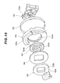
Fig. 14 is a perspective view showing an assembled state of the cam peripheral structure having an intervening member. -
Fig. 15 is an exploded view of the cam peripheral structure inFig. 14 . - The embodiments of the present invention will be described below with reference to the attached drawings. Unless specifically noted, positional relationships in the drawing, such as top, down, left and right, are based on the positional relationships shown in the drawing. The dimensional ratio of the drawing is not limited to the ratio shown in the drawing. Furthermore, the embodiments described below are examples for explaining the present invention and are not intended to limit the present invention only to those embodiments. Various modifications may be made to the present invention without departing from the scope of the invention.
-
Fig. 1 shows an example of an overall configuration of asteering apparatus 1 according to the first embodiment. - The
steering apparatus 1 comprises: arotational axis 10 consisting of, for example, a steering shaft that transmits a steering torque applied by a steering wheel H; a power-assistedmechanism 12 for imparting an auxiliary steering torque to therotational axis 10 by anelectric motor 11; anintermediate shaft 13 connected to an output side of therotational axis 10 imparted with the auxiliary steering torque; atie rod 14 that steers a wheel; a rack-and-pinion steering gear 15 that transmits a steering force of theintermediate shaft 13 to thetie rod 14; and the like. - When a driver rotates the steering wheel H, its rotary force is transmitted to the
rotational axis 10 and theintermediate shaft 13 and is further transmitted to thetie rod 14 via asteering gear 15 to change the steering angle of the wheel. - The power-assisted
mechanism 12 can drive theelectric motor 11 in accordance with the steering torque imparted to therotational axis 10 by the driver so as to impart an auxiliary steering torque to therotational axis 10. - The
steering apparatus 1 according to the present embodiment is capable of adjusting a tilt position (vertical position) and a telescopic position (front/back position) of a steering wheel H by moving acolumn 20 that holds the rotational axis (shaft) 10 of the steering wheel H with respect to a vehicle body. A mechanism for adjusting the tilt position and the telescopic position in thesteering apparatus 1 will be described below. - As shown in
Fig. 2 , for example, thecolumn 20 of thesteering apparatus 1 comprises: a cylindrical lower column (inner column) 40 that internally and rotatably supports therotational axis 10 at theintermediate shaft 13 side (lower steering shaft); and a cylindrical upper column (outer column) 41 that internally and rotatably supports therotational axis 10 at the steering wheel H side (upper steering shaft). - The
upper column 41 is slidably fitted in the outer periphery of thelower column 40 in an axial direction so as to be able to adjust the telescopic position. - The
upper column 41 is supported by abracket 50 fixed to the vehicle body. As shown inFigs. 3 and4 , for example, thebracket 50 includes a pair ofside plates upper column 41 from both sides at the left and the right (vehicle width direction). Theside plates long holes side plates - The upper part of the
upper column 41 is provided with a horizontal pair ofupper plates side plates bracket 50. Theupper plates long holes upper plates - As shown in
Fig. 3 , arod 80 horizontally penetrates through thelong holes side plates bracket 50 and thelong holes upper plates upper column 41, while gripping theupper column 41 between theside plate 60 and theside plate 61 of thebracket 50. - The outer sides at the left and right of the
long holes upper column 41 have larger diameters than the diameters at the inner side, and acylindrical collar 90 through which therod 80 is inserted and acoil spring 91 are fitted in the enlarged diameter portions. The outer side of thecoil spring 91 along therod 80 is provided with aninner sleeve 92. As shown inFig. 5 , theinner sleeve 92 includes aflange part 92a with a large diameter and atubular part 92b, and theflange part 92a contacts thecoil spring 91. - As shown in
Fig. 4 , the outer side (right side inFigs. 3 and4 ) of theside plate 60 of thebracket 50 is provided, along therod 80, with a plurality of annularthin plates 100, a plurality of tiltingfriction plates 101, a plurality oftelescoping friction plates 102, apressing plate 103, athrust bearing 104 and anut 105. The telescopingfriction plate 102 is arranged, for example, between the tiltingfriction plates 101. Furthermore, the annularthin plate 100 is arranged between the tiltingfriction plates 101 and at the inner side of the innermosttilting friction plate 101. - The tilting
friction plate 100 includes a vertically elongatedlong hole 101 a and is clamped by apin 110 provided at theside plate 60 of thebracket 50. The telescopingfriction plate 102 includes along hole 102a elongated in a front/back position and is clamped by apin 111 provided at theupper column 41. As shown inFig. 5B , thetubular part 92b of theinner sleeve 92 is inserted into the holes of the annularthin plates 100, thelong holes 101 a of the tiltingfriction plates 101 and thelong holes 102a of thetelescoping friction plates 102; and the outer end contacts thepressing plate 103. - As shown in
Fig. 4 , the outer side (left side inFigs. 3 and4 ) of theside plate 61 of thebracket 50 is provided, along therod 80, with a plurality of annularthin plates 100, a plurality of tiltingfriction plates 101, a fixedcam 120, amovable cam 121, asleeve 122, apivot lever 123, awasher 130 and anut 131. The annularthin plate 100 is arranged between the tiltingfriction plates 101 and at the inner side of the innermosttilting fiction plate 101. - The tilting
friction plate 101 is clamped by apin 110 provided at theside plate 61 of thebracket 50. As shown inFig. 5A , thetubular part 92b of theinner sleeve 92 is inserted into the holes of the annularthin plates 100 and thelong holes 101 a of the tiltingfriction plates 101; and the outer end contacts the fixedcam 120. - As shown in
Fig. 6 , the fixedcam 120 engages with themovable cam 121 at a cam surface and thesleeve 122 holds the fixedcam 120 and themovable cam 121 from the outer periphery. The outer peripheral surface of thesleeve 122 is provided with aring spring 125 as an annular pressing member. Thepivot lever 123 is clamped at themovable cam 121 and is tightened by thewasher 130 and thenut 131 from the outer side. - The configurations of the fixed
cam 120, themovable cam 121, thesleeve 122, thepivot lever 123 and thering spring 125 will be described below in detail.Fig. 7 is an assembly drawing of these parts andFig. 8 is an exploded view of these parts. - The fixed
cam 120 is formed in a generally square shape and has a cam surface that is axially on the outer side of the rod 80 (surface that contacts the movable cam 121). Themovable cam 121 is formed in a generally disk-shaped shape that has a circular outer peripheral surface and a cam surface at the inner side. The fixedcam 120 and themovable cam 121 have cam surfaces in which ridge parts and notch parts are alternately arranged in a circumferential direction. When themovable cam 121 rotates with respect to the fixedcam 120 and the ridge parts of both cams overlap, the fixedcam 120 is pushed towards the upper column 41 (inner side) along therod 80. On the other hand, when the ridge parts and the notch parts of each of themovable cam 121 and the fixedcam 120 are engaged, the fixedcam 120 returns to the outer side along therod 80. - The
movable cam 121 has arotation regulating part 121 a that protrudes towards, for example, the fixedcam 120, and when themovable cam 121 rotates at a predetermined angle, therotation regulating part 121 a hits thestopper 120a of the fixedcam 120 and is able to control the rotation angle to within a predetermined range. This enables themovable cam 121 to rotate between the position where the ridge parts overlap and the position where the ridge part and the notch part overlap with respect to the fixedcam 120. - The surface of the
movable cam 121 at thepivot lever 123 side is provided with, for example, a square-shaped protrudingpart 121 b. Thepivot lever 123 is formed into an elongated shape which can be easily held by the driver and has a disk-shapedpart 123a at the tip end thereof. The center of the disk-shapedpart 123a is formed with a square-shapedhole 123b. The protrudingpart 121 b of themovable cam 121 is fitted in thehole 123b of thepivot lever 123, and thepivot lever 123 and themovable cam 121 turn integrally. - The
sleeve 122 is formed in a generally ring-shaped shape. As shown inFig. 6 , thesleeve 122 has aninner wall part 122a which matches the outer diameter of themovable cam 121 and theinner wall part 122a slidably receives themovable cam 121. The outer peripheral surface of themovable cam 121 and the inner peripheral surface of theinner wall part 122a of thesleeve 122 are sliding surfaces and grease A is applied to the sliding surfaces. Examples of the grease A may include high-viscosity greases, preferably greases having a small temperature change in kinetic viscosity. - The
ring spring 125 has a diameter that is slightly smaller than that of the outer peripheral surface of thesleeve 122. Thering spring 125 causes thesleeve 122 to be squeezed inwardly and thus be deformed. Thesleeve 122 is pressed against themovable cam 121 at the inner side and thus increases the friction force which is generated at the sliding surfaces between thesleeve 122 and themovable cam 121. - The
sleeve 122 is shaped such that it fits the fixedcam 120. Thesleeve 122 is clamped at the fixedcam 120 in a rotational direction and is locked by the fixedcam 120 so as to be movable in an axial direction. - As shown in
Figs. 6 to 8 , thesleeve 122 has, on the surface at thepivot lever 123 side, a slidingpart 122b that slides, with the disk-shapedpart 123a of thepivot lever 123 being fitted therein. The slidingpart 122b protrudes from the outer periphery of thesleeve 122 towards thepivot lever 123 and includes aconcave groove 122c on the inside, as shown inFig. 6 . The slidingpart 122b and thegroove 122c are formed in an arc-shape along a circumferential direction of thesleeve 122. The disk-shapedpart 123a of thepivot lever 123 is rotatably fitted in thegroove 122c, and thegroove 122c is applied with the grease A. - The
pivot lever 123 is tightened with respect to thesleeve 122 and themovable cam 121 by thewasher 130 and thenut 131. - Next, an operation of a mechanism for adjusting a tilt position and a telescopic position of the steering wheel H configured as set forth above will be described below. When the
pivot lever 123 is turned towards the clamped position (lock) (e.g., upward), themovable cam 121 rotates with respect to the fixedcam 120 and the ridge parts of both cam surfaces overlap, and thereby the fixedcam 120 moves along therod 80 towards the upper column 41 (inner side). When the fixedcam 120 is moved to the inner side, as shown inFig. 5A , the fixedcam 120 pushes the tiltingfriction plate 101, etc. towards the inner side and theside plate 61 of thebracket 50 is thus elastically deformed towards the inner side. - Furthermore, when the fixed
cam 120 is moved to the inner side, therod 80 is pulled towards thepivot lever 123 and thepressing plate 103 moves towards the upper column 41 (inner side). As shown inFig. 5B , this enables thepressing plate 103 to push the tiltingfriction plate 101, etc. towards the inner side and theside plate 60 of thebracket 50 is thus elastically deformed towards the inner side. - As a result, the
upper column 41 is strongly gripped by theside plates bracket 50 and the position of the steering wheel H is fixed. - On the other hand, when the
pivot lever 123 is moved towards the unclamped position (unlock) (e.g., downward), themovable cam 121 rotates with respect to the fixedcam 120 and the ridge part and the notch part of each of the cam surfaces overlap, and thereby the biasing force of thecoil spring 91 causes the fixedcam 120 to be moved towards the pivot lever 123 (outer side). When the fixedcam 120 is moved to the outer side, the tiltingfriction plate 101, etc. which had been pushed by the fixedcam 120 returns to its original position at the outer side, and theside plate 61 of thebracket 50 which had been elastically deformed towards the inner side also returns to its original position. - Furthermore, when the fixed
cam 120 is moved to the outer side, therod 80 moves to the opposite side of thepivot lever 123. This enables thepressing plate 103 which had been pushing the tiltingfriction plate 101, etc. to return to its original position at the outer side, and theside plate 60 of thebracket 50 which had been elastically deformed towards the inner side also returns to its original position. - As a result, the
upper column 41 is released from being gripped by theside plates bracket 50 and is therefore able to move. - When a vertical force is applied to the steering wheel H while the
upper column 41 is released from being gripped by thebracket 50, theupper column 41 moves vertically along thelong holes side plates bracket 50, thereby enabling the tilt position of the steering wheel H to be adjusted. - When a front/back force is applied to the steering wheel H, the
upper column 41 moves frontwards and backwards along thelong holes upper plates upper column 41, thereby enabling the telescopic position of the steering wheel H to be adjusted. - According to the present embodiment, when the
pivot lever 123 is turned to adjust the position of the steering wheel H, themovable cam 121 slides against thesleeve 122. Since thering spring 125 holds the outer peripheral surface of thesleeve 122 and presses thesleeve 122 against themovable cam 121, the friction force of the sliding surfaces between themovable cam 121 and thesleeve 122 is increased. As a result, rattles and rattling sounds which are generated around the cam when the position of the steering wheel H is adjusted are easily and sufficiently reduced. In other words, thering spring 125 serves as a rattle mitigating member which mitigates the rattles and the rattling sounds which are generated around the cam when the position of the steering wheel H is adjusted. Moreover, since thering spring 125 acts on thesleeve 122, the movement of thepivot lever 123 is not affected and the operability of thepivot lever 123 can be sufficiently ensured. - Since the grease A is applied to the sliding surfaces between the
sleeve 122 and themovable cam 121, the grease A can also be used to reduce the rattles and rattling sounds which are generated when the position of the steering wheel H is adjusted. - The
ring spring 125 used as a pressing member is flexible and can be easily assembled with thesleeve 122 and easily be replaced. Furthermore, since thespring ring 125 can also flexibly adjust to the expansion and contraction of thesleeve 122, it can also be appropriately used, for example, in an environment where temperature change is large. - Since an arc-shaped
groove 122c is formed in thesleeve 122 and an outer peripheral part of the disk-shapedpart 123a of thepivot lever 123 is fitted in thegroove 122c to form a sliding part, rattles and rattling sounds can be reduced. Furthermore, since the grease A is applied to the sliding part, rattles and rattling sounds can be further reduced. For example, thepivot lever 123 may vigorously move when the lock is released, but the grease A serves as a damper and the acceleration of thepivot lever 123 can be suppressed. This prevents thepivot lever 123 from severely hitting the driver and the sound from being generated by the movement of thepivot lever 123. - In the above-mentioned embodiment, as shown in
Figs. 9 and10 , a disk-shaped interveningmember 140 may be intervened between thepivot lever 123 and thesleeve 122. In this case, a hole 140a is formed in the center of the interveningmember 140 and aprotruding part 121 b of themovable cam 121 may be fitted in the hole 140a. The interveningmember 140 is fitted in the arc-shapedgroove 122c of thesleeve 122 to form a sliding part. This sliding part causes the rattles and the rattling sounds to be reduced. Furthermore, the grease A may be intervened between thegroove 122c and the interveningmember 140, and in this case, the rattles and the rattling sounds may be further reduced. The operability of thepivot lever 123 can also be sufficiently ensured. - Although preferred embodiments of the present invention have been described above with reference to the attached drawings, the present invention is not limited thereto. As will be appreciated by those skilled in the art, various changes or modifications may be made within the scope of the claims and it will be appreciated that such changes or modifications fall within the technical scope of the invention.
- For example, the configuration of the mechanism for adjusting the tilt position and the telescopic position of the steering wheel H in the above-mentioned embodiment is not limited thereto, and the present invention can also be applied to those having other known telescopic structure configurations. For example, the
pivot lever 123 may have other configurations, as long as it turns the column with respect to the vehicle body in order to clamp and unclamp the column. The configuration of thecams pivot lever 123 into an axial movement of said rotation. - The
sleeve 122 may have other configurations, as long as it holds thecam 120 or thecam 121 and slides against thecam 120 or thecam 121 when thepivot lever 123 is turned. In such a configuration, thering spring 125 may be configured such that thesleeve 122 is pressed against the sliding surfaces of thecams sleeve 122 may be provided with a slit, etc. so as to be easily deformed by thering spring 125. - The pressing member is not limited to being the
spring ring 125 and may be an elastic member with other shapes and materials. The pressing member does not have to be an elastic member and may have other configurations, as long as the sleeve can be pressed against the sliding surface of the cam. The pressing member may be, for example, a threaded ring with a reducible diameter. In the above-mentioned embodiment, the pressing member and the sleeve were separate entities but they may also be integrated. In such configuration, the pressing member and the sleeve may be integrally molded. - Furthermore, the grease A may not be applied to the sliding surfaces between the
sleeve 122 and thecams groove 122c of thesleeve 122 and thepivot lever 123 or the interveningmember 140, and even if applied, the grease A may have low viscosity. In addition, the grease A applied to thegroove 122c may be the same as the grease A applied to the inner peripheral surface (i.e., sliding surface) of theinner wall part 122a of thesleeve 122 described above. It is obvious that the grease A applied to thegroove 122c may be different from the grease A applied to the sliding surface of theinner wall part 122a. - The
steering apparatus 1 does not have to be able to adjust both the tilt position and the telescopic position but may instead adjust either one of such positions. The present invention may also be applied when positions of the steering wheel other than the tilt position and the telescopic position are to be adjusted. Moreover, the clamp position may be lower, or the lower column and the upper column may be switched. - The
steering apparatus 1 according to the second embodiment has a feature wherein a spring clip 125' is provided instead of thering spring 125 according to the first embodiment. Therefore, illustration for the drawings in common with thesteering apparatus 1 according to the first embodiment (Figs. 1-5 ) has been omitted, and the same reference numerals have been provided to the corresponding portions and the detailed description thereof has been omitted. - As shown in
Fig. 11 , the fixedcam 120 engages with themovable cam 121 at a cam surface and thesleeve 122 holds the fixedcam 120 and themovable cam 121 from the outer periphery. The outer peripheral part of thesleeve 122 is provided with a spring clip 125' as a gripping member. Thepivot lever 123 is clamped at themovable cam 121 and is tightened by thewasher 130 and thenut 131 from the outer side. - The configurations of the fixed
cam 120, themovable cam 121, thesleeve 122, thepivot lever 123 and the ring clip 125' will be described below in detail.Fig. 12 is an assembly drawing of these parts andFig. 13 is an exploded view of these parts. - The fixed
cam 120 is formed in a generally square shape and has a cam surface that is axially on the outer side of the rod 80 (surface that contacts the movable cam 121). Themovable cam 121 is formed in a generally disk-shaped shape that has a circular outer peripheral surface and a cam surface at the inner side. The fixedcam 120 and themovable cam 121 have cam surfaces in which ridge parts and notch parts are alternately arranged in a circumferential direction. When themovable cam 121 rotates with respect to the fixedcam 120 and the ridge parts of both cams overlap, the fixedcam 120 is pushed towards the upper column 41 (inner side) along therod 80. On the other hand, when the ridge parts and the notch parts of each of themovable cam 121 and the fixedcam 120 are engaged, the fixedcam 120 returns to the outer side along therod 80. - The
movable cam 121 has arotation regulating part 121 a that protrudes towards, for example, the fixedcam 120, and when themovable cam 121 rotates at a predetermined angle, therotation regulating part 121 a hits thestopper 120a of the fixedcam 120 and is able to control the rotation angle to within a predetermined range. This enables themovable cam 121 to rotate between the position where the ridge parts overlap and the position where the ridge part and the notch part overlap with respect to the fixedcam 120. - The surface of the
movable cam 121 at thepivot lever 123 side is provided with, for example, a square-shaped protrudingpart 121b. Thepivot lever 123 is formed into an elongated shape which can be easily held by the driver and has a disk-shapedpart 123a at the tip end. The center of the disk-shapedpart 123a is formed with a square-shapedhole 123b. The protrudingpart 121b of themovable cam 121 is fitted in thehole 123b of thepivot lever 123, and thepivot lever 123 and themovable cam 121 turn integrally. - The
sleeve 122 is formed in a generally ring-shaped shape. As shown inFig. 11 , thesleeve 122 has aninner wall part 122a which matches the outer diameter of themovable cam 121 and theinner wall part 122a slidably receives themovable cam 121. The outer peripheral surface of themovable cam 121 and the inner peripheral surface of theinner wall part 122a of thesleeve 122 are sliding surfaces and grease A is applied to the sliding surfaces. Examples of the grease A may include high-viscosity greases, preferably greases having a small temperature change in kinetic viscosity. - As shown in
Figs. 11 to 13 , thesleeve 122 has, on the surface at thepivot lever 123 side, a slidingpart 122b that slides, with the disk-shapedpart 123a of thepivot lever 123 being fitted therein. The slidingpart 122b protrudes from the outer periphery of thesleeve 122 towards thepivot lever 123 and includes aconcave groove 122c on the inside, as shown inFig. 11 . The slidingpart 122b and thegroove 122c are formed in an arc-shape along a circumferential direction of thesleeve 122. The disk-shapedpart 123a of thepivot lever 123 is rotatably fitted in thegroove 122c, and thegroove 122c is applied with the grease A. - The spring clip 125' pinches the sliding
part 122b from the outer side. The spring clip 125' has a shorter circumferential length than that of the slidingpart 122b. The spring clip 125' causes the slidingpart 122b of thesleeve 122 to be pressed inwardly and thus be deformed. The slidingpart 122b is pressed against the disk-shapedpart 123a at the inner side and thus increases the friction force which is generated between the disk-shapedpart 123a and the slidingpart 122b. - The
sleeve 122 is shaped such that it fits the fixedcam 120. Thesleeve 122 is clamped at the fixedcam 120 in a rotational direction and is locked by the fixedcam 120 so as to be movable in an axial direction. - The
pivot lever 123 is tightened with respect to thesleeve 122 and themovable cam 121 by thewasher 130 and thenut 131. - The operation of a mechanism for adjusting a tilt position and a telescopic position of the steering wheel H configured as set forth above can be explained as being similar to the above-mentioned first embodiment and will therefore be omitted.
- According to the present embodiment, when the
pivot lever 123 is turned to adjust the position of the steering wheel H, the disk-shapedpart 123a of thepivot lever 123 slides against the slidingpart 122b of thesleeve 122. Since the spring clip 125' grips the slidingpart 122b from the outer side, the friction force between thepivot lever 123 and thesleeve 122 is increased. As a result, rattles and rattling sounds which are generated around the cam when the position of the steering wheel H is adjusted are easily and sufficiently reduced. In other words, the spring clip 125' serves as a rattle mitigating member which mitigates the rattles and the rattling sounds which are generated around the cam when the position of the steering wheel H is adjusted. Moreover, since the spring clip 125' acts on thesleeve 122, the movement of thepivot lever 123 is not affected and the operability of thepivot lever 123 can be sufficiently ensured. - Since grease A is applied to the sliding
part 122b, the grease A can also be used to reduce the rattles and rattling sounds which are generated when the position of the steering wheel H is adjusted. The grease A does not necessarily have to be applied. For example, thepivot lever 123 may vigorously move when the lock is released, but the grease A serves as a damper and the acceleration of thepivot lever 123 can be suppressed. This prevents thepivot lever 123 from severely hitting the driver and prevents sound from being generated by the movement of thepivot lever 123. - The spring clip 125' used as a gripping member is flexible and can be easily assembled with the sliding
part 122b of thesleeve 122 and easily be replaced. Furthermore, since the spring clip 125' can also flexibly adjust to the expansion and contraction of thesleeve 122, it can also be appropriately used, for example, in an environment where temperature change is large. - In the above-mentioned embodiment, as shown in
Figs. 14 and15 , a disk-shaped interveningmember 140 may be intervened between thepivot lever 123 and thesleeve 122. In this case, a hole 140a is formed in the center of the interveningmember 140 and aprotruding part 121 b of themovable cam 121 may be fitted in the hole 140a. The interveningmember 140 is fitted in thegroove 122c of the slidingpart 122b of thesleeve 122. The spring clip 125' is attached to this slidingpart 122b, and rattles and rattling sounds which are generated when the position of the steering wheel H is adjusted can be reduced. Furthermore, the grease A may be intervened between thegroove 122c and the interveningmember 140, and in this case, the rattles and the rattling sounds may be further reduced. The operability of thepivot lever 123 can also be sufficiently ensured. - Although preferred embodiments of the present invention have been described above with reference to the attached drawings, the present invention is not limited thereto. As will be appreciated by those skilled in the art, various changes or modifications may be made within the scope of the claims and it will be appreciated that such changes or modifications fall within the technical scope of the invention.
- For example, the configuration of the mechanism for adjusting the tilt position and the telescopic position of the steering wheel H in the above-mentioned embodiment is not limited thereto, and the present invention can be applied also to those having other known telescopic structure configurations. For example, the
pivot lever 123 may have other configurations, as long as it turns the column with respect to the vehicle body in order to clamp and unclamp the column. The configuration of thecams pivot lever 123 into an axial movement of said rotation. - The
sleeve 122 may have other configurations, as long as it holds thecam 120 or thecam 121 and slides against thecam 120 or thecam 121 when thepivot lever 123 is turned. The configuration of the slidingpart 122b of thesleeve 122 is also not limited thereto. The slidingpart 122b may be provided with a slit, etc. so as to be easily deformed by the spring clip 125'. - The gripping member is not limited to the spring clip 125' and may be an elastic member with other shapes and materials. The gripping member does not have to be an elastic member and may have other configurations, as long as the sliding
part 122b can be held from the outer side and the friction force between thepivot lever 123 or the interveningmember 140 and the slidingpart 122b is increased. The gripping member may be, for example, a clip with a holding function, such as a screw. In the above-mentioned embodiment, the gripping member and the sleeve were separate entities but they may also be integrated. In such configuration, the gripping member and the sleeve may be integrally molded. - Furthermore, the grease A may not be applied to the sliding surfaces between the
sleeve 122 and thecams part 122b of thesleeve 122 and thepivot lever 123 or the interveningmember 140, and even if applied, the grease A may have low viscosity. In addition, the grease A applied to thegroove 122c may be the same as the grease A applied to the inner peripheral surface (i.e., sliding surface) of theinner wall part 122a of thesleeve 122 described above. It is obvious that the grease A applied to thegroove 122c may be different from the grease A applied to the sliding surface of theinner wall part 122a. - The
steering apparatus 1 does not have to be able to adjust both the tilt position and the telescopic position but may instead adjust either one of such positions. The present invention may also be applied when positions of the steering wheel other than the tilt position and the telescopic position are to be adjusted. Moreover, the clamp position may be lower, or the lower column and the upper column may be switched. -
- 1
- steering apparatus
- 10
- rotational axis
- 20
- column
- 40
- lower column
- 41
- upper column
- 50
- bracket
- 80
- rod
- 120
- fixed cam
- 121
- movable cam
- 122
- sleeve
- 123
- pivot lever
- 125
- ring spring
- 125'
- spring clip
- A
- grease
- H
- steering wheel
Claims (13)
- A steering apparatus that is capable of adjusting a position of a steering wheel by moving a column that holds a shaft of the steering wheel with respect to a vehicle body, the steering apparatus comprising:a pivot lever for clamping and unclamping the column with respect to the vehicle body;a cam that clamps and unclamps the column by changing a turn of the pivot lever into an axial movement of said turn;a sleeve that holds the cam and slides against the cam when the pivot lever is turned; anda rattle mitigating member that increases at least any one of friction forces from among a friction force generated between the sleeve and a sliding surface of the cam or a friction force generated between the sleeve and the pivot lever.
- A steering apparatus that is capable of adjusting a position of a steering wheel by moving a column that holds a shaft of the steering wheel with respect to a vehicle body, the steering apparatus comprising:a pivot lever for clamping and unclamping the column with respect to the vehicle body;a cam that clamps and unclamps the column by changing a turn of the pivot lever into an axial movement of said turn;a sleeve that holds the cam and slides against the cam when the pivot lever is turned; anda pressing member that presses the sleeve against a sliding surface of the cam.
- The steering apparatus according to claim 2, wherein the cam includes a movable cam that rotates together with the pivot lever and a fixed cam that moves in the axial direction due to a rotation of the movable cam, wherein the sleeve slides against the movable cam, and wherein the pressing member presses the sleeve against the sliding surface of the movable cam.
- The steering apparatus according to claim 3, wherein the sleeve is formed in an annular shape that receives the movable cam at an inner side, and wherein the pressing member is attached to an outer peripheral surface of the sleeve.
- The steering apparatus according to any one of claims 2 to 4, wherein grease is applied to the sliding surface between the sleeve and the cam.
- The steering apparatus according to any one of claims 2 to 5, wherein the sleeve is provided with a sliding part that slides against the pivot lever or an intervening member intervened between the pivot lever and the sleeve.
- The steering apparatus according to claim 6, wherein the pivot lever or the intervening member has a disk-shaped part, and wherein the sliding part has an arc-shaped groove in which the disk-shaped part is fitted therein.
- The steering apparatus according to claim 6 or 7, wherein the grease is applied to the sliding part.
- The steering apparatus according to any one of claims 2 to 8, wherein the pressing member is an elastic member.
- A steering apparatus that is capable of adjusting a position of a steering wheel by moving a column that holds a shaft of the steering wheel with respect to a vehicle body, the steering apparatus comprising:a pivot lever for clamping and unclamping the column with respect to the vehicle body;a cam that clamps and unclamps the column by changing a turn of the pivot lever into an axial movement of said turn; anda sleeve that holds the cam and slides against the cam when the pivot lever is turned,wherein the sleeve includes a sliding part that slides while a part of the pivot lever or an intervening member intervened between the pivot lever and the sleeve is fitted therein, and
wherein the sliding part is attached with a gripping member that increases a friction force between the sliding part and the pivot lever or the intervening member by pinching the sliding part from the outer side. - The steering apparatus according to claim 10, wherein the pivot lever or the intervening member has a disk-shaped part, and wherein the sliding part is formed in an arc shape along a circumferential direction of the disk-shaped part.
- The steering apparatus according to claim 10 or 11, wherein grease is applied to the sliding part.
- The steering apparatus according to any one of claims 10 to 12, wherein the gripping member is an elastic member.
Applications Claiming Priority (3)
| Application Number | Priority Date | Filing Date | Title |
|---|---|---|---|
| JP2014151917 | 2014-07-25 | ||
| JP2014151916 | 2014-07-25 | ||
| PCT/JP2015/052673 WO2016013235A1 (en) | 2014-07-25 | 2015-01-30 | Steering device |
Publications (3)
| Publication Number | Publication Date |
|---|---|
| EP3085601A1 true EP3085601A1 (en) | 2016-10-26 |
| EP3085601A4 EP3085601A4 (en) | 2017-11-15 |
| EP3085601B1 EP3085601B1 (en) | 2019-01-09 |
Family
ID=55162774
Family Applications (1)
| Application Number | Title | Priority Date | Filing Date |
|---|---|---|---|
| EP15824818.7A Active EP3085601B1 (en) | 2014-07-25 | 2015-01-30 | Steering device |
Country Status (5)
| Country | Link |
|---|---|
| US (1) | US9446780B2 (en) |
| EP (1) | EP3085601B1 (en) |
| JP (1) | JP5958888B2 (en) |
| CN (1) | CN106660573B (en) |
| WO (1) | WO2016013235A1 (en) |
Families Citing this family (5)
| Publication number | Priority date | Publication date | Assignee | Title |
|---|---|---|---|---|
| JP5892302B2 (en) * | 2014-01-30 | 2016-03-23 | 日本精工株式会社 | Steering device |
| EP3075628B1 (en) * | 2014-02-05 | 2019-10-23 | NSK Ltd. | Steering apparatus |
| CN107487352B (en) * | 2016-06-17 | 2019-11-22 | 宝沃汽车(中国)有限公司 | Steering column friction plate group, steering column regulating mechanism and vehicle |
| WO2018209183A1 (en) * | 2017-05-11 | 2018-11-15 | R.H. Sheppard Co., Inc. | Steering column assembly |
| DE102018128119A1 (en) * | 2018-11-09 | 2020-05-14 | Trw Automotive Gmbh | Locking device for an adjustable steering column assembly |
Family Cites Families (15)
| Publication number | Priority date | Publication date | Assignee | Title |
|---|---|---|---|---|
| US20030172765A1 (en) * | 2000-04-20 | 2003-09-18 | Roland Heiml | Adjusting and fixing device for a steering shaft, whose height and/or length can be adjusted |
| US7010996B2 (en) * | 2002-03-08 | 2006-03-14 | Timken Us Corporation | Steering column clamping device |
| WO2005080152A2 (en) * | 2004-02-12 | 2005-09-01 | Huf North America Automotive Parts Mfg. Corp. | Steering lock assembly |
| GB0524980D0 (en) | 2005-12-07 | 2006-01-18 | Nsk Steering Sys Europ Ltd | Adjustment mechanism for a steering column |
| JP2009090894A (en) | 2007-10-10 | 2009-04-30 | Nsk Ltd | Steering device |
| US8677856B2 (en) * | 2010-07-21 | 2014-03-25 | Nsk Ltd. | Steering device |
| EP2617625B1 (en) * | 2010-09-14 | 2016-12-28 | NSK Ltd. | Steering device |
| WO2012035891A1 (en) * | 2010-09-14 | 2012-03-22 | 日本精工株式会社 | Steering device |
| CN102523797B (en) * | 2010-12-31 | 2015-07-15 | 刘闻铎 | Corn directional seeding device |
| DE102011057104B4 (en) * | 2011-12-28 | 2016-03-10 | Thyssenkrupp Presta Aktiengesellschaft | Locking device for an adjustable steering column |
| DE102012102556B3 (en) * | 2012-03-26 | 2013-06-27 | Thyssenkrupp Presta Aktiengesellschaft | Plug-in body for a clamping bolt |
| DE102013107728A1 (en) * | 2013-01-23 | 2014-07-24 | Trw Automotive Gmbh | Clamping device for a longitudinally adjustable and / or height-adjustable steering column of a vehicle |
| JP6350849B2 (en) * | 2014-01-22 | 2018-07-04 | 株式会社ジェイテクト | Steering device |
| EP3075628B1 (en) * | 2014-02-05 | 2019-10-23 | NSK Ltd. | Steering apparatus |
| CN105246762B (en) * | 2014-02-19 | 2017-05-24 | 日本精工株式会社 | Steering device |
-
2015
- 2015-01-30 CN CN201580035280.2A patent/CN106660573B/en active Active
- 2015-01-30 US US14/654,496 patent/US9446780B2/en active Active
- 2015-01-30 JP JP2016518468A patent/JP5958888B2/en active Active
- 2015-01-30 WO PCT/JP2015/052673 patent/WO2016013235A1/en active Application Filing
- 2015-01-30 EP EP15824818.7A patent/EP3085601B1/en active Active
Also Published As
| Publication number | Publication date |
|---|---|
| US20160107675A1 (en) | 2016-04-21 |
| EP3085601A4 (en) | 2017-11-15 |
| JPWO2016013235A1 (en) | 2017-04-27 |
| CN106660573B (en) | 2018-07-31 |
| CN106660573A (en) | 2017-05-10 |
| JP5958888B2 (en) | 2016-08-02 |
| WO2016013235A1 (en) | 2016-01-28 |
| US9446780B2 (en) | 2016-09-20 |
| EP3085601B1 (en) | 2019-01-09 |
Similar Documents
| Publication | Publication Date | Title |
|---|---|---|
| EP3085601B1 (en) | Steering device | |
| KR101031627B1 (en) | Steering column assembly | |
| EP2450254B1 (en) | Steering device | |
| JP5958887B2 (en) | Steering device | |
| EP2923922A2 (en) | Steering Device | |
| JP5293829B2 (en) | Steering device | |
| JP2006069524A (en) | Steering column device | |
| JPWO2004000627A1 (en) | Shock absorbing steering column device for vehicles | |
| JP2010105662A (en) | Steering column device | |
| JP4078893B2 (en) | Shock absorbing steering column device for vehicles | |
| JP2012011837A (en) | Steering column apparatus | |
| US7412911B2 (en) | Steering column apparatus | |
| JP2008105610A (en) | Steering device | |
| JP4457751B2 (en) | Steering column device | |
| KR20180070820A (en) | Steering column | |
| JP5935928B2 (en) | Steering device | |
| JP5229262B2 (en) | Steering device | |
| JP2011093444A (en) | Shock absorbing type steering device | |
| JP5609812B2 (en) | Steering device | |
| KR20150142395A (en) | Steering Column for Vehicle | |
| JP2010285049A (en) | Steering device | |
| JP2009107557A (en) | Electric telescopic arrangement adjusting type steering device | |
| JP6536888B2 (en) | Steering device | |
| JP2009006803A (en) | Steering column device | |
| JP2014196065A (en) | Steering device |
Legal Events
| Date | Code | Title | Description |
|---|---|---|---|
| PUAI | Public reference made under article 153(3) epc to a published international application that has entered the european phase |
Free format text: ORIGINAL CODE: 0009012 |
|
| 17P | Request for examination filed |
Effective date: 20160719 |
|
| AK | Designated contracting states |
Kind code of ref document: A1 Designated state(s): AL AT BE BG CH CY CZ DE DK EE ES FI FR GB GR HR HU IE IS IT LI LT LU LV MC MK MT NL NO PL PT RO RS SE SI SK SM TR |
|
| AX | Request for extension of the european patent |
Extension state: BA ME |
|
| DAX | Request for extension of the european patent (deleted) | ||
| STAA | Information on the status of an ep patent application or granted ep patent |
Free format text: STATUS: EXAMINATION IS IN PROGRESS |
|
| A4 | Supplementary search report drawn up and despatched |
Effective date: 20171017 |
|
| RIC1 | Information provided on ipc code assigned before grant |
Ipc: B62D 1/184 20060101AFI20171011BHEP |
|
| 17Q | First examination report despatched |
Effective date: 20171106 |
|
| GRAP | Despatch of communication of intention to grant a patent |
Free format text: ORIGINAL CODE: EPIDOSNIGR1 |
|
| STAA | Information on the status of an ep patent application or granted ep patent |
Free format text: STATUS: GRANT OF PATENT IS INTENDED |
|
| INTG | Intention to grant announced |
Effective date: 20180719 |
|
| GRAJ | Information related to disapproval of communication of intention to grant by the applicant or resumption of examination proceedings by the epo deleted |
Free format text: ORIGINAL CODE: EPIDOSDIGR1 |
|
| STAA | Information on the status of an ep patent application or granted ep patent |
Free format text: STATUS: EXAMINATION IS IN PROGRESS |
|
| GRAR | Information related to intention to grant a patent recorded |
Free format text: ORIGINAL CODE: EPIDOSNIGR71 |
|
| GRAS | Grant fee paid |
Free format text: ORIGINAL CODE: EPIDOSNIGR3 |
|
| STAA | Information on the status of an ep patent application or granted ep patent |
Free format text: STATUS: GRANT OF PATENT IS INTENDED |
|
| GRAA | (expected) grant |
Free format text: ORIGINAL CODE: 0009210 |
|
| STAA | Information on the status of an ep patent application or granted ep patent |
Free format text: STATUS: THE PATENT HAS BEEN GRANTED |
|
| INTC | Intention to grant announced (deleted) | ||
| AK | Designated contracting states |
Kind code of ref document: B1 Designated state(s): AL AT BE BG CH CY CZ DE DK EE ES FI FR GB GR HR HU IE IS IT LI LT LU LV MC MK MT NL NO PL PT RO RS SE SI SK SM TR |
|
| INTG | Intention to grant announced |
Effective date: 20181203 |
|
| REG | Reference to a national code |
Ref country code: GB Ref legal event code: FG4D |
|
| REG | Reference to a national code |
Ref country code: AT Ref legal event code: REF Ref document number: 1086910 Country of ref document: AT Kind code of ref document: T Effective date: 20190115 Ref country code: CH Ref legal event code: EP |
|
| REG | Reference to a national code |
Ref country code: IE Ref legal event code: FG4D |
|
| REG | Reference to a national code |
Ref country code: DE Ref legal event code: R096 Ref document number: 602015023391 Country of ref document: DE |
|
| REG | Reference to a national code |
Ref country code: NL Ref legal event code: MP Effective date: 20190109 |
|
| REG | Reference to a national code |
Ref country code: LT Ref legal event code: MG4D |
|
| PG25 | Lapsed in a contracting state [announced via postgrant information from national office to epo] |
Ref country code: NL Free format text: LAPSE BECAUSE OF FAILURE TO SUBMIT A TRANSLATION OF THE DESCRIPTION OR TO PAY THE FEE WITHIN THE PRESCRIBED TIME-LIMIT Effective date: 20190109 |
|
| REG | Reference to a national code |
Ref country code: AT Ref legal event code: MK05 Ref document number: 1086910 Country of ref document: AT Kind code of ref document: T Effective date: 20190109 |
|
| PG25 | Lapsed in a contracting state [announced via postgrant information from national office to epo] |
Ref country code: PL Free format text: LAPSE BECAUSE OF FAILURE TO SUBMIT A TRANSLATION OF THE DESCRIPTION OR TO PAY THE FEE WITHIN THE PRESCRIBED TIME-LIMIT Effective date: 20190109 Ref country code: NO Free format text: LAPSE BECAUSE OF FAILURE TO SUBMIT A TRANSLATION OF THE DESCRIPTION OR TO PAY THE FEE WITHIN THE PRESCRIBED TIME-LIMIT Effective date: 20190409 Ref country code: PT Free format text: LAPSE BECAUSE OF FAILURE TO SUBMIT A TRANSLATION OF THE DESCRIPTION OR TO PAY THE FEE WITHIN THE PRESCRIBED TIME-LIMIT Effective date: 20190509 Ref country code: ES Free format text: LAPSE BECAUSE OF FAILURE TO SUBMIT A TRANSLATION OF THE DESCRIPTION OR TO PAY THE FEE WITHIN THE PRESCRIBED TIME-LIMIT Effective date: 20190109 Ref country code: FI Free format text: LAPSE BECAUSE OF FAILURE TO SUBMIT A TRANSLATION OF THE DESCRIPTION OR TO PAY THE FEE WITHIN THE PRESCRIBED TIME-LIMIT Effective date: 20190109 Ref country code: SE Free format text: LAPSE BECAUSE OF FAILURE TO SUBMIT A TRANSLATION OF THE DESCRIPTION OR TO PAY THE FEE WITHIN THE PRESCRIBED TIME-LIMIT Effective date: 20190109 Ref country code: LT Free format text: LAPSE BECAUSE OF FAILURE TO SUBMIT A TRANSLATION OF THE DESCRIPTION OR TO PAY THE FEE WITHIN THE PRESCRIBED TIME-LIMIT Effective date: 20190109 |
|
| PG25 | Lapsed in a contracting state [announced via postgrant information from national office to epo] |
Ref country code: GR Free format text: LAPSE BECAUSE OF FAILURE TO SUBMIT A TRANSLATION OF THE DESCRIPTION OR TO PAY THE FEE WITHIN THE PRESCRIBED TIME-LIMIT Effective date: 20190410 Ref country code: BG Free format text: LAPSE BECAUSE OF FAILURE TO SUBMIT A TRANSLATION OF THE DESCRIPTION OR TO PAY THE FEE WITHIN THE PRESCRIBED TIME-LIMIT Effective date: 20190409 Ref country code: RS Free format text: LAPSE BECAUSE OF FAILURE TO SUBMIT A TRANSLATION OF THE DESCRIPTION OR TO PAY THE FEE WITHIN THE PRESCRIBED TIME-LIMIT Effective date: 20190109 Ref country code: HR Free format text: LAPSE BECAUSE OF FAILURE TO SUBMIT A TRANSLATION OF THE DESCRIPTION OR TO PAY THE FEE WITHIN THE PRESCRIBED TIME-LIMIT Effective date: 20190109 Ref country code: IS Free format text: LAPSE BECAUSE OF FAILURE TO SUBMIT A TRANSLATION OF THE DESCRIPTION OR TO PAY THE FEE WITHIN THE PRESCRIBED TIME-LIMIT Effective date: 20190509 Ref country code: LV Free format text: LAPSE BECAUSE OF FAILURE TO SUBMIT A TRANSLATION OF THE DESCRIPTION OR TO PAY THE FEE WITHIN THE PRESCRIBED TIME-LIMIT Effective date: 20190109 |
|
| REG | Reference to a national code |
Ref country code: CH Ref legal event code: PL |
|
| PG25 | Lapsed in a contracting state [announced via postgrant information from national office to epo] |
Ref country code: LU Free format text: LAPSE BECAUSE OF NON-PAYMENT OF DUE FEES Effective date: 20190130 |
|
| REG | Reference to a national code |
Ref country code: DE Ref legal event code: R097 Ref document number: 602015023391 Country of ref document: DE |
|
| REG | Reference to a national code |
Ref country code: BE Ref legal event code: MM Effective date: 20190131 |
|
| REG | Reference to a national code |
Ref country code: IE Ref legal event code: MM4A |
|
| PG25 | Lapsed in a contracting state [announced via postgrant information from national office to epo] |
Ref country code: SK Free format text: LAPSE BECAUSE OF FAILURE TO SUBMIT A TRANSLATION OF THE DESCRIPTION OR TO PAY THE FEE WITHIN THE PRESCRIBED TIME-LIMIT Effective date: 20190109 Ref country code: DK Free format text: LAPSE BECAUSE OF FAILURE TO SUBMIT A TRANSLATION OF THE DESCRIPTION OR TO PAY THE FEE WITHIN THE PRESCRIBED TIME-LIMIT Effective date: 20190109 Ref country code: IT Free format text: LAPSE BECAUSE OF FAILURE TO SUBMIT A TRANSLATION OF THE DESCRIPTION OR TO PAY THE FEE WITHIN THE PRESCRIBED TIME-LIMIT Effective date: 20190109 Ref country code: EE Free format text: LAPSE BECAUSE OF FAILURE TO SUBMIT A TRANSLATION OF THE DESCRIPTION OR TO PAY THE FEE WITHIN THE PRESCRIBED TIME-LIMIT Effective date: 20190109 Ref country code: CZ Free format text: LAPSE BECAUSE OF FAILURE TO SUBMIT A TRANSLATION OF THE DESCRIPTION OR TO PAY THE FEE WITHIN THE PRESCRIBED TIME-LIMIT Effective date: 20190109 Ref country code: RO Free format text: LAPSE BECAUSE OF FAILURE TO SUBMIT A TRANSLATION OF THE DESCRIPTION OR TO PAY THE FEE WITHIN THE PRESCRIBED TIME-LIMIT Effective date: 20190109 Ref country code: AT Free format text: LAPSE BECAUSE OF FAILURE TO SUBMIT A TRANSLATION OF THE DESCRIPTION OR TO PAY THE FEE WITHIN THE PRESCRIBED TIME-LIMIT Effective date: 20190109 Ref country code: MC Free format text: LAPSE BECAUSE OF FAILURE TO SUBMIT A TRANSLATION OF THE DESCRIPTION OR TO PAY THE FEE WITHIN THE PRESCRIBED TIME-LIMIT Effective date: 20190109 Ref country code: AL Free format text: LAPSE BECAUSE OF FAILURE TO SUBMIT A TRANSLATION OF THE DESCRIPTION OR TO PAY THE FEE WITHIN THE PRESCRIBED TIME-LIMIT Effective date: 20190109 |
|
| PLBE | No opposition filed within time limit |
Free format text: ORIGINAL CODE: 0009261 |
|
| STAA | Information on the status of an ep patent application or granted ep patent |
Free format text: STATUS: NO OPPOSITION FILED WITHIN TIME LIMIT |
|
| PG25 | Lapsed in a contracting state [announced via postgrant information from national office to epo] |
Ref country code: SM Free format text: LAPSE BECAUSE OF FAILURE TO SUBMIT A TRANSLATION OF THE DESCRIPTION OR TO PAY THE FEE WITHIN THE PRESCRIBED TIME-LIMIT Effective date: 20190109 Ref country code: BE Free format text: LAPSE BECAUSE OF NON-PAYMENT OF DUE FEES Effective date: 20190131 |
|
| 26N | No opposition filed |
Effective date: 20191010 |
|
| PG25 | Lapsed in a contracting state [announced via postgrant information from national office to epo] |
Ref country code: LI Free format text: LAPSE BECAUSE OF NON-PAYMENT OF DUE FEES Effective date: 20190131 Ref country code: CH Free format text: LAPSE BECAUSE OF NON-PAYMENT OF DUE FEES Effective date: 20190131 |
|
| PG25 | Lapsed in a contracting state [announced via postgrant information from national office to epo] |
Ref country code: IE Free format text: LAPSE BECAUSE OF NON-PAYMENT OF DUE FEES Effective date: 20190130 |
|
| PG25 | Lapsed in a contracting state [announced via postgrant information from national office to epo] |
Ref country code: SI Free format text: LAPSE BECAUSE OF FAILURE TO SUBMIT A TRANSLATION OF THE DESCRIPTION OR TO PAY THE FEE WITHIN THE PRESCRIBED TIME-LIMIT Effective date: 20190109 |
|
| PGFP | Annual fee paid to national office [announced via postgrant information from national office to epo] |
Ref country code: FR Payment date: 20191216 Year of fee payment: 6 |
|
| PG25 | Lapsed in a contracting state [announced via postgrant information from national office to epo] |
Ref country code: TR Free format text: LAPSE BECAUSE OF FAILURE TO SUBMIT A TRANSLATION OF THE DESCRIPTION OR TO PAY THE FEE WITHIN THE PRESCRIBED TIME-LIMIT Effective date: 20190109 |
|
| PGFP | Annual fee paid to national office [announced via postgrant information from national office to epo] |
Ref country code: GB Payment date: 20200122 Year of fee payment: 6 |
|
| PG25 | Lapsed in a contracting state [announced via postgrant information from national office to epo] |
Ref country code: MT Free format text: LAPSE BECAUSE OF NON-PAYMENT OF DUE FEES Effective date: 20190130 |
|
| PG25 | Lapsed in a contracting state [announced via postgrant information from national office to epo] |
Ref country code: CY Free format text: LAPSE BECAUSE OF FAILURE TO SUBMIT A TRANSLATION OF THE DESCRIPTION OR TO PAY THE FEE WITHIN THE PRESCRIBED TIME-LIMIT Effective date: 20190109 |
|
| PG25 | Lapsed in a contracting state [announced via postgrant information from national office to epo] |
Ref country code: HU Free format text: LAPSE BECAUSE OF FAILURE TO SUBMIT A TRANSLATION OF THE DESCRIPTION OR TO PAY THE FEE WITHIN THE PRESCRIBED TIME-LIMIT; INVALID AB INITIO Effective date: 20150130 |
|
| GBPC | Gb: european patent ceased through non-payment of renewal fee |
Effective date: 20210130 |
|
| PG25 | Lapsed in a contracting state [announced via postgrant information from national office to epo] |
Ref country code: FR Free format text: LAPSE BECAUSE OF NON-PAYMENT OF DUE FEES Effective date: 20210131 |
|
| PG25 | Lapsed in a contracting state [announced via postgrant information from national office to epo] |
Ref country code: GB Free format text: LAPSE BECAUSE OF NON-PAYMENT OF DUE FEES Effective date: 20210130 |
|
| PG25 | Lapsed in a contracting state [announced via postgrant information from national office to epo] |
Ref country code: MK Free format text: LAPSE BECAUSE OF FAILURE TO SUBMIT A TRANSLATION OF THE DESCRIPTION OR TO PAY THE FEE WITHIN THE PRESCRIBED TIME-LIMIT Effective date: 20190109 |
|
| PGFP | Annual fee paid to national office [announced via postgrant information from national office to epo] |
Ref country code: DE Payment date: 20221207 Year of fee payment: 9 |