EP2923922A2 - Steering Device - Google Patents
Steering Device Download PDFInfo
- Publication number
- EP2923922A2 EP2923922A2 EP15160370.1A EP15160370A EP2923922A2 EP 2923922 A2 EP2923922 A2 EP 2923922A2 EP 15160370 A EP15160370 A EP 15160370A EP 2923922 A2 EP2923922 A2 EP 2923922A2
- Authority
- EP
- European Patent Office
- Prior art keywords
- shaft
- jacket
- steering
- lock
- lock member
- Prior art date
- Legal status (The legal status is an assumption and is not a legal conclusion. Google has not performed a legal analysis and makes no representation as to the accuracy of the status listed.)
- Granted
Links
- 238000010521 absorption reaction Methods 0.000 description 16
- 238000005192 partition Methods 0.000 description 11
- 230000007246 mechanism Effects 0.000 description 9
- 230000002093 peripheral effect Effects 0.000 description 9
- 238000003780 insertion Methods 0.000 description 5
- 230000037431 insertion Effects 0.000 description 5
- 230000008878 coupling Effects 0.000 description 4
- 238000010168 coupling process Methods 0.000 description 4
- 238000005859 coupling reaction Methods 0.000 description 4
- 230000008602 contraction Effects 0.000 description 3
- 238000000926 separation method Methods 0.000 description 2
- 239000007787 solid Substances 0.000 description 2
- 238000003466 welding Methods 0.000 description 2
- 238000005452 bending Methods 0.000 description 1
- 230000005540 biological transmission Effects 0.000 description 1
- 230000015572 biosynthetic process Effects 0.000 description 1
- 230000002265 prevention Effects 0.000 description 1
- 239000011347 resin Substances 0.000 description 1
- 229920005989 resin Polymers 0.000 description 1
- 230000004044 response Effects 0.000 description 1
Images


Classifications
-
- B—PERFORMING OPERATIONS; TRANSPORTING
- B62—LAND VEHICLES FOR TRAVELLING OTHERWISE THAN ON RAILS
- B62D—MOTOR VEHICLES; TRAILERS
- B62D1/00—Steering controls, i.e. means for initiating a change of direction of the vehicle
- B62D1/02—Steering controls, i.e. means for initiating a change of direction of the vehicle vehicle-mounted
- B62D1/16—Steering columns
- B62D1/18—Steering columns yieldable or adjustable, e.g. tiltable
- B62D1/19—Steering columns yieldable or adjustable, e.g. tiltable incorporating energy-absorbing arrangements, e.g. by being yieldable or collapsible
- B62D1/195—Yieldable supports for the steering column
-
- B—PERFORMING OPERATIONS; TRANSPORTING
- B62—LAND VEHICLES FOR TRAVELLING OTHERWISE THAN ON RAILS
- B62D—MOTOR VEHICLES; TRAILERS
- B62D1/00—Steering controls, i.e. means for initiating a change of direction of the vehicle
- B62D1/02—Steering controls, i.e. means for initiating a change of direction of the vehicle vehicle-mounted
- B62D1/16—Steering columns
- B62D1/18—Steering columns yieldable or adjustable, e.g. tiltable
- B62D1/184—Mechanisms for locking columns at selected positions
-
- B—PERFORMING OPERATIONS; TRANSPORTING
- B62—LAND VEHICLES FOR TRAVELLING OTHERWISE THAN ON RAILS
- B62D—MOTOR VEHICLES; TRAILERS
- B62D1/00—Steering controls, i.e. means for initiating a change of direction of the vehicle
- B62D1/02—Steering controls, i.e. means for initiating a change of direction of the vehicle vehicle-mounted
- B62D1/16—Steering columns
- B62D1/18—Steering columns yieldable or adjustable, e.g. tiltable
- B62D1/187—Steering columns yieldable or adjustable, e.g. tiltable with tilt adjustment; with tilt and axial adjustment
- B62D1/189—Steering columns yieldable or adjustable, e.g. tiltable with tilt adjustment; with tilt and axial adjustment the entire column being tiltable as a unit
-
- B—PERFORMING OPERATIONS; TRANSPORTING
- B62—LAND VEHICLES FOR TRAVELLING OTHERWISE THAN ON RAILS
- B62D—MOTOR VEHICLES; TRAILERS
- B62D1/00—Steering controls, i.e. means for initiating a change of direction of the vehicle
- B62D1/02—Steering controls, i.e. means for initiating a change of direction of the vehicle vehicle-mounted
- B62D1/16—Steering columns
- B62D1/18—Steering columns yieldable or adjustable, e.g. tiltable
- B62D1/19—Steering columns yieldable or adjustable, e.g. tiltable incorporating energy-absorbing arrangements, e.g. by being yieldable or collapsible
Definitions
- the invention relates to a steering device.
- a steering shaft to which a steering wheel is mounted is rotatably supported by an adjustment unit supported by a support unit.
- the adjustment unit is moved in an axial direction of the steering shaft, it is possible to adjust the position of the steering wheel in the axial direction.
- the adjustment unit is disposed between a pair of side plates in the support unit. Each side plate is provided with a hole, and a clamping bolt is inserted into the hole. A lock member is attached to the clamping bolt, and an operation lever is coupled to the clamping bolt. To the adjustment unit, an opposite lock member having a large number of notches is coupled via a breakaway plate.
- the breakaway plate In the steering column described in JP-A-2011-516323 , the breakaway plate needs to be additionally provided in order to absorb the energy at the time of the vehicle collision, and hence an increase in the number of components is inevitable. Further, in order to obtain desired characteristics of energy absorption at the time of the vehicle collision, fine adjustment is required such that the breakaway plate is properly deformed.
- the invention provides the steering device capable of obtaining desired characteristics of the energy absorption at the time of the vehicle collision while preventing the increase in the number of components.
- An aspect of the invention is a steering device including: a steering shaft including a first end to which a steering member is mounted and a second end, wherein the steering shaft is telescopically adjustable in an axial direction of the steering shaft; a column jacket rotatably supporting the steering shaft and including an upper jacket positioned on a first end side and a lower jacket positioned on a second end side, wherein the column jacket is telescopically adjustable together with the steering shaft with movement of the upper jacket relative to the lower jacket in the axial direction; a lock plate fixed to the upper jacket and provided with a plurality of holes arranged in the axial direction; a support bracket fixed to a vehicle body and supporting the column jacket; an operation member supported by the support bracket, wherein the operation member is operated when the steering shaft and the column jacket are telescopically adjusted; a support shaft that is supported by the lower jacket, extends in a cross direction crossing the axial direction, and includes a low-strength portion to be broken when a load acts on the steering shaft and the
- the low-strength portion in the support shaft originally serving as a component for supporting the lock member Only by providing the low-strength portion in the support shaft originally serving as a component for supporting the lock member, it is possible to absorb the energy at the time of the vehicle collision without adding a new component. Further, only by adjusting a breakage load of the support shaft by changing the size of the low-strength portion, it is possible to arbitrarily adjust characteristics of energy absorption at the time of the vehicle collision.
- the support shaft may include a first shaft portion that extends in the cross direction and a second shaft portion that is thicker than the first shaft portion, and the low-strength portion may include a boundary portion between the first shaft portion and the second shaft portion.
- the low-strength portion includes the boundary portion between the first shaft portion and the second shaft portion that is thicker than the first shaft portion in the support shaft, only by adjusting the breakage load of the support shaft by adjusting a difference in thickness between the first shaft portion and the second shaft portion, it is possible to obtain desired characteristics of the energy absorption at the time of the vehicle collision.
- the steering device may further include a biasing component that biases the support shaft such that a gap between the lock member and the boundary portion in the cross direction is reduced.
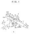
- FIG. 1 is a schematic perspective view of a steering device 1 according to an embodiment of the invention.
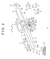
- FIG. 2 is a schematic side view showing the schematic configuration of the steering device 1.
- the left side on the paper sheet corresponds to the front side of a vehicle body 2 to which the steering device 1 is mounted
- the right side on the paper sheet corresponds to the rear side of the vehicle body 2
- the upper side on the paper sheet corresponds to the upper side of the vehicle body 2
- the lower side on the paper sheet corresponds to the lower side of the vehicle body 2.
- the steering device 1 mainly includes a steering shaft 3, a column jacket 4, a lower bracket 5, an upper bracket 6 as a support bracket, and a lock mechanism 7.
- a steering member 8 is mounted to a first end 3A on the rear side, and a second end 3B on the front side is coupled to a steering mechanism 13 via a universal joint 9, an intermediate shaft 10, a universal joint 11, and a pinion shaft 12.
- the steering mechanism 13 is constituted by a rack and pinion mechanism and the like. The steering mechanism 13 steers a turning wheel such as a tire that is not shown in response to transmission of rotation of the steering shaft 3.
- the steering shaft 3 has a substantially cylindrical or columnar shape that extends in a front-rear direction of the vehicle body 2 as a whole.
- the direction in which the steering shaft 3 extends is assumed to be an axial direction X.
- the axial direction X in the embodiment is inclined relative to a horizontal direction such that the second end 3B is lower than the first end 3A.
- the rear side as the first end side (the side where the steering member 8 is positioned) in the axial direction X is designated by a reference numeral "X1", while the front side as the second end side (the side opposite to the side where the steering member 8 is positioned) in the axial direction X is designated by a reference numeral "X2".
- the rear side X1 corresponds to the rear side of the vehicle body 2
- the front side X2 corresponds to the front side of the vehicle body 2.
- a direction perpendicular to the paper sheet in FIG. 2 is referred to as a right-left direction Y
- a direction extending substantially vertically in FIG. 2 is referred to as an up-down direction Z.
- the right-left direction Y and the up-down direction Z may not be orthogonal to the axial direction X strictly.
- the far side on the paper sheet in FIG. 2 is a right side Y1
- the near side on the paper sheet is a left side Y2.
- the upper side in the up-down direction Z is designated by a reference numeral "Z1”
- the lower side in the up-down direction Z is designated by a reference numeral "Z2".
- the steering shaft 3 includes a cylindrical or columnar upper shaft 14 and a cylindrical or columnar lower shaft 15.
- the upper shaft 14 is disposed on the rear side X1 of the lower shaft 15.
- the upper shaft 14 and the lower shaft 15 are concentrically arranged.
- An end portion of the upper shaft 14 on the rear side X1 corresponds to the first end 3A of the steering shaft 3, and the steering member 8 is coupled to the end portion of the upper shaft 14 on the rear side X1.
- the upper shaft 14 at least an end portion on the front side X2 is formed in a cylindrical shape.
- an end portion of the lower shaft 15 on the rear side X1 is inserted from the front side X2.
- the upper shaft 14 and the lower shaft 15 are fitted to each other by spline fitting or serration fitting. Accordingly, the upper shaft 14 and the lower shaft 15 can rotate together integrally, and can move relative to each other along the axial direction X. Therefore, the steering shaft 3 is telescopically adjustable (the steering shaft 3 can extend or contract) in the axial direction X.
- the column jacket 4 is a hollow body that extends in the axial direction X as a whole.
- the steering shaft 3 is accommodated in the column jacket 4.
- the column jacket 4 has a substantially tubular upper jacket 16 and a substantially tubular lower jacket 17 that extend in the axial direction X.
- the upper jacket 16 is positioned on the rear side X1 of the lower jacket 17.
- the lower jacket 17 is positioned on the front side X2 of the upper jacket 16.
- the lower jacket 17 is thicker than the upper jacket 16, and is fitted on the upper jacket 16.
- an end portion 16A of the upper jacket 16 on the front side X2 is inserted into an end portion 17A of the lower jacket 17 on the rear side X1 from the rear side X1.
- the upper jacket 16 can move relative to the lower jacket 17 in the axial direction X.
- the column jacket 4 is telescopically adjustable in the axial direction X.
- the steering shaft 3 is coupled to the column jacket 4 via a bearing that is not shown, and hence the column jacket 4 rotatably supports the steering shaft 3.
- the upper shaft 14 and the upper jacket 16 are coupled to each other via a bearing that is not shown.
- the lower shaft 15 and the lower jacket 17 are coupled to each other via a bearing that is not shown. Accordingly, the coupled body of the upper shaft 14 and the upper jacket 16 can move relative to the lower shaft 15 and the lower jacket 17 in the axial direction X.
- the column jacket 4 is telescopically adjustable together with the steering shaft 3.
- the positional adjustment of the steering member 8 in the axial direction X by extension or contraction of the steering shaft 3 and the column jacket 4 is called a telescopic adjustment.
- the lower bracket 5 supports the portion of the column jacket 4 on the front side X2, and couples the steering device 1 to the vehicle body 2. Specifically, the lower bracket 5 supports the portion of the lower jacket 17 on the front side X2.
- the lower bracket 5 includes a movable bracket 18 fixed to the lower jacket 17, a fixed bracket 19 fixed to the vehicle body 2, and a central shaft 20 extending in the right-left direction Y.
- a pair of the right and left movable brackets 18 are provided on, e.g., an upper outer peripheral surface of an end portion 17B of the lower jacket 17 on the front side X2 (see FIG. 1 ).
- the movable bracket 18 is tiltably supported by the fixed bracket 19 via the central shaft 20.
- the entire column jacket 4 can tilt vertically about the central shaft 20 together with the steering shaft 3.
- An orientation adjustment of the steering member 8 by the tilt is called a tilt adjustment.
- the lower jacket 17 is coupled to the fixed bracket 19 fixed to the vehicle body 2 via the central shaft 20, and hence the lower jacket 17 can tilt but cannot move in the axial direction X.
- the upper bracket 6 supports the portion of the column jacket 4 on the rear side X1 of the movable bracket 18. Specifically, the upper bracket 6 supports the portion of the lower jacket 17 on the rear side X1.
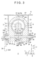
- FIG. 3 is a schematic cross-sectional view of the steering device 1 taken along the line III-III of FIG. 2 .
- the upper bracket 6 has a groove shape that is opened downward, and is formed to be bilaterally symmetric with respect to the column jacket 4 so as to have a substantially U-shape that is vertically inverted when viewed from the axial direction X.
- the upper bracket 6 integrally includes a pair of side plates 21 that oppose each other with the column jacket 4 interposed therebetween and a coupling plate 22 that is coupled to the upper end portions of the pair of the side plates 21.
- the side plate 21 is thin in the right-left direction Y, and the coupling plate 22 is thin in the up-down direction Z.
- tilt elongated holes 23 are formed at the same positions when viewed from the right-left direction Y.
- the tilt elongated hole 23 extends in the up-down direction Z or, to be precise, in a tilt direction as a circumferential direction with the central shaft 20 (see FIG. 2 ) serving as the center.
- the coupling plate 22 has extending portions that extend outward in the right-left direction Y beyond the pair of the side plates 21, and the entire upper bracket 6 is fixed to the vehicle body 2 using bolts (not shown) or the like that are inserted into the extending portions.
- a slit 24 as a cut-out that extends in the axial direction X is formed (see also FIG. 1 ).
- the slit 24 is opened to both of the rear side X1 and the lower side Z2 from the end portion 17A toward the outside of the lower jacket 17 (see also FIG. 1 ).
- the end portion 17A of the lower jacket 17 has a vertically inverted substantially U-shaped cross section.
- each support portion 25 has a substantially rectangular solid shape that spreads in the axial direction X and the up-down direction Z.
- through holes 26 that pass through the support portions 25 in the right-left direction Y are formed at the same positions when viewed from the right-left direction Y.
- the steering device 1 includes a clamping shaft 27 that is inserted into a portion where the through hole 26 and the tilt elongated hole 23 overlap each other when viewed from the right-left direction Y.
- the clamping shaft 27 has a substantially columnar shape that extends in the right-left direction Y. Both ends of the clamping shaft 27 in the right-left direction Y protrude outward in the right-left direction Y from the pair of the side plates 21 of the upper bracket 6.
- a head portion 29 having a diameter larger than that of the clamping shaft 27 is formed.
- a grippable lever-type operation member 30 that is operated for the telescopic adjustment and the tilt adjustment, an annular cam 31, and a cam follower 32 are arranged in this order from the left side Y2.
- the clamping shaft 27 is inserted into a base end portion 30A of the operation member 30 on one end side in a longitudinal direction, the cam 31, and the cam follower 32. Since the clamping shaft 27 is inserted into each tilt elongated hole 23 of the upper bracket 6, the operation member 30, the cam 31, and the cam follower 32 are supported by the upper bracket 6 via the clamping shaft 27.
- the operation member 30 and the cam 31 can rotate integrally with each other relative to the clamping shaft 27, while the cam follower 32 can rotate relative to the clamping shaft 27 and can move in the right-left direction Y.
- a portion of the cam follower 32 that is inserted into the tilt elongated hole 23 of the side plate 21 on the left side Y2 is formed with two opposing surfaces, and hence the slipping of the cam follower 32 is prevented by the tilt elongated hole 23.
- a nut 33 is attached to the end portion of the clamping shaft 27 on the right side Y1. Between the nut 33 and the side plate 21 on the right side, an interposed member 34, a needle roller bearing 35, and a thrust washer 36 are arranged in this order from the left side Y2. The clamping shaft 27 is inserted into the interposed member 34, the needle roller bearing 35, and the thrust washer 36.
- the clamping shaft 27 can move in the above-described tilt direction in each tilt elongated hole 23 of the upper bracket 6.
- a use such as a driver moves the steering member 8 in the up-down direction Z for the tilt adjustment, the entire column jacket 4 tilts relative to the upper bracket 6 as described above.
- the tilt adjustment of the steering member 8 is performed within a range in which the clamping shaft 27 can move in the tilt elongated hole 23.
- the pair of the side plates 21 holds the support portions 25 of the lower jacket 17 between them from both sides in the right-left direction Y, and a frictional force is thereby generated between each side plate 21 and the support portion 25.
- the position of the column jacket 4 is locked, and the steering member 8 is locked at the position after the tilt adjustment and is prevented from moving in the tilt direction.
- the pair of the support portions 25 of the lower jacket 17 is held between the side plates 21, and the distance between the pair of the support portions 25 is reduced so that the inner portion of the lower jacket 17 is narrowed, and the lower jacket 17 comes in pressure contact with the upper jacket 16 in the lower jacket 17.
- the state of the steering device 1 when the position of the steering member 8 is fixed in each of the tilt direction and the axial direction X is called a "locked state".
- the lock mechanism 7 is a mechanism for firmly locking the upper jacket 16 such that the upper jacket 16 does not move in the axial direction X in the steering device 1 in the locked state, and is provided in the vicinity of the central portion of the clamping shaft 27 in the right-left direction Y.
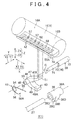
- FIG. 4 is an exploded perspective view of the principal portion of the steering device 1.
- the upper jacket 16 is represented by using a two-dot chain line.
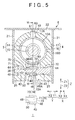
- FIG. 5 is a schematic cross-sectional view of the steering device 1 taken along the line V-V of FIG. 2 .
- FIG. 6 is a schematic sectional view of the steering device 1 taken long the line VI-VI of FIG. 5 .
- the depiction of the steering shaft 3 is omitted (the same applies to FIG. 7 described later).
- the lock mechanism 7 includes a cam 38, a support shaft 39, a lock member 40, a biasing member 41, and a lock plate 42.
- the cam 38 integrally includes a cylindrical boss portion 38A that extends in the right-left direction Y, and a cam portion 38B that protrudes outward in the radial direction of the boss portion 38A from one position on the periphery of the boss portion 38A.
- the cam portion 38B has a substantially triangular shape that is tapered with approach to the outside in the radial direction of the boss portion 38A when viewed from the right-left direction Y.
- the outer tip portion of the cam portion 38B in the radial direction is designated by a reference numeral "38C".
- the cam portion 38B has a pair of arc-shaped surfaces 38D that connect the tip portion 38C and the outer peripheral surface of the boss portion 38A and are smoothly coupled to each other on the outer peripheral surface of the boss portion 38A.
- the cam 38 is disposed in the slit 24 of the lower jacket 17, and the portion of the clamping shaft 27 exposed in the slit 24 between the pair of the support portions 25 is inserted into the boss portion 38A (see also FIG. 3 ).
- the boss portion 38A and the clamping shaft 27 are fitted to each other by spline fitting or the like. Accordingly, the cam 38 can rotate integrally with the clamping shaft 27 in accordance with the operation of the operation member 30.
- the support shaft 39 has a columnar shape that extends in the right-left direction Y as a cross direction to the axial direction X.
- the support shaft 39 is made of a resin.
- the support shaft 39 integrally includes a first shaft portion 71 that extends in the right-left direction Y, and a second shaft portion 72 that is thicker than the first shaft portion 71.
- Each of the first shaft portion 71 and the second shaft portion 72 has a columnar shape that extends in the right-left direction.
- the diameter of the second shaft portion 72 is larger than that of the first shaft portion 71.
- the second shaft portion 72 is coaxially coupled to the first shaft portion 71 from the right side Y1.
- a boundary portion 73 between the first shaft portion 71 and the second shaft portion 72 serves as a low-strength portion 74 of which the strength is locally lowed.
- round through holes 43 that pass through the support portions 25 in the right-left direction Y are formed at positions on the front side X2 of the through holes 26.
- the inner diameter of the through hole 43 of the support portion 25 on the left side Y2 is substantially the same as the diameter of the first shaft portion 71
- the inner diameter of the through hole 43 of the support portion 25 on the right side Y1 is substantially the same as the diameter of the second shaft portion 72.
- the through hole 43 includes an increased diameter portion 44 of which the diameter is increased on the outside in the right-left direction Y.
- the support shaft 39 is inserted into the through holes 43 of the individual support portions 25.
- the first shaft portion 71 is inserted into the through hole 43 of the support portion 25 on the left side Y2, and the second shaft portion 72 is inserted into the through hole 43 of the support portion 25 on the right side Y1.
- the support shaft 39 is supported by the lower jacket 17 by being inserted into the through holes 43, and can rotate in a circumferential direction C of the support shaft 39 (see FIG. 4 ).
- the boundary portion 73 (the low-strength portion 74) between the first shaft portion 71 and the second shaft portion 72 is positioned in the slit 24 between the right and left support portions 25.
- Both end portions of the support shaft 39 in the right-left direction Y reach the increased diameter portions 44, and oppose the side plates 21 of the upper bracket 6 from the inside in the right-left direction Y with gaps interposed between the both end portions and the side plates 21.
- a push nut 45 as a biasing component included in the steering device 1 is attached to one of the end portions of the support shaft 39 in the right-left direction Y.
- the push nut 45 is fitted on the end portion of the support shaft 39 on the left side Y2 in the increased diameter portion 44 of the support portion 25 on the left side Y2.
- the support shaft 39 is biased to the left side Y2 by the push nut 45.
- the lock member 40 has a substantially V-shape that is inclined by 90° to the rear side X1 when viewed from the right-left direction Y.
- the lock member 40 is a sintered component that integrally includes a base end portion 46, and a lock portion 47 and a contact portion 48 that extend from the base end portion 46 to the rear side X1.
- the base end portion 46 is a coupling portion of the lock portion 47 and the contact portion 48.
- the base end portion 46 is formed with an insertion hole 49 that passes through the base end portion 46 in the right-left direction Y.
- One cylindrical portion 50 that protrudes to the left side Y2 while surrounding the insertion hole 49 is formed on the side surface of the base end portion 46 on the left side Y2.
- the cylindrical portion 50 is considered to be a part of the base end portion 46.
- the lock portion 47 has a shape that extends from the base end portion 46 to the rear side X1 and the upper side Z1.
- the end portion of the lock portion 47 on the rear side X1 serves as a tooth 51, and the tooth 51 is bent toward the upper side Z1.
- the contact portion 48 has a shape that extends from the base end portion 46 to the rear side X1.
- the contact portion 48 is positioned on the lower side Z2 of the lock portion 47.
- the above-described lock member 40 is disposed on the front side X2 of the cam 38 in the slit 24 of the lower jacket 17 (see also FIG. 6 ).
- the portion of the support shaft 39 described above positioned in the slit 24 is inserted into the insertion hole 49 of the base end portion 46 of the lock member 40.
- the portion of the first shaft portion 71 of the support shaft 39 positioned in the slit 24 is inserted into the insertion hole 49 of the base end portion 46 of the lock member 40.
- the second shaft portion 72 of the support shaft 39 is positioned on the right side Y1 of the base end portion 46.
- the push nut 45 biases the support shaft 39 to the left side Y2, whereby the boundary portion 73 between the first shaft portion 71 and the second shaft portion 72 of the support shaft 39, i.e., a side surface 72A of the second shaft portion 72 on the left side Y2 comes in surface contact with a side surface 46A of the base end portion 46 on the right side Y1 from the right side Y1, and biases the base end portion 46 to the left side Y2. That is, the push nut 45 biases the support shaft 39 such that a gap between the lock member 40 and the boundary portion 73 in the right-left direction Y is reduced or eliminated.
- the side surface 72A of the second shaft portion 72 biases the base end portion 46 to the left side Y2, and hence the cylindrical portion 50 positioned on the left side Y2 in the base end portion 46 comes in contact with the support portion 25 on the left side Y2 from the right side Y1.
- the entire base end portion 46 including the cylindrical portion 50 is sandwiched between the support portion 25 on the left side Y2 and the boundary portion 73 of the support shaft 39 in the right-left direction Y without any gap.
- the support shaft 39 and the base end portion 46 are fitted to each other so as to be integrally rotatable or rotatable relative to each other by lightly press-fitting or the like. Accordingly, the lock member 40 can rotate in the circumferential direction C about the center of the support shaft 39 (see FIG. 4 ) together with the support shaft 39.
- the support shaft 39 is inserted into the through hole 43 of each support portion 25 of the lower jacket 17, whereby the lock member 40 is rotatably supported by the support shaft 39, and is also supported by the lower jacket 17 via the support shaft 39.
- the above-described cam 38 is disposed between the lock portion 47 and the contact portion 48 of the lock member 40, and the cam portion 38B of the cam 38 comes in contact with an upper surface 48A of the contact portion 48 from the upper side Z1 (see FIG. 6 ).
- the biasing member 41 is a spring formed by bending a wire or the like.
- the biasing member 41 integrally includes a coil-shaped portion 54 that is wound around the outer peripheral surface of the cylindrical portion 50 of the base end portion 46 on the left side Y2 from the outside, and a holding portion 55 and a deformed portion 56 that extend from the coil-shaped portion 54 to the rear side X1.
- the deformed portion 56 is disposed on the lower side Z2 of the holding portion 55.
- An end portion 56A of the deformed portion 56 on the rear side X1 is bent to the right side Y1.
- the holding portion 55 engages the outer peripheral surface of the portion of the boss portion 38A of the cam 38 on the left side Y2 of the cam portion 38B from the upper side Z1, and the end portion 56A of the deformed portion 56 engages the contact portion 48 of the lock member 40 from the lower side Z2 (see FIG. 6 ).
- a force that moves the deformed portion 56 toward the holding portion 55 to the upper side Z1 is generated, and this force serves as a biasing force for biasing the entire lock member 40 to the upper side Z1 along the circumferential direction C.
- the lock plate 42 has a plate shape that is long in the axial direction X and is thick in the up-down direction Z, and is curved along an outer peripheral surface 16B of the upper jacket 16.
- the lock plate 42 is disposed at the portion of the underside of the outer peripheral surface 16B of the upper jacket 16 that is exposed to the slit 24 of the lower jacket 17 (see FIGS. 3 and 5 ).
- the lock plate 42 is fixed to the upper jacket 16 by welding or the like. Accordingly, the lock plate 42 can move relative to the lower jacket 17 in the axial direction X together with the upper jacket 16.
- the lock plate 42 is positioned on the upper side Z1 of the lock member 40 or, to be precise, immediately above the lock member 40. Accordingly, the tooth 51 of the lock member 40 that is biased to the upper side Z1 by the biasing member 41 is biased toward the lock plate 42.
- a plurality of holes 57 that extend along the circumferential direction of the outer peripheral surface 16B of the upper jacket 16 are formed so as to be arranged in the axial direction X.
- the number of holes 57 is nine in the embodiment, but the number thereof is not limited thereto.
- Each hole 57 passes through the lock plate 42 in the up-down direction Z as the direction of thickness of the lock plate 42.
- Partition portions 58 are provided in the lock plate 42 so as to correspond to the plurality of the holes 57 on a one-to-one basis.
- the partition portion 58 is adjacent to the rear side X1 of the hole 57.
- the number of provided partition portions 58 is equal to the number of holes 57, and a plurality of the partition portions 58 are arranged in the axial direction X.
- the partition portion 58 other than the rearmost partition portion 58 closest to the steering member 8 forms a boundary portion between two holes 57 adjacent to each other in the axial direction X.
- the end portion of the rearmost partition portion 58A on the rear side X1 constitutes a stopper 70 that is bent to the lower side Z2.
- the cam portion 38B of the cam 38 is directed to the front side X2, and the arc-shaped surface 38D of the cam portion 38B on the lower side Z2 comes in surface contact with the upper surface 48A of the contact portion 48 of the lock member 40 from the upper side Z1.
- the tooth 51 in the lock member 40 is normally fitted in and engaged with any of the holes 57 in the lock plate 42 in a state in which the tooth 51 has entered the hole 57 of the lock plate 42 from the lower side Z2.
- the positions of the lock member 40 and the tooth 51 when the tooth 51 has entered the hole 57 of the lock plate 42 are called "advance positions".
- the biasing member 41 biases the entire lock member 40 to the upper side Z1, as described above. With this, the tooth 51 is kept engaged with the hole 57 of the lock plate 42. That is, in the locked state, the tooth 51 is biased so as to be constantly positioned at the advance position.
- the lock plate 42 is fixed to the upper jacket 16, and the lock member 40 is fixed to the lower jacket 17 via the support shaft 39. Accordingly, when the tooth 51 is at the advance position in the locked state, the movement of the upper jacket 16 relative to the lower jacket 17 in the axial direction X is prevented.
- the lock member 40 (the tooth 51) supported by the lower jacket 17 is engaged with the hole 57 of the lock plate 42 fixed to the upper jacket 16, and it is thereby possible to firmly lock the position of the upper jacket 16 in the axial direction X. Accordingly, the extension and contraction of the steering shaft 3 and the column jacket 4 are stopped and the position of the steering member 8 in the axial direction X is locked, and hence the telescopic adjustment is prevented from being performed.
- a vehicle having the steering device 1 and the vehicle body 2 can perform normal running.
- a collision load from the rear side X1 caused by what is called a secondary collision acts on the steering shaft 3 and the column jacket 4.
- the upper jacket 16 and the upper shaft 14 starts to contract, whereby the load acts on the lock member 40 engaged with the hole 57 of the lock plate 42 from the rear side X1.
- the support shaft 39 that supports the tooth 51 (the lock member 40) is broken (sheared) at the boundary portion 73 as the low-strength portion 74.
- the push nut 45 biases the support shaft 39 to the left side Y2 such that the gap between the lock member 40 and the boundary portion 73 of the support shaft 39 in the right-left direction Y2 is reduced. Accordingly, at the time of the vehicle collision, it is possible to break the support shaft 39 at the boundary portion 73 with the lock member 40 in the boundary portion 73 (the side surface 46A of the base end portion 46 on the right side Y1).
- the first shaft portion 71 is thinner than the second shaft portion 72 and the first shaft portion 71 itself also serves as the low-strength portion 74.
- the support shaft 39 is broken not only at the boundary portion 73 between the first shaft portion 71 and the second shaft portion 72 but also at a boundary portion 75 between the support portion 25 on the left side Y2 and the lock member 40.
- the entire lock member 40 including the tooth 51 is disengaged from the hole 57 with which the lock member 40 has been engaged to be separated from the rest of the steering device 1 and then falls in the slit 24 as indicated by a broken line in FIG. 5 .
- a part of the first shaft portion 71 of the support shaft 39 may remain in the insertion hole 49 of the falling lock member 40.
- the upper jacket 16 to which the lock plate 42 is fixed moves relative to the lower jacket 17 fixed to the lower bracket 5 so as to retract. With the breakage of the support shaft 39 and the movement of the upper jacket 16, it is possible to absorb energy at the time of the vehicle collision (at the time of the secondary collision).
- the lock member 40 no longer exists as an obstacle in the way of the stopper 70 that moves together with the upper jacket 16 for impact absorption. That is, with the separation of the entire lock member 40, it is possible to secure the movement space of the stopper 70. That is, with the simple structure obtained only by providing the low-strength portion 74 in the support shaft 39, it is possible to smoothly move the stopper 70 at the time of the breakage of the support shaft 39, and hence it is possible to achieve smooth impact absorption.
- the low-strength portion 74 as the shear portion is provided in the support shaft 39 as the hinge portion of the lock member 40.
- a configuration in which a groove is formed in the tooth 51, the portion of the tooth 51 in the vicinity of the groove is used as the low-strength portion 74, and, when the tooth 51 is broken in the vicinity of the groove at the time of the vehicle collision so that the energy at the time of the vehicle collision is absorbed with the movement of the upper jacket 16 can be conceived.
- the low-strength portion 74 involved in the energy absorption at the time of the vehicle collision is provided in the support shaft 39 that is independent of the lock member 40, the strength of the lock member 40 is not reduced.
- the low-strength portion 74 is provided in the boundary portion 73 between the first shaft portion 71 and the second shaft portion 72 where formation of the low-strength portion 71 is relatively easy, only by adjusting a difference in thickness between the first shaft portion 71 and the second shaft portion 72, it is possible to obtain a desired value of the energy absorption amount at the time of the vehicle collision at low cost with high accuracy.
- FIG. 7 is a view showing a state in which the tooth 51 has retreated from the hole 57 in the steering device 1 shown in FIG. 6 .
- the clamping shaft 27 is rotated by operating the operation member 30 such that the steering device 1 is switched from the locked state to the lock-released state.
- the cam 38 rotates integrally with the clamping shaft 27 counterclockwise when viewed from the left side Y2 such that the cam portion 38B that has been directed to the front side X2 is directed to the lower side Z2.
- the cam portion 38B pushes down the contact portion 48 of the lock member 40 to the lower side Z2.
- the biasing member 41 biases the entire lock member 40 to the upper side Z1.
- the cam portion 38B of the cam 38 comes in contact with the contact portion 48 of the lock member 40 from the upper side Z1. Accordingly, the tooth 51 of the lock member 40 is biased toward the advance position (toward the side of the lock plate 42) by the biasing member 41, but the tooth 51 is positioned at the retreat position in the lock-released state.
- an elongated hole 60 extending in the axial direction X is formed.
- the elongated hole 60 passes through the upper wall 59 of the lower jacket 17 in the up-down direction Z. Both end portions of the elongated hole 60 in the axial direction X are closed, and are not opened to the outside of the lower jacket 17.
- an engagement portion 61 is loosely inserted.
- the engagement portion 61 has a substantially rectangular solid shape.
- an engagement convex portion 62 provided on the surface on the lower side Z2 is fitted by, for example, press-fitting in an unremovable manner in an engagement concave portion 63 provided on the outer peripheral surface 16B of the upper jacket 16. With this, the engagement portion 61 is fixed to the upper jacket 16.
- the engagement portion 61 may also be fixed to the upper jacket 16 by welding or screw fastening.
- the upper jacket 16 can move relative to the lower jacket 17 within a range in which the engagement portion 61 can move in the elongated hole 60.
- a length L (see FIG. 1 ) of the elongated hole 60 in the axial direction X corresponds to the sum of the maximum movement amount of the upper jacket 16 in the telescopic adjustment of the steering member 8 and the maximum movement amount of the upper jacket 16 for the energy absorption at the time of the vehicle collision.
- the lock member 40 can advance to or retreat from the lock plate 42 together with the tooth 51 in accordance with the operation of the operation member 30, and the tooth 51 of the lock member 40 is engaged with any of the holes 57 in the lock plate 42 in the state in which the lock member 40 has advanced to the lock plate 42 at the advance position.
Abstract
Description
- The invention relates to a steering device.
- For example, in a steering column for an automobile descried in Published Japanese Translation of
PCT application No. 2011-516323 JP 2011-516323 A - The adjustment unit is disposed between a pair of side plates in the support unit. Each side plate is provided with a hole, and a clamping bolt is inserted into the hole. A lock member is attached to the clamping bolt, and an operation lever is coupled to the clamping bolt. To the adjustment unit, an opposite lock member having a large number of notches is coupled via a breakaway plate.
- When the operation lever is operated and the clamping bolt is thereby rotated, a protrusion of the lock member is inserted into any of the notches of the opposite lock member, and the position of the steering wheel in the axial direction is locked. In addition, at the time of a vehicle collision, the breakaway plate is deformed, and energy at the time of the vehicle collision is thereby absorbed.
- In the steering column described in
JP-A-2011-516323 - The invention provides the steering device capable of obtaining desired characteristics of the energy absorption at the time of the vehicle collision while preventing the increase in the number of components.
- An aspect of the invention is a steering device including: a steering shaft including a first end to which a steering member is mounted and a second end, wherein the steering shaft is telescopically adjustable in an axial direction of the steering shaft; a column jacket rotatably supporting the steering shaft and including an upper jacket positioned on a first end side and a lower jacket positioned on a second end side, wherein the column jacket is telescopically adjustable together with the steering shaft with movement of the upper jacket relative to the lower jacket in the axial direction; a lock plate fixed to the upper jacket and provided with a plurality of holes arranged in the axial direction; a support bracket fixed to a vehicle body and supporting the column jacket; an operation member supported by the support bracket, wherein the operation member is operated when the steering shaft and the column jacket are telescopically adjusted; a support shaft that is supported by the lower jacket, extends in a cross direction crossing the axial direction, and includes a low-strength portion to be broken when a load acts on the steering shaft and the column jacket; and a lock member that is rotatably supported by the support shaft, advances to and retreats from the lock plate in accordance with operation of the operation member, and advances to the lock plate to be engaged with one of the holes, wherein the lock member is disengaged from the one of holes when the support shaft is broken in a state in which the lock member is engaged with the one of the holes.
- According to the above configuration, in the steering device, when the lock member is engaged with any of the holes in the lock plate fixed to the upper jacket by operating the operation member, it is possible to stop extension and contraction of the steering shaft and the column jacket and lock the position of the steering member in the axial direction.
- When a vehicle collision occurs in the state in which the position of the steering member is locked, the support shaft that supports the lock member is broken at the low-strength portion, and the lock member is disengaged from the hole with which the lock member has been engaged in accordance with the breakage. With this, the upper jacket that is allowed to move moves to the second end side. With this movement and the breakage of the support shaft, it is possible to absorb energy at the time of the vehicle collision.
- Only by providing the low-strength portion in the support shaft originally serving as a component for supporting the lock member, it is possible to absorb the energy at the time of the vehicle collision without adding a new component. Further, only by adjusting a breakage load of the support shaft by changing the size of the low-strength portion, it is possible to arbitrarily adjust characteristics of energy absorption at the time of the vehicle collision.
- As a result, it is possible to obtain desired characteristics of the energy absorption at the time of the vehicle collision while preventing an increase in the number of components.
- The support shaft may include a first shaft portion that extends in the cross direction and a second shaft portion that is thicker than the first shaft portion, and the low-strength portion may include a boundary portion between the first shaft portion and the second shaft portion.
- According to the above configuration, since the low-strength portion includes the boundary portion between the first shaft portion and the second shaft portion that is thicker than the first shaft portion in the support shaft, only by adjusting the breakage load of the support shaft by adjusting a difference in thickness between the first shaft portion and the second shaft portion, it is possible to obtain desired characteristics of the energy absorption at the time of the vehicle collision.
- The steering device may further include a biasing component that biases the support shaft such that a gap between the lock member and the boundary portion in the cross direction is reduced.
- According to the above configuration, since the gap between the lock member and the boundary portion in the cross direction in which the support shaft extends is reduced by the biasing component, it is possible to more reliably break the support shaft at the boundary portion with the lock member in the boundary portion at the time of the vehicle collision.
- Features, advantages, and technical and industrial significance of exemplary embodiments of the invention will be described below with reference to the accompanying drawings, in which like numerals denote like elements, and wherein:
-
FIG. 1 is a schematic perspective view of asteering device 1 according to an embodiment of the invention; -
FIG. 2 is a schematic side view showing the schematic configuration of thesteering device 1; -
FIG. 3 is a schematic cross-sectional view of thesteering device 1 taken along the line III-III ofFIG. 2 ; -
FIG. 4 is an exploded perspective view of the principal portion of thesteering device 1; -
FIG. 5 is a schematic cross-sectional view of thesteering device 1 taken along the line V-V ofFIG. 2 ; -
FIG. 6 is a schematic sectional view of thesteering device 1 taken long the line VI-VI ofFIG. 5 ; -
FIG. 7 is a view showing a state in which atooth 51 of alock member 40 retreats from ahole 57 in thesteering device 1 shown inFIG. 6 . - Hereinbelow, an embodiment of the invention will be described in detail with reference to the accompanying drawings.
-
FIG. 1 is a schematic perspective view of asteering device 1 according to an embodiment of the invention.FIG. 2 is a schematic side view showing the schematic configuration of thesteering device 1. - In
FIG. 2 , the left side on the paper sheet corresponds to the front side of avehicle body 2 to which thesteering device 1 is mounted, the right side on the paper sheet corresponds to the rear side of thevehicle body 2, the upper side on the paper sheet corresponds to the upper side of thevehicle body 2, and the lower side on the paper sheet corresponds to the lower side of thevehicle body 2. - With reference to
FIG. 2 , thesteering device 1 mainly includes asteering shaft 3, acolumn jacket 4, alower bracket 5, anupper bracket 6 as a support bracket, and alock mechanism 7. - In the
steering shaft 3, asteering member 8 is mounted to afirst end 3A on the rear side, and asecond end 3B on the front side is coupled to asteering mechanism 13 via auniversal joint 9, anintermediate shaft 10, auniversal joint 11, and apinion shaft 12. Thesteering mechanism 13 is constituted by a rack and pinion mechanism and the like. Thesteering mechanism 13 steers a turning wheel such as a tire that is not shown in response to transmission of rotation of thesteering shaft 3. - The
steering shaft 3 has a substantially cylindrical or columnar shape that extends in a front-rear direction of thevehicle body 2 as a whole. - In the following description, the direction in which the
steering shaft 3 extends is assumed to be an axial direction X. The axial direction X in the embodiment is inclined relative to a horizontal direction such that thesecond end 3B is lower than thefirst end 3A. The rear side as the first end side (the side where thesteering member 8 is positioned) in the axial direction X is designated by a reference numeral "X1", while the front side as the second end side (the side opposite to the side where thesteering member 8 is positioned) in the axial direction X is designated by a reference numeral "X2". The rear side X1 corresponds to the rear side of thevehicle body 2, and the front side X2 corresponds to the front side of thevehicle body 2. - Among directions orthogonal to the axial direction X, a direction perpendicular to the paper sheet in
FIG. 2 is referred to as a right-left direction Y, and a direction extending substantially vertically inFIG. 2 is referred to as an up-down direction Z. Note that it is only necessary for the right-left direction Y and the up-down direction Z to cross the axial direction X, and hence the right-left direction Y and the up-down direction Z may not be orthogonal to the axial direction X strictly. In the right-left direction Y, the far side on the paper sheet inFIG. 2 is a right side Y1, and the near side on the paper sheet is a left side Y2. The upper side in the up-down direction Z is designated by a reference numeral "Z1", and the lower side in the up-down direction Z is designated by a reference numeral "Z2". - Note that, in each of the drawings other than
FIG. 2 , directions corresponding to the directions X to Z inFIG. 2 are designated by the same reference numerals as those inFIG. 2 . - The
steering shaft 3 includes a cylindrical or columnarupper shaft 14 and a cylindrical or columnarlower shaft 15. Theupper shaft 14 is disposed on the rear side X1 of thelower shaft 15. Theupper shaft 14 and thelower shaft 15 are concentrically arranged. - An end portion of the
upper shaft 14 on the rear side X1 corresponds to thefirst end 3A of thesteering shaft 3, and thesteering member 8 is coupled to the end portion of theupper shaft 14 on the rear side X1. In theupper shaft 14, at least an end portion on the front side X2 is formed in a cylindrical shape. Into the end portion of theupper shaft 14 on the front side X2, an end portion of thelower shaft 15 on the rear side X1 is inserted from the front side X2. - The
upper shaft 14 and thelower shaft 15 are fitted to each other by spline fitting or serration fitting. Accordingly, theupper shaft 14 and thelower shaft 15 can rotate together integrally, and can move relative to each other along the axial direction X. Therefore, the steeringshaft 3 is telescopically adjustable (the steeringshaft 3 can extend or contract) in the axial direction X. - The
column jacket 4 is a hollow body that extends in the axial direction X as a whole. The steeringshaft 3 is accommodated in thecolumn jacket 4. Thecolumn jacket 4 has a substantially tubularupper jacket 16 and a substantially tubularlower jacket 17 that extend in the axial direction X. - The
upper jacket 16 is positioned on the rear side X1 of thelower jacket 17. In other words, thelower jacket 17 is positioned on the front side X2 of theupper jacket 16. Thelower jacket 17 is thicker than theupper jacket 16, and is fitted on theupper jacket 16. Specifically, anend portion 16A of theupper jacket 16 on the front side X2 is inserted into anend portion 17A of thelower jacket 17 on the rear side X1 from the rear side X1. In this state, theupper jacket 16 can move relative to thelower jacket 17 in the axial direction X. With this relative movement, thecolumn jacket 4 is telescopically adjustable in the axial direction X. - In addition, the steering
shaft 3 is coupled to thecolumn jacket 4 via a bearing that is not shown, and hence thecolumn jacket 4 rotatably supports thesteering shaft 3. - Specifically, the
upper shaft 14 and theupper jacket 16 are coupled to each other via a bearing that is not shown. In addition, thelower shaft 15 and thelower jacket 17 are coupled to each other via a bearing that is not shown. Accordingly, the coupled body of theupper shaft 14 and theupper jacket 16 can move relative to thelower shaft 15 and thelower jacket 17 in the axial direction X. With this, thecolumn jacket 4 is telescopically adjustable together with thesteering shaft 3. - The positional adjustment of the steering
member 8 in the axial direction X by extension or contraction of thesteering shaft 3 and thecolumn jacket 4 is called a telescopic adjustment. - The
lower bracket 5 supports the portion of thecolumn jacket 4 on the front side X2, and couples thesteering device 1 to thevehicle body 2. Specifically, thelower bracket 5 supports the portion of thelower jacket 17 on the front side X2. - The
lower bracket 5 includes amovable bracket 18 fixed to thelower jacket 17, a fixedbracket 19 fixed to thevehicle body 2, and acentral shaft 20 extending in the right-left direction Y. - A pair of the right and left
movable brackets 18 are provided on, e.g., an upper outer peripheral surface of anend portion 17B of thelower jacket 17 on the front side X2 (seeFIG. 1 ). Themovable bracket 18 is tiltably supported by the fixedbracket 19 via thecentral shaft 20. As a result, theentire column jacket 4 can tilt vertically about thecentral shaft 20 together with thesteering shaft 3. An orientation adjustment of the steeringmember 8 by the tilt is called a tilt adjustment. Thelower jacket 17 is coupled to the fixedbracket 19 fixed to thevehicle body 2 via thecentral shaft 20, and hence thelower jacket 17 can tilt but cannot move in the axial direction X. - The
upper bracket 6 supports the portion of thecolumn jacket 4 on the rear side X1 of themovable bracket 18. Specifically, theupper bracket 6 supports the portion of thelower jacket 17 on the rear side X1. -
FIG. 3 is a schematic cross-sectional view of thesteering device 1 taken along the line III-III ofFIG. 2 . - With reference to
FIG. 3 , theupper bracket 6 has a groove shape that is opened downward, and is formed to be bilaterally symmetric with respect to thecolumn jacket 4 so as to have a substantially U-shape that is vertically inverted when viewed from the axial direction X. Specifically, theupper bracket 6 integrally includes a pair ofside plates 21 that oppose each other with thecolumn jacket 4 interposed therebetween and acoupling plate 22 that is coupled to the upper end portions of the pair of theside plates 21. Theside plate 21 is thin in the right-left direction Y, and thecoupling plate 22 is thin in the up-down direction Z. - In the pair of the
side plates 21, tilt elongatedholes 23 are formed at the same positions when viewed from the right-left direction Y. The tilt elongatedhole 23 extends in the up-down direction Z or, to be precise, in a tilt direction as a circumferential direction with the central shaft 20 (seeFIG. 2 ) serving as the center. Thecoupling plate 22 has extending portions that extend outward in the right-left direction Y beyond the pair of theside plates 21, and the entireupper bracket 6 is fixed to thevehicle body 2 using bolts (not shown) or the like that are inserted into the extending portions. - Herein, in a portion on the lower side Z2 in the
end portion 17A of thelower jacket 17 on the rear side X1, aslit 24 as a cut-out that extends in the axial direction X is formed (see alsoFIG. 1 ). Theslit 24 is opened to both of the rear side X1 and the lower side Z2 from theend portion 17A toward the outside of the lower jacket 17 (see alsoFIG. 1 ). Accordingly, theend portion 17A of thelower jacket 17 has a vertically inverted substantially U-shaped cross section. - In addition, at the
end portion 17A of thelower jacket 17, a pair ofsupport portions 25 that extend to the lower side Z2 while defining theslit 24 in the right and left direction Y is integrally provided. Eachsupport portion 25 has a substantially rectangular solid shape that spreads in the axial direction X and the up-down direction Z. - In the pair of the
support portions 25, throughholes 26 that pass through thesupport portions 25 in the right-left direction Y are formed at the same positions when viewed from the right-left direction Y. - The
steering device 1 includes a clampingshaft 27 that is inserted into a portion where the throughhole 26 and the tilt elongatedhole 23 overlap each other when viewed from the right-left direction Y. The clampingshaft 27 has a substantially columnar shape that extends in the right-left direction Y. Both ends of the clampingshaft 27 in the right-left direction Y protrude outward in the right-left direction Y from the pair of theside plates 21 of theupper bracket 6. At the end portion of the clampingshaft 27 on the left side Y2, ahead portion 29 having a diameter larger than that of the clampingshaft 27 is formed. - In the
steering device 1, between thehead portion 29 and theside plate 21 on the left side Y2, a grippable lever-type operation member 30 that is operated for the telescopic adjustment and the tilt adjustment, anannular cam 31, and acam follower 32 are arranged in this order from the left side Y2. - The clamping
shaft 27 is inserted into abase end portion 30A of theoperation member 30 on one end side in a longitudinal direction, thecam 31, and thecam follower 32. Since the clampingshaft 27 is inserted into each tilt elongatedhole 23 of theupper bracket 6, theoperation member 30, thecam 31, and thecam follower 32 are supported by theupper bracket 6 via the clampingshaft 27. - The
operation member 30 and thecam 31 can rotate integrally with each other relative to the clampingshaft 27, while thecam follower 32 can rotate relative to the clampingshaft 27 and can move in the right-left direction Y. However, a portion of thecam follower 32 that is inserted into the tilt elongatedhole 23 of theside plate 21 on the left side Y2 is formed with two opposing surfaces, and hence the slipping of thecam follower 32 is prevented by the tilt elongatedhole 23. - To the end portion of the clamping
shaft 27 on the right side Y1, anut 33 is attached. Between thenut 33 and theside plate 21 on the right side, an interposedmember 34, aneedle roller bearing 35, and athrust washer 36 are arranged in this order from the left side Y2. The clampingshaft 27 is inserted into the interposedmember 34, theneedle roller bearing 35, and thethrust washer 36. - The clamping
shaft 27 can move in the above-described tilt direction in each tilt elongatedhole 23 of theupper bracket 6. When a use such as a driver moves the steeringmember 8 in the up-down direction Z for the tilt adjustment, theentire column jacket 4 tilts relative to theupper bracket 6 as described above. The tilt adjustment of the steeringmember 8 is performed within a range in which the clampingshaft 27 can move in the tilt elongatedhole 23. - When a user grips a
tip portion 30B of theoperation member 30 on one end side in the longitudinal direction and rotates theoperation member 30 about the clampingshaft 27 in a first direction after the user performs the telescopic adjustment or the tilt adjustment, thecam 31 rotates, andcam protrusions 37 formed on thecam 31 and thecam follower 32 get on each other. With this, thecam follower 32 moves to the right side Y1 along the axial direction of the clampingshaft 27, and is pushed against theside plate 21 on the left side Y2. By the pushing, the pair of theside plates 21 are clamped from both sides in the right-left direction Y between thecam follower 32 and the interposedmember 34. - With this, the pair of the
side plates 21 holds thesupport portions 25 of thelower jacket 17 between them from both sides in the right-left direction Y, and a frictional force is thereby generated between eachside plate 21 and thesupport portion 25. With the frictional force, the position of thecolumn jacket 4 is locked, and the steeringmember 8 is locked at the position after the tilt adjustment and is prevented from moving in the tilt direction. - In addition, the pair of the
support portions 25 of thelower jacket 17 is held between theside plates 21, and the distance between the pair of thesupport portions 25 is reduced so that the inner portion of thelower jacket 17 is narrowed, and thelower jacket 17 comes in pressure contact with theupper jacket 16 in thelower jacket 17. - With this, the frictional force is generated between the
upper jacket 16 and thelower jacket 17, and the position of theupper jacket 16 is thereby locked, and the steeringmember 8 is thereby locked at the position after the telescopic adjustment and prevented from moving in the axial direction X. - Thus, the state of the
steering device 1 when the position of the steeringmember 8 is fixed in each of the tilt direction and the axial direction X is called a "locked state". - In the
steering device 1 in the locked state, when theoperation member 30 is rotated in a second direction opposite to the first direction, thecam 31 rotates relative to thecam follower 32, and thecam follower 32 moves to the left side Y2 along the axial direction of the clampingshaft 27. Then clamping to the pair of theside plates 21 between thecam follower 32 and the interposedmember 34 is released. As a result, the frictional force between eachside plate 21 and thesupport portion 25 and the frictional force between thelower jacket 17 and theupper jacket 16 disappear, and hence the steeringmember 8 becomes capable of moving in the axial direction X and the tilt direction. With this, it becomes possible to perform the telescopic adjustment and the tilt adjustment of the steeringmember 8 again. - Thus, the state of the
steering device 1 when the fixing of the position of the steeringmember 8 in the tilt direction and the axial direction X is released is called a "lock-released state". - Next, the
lock mechanism 7 will be described in detail. Thelock mechanism 7 is a mechanism for firmly locking theupper jacket 16 such that theupper jacket 16 does not move in the axial direction X in thesteering device 1 in the locked state, and is provided in the vicinity of the central portion of the clampingshaft 27 in the right-left direction Y. -
FIG. 4 is an exploded perspective view of the principal portion of thesteering device 1. InFIG. 4 , for the convenience of description, theupper jacket 16 is represented by using a two-dot chain line.FIG. 5 is a schematic cross-sectional view of thesteering device 1 taken along the line V-V ofFIG. 2 .FIG. 6 is a schematic sectional view of thesteering device 1 taken long the line VI-VI ofFIG. 5 . InFIG. 6 , for the convenience of description, the depiction of thesteering shaft 3 is omitted (the same applies toFIG. 7 described later). - With reference to
FIG. 4 , thelock mechanism 7 includes acam 38, asupport shaft 39, alock member 40, a biasingmember 41, and alock plate 42. - The
cam 38 integrally includes acylindrical boss portion 38A that extends in the right-left direction Y, and acam portion 38B that protrudes outward in the radial direction of theboss portion 38A from one position on the periphery of theboss portion 38A. Thecam portion 38B has a substantially triangular shape that is tapered with approach to the outside in the radial direction of theboss portion 38A when viewed from the right-left direction Y. - The outer tip portion of the
cam portion 38B in the radial direction is designated by a reference numeral "38C". Thecam portion 38B has a pair of arc-shapedsurfaces 38D that connect thetip portion 38C and the outer peripheral surface of theboss portion 38A and are smoothly coupled to each other on the outer peripheral surface of theboss portion 38A. - The
cam 38 is disposed in theslit 24 of thelower jacket 17, and the portion of the clampingshaft 27 exposed in theslit 24 between the pair of thesupport portions 25 is inserted into theboss portion 38A (see alsoFIG. 3 ). Theboss portion 38A and the clampingshaft 27 are fitted to each other by spline fitting or the like. Accordingly, thecam 38 can rotate integrally with the clampingshaft 27 in accordance with the operation of theoperation member 30. - The
support shaft 39 has a columnar shape that extends in the right-left direction Y as a cross direction to the axial direction X. Thesupport shaft 39 is made of a resin. Thesupport shaft 39 integrally includes afirst shaft portion 71 that extends in the right-left direction Y, and asecond shaft portion 72 that is thicker than thefirst shaft portion 71. Each of thefirst shaft portion 71 and thesecond shaft portion 72 has a columnar shape that extends in the right-left direction. The diameter of thesecond shaft portion 72 is larger than that of thefirst shaft portion 71. Thesecond shaft portion 72 is coaxially coupled to thefirst shaft portion 71 from the right side Y1. In thesupport shaft 39, aboundary portion 73 between thefirst shaft portion 71 and thesecond shaft portion 72 serves as a low-strength portion 74 of which the strength is locally lowed. - With regard to the
support shaft 39, with reference toFIG. 5 , in theindividual support portions 25 of thelower jacket 17, round throughholes 43 that pass through thesupport portions 25 in the right-left direction Y are formed at positions on the front side X2 of the through holes 26. The inner diameter of the throughhole 43 of thesupport portion 25 on the left side Y2 is substantially the same as the diameter of thefirst shaft portion 71, and the inner diameter of the throughhole 43 of thesupport portion 25 on the right side Y1 is substantially the same as the diameter of thesecond shaft portion 72. In eachsupport portion 25, the throughhole 43 includes an increaseddiameter portion 44 of which the diameter is increased on the outside in the right-left direction Y. Thesupport shaft 39 is inserted into the throughholes 43 of theindividual support portions 25. Specifically, in thesupport shaft 39, thefirst shaft portion 71 is inserted into the throughhole 43 of thesupport portion 25 on the left side Y2, and thesecond shaft portion 72 is inserted into the throughhole 43 of thesupport portion 25 on the right side Y1. Thesupport shaft 39 is supported by thelower jacket 17 by being inserted into the throughholes 43, and can rotate in a circumferential direction C of the support shaft 39 (seeFIG. 4 ). - In the
support shaft 39, the boundary portion 73 (the low-strength portion 74) between thefirst shaft portion 71 and thesecond shaft portion 72 is positioned in theslit 24 between the right and leftsupport portions 25. Both end portions of thesupport shaft 39 in the right-left direction Y reach the increaseddiameter portions 44, and oppose theside plates 21 of theupper bracket 6 from the inside in the right-left direction Y with gaps interposed between the both end portions and theside plates 21. Apush nut 45 as a biasing component included in thesteering device 1 is attached to one of the end portions of thesupport shaft 39 in the right-left direction Y. In the present embodiment, thepush nut 45 is fitted on the end portion of thesupport shaft 39 on the left side Y2 in the increaseddiameter portion 44 of thesupport portion 25 on the left side Y2. Thesupport shaft 39 is biased to the left side Y2 by thepush nut 45. - Returning to
FIG. 4 , thelock member 40 has a substantially V-shape that is inclined by 90° to the rear side X1 when viewed from the right-left direction Y. Thelock member 40 is a sintered component that integrally includes abase end portion 46, and alock portion 47 and acontact portion 48 that extend from thebase end portion 46 to the rear side X1. - The
base end portion 46 is a coupling portion of thelock portion 47 and thecontact portion 48. Thebase end portion 46 is formed with aninsertion hole 49 that passes through thebase end portion 46 in the right-left direction Y. Onecylindrical portion 50 that protrudes to the left side Y2 while surrounding theinsertion hole 49 is formed on the side surface of thebase end portion 46 on the left side Y2. Thecylindrical portion 50 is considered to be a part of thebase end portion 46. - The
lock portion 47 has a shape that extends from thebase end portion 46 to the rear side X1 and the upper side Z1. The end portion of thelock portion 47 on the rear side X1 serves as atooth 51, and thetooth 51 is bent toward the upper side Z1. - The
contact portion 48 has a shape that extends from thebase end portion 46 to the rear side X1. Thecontact portion 48 is positioned on the lower side Z2 of thelock portion 47. - The above-described
lock member 40 is disposed on the front side X2 of thecam 38 in theslit 24 of the lower jacket 17 (see alsoFIG. 6 ). The portion of thesupport shaft 39 described above positioned in theslit 24 is inserted into theinsertion hole 49 of thebase end portion 46 of thelock member 40. - Specifically, with reference to
FIG. 5 , the portion of thefirst shaft portion 71 of thesupport shaft 39 positioned in theslit 24 is inserted into theinsertion hole 49 of thebase end portion 46 of thelock member 40. In this state, thesecond shaft portion 72 of thesupport shaft 39 is positioned on the right side Y1 of thebase end portion 46. - In addition, the
push nut 45 biases thesupport shaft 39 to the left side Y2, whereby theboundary portion 73 between thefirst shaft portion 71 and thesecond shaft portion 72 of thesupport shaft 39, i.e., aside surface 72A of thesecond shaft portion 72 on the left side Y2 comes in surface contact with aside surface 46A of thebase end portion 46 on the right side Y1 from the right side Y1, and biases thebase end portion 46 to the left side Y2. That is, thepush nut 45 biases thesupport shaft 39 such that a gap between thelock member 40 and theboundary portion 73 in the right-left direction Y is reduced or eliminated. - Further, the
side surface 72A of thesecond shaft portion 72 biases thebase end portion 46 to the left side Y2, and hence thecylindrical portion 50 positioned on the left side Y2 in thebase end portion 46 comes in contact with thesupport portion 25 on the left side Y2 from the right side Y1. - Thus, with the biasing force of the
push nut 45, the entirebase end portion 46 including thecylindrical portion 50 is sandwiched between thesupport portion 25 on the left side Y2 and theboundary portion 73 of thesupport shaft 39 in the right-left direction Y without any gap. - The
support shaft 39 and thebase end portion 46 are fitted to each other so as to be integrally rotatable or rotatable relative to each other by lightly press-fitting or the like. Accordingly, thelock member 40 can rotate in the circumferential direction C about the center of the support shaft 39 (seeFIG. 4 ) together with thesupport shaft 39. - In addition, the
support shaft 39 is inserted into the throughhole 43 of eachsupport portion 25 of thelower jacket 17, whereby thelock member 40 is rotatably supported by thesupport shaft 39, and is also supported by thelower jacket 17 via thesupport shaft 39. - The above-described
cam 38 is disposed between thelock portion 47 and thecontact portion 48 of thelock member 40, and thecam portion 38B of thecam 38 comes in contact with anupper surface 48A of thecontact portion 48 from the upper side Z1 (seeFIG. 6 ). - In
FIG. 4 , the biasingmember 41 is a spring formed by bending a wire or the like. The biasingmember 41 integrally includes a coil-shapedportion 54 that is wound around the outer peripheral surface of thecylindrical portion 50 of thebase end portion 46 on the left side Y2 from the outside, and a holdingportion 55 and adeformed portion 56 that extend from the coil-shapedportion 54 to the rear side X1. Thedeformed portion 56 is disposed on the lower side Z2 of the holdingportion 55. Anend portion 56A of thedeformed portion 56 on the rear side X1 is bent to the right side Y1. - In the biasing
member 41, the holdingportion 55 engages the outer peripheral surface of the portion of theboss portion 38A of thecam 38 on the left side Y2 of thecam portion 38B from the upper side Z1, and theend portion 56A of thedeformed portion 56 engages thecontact portion 48 of thelock member 40 from the lower side Z2 (seeFIG. 6 ). In the biasingmember 41, a force that moves thedeformed portion 56 toward the holdingportion 55 to the upper side Z1 is generated, and this force serves as a biasing force for biasing theentire lock member 40 to the upper side Z1 along the circumferential direction C. - The
lock plate 42 has a plate shape that is long in the axial direction X and is thick in the up-down direction Z, and is curved along an outerperipheral surface 16B of theupper jacket 16. - The
lock plate 42 is disposed at the portion of the underside of the outerperipheral surface 16B of theupper jacket 16 that is exposed to theslit 24 of the lower jacket 17 (seeFIGS. 3 and5 ). Thelock plate 42 is fixed to theupper jacket 16 by welding or the like. Accordingly, thelock plate 42 can move relative to thelower jacket 17 in the axial direction X together with theupper jacket 16. - The
lock plate 42 is positioned on the upper side Z1 of thelock member 40 or, to be precise, immediately above thelock member 40. Accordingly, thetooth 51 of thelock member 40 that is biased to the upper side Z1 by the biasingmember 41 is biased toward thelock plate 42. - In the
lock plate 42, a plurality ofholes 57 that extend along the circumferential direction of the outerperipheral surface 16B of theupper jacket 16 are formed so as to be arranged in the axial direction X. The number ofholes 57 is nine in the embodiment, but the number thereof is not limited thereto. Eachhole 57 passes through thelock plate 42 in the up-down direction Z as the direction of thickness of thelock plate 42.Partition portions 58 are provided in thelock plate 42 so as to correspond to the plurality of theholes 57 on a one-to-one basis. Thepartition portion 58 is adjacent to the rear side X1 of thehole 57. Accordingly, the number of providedpartition portions 58 is equal to the number ofholes 57, and a plurality of thepartition portions 58 are arranged in the axial direction X. Thepartition portion 58 other than therearmost partition portion 58 closest to the steeringmember 8 forms a boundary portion between twoholes 57 adjacent to each other in the axial direction X. - In the
lock plate 42, the end portion of therearmost partition portion 58A on the rear side X1 constitutes astopper 70 that is bent to the lower side Z2. - In the above-described locked state shown in
FIG. 6 , thecam portion 38B of thecam 38 is directed to the front side X2, and the arc-shapedsurface 38D of thecam portion 38B on the lower side Z2 comes in surface contact with theupper surface 48A of thecontact portion 48 of thelock member 40 from the upper side Z1. - In the locked state, the
tooth 51 in thelock member 40 is normally fitted in and engaged with any of theholes 57 in thelock plate 42 in a state in which thetooth 51 has entered thehole 57 of thelock plate 42 from the lower side Z2. The positions of thelock member 40 and thetooth 51 when thetooth 51 has entered thehole 57 of thelock plate 42 are called "advance positions". - The biasing
member 41 biases theentire lock member 40 to the upper side Z1, as described above. With this, thetooth 51 is kept engaged with thehole 57 of thelock plate 42. That is, in the locked state, thetooth 51 is biased so as to be constantly positioned at the advance position. - In the state in which the
tooth 51 of thelock member 40 is at the advance position and is engaged with anyhole 57 in thelock plate 42 in the locked state, thetooth 51 engaged with thehole 57 is sandwiched between thepartition portions 58 on both sides in the axial direction X. Accordingly, the movement of thelock plate 42 in the axial direction X is prevented by thelock member 40. In this connection, in the case where thetooth 51 is engaged with thefrontmost hole 57, thetooth 51 is sandwiched between thefrontmost partition portion 58 on the front side X2 of theother partition portions 58 and afront end portion 42A of thelock plate 42 that defines thehole 57 from the front side X2. - In addition, as described above, the
lock plate 42 is fixed to theupper jacket 16, and thelock member 40 is fixed to thelower jacket 17 via thesupport shaft 39. Accordingly, when thetooth 51 is at the advance position in the locked state, the movement of theupper jacket 16 relative to thelower jacket 17 in the axial direction X is prevented. - With this, in addition to the frictional force between the
lower jacket 17 and theupper jacket 16, the lock member 40 (the tooth 51) supported by thelower jacket 17 is engaged with thehole 57 of thelock plate 42 fixed to theupper jacket 16, and it is thereby possible to firmly lock the position of theupper jacket 16 in the axial direction X. Accordingly, the extension and contraction of thesteering shaft 3 and thecolumn jacket 4 are stopped and the position of the steeringmember 8 in the axial direction X is locked, and hence the telescopic adjustment is prevented from being performed. - As shown in
FIG. 6 , in the case where thesteering device 1 is in the locked state and thetooth 51 is at the advance position, a vehicle having thesteering device 1 and thevehicle body 2 can perform normal running. - At the time of a vehicle collision, a collision load from the rear side X1 caused by what is called a secondary collision acts on the
steering shaft 3 and thecolumn jacket 4. At this point, theupper jacket 16 and theupper shaft 14 starts to contract, whereby the load acts on thelock member 40 engaged with thehole 57 of thelock plate 42 from the rear side X1. With this, with reference toFIG. 5 , thesupport shaft 39 that supports the tooth 51 (the lock member 40) is broken (sheared) at theboundary portion 73 as the low-strength portion 74. Herein, as described above, thepush nut 45 biases thesupport shaft 39 to the left side Y2 such that the gap between thelock member 40 and theboundary portion 73 of thesupport shaft 39 in the right-left direction Y2 is reduced. Accordingly, at the time of the vehicle collision, it is possible to break thesupport shaft 39 at theboundary portion 73 with thelock member 40 in the boundary portion 73 (theside surface 46A of thebase end portion 46 on the right side Y1). - In addition, at the same time, the
first shaft portion 71 is thinner than thesecond shaft portion 72 and thefirst shaft portion 71 itself also serves as the low-strength portion 74. At the time of the vehicle collision, thesupport shaft 39 is broken not only at theboundary portion 73 between thefirst shaft portion 71 and thesecond shaft portion 72 but also at aboundary portion 75 between thesupport portion 25 on the left side Y2 and thelock member 40. - With the foregoing configuration, in accordance with breakage of the
support shaft 39, theentire lock member 40 including thetooth 51 is disengaged from thehole 57 with which thelock member 40 has been engaged to be separated from the rest of thesteering device 1 and then falls in theslit 24 as indicated by a broken line inFIG. 5 . A part of thefirst shaft portion 71 of thesupport shaft 39 may remain in theinsertion hole 49 of the fallinglock member 40. - In accordance with the disengagement of the
lock member 40 from thehole 57, theupper jacket 16 to which thelock plate 42 is fixed moves relative to thelower jacket 17 fixed to thelower bracket 5 so as to retract. With the breakage of thesupport shaft 39 and the movement of theupper jacket 16, it is possible to absorb energy at the time of the vehicle collision (at the time of the secondary collision). - Thus, only by providing the low-
strength portion 74 in thesupport shaft 39 originally serving as a component for supporting thelock member 40, it is possible to absorb the energy at the time of the vehicle collision without adding a new component. - In addition, only by adjusting a breakage (shear) load of the
support shaft 39 by changing the size of the low-strength portion 74, it is possible to arbitrarily adjust characteristics of energy absorption at the time of the vehicle collision. Herein, since theboundary portion 73 between thefirst shaft portion 71 and thesecond shaft portion 72 thicker than thefirst shaft portion 71 as well as thefirst shaft portion 71 in thesupport shaft 39 functions as the low-strength portion, only by adjusting a difference in thickness (diameter) between thefirst shaft portion 71 and thesecond shaft portion 72, it is possible to arbitrarily adjust characteristics of the energy absorption at the time of the vehicle collision. - As the result of the foregoing, it is possible to obtain desired characteristics of the energy absorption at the time of the vehicle collision while preventing an increase in the number of components.
- In addition, with reference to
FIG. 6 , with the separation of thelock member 40 caused by the breakage of thesupport shaft 39, thelock member 40 no longer exists as an obstacle in the way of thestopper 70 that moves together with theupper jacket 16 for impact absorption. That is, with the separation of theentire lock member 40, it is possible to secure the movement space of thestopper 70. That is, with the simple structure obtained only by providing the low-strength portion 74 in thesupport shaft 39, it is possible to smoothly move thestopper 70 at the time of the breakage of thesupport shaft 39, and hence it is possible to achieve smooth impact absorption. - As described thus far, in the invention, the low-
strength portion 74 as the shear portion is provided in thesupport shaft 39 as the hinge portion of thelock member 40. - For example, unlike the present embodiment, a configuration in which a groove is formed in the
tooth 51, the portion of thetooth 51 in the vicinity of the groove is used as the low-strength portion 74, and, when thetooth 51 is broken in the vicinity of the groove at the time of the vehicle collision so that the energy at the time of the vehicle collision is absorbed with the movement of theupper jacket 16 can be conceived. However, in the configuration, it is difficult to perform adjustment for securing the strength of theentire lock member 40 including thetooth 51 and achieving the energy absorption function at the time of the vehicle collision at the same time. That is, in a normal state other than the state at the time of the vehicle collision, it is necessary to secure a certain level of the strength of thelock member 40 such that the state in which thetooth 51 at the advance position is fitted in thehole 57 is maintained, and adjust the timing of breakage of thetooth 51 such that the energy absorption amount at the time of the vehicle collision has a desired value. Correspondingly, the structure of thelock member 40 is complicated and fine adjustment is required, which may lead to an increase in cost. - On the other hand, in the present embodiment, since the low-
strength portion 74 involved in the energy absorption at the time of the vehicle collision is provided in thesupport shaft 39 that is independent of thelock member 40, the strength of thelock member 40 is not reduced. In addition, since the low-strength portion 74 is provided in theboundary portion 73 between thefirst shaft portion 71 and thesecond shaft portion 72 where formation of the low-strength portion 71 is relatively easy, only by adjusting a difference in thickness between thefirst shaft portion 71 and thesecond shaft portion 72, it is possible to obtain a desired value of the energy absorption amount at the time of the vehicle collision at low cost with high accuracy. -
FIG. 7 is a view showing a state in which thetooth 51 has retreated from thehole 57 in thesteering device 1 shown inFIG. 6 . - In the state in
FIG. 6 , the clampingshaft 27 is rotated by operating theoperation member 30 such that thesteering device 1 is switched from the locked state to the lock-released state. Then thecam 38 rotates integrally with the clampingshaft 27 counterclockwise when viewed from the left side Y2 such that thecam portion 38B that has been directed to the front side X2 is directed to the lower side Z2. With the rotation of thecam 38, thecam portion 38B pushes down thecontact portion 48 of thelock member 40 to the lower side Z2. - With this, the
entire lock member 40 rotates about thesupport shaft 39 to the lower side Z2 against the biasing force of the biasingmember 41. With this, thetooth 51 of thelock member 40 starts to retreat from thelock plate 42 to the lower side Z2, and be disengaged from thehole 57 of thelock plate 42 with which thetooth 51 has been engaged and. - As shown in
FIG. 7 , when thesteering device 1 is brought into the lock-released state, thecam portion 38B is directed to the lower side Z2, and thelock member 40 is fully rotated to the lower side Z2. At this point, thetooth 51 of thelock member 40 completely retreats from thelock plate 42 to the lower side Z2, and is completely disengaged from thehole 57 of thelock plate 42 with which thetooth 51 has been engaged. The positons of thelock member 40 and thetooth 51 that have retreated from thelock plate 42 as thus explained are called "retreat positions". - Similarly to the locked state, in the lock-released state as well, the biasing
member 41 biases theentire lock member 40 to the upper side Z1. In addition, thecam portion 38B of thecam 38 comes in contact with thecontact portion 48 of thelock member 40 from the upper side Z1. Accordingly, thetooth 51 of thelock member 40 is biased toward the advance position (toward the side of the lock plate 42) by the biasingmember 41, but thetooth 51 is positioned at the retreat position in the lock-released state. - In the state in which the
tooth 51 is at the retreat position, the prevention of the movement of thelock plate 42 in the axial direction X by thelock member 40 is released. As a result, theupper jacket 16 can freely move relative to thelower jacket 17 in the axial direction X with thelock plate 42, and hence it becomes possible to cause thesteering shaft 3 and thecolumn jacket 4 to extend or contract to thereby perform the telescopic adjustment of the steeringmember 8. When the telescopic adjustment is performed, theindividual holes 57 of thelock plate 42 sequentially pass on the upper side Z1 of thetooth 51 at the retreat position along the axial direction X. In addition, in this state, it is also possible to perform the tilt adjustment. - Herein, in the
lower jacket 17, in anupper wall 59 positioned on the side opposite to the side of thesupport portion 25 with theupper jacket 16 interposed therebetween in the up-down direction Z, anelongated hole 60 extending in the axial direction X is formed. - The
elongated hole 60 passes through theupper wall 59 of thelower jacket 17 in the up-down direction Z. Both end portions of theelongated hole 60 in the axial direction X are closed, and are not opened to the outside of thelower jacket 17. - Into the
elongated hole 60, anengagement portion 61 is loosely inserted. Theengagement portion 61 has a substantially rectangular solid shape. In theengagement portion 61, an engagementconvex portion 62 provided on the surface on the lower side Z2 is fitted by, for example, press-fitting in an unremovable manner in an engagementconcave portion 63 provided on the outerperipheral surface 16B of theupper jacket 16. With this, theengagement portion 61 is fixed to theupper jacket 16. Theengagement portion 61 may also be fixed to theupper jacket 16 by welding or screw fastening. - The
upper jacket 16 can move relative to thelower jacket 17 within a range in which theengagement portion 61 can move in theelongated hole 60. A length L (seeFIG. 1 ) of theelongated hole 60 in the axial direction X corresponds to the sum of the maximum movement amount of theupper jacket 16 in the telescopic adjustment of the steeringmember 8 and the maximum movement amount of theupper jacket 16 for the energy absorption at the time of the vehicle collision. - In addition, when the
stopper 70 positioned at the end portion of thelock plate 42 on the rear side X1 comes in contact with thetooth 51 at the retreat position from the rear side X1, the further movement of theupper jacket 16 to the front side X2 in the telescopic adjustment is prevented. - Subsequently, after the telescopic adjustment or the tilt adjustment of the steering
member 8, as shown inFIG. 6 , when thesteering device 1 is brought into the locked state and thetooth 51 is moved to the locked position by operating theoperation member 30 again, the position of theupper jacket 16 in each of the axial direction X and the tilt direction is locked. Thus, thelock member 40 can advance to or retreat from thelock plate 42 together with thetooth 51 in accordance with the operation of theoperation member 30, and thetooth 51 of thelock member 40 is engaged with any of theholes 57 in thelock plate 42 in the state in which thelock member 40 has advanced to thelock plate 42 at the advance position. - Note that, during the locked state, even when the
tooth 51 of thelock member 40 at the advance position cannot be engaged with thehole 57 of thelock plate 42 and gets on thepartition portion 58, theupper jacket 16 moves in the axial direction X at the time of the secondary collision, and thetooth 51 is thereby engaged with thehole 57. Therefore, it is possible to apply the load to the above-described low-strength portion 74 and achieve target energy absorption at the time of the secondary collision. - The invention is not limited to the embodiment described above, and various changes can be made within the scope of the claims.
Claims (3)
- A steering device characterized by comprising:a steering shaft (3) including a first end (3A) to which a steering member (8) is mounted and a second end (3B), wherein the steering shaft is telescopically adjustable in an axial direction of the steering shaft;a column jacket (4) rotatably supporting the steering shaft (3) and including an upper jacket (16) positioned on a first end side and a lower jacket (17) positioned on a second end side, wherein the column jacket (4) is telescopically adjustable together with the steering shaft (3) with movement of the upper jacket (16) relative to the lower jacket (17) in the axial direction;a lock plate (42) fixed to the upper jacket (16) and provided with a plurality of holes (57) arranged in the axial direction;a support bracket (6) fixed to a vehicle body (2) and supporting the column jacket (4);an operation member (30) supported by the support bracket (6), wherein the operation member (30) is operated when the steering shaft (3) and the column jacket (4) are telescopically adjusted;a support shaft (39) that is supported by the lower jacket (17), extends in a cross direction crossing the axial direction, and includes a low-strength portion (74) to be broken when a load acts on the steering shaft (3) and the column jacket (4); anda lock member (40) that is rotatably supported by the support shaft (39), advances to and retreats from the lock plate (42) in accordance with operation of the operation member (30), and advances to the lock plate (42) to be engaged with one of the holes (57), wherein the lock member (40) is disengaged from the one of holes (57) when the support shaft (39) is broken in a state in which the lock member (40) is engaged with the one of the holes (57).
- The steering device according to claim 1, wherein:the support shaft (39) includes a first shaft portion (71) that extends in the cross direction and a second shaft portion (72) that is thicker than the first shaft portion (71); andthe low-strength portion (74) includes a boundary portion (73) between the first shaft portion (71) and the second shaft portion (72).
- The steering device according to claim 2, further comprising a biasing component (45) that biases the support shaft (39) such that a gap between the lock member (40) and the boundary portion (73) in the cross direction is reduced.
Applications Claiming Priority (1)
| Application Number | Priority Date | Filing Date | Title |
|---|---|---|---|
| JP2014060937A JP6270141B2 (en) | 2014-03-24 | 2014-03-24 | Steering device |
Publications (3)
| Publication Number | Publication Date |
|---|---|
| EP2923922A2 true EP2923922A2 (en) | 2015-09-30 |
| EP2923922A3 EP2923922A3 (en) | 2015-10-07 |
| EP2923922B1 EP2923922B1 (en) | 2017-05-03 |
Family
ID=52706059
Family Applications (1)
| Application Number | Title | Priority Date | Filing Date |
|---|---|---|---|
| EP15160370.1A Active EP2923922B1 (en) | 2014-03-24 | 2015-03-23 | Steering Device |
Country Status (4)
| Country | Link |
|---|---|
| US (1) | US9242667B2 (en) |
| EP (1) | EP2923922B1 (en) |
| JP (1) | JP6270141B2 (en) |
| CN (1) | CN104943732B (en) |
Cited By (4)
| Publication number | Priority date | Publication date | Assignee | Title |
|---|---|---|---|---|
| WO2017163079A1 (en) * | 2016-03-23 | 2017-09-28 | Trw Das A.S. | A steering column assembly |
| EP3205558A3 (en) * | 2016-02-12 | 2017-11-15 | Jtekt Corporation | Steering system |
| EP3228522A3 (en) * | 2016-04-07 | 2018-01-17 | Jtekt Corporation | Steering apparatus |
| EP3342675A1 (en) * | 2016-12-27 | 2018-07-04 | JTEKT Corporation | Steering system |
Families Citing this family (26)
| Publication number | Priority date | Publication date | Assignee | Title |
|---|---|---|---|---|
| WO2015064396A1 (en) * | 2013-10-30 | 2015-05-07 | 日本精工株式会社 | Steering device |
| JP6292439B2 (en) * | 2013-12-17 | 2018-03-14 | 株式会社ジェイテクト | Spline telescopic shaft for steering and steering device |
| GB201403098D0 (en) * | 2014-02-21 | 2014-04-09 | Trw Ltd | A telescopic shroud for a steering column assembly |
| JP6270140B2 (en) * | 2014-03-24 | 2018-01-31 | 株式会社ジェイテクト | Steering device |
| JP6283241B2 (en) * | 2014-03-24 | 2018-02-21 | 株式会社ジェイテクト | Steering device |
| JP5843056B1 (en) * | 2014-04-11 | 2016-01-13 | 日本精工株式会社 | Steering device |
| JP6344606B2 (en) * | 2014-08-19 | 2018-06-20 | 株式会社ジェイテクト | Steering device |
| US9663134B2 (en) * | 2014-12-12 | 2017-05-30 | Jtekt Corporation | Steering system |
| KR101602182B1 (en) * | 2014-12-18 | 2016-03-11 | 주식회사 만도 | Steering Column for Vehicle |
| JP6410644B2 (en) | 2015-03-09 | 2018-10-24 | 株式会社ジェイテクト | Steering device |
| JP6410645B2 (en) | 2015-03-09 | 2018-10-24 | 株式会社ジェイテクト | Steering device |
| JP2016185719A (en) * | 2015-03-27 | 2016-10-27 | 富士機工株式会社 | Steering column device |
| DE102015216536B3 (en) * | 2015-08-28 | 2017-02-16 | Thyssenkrupp Ag | Clamping device of an adjustable steering column for motor vehicles |
| GB201517828D0 (en) * | 2015-10-08 | 2015-11-25 | Trw Ltd And Trw Steering Systems Poland Sp Z O O | A lever for a steering column assembly |
| DE102016201065A1 (en) | 2016-01-26 | 2017-07-27 | Thyssenkrupp Ag | Steering column for a motor vehicle |
| JP6635297B2 (en) * | 2016-02-19 | 2020-01-22 | 株式会社ジェイテクト | Steering device |
| JP6810889B2 (en) * | 2016-07-05 | 2021-01-13 | 株式会社ジェイテクト | Steering device |
| US10099715B2 (en) * | 2016-10-14 | 2018-10-16 | Steering Solutions Ip Holding Corporation | Stationary energy absorption strap control assembly for vehicle steering column |
| JP6826754B2 (en) * | 2016-12-26 | 2021-02-10 | 株式会社ジェイテクト | Steering device |
| JP6774908B2 (en) | 2017-06-14 | 2020-10-28 | 株式会社ジェイテクト | Steering device |
| JP6905918B2 (en) * | 2017-11-17 | 2021-07-21 | 株式会社山田製作所 | Steering device |
| US10875566B2 (en) * | 2018-03-22 | 2020-12-29 | Steering Solutions Ip Holding Corporation | Stow release assembly for a manually adjustable steering column assembly |
| JP7104881B2 (en) * | 2018-05-08 | 2022-07-22 | 株式会社ジェイテクト | steering device |
| JP7310166B2 (en) * | 2019-02-18 | 2023-07-19 | 株式会社ジェイテクト | steering column device |
| JP7220131B2 (en) * | 2019-07-25 | 2023-02-09 | 富士機工株式会社 | steering column device |
| US11891111B1 (en) * | 2022-12-23 | 2024-02-06 | Steering Solutions Ip Holding Corporation | Telescopic unlocking mechanism |
Citations (1)
| Publication number | Priority date | Publication date | Assignee | Title |
|---|---|---|---|---|
| JP2011516323A (en) | 2008-03-31 | 2011-05-26 | ティッセンクルップ・プレスタ・アクチエンゲゼルシヤフト | Automotive steering column |
Family Cites Families (31)
| Publication number | Priority date | Publication date | Assignee | Title |
|---|---|---|---|---|
| US4244237A (en) * | 1979-05-29 | 1981-01-13 | International Harvester Company | Tilt steering column mechanism |
| JP2594719Y2 (en) * | 1991-09-06 | 1999-05-10 | 日本精工株式会社 | Tilt steering system |
| JPH0549564U (en) * | 1991-12-17 | 1993-06-29 | 日本精工株式会社 | Telescopic steering column device |
| DE69516490T2 (en) * | 1994-10-13 | 2000-11-09 | Takata Inc | Energy converter for seat belt retractors |
| JPH092294A (en) * | 1995-06-21 | 1997-01-07 | Nippon Seiko Kk | Position adjusting type steering gear |
| US5787759A (en) * | 1997-02-11 | 1998-08-04 | General Motors Corporation | Position control apparatus for steering column |
| FR2781748B1 (en) * | 1998-07-31 | 2000-11-24 | Lemforder Nacam Sa | POSITIVE HOLDING DEVICE IN POSITION OF A TIGHTENING SYSTEM OF TWO ELEMENTS |
| US20030006602A1 (en) * | 2001-07-09 | 2003-01-09 | Waid Bryan T. | Apparatus and method for retractable steering column |
| JP2004262433A (en) * | 2003-02-14 | 2004-09-24 | Nsk Ltd | Steering column device |
| US7815220B2 (en) * | 2006-03-21 | 2010-10-19 | Douglas Autotech Corporation | Tilting and telescoping steering column assembly |
| KR100746665B1 (en) * | 2006-05-19 | 2007-08-06 | 주식회사 만도 | Tilt type steering apparatus equipped with radial fixed gear |
| KR100897262B1 (en) * | 2006-12-07 | 2009-05-14 | 현대자동차주식회사 | Steering column of vehicles |
| US7587959B2 (en) * | 2007-02-09 | 2009-09-15 | Delphi Technologies, Inc. | Steering column assembly |
| FR2915950B1 (en) * | 2007-05-11 | 2009-07-03 | Zf Systemes De Direction Nacam Sas | DEVICE FOR HOLDING IN THE ENERGY ABSORPTION POSITION OF A STEERING COLUMN OF A MOTOR VEHICLE |
| JP4567040B2 (en) * | 2007-09-07 | 2010-10-20 | 本田技研工業株式会社 | Tilt telescopic steering device |
| US8627742B2 (en) * | 2008-04-04 | 2014-01-14 | Steering Solutions Ip Holding Corporation | Steering column assembly with shearable jacket connector |
| DE102008062706B3 (en) * | 2008-12-18 | 2010-01-14 | Thyssenkrupp Presta Ag | Steering column for a motor vehicle |
| DE102009009577B3 (en) * | 2009-02-19 | 2010-05-27 | Thyssenkrupp Presta Ag | Steering column for a motor vehicle |
| JP5293374B2 (en) * | 2009-04-20 | 2013-09-18 | 日本精工株式会社 | Steering wheel position adjustment device |
| US8375822B2 (en) * | 2009-05-29 | 2013-02-19 | Steering Solutions Ip Holding Corporation | Energy absorbing device for a collapsible steering column assembly |
| DE102009059159B3 (en) * | 2009-12-16 | 2011-01-27 | Thyssenkrupp Presta Ag | Steering column for motor vehicle, has casing unit that is pretensioned by bending wire with respect to support part when unit is moved parallel to longitudinal axis of steering shaft toward vehicle front |
| DE102010036894A1 (en) | 2010-05-25 | 2011-12-01 | Thyssenkrupp Presta Ag | spring body |
| DE102010036891A1 (en) * | 2010-06-28 | 2011-12-29 | Thyssenkrupp Presta Ag | Adjustable steering column for a motor vehicle |
| JP5327164B2 (en) * | 2010-08-24 | 2013-10-30 | 日本精工株式会社 | Shock absorbing steering device with electric power steering device |
| CN101983886B (en) * | 2010-10-09 | 2013-01-02 | 江苏格尔顿传动有限公司 | Anti-collision and anti-theft steering column for vehicle |
| WO2012063609A1 (en) * | 2010-11-12 | 2012-05-18 | 日本精工株式会社 | Support device for steering column |
| US8438944B2 (en) * | 2010-11-23 | 2013-05-14 | Steering Solutions Ip Holding Corporation | Telescope positive lock for steering column |
| US8783717B2 (en) * | 2010-11-23 | 2014-07-22 | Steering Solutions Ip Holding Corporation | Steering column telescope lock |
| JP5423722B2 (en) * | 2011-04-01 | 2014-02-19 | 日本精工株式会社 | Steering device |
| FR2979881B1 (en) * | 2011-09-14 | 2013-11-22 | Zf Systemes De Direction Nacam Sas | STEERING COLUMN COMPRISING AN IMPROVED DEPTH BLOCKING MECHANISM. |
| DE102012008836A1 (en) * | 2012-04-28 | 2013-10-31 | Daimler Ag | Steering column for a motor vehicle |
-
2014
- 2014-03-24 JP JP2014060937A patent/JP6270141B2/en active Active
-
2015
- 2015-03-23 US US14/665,385 patent/US9242667B2/en active Active
- 2015-03-23 CN CN201510128695.6A patent/CN104943732B/en active Active
- 2015-03-23 EP EP15160370.1A patent/EP2923922B1/en active Active
Patent Citations (1)
| Publication number | Priority date | Publication date | Assignee | Title |
|---|---|---|---|---|
| JP2011516323A (en) | 2008-03-31 | 2011-05-26 | ティッセンクルップ・プレスタ・アクチエンゲゼルシヤフト | Automotive steering column |
Cited By (8)
| Publication number | Priority date | Publication date | Assignee | Title |
|---|---|---|---|---|
| EP3205558A3 (en) * | 2016-02-12 | 2017-11-15 | Jtekt Corporation | Steering system |
| US10053134B2 (en) | 2016-02-12 | 2018-08-21 | Jtekt Corporation | Steering system |
| WO2017163079A1 (en) * | 2016-03-23 | 2017-09-28 | Trw Das A.S. | A steering column assembly |
| CN109641610A (en) * | 2016-03-23 | 2019-04-16 | Trw汽车股份有限公司 | Steering column assembly |
| US10654513B2 (en) | 2016-03-23 | 2020-05-19 | Trw Automotive Gmbh | Steering column assembly |
| EP3228522A3 (en) * | 2016-04-07 | 2018-01-17 | Jtekt Corporation | Steering apparatus |
| EP3342675A1 (en) * | 2016-12-27 | 2018-07-04 | JTEKT Corporation | Steering system |
| US10479396B2 (en) | 2016-12-27 | 2019-11-19 | Jtekt Corporation | Steering system |
Also Published As
| Publication number | Publication date |
|---|---|
| US20150266499A1 (en) | 2015-09-24 |
| US9242667B2 (en) | 2016-01-26 |
| JP6270141B2 (en) | 2018-01-31 |
| CN104943732B (en) | 2018-08-28 |
| CN104943732A (en) | 2015-09-30 |
| JP2015182614A (en) | 2015-10-22 |
| EP2923922B1 (en) | 2017-05-03 |
| EP2923922A3 (en) | 2015-10-07 |
Similar Documents
| Publication | Publication Date | Title |
|---|---|---|
| EP2923922B1 (en) | Steering Device | |
| EP2923921B1 (en) | Steering device | |
| EP2923919B1 (en) | Steering device | |
| EP2923920B1 (en) | Steering device | |
| EP3048031B1 (en) | Steering system | |
| EP2535239A1 (en) | Steering apparatus | |
| US9663134B2 (en) | Steering system | |
| US20170008546A1 (en) | Steering System | |
| US9919725B2 (en) | Steering column | |
| JP5595807B2 (en) | Steering column device | |
| EP2987700A1 (en) | Steering device | |
| CN108528517B (en) | Steering device | |
| US9751554B2 (en) | Steering system | |
| JP2022189047A (en) | steering device | |
| KR100971885B1 (en) | Steering Column for Vehicle | |
| JP6511568B2 (en) | Steering device | |
| JP2008030643A (en) | Steering device | |
| JP6418644B2 (en) | Steering device | |
| KR20110026379A (en) | Steering column for vehicle | |
| KR20150142395A (en) | Steering Column for Vehicle | |
| JP2014196065A (en) | Steering device |
Legal Events
| Date | Code | Title | Description |
|---|---|---|---|
| PUAL | Search report despatched |
Free format text: ORIGINAL CODE: 0009013 |
|
| PUAI | Public reference made under article 153(3) epc to a published international application that has entered the european phase |
Free format text: ORIGINAL CODE: 0009012 |
|
| AK | Designated contracting states |
Kind code of ref document: A2 Designated state(s): AL AT BE BG CH CY CZ DE DK EE ES FI FR GB GR HR HU IE IS IT LI LT LU LV MC MK MT NL NO PL PT RO RS SE SI SK SM TR |
|
| AX | Request for extension of the european patent |
Extension state: BA ME |
|
| AK | Designated contracting states |
Kind code of ref document: A3 Designated state(s): AL AT BE BG CH CY CZ DE DK EE ES FI FR GB GR HR HU IE IS IT LI LT LU LV MC MK MT NL NO PL PT RO RS SE SI SK SM TR |
|
| AX | Request for extension of the european patent |
Extension state: BA ME |
|
| RIC1 | Information provided on ipc code assigned before grant |
Ipc: B62D 1/19 20060101AFI20150901BHEP |
|
| 17P | Request for examination filed |
Effective date: 20160308 |
|
| RBV | Designated contracting states (corrected) |
Designated state(s): AL AT BE BG CH CY CZ DE DK EE ES FI FR GB GR HR HU IE IS IT LI LT LU LV MC MK MT NL NO PL PT RO RS SE SI SK SM TR |
|
| REG | Reference to a national code |
Ref country code: DE Ref legal event code: R079 Ref document number: 602015002482 Country of ref document: DE Free format text: PREVIOUS MAIN CLASS: B62D0001190000 Ipc: B62D0001184000 |
|
| GRAP | Despatch of communication of intention to grant a patent |
Free format text: ORIGINAL CODE: EPIDOSNIGR1 |
|
| STAA | Information on the status of an ep patent application or granted ep patent |
Free format text: STATUS: GRANT OF PATENT IS INTENDED |
|
| RIC1 | Information provided on ipc code assigned before grant |
Ipc: B62D 1/19 20060101ALI20161014BHEP Ipc: B62D 1/184 20060101AFI20161014BHEP |
|
| INTG | Intention to grant announced |
Effective date: 20161109 |
|
| GRAS | Grant fee paid |
Free format text: ORIGINAL CODE: EPIDOSNIGR3 |
|
| GRAA | (expected) grant |
Free format text: ORIGINAL CODE: 0009210 |
|
| STAA | Information on the status of an ep patent application or granted ep patent |
Free format text: STATUS: THE PATENT HAS BEEN GRANTED |
|
| RAP1 | Party data changed (applicant data changed or rights of an application transferred) |
Owner name: JTEKT CORPORATION Owner name: FUJI KIKO CO., LTD. Owner name: TOYOTA JIDOSHA KABUSHIKI KAISHA |
|
| RIN1 | Information on inventor provided before grant (corrected) |
Inventor name: NAGATANI, ATSUMUNE Inventor name: SUGIURA, TOMONORI Inventor name: HOSHINO, SHIGERU Inventor name: KUBOTA, TATSURO Inventor name: TAKAHASHI, YUJI Inventor name: YOSHIHARA, YOSHIHITO Inventor name: UESAKA, YOTA |
|
| AK | Designated contracting states |
Kind code of ref document: B1 Designated state(s): AL AT BE BG CH CY CZ DE DK EE ES FI FR GB GR HR HU IE IS IT LI LT LU LV MC MK MT NL NO PL PT RO RS SE SI SK SM TR |
|
| REG | Reference to a national code |
Ref country code: GB Ref legal event code: FG4D |
|
| REG | Reference to a national code |
Ref country code: AT Ref legal event code: REF Ref document number: 889630 Country of ref document: AT Kind code of ref document: T Effective date: 20170515 Ref country code: CH Ref legal event code: EP |
|
| REG | Reference to a national code |
Ref country code: IE Ref legal event code: FG4D |
|
| REG | Reference to a national code |
Ref country code: DE Ref legal event code: R096 Ref document number: 602015002482 Country of ref document: DE |
|
| REG | Reference to a national code |
Ref country code: NL Ref legal event code: MP Effective date: 20170503 |
|
| REG | Reference to a national code |
Ref country code: AT Ref legal event code: MK05 Ref document number: 889630 Country of ref document: AT Kind code of ref document: T Effective date: 20170503 |
|
| REG | Reference to a national code |
Ref country code: LT Ref legal event code: MG4D |
|
| PG25 | Lapsed in a contracting state [announced via postgrant information from national office to epo] |
Ref country code: LT Free format text: LAPSE BECAUSE OF FAILURE TO SUBMIT A TRANSLATION OF THE DESCRIPTION OR TO PAY THE FEE WITHIN THE PRESCRIBED TIME-LIMIT Effective date: 20170503 Ref country code: HR Free format text: LAPSE BECAUSE OF FAILURE TO SUBMIT A TRANSLATION OF THE DESCRIPTION OR TO PAY THE FEE WITHIN THE PRESCRIBED TIME-LIMIT Effective date: 20170503 Ref country code: GR Free format text: LAPSE BECAUSE OF FAILURE TO SUBMIT A TRANSLATION OF THE DESCRIPTION OR TO PAY THE FEE WITHIN THE PRESCRIBED TIME-LIMIT Effective date: 20170804 Ref country code: FI Free format text: LAPSE BECAUSE OF FAILURE TO SUBMIT A TRANSLATION OF THE DESCRIPTION OR TO PAY THE FEE WITHIN THE PRESCRIBED TIME-LIMIT Effective date: 20170503 Ref country code: NO Free format text: LAPSE BECAUSE OF FAILURE TO SUBMIT A TRANSLATION OF THE DESCRIPTION OR TO PAY THE FEE WITHIN THE PRESCRIBED TIME-LIMIT Effective date: 20170803 Ref country code: ES Free format text: LAPSE BECAUSE OF FAILURE TO SUBMIT A TRANSLATION OF THE DESCRIPTION OR TO PAY THE FEE WITHIN THE PRESCRIBED TIME-LIMIT Effective date: 20170503 Ref country code: AT Free format text: LAPSE BECAUSE OF FAILURE TO SUBMIT A TRANSLATION OF THE DESCRIPTION OR TO PAY THE FEE WITHIN THE PRESCRIBED TIME-LIMIT Effective date: 20170503 |
|
| PG25 | Lapsed in a contracting state [announced via postgrant information from national office to epo] |
Ref country code: IS Free format text: LAPSE BECAUSE OF FAILURE TO SUBMIT A TRANSLATION OF THE DESCRIPTION OR TO PAY THE FEE WITHIN THE PRESCRIBED TIME-LIMIT Effective date: 20170903 Ref country code: NL Free format text: LAPSE BECAUSE OF FAILURE TO SUBMIT A TRANSLATION OF THE DESCRIPTION OR TO PAY THE FEE WITHIN THE PRESCRIBED TIME-LIMIT Effective date: 20170503 Ref country code: LV Free format text: LAPSE BECAUSE OF FAILURE TO SUBMIT A TRANSLATION OF THE DESCRIPTION OR TO PAY THE FEE WITHIN THE PRESCRIBED TIME-LIMIT Effective date: 20170503 Ref country code: RS Free format text: LAPSE BECAUSE OF FAILURE TO SUBMIT A TRANSLATION OF THE DESCRIPTION OR TO PAY THE FEE WITHIN THE PRESCRIBED TIME-LIMIT Effective date: 20170503 Ref country code: PL Free format text: LAPSE BECAUSE OF FAILURE TO SUBMIT A TRANSLATION OF THE DESCRIPTION OR TO PAY THE FEE WITHIN THE PRESCRIBED TIME-LIMIT Effective date: 20170503 Ref country code: BG Free format text: LAPSE BECAUSE OF FAILURE TO SUBMIT A TRANSLATION OF THE DESCRIPTION OR TO PAY THE FEE WITHIN THE PRESCRIBED TIME-LIMIT Effective date: 20170803 Ref country code: SE Free format text: LAPSE BECAUSE OF FAILURE TO SUBMIT A TRANSLATION OF THE DESCRIPTION OR TO PAY THE FEE WITHIN THE PRESCRIBED TIME-LIMIT Effective date: 20170503 |
|
| PG25 | Lapsed in a contracting state [announced via postgrant information from national office to epo] |
Ref country code: DK Free format text: LAPSE BECAUSE OF FAILURE TO SUBMIT A TRANSLATION OF THE DESCRIPTION OR TO PAY THE FEE WITHIN THE PRESCRIBED TIME-LIMIT Effective date: 20170503 Ref country code: EE Free format text: LAPSE BECAUSE OF FAILURE TO SUBMIT A TRANSLATION OF THE DESCRIPTION OR TO PAY THE FEE WITHIN THE PRESCRIBED TIME-LIMIT Effective date: 20170503 Ref country code: CZ Free format text: LAPSE BECAUSE OF FAILURE TO SUBMIT A TRANSLATION OF THE DESCRIPTION OR TO PAY THE FEE WITHIN THE PRESCRIBED TIME-LIMIT Effective date: 20170503 Ref country code: RO Free format text: LAPSE BECAUSE OF FAILURE TO SUBMIT A TRANSLATION OF THE DESCRIPTION OR TO PAY THE FEE WITHIN THE PRESCRIBED TIME-LIMIT Effective date: 20170503 Ref country code: SK Free format text: LAPSE BECAUSE OF FAILURE TO SUBMIT A TRANSLATION OF THE DESCRIPTION OR TO PAY THE FEE WITHIN THE PRESCRIBED TIME-LIMIT Effective date: 20170503 |
|
| REG | Reference to a national code |
Ref country code: DE Ref legal event code: R097 Ref document number: 602015002482 Country of ref document: DE |
|
| REG | Reference to a national code |
Ref country code: FR Ref legal event code: PLFP Year of fee payment: 4 |
|
| PG25 | Lapsed in a contracting state [announced via postgrant information from national office to epo] |
Ref country code: SM Free format text: LAPSE BECAUSE OF FAILURE TO SUBMIT A TRANSLATION OF THE DESCRIPTION OR TO PAY THE FEE WITHIN THE PRESCRIBED TIME-LIMIT Effective date: 20170503 Ref country code: IT Free format text: LAPSE BECAUSE OF FAILURE TO SUBMIT A TRANSLATION OF THE DESCRIPTION OR TO PAY THE FEE WITHIN THE PRESCRIBED TIME-LIMIT Effective date: 20170503 |
|
| PLBE | No opposition filed within time limit |
Free format text: ORIGINAL CODE: 0009261 |
|
| STAA | Information on the status of an ep patent application or granted ep patent |
Free format text: STATUS: NO OPPOSITION FILED WITHIN TIME LIMIT |
|
| 26N | No opposition filed |
Effective date: 20180206 |
|
| PG25 | Lapsed in a contracting state [announced via postgrant information from national office to epo] |
Ref country code: SI Free format text: LAPSE BECAUSE OF FAILURE TO SUBMIT A TRANSLATION OF THE DESCRIPTION OR TO PAY THE FEE WITHIN THE PRESCRIBED TIME-LIMIT Effective date: 20170503 |
|
| REG | Reference to a national code |
Ref country code: CH Ref legal event code: PL |
|
| PG25 | Lapsed in a contracting state [announced via postgrant information from national office to epo] |
Ref country code: MC Free format text: LAPSE BECAUSE OF FAILURE TO SUBMIT A TRANSLATION OF THE DESCRIPTION OR TO PAY THE FEE WITHIN THE PRESCRIBED TIME-LIMIT Effective date: 20170503 |
|
| REG | Reference to a national code |
Ref country code: BE Ref legal event code: MM Effective date: 20180331 |
|
| REG | Reference to a national code |
Ref country code: IE Ref legal event code: MM4A |
|
| PG25 | Lapsed in a contracting state [announced via postgrant information from national office to epo] |
Ref country code: LU Free format text: LAPSE BECAUSE OF NON-PAYMENT OF DUE FEES Effective date: 20180323 |
|
| PG25 | Lapsed in a contracting state [announced via postgrant information from national office to epo] |
Ref country code: IE Free format text: LAPSE BECAUSE OF NON-PAYMENT OF DUE FEES Effective date: 20180323 |
|
| PG25 | Lapsed in a contracting state [announced via postgrant information from national office to epo] |
Ref country code: BE Free format text: LAPSE BECAUSE OF NON-PAYMENT OF DUE FEES Effective date: 20180331 Ref country code: LI Free format text: LAPSE BECAUSE OF NON-PAYMENT OF DUE FEES Effective date: 20180331 Ref country code: CH Free format text: LAPSE BECAUSE OF NON-PAYMENT OF DUE FEES Effective date: 20180331 |
|
| GBPC | Gb: european patent ceased through non-payment of renewal fee |
Effective date: 20190323 |
|
| PG25 | Lapsed in a contracting state [announced via postgrant information from national office to epo] |
Ref country code: GB Free format text: LAPSE BECAUSE OF NON-PAYMENT OF DUE FEES Effective date: 20190323 Ref country code: MT Free format text: LAPSE BECAUSE OF NON-PAYMENT OF DUE FEES Effective date: 20180323 |
|
| PG25 | Lapsed in a contracting state [announced via postgrant information from national office to epo] |
Ref country code: TR Free format text: LAPSE BECAUSE OF FAILURE TO SUBMIT A TRANSLATION OF THE DESCRIPTION OR TO PAY THE FEE WITHIN THE PRESCRIBED TIME-LIMIT Effective date: 20170503 |
|
| PG25 | Lapsed in a contracting state [announced via postgrant information from national office to epo] |
Ref country code: PT Free format text: LAPSE BECAUSE OF FAILURE TO SUBMIT A TRANSLATION OF THE DESCRIPTION OR TO PAY THE FEE WITHIN THE PRESCRIBED TIME-LIMIT Effective date: 20170503 |
|
| PG25 | Lapsed in a contracting state [announced via postgrant information from national office to epo] |
Ref country code: HU Free format text: LAPSE BECAUSE OF FAILURE TO SUBMIT A TRANSLATION OF THE DESCRIPTION OR TO PAY THE FEE WITHIN THE PRESCRIBED TIME-LIMIT; INVALID AB INITIO Effective date: 20150323 Ref country code: MK Free format text: LAPSE BECAUSE OF NON-PAYMENT OF DUE FEES Effective date: 20170503 Ref country code: CY Free format text: LAPSE BECAUSE OF FAILURE TO SUBMIT A TRANSLATION OF THE DESCRIPTION OR TO PAY THE FEE WITHIN THE PRESCRIBED TIME-LIMIT Effective date: 20170503 |
|
| PG25 | Lapsed in a contracting state [announced via postgrant information from national office to epo] |
Ref country code: AL Free format text: LAPSE BECAUSE OF FAILURE TO SUBMIT A TRANSLATION OF THE DESCRIPTION OR TO PAY THE FEE WITHIN THE PRESCRIBED TIME-LIMIT Effective date: 20170503 |
|
| PGFP | Annual fee paid to national office [announced via postgrant information from national office to epo] |
Ref country code: FR Payment date: 20230208 Year of fee payment: 9 |
|
| PGFP | Annual fee paid to national office [announced via postgrant information from national office to epo] |
Ref country code: DE Payment date: 20230131 Year of fee payment: 9 |
|
| REG | Reference to a national code |
Ref country code: DE Ref legal event code: R081 Ref document number: 602015002482 Country of ref document: DE Owner name: TOYOTA JIDOSHA K.K., TOYOTA-SHI, JP Free format text: FORMER OWNERS: FUJI KIKO CO., LTD., KOSAI-SHI, SHIZUOKA-KEN, JP; JTEKT CORPORATION, OSAKA-SHI, JP; TOYOTA JIDOSHA KABUSHIKI KAISHA, TOYOTA-SHI, AICHI-KEN, JP Ref country code: DE Ref legal event code: R081 Ref document number: 602015002482 Country of ref document: DE Owner name: JTEKT CORPORATION, OSAKA-SHI, JP Free format text: FORMER OWNERS: FUJI KIKO CO., LTD., KOSAI-SHI, SHIZUOKA-KEN, JP; JTEKT CORPORATION, OSAKA-SHI, JP; TOYOTA JIDOSHA KABUSHIKI KAISHA, TOYOTA-SHI, AICHI-KEN, JP Ref country code: DE Ref legal event code: R081 Ref document number: 602015002482 Country of ref document: DE Owner name: JTEKT COLUMN SYSTEMS CORP., KOSAI-SHI, JP Free format text: FORMER OWNERS: FUJI KIKO CO., LTD., KOSAI-SHI, SHIZUOKA-KEN, JP; JTEKT CORPORATION, OSAKA-SHI, JP; TOYOTA JIDOSHA KABUSHIKI KAISHA, TOYOTA-SHI, AICHI-KEN, JP |