EP3085559A2 - Verfahren und bedienungsvorrichtung zum bedienen einer klimaanlage eines fahrzeugs - Google Patents
Verfahren und bedienungsvorrichtung zum bedienen einer klimaanlage eines fahrzeugs Download PDFInfo
- Publication number
- EP3085559A2 EP3085559A2 EP15003215.9A EP15003215A EP3085559A2 EP 3085559 A2 EP3085559 A2 EP 3085559A2 EP 15003215 A EP15003215 A EP 15003215A EP 3085559 A2 EP3085559 A2 EP 3085559A2
- Authority
- EP
- European Patent Office
- Prior art keywords
- operating
- outflow volume
- outflow
- time interval
- volume
- Prior art date
- Legal status (The legal status is an assumption and is not a legal conclusion. Google has not performed a legal analysis and makes no representation as to the accuracy of the status listed.)
- Granted
Links
- 238000000034 method Methods 0.000 title claims abstract description 19
- 238000004378 air conditioning Methods 0.000 title claims abstract description 14
- 230000003287 optical effect Effects 0.000 claims abstract description 6
- 230000000007 visual effect Effects 0.000 claims abstract description 3
- 238000010079 rubber tapping Methods 0.000 description 5
- 238000010586 diagram Methods 0.000 description 3
- 230000003213 activating effect Effects 0.000 description 2
- 230000003247 decreasing effect Effects 0.000 description 1
- 238000005516 engineering process Methods 0.000 description 1
- 230000001953 sensory effect Effects 0.000 description 1
Images


Classifications
-
- B—PERFORMING OPERATIONS; TRANSPORTING
- B60—VEHICLES IN GENERAL
- B60H—ARRANGEMENTS OF HEATING, COOLING, VENTILATING OR OTHER AIR-TREATING DEVICES SPECIALLY ADAPTED FOR PASSENGER OR GOODS SPACES OF VEHICLES
- B60H1/00—Heating, cooling or ventilating [HVAC] devices
- B60H1/00642—Control systems or circuits; Control members or indication devices for heating, cooling or ventilating devices
- B60H1/00985—Control systems or circuits characterised by display or indicating devices, e.g. voice simulators
-
- B—PERFORMING OPERATIONS; TRANSPORTING
- B60—VEHICLES IN GENERAL
- B60H—ARRANGEMENTS OF HEATING, COOLING, VENTILATING OR OTHER AIR-TREATING DEVICES SPECIALLY ADAPTED FOR PASSENGER OR GOODS SPACES OF VEHICLES
- B60H1/00—Heating, cooling or ventilating [HVAC] devices
- B60H1/34—Nozzles; Air-diffusers
-
- B—PERFORMING OPERATIONS; TRANSPORTING
- B60—VEHICLES IN GENERAL
- B60H—ARRANGEMENTS OF HEATING, COOLING, VENTILATING OR OTHER AIR-TREATING DEVICES SPECIALLY ADAPTED FOR PASSENGER OR GOODS SPACES OF VEHICLES
- B60H1/00—Heating, cooling or ventilating [HVAC] devices
- B60H1/00642—Control systems or circuits; Control members or indication devices for heating, cooling or ventilating devices
- B60H1/00814—Control systems or circuits characterised by their output, for controlling particular components of the heating, cooling or ventilating installation
- B60H1/00821—Control systems or circuits characterised by their output, for controlling particular components of the heating, cooling or ventilating installation the components being ventilating, air admitting or air distributing devices
- B60H1/00835—Damper doors, e.g. position control
- B60H1/00842—Damper doors, e.g. position control the system comprising a plurality of damper doors; Air distribution between several outlets
-
- B—PERFORMING OPERATIONS; TRANSPORTING
- B60—VEHICLES IN GENERAL
- B60K—ARRANGEMENT OR MOUNTING OF PROPULSION UNITS OR OF TRANSMISSIONS IN VEHICLES; ARRANGEMENT OR MOUNTING OF PLURAL DIVERSE PRIME-MOVERS IN VEHICLES; AUXILIARY DRIVES FOR VEHICLES; INSTRUMENTATION OR DASHBOARDS FOR VEHICLES; ARRANGEMENTS IN CONNECTION WITH COOLING, AIR INTAKE, GAS EXHAUST OR FUEL SUPPLY OF PROPULSION UNITS IN VEHICLES
- B60K35/00—Arrangement of adaptations of instruments
-
- B60K35/10—
-
- B—PERFORMING OPERATIONS; TRANSPORTING
- B60—VEHICLES IN GENERAL
- B60H—ARRANGEMENTS OF HEATING, COOLING, VENTILATING OR OTHER AIR-TREATING DEVICES SPECIALLY ADAPTED FOR PASSENGER OR GOODS SPACES OF VEHICLES
- B60H1/00—Heating, cooling or ventilating [HVAC] devices
- B60H1/34—Nozzles; Air-diffusers
- B60H2001/3471—Details of actuators
-
- B60K2360/126—
-
- B60K2360/143—
-
- B60K2360/1438—
-
- B60K2360/146—
Definitions
- the invention relates to a method for operating an air conditioning system of a vehicle according to the preamble of patent claim 1. Furthermore, the invention relates to an operating device for carrying out the method according to the invention.
- a generic operating device for an air conditioning system of a vehicle is from the DE 10 2009 011 710 A1 known.
- the air vents of this air conditioner display and controls, with which the outflow direction of the air and the outflow volume can be adjusted.
- the outflow direction is adjusted by means of a mechanical control, while for the adjustment of the outflow volume a capacitive slider is used in the manner of a slider, which can be operated by approach or touch and horizontal movement by sliding on a user interface.
- a disadvantage of such sensory surfaces is that an accurate adjustment of a desired air flow is not possible, since no feedback on the set value of the air flow is output. With such a sensor, therefore, only a rough adjustment of the outflow volume can be made.
- the object of the invention is to improve a method for operating an air conditioning system of a vehicle of the type mentioned in that in addition to a rough or inaccurate setting of the Outflow volume on a vent and an accurate adjustment is possible. It is another object of the invention to provide an operating device for carrying out the proper procedure.
- two operating modes are provided, namely a first operating mode in which the actuating surface of the operating element for the duration of a first time interval is actuated, and a second operating mode, which is activated when the actuating surface of the operating element for the duration of one first time interval shorter time interval is actuated.
- This second time interval corresponds to a brief tapping of the actuating surface of the operating element.
- the first operating mode is activated.
- the outflow volume can only be roughly adjusted, since the set value is displayed only graphically, ie non-numerically, for example, by the position of the slide control.
- the on-board monitor with a touch-sensitive screen is designed as a further operating element.
- a rotary switch is provided as a further operating element.
- the method according to the invention with the pop-up menu more air vents of the air conditioning system displayed on the on-board monitor, wherein the outflow volume of the other outlets is adjustable by means of the further control element. Furthermore, the method according to the invention can also be carried out in such a way that the outflow volume for all outlets can be adjusted simultaneously by means of the further operating element.
- This operating device also has the above-described advantages of the method according to the invention.
- the on-board monitor is designed with a touch-sensitive screen as a further control element and / or a rotary switch, the further control element is provided.
- FIGS. 1 and 2 each show a section of an instrument panel 12 of a vehicle 10 with an air conditioner with associated Heilausströmern. So shows FIG. 1 a vent 1.1 with an associated control element 1.10 and FIG. 2 two further outlets 1.2 and 1.3, each with an associated control element 1.20 and 1.30. Between these two vents is located on the instrument panel 12, an on-board monitor 3 with a display as a display panel of a driver information system of the vehicle 10, which together with a rotary switch 2.2 a multifunction operating device, which is also referred to as Multi Media Interface (MMI) forms.
- MMI Multi Media Interface
- the function of such an MMI system is essentially the operation of radio, CD / TV, telephone and navigation system and the setting of the air conditioning.
- vent 1.1, 1.2 and 1.3 of the instrument panel 12 are formed with air vanes, which can be adjusted by means of a mechanical control element 1.12, 1.22 and 1.32 for adjusting the outflow direction.
- a mechanical control element 1.12, 1.22 and 1.32 for adjusting the outflow direction.
- the setting of the outflow volume at the vents 1.1, 1.2 and 1.3 does not take place by means of mechanical operating elements, but with touch-sensitive actuating surfaces and by means of the on-board monitor 3, as will be explained below.
- these outlets 1.1, 1.2 and 1.3 each have an operating element 1.10, 1.20 and 1.30, which are realized with a touch-sensitive actuating surface or touch-sensitive user interface 1.11, 1.21 or 1.31 in the manner of a touchpad.
- the vents 1.1, 1.2 and 1.3 are designed with a 4-cornered contour, so that the controls 1.10, 1.20 and 1.30 are arranged with a rectangular contour to one side of the vents 1.1, 1.2 and 1.3 directly adjacent.
- Two operating modes are available for setting the outflow volume at an outlet port 1.1, 1.2 and 1.3. These two operating modes are activated as a function of the operating time of the operating element 1.10, 1.20 or 1.30, thus depend on how long the finger 6 of an operator touches the touch-sensitive actuating surface 1.11, 1.21 and 1.31.
- a first operating mode is provided by actuating the actuating surface 1.11, 1.21 or 1.31 of the operating element 1.10, 1.20 or 1.30 for the duration of a first time interval. If, on the other hand, the actuating surface 1.11, 1.21 or 1.31 of the operating element 1.10, 1.20 or 1.30 is actuated for a shorter second time interval than the first time interval, a second operating mode is activated.
- the second time interval corresponds to a brief tap with a finger 6 of an operator, ie corresponds to a time duration of, for example, 1 to 2 s, while the first time interval corresponds to a long tap of more than 2 s, for example of 5 s.
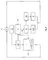
- the FIG. 3 shows the components of an operating device for implementing the two operating modes and comprises a control unit 11 of the vehicle 10, which is connected to the actuating surface 1.11 of the control element 1.10 of the vent 1.1, wherein by means of a sensor technology, the touch of this actuating surface is detected and evaluated 1.11 by the finger of an operator, in particular their operating time. Furthermore, the control unit 11 is connected to the rotary switch 2.2 and to the on-board monitor 3. The adjustment made by an operator of the outflow volume at the vent 1.1 in the first operating mode I or in the second operating mode II is implemented by the controller 11 by means of a drive 5, for example. An electric motor, which according to the setting in the operating mode I or II, the air flow by opening or closing the vent 1.1 controls.
- the actuating surface 1.11 according to FIG. 1 has a vertically extending virtual slider with a handle (corresponding to a slide of a mechanical slider), which is vertically displaceable between two end points by touching the actuating surface 1.11 by means of a finger 6 of an operator.
- the operation of this slider requires an actuation period which corresponds at least to the first time interval and therefore activates the first operating mode I.
- the outflow volume at the vent 1.1 can be set between a value zero at which the touch point is at the lower end of the slide control and a maximum value at which the touch point is at the upper end of the slide control.
- a virtual slider is suitable for intuitively setting the value of the outflow volume at the outlet 1.1, and therefore represents only a rough setting of the desired value.
- the operator can not inaccurate the set value non-numerically only on the basis of the position of the touch point between the two end points detect. A precise adjustment of the desired air flow to the vent 1.1 is therefore not possible. Even one next to the slider applied scale or in FIG. 3 Status indicator displayed in a wedge shape can not display the exact value.
- the second operating mode II is activated.
- a pop-up menu 3.1 is displayed by the control unit 11 on the display of the on-board monitor 3, which serves to set the outflow volume at the vent 1.1 exactly by displaying the numerical value of the current setting.
- FIG. 2 shows an example of such a pop-up menu 3.1. After that, in the upper area of the display 3, all four outlets installed in the instrument panel 12 are shown. Thus, not only arranged between an instrument cluster and provided for the driver vents 1.1 and 1.2 are shown, but also vents 1.3 and 1.4 for the passenger of the vehicle 10. If the vent 1.1 for activating the operating mode II was tapped only briefly, this is Outlet 1.1 shown in the pop-up menu 3.1 graphically compared to the other vents 1.2, 1.3 and 1.4 highlighted.
- This selected for adjusting the Ausströmvolumens vent 1.1 is shown in the lower part of the display 3 with a numeric display 4, which indicates the exact value, namely 26% of the Ausströmvolumens the vent 1.1 and an upwardly pointing up arrow P1 and one down pointing down arrow P2.
- These two arrows P1 and P2 can be used to set the value of the discharge volume exactly. There are two options for this.
- the area of this numerical display 4 represents a further operating element 2.1 with touch-sensitive actuating surface arranged in the area of the arrows P1 and P2. During the contact of the up arrow P1 or the down arrow P2 the value of the outflow volume is increased or decreased.
- the adjustment of the outflow volume at the outflow device 1.1 by means of the display 4 can also be effected by actuation of the rotary switch 2.2 as a further operating element.
- a graphical element on the display 3 is selected by optical highlighting and activated by pressing this rotary switch 2.2, the corresponding function.
- either the up arrow P1 or the down arrow P2 can be selected and activated by pressing, and then the desired numerical value can be set as the outflow volume of the outflow 1.1.
- the operating mode I it is of course also possible that subsequently according to the arrow P3 (see. FIG. 3 ) the operating mode II is activated by the operator.
- the pop-up menu 3.1 can also be realized in such a way that not only the outflow volume of the vent 1.1 selected by tapping the control panel 1.10 can be set via this pop-up menu 3.1, but also the outflow volume of the further vent 1.2 shown in the upper area of the display 3 , 1.3 and 1.4. If the display 3 is designed as a touch display and thus serves as a further control element 2.1, the other outlets 1.2, 1.3 and 1.4 by tapping each selected and then by tapping the arrows P1 and P2, the outflow volume can be adjusted.
- the adjustment of the outflow volume of one of the further outlets 1.2, 1.3 or 1.4 can also be carried out with the rotary switch 2.2 as another operating element by first selecting an outflow in the upper area of the display 3 and then one of the arrows P1 or P2 for setting the numerical Value of the outflow volume is activated.
- a function can be provided with which the outflow volume of all vents 1.1, 1.2, 1.3 and 1.4 can be set to a value simultaneously so that the same outflow volume of an air stream exits at all vents.
- a graphic element is provided on the display 3, which either has an actuating surface as a touchpad for activating the function or which can be selected and activated via the rotary switch 2.2.
Abstract
Description
- Die Erfindung betrifft ein Verfahren zum Bedienen einer Klimaanlage eines Fahrzeugs gemäß dem Oberbegriff des Patentanspruchs 1. Ferner betrifft die Erfindung eine Bedienvorrichtung zur Durchführung des erfindungsgemäßen Verfahrens.
- Eine gattungsbildende Bedienungsvorrichtung für eine Klimaanlage eines Fahrzeugs ist aus der
DE 10 2009 011 710 A1 bekannt. Die Luftausströmer diese Klimaanlage umfassen Anzeige- und Bedienelemente, mit welchem die Ausströmrichtung der Luft und das Ausströmvolumen einstellbar sind. Die Ausströmrichtung wird mittels eines mechanischen Bedienelementes eingestellt, während für die Einstellung des Ausströmvolumens ein kapazitiver Slider in der Art eines Schiebereglers verwendet wird, welcher durch Annäherung oder Berührung und horizontaler Bewegung durch Gleiten auf einer Bedienoberfläche bedienbar ist. - Nachteilig an solchen sensorischen Oberflächen ist jedoch, dass eine genaue Einstellung eines gewünschten Luftstromes nicht möglich ist, da keine Rückmeldung über den eingestellten Wert des Luftstromes ausgegeben wird. Mit einer solchen Sensorik kann daher nur eine grobe Einstellung des Ausströmvolumens vorgenommen werden.
- Aufgabe der Erfindung ist es ein Verfahren zum Bedienen einer Klimaanlage eines Fahrzeugs der eingangs genannten Art dahingehend zu verbessern, dass neben einer groben bzw. ungenauen Einstellung des Ausströmvolumens an einem Ausströmer auch eine genaue Einstellung ermöglicht wird. Ferner ist es Aufgabe der Erfindung eine Bedienvorrichtung zur Durchführung des ordnungsgemäßen Verfahrens anzugeben.
- Diese Aufgabe wird gelöst durch ein Verfahren mit den Merkmalen des Patentanspruchs 1.
- Ein solches Verfahren zum Bedienen einer Klimaanlage eines Fahrzeugs mit wenigstens einem ein Bedienelement aufweisenden Ausströmer, wobei das Ausströmvolumen mittels einer berührungsempfindlichen Betätigungsfläche des Bedienelementes eingestellt wird, zeichnet sich erfindungsgemäß dadurch aus, dass
- bei einer Betätigung des Bedienelementes für ein definiertes erstes Zeitintervall eine Schiebereglerfunktion zur Einstellung des Ausströmvolumens aktiviert wird,
- bei einer Betätigung des Bedienelementes für ein definiertes zweites Zeitintervall, welches kürzer als das erste Zeitintervall ist, auf einem Bordmonitor des Fahrzeugs ein Popup-Menü mit einer optischen Anzeige des numerischen Wertes des aktuellen Ausströmvolumens, zur Einstellung des Ausströmvolumens eingeblendet wird, und
- mittels eines weiteren Bedienelementes in dem Popup-Menü die Einstellung des Ausströmvolumens mit gleichzeitiger optischer Anzeige des numerischen Wertes des eingestellten Ausströmvolumens vorgenommen wird.
- Bei diesem erfindungsgemäßen Verfahren werden zwei Bedienmodi bereitgestellt, nämlich ein erster Bedienmodus, bei welchem die Betätigungsfläche des Bedienelementes für die Zeitdauer eines ersten Zeitintervalls betätigt wird, sowie ein zweiter Bedienmodus, der dann aktiviert wird, wenn die Betätigungsfläche des Bedienelementes für die Zeitdauer eines gegenüber dem ersten Zeitintervalls kürzeren Zeitintervalls betätigt wird. Dieses zweite Zeitintervall entspricht einem kurzen Antippen der Betätigungsfläche des Bedienelementes. Mit diesem kurzen Antippen der Betätigungsfläche des Bedienelementes wird auf dem Display eines Bordmonitor ein Popup-Menü eingeblendet, über welches dann mittels eines weiteren Bedienelementes eine präzise Einstellung des Ausströmvolumens vorgenommen werden kann. Gleichzeitig wird mit diesem Popup-Menü der numerische Wert des aktuell eingestellten Ausströmvolumens exakt angezeigt.
- Wird dagegen die Betätigungsfläche des Bedienelementes nicht nur kurz angetippt, sondern länger entsprechend der Zeitdauer des ersten Zeitintervalls betätigt, indem mit dem Finger eine bewegende Berührung mittels eines auf der Betätigungsfläche des Bedienelementes dargestellten Schiebereglers ausgeführt wird, wird der erste Bedienmodus aktiviert. Mit dem dargestellten virtuellen Schieberegler kann das Ausströmvolumen lediglich grob eingestellt werden, da der eingestellte Wert nur grafisch, also nichtnumerisch bspw. durch die Stellung des Schiebereglers angezeigt wird.
- In einer bevorzugten Ausführungsform der Erfindung wird der Bordmonitor mit einem berührungsempfindlichen Bildschirm als weiteres Bedienelement ausgebildet. Alternativ ist es weiterbildungsgemäß auch möglich, dass ein Drehschalter als weiteres Bedienelement bereitgestellt wird.
- Gemäß einer Weiterbildung des erfindungsgemäßen Verfahrens werden mit dem Popup-Menü weitere Ausströmer der Klimaanlage auf dem Bordmonitor eingeblendet, wobei das Ausströmvolumen der weiteren Ausströmer mittels des weiteren Bedienelementes einstellbar ist. Ferner kann das erfindungsgemäße Verfahren auch derart ausgeführt werden, dass das Ausströmvolumen für alle Ausströmer gleichzeitig mittels des weiteren Bedienelementes einstellbar ist.
- Die weitere Aufgabe wird gelöst durch eine Bedienvorrichtung mit den Merkmalen des Patentanspruchs 6.
- Eine solche Bedienvorrichtung für die Bedienung einer Klimaanlage eines Fahrzeugs mit wenigstens einem ein Bedienelement aufweisenden Ausströmer, wobei das Ausströmvolumen mittels einer berührungsempfindlichen Betätigungsfläche des Bedienelementes einstellbar ist, und mit einer Steuervorrichtung, die mit dem Bedienelement verbunden ist, zeichnet sich erfindungsgemäß dadurch aus, dass
- die Steuervorrichtung ausgebildet ist, bei einer Betätigung des Bedienelementes für ein definiertes erstes Zeitintervall eine Schiebereglerfunktion zur Einstellung des Ausströmvolumens zu realisieren,
- die Steuervorrichtung ausgebildet ist, bei einer Betätigung des Bedienelementes für ein definiertes gegenüber dem ersten Zeitintervall kürzeres zweites Zeitintervall auf einem Bordmonitor des Fahrzeugs ein Popup-Menü mit einer optischen Anzeige des numerischen Wertes des aktuellen Ausströmvolumens einzublenden, welches die Einstellung des Ausströmvolumens ermöglicht, und
- ein weiteres Bedienelement zur Einstellung des Ausströmvolumens in dem Popup-Menü vorgesehen ist.
- Diese erfindungsgemäße Bedienvorrichtung weist auch die oben beschriebenen Vorteile des erfindungsgemäßen Verfahrens auf.
- Bei dieser Bedienvorrichtung ist weiterbildungsgemäß vorgesehen, dass der Bordmonitor mit einem berührungsempfindlichen Bildschirm als weiteres Bedienelement ausgebildet ist und/oder ein Drehschalter das weitere Bedienelement vorgesehen ist.
- Die Erfindung wird nachfolgend anhand eines Ausführungsbeispiels unter Bezugnahme auf die beigefügten Figuren ausführlich beschrieben. Es zeigen:
- Figur 1
- eine schematische Darstellung eines in einer Instrumententafel eines Fahrzeugs angeordneten Luftausströmers mit einem Bedienelement,
- Figur 2
- eine schematische Darstellung einer Instrumententafel mit Luftausströmern gemäß
Figur 1 sowie einem Bordmonitor eines Fahrerinformationssystems, und - Figur 3
- ein Funktionsblockschaltbild zur Erläuterung des erfindungsgemäßen Verfahrens.
- Die
Figuren 1 und2 zeigen jeweils einen Ausschnitt einer Instrumententafel 12 eines Fahrzeugs 10 mit einer Klimaanlage mit zugehörigen Luftausströmern. So zeigtFigur 1 einen Ausströmer 1.1 mit einem zugehörigen Bedienelement 1.10 undFigur 2 zwei weitere Ausströmer 1.2 und 1.3 mit jeweils einem zugehörigen Bedienelement 1.20 und 1.30. Zwischen diesen beiden Ausströmern befindet sich an der Instrumententafel 12 ein Bordmonitor 3 mit einem Display als Anzeigefeld eines Fahrerinformationssystems des Fahrzeugs 10, welches zusammen mit einem Drehschalter 2.2 eine Multifunktionsbedienvorrichtung, die auch als Multi Media Interface (MMI) bezeichnet wird, bildet. Die Funktion eines solchen MMI-Systems ist im Wesentlichen die Bedienung von Radio, CD/TV, Telefon und Navigationssystem sowie der Einstellung der Klimaanlage. - Die in den
Figuren 1 und2 dargestellten Ausströmer 1.1, 1.2 und 1.3 der Instrumententafel 12 sind mit Luftleitlamellen ausgebildet, die mittels eines mechanischen Bedienelementes 1.12, 1.22 bzw. 1.32 zur Einstellung der Ausströmrichtung verstellt werden können. Die Einstellung der Ausströmvolumen an den Ausströmern 1.1, 1.2 und 1.3 erfolgt jedoch nicht mittels mechanischen Bedienelementen, sondern mit berührungsempfindlichen Betätigungsflächen sowie mittels des Bordmonitors 3, wie dies nachfolgend erläutert wird. - Hierzu weisen diese Ausströmer 1.1, 1.2 und 1.3 jeweils ein Bedienelement 1.10, 1.20 und 1.30 auf, die mit einer berührungsempfindlichen Betätigungsfläche bzw. berührungsempfindlichen Bedienoberfläche 1.11, 1.21 bzw. 1.31 in der Art eines Touchpads realisiert sind. Die Ausströmer 1.1, 1.2 und 1.3 sind mit einer 4-eckigen Kontur ausgeführt, so dass die Bedienelemente 1.10, 1.20 und 1.30 mit einer rechteckigen Kontur zu einer Seite der Ausströmer 1.1, 1.2 und 1.3 direkt benachbart angeordnet sind.
- Zur Einstellung des Ausströmvolumens an einem Ausströmer 1.1, 1.2 und 1.3 stehen zwei Bedienmodi zur Verfügung. Diese beiden Bedienmodi werden in Abhängigkeit der Betätigungsdauer des Bedienelementes 1.10, 1.20 bzw. 1.30 aktiviert, hängen also davon ab, wie lange der Finger 6 einer Bedienperson die berührungsempfindliche Betätigungsfläche 1.11, 1.21 bzw. 1.31 berührt.
- So wird ein erster Bedienmodus bereitgestellt, indem die Betätigungsfläche 1.11, 1.21 bzw. 1.31 des Bedienelementes 1.10, 1.20 bzw. 1.30 für die Zeitdauer eines ersten Zeitintervalls betätigt wird. Wird dagegen die Betätigungsfläche 1.11, 1.21 bzw. 1.31 des Bedienelementes 1.10, 1.20 bzw. 1.30 für eine gegenüber dem ersten Zeitintervall kürzeren zweiten Zeitintervall betätigt, wird ein zweiter Bedienmodus aktiviert. Das zweite Zeitintervall entspricht einem kurzen Antippen mit einem Finger 6 einer Bedienperson, entspricht also einer Zeitdauer von bspw. 1 bis 2 s, während das erste Zeitintervall einem langen Antippen von mehr als 2 s, bspw. von 5 s entspricht.
- Diese beiden Bedienmodi werden nachfolgend anhand der
Figuren 1 und2 zusammen mit dem Funktionsblockschaltbild gemäßFigur 3 am Beispiel des Ausströmers 1.1 erläutert. - Die
Figur 3 zeigt die Komponenten einer Bedienvorrichtung zur Realisierung der beiden Betriebsmodi und umfasst ein Steuergerät 11 des Fahrzeugs 10, welches mit der Betätigungsfläche 1.11 des Bedienelementes 1.10 des Ausströmers 1.1 verbunden ist, wobei mittels einer Sensortechnik die Berührung dieser Betätigungsfläche 1.11 durch den Finger einer Bedienperson, insbesondere deren Betätigungsdauer detektiert und ausgewertet wird. Ferner ist das Steuergerät 11 mit dem Drehschalter 2.2 sowie mit dem Bordmonitor 3 verbunden. Die von einer Bedienperson vorgenommene Einstellung des Ausströmvolumens an dem Ausströmer 1.1 im ersten Bedienmodus I oder im zweiten Bedienmodus II wird von dem Steuergerät 11 mittels eines Antriebs 5, bspw. eines Elektromotors umgesetzt, welches entsprechend der Einstellung im Bedienmodus I oder II den Luftstrom durch Öffnen oder Schließen des Ausströmers 1.1 steuert. - Die Betätigungsfläche 1.11 gemäß
Figur 1 weist einen vertikal verlaufenden virtuellen Schieberegler mit einem Anfasspunkt (entsprechend einem Schieber eines mechanischen Schiebereglers) auf, der zwischen zwei Endpunkten durch Berühren der Betätigungsfläche 1.11 mittels eines Fingers 6 einer Bedienperson vertikal verschiebbar ist. Die Betätigung dieses Schiebereglers erfordert eine Betätigungsdauer, die zumindest dem ersten Zeitintervall entspricht und daher den ersten Bedienmodus I aktiviert. - Damit lässt sich in diesem Bedienmodus I das Ausströmvolumen am Ausströmer 1.1 zwischen einem Wert Null, bei welchem sich der Anfasspunkt am unteren Ende des Schiebereglers befindet, und einem maximalen Wert, bei welchem sich der Anfasspunkt am oberen Ende des Schiebereglers befindet, einstellen. Ein solcher virtueller Schieberegler eignet sich in der Regel zur intuitiven Einstellung des Wertes des Ausströmvolumens am Ausströmer 1.1, und stellt daher nur eine grobe Einstellung des gewünschten Wertes dar. Die Bedienperson kann den eingestellten Wert nichtnumerisch nur anhand der Stellung des Anfasspunktes zwischen den beiden Endpunkten ungenau erkennen. Eine genaue Einstellung des gewünschten Luftstromes an dem Ausströmer 1.1 ist damit nicht möglich. Selbst eine neben dem Schieberegler aufgetragene Skala oder ein in
Figur 3 in einer Keilform dargestellter Statusanzeiger kann den exakten Wert nicht anzeigen. - Falls nach dem aktivierten Bedienmodus I keine weitere Betätigung erfolgt, wird entsprechend dem Funktionsblockschaltbild nach
Figur 3 entsprechend der Stellung des Schiebereglers der Antrieb 5 angesteuert. - Entspricht dagegen die Betätigungsdauer der Betätigungsfläche 1.11 des Bedienelementes 1.10 dem zweiten Zeitintervall entsprechend einem kurzen Antippen durch den Finger 6 einer Bedienperson, wird der zweite Bedienmodus II aktiviert. Hierdurch wird von dem Steuergerät 11 auf dem Display des Bordmonitors 3 ein Popup-Menü 3.1 eingeblendet, welches dazu dient das Ausströmvolumen an dem Ausströmer 1.1 durch Anzeige des numerischen Wertes der aktuellen Einstellung exakt einzustellen.
- Die
Figur 2 zeigt beispielhaft ein solches Popup-Menü 3.1. Hiernach sind im oberen Bereich des Displays 3 alle vier in der Instrumententafel 12 eingebaute Ausströmer dargestellt. So sind nicht nur die zwischen einem Kombiinstrument angeordneten und für den Fahrer vorgesehenen Ausströmer 1.1 und 1.2 dargestellt, sondern auch Ausströmer 1.3 und 1.4 für den Beifahrer des Fahrzeugs 10. Wenn der Ausströmer 1.1 zur Aktivierung des Bedienmodus II nur kurz an getippt wurde, wird dieser Ausströmer 1.1 in dem Popup-Menü 3.1 grafisch gegenüber den anderen Ausströmern 1.2, 1.3 und 1.4 hervorgehoben dargestellt. Dieser für die Einstellung des Ausströmvolumens ausgewählte Ausströmer 1.1 ist im unteren Bereich des Displays 3 mit einer numerischen Anzeige 4 dargestellt, die den genauen Wert, nämlich 26 % des Ausströmvolumens am Ausströmer 1.1 anzeigt sowie einen nach oben zeigenden Up-Pfeil P1 und einen nach unten zeigenden Down-Pfeil P2. Über diese beiden Pfeile P1 und P2 kann der Wert des Ausströmvolumens exakt eingestellt werden. Hierzu stehen zwei Möglichkeiten zur Verfügung. - Ist das Display 3 als Touch-Display ausgeführt, so stellt der Bereich dieser numerischen Anzeige 4 ein weiteres Bedienelement 2.1 mit im Bereich der Pfeile P1 und P2 angeordneten berührungsempfindlichen Betätigungsfläche dar. Während der Berührung des Up-Pfeils P1 bzw. des Down-Pfeils P2 wird der Wert des Ausströmvolumens erhöht bzw. erniedrigt.
- Die Einstellung des Ausströmvolumens am Ausströmer 1.1 mittels der Anzeige 4 kann auch durch eine Betätigung des Drehschalters 2.2 als weiteres Bedienelement erfolgen. Mittels dieses Drehschalters 2.2 wird ein grafisches Element auf dem Display 3 durch optisches Hervorheben ausgewählt und durch Drücken dieses Drehschalters 2.2 die entsprechende Funktion aktiviert. So kann mittels dieses Drehschalters 2.2 entweder der Up-Pfeil P1 oder der Down-Pfeil P2 ausgewählt und durch Drücken aktiviert und anschließendes Drehen der gewünschte Zahlenwert als Ausströmvolumen des Ausströmers 1.1 eingestellt werden.
- Wenn gemäß
Figur 3 entweder mittels des Touch-Displays 3 als weiteres Bedienelement 2.1 oder mittels des Drehschalters als weiteres Bedienelement 2.2 die Einstellung vorgenommen wurde, wird entsprechend dem eingestellten Wert der Antrieb 5 von dem Steuergerät 11 angesteuert. - Wenn eine Bedienperson zunächst den Bedienmodus I aktiviert hat, ist es natürlich auch möglich, dass anschließend entsprechend des Pfeils P3 (vgl.
Figur 3 ) der Bedienmodus II durch die Bedienperson aktiviert wird. - Das Popup-Menü 3.1 kann auch so realisiert werden, dass nicht nur das Ausströmvolumen des durch Antippen des Bedienteil 1.10 ausgewählten Ausströmers 1.1 über dieses Popup-Menü 3.1 angestellt werden kann, sondern auch das Ausströmvolumen der im oberen Bereich des Displays 3 dargestellten weiteren Ausströmer 1.2, 1.3 und 1.4. Falls das Display 3 als Touch-Display ausgeführt ist und somit als weiteres Bedienelement 2.1 dient, können die weiteren Ausströmer 1.2, 1.3 und 1.4 durch Antippen jeweils ausgewählt und anschließend durch Antippen der Pfeile P1 und P2 das Ausströmvolumen eingestellt werden. Darüber hinaus kann die Einstellung des Ausströmvolumens eines der weiteren Ausströmer 1.2, 1.3 oder 1.4 auch mit dem Drehschalter 2.2 als weiteres Bedienelement durchgeführt werden, indem zunächst ein Ausströmer im oberen Bereich des Displays 3 ausgewählt und anschließend einer der Pfeile P1 oder P2 zur Einstellung des numerischen Wertes des Ausströmvolumens aktiviert wird.
- Schließlich kann in dem Popup-Menü 3.1 zusätzlich eine Funktion bereitgestellt werden, mit welcher das Ausströmvolumen von allen Ausströmern 1.1, 1.2, 1.3 und 1.4 gleichzeitig auf einen Wert eingestellt werden kann, so dass an allen Ausströmern das gleiche Ausströmvolumen eines Luftstromes austritt. Für eine solche Funktion wird auf dem Display 3 ein grafisches Element bereitgestellt, welches entweder eine Betätigungsfläche als Touchpad zur Aktivierung der Funktion aufweist oder welches über den Drehschalter 2.2 ausgewählt und aktiviert werden kann.
-
- 1.1
- Ausströmer einer Klimaanlage des Fahrzeugs 10
- 1.10
- Bedienelement des Ausströmers 1.1
- 1.11
- Betätigungsfläche des Bedienelementes 1.10
- 1.12
- mechanisches Bedienelement
- 1.2
- Ausströmer einer Klimaanlage des Fahrzeugs 10
- 1.20
- Bedienelement des Ausströmers 1.2
- 1.21
- Betätigungsfläche des Bedienelementes 1.20
- 1.22
- mechanisches Bedienelement
- 1.3
- Ausströmer einer Klimaanlage des Fahrzeugs 10
- 1.30
- Bedienelement des Ausströmers 1.3
- 1.31
- Betätigungsfläche des Bedienelementes 1.30
- 1.32
- mechanisches Bedienelement
- 2.1
- weiteres Bedienelement
- 2.2
- weiteres Bedienelement, Drehschalter
- 3
- Bordmonitor, Display
- 3.1
- Popup-Menü
- 4
- numerische Anzeige
- 5
- Antrieb, Elektromotor
- 6
- Finger einer Bedienperson
- 10
- Fahrzeug
- 11
- Steuervorrichtung, Steuergerät
- 12
- Instrumententafel des Fahrzeugs 10
Claims (8)
- Verfahren zum Bedienen einer Klimaanlage eines Fahrzeugs (10) mit wenigstens einem ein Bedienelement (1.10) aufweisenden Ausströmer (1.1), wobei das Ausströmvolumen mittels einer berührungsempfindlichen Betätigungsfläche (1.11) des Bedienelementes (1.10) eingestellt wird,
dadurch gekennzeichnet, dass- bei einer Betätigung des Bedienelementes (1.10) für ein definiertes erstes Zeitintervall eine Schiebereglerfunktion zur Einstellung des Ausströmvolumens aktiviert wird,- bei einer Betätigung des Bedienelementes (1.10) für ein definiertes zweites Zeitintervall, welches kürzer als das erste Zeitintervall ist, auf einem Bordmonitor (3) des Fahrzeugs (10) ein Popup-Menü (3.1) mit einer optischen Anzeige des numerischen Wertes des aktuellen Ausströmvolumens zur Einstellung des Ausströmvolumens eingeblendet wird, und- mittels eines weiteren Bedienelementes (2.1, 2.2) in dem Popup-Menü (3.1) die Einstellung des Ausströmvolumens mit gleichzeitiger optischer Anzeige (4) des numerischen Wertes des eingestellten Ausströmvolumens vorgenommen wird. - Verfahren nach Anspruch 1,
dadurch gekennzeichnet, dass
der Bordmonitor (3) mit einem berührungsempfindlichen Bildschirm als weiteres Bedienelement (2.1) ausgebildet wird. - Verfahren nach Anspruch 1 oder 2,
dadurch gekennzeichnet, dass
als weiteres Bedienelement ein Drehschalter (2.2) bereitgestellt wird. - Verfahren nach einem der vorhergehenden Ansprüche,
dadurch gekennzeichnet, dass
mit dem Popup-Menü (3.1) weitere Ausströmer (1.2, 1.3, 1.4) der Klimaanlage auf dem Bordmonitor (3) eingeblendet werden, wobei das Ausströmvolumen der weiteren Ausströmer (1.2, 1.3, 1.4) mittels des weiteren Bedienelementes (2.1, 2.2) einstellbar sind. - Verfahren nach einem der vorhergehenden Ansprüche,
dadurch gekennzeichnet, dass
mit dem Popup-Menü (3.1) weitere Ausströmer (1.2, 1.3, 1.4) der Klimaanlage auf dem Bordmonitor (3) eingeblendet werden, wobei das Ausströmvolumen für alle Ausströmer (1.1, 1.2, 1.3, 1.4) gleichzeitig mittels des weiteren Bedienelementes (2.1, 2.2) einstellbar ist. - Bedienvorrichtung für die Bedienung einer Klimaanlage eines Fahrzeugs (10) mit wenigstens einem ein Bedienelement (1.10) aufweisenden Ausströmer (1.1), wobei das Ausströmvolumen mittels einer berührungsempfindlichen Betätigungsfläche (1.11) des Bedienelementes (1.10) einstellbar ist und mit einer Steuervorrichtung (11), die mit dem Bedienelement (1.10) verbunden ist,
dadurch gekennzeichnet, dass- die Steuervorrichtung (11) ausgebildet ist, bei einer Betätigung des Bedienelementes (1.10) für ein definiertes erstes Zeitintervall eine Schiebereglerfunktion zur Einstellung des Ausströmvolumens zu realisieren,- die Steuervorrichtung (11) ausgebildet ist, bei einer Betätigung des Bedienelementes (1.10) für ein definiertes gegenüber dem ersten Zeitintervall kürzeres zweites Zeitintervall auf einem Bordmonitor (3) des Fahrzeugs (10) ein Popup-Menü (3.1) mit einer optischen Anzeige (4) des numerischen Wertes des aktuellen Ausströmvolumens einzublenden, welches die Einstellung des Ausströmvolumens ermöglicht, und- ein weiteres Bedienelement (2.1, 2.2) zur Einstellung des Ausströmvolumens in dem Popup-Menü (3.1) vorgesehen ist. - Bedienvorrichtung nach Anspruch 6,
dadurch gekennzeichnet, dass
der Bordmonitor (3) mit einem berührungsempfindlichen Bildschirm als weiteres Bedienelement (2.1) ausgebildet ist. - Bedienvorrichtung nach Anspruch 6 oder 7,
dadurch gekennzeichnet, dass
das weitere Bedienelement ein Drehschalter (2.2) ist.
Applications Claiming Priority (1)
| Application Number | Priority Date | Filing Date | Title |
|---|---|---|---|
| DE102015005126.1A DE102015005126B3 (de) | 2015-04-22 | 2015-04-22 | Verfahren und Bedienungsvorrichtung zum Bedienen einer Klimaanlage eines Fahrzeugs |
Publications (3)
| Publication Number | Publication Date |
|---|---|
| EP3085559A2 true EP3085559A2 (de) | 2016-10-26 |
| EP3085559A3 EP3085559A3 (de) | 2017-01-18 |
| EP3085559B1 EP3085559B1 (de) | 2018-01-10 |
Family
ID=54539803
Family Applications (1)
| Application Number | Title | Priority Date | Filing Date |
|---|---|---|---|
| EP15003215.9A Active EP3085559B1 (de) | 2015-04-22 | 2015-11-10 | Verfahren und bedienungsvorrichtung zum bedienen einer klimaanlage eines fahrzeugs |
Country Status (4)
| Country | Link |
|---|---|
| US (1) | US9889721B2 (de) |
| EP (1) | EP3085559B1 (de) |
| CN (1) | CN106064554B (de) |
| DE (1) | DE102015005126B3 (de) |
Cited By (1)
| Publication number | Priority date | Publication date | Assignee | Title |
|---|---|---|---|---|
| WO2019120891A1 (fr) * | 2017-12-21 | 2019-06-27 | Psa Automobiles Sa | Dispositif d'aeration compact a effet coanda pour vehicule automobile integrant un module de controle pourvu d'une façade de commande |
Families Citing this family (9)
| Publication number | Priority date | Publication date | Assignee | Title |
|---|---|---|---|---|
| KR101640053B1 (ko) * | 2015-01-02 | 2016-07-18 | 현대자동차주식회사 | 차량용 디스플레이 장치 및 이를 포함하는 차량 |
| DE102016210597A1 (de) * | 2016-06-15 | 2017-12-21 | Bayerische Motoren Werke Aktiengesellschaft | Luftausströmer für ein Fortbewegungsmittel |
| DE102016210624A1 (de) * | 2016-06-15 | 2017-12-21 | Bayerische Motoren Werke Aktiengesellschaft | Fortbewegungsmittel und Anordnung zur Ansteuerung einer Heiz-/Klimaanlage für ein Fortbewegungsmittel |
| EP3269570B1 (de) * | 2016-07-14 | 2019-09-11 | Vestel Elektronik Sanayi ve Ticaret A.S. | Anzeigeeinheit mit integrierter einrichtung zur luftstromablenkung |
| DE102016215395A1 (de) * | 2016-08-17 | 2018-02-22 | Ford Global Technologies, Llc | Verfahren zum Steuern eines Heizungs-, Lüftungs- und Klimaanlagen-Systems eines Fahrzeugs |
| DE102016216543A1 (de) | 2016-09-01 | 2018-03-01 | Audi Ag | Bedieneinrichtung für ein Komfortsystem eines Kraftfahrzeugs, Komfortsystem mit einer Bedieneinrichtung und Kraftfahrzeug mit einem Komfortsystem |
| DE102017215809B4 (de) | 2017-09-07 | 2022-06-30 | Bayerische Motoren Werke Aktiengesellschaft | Luftauslassvorrichtung für einen Innenraum eines Kraftfahrzeugs und System |
| DE102018122393A1 (de) * | 2017-09-15 | 2019-03-21 | Hanon Systems | Klimaanlagen-Gebläseeinheit für Fahrzeug |
| DE102018100939A1 (de) * | 2018-01-17 | 2019-07-18 | Dr. Ing. H.C. F. Porsche Aktiengesellschaft | Verfahren zum Betrieb eines Lufteinströmers |
Citations (1)
| Publication number | Priority date | Publication date | Assignee | Title |
|---|---|---|---|---|
| DE102009011710A1 (de) | 2009-03-09 | 2010-09-16 | Volkswagen Ag | Anordnung zur Luftverteilung im Innenraum eines Kraftfahrzeuges |
Family Cites Families (10)
| Publication number | Priority date | Publication date | Assignee | Title |
|---|---|---|---|---|
| DE102008018562A1 (de) * | 2008-04-12 | 2009-10-15 | Daimler Ag | Klimatisierungssystem und Verfahren zum Betreiben einer Klimaanlage eines Klimatisierungssystems |
| DE102008052442A1 (de) * | 2008-10-21 | 2009-06-10 | Daimler Ag | Verfahren und Bedienvorrichtung zur Bedienung mehrerer Funktionseinheiten in einem Kraftfahrzeug |
| DE102010028051A1 (de) * | 2009-05-04 | 2011-01-05 | Behr Gmbh & Co. Kg | Klimaanlage für ein Kraftfahrzeug, sowie Verfahren und Regeleinheit einer solchen Klimaanlage |
| DE102010010441A1 (de) * | 2010-02-25 | 2011-08-25 | Dr. Ing. h.c. F. Porsche Aktiengesellschaft, 70435 | Belüftungs- und Klimasystem eines Kraftfahrzeugs |
| DE102010018105B4 (de) * | 2010-04-24 | 2021-06-24 | Volkswagen Ag | Fahrzeugcockpit mit einer Bedieneinrichtung zum Erfassen von Nutzereingaben und Verfahren zum Betreiben einer solchen |
| DE102012021519B4 (de) * | 2012-11-02 | 2023-05-04 | Volkswagen Aktiengesellschaft | Lüftungssystem für ein Kraftfahrzeug sowie Verfahren zum Betreiben eines solchen |
| DE102013220994A1 (de) * | 2013-10-16 | 2015-04-16 | Volkswagen Aktiengesellschaft | Verfahren und Vorrichtung zur Einstellung von Komfortparametern sowie Kraftfahrzeug |
| DE102013021477A1 (de) * | 2013-12-17 | 2014-08-14 | Daimler Ag | Bedienvorrichtung für ein Kraftfahrzeug |
| JP5860915B2 (ja) * | 2014-03-28 | 2016-02-16 | 富士重工業株式会社 | 空調機能および表示機能を備える車両 |
| CN104442281B (zh) * | 2014-12-08 | 2016-11-30 | 重庆瑞阳科技开发有限公司 | 一种汽车及其空调控制器模块 |
-
2015
- 2015-04-22 DE DE102015005126.1A patent/DE102015005126B3/de not_active Expired - Fee Related
- 2015-11-10 EP EP15003215.9A patent/EP3085559B1/de active Active
-
2016
- 2016-01-14 CN CN201610024470.0A patent/CN106064554B/zh active Active
- 2016-04-21 US US15/135,017 patent/US9889721B2/en active Active
Patent Citations (1)
| Publication number | Priority date | Publication date | Assignee | Title |
|---|---|---|---|---|
| DE102009011710A1 (de) | 2009-03-09 | 2010-09-16 | Volkswagen Ag | Anordnung zur Luftverteilung im Innenraum eines Kraftfahrzeuges |
Cited By (3)
| Publication number | Priority date | Publication date | Assignee | Title |
|---|---|---|---|---|
| WO2019120891A1 (fr) * | 2017-12-21 | 2019-06-27 | Psa Automobiles Sa | Dispositif d'aeration compact a effet coanda pour vehicule automobile integrant un module de controle pourvu d'une façade de commande |
| FR3075696A1 (fr) * | 2017-12-21 | 2019-06-28 | Psa Automobiles Sa | Dispositif d’aeration compact a effet coanda pour vehicule automobile integrant un module de controle pourvu d’une facade de commande. |
| US11465464B2 (en) | 2017-12-21 | 2022-10-11 | Faurecia Interieur Industrie | Compact coanda effect ventilation device for motor vehicle incorporating a control module provided with a control panel |
Also Published As
| Publication number | Publication date |
|---|---|
| EP3085559B1 (de) | 2018-01-10 |
| CN106064554A (zh) | 2016-11-02 |
| US20160311293A1 (en) | 2016-10-27 |
| CN106064554B (zh) | 2018-08-31 |
| US9889721B2 (en) | 2018-02-13 |
| DE102015005126B3 (de) | 2016-06-02 |
| EP3085559A3 (de) | 2017-01-18 |
Similar Documents
| Publication | Publication Date | Title |
|---|---|---|
| EP3085559B1 (de) | Verfahren und bedienungsvorrichtung zum bedienen einer klimaanlage eines fahrzeugs | |
| EP2885142B1 (de) | Bedienvorrichtung zum einstellen einer klimatisierungsvorrichtung eines fahrzeugs und verfahren hierzu | |
| EP2930049B1 (de) | Anwenderschnittstelle und Verfahren zur Anpassung einer Ansicht auf einer Anzeigeeinheit | |
| EP2822812B1 (de) | Kraftfahrzeug mit einem elektronischen rückspiegel | |
| EP1517224A2 (de) | Berührungsempfindliche Anzeigevorrichtung | |
| EP1953028B1 (de) | Anzeige- und Bedienvorrichtung eines Kraftfahrzeuges mit einer Erfassung von nutzerabhängigen Parametern | |
| EP3279018B1 (de) | Verfahren und bedienvorrichtung zum bedienen einer klimatisierungsvorrichtung eines fahrzeugs | |
| EP3574396A1 (de) | Verfahren zum betreiben einer mensch-maschinen-schnittstelle sowie mensch-maschinen-schnittstelle | |
| DE102014012550A1 (de) | Kraftfahrzeug-Bedienungsvorrichtung | |
| EP2883738A2 (de) | Verfahren und Anordnung zum Steuern von Funktionen eines Kraftfahrzeugs | |
| DE102012011179A1 (de) | Vorrichtung zur Bedienung einesKraftfahrzeuges | |
| WO2014170277A1 (de) | Kraftfahrzeug mit einer anzeige- und bedienvorrichtung und entsprechendes verfahren | |
| DE102008029159A1 (de) | Verfahren und Einstellsystem zum Einstellen eines Frontscheinwerferlichtkegels für ein Fahrzeug | |
| DE102015011648B4 (de) | Kraftfahrzeug-Bedienvorrichtung mit Schiebereglern und Verfahren zum Betreiben einer Bedienvorrichtung | |
| DE102009039114B4 (de) | Bedienvorrichtung für ein Fahrzeug | |
| EP3908475A1 (de) | Bedienvorrichtung zur bedienung mindestens eines gerätes und verfahren zur bedienung einer solchen bedienvorrichtung | |
| EP3263399B1 (de) | Verfahren und vorrichtung zum steuern der klimatisierung eines fahrzeugsitzes | |
| EP3188922B1 (de) | Bedienvorrichtung und verfahren zum bedienen von funktionen eines fahrzeugs, insbesondere eines kraftwagens | |
| WO2016005502A1 (de) | Mehrfunktionales bediensystem für ein kraftfahrzeug | |
| EP3924209A1 (de) | Bedienvorrichtung mit einem berührungsempfindlichen element und verfahren zum erfassen einer bediengeste | |
| DE102014016020A1 (de) | Steuerungsanordnung mit Lenkradbedienung | |
| DE102015225248B4 (de) | System zum Erfassen eines Wertes für einen von zumindest zwei Einstellungsparametern eines Kraftfahrzeugs | |
| DE102014014341B4 (de) | Verfahren zum Betreiben eines Infotainmentsystems eines Kraftfahrzeugs und Infotainmentsystem für ein Kraftfahrzeug | |
| DE102014014336A1 (de) | Bedienvorrichtung für ein Kraftfahrzeug | |
| EP3443422A1 (de) | Werkzeugmaschine sowie verwendung eines berührempfindlichen displays zur ansteuerung eines maschinenteils einer werkzeugmaschine |
Legal Events
| Date | Code | Title | Description |
|---|---|---|---|
| PUAI | Public reference made under article 153(3) epc to a published international application that has entered the european phase |
Free format text: ORIGINAL CODE: 0009012 |
|
| AK | Designated contracting states |
Kind code of ref document: A2 Designated state(s): AL AT BE BG CH CY CZ DE DK EE ES FI FR GB GR HR HU IE IS IT LI LT LU LV MC MK MT NL NO PL PT RO RS SE SI SK SM TR |
|
| AX | Request for extension of the european patent |
Extension state: BA ME |
|
| PUAL | Search report despatched |
Free format text: ORIGINAL CODE: 0009013 |
|
| AK | Designated contracting states |
Kind code of ref document: A3 Designated state(s): AL AT BE BG CH CY CZ DE DK EE ES FI FR GB GR HR HU IE IS IT LI LT LU LV MC MK MT NL NO PL PT RO RS SE SI SK SM TR |
|
| AX | Request for extension of the european patent |
Extension state: BA ME |
|
| RIC1 | Information provided on ipc code assigned before grant |
Ipc: B60K 37/06 20060101ALI20161213BHEP Ipc: B60H 1/34 20060101AFI20161213BHEP Ipc: B60H 1/00 20060101ALI20161213BHEP Ipc: B60K 35/00 20060101ALI20161213BHEP |
|
| STAA | Information on the status of an ep patent application or granted ep patent |
Free format text: STATUS: REQUEST FOR EXAMINATION WAS MADE |
|
| 17P | Request for examination filed |
Effective date: 20170718 |
|
| RBV | Designated contracting states (corrected) |
Designated state(s): AL AT BE BG CH CY CZ DE DK EE ES FI FR GB GR HR HU IE IS IT LI LT LU LV MC MK MT NL NO PL PT RO RS SE SI SK SM TR |
|
| GRAP | Despatch of communication of intention to grant a patent |
Free format text: ORIGINAL CODE: EPIDOSNIGR1 |
|
| STAA | Information on the status of an ep patent application or granted ep patent |
Free format text: STATUS: GRANT OF PATENT IS INTENDED |
|
| INTG | Intention to grant announced |
Effective date: 20170906 |
|
| GRAS | Grant fee paid |
Free format text: ORIGINAL CODE: EPIDOSNIGR3 |
|
| GRAA | (expected) grant |
Free format text: ORIGINAL CODE: 0009210 |
|
| STAA | Information on the status of an ep patent application or granted ep patent |
Free format text: STATUS: THE PATENT HAS BEEN GRANTED |
|
| AK | Designated contracting states |
Kind code of ref document: B1 Designated state(s): AL AT BE BG CH CY CZ DE DK EE ES FI FR GB GR HR HU IE IS IT LI LT LU LV MC MK MT NL NO PL PT RO RS SE SI SK SM TR |
|
| REG | Reference to a national code |
Ref country code: CH Ref legal event code: EP Ref country code: AT Ref legal event code: REF Ref document number: 961983 Country of ref document: AT Kind code of ref document: T Effective date: 20180115 |
|
| REG | Reference to a national code |
Ref country code: IE Ref legal event code: FG4D Free format text: LANGUAGE OF EP DOCUMENT: GERMAN |
|
| REG | Reference to a national code |
Ref country code: DE Ref legal event code: R096 Ref document number: 502015002788 Country of ref document: DE |
|
| REG | Reference to a national code |
Ref country code: NL Ref legal event code: MP Effective date: 20180110 |
|
| PG25 | Lapsed in a contracting state [announced via postgrant information from national office to epo] |
Ref country code: NL Free format text: LAPSE BECAUSE OF FAILURE TO SUBMIT A TRANSLATION OF THE DESCRIPTION OR TO PAY THE FEE WITHIN THE PRESCRIBED TIME-LIMIT Effective date: 20180110 |
|
| PG25 | Lapsed in a contracting state [announced via postgrant information from national office to epo] |
Ref country code: ES Free format text: LAPSE BECAUSE OF FAILURE TO SUBMIT A TRANSLATION OF THE DESCRIPTION OR TO PAY THE FEE WITHIN THE PRESCRIBED TIME-LIMIT Effective date: 20180110 Ref country code: HR Free format text: LAPSE BECAUSE OF FAILURE TO SUBMIT A TRANSLATION OF THE DESCRIPTION OR TO PAY THE FEE WITHIN THE PRESCRIBED TIME-LIMIT Effective date: 20180110 Ref country code: NO Free format text: LAPSE BECAUSE OF FAILURE TO SUBMIT A TRANSLATION OF THE DESCRIPTION OR TO PAY THE FEE WITHIN THE PRESCRIBED TIME-LIMIT Effective date: 20180410 Ref country code: FI Free format text: LAPSE BECAUSE OF FAILURE TO SUBMIT A TRANSLATION OF THE DESCRIPTION OR TO PAY THE FEE WITHIN THE PRESCRIBED TIME-LIMIT Effective date: 20180110 Ref country code: LT Free format text: LAPSE BECAUSE OF FAILURE TO SUBMIT A TRANSLATION OF THE DESCRIPTION OR TO PAY THE FEE WITHIN THE PRESCRIBED TIME-LIMIT Effective date: 20180110 Ref country code: CY Free format text: LAPSE BECAUSE OF FAILURE TO SUBMIT A TRANSLATION OF THE DESCRIPTION OR TO PAY THE FEE WITHIN THE PRESCRIBED TIME-LIMIT Effective date: 20180110 |
|
| PG25 | Lapsed in a contracting state [announced via postgrant information from national office to epo] |
Ref country code: IS Free format text: LAPSE BECAUSE OF FAILURE TO SUBMIT A TRANSLATION OF THE DESCRIPTION OR TO PAY THE FEE WITHIN THE PRESCRIBED TIME-LIMIT Effective date: 20180510 Ref country code: LV Free format text: LAPSE BECAUSE OF FAILURE TO SUBMIT A TRANSLATION OF THE DESCRIPTION OR TO PAY THE FEE WITHIN THE PRESCRIBED TIME-LIMIT Effective date: 20180110 Ref country code: SE Free format text: LAPSE BECAUSE OF FAILURE TO SUBMIT A TRANSLATION OF THE DESCRIPTION OR TO PAY THE FEE WITHIN THE PRESCRIBED TIME-LIMIT Effective date: 20180110 Ref country code: GR Free format text: LAPSE BECAUSE OF FAILURE TO SUBMIT A TRANSLATION OF THE DESCRIPTION OR TO PAY THE FEE WITHIN THE PRESCRIBED TIME-LIMIT Effective date: 20180411 Ref country code: PL Free format text: LAPSE BECAUSE OF FAILURE TO SUBMIT A TRANSLATION OF THE DESCRIPTION OR TO PAY THE FEE WITHIN THE PRESCRIBED TIME-LIMIT Effective date: 20180110 Ref country code: RS Free format text: LAPSE BECAUSE OF FAILURE TO SUBMIT A TRANSLATION OF THE DESCRIPTION OR TO PAY THE FEE WITHIN THE PRESCRIBED TIME-LIMIT Effective date: 20180110 Ref country code: BG Free format text: LAPSE BECAUSE OF FAILURE TO SUBMIT A TRANSLATION OF THE DESCRIPTION OR TO PAY THE FEE WITHIN THE PRESCRIBED TIME-LIMIT Effective date: 20180410 |
|
| PG25 | Lapsed in a contracting state [announced via postgrant information from national office to epo] |
Ref country code: MT Free format text: LAPSE BECAUSE OF FAILURE TO SUBMIT A TRANSLATION OF THE DESCRIPTION OR TO PAY THE FEE WITHIN THE PRESCRIBED TIME-LIMIT Effective date: 20180110 |
|
| REG | Reference to a national code |
Ref country code: DE Ref legal event code: R097 Ref document number: 502015002788 Country of ref document: DE |
|
| PG25 | Lapsed in a contracting state [announced via postgrant information from national office to epo] |
Ref country code: RO Free format text: LAPSE BECAUSE OF FAILURE TO SUBMIT A TRANSLATION OF THE DESCRIPTION OR TO PAY THE FEE WITHIN THE PRESCRIBED TIME-LIMIT Effective date: 20180110 Ref country code: IT Free format text: LAPSE BECAUSE OF FAILURE TO SUBMIT A TRANSLATION OF THE DESCRIPTION OR TO PAY THE FEE WITHIN THE PRESCRIBED TIME-LIMIT Effective date: 20180110 Ref country code: AL Free format text: LAPSE BECAUSE OF FAILURE TO SUBMIT A TRANSLATION OF THE DESCRIPTION OR TO PAY THE FEE WITHIN THE PRESCRIBED TIME-LIMIT Effective date: 20180110 Ref country code: EE Free format text: LAPSE BECAUSE OF FAILURE TO SUBMIT A TRANSLATION OF THE DESCRIPTION OR TO PAY THE FEE WITHIN THE PRESCRIBED TIME-LIMIT Effective date: 20180110 |
|
| PLBE | No opposition filed within time limit |
Free format text: ORIGINAL CODE: 0009261 |
|
| STAA | Information on the status of an ep patent application or granted ep patent |
Free format text: STATUS: NO OPPOSITION FILED WITHIN TIME LIMIT |
|
| PG25 | Lapsed in a contracting state [announced via postgrant information from national office to epo] |
Ref country code: DK Free format text: LAPSE BECAUSE OF FAILURE TO SUBMIT A TRANSLATION OF THE DESCRIPTION OR TO PAY THE FEE WITHIN THE PRESCRIBED TIME-LIMIT Effective date: 20180110 Ref country code: CZ Free format text: LAPSE BECAUSE OF FAILURE TO SUBMIT A TRANSLATION OF THE DESCRIPTION OR TO PAY THE FEE WITHIN THE PRESCRIBED TIME-LIMIT Effective date: 20180110 Ref country code: SK Free format text: LAPSE BECAUSE OF FAILURE TO SUBMIT A TRANSLATION OF THE DESCRIPTION OR TO PAY THE FEE WITHIN THE PRESCRIBED TIME-LIMIT Effective date: 20180110 Ref country code: SM Free format text: LAPSE BECAUSE OF FAILURE TO SUBMIT A TRANSLATION OF THE DESCRIPTION OR TO PAY THE FEE WITHIN THE PRESCRIBED TIME-LIMIT Effective date: 20180110 |
|
| 26N | No opposition filed |
Effective date: 20181011 |
|
| PG25 | Lapsed in a contracting state [announced via postgrant information from national office to epo] |
Ref country code: SI Free format text: LAPSE BECAUSE OF FAILURE TO SUBMIT A TRANSLATION OF THE DESCRIPTION OR TO PAY THE FEE WITHIN THE PRESCRIBED TIME-LIMIT Effective date: 20180110 |
|
| REG | Reference to a national code |
Ref country code: CH Ref legal event code: PL |
|
| PG25 | Lapsed in a contracting state [announced via postgrant information from national office to epo] |
Ref country code: MC Free format text: LAPSE BECAUSE OF FAILURE TO SUBMIT A TRANSLATION OF THE DESCRIPTION OR TO PAY THE FEE WITHIN THE PRESCRIBED TIME-LIMIT Effective date: 20180110 Ref country code: LU Free format text: LAPSE BECAUSE OF NON-PAYMENT OF DUE FEES Effective date: 20181110 |
|
| REG | Reference to a national code |
Ref country code: BE Ref legal event code: MM Effective date: 20181130 |
|
| REG | Reference to a national code |
Ref country code: IE Ref legal event code: MM4A |
|
| PG25 | Lapsed in a contracting state [announced via postgrant information from national office to epo] |
Ref country code: CH Free format text: LAPSE BECAUSE OF NON-PAYMENT OF DUE FEES Effective date: 20181130 Ref country code: LI Free format text: LAPSE BECAUSE OF NON-PAYMENT OF DUE FEES Effective date: 20181130 |
|
| PG25 | Lapsed in a contracting state [announced via postgrant information from national office to epo] |
Ref country code: IE Free format text: LAPSE BECAUSE OF NON-PAYMENT OF DUE FEES Effective date: 20181110 |
|
| PG25 | Lapsed in a contracting state [announced via postgrant information from national office to epo] |
Ref country code: BE Free format text: LAPSE BECAUSE OF NON-PAYMENT OF DUE FEES Effective date: 20181130 |
|
| PG25 | Lapsed in a contracting state [announced via postgrant information from national office to epo] |
Ref country code: TR Free format text: LAPSE BECAUSE OF FAILURE TO SUBMIT A TRANSLATION OF THE DESCRIPTION OR TO PAY THE FEE WITHIN THE PRESCRIBED TIME-LIMIT Effective date: 20180110 |
|
| PG25 | Lapsed in a contracting state [announced via postgrant information from national office to epo] |
Ref country code: PT Free format text: LAPSE BECAUSE OF FAILURE TO SUBMIT A TRANSLATION OF THE DESCRIPTION OR TO PAY THE FEE WITHIN THE PRESCRIBED TIME-LIMIT Effective date: 20180110 |
|
| PG25 | Lapsed in a contracting state [announced via postgrant information from national office to epo] |
Ref country code: MK Free format text: LAPSE BECAUSE OF NON-PAYMENT OF DUE FEES Effective date: 20180110 Ref country code: HU Free format text: LAPSE BECAUSE OF FAILURE TO SUBMIT A TRANSLATION OF THE DESCRIPTION OR TO PAY THE FEE WITHIN THE PRESCRIBED TIME-LIMIT; INVALID AB INITIO Effective date: 20151110 |
|
| REG | Reference to a national code |
Ref country code: AT Ref legal event code: MM01 Ref document number: 961983 Country of ref document: AT Kind code of ref document: T Effective date: 20201110 |
|
| PG25 | Lapsed in a contracting state [announced via postgrant information from national office to epo] |
Ref country code: AT Free format text: LAPSE BECAUSE OF NON-PAYMENT OF DUE FEES Effective date: 20201110 |
|
| P01 | Opt-out of the competence of the unified patent court (upc) registered |
Effective date: 20230530 |
|
| PGFP | Annual fee paid to national office [announced via postgrant information from national office to epo] |
Ref country code: GB Payment date: 20231123 Year of fee payment: 9 |
|
| PGFP | Annual fee paid to national office [announced via postgrant information from national office to epo] |
Ref country code: FR Payment date: 20231127 Year of fee payment: 9 Ref country code: DE Payment date: 20231130 Year of fee payment: 9 |