EP3085484B1 - Solder supply device - Google Patents
Solder supply device Download PDFInfo
- Publication number
- EP3085484B1 EP3085484B1 EP13899803.4A EP13899803A EP3085484B1 EP 3085484 B1 EP3085484 B1 EP 3085484B1 EP 13899803 A EP13899803 A EP 13899803A EP 3085484 B1 EP3085484 B1 EP 3085484B1
- Authority
- EP
- European Patent Office
- Prior art keywords
- solder
- container
- supply device
- section
- solder container
- Prior art date
- Legal status (The legal status is an assumption and is not a legal conclusion. Google has not performed a legal analysis and makes no representation as to the accuracy of the status listed.)
- Active
Links
- 229910000679 solder Inorganic materials 0.000 title claims description 325
- 239000000696 magnetic material Substances 0.000 claims description 9
- 239000007788 liquid Substances 0.000 claims description 4
- 238000001514 detection method Methods 0.000 description 11
- 229910052751 metal Inorganic materials 0.000 description 5
- 239000002184 metal Substances 0.000 description 5
- 238000005516 engineering process Methods 0.000 description 4
- 239000000463 material Substances 0.000 description 4
- 238000010276 construction Methods 0.000 description 3
- 230000000694 effects Effects 0.000 description 2
- 238000007639 printing Methods 0.000 description 2
- 229910052782 aluminium Inorganic materials 0.000 description 1
- XAGFODPZIPBFFR-UHFFFAOYSA-N aluminium Chemical compound [Al] XAGFODPZIPBFFR-UHFFFAOYSA-N 0.000 description 1
- 238000010586 diagram Methods 0.000 description 1
- 238000000034 method Methods 0.000 description 1
- 238000002360 preparation method Methods 0.000 description 1
- 230000035945 sensitivity Effects 0.000 description 1
Images


Classifications
-
- B—PERFORMING OPERATIONS; TRANSPORTING
- B23—MACHINE TOOLS; METAL-WORKING NOT OTHERWISE PROVIDED FOR
- B23K—SOLDERING OR UNSOLDERING; WELDING; CLADDING OR PLATING BY SOLDERING OR WELDING; CUTTING BY APPLYING HEAT LOCALLY, e.g. FLAME CUTTING; WORKING BY LASER BEAM
- B23K3/00—Tools, devices, or special appurtenances for soldering, e.g. brazing, or unsoldering, not specially adapted for particular methods
- B23K3/06—Solder feeding devices; Solder melting pans
- B23K3/0607—Solder feeding devices
- B23K3/0638—Solder feeding devices for viscous material feeding, e.g. solder paste feeding
-
- B—PERFORMING OPERATIONS; TRANSPORTING
- B05—SPRAYING OR ATOMISING IN GENERAL; APPLYING FLUENT MATERIALS TO SURFACES, IN GENERAL
- B05C—APPARATUS FOR APPLYING FLUENT MATERIALS TO SURFACES, IN GENERAL
- B05C11/00—Component parts, details or accessories not specifically provided for in groups B05C1/00 - B05C9/00
- B05C11/10—Storage, supply or control of liquid or other fluent material; Recovery of excess liquid or other fluent material
- B05C11/1002—Means for controlling supply, i.e. flow or pressure, of liquid or other fluent material to the applying apparatus, e.g. valves
-
- B—PERFORMING OPERATIONS; TRANSPORTING
- B41—PRINTING; LINING MACHINES; TYPEWRITERS; STAMPS
- B41F—PRINTING MACHINES OR PRESSES
- B41F15/00—Screen printers
- B41F15/14—Details
- B41F15/40—Inking units
-
- G—PHYSICS
- G01—MEASURING; TESTING
- G01F—MEASURING VOLUME, VOLUME FLOW, MASS FLOW OR LIQUID LEVEL; METERING BY VOLUME
- G01F23/00—Indicating or measuring liquid level or level of fluent solid material, e.g. indicating in terms of volume or indicating by means of an alarm
-
- H—ELECTRICITY
- H05—ELECTRIC TECHNIQUES NOT OTHERWISE PROVIDED FOR
- H05K—PRINTED CIRCUITS; CASINGS OR CONSTRUCTIONAL DETAILS OF ELECTRIC APPARATUS; MANUFACTURE OF ASSEMBLAGES OF ELECTRICAL COMPONENTS
- H05K3/00—Apparatus or processes for manufacturing printed circuits
- H05K3/30—Assembling printed circuits with electric components, e.g. with resistor
- H05K3/32—Assembling printed circuits with electric components, e.g. with resistor electrically connecting electric components or wires to printed circuits
- H05K3/34—Assembling printed circuits with electric components, e.g. with resistor electrically connecting electric components or wires to printed circuits by soldering
- H05K3/3457—Solder materials or compositions; Methods of application thereof
- H05K3/3485—Applying solder paste, slurry or powder
-
- B—PERFORMING OPERATIONS; TRANSPORTING
- B05—SPRAYING OR ATOMISING IN GENERAL; APPLYING FLUENT MATERIALS TO SURFACES, IN GENERAL
- B05B—SPRAYING APPARATUS; ATOMISING APPARATUS; NOZZLES
- B05B12/00—Arrangements for controlling delivery; Arrangements for controlling the spray area
- B05B12/08—Arrangements for controlling delivery; Arrangements for controlling the spray area responsive to condition of liquid or other fluent material to be discharged, of ambient medium or of target ; responsive to condition of spray devices or of supply means, e.g. pipes, pumps or their drive means
- B05B12/12—Arrangements for controlling delivery; Arrangements for controlling the spray area responsive to condition of liquid or other fluent material to be discharged, of ambient medium or of target ; responsive to condition of spray devices or of supply means, e.g. pipes, pumps or their drive means responsive to conditions of ambient medium or target, e.g. humidity, temperature position or movement of the target relative to the spray apparatus
- B05B12/124—Arrangements for controlling delivery; Arrangements for controlling the spray area responsive to condition of liquid or other fluent material to be discharged, of ambient medium or of target ; responsive to condition of spray devices or of supply means, e.g. pipes, pumps or their drive means responsive to conditions of ambient medium or target, e.g. humidity, temperature position or movement of the target relative to the spray apparatus responsive to distance between spray apparatus and target
-
- B—PERFORMING OPERATIONS; TRANSPORTING
- B05—SPRAYING OR ATOMISING IN GENERAL; APPLYING FLUENT MATERIALS TO SURFACES, IN GENERAL
- B05B—SPRAYING APPARATUS; ATOMISING APPARATUS; NOZZLES
- B05B9/00—Spraying apparatus for discharge of liquids or other fluent material, without essentially mixing with gas or vapour
- B05B9/03—Spraying apparatus for discharge of liquids or other fluent material, without essentially mixing with gas or vapour characterised by means for supplying liquid or other fluent material
- B05B9/04—Spraying apparatus for discharge of liquids or other fluent material, without essentially mixing with gas or vapour characterised by means for supplying liquid or other fluent material with pressurised or compressible container; with pump
- B05B9/08—Apparatus to be carried on or by a person, e.g. of knapsack type
- B05B9/0805—Apparatus to be carried on or by a person, e.g. of knapsack type comprising a pressurised or compressible container for liquid or other fluent material
- B05B9/0838—Apparatus to be carried on or by a person, e.g. of knapsack type comprising a pressurised or compressible container for liquid or other fluent material supply being effected by follower in container, e.g. membrane or floating piston, or by deformation of container
-
- H—ELECTRICITY
- H05—ELECTRIC TECHNIQUES NOT OTHERWISE PROVIDED FOR
- H05K—PRINTED CIRCUITS; CASINGS OR CONSTRUCTIONAL DETAILS OF ELECTRIC APPARATUS; MANUFACTURE OF ASSEMBLAGES OF ELECTRICAL COMPONENTS
- H05K2203/00—Indexing scheme relating to apparatus or processes for manufacturing printed circuits covered by H05K3/00
- H05K2203/01—Tools for processing; Objects used during processing
- H05K2203/0104—Tools for processing; Objects used during processing for patterning or coating
- H05K2203/0126—Dispenser, e.g. for solder paste, for supplying conductive paste for screen printing or for filling holes
Definitions
- the present invention relates to a solder supply device for supplying solder from a solder container housing liquid solder, the solder container being tubular and open at one end.
- solder supply devices there is a solder supply device that has a solder container housing liquid solder inside thereof, and a piston engaged inside the solder container, and that supplies solder in the solder container by raising the pressure inside the solder container by moving the solder container.
- This type of device when a solder container becomes empty, the empty solder container is exchanged with a new solder container. This means it is necessary to detect that a solder cup is empty.
- the patent literature below disclosed a solder supply device that supplies solder in which a solder container is moved by the driving of an electromagnetic motor; in the device, the drive amount of the electromagnetic motor is detected from the encoder, and the movement amount of the solder container is calculated based on the detection result. Thus it is determined whether the solder container is empty of solder, that is, it is determined whether the solder in the solder container has run out.
- Patent literature 2 and 3 provide further solder supply devices according to the prior art.
- JP 2003 311930 A discloses the Features of the preamble of claim 1.
- solder in a solder container has run out.
- this technology it is only possible to detect that solder in a solder container has run out in a solder supply device that moves a solder container by driving an electromagnetic motor.
- a light sensor configured from a light emitter and a light receiver.
- a light emitter is provided on an outer circumferential surface near the bottom surface of the solder container, and light is emit from the light emitter towards the inside of the solder container.
- a light receiver is provided at a position to be able to receive the light emitted from the light emitter.
- a light sensor it is possible to detect that solder has run out even for a solder supply device that moves a solder container using the driving of an item other than an electromagnetic motor.
- a solder container formed from a material through which light can pass is required.
- the light receiver does not receive the light suitably.
- the sensitivity of receiving the emitted light changes based on how dirty the inside of the solder container is, the material of the solder container, and the like, meaning that it may not be detected suitably that solder has run out.
- the present invention takes account of these circumstances and an object thereof is to suitably detect that solder has run out in a variety of types of solder supply devices that supply solder by moving a solder container.
- the solder supply device disclosed in claim 1 is a solder supply device comprising: a solder container housing liquid solder that is tubular and open at one end; a nozzle, for ejecting solder from the solder container, that is inserted into the solder container; a piston that is fixedly provided on an outer circumferential section of the nozzle and that is engaged inside of the solder container from the opening of the solder container, wherein the solder supply device supplies solder from the tip of the nozzle by the solder container moving such that the piston advances inside the solder container, and wherein the solder supply device includes a magnet provided on an outer circumferential surface of the solder container, and a sensor provided at a position facing the outer circumferential surface of the solder container so as to detect the approaching of the magnet due to the movement of the solder container.
- solder supply device is further provided with an outer tube that is tubular with an opening at one end and that stores the solder container in a state with the other end of the solder container engaged from the opening, and the solder container is moved by air being supplied to an air chamber that is demarcated by the other end of the solder container and the other end of the outer tube, so as to supply solder from the tip of the nozzle.
- solder supply device is the solder supply device according to claim 1, wherein the sensor is provided on an outer section of the outer tube and faces the outer circumferential surface of the solder container via the outer tube, and at least a portion of the outer tube that faces the sensor is formed from non-magnetic material.
- solder supply device of claim 3 is the solder supply device according to any one of the claims 1 and 2, wherein at least one of the magnet and the sensor are provided in a plural quantity lined up in a movement direction of the solder container.
- solder supply device of claim 4 is the solder supply device according to any one of the claims 1 to 3, wherein the solder container has a flange section formed on the outer circumferential section thereof, wherein the magnet is a ring-shaped member with an inside diameter that is smaller than the outer diameter of the flange section of the solder container, and larger than the outer diameter of the tubular portion of the solder container excluding the flange section.
- solder supply device With the solder supply device disclosed in claim 1, a magnet is provided in the outer circumferential surface of the solder container. Also, a sensor is provided at a position facing the outer circumferential surface of the solder container so as to detect the approaching of the magnet due to the movement of the solder container. By this, based on the positions of the magnet and the sensor, it is possible to detect the post-movement position of the solder container. That is, it is possible to detect that solder has run out regardless of the the type of drive source used to move the solder container. Thus, according to the solder supply device disclosed in claim 1, it is possible to suitably detect that solder has run out in a variety of types of solder supply devices that supply solder by moving a solder container.
- the solder container is engaged from the bottom surface inside a tubular outer tube with an opening at one end. And, by air being supplied to an air chamber demarcated by the bottom surface of the outer tube and the bottom surface of the solder container, the solder container moves, such that solder is supplied from the solder container. In other words, the piston moves by the bottom surface of the solder container being pressed directly by air. By this, the pressure inside the solder container increases and solder is supplied from the solder container. In this way, according to the solder supply device of claim 1, it is possible to supply solder from a solder container without using an air cylinder, electromagnetic motor, or the like, and it is possible to make the solder supply device compact and having a simple construction and so on.
- the sensor is provided on an outer section of the outer tube and faces the outer circumferential surface of the solder container via the outer tube. Also, at least a portion of the outer tube that faces the sensor is formed from non-magnetic material. By this, it is possible to provide the sensor on an outside section of the outer tube, not inside the outer tube where there is virtually no space, and to detect the approaching of the magnet using the sensor.
- solder supply device disclosed in claim 3, at least one of the magnet and the sensor are provided in a plural quantity lined up in a movement direction of the solder container.
- a flange section is formed on the outer circumferential surface of the solder container.
- the magnet is ring-shaped, and the inside diameter of the ring-shaped magnet is smaller than the outer diameter of the flange section and is larger than the outer diameter of the tubular portion of the solder container excluding the flange section.
- Fig. 1 shows solder printer 10 as an embodiment of the invention.
- Solder printer 10 is a device that prints solder paste onto a circuit board.
- Solder printer 10 is provided with conveyance device 20, moving device 22, squeegee device 24, and solder supply device 26.
- Conveyance device 20 has a pair of conveyor belts 30 that extend in the X-axis direction, and electromagnetic motor (refer to fig. 4 ) 32 that moves conveyor belts 30.
- the pair of conveyor belts 30 support circuit board 34 and circuit board 34 is conveyed in the X-axis direction by the driving of electromagnetic motor 32.
- conveyance device 20 has holding device (refer to fig. 4 ) 36. Holding device 36 fixedly holds circuit board 34 supported by conveyor belts 30 in a predetermined position (the position at which circuit board 34 is shown in fig. 1 ). Note that a metal mask (not shown) is loaded on the upper surface of circuit board 34.
- Moving device 22 is configured from Y-axis direction slide mechanism 50 and X-axis direction slide mechanism 52.
- Y-axis direction slide mechanism 50 has Y-axis slider 56 provided on base 54 so as to be movable in the Y-axis direction.
- Y-axis slider 56 is moved to any position in the Y-axis direction by the driving of electromagnetic motor (refer to fig. 4 ) 58.
- X-axis direction slide mechanism 52 has X-axis slider 60 provided on a side surface of Y-axis slider 56 to be movable in the X-axis direction.
- X-axis slider 60 is moved to any position in the X-axis direction by the driving of electromagnetic motor (refer to fig. 4 ) 62.
- Squeegee device 24 is attached to Y-axis slider 56 about conveyance device 20, and moves to any position above circuit board 34 that is held by conveyance device 20.
- Squeegee device 24 has a squeegee (not shown) and the squeegee is held extending downwards by squeegee device 24 to be movable in the Y-axis direction and the up/down directions. Further, the squeegee is moved in the Y-axis direction by the driving of electromagnetic motor (refer to fig. 4 ) 66, and is moved up/down by the driving of electromagnetic motor (refer to fig. 4 ) 68.
- Solder supply device 26 is attached to X-axis slider 60 and is moved to any position above base 54 by moving device 22. As shown in fig. 2 , solder supply device 26 has solder cup 70, outer tube 72, supply nozzle 74, inner tube 76, and fixed lid 78. Solder cup 70 is a bottomed cylindrical container with an opening at one end; solder cup 70 is filled with solder paste. Flange section 80 is formed on the outer circumferential surface at the opening side of solder cup 70; a screw thread (not shown) is formed between flange 80 and the edge of the opening side. Solder cup 70 is sold commercially with a lid (not shown) that engages with the screw thread covering the opening. That is, solder paste manufacturers sell solder cups 70 after filling solder cups 70 with solder paste and covering the opening with a lid. Users purchase solder cups 70 and use them with the lid removed.
- ring-shaped magnet 81 is attached to the outer circumferential section of solder cup 700.
- the inside diameter of ring-shaped magnet 81 is smaller than the outer diameter of flange section 80 of solder cup 70, and is larger than the outer diameter of the tubular portion of solder container 70 excluding flange section 80.
- solder cup 70 is engaged with the inside diameter section of ring-shaped magnet 81 from the bottom surface side of solder cup 70. By this, magnet 81 catches on flange section 80 and is thus attached to the outer circumferential section of solder cup 70.
- the outer diameter of magnet 81 is smaller than the outer diameter of flange section 80, such that magnet 81 that is caught on flange section 80 does not protrude from the outer edge of flange section 80.
- outer tube 72 similar to solder cup 70, is a bottomed cylinder with an opening at one end; solder cup 70 is stored inside outer tube 72.
- the inner circumferential surface of outer tube 72 is configured from first inner circumferential surface 82 that is positioned at the opening side of outer tube 72, and second inner circumferential surface 84 that is positioned at bottom surface 83 of outer tube 72.
- the inside diameter of first inner circumferential surface 82 is slightly larger than the outer diameter of flange section 80 of solder cup 70; the inside diameter of second inner circumferential surface 84 is slightly larger than the outer diameter of the tubular section of solder cup 70.
- the end of the bottom side of solder cup 70 is engaged from the opening of outer tube 72 such that solder cup 70 is stored in outer tube 72. By this, solder cup 70 is slidable inside outer tube 72.
- outer tube 72 is formed from a non-magnetic material such as aluminum.
- the bottom surface refers to the surface on the opposite side to the opening of a bottomed cylindrical member. In other words, even if the surface on the opposite side to the opening of a bottomed cylindrical member is positioned towards the top, and the opening is positioned towards the bottom, the surface on the opposite side to the opening is given as the bottom surface, not the lid.
- supply nozzle 74 is configured from nozzle section 88 and flange section 90; nozzle section 88 and flange section 90 are formed as one body from material that is elastically deformable.
- Nozzle section 88 is substantially cylindrical with nozzle hole 92 formed running through the inside.
- Flange section 90 extends in a disk shape from the outer circumferential surface of an end of the nozzle section; the outer diameter of flange section 90 is slightly larger than the inside diameter of solder cup 70.
- flange section 90 is engaged inside solder cup 70 such that nozzle section 88 faces the opening side of solder cup 70; supply nozzle 74 slides inside solder cup 70 with the outer circumferential section of flange section 90 elastically deformed.
- inner tube 76 has cylindrical tube section 96, and ring section 98 that covers the edge of tube section 96; supply nozzle 74 is held by ring section 98.
- the outer circumferential surface of nozzle section 88 of supply nozzle 74 is configured from first outer surface 100 positioned on the flange section 90 side and second outer circumferential surface 102 positioned at the tip side of nozzle section 88; the outer diameter of first outer diameter surface 100 is smaller than the outer diameter of second outer circumferential surface 102.
- the inside diameter of ring section 98 of inner tube 76 is slightly larger than the outer diameter of first outer circumferential surface 100 and slightly smaller than the outer diameter of second outer circumferential surface 102.
- nozzle section 88 engages with the inside diameter section of ring section 98 while a portion of second circumferential surface 102 is elastically deformed, and the inside diameter of ring section 98 and outer circumferential surface 100 of nozzle section 88 engage.
- inner tube 76 holds supply nozzle 74 using ring section 98.
- inner tube 76 holds supply nozzle 74 using ring section 98, therefore inner tube 76 is positioned inside solder cup 70; however, the end of the side not positioned at ring section 98 of tube section 96 extends from the opening of solder cup 70.
- fixed lid 78 has ring section 106, and erected section 108 established around the entire circumference at the outer edge of ring section 106.
- a screw thread (not shown) is formed on the inner circumferential surface of erected section 108, the screw thread being engaged with the screw thread (not shown) formed at the opening end side of outer tube 72.
- fixed lid 78 is removably attached to the opening of outer tube 72.
- the inside diameter of ring section 106 is substantially the same as the inside diameter of tube section 96 of inner tube 76, and the end section that extends from solder cup 70 of tube section 96 is fixed to the inside edge of ring section 106.
- inner tube 76 is also removed from inside outer tube 72.
- supply nozzle 74 held by inner tube 76 is also removed from inside outer tube 72.
- solder cup 70 is also removed from outer tube 72 by the friction arising between flange section 90 of supply nozzle 74 and the inner circumferential surface of solder cup 70. That is, by removing fixed lid 78 from outer tube 72, inner tube 76, supply nozzle 74, and solder cup 70 are removed as one from outer tube 72.
- through-hole 110 is formed in bottom surface 83 of outer tube 72, and air adapter 112 is attached in through-hole 110.
- Air adapter 112 is connected to an end of air tube 114, and the other end of air tube 114 is connected to device-side air coupler 116.
- slider-side air coupler (refer to fig. 3 ) 118 provided at the arrangement position of solder supply device 26 to device-side air coupler 116, air is supplied to space 86 inside outer tube 72, and solder paste is ejected from nozzle hole 92 of supply nozzle 74.
- an end of air tube 120 is connected to slider-side air coupler 118, and the other end of air tube 120 is connected to air supply device (refer to fig. 4 ) 122.
- air supply device 122 By this, air is supplied from air supply device 122 to space 86 inside outer tube 72.
- space 86 the bottom surface of solder cup 70 is pressed towards supply nozzle 74 and solder cup 70 moves down. In this case, the solder paste filling solder cup 70 is compressed and is ejected from nozzle hole 92 of supply nozzle 74.
- Solder paste ejected from nozzle hole 92 passes through tube section 96 of inner tube 76, and the inner section of ring section 106 of fixed lid 78, and is ejected to the outside of solder supply device 26.
- solder supply device 26 supplies solder paste.
- solder supply device 26 space 86 is demarcated by the bottom surface of solder cup 70 and bottom surface 83 of outer tube 72, with space 86 functioning as an air chamber. That is, by the bottom surface of solder cup 70 being directly pressed by air, solder paste inside solder cup 70 is ejected from nozzle hole 92.
- solder supply device 26 it is not necessary to provide a cylinder device or the like for pushing solder cup 70, and solder supply device 26 can be made more compact. Also, because there is no need to provide a cylinder device or the like, costs are reduced. Further, because there is no need to provide a cylinder device or the like, the configuration of solder supply device 26 can be made simple.
- solder supply device 26 is detachably mounted on X-axis slider 60 by clip lock 130.
- bracket 132 is attached to the lower end of X-axis slider 60, and the lower surface of solder supply device 26 is supported by bracket 132.
- solder supply device 26 is able to be loaded on bracket 132.
- through-hole (refer to fig. 2 ) 133 approximately the same as the inner diameter of ring section 106 of fixed lid 78 of solder supply device 26 is formed in bracket 132.
- Two surrounding plates 134 and 136 are fixed on X-axis slider 60 above bracket 132 facing each other and perpendicular to bracket 132.
- the distance between the two surrounding brackets 134 and 136 is slightly longer than the outer diameter of outer tube 72 of solder supply device 26, and solder supply device 26 is loaded between the two surrounding plates 134 and 136.
- an end of opening/closing plate 140 is attached to surrounding plate 134 via hinge 138.
- Lever section 146 of clip lock 130 is provided on the other end of opening/closing plate 140, and hook stopper 148 of clip lock 130 is provided on surrounding plate 136.
- solder supply device 26 is fixedly mounted on X-axis slider 60. Also, by releasing the locking of clip lock 130 and opening opening/closing plate 140, solder supply device 26 is able to be removed from X-axis slider 60. Note that, device-side air coupler 116 and slider-side air coupler 118 are detachable, and device-side air coupler 116 is removed from slider-side air coupler 118 when solder supply device 26 is removed from X-axis slider 60.
- two magnetic sensors 150 and 152 are provided on X-axis slider 60 so as to face the outer circumferential surface of outer tube 72 of solder supply device 26.
- Each magnetic sensor 150 and 152 has detection section 154 that detects the approaching of magnet 81 to detection section 154.
- the two magnetic sensors 150 and 152 are provided lined up in the up/down direction, and the distance between the detection sections 154 of the two magnetic sensors 150 and 152 is about one fifth of the depth dimension of solder cup 70.
- solder printer 10 is provided with control device 160.
- Control device 160 is provided with controller 162 and multiple drive circuits 164. Multiple drive circuits 164 are connected to the above-mentioned electromagnetic motors 32, 58, 62, 66, and 68, holding device 36, and air supply device 122.
- controller 162 is provided with a CPU, ROM, RAM, and the like, forming the main parts of a computer, and is connected to the multiple drive circuits 164.
- controller 162 is connected to magnetic sensors 150 and 152, and acquires detection signals of magnet 81 from magnetic sensors 150 and 152.
- solder paste is supplied onto the upper surface of a metal mask loaded on circuit board 34 by solder supply device 26, and that solder paste is applied by squeegee device 24. Pattern holes matching the pattern of the pads and so on of circuit board 34 are formed in the metal mask, and solder paste is printed onto circuit board 34 via the pattern holes.
- circuit board 34 is conveyed to a work position, and fixedly held at that position by holding device 36.
- solder supply device 26 based on commands of controller 162, moves to a prescribed position above circuit board 34.
- solder supply device 26 supplies air from air supply device 122 into space 86 inside outer tube 72.
- solder paste is ejected from nozzle hole 92, thus supplying solder paste onto the upper surface of the metal mask loaded on circuit board 34.
- squeegee device 24 is moved above the location where solder paste was supplied.
- solder printer 10 prints solder paste onto circuit board 34.
- solder paste is supplied from solder cup 70 of solder supply device 26; thus, solder cup 70 becomes empty and empty solder cup 70 needs to be replaced with a solder cup 70 filled with solder paste. Therefore, with solder supply device 26, by detecting the approaching of magnet 81 using magnetic sensors 150 and 152, it is detected that the remaining amount of solder in solder cup 70 is small, and that solder in solder cup 70 has run out.
- solder cup 70 when supplying solder using solder supply device 26, as described above, air is supplied to space 86 inside outer tube 72 from air supply device 122. By this, the bottom surface of solder cup 70 is pressed towards supply nozzle 74 and solder cup 70 moves down. As shown in fig. 5 , by this downward movement of solder cup 70, magnet 81 faces detection section 154 of magnetic sensor 150 via outer tube 72. In this case, because outer tube 72 is formed from a non-magnetic material, the approaching of magnet 81 is detected by detection section 154 of magnetic sensor 150, and a detection signal of magnet 81 is entered into controller 162 from magnetic sensor 150. Then, controller 162 displays the fact that the remaining amount of solder in solder cup 70 is small on a display device (not shown). This notifies an operator that solder cup 70 has been lowered to the position shown in fig. 5 and that the remaining amount of solder in solder cup 70 is small.
- solder cup 70 When solder is further supplied from solder supply device 26, solder cup 70 is lowered further and the bottom surface of solder cup 70 contacts supply nozzle 74. In other words, solder cup 70 becomes empty.
- magnet 81 faces detection section 154 of magnetic sensor 152 via outer tube 72. By the approaching of magnet 81 is detected by detection section 154 of magnetic sensor 152, and a detection signal of magnet 81 is entered into controller 162 from magnetic sensor 152. Then, controller 162 displays the fact that solder cup 70 is empty on a display device. By this, an operator is informed that solder cup 70 is empty, that is, that solder has run out from inside solder cup 70, and thus performs solder cup 70 exchange work.
- solder supply device 26 it is possible to notify an operator of the fact that the remaining amount of solder in solder cup 70 is small, thus an operator can perform preparation for solder cup exchange work. Also, an operator is suitably informed when solder has run out, so is able to perform exchange work of solder cup 70 promptly.
- magnet 81 used for detecting that solder has run out and so on is ring-shaped, and is attached to solder cup 70 so as to catch on flange section 80.
- magnet 81 is attached to solder cup 70 without using a tool or the like. This simplifies the construction and lowers costs.
- solder supply device 26 is an example of a solder supply device.
- Solder cup 70 is an example of a solder container.
- Outer tube 72 is an example of an outer tube.
- Flange section 80 is an example of a flange section.
- Magnet 81 is an example of a magnet.
- Space 86 is an example of an air chamber.
- Nozzle section 88 is an example of a nozzle.
- Flange section 90 is an example of a piston.
- Magnetic sensors 150 and 152 are each an example of a sensor.
- solder supply device that moves solder cup 70 by supplying air to space 86 demarcated by solder cup 70 and outer tube 72 and so on is used; however, a solder supply device that moves solder cup 70 using a drive source such as a cylinder device or electromagnetic motor may be used.
- outer tube 72 is formed from non-magnetic material; however, the outer circumferential surface only of outer tube 72 may be formed from non-magnetic material. Further, the portion of outer tube 72 that faces magnetic sensors 150 and 152 only may be formed from non-magnetic material.
- magnetic sensors 150 and 152 are provided outside of outer tube 72; however, magnetic sensors 150 and 152 may be provided inside outer tube 72. In this case, it is not necessary for outer tube 72 to be formed from non-magnetic material.
- multiple magnetic sensors 150 and 152 are provided spaced at intervals in the up/down direction; however, multiple magnets may be provided spaced at intervals in the up/down direction. With multiple magnets provided, the same effects are realized by providing multiple magnetic sensors.
- 26 solder supply device; 70: solder cup (solder container); 72: outer tube; 80: flange section; 81: magnet; 86: space (air chamber); 88: nozzle section (nozzle); 90: flange section (piston); 150: magnetic sensor (sensor); 152: magnetic sensor (sensor)
Landscapes
- Engineering & Computer Science (AREA)
- Mechanical Engineering (AREA)
- Manufacturing & Machinery (AREA)
- Microelectronics & Electronic Packaging (AREA)
- Physics & Mathematics (AREA)
- Fluid Mechanics (AREA)
- General Physics & Mathematics (AREA)
- Electric Connection Of Electric Components To Printed Circuits (AREA)
Description
- The present invention relates to a solder supply device for supplying solder from a solder container housing liquid solder, the solder container being tubular and open at one end.
- Among solder supply devices, there is a solder supply device that has a solder container housing liquid solder inside thereof, and a piston engaged inside the solder container, and that supplies solder in the solder container by raising the pressure inside the solder container by moving the solder container. With this type of device, when a solder container becomes empty, the empty solder container is exchanged with a new solder container. This means it is necessary to detect that a solder cup is empty. The patent literature below disclosed a solder supply device that supplies solder in which a solder container is moved by the driving of an electromagnetic motor; in the device, the drive amount of the electromagnetic motor is detected from the encoder, and the movement amount of the solder container is calculated based on the detection result. Thus it is determined whether the solder container is empty of solder, that is, it is determined whether the solder in the solder container has run out.
Patent literature 2 and 3 provide further solder supply devices according to the prior art. -
- Patent Literature 1:
JP-A-2012-106416 - Patent Literature 2:
JP 2004306102 A - Patent Literature 3:
EP 0589802 A1 - Furthermore,
JP 2003 311930 A - According to the technology disclosed in the above patent literature, it is possible to suitably detect that solder in a solder container has run out. However, with this technology, it is only possible to detect that solder in a solder container has run out in a solder supply device that moves a solder container by driving an electromagnetic motor.
- Also, technology exists to detect that solder in a solder container has run out using a light sensor configured from a light emitter and a light receiver. In detail, a light emitter is provided on an outer circumferential surface near the bottom surface of the solder container, and light is emit from the light emitter towards the inside of the solder container. Further, a light receiver is provided at a position to be able to receive the light emitted from the light emitter. Thus, when the light receiver receives the emitted light, it is detected that solder in the solder container has run out. This is because, if solder remains inside the solder container, the light emitted from the light emitter is blocked by the solder and thus is not received by the light receiver.
- Thus, by using a light sensor, it is possible to detect that solder has run out even for a solder supply device that moves a solder container using the driving of an item other than an electromagnetic motor. However, to detect that solder has run out using this technology, a solder container formed from a material through which light can pass is required. Also, even for a solder container formed from a material through which light can pass, if the outer diameter of the solder container is large, it is possible that the light receiver does not receive the light suitably. Further, the sensitivity of receiving the emitted light changes based on how dirty the inside of the solder container is, the material of the solder container, and the like, meaning that it may not be detected suitably that solder has run out. The present invention takes account of these circumstances and an object thereof is to suitably detect that solder has run out in a variety of types of solder supply devices that supply solder by moving a solder container.
- To solve the above problems, the solder supply device disclosed in claim 1 is a solder supply device comprising: a solder container housing liquid solder that is tubular and open at one end; a nozzle, for ejecting solder from the solder container, that is inserted into the solder container; a piston that is fixedly provided on an outer circumferential section of the nozzle and that is engaged inside of the solder container from the opening of the solder container, wherein the solder supply device supplies solder from the tip of the nozzle by the solder container moving such that the piston advances inside the solder container, and wherein the solder supply device includes a magnet provided on an outer circumferential surface of the solder container, and a sensor provided at a position facing the outer circumferential surface of the solder container so as to detect the approaching of the magnet due to the movement of the solder container.
- Further, the solder supply device according to claim 1 is further provided with an outer tube that is tubular with an opening at one end and that stores the solder container in a state with the other end of the solder container engaged from the opening, and the solder container is moved by air being supplied to an air chamber that is demarcated by the other end of the solder container and the other end of the outer tube, so as to supply solder from the tip of the nozzle.
- Further, the solder supply device according to
claim 2 is the solder supply device according to claim 1, wherein the sensor is provided on an outer section of the outer tube and faces the outer circumferential surface of the solder container via the outer tube, and at least a portion of the outer tube that faces the sensor is formed from non-magnetic material. - Further, the solder supply device of claim 3 is the solder supply device according to any one of the
claims 1 and 2, wherein at least one of the magnet and the sensor are provided in a plural quantity lined up in a movement direction of the solder container. - Further, the solder supply device of claim 4 is the solder supply device according to any one of the claims 1 to 3, wherein the solder container has a flange section formed on the outer circumferential section thereof, wherein the magnet is a ring-shaped member with an inside diameter that is smaller than the outer diameter of the flange section of the solder container, and larger than the outer diameter of the tubular portion of the solder container excluding the flange section.
- With the solder supply device disclosed in claim 1, a magnet is provided in the outer circumferential surface of the solder container. Also, a sensor is provided at a position facing the outer circumferential surface of the solder container so as to detect the approaching of the magnet due to the movement of the solder container. By this, based on the positions of the magnet and the sensor, it is possible to detect the post-movement position of the solder container. That is, it is possible to detect that solder has run out regardless of the the type of drive source used to move the solder container. Thus, according to the solder supply device disclosed in claim 1, it is possible to suitably detect that solder has run out in a variety of types of solder supply devices that supply solder by moving a solder container.
- Further, with the solder supply device of claim 1, the solder container is engaged from the bottom surface inside a tubular outer tube with an opening at one end. And, by air being supplied to an air chamber demarcated by the bottom surface of the outer tube and the bottom surface of the solder container, the solder container moves, such that solder is supplied from the solder container. In other words, the piston moves by the bottom surface of the solder container being pressed directly by air. By this, the pressure inside the solder container increases and solder is supplied from the solder container. In this way, according to the solder supply device of claim 1, it is possible to supply solder from a solder container without using an air cylinder, electromagnetic motor, or the like, and it is possible to make the solder supply device compact and having a simple construction and so on.
- Further, with the solder supply device disclosed in
claim 2, the sensor is provided on an outer section of the outer tube and faces the outer circumferential surface of the solder container via the outer tube. Also, at least a portion of the outer tube that faces the sensor is formed from non-magnetic material. By this, it is possible to provide the sensor on an outside section of the outer tube, not inside the outer tube where there is virtually no space, and to detect the approaching of the magnet using the sensor. - Further, with the solder supply device disclosed in claim 3, at least one of the magnet and the sensor are provided in a plural quantity lined up in a movement direction of the solder container. By this, it is possible to detect the post-movement solder container at multiple locations. Thus, for example, it is possible to detect not just that solder has run out, but also that the amount of solder in the solder container has run low.
- Further, with the solder supply device disclosed in claim 4, a flange section is formed on the outer circumferential surface of the solder container. Also, the magnet is ring-shaped, and the inside diameter of the ring-shaped magnet is smaller than the outer diameter of the flange section and is larger than the outer diameter of the tubular portion of the solder container excluding the flange section. Thus, it is possible to attach the ring-shaped magnet to the outer circumferential surface of the solder container so as to catch on the flange section. In other words, it is possible to attach the magnet to the solder container without using a tool or the like. This simplifies the construction and lowers costs.
-
- [
Fig. 1 ]
Fig. 1 is a plan view showing a solder printer of an embodiment. - [
Fig. 2 ]
Fig. 2 is a cross-section view showing a solder supply device provided in the solder printer offig. 1 . - [
Fig. 3 ]
Fig. 3 is a perspective view showing the solder supply device offig. 2 . - [
Fig. 4 ]
Fig. 4 is a block diagram showing the control device provided in the solder printer offig. 1 . - [
Fig. 5 ]
Fig. 5 is a cross-section view showing the solder supply device with little solder remaining in the solder cup. - [
Fig. 6 ]
Fig. 6 is a cross-section view showing the solder supply device with an empty solder cup. - The following describes in detail referring to the figures an example embodiment of the present invention.
-
Fig. 1 showssolder printer 10 as an embodiment of the invention.Solder printer 10 is a device that prints solder paste onto a circuit board.Solder printer 10 is provided withconveyance device 20, movingdevice 22,squeegee device 24, andsolder supply device 26. -
Conveyance device 20 has a pair ofconveyor belts 30 that extend in the X-axis direction, and electromagnetic motor (refer tofig. 4 ) 32 that movesconveyor belts 30. The pair ofconveyor belts 30support circuit board 34 andcircuit board 34 is conveyed in the X-axis direction by the driving ofelectromagnetic motor 32. Also,conveyance device 20 has holding device (refer tofig. 4 ) 36. Holdingdevice 36 fixedly holdscircuit board 34 supported byconveyor belts 30 in a predetermined position (the position at whichcircuit board 34 is shown infig. 1 ). Note that a metal mask (not shown) is loaded on the upper surface ofcircuit board 34. - Moving
device 22 is configured from Y-axisdirection slide mechanism 50 and X-axisdirection slide mechanism 52. Y-axisdirection slide mechanism 50 has Y-axis slider 56 provided onbase 54 so as to be movable in the Y-axis direction. Y-axis slider 56 is moved to any position in the Y-axis direction by the driving of electromagnetic motor (refer tofig. 4 ) 58. Also, X-axisdirection slide mechanism 52 hasX-axis slider 60 provided on a side surface of Y-axis slider 56 to be movable in the X-axis direction.X-axis slider 60 is moved to any position in the X-axis direction by the driving of electromagnetic motor (refer tofig. 4 ) 62. -
Squeegee device 24 is attached to Y-axis slider 56 aboutconveyance device 20, and moves to any position abovecircuit board 34 that is held byconveyance device 20.Squeegee device 24 has a squeegee (not shown) and the squeegee is held extending downwards bysqueegee device 24 to be movable in the Y-axis direction and the up/down directions. Further, the squeegee is moved in the Y-axis direction by the driving of electromagnetic motor (refer tofig. 4 ) 66, and is moved up/down by the driving of electromagnetic motor (refer tofig. 4 ) 68. -
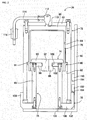
Solder supply device 26 is attached toX-axis slider 60 and is moved to any position abovebase 54 by movingdevice 22. As shown infig. 2 ,solder supply device 26 hassolder cup 70,outer tube 72,supply nozzle 74,inner tube 76, and fixedlid 78.Solder cup 70 is a bottomed cylindrical container with an opening at one end;solder cup 70 is filled with solder paste.Flange section 80 is formed on the outer circumferential surface at the opening side ofsolder cup 70; a screw thread (not shown) is formed betweenflange 80 and the edge of the opening side.Solder cup 70 is sold commercially with a lid (not shown) that engages with the screw thread covering the opening. That is, solder paste manufacturers sellsolder cups 70 after fillingsolder cups 70 with solder paste and covering the opening with a lid. Users purchase solder cups 70 and use them with the lid removed. - Further, ring-shaped
magnet 81 is attached to the outer circumferential section of solder cup 700. In detail, the inside diameter of ring-shapedmagnet 81 is smaller than the outer diameter offlange section 80 ofsolder cup 70, and is larger than the outer diameter of the tubular portion ofsolder container 70 excludingflange section 80. Also,solder cup 70 is engaged with the inside diameter section of ring-shapedmagnet 81 from the bottom surface side ofsolder cup 70. By this,magnet 81 catches onflange section 80 and is thus attached to the outer circumferential section ofsolder cup 70. Note that, the outer diameter ofmagnet 81 is smaller than the outer diameter offlange section 80, such thatmagnet 81 that is caught onflange section 80 does not protrude from the outer edge offlange section 80. - Also,
outer tube 72, similar tosolder cup 70, is a bottomed cylinder with an opening at one end;solder cup 70 is stored insideouter tube 72. In detail, the inner circumferential surface ofouter tube 72 is configured from first innercircumferential surface 82 that is positioned at the opening side ofouter tube 72, and second innercircumferential surface 84 that is positioned atbottom surface 83 ofouter tube 72. The inside diameter of first innercircumferential surface 82 is slightly larger than the outer diameter offlange section 80 ofsolder cup 70; the inside diameter of second innercircumferential surface 84 is slightly larger than the outer diameter of the tubular section ofsolder cup 70. Further, the end of the bottom side ofsolder cup 70 is engaged from the opening ofouter tube 72 such thatsolder cup 70 is stored inouter tube 72. By this,solder cup 70 is slidable insideouter tube 72. - However, the depth dimension of a portion of second inner
circumferential surface 84 ofouter tube 72 is longer than the length dimension frommagnet 81 caught onflange section 80 ofsolder cup 70 to the bottom surface ofsolder cup 70, andmagnet 81 caught onflange section 80 ofsolder cup 70 contacts the step surface between first innercircumferential surface 82 and second innercircumferential surface 84 ofouter tube 72. Therefore,space 86 is formed between the bottom surface ofsolder cup 70 andbottom surface 83 ofouter tube 72. Note that,outer tube 72 is formed from a non-magnetic material such as aluminum. Also note that, herein, the bottom surface refers to the surface on the opposite side to the opening of a bottomed cylindrical member. In other words, even if the surface on the opposite side to the opening of a bottomed cylindrical member is positioned towards the top, and the opening is positioned towards the bottom, the surface on the opposite side to the opening is given as the bottom surface, not the lid. - Also,
supply nozzle 74 is configured fromnozzle section 88 andflange section 90;nozzle section 88 andflange section 90 are formed as one body from material that is elastically deformable.Nozzle section 88 is substantially cylindrical withnozzle hole 92 formed running through the inside.Flange section 90 extends in a disk shape from the outer circumferential surface of an end of the nozzle section; the outer diameter offlange section 90 is slightly larger than the inside diameter ofsolder cup 70. Also,flange section 90 is engaged insidesolder cup 70 such thatnozzle section 88 faces the opening side ofsolder cup 70;supply nozzle 74 slides insidesolder cup 70 with the outer circumferential section offlange section 90 elastically deformed. - Further,
inner tube 76 hascylindrical tube section 96, andring section 98 that covers the edge oftube section 96;supply nozzle 74 is held byring section 98. In detail, the outer circumferential surface ofnozzle section 88 ofsupply nozzle 74 is configured from firstouter surface 100 positioned on theflange section 90 side and second outercircumferential surface 102 positioned at the tip side ofnozzle section 88; the outer diameter of firstouter diameter surface 100 is smaller than the outer diameter of second outercircumferential surface 102. On the other hand, the inside diameter ofring section 98 ofinner tube 76 is slightly larger than the outer diameter of first outercircumferential surface 100 and slightly smaller than the outer diameter of second outercircumferential surface 102. Also,nozzle section 88 engages with the inside diameter section ofring section 98 while a portion of secondcircumferential surface 102 is elastically deformed, and the inside diameter ofring section 98 and outercircumferential surface 100 ofnozzle section 88 engage. By this,inner tube 76 holdssupply nozzle 74 usingring section 98. Note that,inner tube 76 holdssupply nozzle 74 usingring section 98, thereforeinner tube 76 is positioned insidesolder cup 70; however, the end of the side not positioned atring section 98 oftube section 96 extends from the opening ofsolder cup 70. - Also, by pulling
supply nozzle 74 away frominner tube 76, a portion of secondouter circumferential 102 ofnozzle section 88 is elastically deformed such thatsupply nozzle 74 can be removed frominner tube 76. However, the force required to elastically deform the portion of second outercircumferential surface 102 ofnozzle section 88 when removingsupply nozzle 74 frominner tube 76, that is the holding force ofsupply nozzle 74 byinner tube 76, is larger than the friction that arises betweenflange section 90 ofsupply nozzle 74 engaged insidesolder cup 70 and the inner circumferential surface ofsolder cup 70. Thus, wheninner tube 76 holdingsuction nozzle 74 is pulled in a direction away fromsolder cup 70,supply nozzle 74 is not separated frominner tube 76, and is removed fromsolder cup 70 together withinner tube 76. - Further, fixed
lid 78 hasring section 106, and erectedsection 108 established around the entire circumference at the outer edge ofring section 106. A screw thread (not shown) is formed on the inner circumferential surface of erectedsection 108, the screw thread being engaged with the screw thread (not shown) formed at the opening end side ofouter tube 72. By this, fixedlid 78 is removably attached to the opening ofouter tube 72. Also, the inside diameter ofring section 106 is substantially the same as the inside diameter oftube section 96 ofinner tube 76, and the end section that extends fromsolder cup 70 oftube section 96 is fixed to the inside edge ofring section 106. Thus, by removing fixedlid 78 fromouter tube 72,inner tube 76 is also removed from insideouter tube 72. In this case,supply nozzle 74 held byinner tube 76 is also removed from insideouter tube 72. Further,solder cup 70 is also removed fromouter tube 72 by the friction arising betweenflange section 90 ofsupply nozzle 74 and the inner circumferential surface ofsolder cup 70. That is, by removing fixedlid 78 fromouter tube 72,inner tube 76,supply nozzle 74, andsolder cup 70 are removed as one fromouter tube 72. - Also, through-
hole 110 is formed inbottom surface 83 ofouter tube 72, andair adapter 112 is attached in through-hole 110.Air adapter 112 is connected to an end ofair tube 114, and the other end ofair tube 114 is connected to device-side air coupler 116. By connecting slider-side air coupler (refer tofig. 3 ) 118 provided at the arrangement position ofsolder supply device 26 to device-side air coupler 116, air is supplied tospace 86 insideouter tube 72, and solder paste is ejected fromnozzle hole 92 ofsupply nozzle 74. - In detail, as shown in
fig. 3 , an end ofair tube 120 is connected to slider-side air coupler 118, and the other end ofair tube 120 is connected to air supply device (refer tofig. 4 ) 122. By this, air is supplied fromair supply device 122 tospace 86 insideouter tube 72. When air is supplied tospace 86, the bottom surface ofsolder cup 70 is pressed towardssupply nozzle 74 andsolder cup 70 moves down. In this case, the solder paste fillingsolder cup 70 is compressed and is ejected fromnozzle hole 92 ofsupply nozzle 74. Solder paste ejected fromnozzle hole 92 passes throughtube section 96 ofinner tube 76, and the inner section ofring section 106 of fixedlid 78, and is ejected to the outside ofsolder supply device 26. Thus,solder supply device 26 supplies solder paste. - In this way, with
solder supply device 26,space 86 is demarcated by the bottom surface ofsolder cup 70 andbottom surface 83 ofouter tube 72, withspace 86 functioning as an air chamber. That is, by the bottom surface ofsolder cup 70 being directly pressed by air, solder paste insidesolder cup 70 is ejected fromnozzle hole 92. Thus, withsolder supply device 26, it is not necessary to provide a cylinder device or the like for pushingsolder cup 70, andsolder supply device 26 can be made more compact. Also, because there is no need to provide a cylinder device or the like, costs are reduced. Further, because there is no need to provide a cylinder device or the like, the configuration ofsolder supply device 26 can be made simple. - Also, as shown in
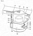
fig. 3 ,solder supply device 26 is detachably mounted onX-axis slider 60 byclip lock 130. In detail,bracket 132 is attached to the lower end ofX-axis slider 60, and the lower surface ofsolder supply device 26 is supported bybracket 132. In other words,solder supply device 26 is able to be loaded onbracket 132. Note that, through-hole (refer tofig. 2 ) 133 approximately the same as the inner diameter ofring section 106 of fixedlid 78 ofsolder supply device 26 is formed inbracket 132. By this, solder paste is supplied fromsolder supply device 26 loaded onbracket 132 via through-hole 133 inbracket 132. - Two surrounding
plates X-axis slider 60 abovebracket 132 facing each other and perpendicular tobracket 132. The distance between the two surroundingbrackets outer tube 72 ofsolder supply device 26, andsolder supply device 26 is loaded between the two surroundingplates closing plate 140 is attached to surroundingplate 134 viahinge 138.Lever section 146 ofclip lock 130 is provided on the other end of opening/closing plate 140, andhook stopper 148 ofclip lock 130 is provided on surroundingplate 136. Also, by performing locking with opening/closing plate 140 in a closed state andlever section 146 latched ontohook stopper 148,solder supply device 26 is fixedly mounted onX-axis slider 60. Also, by releasing the locking ofclip lock 130 and opening opening/closing plate 140,solder supply device 26 is able to be removed fromX-axis slider 60. Note that, device-side air coupler 116 and slider-side air coupler 118 are detachable, and device-side air coupler 116 is removed from slider-side air coupler 118 whensolder supply device 26 is removed fromX-axis slider 60. - Further, as shown in
fig. 2 , twomagnetic sensors X-axis slider 60 so as to face the outer circumferential surface ofouter tube 72 ofsolder supply device 26. Eachmagnetic sensor detection section 154 that detects the approaching ofmagnet 81 todetection section 154. Also, the twomagnetic sensors detection sections 154 of the twomagnetic sensors solder cup 70. - Also, as shown in
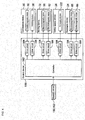
fig. 4 ,solder printer 10 is provided withcontrol device 160.Control device 160 is provided withcontroller 162 andmultiple drive circuits 164.Multiple drive circuits 164 are connected to the above-mentionedelectromagnetic motors device 36, andair supply device 122. Also,controller 162 is provided with a CPU, ROM, RAM, and the like, forming the main parts of a computer, and is connected to themultiple drive circuits 164. Thus, the operation ofconveyance device 20, movingdevice 22,squeegee device 24, andsolder supply device 26 is controlled bycontroller 162. Further,controller 162 is connected tomagnetic sensors magnet 81 frommagnetic sensors - With
solder printer 10, according to the above-described configuration, solder paste is supplied onto the upper surface of a metal mask loaded oncircuit board 34 bysolder supply device 26, and that solder paste is applied bysqueegee device 24. Pattern holes matching the pattern of the pads and so on ofcircuit board 34 are formed in the metal mask, and solder paste is printed ontocircuit board 34 via the pattern holes. - Specifically, based on commands of
controller 162,circuit board 34 is conveyed to a work position, and fixedly held at that position by holdingdevice 36. Then,solder supply device 26, based on commands ofcontroller 162, moves to a prescribed position abovecircuit board 34. Continuing, based on commands ofcontroller 162,solder supply device 26 supplies air fromair supply device 122 intospace 86 insideouter tube 72. By this, solder paste is ejected fromnozzle hole 92, thus supplying solder paste onto the upper surface of the metal mask loaded oncircuit board 34. Next, based on commands ofcontroller 162,squeegee device 24 is moved above the location where solder paste was supplied. Then, based on commands ofcontroller 162,squeegee device 24 moves a squeegee down and then moves in the Y-axis direction. By this, solder paste is applied on the upper surface of the metal mask, and solder paste thus enters into the pattern holes. In this manner,solder printer 10 prints solder paste ontocircuit board 34. - As described above, when printing solder paste onto
circuit board 34, solder paste is supplied fromsolder cup 70 ofsolder supply device 26; thus,solder cup 70 becomes empty andempty solder cup 70 needs to be replaced with asolder cup 70 filled with solder paste. Therefore, withsolder supply device 26, by detecting the approaching ofmagnet 81 usingmagnetic sensors solder cup 70 is small, and that solder insolder cup 70 has run out. - Specifically, when supplying solder using
solder supply device 26, as described above, air is supplied tospace 86 insideouter tube 72 fromair supply device 122. By this, the bottom surface ofsolder cup 70 is pressed towardssupply nozzle 74 andsolder cup 70 moves down. As shown infig. 5 , by this downward movement ofsolder cup 70,magnet 81 facesdetection section 154 ofmagnetic sensor 150 viaouter tube 72. In this case, becauseouter tube 72 is formed from a non-magnetic material, the approaching ofmagnet 81 is detected bydetection section 154 ofmagnetic sensor 150, and a detection signal ofmagnet 81 is entered intocontroller 162 frommagnetic sensor 150. Then,controller 162 displays the fact that the remaining amount of solder insolder cup 70 is small on a display device (not shown). This notifies an operator that soldercup 70 has been lowered to the position shown infig. 5 and that the remaining amount of solder insolder cup 70 is small. - When solder is further supplied from
solder supply device 26,solder cup 70 is lowered further and the bottom surface ofsolder cup 70 contacts supplynozzle 74. In other words,solder cup 70 becomes empty. In this case, as shown infig. 6 ,magnet 81 facesdetection section 154 ofmagnetic sensor 152 viaouter tube 72. By the approaching ofmagnet 81 is detected bydetection section 154 ofmagnetic sensor 152, and a detection signal ofmagnet 81 is entered intocontroller 162 frommagnetic sensor 152. Then,controller 162 displays the fact thatsolder cup 70 is empty on a display device. By this, an operator is informed thatsolder cup 70 is empty, that is, that solder has run out frominside solder cup 70, and thus performssolder cup 70 exchange work. - As described above, with
solder supply device 26, it is possible to notify an operator of the fact that the remaining amount of solder insolder cup 70 is small, thus an operator can perform preparation for solder cup exchange work. Also, an operator is suitably informed when solder has run out, so is able to perform exchange work ofsolder cup 70 promptly. - Further,
magnet 81 used for detecting that solder has run out and so on is ring-shaped, and is attached tosolder cup 70 so as to catch onflange section 80. Thus,magnet 81 is attached tosolder cup 70 without using a tool or the like. This simplifies the construction and lowers costs. - Note that, in the above embodiments,
solder supply device 26 is an example of a solder supply device.Solder cup 70 is an example of a solder container.Outer tube 72 is an example of an outer tube.Flange section 80 is an example of a flange section.Magnet 81 is an example of a magnet.Space 86 is an example of an air chamber.Nozzle section 88 is an example of a nozzle.Flange section 90 is an example of a piston.Magnetic sensors - Further, the present invention is not limited to the above example embodiment, and various changed or improved methods of embodiment are possible based on the knowledge of someone skilled in the art. Specifically, for example, in the above embodiment, a solder supply device that moves
solder cup 70 by supplying air tospace 86 demarcated bysolder cup 70 andouter tube 72 and so on is used; however, a solder supply device that movessolder cup 70 using a drive source such as a cylinder device or electromagnetic motor may be used. - Also, in the above embodiment,
outer tube 72 is formed from non-magnetic material; however, the outer circumferential surface only ofouter tube 72 may be formed from non-magnetic material. Further, the portion ofouter tube 72 that facesmagnetic sensors - Also, in the above embodiment,
magnetic sensors outer tube 72; however,magnetic sensors outer tube 72. In this case, it is not necessary forouter tube 72 to be formed from non-magnetic material. - Also, in the present embodiment, multiple
magnetic sensors - 26: solder supply device; 70: solder cup (solder container); 72: outer tube; 80: flange section; 81: magnet; 86: space (air chamber); 88: nozzle section (nozzle); 90: flange section (piston); 150: magnetic sensor (sensor); 152: magnetic sensor (sensor)
Claims (4)
- A solder supply device (26) comprising:a solder container (70) housing liquid solder that is tubular and open at one end;a nozzle (88), for ejecting solder from the solder container (70), that is inserted into the solder container (70); anda piston (90) that is fixedly provided on an outer circumferential section of the nozzle (88) and that is engaged inside of the solder container (70) from the opening of the solder container (70), wherein the solder supply device (26) supplies solder from the tip of the nozzle (88) by the solder container (70) moving such that the piston (90) advances inside the solder container (70), and wherein the solder supply device (26) includes characterized by:a magnet (81) provided on an outer circumferential surface of the solder container (70), anda sensor (150, 152) provided at a position facing the outer circumferential surface of the solder container (70) so as to detect the approaching of the magnet (81) due to the movement of the solder container (70)the solder supply device (26) is further provided with an outer tube (72) that is tubular with an opening at one end and that stores the solder container (70) in a state with the other end of the solder container (70) engaged from the opening, andthe solder container (70) is moved by air being supplied to an air chamber (86) that is demarcated by the other end of the solder container (70) and the other end of the outer tube (72), so as to supply solder from the tip of the nozzle (88).
- The solder supply device (26) according to claim 1, whereinthe sensor (150, 152) is provided on an outer section of the outer tube (72) and faces the outer circumferential surface of the solder container (70) via the outer tube (72), and at least a portion of the outer tube (72) that faces the sensor (150, 152) is formed from non-magnetic material.
- The solder supply device (26) according to claims 1 or 2, wherein
at least one of the magnet (81) and the sensor (150, 152) are provided in a plural quantity lined up in a movement direction of the solder container (70). - The solder supply device (26) according to any one of the claims 1 to 3, wherein
the solder container (70) has a flange section (80) formed on the outer circumferential section thereof, and
the magnet (81) is a ring-shaped member with an inside diameter that is smaller than the outer diameter of the flange section (80) of the solder container (70), and larger than the outer diameter of the tubular portion of the solder container (70) excluding the flange section (80).
Applications Claiming Priority (1)
| Application Number | Priority Date | Filing Date | Title |
|---|---|---|---|
| PCT/JP2013/083853 WO2015092877A1 (en) | 2013-12-18 | 2013-12-18 | Solder supply device |
Publications (3)
| Publication Number | Publication Date |
|---|---|
| EP3085484A1 EP3085484A1 (en) | 2016-10-26 |
| EP3085484A4 EP3085484A4 (en) | 2018-01-17 |
| EP3085484B1 true EP3085484B1 (en) | 2019-01-30 |
Family
ID=53402272
Family Applications (1)
| Application Number | Title | Priority Date | Filing Date |
|---|---|---|---|
| EP13899803.4A Active EP3085484B1 (en) | 2013-12-18 | 2013-12-18 | Solder supply device |
Country Status (5)
| Country | Link |
|---|---|
| US (1) | US9802264B2 (en) |
| EP (1) | EP3085484B1 (en) |
| JP (1) | JP6243449B2 (en) |
| CN (1) | CN105792972B (en) |
| WO (1) | WO2015092877A1 (en) |
Families Citing this family (8)
| Publication number | Priority date | Publication date | Assignee | Title |
|---|---|---|---|---|
| JP6199988B2 (en) * | 2013-12-05 | 2017-09-20 | 富士機械製造株式会社 | Solder supply device |
| US9878391B2 (en) * | 2014-03-07 | 2018-01-30 | Fuji Machine Mfg. Co., Ltd. | Solder supply device |
| WO2017158813A1 (en) * | 2016-03-18 | 2017-09-21 | 富士機械製造株式会社 | Viscous fluid supply device |
| TWI759460B (en) | 2017-04-14 | 2022-04-01 | 美商伊利諾工具工程公司 | A device for preventing dripping of solder paste |
| TWI755518B (en) * | 2017-04-14 | 2022-02-21 | 美商伊利諾工具工程公司 | An automatic solder paste feeding device and system for a solder paste printing machine |
| CN108724920B (en) * | 2017-04-14 | 2022-03-11 | 伊利诺斯工具制品有限公司 | Device for preventing solder paste from dripping |
| TWI789552B (en) * | 2018-11-26 | 2023-01-11 | 美商伊利諾工具工程公司 | A stencil printer |
| CN112536175B (en) * | 2020-12-07 | 2021-12-14 | 淮北市儒伽医疗科技有限公司 | Paint spraying equipment with impurity removal function |
Family Cites Families (33)
| Publication number | Priority date | Publication date | Assignee | Title |
|---|---|---|---|---|
| US4047645A (en) * | 1976-06-08 | 1977-09-13 | Caliendo Joseph L | Aerosol device with telescoping container parts |
| US4268953A (en) * | 1978-06-05 | 1981-05-26 | Transamerica Delaval Inc. | Method of making an encapsulated magnetic-reed switch circuit element adapted for use in interconnected array |
| JPS5866020A (en) * | 1981-10-15 | 1983-04-20 | Toshiba Corp | Constant quantity discharging device for liquid |
| US4635827A (en) * | 1985-02-06 | 1987-01-13 | Grumman Aerospace Corporation | Sealant applicator for rivet machine |
| US4622239A (en) * | 1986-02-18 | 1986-11-11 | At&T Technologies, Inc. | Method and apparatus for dispensing viscous materials |
| US4720402A (en) * | 1987-01-30 | 1988-01-19 | American Telephone And Telegraph Company | Method for dispensing viscous material |
| US4808435A (en) * | 1987-04-06 | 1989-02-28 | International Business Machines Corporation | Screen printing method for producing lines of uniform width and height |
| US5080864A (en) * | 1990-07-20 | 1992-01-14 | Eastman Kodak Company | Stopper detector |
| JP2503169B2 (en) * | 1992-09-25 | 1996-06-05 | 株式会社テンリュウテクニックス | Dispenser |
| US5376414A (en) * | 1993-06-01 | 1994-12-27 | Sophia Systems Co., Ltd. | Expansion compensated precision extrusion method |
| ES2126768T3 (en) * | 1993-08-20 | 1999-04-01 | Wilhelm A Keller | MEASURING DEVICE FOR MULTIPLE COMPONENTS AND CORRESPONDING DISPENSER WITH FOLDING CONTAINER SETS. |
| JP3263373B2 (en) * | 1998-12-18 | 2002-03-04 | エービービー株式会社 | Automatic coating equipment |
| JP3066963B1 (en) * | 1999-03-31 | 2000-07-17 | インターナショナル・ビジネス・マシーンズ・コーポレ−ション | Method and apparatus for forming solder bumps |
| US6736291B1 (en) * | 1999-05-21 | 2004-05-18 | Matsushita Electric Industrial Co., Ltd. | Viscous material application apparatus |
| US6772937B2 (en) * | 2000-04-24 | 2004-08-10 | Matsushita Electric Industrial Co., Ltd. | Method and apparatus for applying viscous material |
| WO2001093648A2 (en) * | 2000-05-31 | 2001-12-06 | Honeywell International Inc. | Filling device |
| JP2003311930A (en) * | 2002-04-24 | 2003-11-06 | Sony Corp | Solder supply device and solder printing machine |
| JP2004306102A (en) * | 2003-04-08 | 2004-11-04 | Sony Corp | Solder feeder and solder printing machine |
| JP2005096126A (en) * | 2003-09-22 | 2005-04-14 | Sony Corp | Squeegee device and solder printing machine |
| EP1885971A2 (en) * | 2005-05-06 | 2008-02-13 | Stuart Edward Saunders | Tiling adhesive applicator |
| CN100411750C (en) * | 2005-05-20 | 2008-08-20 | 富准精密工业(深圳)有限公司 | Coating device |
| US8684238B2 (en) * | 2008-04-21 | 2014-04-01 | C.H.&I. Technologies, Inc. | Aerosol refill cartridge |
| US9162249B2 (en) * | 2008-10-01 | 2015-10-20 | Panasonic Intellectual Property Management Co., Ltd. | Paste dispenser for applying paste containing fillers using nozzle with pin and application method using the same |
| JP5700951B2 (en) * | 2010-04-27 | 2015-04-15 | 富士機械製造株式会社 | Screen printing machine |
| JP5635879B2 (en) | 2010-11-17 | 2014-12-03 | ヤマハ発動機株式会社 | Adhesive material applicator |
| JP5832864B2 (en) * | 2011-11-14 | 2015-12-16 | 富士機械製造株式会社 | Screen printing machine |
| JP5887488B2 (en) * | 2011-12-16 | 2016-03-16 | パナソニックIpマネジメント株式会社 | Paste supply device and screen printing device |
| JP5887489B2 (en) * | 2011-12-16 | 2016-03-16 | パナソニックIpマネジメント株式会社 | Paste supply device and screen printing device |
| US9278401B2 (en) * | 2013-02-11 | 2016-03-08 | International Business Machines Corporation | Fill head interface with combination vacuum pressure chamber |
| US9878390B2 (en) * | 2013-12-05 | 2018-01-30 | Fuji Machine Mfg. Co. Ltd. | Solder supply device including a solder cup and a nozzle section with a flange section that is elastically deformable |
| JP6199988B2 (en) * | 2013-12-05 | 2017-09-20 | 富士機械製造株式会社 | Solder supply device |
| US9475084B2 (en) * | 2014-12-03 | 2016-10-25 | Nirlat Ltd | Painting apparatus comprising an air bag |
| US10112211B2 (en) * | 2014-12-03 | 2018-10-30 | Nirlat Ltd | Painting apparatus comprising an air bag |
-
2013
- 2013-12-18 JP JP2015553270A patent/JP6243449B2/en active Active
- 2013-12-18 CN CN201380081437.6A patent/CN105792972B/en active Active
- 2013-12-18 EP EP13899803.4A patent/EP3085484B1/en active Active
- 2013-12-18 US US15/100,908 patent/US9802264B2/en active Active
- 2013-12-18 WO PCT/JP2013/083853 patent/WO2015092877A1/en active Application Filing
Non-Patent Citations (1)
| Title |
|---|
| None * |
Also Published As
| Publication number | Publication date |
|---|---|
| EP3085484A1 (en) | 2016-10-26 |
| US20160303675A1 (en) | 2016-10-20 |
| CN105792972B (en) | 2018-09-14 |
| CN105792972A (en) | 2016-07-20 |
| JP6243449B2 (en) | 2017-12-06 |
| EP3085484A4 (en) | 2018-01-17 |
| US9802264B2 (en) | 2017-10-31 |
| JPWO2015092877A1 (en) | 2017-03-16 |
| WO2015092877A1 (en) | 2015-06-25 |
Similar Documents
| Publication | Publication Date | Title |
|---|---|---|
| EP3085484B1 (en) | Solder supply device | |
| EP3078442B1 (en) | Solder supply device | |
| EP3115143B1 (en) | Solder supply apparatus | |
| EP3431191B1 (en) | Viscous fluid supply device | |
| US9883597B2 (en) | Solder supply device including a nozzle with a piston and a demarcating member that demarcates an air chamber in which air is supplied to move the piston relative to a solder container | |
| EP3112071B1 (en) | Solder supply system | |
| US10477750B2 (en) | Component mounting method and component mounting device | |
| US9764543B2 (en) | Paste supply apparatus and screen printing machine | |
| JP2006322359A (en) | Method and system for reducing residual quantity in transfer of viscous fluid | |
| US9393775B2 (en) | Screen printing machine and screen printing method | |
| JP6510109B2 (en) | Solder supply system and solder printing machine | |
| JP6909716B2 (en) | Nozzle device | |
| US20150258775A1 (en) | Paste supply apparatus and screen printing machine | |
| JP2016221574A (en) | Solder supply device |
Legal Events
| Date | Code | Title | Description |
|---|---|---|---|
| PUAI | Public reference made under article 153(3) epc to a published international application that has entered the european phase |
Free format text: ORIGINAL CODE: 0009012 |
|
| 17P | Request for examination filed |
Effective date: 20160614 |
|
| AK | Designated contracting states |
Kind code of ref document: A1 Designated state(s): AL AT BE BG CH CY CZ DE DK EE ES FI FR GB GR HR HU IE IS IT LI LT LU LV MC MK MT NL NO PL PT RO RS SE SI SK SM TR |
|
| AX | Request for extension of the european patent |
Extension state: BA ME |
|
| DAX | Request for extension of the european patent (deleted) | ||
| A4 | Supplementary search report drawn up and despatched |
Effective date: 20171219 |
|
| RIC1 | Information provided on ipc code assigned before grant |
Ipc: B23K 3/06 20060101AFI20171213BHEP Ipc: H05K 3/34 20060101ALI20171213BHEP Ipc: B41F 15/40 20060101ALI20171213BHEP |
|
| STAA | Information on the status of an ep patent application or granted ep patent |
Free format text: STATUS: EXAMINATION IS IN PROGRESS |
|
| 17Q | First examination report despatched |
Effective date: 20180704 |
|
| GRAP | Despatch of communication of intention to grant a patent |
Free format text: ORIGINAL CODE: EPIDOSNIGR1 |
|
| STAA | Information on the status of an ep patent application or granted ep patent |
Free format text: STATUS: GRANT OF PATENT IS INTENDED |
|
| INTG | Intention to grant announced |
Effective date: 20180907 |
|
| RAP1 | Party data changed (applicant data changed or rights of an application transferred) |
Owner name: FUJI CORPORATION |
|
| GRAS | Grant fee paid |
Free format text: ORIGINAL CODE: EPIDOSNIGR3 |
|
| GRAA | (expected) grant |
Free format text: ORIGINAL CODE: 0009210 |
|
| STAA | Information on the status of an ep patent application or granted ep patent |
Free format text: STATUS: THE PATENT HAS BEEN GRANTED |
|
| RIN1 | Information on inventor provided before grant (corrected) |
Inventor name: FUJITA, YOJI |
|
| AK | Designated contracting states |
Kind code of ref document: B1 Designated state(s): AL AT BE BG CH CY CZ DE DK EE ES FI FR GB GR HR HU IE IS IT LI LT LU LV MC MK MT NL NO PL PT RO RS SE SI SK SM TR |
|
| REG | Reference to a national code |
Ref country code: GB Ref legal event code: FG4D |
|
| REG | Reference to a national code |
Ref country code: CH Ref legal event code: EP |
|
| REG | Reference to a national code |
Ref country code: AT Ref legal event code: REF Ref document number: 1092850 Country of ref document: AT Kind code of ref document: T Effective date: 20190215 |
|
| REG | Reference to a national code |
Ref country code: IE Ref legal event code: FG4D |
|
| REG | Reference to a national code |
Ref country code: DE Ref legal event code: R096 Ref document number: 602013050415 Country of ref document: DE |
|
| REG | Reference to a national code |
Ref country code: NL Ref legal event code: FP |
|
| REG | Reference to a national code |
Ref country code: LT Ref legal event code: MG4D |
|
| PG25 | Lapsed in a contracting state [announced via postgrant information from national office to epo] |
Ref country code: PT Free format text: LAPSE BECAUSE OF FAILURE TO SUBMIT A TRANSLATION OF THE DESCRIPTION OR TO PAY THE FEE WITHIN THE PRESCRIBED TIME-LIMIT Effective date: 20190530 Ref country code: ES Free format text: LAPSE BECAUSE OF FAILURE TO SUBMIT A TRANSLATION OF THE DESCRIPTION OR TO PAY THE FEE WITHIN THE PRESCRIBED TIME-LIMIT Effective date: 20190130 Ref country code: NO Free format text: LAPSE BECAUSE OF FAILURE TO SUBMIT A TRANSLATION OF THE DESCRIPTION OR TO PAY THE FEE WITHIN THE PRESCRIBED TIME-LIMIT Effective date: 20190430 Ref country code: LT Free format text: LAPSE BECAUSE OF FAILURE TO SUBMIT A TRANSLATION OF THE DESCRIPTION OR TO PAY THE FEE WITHIN THE PRESCRIBED TIME-LIMIT Effective date: 20190130 Ref country code: FI Free format text: LAPSE BECAUSE OF FAILURE TO SUBMIT A TRANSLATION OF THE DESCRIPTION OR TO PAY THE FEE WITHIN THE PRESCRIBED TIME-LIMIT Effective date: 20190130 Ref country code: SE Free format text: LAPSE BECAUSE OF FAILURE TO SUBMIT A TRANSLATION OF THE DESCRIPTION OR TO PAY THE FEE WITHIN THE PRESCRIBED TIME-LIMIT Effective date: 20190130 Ref country code: PL Free format text: LAPSE BECAUSE OF FAILURE TO SUBMIT A TRANSLATION OF THE DESCRIPTION OR TO PAY THE FEE WITHIN THE PRESCRIBED TIME-LIMIT Effective date: 20190130 |
|
| REG | Reference to a national code |
Ref country code: AT Ref legal event code: MK05 Ref document number: 1092850 Country of ref document: AT Kind code of ref document: T Effective date: 20190130 |
|
| PG25 | Lapsed in a contracting state [announced via postgrant information from national office to epo] |
Ref country code: BG Free format text: LAPSE BECAUSE OF FAILURE TO SUBMIT A TRANSLATION OF THE DESCRIPTION OR TO PAY THE FEE WITHIN THE PRESCRIBED TIME-LIMIT Effective date: 20190430 Ref country code: HR Free format text: LAPSE BECAUSE OF FAILURE TO SUBMIT A TRANSLATION OF THE DESCRIPTION OR TO PAY THE FEE WITHIN THE PRESCRIBED TIME-LIMIT Effective date: 20190130 Ref country code: IS Free format text: LAPSE BECAUSE OF FAILURE TO SUBMIT A TRANSLATION OF THE DESCRIPTION OR TO PAY THE FEE WITHIN THE PRESCRIBED TIME-LIMIT Effective date: 20190530 Ref country code: LV Free format text: LAPSE BECAUSE OF FAILURE TO SUBMIT A TRANSLATION OF THE DESCRIPTION OR TO PAY THE FEE WITHIN THE PRESCRIBED TIME-LIMIT Effective date: 20190130 Ref country code: GR Free format text: LAPSE BECAUSE OF FAILURE TO SUBMIT A TRANSLATION OF THE DESCRIPTION OR TO PAY THE FEE WITHIN THE PRESCRIBED TIME-LIMIT Effective date: 20190501 Ref country code: RS Free format text: LAPSE BECAUSE OF FAILURE TO SUBMIT A TRANSLATION OF THE DESCRIPTION OR TO PAY THE FEE WITHIN THE PRESCRIBED TIME-LIMIT Effective date: 20190130 |
|
| PG25 | Lapsed in a contracting state [announced via postgrant information from national office to epo] |
Ref country code: RO Free format text: LAPSE BECAUSE OF FAILURE TO SUBMIT A TRANSLATION OF THE DESCRIPTION OR TO PAY THE FEE WITHIN THE PRESCRIBED TIME-LIMIT Effective date: 20190130 Ref country code: SK Free format text: LAPSE BECAUSE OF FAILURE TO SUBMIT A TRANSLATION OF THE DESCRIPTION OR TO PAY THE FEE WITHIN THE PRESCRIBED TIME-LIMIT Effective date: 20190130 Ref country code: CZ Free format text: LAPSE BECAUSE OF FAILURE TO SUBMIT A TRANSLATION OF THE DESCRIPTION OR TO PAY THE FEE WITHIN THE PRESCRIBED TIME-LIMIT Effective date: 20190130 Ref country code: EE Free format text: LAPSE BECAUSE OF FAILURE TO SUBMIT A TRANSLATION OF THE DESCRIPTION OR TO PAY THE FEE WITHIN THE PRESCRIBED TIME-LIMIT Effective date: 20190130 Ref country code: AL Free format text: LAPSE BECAUSE OF FAILURE TO SUBMIT A TRANSLATION OF THE DESCRIPTION OR TO PAY THE FEE WITHIN THE PRESCRIBED TIME-LIMIT Effective date: 20190130 Ref country code: DK Free format text: LAPSE BECAUSE OF FAILURE TO SUBMIT A TRANSLATION OF THE DESCRIPTION OR TO PAY THE FEE WITHIN THE PRESCRIBED TIME-LIMIT Effective date: 20190130 |
|
| REG | Reference to a national code |
Ref country code: DE Ref legal event code: R097 Ref document number: 602013050415 Country of ref document: DE |
|
| PG25 | Lapsed in a contracting state [announced via postgrant information from national office to epo] |
Ref country code: SM Free format text: LAPSE BECAUSE OF FAILURE TO SUBMIT A TRANSLATION OF THE DESCRIPTION OR TO PAY THE FEE WITHIN THE PRESCRIBED TIME-LIMIT Effective date: 20190130 |
|
| PLBE | No opposition filed within time limit |
Free format text: ORIGINAL CODE: 0009261 |
|
| STAA | Information on the status of an ep patent application or granted ep patent |
Free format text: STATUS: NO OPPOSITION FILED WITHIN TIME LIMIT |
|
| PG25 | Lapsed in a contracting state [announced via postgrant information from national office to epo] |
Ref country code: AT Free format text: LAPSE BECAUSE OF FAILURE TO SUBMIT A TRANSLATION OF THE DESCRIPTION OR TO PAY THE FEE WITHIN THE PRESCRIBED TIME-LIMIT Effective date: 20190130 |
|
| 26N | No opposition filed |
Effective date: 20191031 |
|
| PG25 | Lapsed in a contracting state [announced via postgrant information from national office to epo] |
Ref country code: SI Free format text: LAPSE BECAUSE OF FAILURE TO SUBMIT A TRANSLATION OF THE DESCRIPTION OR TO PAY THE FEE WITHIN THE PRESCRIBED TIME-LIMIT Effective date: 20190130 |
|
| PG25 | Lapsed in a contracting state [announced via postgrant information from national office to epo] |
Ref country code: TR Free format text: LAPSE BECAUSE OF FAILURE TO SUBMIT A TRANSLATION OF THE DESCRIPTION OR TO PAY THE FEE WITHIN THE PRESCRIBED TIME-LIMIT Effective date: 20190130 |
|
| REG | Reference to a national code |
Ref country code: CH Ref legal event code: PL |
|
| REG | Reference to a national code |
Ref country code: BE Ref legal event code: MM Effective date: 20191231 |
|
| PG25 | Lapsed in a contracting state [announced via postgrant information from national office to epo] |
Ref country code: MC Free format text: LAPSE BECAUSE OF FAILURE TO SUBMIT A TRANSLATION OF THE DESCRIPTION OR TO PAY THE FEE WITHIN THE PRESCRIBED TIME-LIMIT Effective date: 20190130 |
|
| PG25 | Lapsed in a contracting state [announced via postgrant information from national office to epo] |
Ref country code: LU Free format text: LAPSE BECAUSE OF NON-PAYMENT OF DUE FEES Effective date: 20191218 Ref country code: IE Free format text: LAPSE BECAUSE OF NON-PAYMENT OF DUE FEES Effective date: 20191218 |
|
| PG25 | Lapsed in a contracting state [announced via postgrant information from national office to epo] |
Ref country code: LI Free format text: LAPSE BECAUSE OF NON-PAYMENT OF DUE FEES Effective date: 20191231 Ref country code: CH Free format text: LAPSE BECAUSE OF NON-PAYMENT OF DUE FEES Effective date: 20191231 Ref country code: BE Free format text: LAPSE BECAUSE OF NON-PAYMENT OF DUE FEES Effective date: 20191231 |
|
| PG25 | Lapsed in a contracting state [announced via postgrant information from national office to epo] |
Ref country code: CY Free format text: LAPSE BECAUSE OF FAILURE TO SUBMIT A TRANSLATION OF THE DESCRIPTION OR TO PAY THE FEE WITHIN THE PRESCRIBED TIME-LIMIT Effective date: 20190130 |
|
| PG25 | Lapsed in a contracting state [announced via postgrant information from national office to epo] |
Ref country code: MT Free format text: LAPSE BECAUSE OF FAILURE TO SUBMIT A TRANSLATION OF THE DESCRIPTION OR TO PAY THE FEE WITHIN THE PRESCRIBED TIME-LIMIT Effective date: 20190130 Ref country code: HU Free format text: LAPSE BECAUSE OF FAILURE TO SUBMIT A TRANSLATION OF THE DESCRIPTION OR TO PAY THE FEE WITHIN THE PRESCRIBED TIME-LIMIT; INVALID AB INITIO Effective date: 20131218 |
|
| PG25 | Lapsed in a contracting state [announced via postgrant information from national office to epo] |
Ref country code: MK Free format text: LAPSE BECAUSE OF FAILURE TO SUBMIT A TRANSLATION OF THE DESCRIPTION OR TO PAY THE FEE WITHIN THE PRESCRIBED TIME-LIMIT Effective date: 20190130 |
|
| P01 | Opt-out of the competence of the unified patent court (upc) registered |
Effective date: 20230328 |
|
| PGFP | Annual fee paid to national office [announced via postgrant information from national office to epo] |
Ref country code: NL Payment date: 20231116 Year of fee payment: 11 |
|
| PGFP | Annual fee paid to national office [announced via postgrant information from national office to epo] |
Ref country code: GB Payment date: 20231102 Year of fee payment: 11 |
|
| PGFP | Annual fee paid to national office [announced via postgrant information from national office to epo] |
Ref country code: IT Payment date: 20231110 Year of fee payment: 11 Ref country code: FR Payment date: 20231108 Year of fee payment: 11 Ref country code: DE Payment date: 20231031 Year of fee payment: 11 |