EP3085469A1 - Method for manufacturing molded material, and surface-treated metal plate used therein - Google Patents
Method for manufacturing molded material, and surface-treated metal plate used therein Download PDFInfo
- Publication number
- EP3085469A1 EP3085469A1 EP14871623.6A EP14871623A EP3085469A1 EP 3085469 A1 EP3085469 A1 EP 3085469A1 EP 14871623 A EP14871623 A EP 14871623A EP 3085469 A1 EP3085469 A1 EP 3085469A1
- Authority
- EP
- European Patent Office
- Prior art keywords
- ironing
- formed portion
- metal plate
- peripheral surface
- punch
- Prior art date
- Legal status (The legal status is an assumption and is not a legal conclusion. Google has not performed a legal analysis and makes no representation as to the accuracy of the status listed.)
- Granted
Links
Images


Classifications
-
- B—PERFORMING OPERATIONS; TRANSPORTING
- B21—MECHANICAL METAL-WORKING WITHOUT ESSENTIALLY REMOVING MATERIAL; PUNCHING METAL
- B21D—WORKING OR PROCESSING OF SHEET METAL OR METAL TUBES, RODS OR PROFILES WITHOUT ESSENTIALLY REMOVING MATERIAL; PUNCHING METAL
- B21D22/00—Shaping without cutting, by stamping, spinning, or deep-drawing
- B21D22/20—Deep-drawing
- B21D22/28—Deep-drawing of cylindrical articles using consecutive dies
- B21D22/286—Deep-drawing of cylindrical articles using consecutive dies with lubricating or cooling means
-
- B—PERFORMING OPERATIONS; TRANSPORTING
- B21—MECHANICAL METAL-WORKING WITHOUT ESSENTIALLY REMOVING MATERIAL; PUNCHING METAL
- B21D—WORKING OR PROCESSING OF SHEET METAL OR METAL TUBES, RODS OR PROFILES WITHOUT ESSENTIALLY REMOVING MATERIAL; PUNCHING METAL
- B21D22/00—Shaping without cutting, by stamping, spinning, or deep-drawing
- B21D22/20—Deep-drawing
- B21D22/28—Deep-drawing of cylindrical articles using consecutive dies
-
- B—PERFORMING OPERATIONS; TRANSPORTING
- B21—MECHANICAL METAL-WORKING WITHOUT ESSENTIALLY REMOVING MATERIAL; PUNCHING METAL
- B21D—WORKING OR PROCESSING OF SHEET METAL OR METAL TUBES, RODS OR PROFILES WITHOUT ESSENTIALLY REMOVING MATERIAL; PUNCHING METAL
- B21D51/00—Making hollow objects
- B21D51/02—Making hollow objects characterised by the structure of the objects
- B21D51/10—Making hollow objects characterised by the structure of the objects conically or cylindrically shaped objects
-
- C—CHEMISTRY; METALLURGY
- C23—COATING METALLIC MATERIAL; COATING MATERIAL WITH METALLIC MATERIAL; CHEMICAL SURFACE TREATMENT; DIFFUSION TREATMENT OF METALLIC MATERIAL; COATING BY VACUUM EVAPORATION, BY SPUTTERING, BY ION IMPLANTATION OR BY CHEMICAL VAPOUR DEPOSITION, IN GENERAL; INHIBITING CORROSION OF METALLIC MATERIAL OR INCRUSTATION IN GENERAL
- C23C—COATING METALLIC MATERIAL; COATING MATERIAL WITH METALLIC MATERIAL; SURFACE TREATMENT OF METALLIC MATERIAL BY DIFFUSION INTO THE SURFACE, BY CHEMICAL CONVERSION OR SUBSTITUTION; COATING BY VACUUM EVAPORATION, BY SPUTTERING, BY ION IMPLANTATION OR BY CHEMICAL VAPOUR DEPOSITION, IN GENERAL
- C23C2/00—Hot-dipping or immersion processes for applying the coating material in the molten state without affecting the shape; Apparatus therefor
- C23C2/04—Hot-dipping or immersion processes for applying the coating material in the molten state without affecting the shape; Apparatus therefor characterised by the coating material
- C23C2/06—Zinc or cadmium or alloys based thereon
Definitions
- Present invention relates to a formed material manufacturing method in which ironing is performed on a formed portion, and a surface treated metal plate used therein.
- a convex formed portion is typically formed by performing a pushing process such as drawing using a surface treated metal plate such as a coated steel plate as a raw material.
- ironing is implemented on the formed portion after the formed portion is formed. Ironing is a processing method of setting a clearance between a punch and a die to be narrower than a plate thickness of the formed portion prior to ironing, and then ironing a plate surface of the formed portion using the punch and the die so that the plate thickness of the formed portion matches the clearance between the punch and the die.
- the conventional mold includes a punch and a die.
- the punch is a columnar member having an outer peripheral surface that extends rectilinearly parallel to a pushing direction into a pushing hole, and is inserted into a formed portion.
- the die includes the pushing hole into which the formed portion is pushed together with the punch.
- the pushing hole has a shoulder portion disposed on an outer edge of an inlet of the pushing hole and constituted by a curved surface having a predetermined curvature radius, and an inner peripheral surface that extends rectilinearly from a radius end of the shoulder portion parallel to the pushing direction.
- the plate thickness of the formed portion prior to ironing is uneven in the pushing direction. More specifically, the plate thickness of a rear end side of the formed portion in the pushing direction is often thicker than the plate thickness of a tip end side of the formed portion. The reason why the rear end side is thicker is that when the formed portion is formed, the tip end side is stretched to a greater extent than the rear end side.
- the outer peripheral surface of the punch and the inner peripheral surface of the pushing hole extend parallel to each other. Accordingly, the clearance between the outer peripheral surface of the punch and the inner peripheral surface of the pushing hole is uniform in the pushing direction, and therefore the part of the formed portion having the increased plate thickness is subjected to a larger amount of ironing. Hence, a surface treated layer of the part having the increased plate thickness is shaved, and as a result, a powder form residue may be generated.
- the powder form residue causes problems such as formation of minute pockmarks (dents) in the surface of the ironed formed portion and deterioration of the performance of a product manufactured using the formed material.
- Present invention has been designed to solve the problem described above, and an object thereof is to provide a formed material manufacturing method and a surface treated metal plate used therein, with which generation of a large load on a part of a surface can be avoided so that an amount of generated powder form residue can be reduced.
- a formed material manufacturing method includes the steps of: forming a convex formed portion by performing at least one forming process on a surface treated metal plate; and performing ironing on the formed portion using an ironing mold after forming the formed portion.
- the surface treated metal plate includes a surface treated layer provided on a surface of the metal plate, and a lubricating film provided on a surface of the surface treated layer.
- the ironing mold includes a punch that is inserted into the formed portion, and a die having a pushing hole into which the formed portion is pushed together with the punch.
- the pushing hole includes a shoulder portion disposed on an outer edge of an inlet of the pushing hole and constituted by a curved surface having a predetermined curvature radius, and an inner peripheral surface which extends from a radius end of the shoulder portion in a pushing direction of the formed portion, and along which an outer surface of the formed portion slides in response to relative displacement between the punch and the die.
- the inner peripheral surface extends non-parallel to an outer peripheral surface of the punch, and the inner peripheral surface is provided with a clearance that corresponds to an uneven plate thickness distribution, in the pushing direction, of the formed portion prior to the ironing relative to the outer peripheral surface to ensure that an amount of ironing applied to the formed portion remains constant in the pushing direction.
- a surface treated metal plate according to present invention is used in a formed material manufacturing method including the steps of forming a convex formed portion by performing at least one forming process on the surface treated metal plate, and performing ironing on the formed portion using an ironing mold after forming the formed portion, and includes a surface treated layer provided on a surface of the metal plate and a lubricating film provided on a surface of the surface treated layer.
- the inner peripheral surface of the pushing hole extends non-parallel to the outer peripheral surface of the punch, and the inner peripheral surface is provided with a clearance that corresponds to the uneven plate thickness distribution, in the pushing direction, of the formed portion prior to the ironing relative to the outer peripheral surface to ensure that the amount of ironing applied to the formed portion remains constant in the pushing direction. Therefore, generation of a large load on a part of the surface can be avoided, and as a result, an amount of generated powder form residue can be reduced.
- the surface treated metal plate includes the surface treated layer provided on the surface of the metal plate and the lubricating film provided on the surface of the surface treated layer, and therefore the amount of generated powder form residue can be reduced under a wider range of processing conditions.
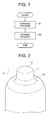
- Fig. 1 is a flowchart showing a formed material manufacturing method according to an embodiment of the present invention.
- Fig. 2 is a perspective view showing a formed material including a formed portion 1 formed by a forming process S1 shown in Fig. 1 .
- Fig. 3 is a perspective view showing the formed material including the formed portion 1 following an ironing process S2 shown in Fig. 1 .
- the formed material manufacturing method includes the forming process S1 and the ironing process S2.
- the forming process S1 is a process for forming the formed portion 1 (see Fig. 2 ) in a convex shape by performing at least one forming process on a surface treated metal plate.
- the forming process includes a pressing process such as drawing or stretching.
- the surface treated metal plate includes a surface treated layer provided on a surface of the metal plate, and a lubricating film provided on a surface of the surface treated layer.
- the surface treated layer includes a coating film or a coating layer.
- the lubricating film is a resin coating film formed by dispersing a compound of polyethylene-fluorine resin particles over the surface of the surface treated layer as a lubricant, the polyethylene-fluorine resin particles being obtained by bonding fine fluorine resin powder to the particle surface of polyethylene resin powder and polyethylene resin particles, for example.
- the surface treated metal plate will be described as a Zn (zinc) coated steel plate obtained by applying a Zn coating to the surface of a steel plate and then forming the lubricating film on the surface of the coating layer.
- the formed portion 1 is a convex portion formed by forming the Zn coated steel plate into a cap body and then forming an apex portion of the cap body to project further therefrom.
- a direction extending from a base portion 1b to an apex portion 1a of the formed portion 1 will be referred to as a pushing direction 1c.
- the pushing direction 1c is a direction in which the formed portion 1 is pushed into a pushing hole (see Fig. 5 ) provided in a die of an ironing mold to be described below.
- the ironing process S2 is a process for performing ironing on the formed portion 1 using the ironing mold to be described below.
- Ironing is a processing method of setting a clearance between a punch and a die of an ironing mold to be narrower than a plate thickness of a formed portion prior to ironing, and then ironing a plate surface of the formed portion using the punch and the die so that the plate thickness of the formed portion matches the clearance between the punch and the die.
- the thickness of the formed portion 1 following ironing is thinner than the thickness of the formed portion 1 prior to ironing.
- a formed material manufactured by performing the forming process S1 and the ironing process S2, or in other words a formed material manufactured using the formed material manufacturing method according to this embodiment can be used in various applications, but is used in particular in an application as a motor case or the like, for example, in which the formed portion 1 requires a high degree of dimensional precision.
- Fig. 4 is a sectional view showing the formed portion 1 of Fig. 2 .
- the plate thickness of the formed portion 1 prior to ironing is uneven in the pushing direction 1c. More specifically, the plate thickness on the base portion 1b side of the formed portion 1 in the pushing direction 1c is thicker than the plate thickness on the apex portion 1a side of the formed portion 1. In other words, the plate thickness of the formed portion 1 decreases gradually in the pushing direction 1c from a rear end side (the base portion 1b side) toward a tip end side (the apex portion 1a side) .
- a plate thickness reduction rate may be constant or uneven in the pushing direction 1c.
- Fig. 5 is a sectional view showing an ironing mold 2 used in the ironing process S2 shown in Fig. 1
- Fig. 6 is an enlarged illustrative view showing a periphery of a shoulder portion 211 during the ironing process performed on the formed portion using the ironing mold 2 shown in Fig. 5
- the ironing mold 2 includes a punch 20 and a die 21.
- the punch 20 is a convex body that is inserted into the formed portion 1 described above.
- An outer peripheral surface 20a of the punch 20 extends rectilinearly parallel to the pushing direction 1c into a pushing hole 210.
- the die 21 is a member that includes the pushing hole 210 into which the formed portion 1 is pushed together with the punch 20.
- the pushing hole 210 includes the shoulder portion 211 and an inner peripheral surface 212.
- the shoulder portion 211 is disposed on an outer edge of an inlet of the pushing hole 210, and is constituted by a curved surface having a predetermined curvature radius.
- the inner peripheral surface 212 is a wall surface extending in the pushing direction 1c from a radius end 211a of the shoulder portion 211.
- the radius end 211a of the shoulder portion 211 is a terminal end of the curved surface constituting the shoulder portion 211 on an inner side of the pushing hole 210.
- the point that the inner peripheral surface 212 extends in the pushing direction 1c means that a component of the pushing direction 1c is included in an extension direction of the inner peripheral surface 212.
- the inner peripheral surface 212 of the pushing hole 210 extends non-parallel (does not extend parallel) to the outer peripheral surface 20a of the punch 20.
- the formed portion 1 When the formed portion 1 is pushed into the pushing hole 210 together with the punch 20, as shown in Fig. 6 , a plate surface of the formed portion 1 is ironed by the shoulder portion 211. Further, an outer surface of the formed portion 1 slides along the inner peripheral surface 212 in response to relative displacement between the punch 20 and the die 21.
- the inner peripheral surface 212 extends non-parallel to the outer peripheral surface 20a of the punch 20, and therefore the inner peripheral surface 212 also irons (thins) the plate surface of the formed portion 1.
- the inner peripheral surface 212 is provided with a clearance 212a that corresponds to the uneven plate thickness distribution, in the pushing direction 1c, of the formed portion 1 prior to ironing relative to the outer peripheral surface 20a of the punch 20.
- the clearance 212a is a clearance between the inner peripheral surface 212 and the outer peripheral surface 20a at a point where the punch 20 is pushed into the pushing hole 210 up to a completion position of the ironing.
- the inner peripheral surface 212 is provided such that the clearance 212a relative to the outer peripheral surface 20a in any position in the pushing direction 1c takes a value obtained by subtracting a fixed value (the required ironing amount) from the plate thickness of the formed portion 1 prior to ironing in an identical position.
- the clearance 212a in any position in the pushing direction 1c is set as C (d)
- the plate thickness of the formed portion 1 prior to ironing in the same position is set as T b (d)
- the required ironing amount is set as A
- d is the distance from the base portion 1b of the formed portion 1 in the pushing direction 1c.
- the inner peripheral surface 212 is provided such that the clearance 212a between the inner peripheral surface 212 and the outer peripheral surface 20a decreases in the pushing direction 1c at an identical rate to the reduction rate of the plate thickness of the formed portion 1 in the pushing direction 1c prior to ironing.
- the inner peripheral surface 212 is constituted by a rectilinear tapered surface that extends at an angle corresponding to the reduction rate of the plate thickness of the formed portion 1.
- the reduction rate of the plate thickness of the formed portion 1 in the pushing direction 1c prior to ironing is uneven, on the other hand, the reduction rate of the plate thickness of the formed portion 1 is approximated to a fixed value, and the inner peripheral surface 212 is formed as a tapered surface that extends at an angle corresponding to the approximated value.
- FIG. 7 is a schematic illustrative view showing a relationship between the shoulder portion 211 of Fig. 6 and a coating layer 10 of a Zn coated steel plate.
- minute irregularities 10a exist on a surface of the coating layer 10 of the Zn coated steel plate. Without a lubricating film, when the plate surface of the formed portion 1 is ironed by the shoulder portion 211 as shown in Fig. 6 , the irregularities 10a may be shaved by the shoulder portion 211 so as to form ironing residue.
- the amount of generated coating residue correlates with a ratio r/t between a curvature radius r of the shoulder portion 211 and a plate thickness t of the Zn coated steel plate.
- a ratio r/t between a curvature radius r of the shoulder portion 211 and a plate thickness t of the Zn coated steel plate.
- the curvature radius r of the shoulder portion 211 decreases, local skewness increases, leading to an increase in sliding resistance between the surface of the coating layer 10 and the shoulder portion 211, and as a result, the amount of generated coating residue increases.
- the plate thickness t of the Zn coated steel plate increases, an amount of thinning performed by the shoulder portion 211 increases, leading to an increase in a load exerted on the surface of the Zn coated steel plate, and as a result, the amount of generated coating residue increases.
- the amount of generated coating residue increases as the ratio r/t decreases and decreases as the ratio r/t increases.
- the coating surface is covered by a lubricating film, on the other hand, sliding resistance between the surface of the coating layer 10 and the shoulder portion 211 decreases, and therefore the ratio r/t at which coating residue is generated takes a smaller value than in a condition where a lubricating film is not provided.
- the plate surface of the pre-ironing formed portion 1 in a position sandwiched between the radius end 211a and the punch 20 upon completion of the ironing is thinned to the largest extent by the shoulder portion 211.
- the amount of generated coating residue correlates strongly with a ratio r/t re between the curvature radius r of the shoulder portion 211 and a plate thickness t re of the pre-ironing formed portion 1 in the position sandwiched between the radius end 211a and the punch 20 upon completion of the ironing.
- the amount of generated coating residue also correlates with an ironing rate applied by the shoulder portion 211.
- the ironing rate is expressed by ⁇ (t re - c re ) / t re ⁇ ⁇ 100.
- the clearance c re corresponds to the plate thickness of the post-ironing formed portion 1 in the position sandwiched between the radius end 211a and the punch 20.
- Fig. 8 is a graph showing a skewness Rsk of the coating layer 10 shown in Fig. 6 in relation to various types of coating layers. The amount of generated coating residue also correlates with the skewness Rsk of the coating layer 10.
- the skewness Rsk represents an existence probability of projecting portions among the irregularities 10a (see Fig. 7 ) on the coating layer 10. As the skewness Rsk decreases, the number of projecting portions decreases, and therefore the amount of generated coating residue is suppressed. Note that the skewness Rsk has been described by the present applicant in Japanese Patent Application Publication 2006-193776 .
- a Zn-Al-Mg alloy coated steel plate, a hot dip galvannealed steel plate, a hot dip galvanized steel plate, and an electro-galvanized steel plate may be cited as types of Zn coated steel plates.
- a typical Zn-Al-Mg alloy coated steel plate is formed by applying a coating layer constituted by an alloy containing Zn, 6% by weight of Al (aluminum), and 3% by weight of Mg (magnesium) to the surface of a steel plate.
- a coating layer constituted by an alloy containing Zn, 6% by weight of Al (aluminum), and 3% by weight of Mg (magnesium)
- the present applicant learned, after investigating the respective skewnesses Rsk of these materials, that the skewness Rsk of the Zn-Al-Mg alloy coated steel plate is included within a range of less than -0.6 and no less than -1.3, while the skewnesses Rsk of the other coated steel plates are included within a range of no less than -0.6 and no more than 0.
- the inventors performed ironing on a Zn-Al-Mg alloy coated steel plate under following conditions while modifying the ironing rate and r/t re .
- a steel plate not having a lubricating film (a comparative example) and a steel plate having a lubricating film (an example of the invention) were both used as the Zn-Al-Mg alloy coated steel plate.
- a plate thickness of the Zn-Al-Mg alloy coated steel plate was set at 1.8 mm, and a coating coverage was set at 90 g/m 2 .
- Table 1 Chemical composition of sample (% by weight) Coating type C Si Mn P S Al Ti Zn-Al-Mg alloy coated steel plate 0.002 0.006 0.14 0.014 0.006 0.032 0.056 [Table 2] Table 2: Mechanical properties of sample Coating type Yield strength (N/mm 2 ) Tensile strength (N/mm 2 ) Elongation (%) Hardness Hv Zn-Al-Mg alloy coated steel plate 164 304 49.2 87 [Table 3] Table 3: Experiment conditions Pressing device 2500 kN Transfer Press Height of pre-ironing formed portion 10.5 to 13.5 mm Curvature radius r of shoulder portion of forming mold 1.5 to 4.5 mm Curvature radius r of shoulder portion of ironing mold 0.3 to 2.0 mm Clearance of ironing mold 1.10 to 1.80 mm Press forming oil TN-20 (manufactured by Tokyo Sekiyu Company Ltd.)
- the ordinate in Fig. 9 is the ironing rate, which is expressed by ⁇ (t re - c re ) / t re ⁇ ⁇ 100, and the abscissa is the ratio between the curvature radius r of the shoulder portion 211 and the plate thickness t re of the pre-ironing formed portion 1 in the position sandwiched between the radius end 211a and the punch 20 upon completion of the ironing, which is expressed by r/t re .
- Circles show evaluations according to which it was possible to suppress coating residue generation, and crosses show evaluations according to which coating residue generation could not be suppressed. Further, black circles show results according to which the dimensional precision deviated from a predetermined range.
- Y 6.0X - 3.2
- Y 14.5X - 4.6
- Y the ironing rate
- X is r/t re
- Y 15.0X - 3.8
- the present inventors performed a similar experiment under conditions described below in relation to the hot dip galvannealed steel plate, the hot dip galvanized steel plate, and the electro-galvanized steel plate.
- experiment conditions such as the pressing device (see Table 3) were identical to those of the ironing performed on the Zn-Al-Mg alloy coated steel plate, described above. Further, the hot dip galvannealed steel plate and the hot dip galvanized steel plate had a plate thickness of 1.8 mm and a coating coverage of 90 g/m 2 , while the electro-galvanized steel plate had a plate thickness of 1.8 mm and a coating coverage of 20 g/m 2 .
- Table 4 Chemical composition of samples (% by weight) Coating type C Si Mn P S Al Ti Hot dip galvannealed steel plate 0.003 0.005 0.14 0.014 0.006 0.035 0.070 Hot dip galvanized steel plate 0.004 0.006 0.15 0.014 0.007 0.039 0.065 Electro-galvanized steel plate 0.002 0.004 0.13 0.013 0.008 0.041 0.071 [Table 5] Table 5: Mechanical properties of samples Coating type Yield strength (N/mm 2 ) Tensile strength (N/mm 2 ) Elongation (%) Hardness Hv Hot dip galvannealed steel plate 175 315 46.2 89 Hot dip galvanized steel plate 178 318 45.7 90 Electro-galvanized steel plate 159 285 53.4 84
- the inner peripheral surface 212 is provided with the clearance 212a that corresponds to the uneven plate thickness distribution, in the pushing direction 1c, of the formed portion 1 prior to ironing relative to the outer peripheral surface 20a of the punch 20, and therefore generation of a large load in a part of the surface can be avoided, with the result that the amount of generated powder form residue can be reduced.
- the thickness of the lubricating film is set to be thicker than 0.2 ⁇ m and thinner than 1.8 ⁇ m, and therefore the amount of generated powder form residue can be reduced more reliably under a wider range of processing conditions.
- the thickness of the lubricating film is set to be no less than 0.5 ⁇ m and no more than 1.2 ⁇ m, and therefore the amount of generated powder form residue can be reduced even more reliably under an even wider range of processing conditions.
Landscapes
- Engineering & Computer Science (AREA)
- Mechanical Engineering (AREA)
- Shaping Metal By Deep-Drawing, Or The Like (AREA)
- Forging (AREA)
Abstract
Description
- Present invention relates to a formed material manufacturing method in which ironing is performed on a formed portion, and a surface treated metal plate used therein.
- A convex formed portion is typically formed by performing a pushing process such as drawing using a surface treated metal plate such as a coated steel plate as a raw material. When the formed portion requires a particularly high degree of dimensional precision, ironing is implemented on the formed portion after the formed portion is formed. Ironing is a processing method of setting a clearance between a punch and a die to be narrower than a plate thickness of the formed portion prior to ironing, and then ironing a plate surface of the formed portion using the punch and the die so that the plate thickness of the formed portion matches the clearance between the punch and the die.
- A configuration disclosed in
Patent Document 1 and so on, shown below, for example, may be employed as a mold used during ironing. Specifically, the conventional mold includes a punch and a die. The punch is a columnar member having an outer peripheral surface that extends rectilinearly parallel to a pushing direction into a pushing hole, and is inserted into a formed portion. The die includes the pushing hole into which the formed portion is pushed together with the punch. The pushing hole has a shoulder portion disposed on an outer edge of an inlet of the pushing hole and constituted by a curved surface having a predetermined curvature radius, and an inner peripheral surface that extends rectilinearly from a radius end of the shoulder portion parallel to the pushing direction. When the formed portion is pushed into the pushing hole, the plate surface thereof is ironed by the shoulder portion so as to decrease gradually in thickness to a width of a clearance between the outer peripheral surface of the punch and the inner peripheral surface of the pushing hole. -
- [PTL 1] Japanese Patent Application Publication
H5-50151 - The plate thickness of the formed portion prior to ironing is uneven in the pushing direction. More specifically, the plate thickness of a rear end side of the formed portion in the pushing direction is often thicker than the plate thickness of a tip end side of the formed portion. The reason why the rear end side is thicker is that when the formed portion is formed, the tip end side is stretched to a greater extent than the rear end side.
- In the conventional mold described above, the outer peripheral surface of the punch and the inner peripheral surface of the pushing hole extend parallel to each other. Accordingly, the clearance between the outer peripheral surface of the punch and the inner peripheral surface of the pushing hole is uniform in the pushing direction, and therefore the part of the formed portion having the increased plate thickness is subjected to a larger amount of ironing. Hence, a surface treated layer of the part having the increased plate thickness is shaved, and as a result, a powder form residue may be generated. The powder form residue causes problems such as formation of minute pockmarks (dents) in the surface of the ironed formed portion and deterioration of the performance of a product manufactured using the formed material.
- Present invention has been designed to solve the problem described above, and an object thereof is to provide a formed material manufacturing method and a surface treated metal plate used therein, with which generation of a large load on a part of a surface can be avoided so that an amount of generated powder form residue can be reduced.
- A formed material manufacturing method according to present invention includes the steps of: forming a convex formed portion by performing at least one forming process on a surface treated metal plate; and performing ironing on the formed portion using an ironing mold after forming the formed portion. The surface treated metal plate includes a surface treated layer provided on a surface of the metal plate, and a lubricating film provided on a surface of the surface treated layer. The ironing mold includes a punch that is inserted into the formed portion, and a die having a pushing hole into which the formed portion is pushed together with the punch. The pushing hole includes a shoulder portion disposed on an outer edge of an inlet of the pushing hole and constituted by a curved surface having a predetermined curvature radius, and an inner peripheral surface which extends from a radius end of the shoulder portion in a pushing direction of the formed portion, and along which an outer surface of the formed portion slides in response to relative displacement between the punch and the die. The inner peripheral surface extends non-parallel to an outer peripheral surface of the punch, and the inner peripheral surface is provided with a clearance that corresponds to an uneven plate thickness distribution, in the pushing direction, of the formed portion prior to the ironing relative to the outer peripheral surface to ensure that an amount of ironing applied to the formed portion remains constant in the pushing direction.
- Further, a surface treated metal plate according to present invention is used in a formed material manufacturing method including the steps of forming a convex formed portion by performing at least one forming process on the surface treated metal plate, and performing ironing on the formed portion using an ironing mold after forming the formed portion, and includes a surface treated layer provided on a surface of the metal plate and a lubricating film provided on a surface of the surface treated layer.
- Witch the formed material manufacturing method according to the present invention, the inner peripheral surface of the pushing hole extends non-parallel to the outer peripheral surface of the punch, and the inner peripheral surface is provided with a clearance that corresponds to the uneven plate thickness distribution, in the pushing direction, of the formed portion prior to the ironing relative to the outer peripheral surface to ensure that the amount of ironing applied to the formed portion remains constant in the pushing direction. Therefore, generation of a large load on a part of the surface can be avoided, and as a result, an amount of generated powder form residue can be reduced. In particular, the surface treated metal plate includes the surface treated layer provided on the surface of the metal plate and the lubricating film provided on the surface of the surface treated layer, and therefore the amount of generated powder form residue can be reduced under a wider range of processing conditions.
-
- [
Fig. 1 ]
Fig. 1 is a flowchart showing a formed material manufacturing method according to an embodiment of the present invention; - [
Fig. 2 ]
Fig. 2 is a perspective view showing a formed material including a formed portion formed by a forming process shown inFig. 1 ; - [
Fig. 3 ]
Fig. 3 is a perspective view showing the formed material including the formed portion following an ironing process shown inFig. 1 ; - [
Fig. 4 ]
Fig. 4 is a sectional view of a formedportion 1 shown inFig. 2 ; - [
Fig. 5 ]
Fig. 5 is a sectional view showing an ironing mold used in the ironing process S2 shown inFig. 1 ; - [
Fig. 6 ]
Fig. 6 is an enlarged illustrative view showing a periphery of a shoulder portion during the ironing process performed on the formed portion using the ironing mold shown inFig. 5 ; - [
Fig. 7 ]
Fig. 7 is a schematic illustrative view showing a relationship between the shoulder portion ofFig. 6 and a coating layer of a Zn coated steel plate; - [
Fig. 8 ]
Fig. 8 is a graph showing a skewness Rsk of the coating layer shown inFig. 6 in relation to various types of coating layers; - [
Fig. 9 ]
Fig. 9 is a graph showing a relationship between an ironing rate Y and X (= r/tre) in relation to a Zn-Al-Mg alloy coated steel plate not having a lubricating film. - [
Fig. 10 ]
Fig. 10 is a graph showing the relationship between the ironing rate Y and X (= r/tre) in relation to a Zn-Al-Mg alloy coated steel plate having a lubricating film with a thickness of no less than 0.5 µm and no more than 1.2 µm. - [
Fig. 11 ]
Fig. 11 is a graph showing the relationship between the ironing rate Y and X (= r/tre) in relation to a Zn-Al-Mg alloy coated steel plate having a lubricating film with a thickness of 2.2 µm. - [
Fig. 12 ]
Fig. 12 is a graph showing the relationship between the ironing rate Y and X (= r/tre) in relation to a Zn-Al-Mg alloy coated steel plate having a lubricating film with a thickness of 1.8 µm. - [
Fig. 13 ]
Fig. 13 is a graph showing the relationship between the ironing rate Y and X (= r/tre) in relation to a Zn-Al-Mg alloy coated steel plate having a lubricating film with a thickness of 0.2 µm. - [
Fig. 14 ]
Fig. 14 is a graph showing the relationship between the ironing rate Y and X (= r/tre) in relation to a hot dip galvannealed steel plate, a hot dip galvanized steel plate and an electro-galvanized steel plate shown inFig. 8 . - Embodiments of the present invention will be described below with reference to the drawings.
-
Fig. 1 is a flowchart showing a formed material manufacturing method according to an embodiment of the present invention.Fig. 2 is a perspective view showing a formed material including a formedportion 1 formed by a forming process S1 shown inFig. 1 .Fig. 3 is a perspective view showing the formed material including the formedportion 1 following an ironing process S2 shown inFig. 1 . - As shown in
Fig. 1 , the formed material manufacturing method according to this embodiment includes the forming process S1 and the ironing process S2. The forming process S1 is a process for forming the formed portion 1 (seeFig. 2 ) in a convex shape by performing at least one forming process on a surface treated metal plate. The forming process includes a pressing process such as drawing or stretching. The surface treated metal plate includes a surface treated layer provided on a surface of the metal plate, and a lubricating film provided on a surface of the surface treated layer. The surface treated layer includes a coating film or a coating layer. The lubricating film is a resin coating film formed by dispersing a compound of polyethylene-fluorine resin particles over the surface of the surface treated layer as a lubricant, the polyethylene-fluorine resin particles being obtained by bonding fine fluorine resin powder to the particle surface of polyethylene resin powder and polyethylene resin particles, for example. In this embodiment, the surface treated metal plate will be described as a Zn (zinc) coated steel plate obtained by applying a Zn coating to the surface of a steel plate and then forming the lubricating film on the surface of the coating layer. - As shown in
Fig. 2 , the formedportion 1 according to this embodiment is a convex portion formed by forming the Zn coated steel plate into a cap body and then forming an apex portion of the cap body to project further therefrom. Hereafter, a direction extending from abase portion 1b to anapex portion 1a of the formedportion 1 will be referred to as a pushingdirection 1c. The pushingdirection 1c is a direction in which the formedportion 1 is pushed into a pushing hole (seeFig. 5 ) provided in a die of an ironing mold to be described below. - The ironing process S2 is a process for performing ironing on the formed
portion 1 using the ironing mold to be described below. Ironing is a processing method of setting a clearance between a punch and a die of an ironing mold to be narrower than a plate thickness of a formed portion prior to ironing, and then ironing a plate surface of the formed portion using the punch and the die so that the plate thickness of the formed portion matches the clearance between the punch and the die. In other words, the thickness of the formedportion 1 following ironing is thinner than the thickness of the formedportion 1 prior to ironing. - As shown in
Fig. 3 , by performing ironing, a curvature radius of a curved surface constituting an outer surface of thebase portion 1b of the formedportion 1 is reduced. A formed material manufactured by performing the forming process S1 and the ironing process S2, or in other words a formed material manufactured using the formed material manufacturing method according to this embodiment, can be used in various applications, but is used in particular in an application as a motor case or the like, for example, in which the formedportion 1 requires a high degree of dimensional precision. -
Fig. 4 is a sectional view showing the formedportion 1 ofFig. 2 . As shown inFig. 4 , the plate thickness of the formedportion 1 prior to ironing is uneven in the pushingdirection 1c. More specifically, the plate thickness on thebase portion 1b side of the formedportion 1 in the pushingdirection 1c is thicker than the plate thickness on theapex portion 1a side of the formedportion 1. In other words, the plate thickness of the formedportion 1 decreases gradually in the pushingdirection 1c from a rear end side (thebase portion 1b side) toward a tip end side (theapex portion 1a side) . The reason for this uneven plate thickness distribution is that when the formed portion is formed in the forming process S1, theapex portion 1a side is stretched to a greater extent than thebase portion 1b side. Note that a plate thickness reduction rate may be constant or uneven in the pushingdirection 1c. The reduction rate is a value obtained by dividing a difference between a plate thickness t1 in a predetermined position and a plate thickness t2 in a position removed from the predetermined position by a unit distance d toward the tip end side by the unit distance d (= (t2 - t1)/d). -
Fig. 5 is a sectional view showing an ironingmold 2 used in the ironing process S2 shown inFig. 1 , andFig. 6 is an enlarged illustrative view showing a periphery of ashoulder portion 211 during the ironing process performed on the formed portion using the ironingmold 2 shown inFig. 5 . InFig. 5 , the ironingmold 2 includes apunch 20 and adie 21. Thepunch 20 is a convex body that is inserted into the formedportion 1 described above. An outerperipheral surface 20a of thepunch 20 extends rectilinearly parallel to the pushingdirection 1c into a pushinghole 210. - The
die 21 is a member that includes the pushinghole 210 into which the formedportion 1 is pushed together with thepunch 20. The pushinghole 210 includes theshoulder portion 211 and an innerperipheral surface 212. Theshoulder portion 211 is disposed on an outer edge of an inlet of the pushinghole 210, and is constituted by a curved surface having a predetermined curvature radius. The innerperipheral surface 212 is a wall surface extending in the pushingdirection 1c from aradius end 211a of theshoulder portion 211. Theradius end 211a of theshoulder portion 211 is a terminal end of the curved surface constituting theshoulder portion 211 on an inner side of the pushinghole 210. The point that the innerperipheral surface 212 extends in the pushingdirection 1c means that a component of the pushingdirection 1c is included in an extension direction of the innerperipheral surface 212. As will be described in more detail below, the innerperipheral surface 212 of the pushinghole 210 extends non-parallel (does not extend parallel) to the outerperipheral surface 20a of thepunch 20. - When the formed
portion 1 is pushed into the pushinghole 210 together with thepunch 20, as shown inFig. 6 , a plate surface of the formedportion 1 is ironed by theshoulder portion 211. Further, an outer surface of the formedportion 1 slides along the innerperipheral surface 212 in response to relative displacement between thepunch 20 and thedie 21. In the ironingmold 2 according to this embodiment, as described above, the innerperipheral surface 212 extends non-parallel to the outerperipheral surface 20a of thepunch 20, and therefore the innerperipheral surface 212 also irons (thins) the plate surface of the formedportion 1. - To ensure that an amount of ironing applied to the formed
portion 1 remains constant in the pushingdirection 1c, the innerperipheral surface 212 is provided with aclearance 212a that corresponds to the uneven plate thickness distribution, in the pushingdirection 1c, of the formedportion 1 prior to ironing relative to the outerperipheral surface 20a of thepunch 20. Here, as shown inFig. 5 , theclearance 212a is a clearance between the innerperipheral surface 212 and the outerperipheral surface 20a at a point where thepunch 20 is pushed into the pushinghole 210 up to a completion position of the ironing. The ironing amount is a difference between a pre-ironing plate thickness tb and a post-ironing plate thickness ta (=tb - ta). - In other words, the inner
peripheral surface 212 is provided such that theclearance 212a relative to the outerperipheral surface 20a in any position in the pushingdirection 1c takes a value obtained by subtracting a fixed value (the required ironing amount) from the plate thickness of the formedportion 1 prior to ironing in an identical position. When theclearance 212a in any position in the pushingdirection 1c is set as C (d), the plate thickness of the formedportion 1 prior to ironing in the same position is set as Tb (d) , and the required ironing amount is set as A, the innerperipheral surface 212 is provided to satisfy C (d) = Tb (d) - A. Note that d is the distance from thebase portion 1b of the formedportion 1 in the pushingdirection 1c. - To put it another way, the inner
peripheral surface 212 is provided such that theclearance 212a between the innerperipheral surface 212 and the outerperipheral surface 20a decreases in the pushingdirection 1c at an identical rate to the reduction rate of the plate thickness of the formedportion 1 in the pushingdirection 1c prior to ironing. When the reduction rate of the plate thickness of the formedportion 1 in the pushingdirection 1c prior to ironing is constant, the innerperipheral surface 212 is constituted by a rectilinear tapered surface that extends at an angle corresponding to the reduction rate of the plate thickness of the formedportion 1. When the reduction rate of the plate thickness of the formedportion 1 in the pushingdirection 1c prior to ironing is uneven, on the other hand, the reduction rate of the plate thickness of the formedportion 1 is approximated to a fixed value, and the innerperipheral surface 212 is formed as a tapered surface that extends at an angle corresponding to the approximated value. - By forming the inner
peripheral surface 212 in this manner, a load exerted on the surface of the formedportion 1 by the ironing process can be made uniform in the pushingdirection 1c even when the plate thickness distribution of the formedportion 1 in the pushingdirection 1c is uneven. As a result, generation of a large load on a part of the surface can be avoided so that the amount of generated powder form residue (coating residue and the like) can be reduced. - Next, referring to
Fig. 7 , a mechanism by which coating residue is generated due to the ironing performed by theshoulder portion 211 will be described.Fig. 7 is a schematic illustrative view showing a relationship between theshoulder portion 211 ofFig. 6 and acoating layer 10 of a Zn coated steel plate. As shown inFig. 7 ,minute irregularities 10a exist on a surface of thecoating layer 10 of the Zn coated steel plate. Without a lubricating film, when the plate surface of the formedportion 1 is ironed by theshoulder portion 211 as shown inFig. 6 , theirregularities 10a may be shaved by theshoulder portion 211 so as to form ironing residue. - The amount of generated coating residue correlates with a ratio r/t between a curvature radius r of the
shoulder portion 211 and a plate thickness t of the Zn coated steel plate. As the curvature radius r of theshoulder portion 211 decreases, local skewness increases, leading to an increase in sliding resistance between the surface of thecoating layer 10 and theshoulder portion 211, and as a result, the amount of generated coating residue increases. Further, as the plate thickness t of the Zn coated steel plate increases, an amount of thinning performed by theshoulder portion 211 increases, leading to an increase in a load exerted on the surface of the Zn coated steel plate, and as a result, the amount of generated coating residue increases. In other words, the amount of generated coating residue increases as the ratio r/t decreases and decreases as the ratio r/t increases. When the coating surface is covered by a lubricating film, on the other hand, sliding resistance between the surface of thecoating layer 10 and theshoulder portion 211 decreases, and therefore the ratio r/t at which coating residue is generated takes a smaller value than in a condition where a lubricating film is not provided. - In particular, the plate surface of the pre-ironing formed
portion 1 in a position sandwiched between theradius end 211a and thepunch 20 upon completion of the ironing is thinned to the largest extent by theshoulder portion 211. From the viewpoint of suppressing the amount of generated coating residue, therefore, the amount of generated coating residue correlates strongly with a ratio r/tre between the curvature radius r of theshoulder portion 211 and a plate thickness tre of the pre-ironing formedportion 1 in the position sandwiched between theradius end 211a and thepunch 20 upon completion of the ironing. - The amount of generated coating residue also correlates with an ironing rate applied by the
shoulder portion 211. When a clearance between theradius end 211a and thepunch 20 is set at cre and the plate thickness tre of the pre-ironing formedportion 1 in the position sandwiched between theradius end 211a and thepunch 20 upon completion of the ironing is set at tre, the ironing rate is expressed by {(tre - cre) / tre} × 100. The clearance cre corresponds to the plate thickness of the post-ironing formedportion 1 in the position sandwiched between theradius end 211a and thepunch 20. As the ironing rate increases, the load exerted on the surface of the Zn coated steel plate increases, leading to an increase in the amount of generated coating residue. -
Fig. 8 is a graph showing a skewness Rsk of thecoating layer 10 shown inFig. 6 in relation to various types of coating layers. The amount of generated coating residue also correlates with the skewness Rsk of thecoating layer 10. The skewness Rsk is defined by Japanese Industrial Standard B0601 and expressed by a following equation.
- Here,
- Rq is a root mean square roughness (= a square root of a second moment of an amplitude distribution curve), and
- ∫Z3 (x) dx is a third moment of the amplitude distribution curve.
- The skewness Rsk represents an existence probability of projecting portions among the
irregularities 10a (seeFig. 7 ) on thecoating layer 10. As the skewness Rsk decreases, the number of projecting portions decreases, and therefore the amount of generated coating residue is suppressed. Note that the skewness Rsk has been described by the present applicant in Japanese Patent Application Publication2006-193776 - As shown in
Fig. 8 , a Zn-Al-Mg alloy coated steel plate, a hot dip galvannealed steel plate, a hot dip galvanized steel plate, and an electro-galvanized steel plate may be cited as types of Zn coated steel plates. A typical Zn-Al-Mg alloy coated steel plate is formed by applying a coating layer constituted by an alloy containing Zn, 6% by weight of Al (aluminum), and 3% by weight of Mg (magnesium) to the surface of a steel plate. As shown inFig. 8 , the present applicant learned, after investigating the respective skewnesses Rsk of these materials, that the skewness Rsk of the Zn-Al-Mg alloy coated steel plate is included within a range of less than -0.6 and no less than -1.3, while the skewnesses Rsk of the other coated steel plates are included within a range of no less than -0.6 and no more than 0. - Next, examples will be described. The inventors performed ironing on a Zn-Al-Mg alloy coated steel plate under following conditions while modifying the ironing rate and r/tre. A steel plate not having a lubricating film (a comparative example) and a steel plate having a lubricating film (an example of the invention) were both used as the Zn-Al-Mg alloy coated steel plate. Note that a plate thickness of the Zn-Al-Mg alloy coated steel plate was set at 1.8 mm, and a coating coverage was set at 90 g/m2.
[Table 1] Table 1: Chemical composition of sample (% by weight) Coating type C Si Mn P S Al Ti Zn-Al-Mg alloy coated steel plate 0.002 0.006 0.14 0.014 0.006 0.032 0.056 [Table 2] Table 2: Mechanical properties of sample Coating type Yield strength (N/mm2) Tensile strength (N/mm2) Elongation (%) Hardness Hv Zn-Al-Mg alloy coated steel plate 164 304 49.2 87 [Table 3] Table 3: Experiment conditions Pressing device 2500 kN Transfer Press Height of pre-ironing formed portion 10.5 to 13.5 mm Curvature radius r of shoulder portion of forming mold 1.5 to 4.5 mm Curvature radius r of shoulder portion of ironing mold 0.3 to 2.0 mm Clearance of ironing mold 1.10 to 1.80 mm Press forming oil TN-20 (manufactured by Tokyo Sekiyu Company Ltd.) -
Fig. 9 is a graph showing a relationship between the ironing rate Y and X (= r/tre) in relation to the Zn-Al-Mg alloy coated steel plate not having a lubricating film. The ordinate inFig. 9 is the ironing rate, which is expressed by {(tre - cre) / tre} × 100, and the abscissa is the ratio between the curvature radius r of theshoulder portion 211 and the plate thickness tre of the pre-ironing formedportion 1 in the position sandwiched between theradius end 211a and thepunch 20 upon completion of the ironing, which is expressed by r/tre. Circles show evaluations according to which it was possible to suppress coating residue generation, and crosses show evaluations according to which coating residue generation could not be suppressed. Further, black circles show results according to which the dimensional precision deviated from a predetermined range. - As shown in
Fig. 9 , in the case of the Zn-Al-Mg alloy coated steel plate, or in other words with a material in which the skewness Rsk is less than -0.6 and no less than -1.3, it was confirmed that coating residue generation can be suppressed in a region below a straight line denoted by Y = 14.6X - 4.7, where Y is the ironing rate and X is r/tre. In other words, with a material in which the skewness Rsk is less than -0.6 and no less than -1.3, it was confirmed that coating residue generation can be suppressed by determining the curvature radius r of theshoulder portion 211 and the clearance cre between theradius end 211a and thepunch 20 so as to satisfy 0 < Y ≤ 14.6X - 4.7. Note that in the above conditional expression, 0 < Y is defined so that when the ironing rate Y is equal to or smaller than 0%, ironing is not performed. - Next,
Fig. 10 is a graph showing the relationship between the ironing rate Y and X (= r/tre) in relation to a Zn-Al-Mg alloy coated steel plate having a lubricating film with a thickness of no less than 0.5 µm and no more than 1.2 µm. As shown inFig. 10 , in the case of a Zn-Al-Mg alloy coated steel plate having a lubricating film with a thickness of no less than 0.5 µm and no more than 1.2 µm, it was confirmed that coating residue generation can be suppressed in a region below a straight line denoted by Y = 14.8X + 3.5, where Y is the ironing rate and X is r/tre. In other words, it was confirmed that by forming the lubricating film on the surface of the Zn-Al-Mg alloy coated steel plate, coating residue generation can be suppressed over a wider range than when the lubricating film is not formed. - Next,
Fig. 11 is a graph showing the relationship between the ironing rate Y and X (= r/tre) in relation to a Zn-Al-Mg alloy coated steel plate having a lubricating film with a thickness of 2.2 µm. As shown inFig. 11 , in the case of a Zn-Al-Mg alloy coated steel plate having a lubricating film with a thickness of 2.2 µm, it was confirmed that coating residue generation can be suppressed in a region below a straight line denoted by Y = 6.0X - 3.2, where Y is the ironing rate and X is r/tre. In other words, it was confirmed that when the thickness of the lubricating film is 2.2 µm, a processing range in which residue generation can be suppressed is narrower than when the lubricating film is not provided. The reason for this is believed to be that when the thickness of the lubricating film increases, the lubricating film itself becomes a source of residue. - Next,
Fig. 12 is a graph showing the relationship between the ironing rate Y and X (= r/tre) in relation to a Zn-Al-Mg alloy coated steel plate having a lubricating film with a thickness of 1.8 µm. As shown inFig. 12 , in the case of a Zn-Al-Mg alloy coated steel plate having a lubricating film with a thickness of 1.8 µm, it was confirmed that coating residue generation can be suppressed in a region below a straight line denoted by Y = 14.5X - 4.6, where Y is the ironing rate and X is r/tre. In other words, it was confirmed that when the thickness of the lubricating film is reduced to 1.8 µm, coating residue generation can be suppressed within a similar range to that of a case in which the lubricating film is not provided. - Next,
Fig. 13 is a graph showing the relationship between the ironing rate Y and X (= r/tre) in relation to a Zn-Al-Mg alloy coated steel plate having a lubricating film with a thickness of 0.2 µm. As shown inFig. 13 , in the case of a Zn-Al-Mg alloy coated steel plate having a lubricating film with a thickness of 0.2 µm, it was confirmed that coating residue generation can be suppressed in a region below a straight line denoted by Y = 15.0X - 3.8, where Y is the ironing rate and X is r/tre. In other words, it was confirmed that when the thickness of the lubricating film is 0.2 µm, coating residue generation can be suppressed within a similar range to that of a case in which the lubricating film is not provided (Fig. 9 ). More specifically, it was confirmed that when the thickness of the lubricating film is thicker than 0.2 µm and thinner than 1.8 µm, coating residue generation can be suppressed to a greater extent than when the lubricating film is not provided. - From the results shown in
Figs. 10 to 13 , it was confirmed that by setting the thickness of the lubricating film to be thicker than 0.2 µm and thinner than 1.8 µm, the amount of generated powder form residue can be reduced more reliably and under a wider range of processing conditions than when the lubricating film is not provided. Moreover, it was confirmed that by setting the thickness of the lubricating film to be no less than 0.5 µm and no more than 1. 2 µm, the amount of generated powder form residue can be reduced even more reliably under an even wider range of processing conditions. - Next,
Fig. 14 is a graph showing the relationship between the ironing rate Y and X (= r/tre) in a case where a lubricating film having a thickness of no less than 0.5 µm and no more than 1.2 µm is provided on the hot dip galvannealed steel plate, the hot dip galvanized steel plate, and the electro-galvanized steel plate shown inFig. 8 . The present inventors performed a similar experiment under conditions described below in relation to the hot dip galvannealed steel plate, the hot dip galvanized steel plate, and the electro-galvanized steel plate. Note that experiment conditions such as the pressing device (see Table 3) were identical to those of the ironing performed on the Zn-Al-Mg alloy coated steel plate, described above. Further, the hot dip galvannealed steel plate and the hot dip galvanized steel plate had a plate thickness of 1.8 mm and a coating coverage of 90 g/m2, while the electro-galvanized steel plate had a plate thickness of 1.8 mm and a coating coverage of 20 g/m2.[Table 4] Table 4: Chemical composition of samples (% by weight) Coating type C Si Mn P S Al Ti Hot dip galvannealed steel plate 0.003 0.005 0.14 0.014 0.006 0.035 0.070 Hot dip galvanized steel plate 0.004 0.006 0.15 0.014 0.007 0.039 0.065 Electro-galvanized steel plate 0.002 0.004 0.13 0.013 0.008 0.041 0.071 [Table 5] Table 5: Mechanical properties of samples Coating type Yield strength (N/mm2) Tensile strength (N/mm2) Elongation (%) Hardness Hv Hot dip galvannealed steel plate 175 315 46.2 89 Hot dip galvanized steel plate 178 318 45.7 90 Electro-galvanized steel plate 159 285 53.4 84 - As shown in
Fig. 14 , in a case where a lubricating film having a thickness of no less than 0.5 µm and no more than 1.2 µm is provided on the hot dip galvannealed steel plate, the hot dip galvanized steel plate, and the electro-galvanized steel plate, or in other words in the case of a material in which the skewness Rsk is no less than -0.6 and no more than 0, it was confirmed that coating residue generation can be suppressed in a region below a straight line denoted by Y = 16.7X - 5.4, where Y is the ironing rate and X is r/tre. In other words, when a lubricating film having a thickness of no less than 0.5 µm and no more than 1.2 µm is provided on a material in which the skewness Rsk is no less than -0.6 and no more than 0, it was confirmed that coating residue generation can be suppressed by determining the curvature radius r of theshoulder portion 211 and the clearance cre between theradius end 211a and thepunch 20 so as to satisfy 0 < Y ≤ 16.7X - 5.4. - Hence, in the ironing
mold 2 and the formed material manufacturing method described above, to ensure that the amount of ironing applied to the formedportion 1 remains constant in the pushingdirection 1c, the innerperipheral surface 212 is provided with theclearance 212a that corresponds to the uneven plate thickness distribution, in the pushingdirection 1c, of the formedportion 1 prior to ironing relative to the outerperipheral surface 20a of thepunch 20, and therefore generation of a large load in a part of the surface can be avoided, with the result that the amount of generated powder form residue can be reduced. By reducing the amount of generated powder form residue, problems such as formation of minute pockmarks (dents) in the surface of the ironed formedportion 1, deterioration of the performance of a product manufactured using the formed material, and the need for an operation to remove the powder form residue can be eliminated. This configuration is particularly effective when ironing is performed on a Zn coated steel plate. - Further, the thickness of the lubricating film is set to be thicker than 0.2 µm and thinner than 1.8 µm, and therefore the amount of generated powder form residue can be reduced more reliably under a wider range of processing conditions.
- Moreover, the thickness of the lubricating film is set to be no less than 0.5 µm and no more than 1.2 µm, and therefore the amount of generated powder form residue can be reduced even more reliably under an even wider range of processing conditions.
Claims (6)
- A formed material manufacturing method, comprising the steps of:forming a convex formed portion by performing at least one forming process on a surface treated metal plate; andperforming ironing on the formed portion using an ironing mold after forming the formed portion,characterized in that the surface treated metal plate includes a surface treated layer provided on a surface of the metal plate, anda lubricating film provided on a surface of the surface treated layer,the ironing mold includes a punch that is inserted into the formed portion, and a die having a pushing hole into which the formed portion is pushed together with the punch,the pushing hole includes a shoulder portion disposed on an outer edge of an inlet of the pushing hole and constituted by a curved surface having a predetermined curvature radius, and an inner peripheral surface which extends from a radius end of the shoulder portion in a pushing direction of the formed portion, and along which an outer surface of the formed portion slides in response to relative displacement between the punch and the die, andthe inner peripheral surface extends non-parallel to an outer peripheral surface of the punch, and the inner peripheral surface is provided with a clearance that corresponds to an uneven plate thickness distribution, in the pushing direction, of the formed portion prior to the ironing relative to the outer peripheral surface to ensure that an amount of ironing applied to the formed portion remains constant in the pushing direction.
- The formed material manufacturing method according to claim 1, characterized in that a thickness of the lubricating film is set to be thicker than 0.2 µm and thinner than 1.8 µm.
- The formed material manufacturing method according to claim 2, characterized in that the thickness of the lubricating film is set to be no less than 0.5 µm and no more than 1.2 µm.
- A surface treated metal plate used in a formed material manufacturing method, the manufacturing method including the steps of forming a convex formed portion by performing at least one forming process on a surface treated metal plate, and performing ironing on the formed portion using an ironing mold after forming the formed portion, characterized in that the surface treated metal plate comprises a surface treated layer provided on a surface of the metal plate, and a lubricating film provided on a surface of the surface treated layer.
- The surface treated metal plate according to claim 4, characterized in that a thickness of the lubricating film is set to be thicker than 0.2 µm and thinner than 1.8 µm.
- The surface treated metal plate according to claim 5, characterized in that the thickness of the lubricating film is set to be no less than 0.5 µm and no more than 1.2 µm.
Applications Claiming Priority (2)
| Application Number | Priority Date | Filing Date | Title |
|---|---|---|---|
| JP2013260072A JP6066896B2 (en) | 2013-12-17 | 2013-12-17 | Molding material manufacturing method |
| PCT/JP2014/078212 WO2015093145A1 (en) | 2013-12-17 | 2014-10-23 | Method for manufacturing molded material, and surface-treated metal plate used therein |
Publications (3)
| Publication Number | Publication Date |
|---|---|
| EP3085469A1 true EP3085469A1 (en) | 2016-10-26 |
| EP3085469A4 EP3085469A4 (en) | 2017-07-26 |
| EP3085469B1 EP3085469B1 (en) | 2020-10-14 |
Family
ID=53402502
Family Applications (1)
| Application Number | Title | Priority Date | Filing Date |
|---|---|---|---|
| EP14871623.6A Active EP3085469B1 (en) | 2013-12-17 | 2014-10-23 | Formed material manufacturing method |
Country Status (15)
| Country | Link |
|---|---|
| US (2) | US10421113B2 (en) |
| EP (1) | EP3085469B1 (en) |
| JP (1) | JP6066896B2 (en) |
| KR (2) | KR102261353B1 (en) |
| CN (2) | CN105828968B (en) |
| AU (3) | AU2014368166B2 (en) |
| BR (1) | BR112016013860B1 (en) |
| CA (2) | CA3074308A1 (en) |
| EA (2) | EA202090473A3 (en) |
| MX (1) | MX392595B (en) |
| MY (1) | MY177761A (en) |
| PH (2) | PH12016501125B1 (en) |
| SG (2) | SG11201603941XA (en) |
| TW (2) | TWI605886B (en) |
| WO (1) | WO2015093145A1 (en) |
Families Citing this family (3)
| Publication number | Priority date | Publication date | Assignee | Title |
|---|---|---|---|---|
| EP3409394B1 (en) * | 2016-03-03 | 2022-08-03 | Nippon Steel Corporation | Method for manufacturing molded member |
| WO2018143267A1 (en) * | 2017-01-31 | 2018-08-09 | アベル株式会社 | Colored stainless steel plate, colored stainless steel coil and manufacturing method thereof |
| CN112229136B (en) * | 2020-10-22 | 2022-03-22 | 仪征常众汽车部件有限公司 | Gas-liquid two-phase cooling system for punching machine assembly |
Family Cites Families (34)
| Publication number | Priority date | Publication date | Assignee | Title |
|---|---|---|---|---|
| JPS5528765B1 (en) * | 1970-09-24 | 1980-07-30 | ||
| JPS51129499A (en) * | 1975-04-04 | 1976-11-11 | Hitachi Chem Co Ltd | Epoxy resin composition |
| JP2573931B2 (en) * | 1986-10-13 | 1997-01-22 | 日本鋼管株式会社 | Surface treated steel sheet for DI can |
| JPS63132728A (en) * | 1986-11-25 | 1988-06-04 | Sumitomo Metal Ind Ltd | Steel plate having high clear reflection excellent in workability |
| JPH07106394B2 (en) * | 1989-05-17 | 1995-11-15 | 東洋製罐株式会社 | Squeeze ironing can manufacturing method |
| JP2511183B2 (en) * | 1990-07-19 | 1996-06-26 | 日高精機株式会社 | Mold for manufacturing heat exchanger fins |
| JPH04289190A (en) | 1991-03-16 | 1992-10-14 | Nippon Steel Corp | Steel sheet for can excellent in di workability |
| JPH054300A (en) | 1991-06-27 | 1993-01-14 | Nippon Steel Corp | Steel sheet for cans with excellent DI processability |
| JPH0550151A (en) | 1991-08-21 | 1993-03-02 | Toyota Motor Corp | Device for working |
| JPH06249590A (en) * | 1993-02-24 | 1994-09-06 | Matsushita Refrig Co Ltd | Manufacture of fin for heat exchanger |
| EP0664169B1 (en) * | 1993-12-22 | 1999-03-10 | TOYO KOHAN Co., Ltd | method of forming a metal can |
| TW252961B (en) * | 1994-02-15 | 1995-08-01 | Toyo Seikan Kaisha Ltd | Method of producing seamless cans |
| JP2705571B2 (en) * | 1994-05-02 | 1998-01-28 | 東洋製罐株式会社 | Seamless can with neck-in |
| JP3592758B2 (en) * | 1994-09-16 | 2004-11-24 | 日高精機株式会社 | Manufacturing dies for heat exchanger fins |
| JPH09295071A (en) * | 1996-04-26 | 1997-11-18 | Toshiba Electron Eng Corp | Press processing method and apparatus |
| KR100296923B1 (en) * | 1998-11-25 | 2001-10-26 | 황해웅 | Multi-stage drawing method and apparatus |
| US6465114B1 (en) | 1999-05-24 | 2002-10-15 | Nippon Steel Corporation | -Zn coated steel material, ZN coated steel sheet and painted steel sheet excellent in corrosion resistance, and method of producing the same |
| KR100663762B1 (en) * | 2000-04-12 | 2007-01-02 | 미쓰비시 쥬시 가부시끼가이샤 | Resin-coated metal sheet and manufacturing method thereof |
| JP2002371333A (en) * | 2001-04-10 | 2002-12-26 | Nippon Steel Corp | Aluminum alloy plate excellent in formability, paint bake hardenability and corrosion resistance and method for producing the same |
| US6505492B2 (en) * | 2001-04-11 | 2003-01-14 | Bethlehem Steel Corporation | Method and apparatus for forming deep-drawn articles |
| JP2005089780A (en) | 2003-09-12 | 2005-04-07 | Nippon Steel Corp | Lubricated surface-treated metal substrate with excellent formability and weldability |
| JP2006193776A (en) | 2005-01-12 | 2006-07-27 | Nisshin Steel Co Ltd | STEEL SHEET PLATED WITH Zn-Al-Mg ALLOY SUPERIOR IN SLIDABILITY, AND SLIDING MEMBER |
| JP5102042B2 (en) | 2005-11-04 | 2012-12-19 | 東洋製罐株式会社 | Method of drawing and ironing resin-coated metal plate, and resin-coated drawing and ironing can using the same |
| JP4990717B2 (en) * | 2007-08-10 | 2012-08-01 | セイコーインスツル株式会社 | Case manufacturing method, piezoelectric vibrator, oscillator, electronic device, and radio timepiece |
| JP4891271B2 (en) * | 2008-01-28 | 2012-03-07 | 日新製鋼株式会社 | Manufacturing method of coated steel sheet with excellent corrosion resistance |
| US8420224B2 (en) * | 2008-02-15 | 2013-04-16 | Nippon Steel & Sumitomo Metal Corporation | Zinc-based plated steel sheet excellent in surface electrical conductivity having primary rust preventive thin film layer |
| JP2009274077A (en) * | 2008-05-12 | 2009-11-26 | Nippon Steel Corp | Method of press-forming tubular member having special-shaped cross section and tubular member having special-shaped cross section formed by the same method |
| JP5195271B2 (en) * | 2008-10-21 | 2013-05-08 | Jfeスチール株式会社 | Tin-plated steel sheet and method for producing the same |
| JP2011036434A (en) * | 2009-08-11 | 2011-02-24 | Daiichi Shokai Co Ltd | Pachinko game machine |
| JP5573511B2 (en) * | 2010-09-02 | 2014-08-20 | トヨタ紡織株式会社 | Manufacturing method of molded body |
| CN102489578B (en) * | 2011-12-07 | 2013-10-16 | 佛山市埃申特科技有限公司 | Method for processing ultrathin cylindrical stainless steel thin-film tube |
| TWI472385B (en) * | 2011-12-30 | 2015-02-11 | Metal Ind Res & Dev Ct | A sheet metal having a surface microstructure and a metal plate press forming apparatus using the press plate |
| JP5097305B1 (en) * | 2012-04-25 | 2012-12-12 | 日新製鋼株式会社 | Black plated steel plate |
| TR201807893T4 (en) | 2013-06-28 | 2018-06-21 | Nisshin Steel Co Ltd | Ironing mold tooling and method for manufacturing molded material. |
-
2013
- 2013-12-17 JP JP2013260072A patent/JP6066896B2/en active Active
-
2014
- 2014-10-23 CA CA3074308A patent/CA3074308A1/en not_active Abandoned
- 2014-10-23 EP EP14871623.6A patent/EP3085469B1/en active Active
- 2014-10-23 KR KR1020197027340A patent/KR102261353B1/en active Active
- 2014-10-23 KR KR1020167014140A patent/KR102045112B1/en active Active
- 2014-10-23 CN CN201480069522.5A patent/CN105828968B/en active Active
- 2014-10-23 US US15/104,309 patent/US10421113B2/en active Active
- 2014-10-23 EA EA202090473A patent/EA202090473A3/en unknown
- 2014-10-23 AU AU2014368166A patent/AU2014368166B2/en not_active Ceased
- 2014-10-23 EA EA201690852A patent/EA036642B1/en unknown
- 2014-10-23 BR BR112016013860-0A patent/BR112016013860B1/en active IP Right Grant
- 2014-10-23 CA CA2933826A patent/CA2933826C/en not_active Expired - Fee Related
- 2014-10-23 MX MX2016007738A patent/MX392595B/en unknown
- 2014-10-23 SG SG11201603941XA patent/SG11201603941XA/en unknown
- 2014-10-23 CN CN201811171646.0A patent/CN109332469B/en active Active
- 2014-10-23 SG SG10201702156PA patent/SG10201702156PA/en unknown
- 2014-10-23 WO PCT/JP2014/078212 patent/WO2015093145A1/en not_active Ceased
- 2014-10-23 MY MYPI2016701805A patent/MY177761A/en unknown
- 2014-11-14 TW TW103139582A patent/TWI605886B/en active
- 2014-11-14 TW TW106136168A patent/TWI642494B/en active
-
2016
- 2016-06-10 PH PH12016501125A patent/PH12016501125B1/en unknown
-
2017
- 2017-04-27 AU AU2017202758A patent/AU2017202758A1/en not_active Abandoned
-
2018
- 2018-08-28 PH PH12018501835A patent/PH12018501835A1/en unknown
-
2019
- 2019-04-11 US US16/381,550 patent/US10799931B2/en active Active
- 2019-06-24 AU AU2019204435A patent/AU2019204435B2/en not_active Expired - Fee Related
Also Published As
Similar Documents
| Publication | Publication Date | Title |
|---|---|---|
| EP3015186B1 (en) | Mold for ironing and method for manufacturing molded material | |
| US10799931B2 (en) | Formed material manufacturing method and surface treated metal plate used in same | |
| EP3100798B1 (en) | Ironing system and shaped material production method | |
| JP6386525B2 (en) | Surface-treated metal plate used for molding material manufacturing method | |
| JPH11129036A (en) | Form processing die and form processing method |
Legal Events
| Date | Code | Title | Description |
|---|---|---|---|
| PUAI | Public reference made under article 153(3) epc to a published international application that has entered the european phase |
Free format text: ORIGINAL CODE: 0009012 |
|
| 17P | Request for examination filed |
Effective date: 20160530 |
|
| AK | Designated contracting states |
Kind code of ref document: A1 Designated state(s): AL AT BE BG CH CY CZ DE DK EE ES FI FR GB GR HR HU IE IS IT LI LT LU LV MC MK MT NL NO PL PT RO RS SE SI SK SM TR |
|
| AX | Request for extension of the european patent |
Extension state: BA ME |
|
| DAX | Request for extension of the european patent (deleted) | ||
| A4 | Supplementary search report drawn up and despatched |
Effective date: 20170628 |
|
| RIC1 | Information provided on ipc code assigned before grant |
Ipc: B21D 22/28 20060101AFI20170622BHEP |
|
| STAA | Information on the status of an ep patent application or granted ep patent |
Free format text: STATUS: EXAMINATION IS IN PROGRESS |
|
| 17Q | First examination report despatched |
Effective date: 20190304 |
|
| RAP1 | Party data changed (applicant data changed or rights of an application transferred) |
Owner name: NIPPON STEEL NISSHIN CO., LTD. |
|
| GRAP | Despatch of communication of intention to grant a patent |
Free format text: ORIGINAL CODE: EPIDOSNIGR1 |
|
| STAA | Information on the status of an ep patent application or granted ep patent |
Free format text: STATUS: GRANT OF PATENT IS INTENDED |
|
| INTG | Intention to grant announced |
Effective date: 20200325 |
|
| GRAS | Grant fee paid |
Free format text: ORIGINAL CODE: EPIDOSNIGR3 |
|
| GRAA | (expected) grant |
Free format text: ORIGINAL CODE: 0009210 |
|
| STAA | Information on the status of an ep patent application or granted ep patent |
Free format text: STATUS: THE PATENT HAS BEEN GRANTED |
|
| AK | Designated contracting states |
Kind code of ref document: B1 Designated state(s): AL AT BE BG CH CY CZ DE DK EE ES FI FR GB GR HR HU IE IS IT LI LT LU LV MC MK MT NL NO PL PT RO RS SE SI SK SM TR |
|
| RAP1 | Party data changed (applicant data changed or rights of an application transferred) |
Owner name: NIPPON STEEL CORPORATION |
|
| REG | Reference to a national code |
Ref country code: GB Ref legal event code: FG4D |
|
| REG | Reference to a national code |
Ref country code: AT Ref legal event code: REF Ref document number: 1323073 Country of ref document: AT Kind code of ref document: T Effective date: 20201015 Ref country code: CH Ref legal event code: EP |
|
| REG | Reference to a national code |
Ref country code: DE Ref legal event code: R096 Ref document number: 602014071315 Country of ref document: DE |
|
| REG | Reference to a national code |
Ref country code: IE Ref legal event code: FG4D |
|
| REG | Reference to a national code |
Ref country code: AT Ref legal event code: MK05 Ref document number: 1323073 Country of ref document: AT Kind code of ref document: T Effective date: 20201014 |
|
| REG | Reference to a national code |
Ref country code: NL Ref legal event code: MP Effective date: 20201014 |
|
| PG25 | Lapsed in a contracting state [announced via postgrant information from national office to epo] |
Ref country code: GR Free format text: LAPSE BECAUSE OF FAILURE TO SUBMIT A TRANSLATION OF THE DESCRIPTION OR TO PAY THE FEE WITHIN THE PRESCRIBED TIME-LIMIT Effective date: 20210115 Ref country code: FI Free format text: LAPSE BECAUSE OF FAILURE TO SUBMIT A TRANSLATION OF THE DESCRIPTION OR TO PAY THE FEE WITHIN THE PRESCRIBED TIME-LIMIT Effective date: 20201014 Ref country code: RS Free format text: LAPSE BECAUSE OF FAILURE TO SUBMIT A TRANSLATION OF THE DESCRIPTION OR TO PAY THE FEE WITHIN THE PRESCRIBED TIME-LIMIT Effective date: 20201014 Ref country code: NL Free format text: LAPSE BECAUSE OF FAILURE TO SUBMIT A TRANSLATION OF THE DESCRIPTION OR TO PAY THE FEE WITHIN THE PRESCRIBED TIME-LIMIT Effective date: 20201014 Ref country code: PT Free format text: LAPSE BECAUSE OF FAILURE TO SUBMIT A TRANSLATION OF THE DESCRIPTION OR TO PAY THE FEE WITHIN THE PRESCRIBED TIME-LIMIT Effective date: 20210215 Ref country code: NO Free format text: LAPSE BECAUSE OF FAILURE TO SUBMIT A TRANSLATION OF THE DESCRIPTION OR TO PAY THE FEE WITHIN THE PRESCRIBED TIME-LIMIT Effective date: 20210114 |
|
| REG | Reference to a national code |
Ref country code: LT Ref legal event code: MG4D |
|
| PG25 | Lapsed in a contracting state [announced via postgrant information from national office to epo] |
Ref country code: SE Free format text: LAPSE BECAUSE OF FAILURE TO SUBMIT A TRANSLATION OF THE DESCRIPTION OR TO PAY THE FEE WITHIN THE PRESCRIBED TIME-LIMIT Effective date: 20201014 Ref country code: LV Free format text: LAPSE BECAUSE OF FAILURE TO SUBMIT A TRANSLATION OF THE DESCRIPTION OR TO PAY THE FEE WITHIN THE PRESCRIBED TIME-LIMIT Effective date: 20201014 Ref country code: IS Free format text: LAPSE BECAUSE OF FAILURE TO SUBMIT A TRANSLATION OF THE DESCRIPTION OR TO PAY THE FEE WITHIN THE PRESCRIBED TIME-LIMIT Effective date: 20210214 Ref country code: PL Free format text: LAPSE BECAUSE OF FAILURE TO SUBMIT A TRANSLATION OF THE DESCRIPTION OR TO PAY THE FEE WITHIN THE PRESCRIBED TIME-LIMIT Effective date: 20201014 Ref country code: BG Free format text: LAPSE BECAUSE OF FAILURE TO SUBMIT A TRANSLATION OF THE DESCRIPTION OR TO PAY THE FEE WITHIN THE PRESCRIBED TIME-LIMIT Effective date: 20210114 Ref country code: AT Free format text: LAPSE BECAUSE OF FAILURE TO SUBMIT A TRANSLATION OF THE DESCRIPTION OR TO PAY THE FEE WITHIN THE PRESCRIBED TIME-LIMIT Effective date: 20201014 Ref country code: ES Free format text: LAPSE BECAUSE OF FAILURE TO SUBMIT A TRANSLATION OF THE DESCRIPTION OR TO PAY THE FEE WITHIN THE PRESCRIBED TIME-LIMIT Effective date: 20201014 |
|
| REG | Reference to a national code |
Ref country code: CH Ref legal event code: PL |
|
| PG25 | Lapsed in a contracting state [announced via postgrant information from national office to epo] |
Ref country code: LU Free format text: LAPSE BECAUSE OF NON-PAYMENT OF DUE FEES Effective date: 20201023 Ref country code: HR Free format text: LAPSE BECAUSE OF FAILURE TO SUBMIT A TRANSLATION OF THE DESCRIPTION OR TO PAY THE FEE WITHIN THE PRESCRIBED TIME-LIMIT Effective date: 20201014 |
|
| REG | Reference to a national code |
Ref country code: DE Ref legal event code: R097 Ref document number: 602014071315 Country of ref document: DE Ref country code: BE Ref legal event code: MM Effective date: 20201031 |
|
| PG25 | Lapsed in a contracting state [announced via postgrant information from national office to epo] |
Ref country code: SK Free format text: LAPSE BECAUSE OF FAILURE TO SUBMIT A TRANSLATION OF THE DESCRIPTION OR TO PAY THE FEE WITHIN THE PRESCRIBED TIME-LIMIT Effective date: 20201014 Ref country code: RO Free format text: LAPSE BECAUSE OF FAILURE TO SUBMIT A TRANSLATION OF THE DESCRIPTION OR TO PAY THE FEE WITHIN THE PRESCRIBED TIME-LIMIT Effective date: 20201014 Ref country code: MC Free format text: LAPSE BECAUSE OF FAILURE TO SUBMIT A TRANSLATION OF THE DESCRIPTION OR TO PAY THE FEE WITHIN THE PRESCRIBED TIME-LIMIT Effective date: 20201014 Ref country code: LT Free format text: LAPSE BECAUSE OF FAILURE TO SUBMIT A TRANSLATION OF THE DESCRIPTION OR TO PAY THE FEE WITHIN THE PRESCRIBED TIME-LIMIT Effective date: 20201014 Ref country code: SM Free format text: LAPSE BECAUSE OF FAILURE TO SUBMIT A TRANSLATION OF THE DESCRIPTION OR TO PAY THE FEE WITHIN THE PRESCRIBED TIME-LIMIT Effective date: 20201014 Ref country code: EE Free format text: LAPSE BECAUSE OF FAILURE TO SUBMIT A TRANSLATION OF THE DESCRIPTION OR TO PAY THE FEE WITHIN THE PRESCRIBED TIME-LIMIT Effective date: 20201014 Ref country code: CZ Free format text: LAPSE BECAUSE OF FAILURE TO SUBMIT A TRANSLATION OF THE DESCRIPTION OR TO PAY THE FEE WITHIN THE PRESCRIBED TIME-LIMIT Effective date: 20201014 |
|
| PLBE | No opposition filed within time limit |
Free format text: ORIGINAL CODE: 0009261 |
|
| STAA | Information on the status of an ep patent application or granted ep patent |
Free format text: STATUS: NO OPPOSITION FILED WITHIN TIME LIMIT |
|
| PG25 | Lapsed in a contracting state [announced via postgrant information from national office to epo] |
Ref country code: LI Free format text: LAPSE BECAUSE OF NON-PAYMENT OF DUE FEES Effective date: 20201031 Ref country code: CH Free format text: LAPSE BECAUSE OF NON-PAYMENT OF DUE FEES Effective date: 20201031 Ref country code: DK Free format text: LAPSE BECAUSE OF FAILURE TO SUBMIT A TRANSLATION OF THE DESCRIPTION OR TO PAY THE FEE WITHIN THE PRESCRIBED TIME-LIMIT Effective date: 20201014 Ref country code: BE Free format text: LAPSE BECAUSE OF NON-PAYMENT OF DUE FEES Effective date: 20201031 |
|
| 26N | No opposition filed |
Effective date: 20210715 |
|
| GBPC | Gb: european patent ceased through non-payment of renewal fee |
Effective date: 20210114 |
|
| PG25 | Lapsed in a contracting state [announced via postgrant information from national office to epo] |
Ref country code: IE Free format text: LAPSE BECAUSE OF NON-PAYMENT OF DUE FEES Effective date: 20201023 Ref country code: IT Free format text: LAPSE BECAUSE OF FAILURE TO SUBMIT A TRANSLATION OF THE DESCRIPTION OR TO PAY THE FEE WITHIN THE PRESCRIBED TIME-LIMIT Effective date: 20201014 Ref country code: AL Free format text: LAPSE BECAUSE OF FAILURE TO SUBMIT A TRANSLATION OF THE DESCRIPTION OR TO PAY THE FEE WITHIN THE PRESCRIBED TIME-LIMIT Effective date: 20201014 Ref country code: FR Free format text: LAPSE BECAUSE OF NON-PAYMENT OF DUE FEES Effective date: 20201214 |
|
| PG25 | Lapsed in a contracting state [announced via postgrant information from national office to epo] |
Ref country code: SI Free format text: LAPSE BECAUSE OF FAILURE TO SUBMIT A TRANSLATION OF THE DESCRIPTION OR TO PAY THE FEE WITHIN THE PRESCRIBED TIME-LIMIT Effective date: 20201014 Ref country code: GB Free format text: LAPSE BECAUSE OF NON-PAYMENT OF DUE FEES Effective date: 20210114 |
|
| PG25 | Lapsed in a contracting state [announced via postgrant information from national office to epo] |
Ref country code: IS Free format text: LAPSE BECAUSE OF FAILURE TO SUBMIT A TRANSLATION OF THE DESCRIPTION OR TO PAY THE FEE WITHIN THE PRESCRIBED TIME-LIMIT Effective date: 20210214 Ref country code: TR Free format text: LAPSE BECAUSE OF FAILURE TO SUBMIT A TRANSLATION OF THE DESCRIPTION OR TO PAY THE FEE WITHIN THE PRESCRIBED TIME-LIMIT Effective date: 20201014 Ref country code: MT Free format text: LAPSE BECAUSE OF FAILURE TO SUBMIT A TRANSLATION OF THE DESCRIPTION OR TO PAY THE FEE WITHIN THE PRESCRIBED TIME-LIMIT Effective date: 20201014 Ref country code: CY Free format text: LAPSE BECAUSE OF FAILURE TO SUBMIT A TRANSLATION OF THE DESCRIPTION OR TO PAY THE FEE WITHIN THE PRESCRIBED TIME-LIMIT Effective date: 20201014 |
|
| PG25 | Lapsed in a contracting state [announced via postgrant information from national office to epo] |
Ref country code: MK Free format text: LAPSE BECAUSE OF FAILURE TO SUBMIT A TRANSLATION OF THE DESCRIPTION OR TO PAY THE FEE WITHIN THE PRESCRIBED TIME-LIMIT Effective date: 20201014 |
|
| PGFP | Annual fee paid to national office [announced via postgrant information from national office to epo] |
Ref country code: DE Payment date: 20241021 Year of fee payment: 11 |