EP3085299A1 - Endoscopic device - Google Patents
Endoscopic device Download PDFInfo
- Publication number
- EP3085299A1 EP3085299A1 EP14871004.9A EP14871004A EP3085299A1 EP 3085299 A1 EP3085299 A1 EP 3085299A1 EP 14871004 A EP14871004 A EP 14871004A EP 3085299 A1 EP3085299 A1 EP 3085299A1
- Authority
- EP
- European Patent Office
- Prior art keywords
- filter
- light
- unit
- filters
- pixel
- Prior art date
- Legal status (The legal status is an assumption and is not a legal conclusion. Google has not performed a legal analysis and makes no representation as to the accuracy of the status listed.)
- Withdrawn
Links
Images




Classifications
-
- A—HUMAN NECESSITIES
- A61—MEDICAL OR VETERINARY SCIENCE; HYGIENE
- A61B—DIAGNOSIS; SURGERY; IDENTIFICATION
- A61B1/00—Instruments for performing medical examinations of the interior of cavities or tubes of the body by visual or photographical inspection, e.g. endoscopes; Illuminating arrangements therefor
- A61B1/00002—Operational features of endoscopes
- A61B1/00004—Operational features of endoscopes characterised by electronic signal processing
- A61B1/00009—Operational features of endoscopes characterised by electronic signal processing of image signals during a use of endoscope
- A61B1/000095—Operational features of endoscopes characterised by electronic signal processing of image signals during a use of endoscope for image enhancement
-
- A—HUMAN NECESSITIES
- A61—MEDICAL OR VETERINARY SCIENCE; HYGIENE
- A61B—DIAGNOSIS; SURGERY; IDENTIFICATION
- A61B1/00—Instruments for performing medical examinations of the interior of cavities or tubes of the body by visual or photographical inspection, e.g. endoscopes; Illuminating arrangements therefor
- A61B1/00112—Connection or coupling means
- A61B1/00114—Electrical cables in or with an endoscope
-
- A—HUMAN NECESSITIES
- A61—MEDICAL OR VETERINARY SCIENCE; HYGIENE
- A61B—DIAGNOSIS; SURGERY; IDENTIFICATION
- A61B1/00—Instruments for performing medical examinations of the interior of cavities or tubes of the body by visual or photographical inspection, e.g. endoscopes; Illuminating arrangements therefor
- A61B1/00163—Optical arrangements
- A61B1/00186—Optical arrangements with imaging filters
-
- A—HUMAN NECESSITIES
- A61—MEDICAL OR VETERINARY SCIENCE; HYGIENE
- A61B—DIAGNOSIS; SURGERY; IDENTIFICATION
- A61B1/00—Instruments for performing medical examinations of the interior of cavities or tubes of the body by visual or photographical inspection, e.g. endoscopes; Illuminating arrangements therefor
- A61B1/005—Flexible endoscopes
-
- A—HUMAN NECESSITIES
- A61—MEDICAL OR VETERINARY SCIENCE; HYGIENE
- A61B—DIAGNOSIS; SURGERY; IDENTIFICATION
- A61B1/00—Instruments for performing medical examinations of the interior of cavities or tubes of the body by visual or photographical inspection, e.g. endoscopes; Illuminating arrangements therefor
- A61B1/06—Instruments for performing medical examinations of the interior of cavities or tubes of the body by visual or photographical inspection, e.g. endoscopes; Illuminating arrangements therefor with illuminating arrangements
- A61B1/0638—Instruments for performing medical examinations of the interior of cavities or tubes of the body by visual or photographical inspection, e.g. endoscopes; Illuminating arrangements therefor with illuminating arrangements providing two or more wavelengths
-
- A—HUMAN NECESSITIES
- A61—MEDICAL OR VETERINARY SCIENCE; HYGIENE
- A61B—DIAGNOSIS; SURGERY; IDENTIFICATION
- A61B1/00—Instruments for performing medical examinations of the interior of cavities or tubes of the body by visual or photographical inspection, e.g. endoscopes; Illuminating arrangements therefor
- A61B1/06—Instruments for performing medical examinations of the interior of cavities or tubes of the body by visual or photographical inspection, e.g. endoscopes; Illuminating arrangements therefor with illuminating arrangements
- A61B1/0646—Instruments for performing medical examinations of the interior of cavities or tubes of the body by visual or photographical inspection, e.g. endoscopes; Illuminating arrangements therefor with illuminating arrangements with illumination filters
-
- G—PHYSICS
- G02—OPTICS
- G02B—OPTICAL ELEMENTS, SYSTEMS OR APPARATUS
- G02B23/00—Telescopes, e.g. binoculars; Periscopes; Instruments for viewing the inside of hollow bodies; Viewfinders; Optical aiming or sighting devices
- G02B23/24—Instruments or systems for viewing the inside of hollow bodies, e.g. fibrescopes
- G02B23/2476—Non-optical details, e.g. housings, mountings, supports
- G02B23/2484—Arrangements in relation to a camera or imaging device
-
- G—PHYSICS
- G06—COMPUTING OR CALCULATING; COUNTING
- G06T—IMAGE DATA PROCESSING OR GENERATION, IN GENERAL
- G06T3/00—Geometric image transformations in the plane of the image
- G06T3/40—Scaling of whole images or parts thereof, e.g. expanding or contracting
- G06T3/4015—Image demosaicing, e.g. colour filter arrays [CFA] or Bayer patterns
-
- H—ELECTRICITY
- H04—ELECTRIC COMMUNICATION TECHNIQUE
- H04N—PICTORIAL COMMUNICATION, e.g. TELEVISION
- H04N23/00—Cameras or camera modules comprising electronic image sensors; Control thereof
- H04N23/50—Constructional details
- H04N23/555—Constructional details for picking-up images in sites, inaccessible due to their dimensions or hazardous conditions, e.g. endoscopes or borescopes
-
- H—ELECTRICITY
- H04—ELECTRIC COMMUNICATION TECHNIQUE
- H04N—PICTORIAL COMMUNICATION, e.g. TELEVISION
- H04N23/00—Cameras or camera modules comprising electronic image sensors; Control thereof
- H04N23/80—Camera processing pipelines; Components thereof
- H04N23/81—Camera processing pipelines; Components thereof for suppressing or minimising disturbance in the image signal generation
-
- H—ELECTRICITY
- H04—ELECTRIC COMMUNICATION TECHNIQUE
- H04N—PICTORIAL COMMUNICATION, e.g. TELEVISION
- H04N23/00—Cameras or camera modules comprising electronic image sensors; Control thereof
- H04N23/80—Camera processing pipelines; Components thereof
- H04N23/84—Camera processing pipelines; Components thereof for processing colour signals
- H04N23/843—Demosaicing, e.g. interpolating colour pixel values
-
- H—ELECTRICITY
- H04—ELECTRIC COMMUNICATION TECHNIQUE
- H04N—PICTORIAL COMMUNICATION, e.g. TELEVISION
- H04N25/00—Circuitry of solid-state image sensors [SSIS]; Control thereof
- H04N25/10—Circuitry of solid-state image sensors [SSIS]; Control thereof for transforming different wavelengths into image signals
- H04N25/11—Arrangement of colour filter arrays [CFA]; Filter mosaics
- H04N25/13—Arrangement of colour filter arrays [CFA]; Filter mosaics characterised by the spectral characteristics of the filter elements
- H04N25/133—Arrangement of colour filter arrays [CFA]; Filter mosaics characterised by the spectral characteristics of the filter elements including elements passing panchromatic light, e.g. filters passing white light
-
- H—ELECTRICITY
- H04—ELECTRIC COMMUNICATION TECHNIQUE
- H04N—PICTORIAL COMMUNICATION, e.g. TELEVISION
- H04N25/00—Circuitry of solid-state image sensors [SSIS]; Control thereof
- H04N25/10—Circuitry of solid-state image sensors [SSIS]; Control thereof for transforming different wavelengths into image signals
- H04N25/11—Arrangement of colour filter arrays [CFA]; Filter mosaics
- H04N25/13—Arrangement of colour filter arrays [CFA]; Filter mosaics characterised by the spectral characteristics of the filter elements
- H04N25/134—Arrangement of colour filter arrays [CFA]; Filter mosaics characterised by the spectral characteristics of the filter elements based on three different wavelength filter elements
-
- A—HUMAN NECESSITIES
- A61—MEDICAL OR VETERINARY SCIENCE; HYGIENE
- A61B—DIAGNOSIS; SURGERY; IDENTIFICATION
- A61B1/00—Instruments for performing medical examinations of the interior of cavities or tubes of the body by visual or photographical inspection, e.g. endoscopes; Illuminating arrangements therefor
- A61B1/04—Instruments for performing medical examinations of the interior of cavities or tubes of the body by visual or photographical inspection, e.g. endoscopes; Illuminating arrangements therefor combined with photographic or television appliances
- A61B1/05—Instruments for performing medical examinations of the interior of cavities or tubes of the body by visual or photographical inspection, e.g. endoscopes; Illuminating arrangements therefor combined with photographic or television appliances characterised by the image sensor, e.g. camera, being in the distal end portion
-
- H—ELECTRICITY
- H04—ELECTRIC COMMUNICATION TECHNIQUE
- H04N—PICTORIAL COMMUNICATION, e.g. TELEVISION
- H04N2209/00—Details of colour television systems
- H04N2209/04—Picture signal generators
- H04N2209/041—Picture signal generators using solid-state devices
- H04N2209/042—Picture signal generators using solid-state devices having a single pick-up sensor
- H04N2209/043—Picture signal generators using solid-state devices having a single pick-up sensor using an alternating colour separation filter, e.g. colour wheel or colour LCD
-
- H—ELECTRICITY
- H04—ELECTRIC COMMUNICATION TECHNIQUE
- H04N—PICTORIAL COMMUNICATION, e.g. TELEVISION
- H04N2209/00—Details of colour television systems
- H04N2209/04—Picture signal generators
- H04N2209/041—Picture signal generators using solid-state devices
- H04N2209/042—Picture signal generators using solid-state devices having a single pick-up sensor
- H04N2209/045—Picture signal generators using solid-state devices having a single pick-up sensor using mosaic colour filter
- H04N2209/046—Colour interpolation to calculate the missing colour values
Definitions
- the present invention relates to an endoscope device introduced into a living body to obtain an in-vivo image.
- NR processing noise reduction processing
- CCD charge coupled device
- CMOS complementary metal oxide semiconductor
- Patent Literature 2 Technology of detecting the motion amount between the frames based on a pixel value of a pixel which receives light transmitted through a filter which transmits a specific color component out of the image signal generated by the imaging device to reduce the noise component of the current frame according to the motion amount is known as another NR processing (see Patent Literature 2).
- the endoscope device uses a narrow band imaging (NBI) system in which illumination light formed of two types of narrow band light included in blue and green light wavelength bands (hereinafter, referred to as “narrow band illumination light”) is used for observing a capillary, a mucosal fine pattern and the like on a mucous membrane surface of the living body in addition to white light imaging (WLI) system in which white illumination light (hereinafter referred to as “white illumination light”) is used.
- NBI narrow band imaging
- WLI white light imaging
- the NR processing is performed based on the pixel value output from the pixel on which a specific filter is provided, so that there is a problem that the noise component may be appropriately reduced in one imaging system but the noise component may not be appropriately reduced in the other imaging system.
- the present invention is achieved in view of the above, and an object thereof is to provide the endoscope device capable of appropriately reducing the noise component in both the white illumination light imaging system and the narrow band imaging system.
- an endoscope device includes: a light source unit configured to emit white illumination light including light of red, green and blue wavelength bands or narrow band illumination light formed of narrow band light included in each of the blue and green wavelength bands; an imaging device configured to perform photoelectric conversion on light received by a plurality of pixels arranged in a lattice pattern to generate an electric signal as an image signal; a color filter in which a filter unit is arranged so as to correspond to the plurality of pixels, the filter unit formed of a plurality of filters including at least a filter which transmits the light of the blue wavelength band and a filter which transmits the light of the blue wavelength band and the light of at least one of the green and red wavelength bands in which the number of filters which transmit the light of the green wavelength band is equal to or larger than half the total number of filters of the filter unit and the number of filters which transmit the light of the blue wavelength band is equal to or larger than the number of filters which transmit the light of the green wavelength band; and a noise
- the endoscope device has an effect of appropriately reducing the noise component in both the white illumination light imaging system and the narrow band imaging system.
- a mode for carrying out the present invention (hereinafter, referred to as an "embodiment") is hereinafter described.
- a medical endoscope device which captures an image in a body cavity of a subject such as a patient to display is described in the embodiment.
- the present invention is not limited by the embodiment.
- the same part is described with the same reference numeral assigned.
- FIG. 1 is a view illustrating a schematic configuration of the endoscope device according to one embodiment of the present invention.
- FIG. 2 is a schematic diagram illustrating the schematic configuration of the endoscope device according to one embodiment of the present invention.
- An endoscope device 1 illustrated in FIGS. 1 and 2 is provided with an endoscope 2 (endoscope) which image an observed region in the subject with a distal end inserted in the body cavity of the subject, thereby generating an in-vivo image (image signal) of the observed region, a light source unit 3 (light source device) which emits white illumination light including light of red, green, and blue wavelength bands or narrow band illumination light formed of narrow band light included in each of the above-described blue and green wavelength bands from the distal end of the endoscope 2 toward the observed region through the endoscope 2, a processor unit 4 (processing device) which applies predetermined imaging processing on the in-vivo image generated by an imaging device 202 and generally controls operation of an entire endoscope device 1, and a display unit 5 which displays the in-vivo image on which the processor unit 4 applies the image processing.
- an endoscope 2 endoscope
- a light source unit 3 light source device
- white illumination light including light of red, green, and blue wavelength bands or narrow band illumination light formed of
- the endoscope device 1 obtains the in-vivo image in the body cavity with an insertion part 21 inserted in the body cavity of the subject such as the patient.
- a user such as a doctor observes the obtained in-vivo image to examine whether there is a bleeding site and a tumor site (lesion S) being sites to be detected.
- a configuration of the endoscope 2 is first described.
- the endoscope 2 is provided with a flexible insertion part 21 having an elongated shape, an operating unit 22 connected to a proximal end side of the insertion part 21 to accept an input of various operating signals, and a universal code 23 extending in a direction different from a direction in which the insertion part 21 extends from the operating unit 22 in which various cables connected to the light source unit 3 and the processor unit 4 are embedded.
- the insertion part 21 includes a distal end 24 in which the imaging device 202 including pixels (photo diodes) which receive light arranged in a lattice (matrix) pattern which generates the image signal by performing photoelectric conversion on the light received by the pixels is embedded, a bending part 25 freely bendable formed of a plurality of bending pieces, and an elongated flexible tube part 26 having flexibility connected to a proximal end side of the bending part 25.
- the imaging device 202 including pixels (photo diodes) which receive light arranged in a lattice (matrix) pattern which generates the image signal by performing photoelectric conversion on the light received by the pixels is embedded
- a bending part 25 freely bendable formed of a plurality of bending pieces
- an elongated flexible tube part 26 having flexibility connected to a proximal end side of the bending part 25.
- the operating unit 22 includes a bending knob 221 which bends the bending part 25 upward/downward and rightward/leftward and a plurality of switches 222 being an operation input unit which inputs operation instruction signals of peripheral devices such as air supply means, water supply means, and gas supply means in addition to the light source unit 3 and the processor unit 4 (see FIG. 1 ).
- the operating unit 22 also includes a treatment tool insertion part 223 from which a treatment tool such as in-vivo forceps, a laser scalpel, and an inspection probe is inserted in the body cavity; the treatment tool inserted from the treatment tool insertion part 223 is exposed from an aperture (not illustrated) through a treatment tool channel (not illustrated) of the distal end 24.
- the universal code 23 includes at least a light guide 203 and a condenser cable formed of one cable of a plurality of assembled cables embedded therein.
- the cable assembly being a signal line which transmits and receives a signal between the endoscope 2 and the light source unit 3 and processor unit 4 includes a signal line for transmitting and receiving setting data, a signal line for transmitting and receiving the image signal, a signal line for transmitting and receiving a driving timing signal for driving the imaging device 202 and the like.
- the universal code 23 includes a connector unit 27 detachably attached to the light source unit 3.
- the connector unit 27 from which a coil-shaped coil cable 27a extends includes a connector unit 28 detachably attached to the processor unit 4 on an extended end of the coil cable 27a.
- the endoscope 2 is at least provided with an imaging optical system 201, the imaging device 202, the light guide 203, a lens for illumination 204, an A/D converter 205, and an imaging information recording unit 206.
- the imaging optical system 201 provided at the distal end of the endoscope 2 condenses at least the light from the observed region.
- the imaging optical system 201 is formed of one or a plurality of lenses. Meanwhile, the imaging optical system 201 may also be provided with an optical zooming mechanism which changes an angle of view and a focusing mechanism which changes a focal point.
- the imaging device 202 provided so as to be perpendicular to an optical axis of the imaging optical system 201 performs the photoelectric conversion on an image of the light formed by the imaging optical system 201 to generate an electric signal (image signal).
- the imaging device 202 is realized by using a CCD (charge coupled device) image sensor and a CMOS (complementary metal oxide semiconductor) image sensor.
- FIG. 3 is a schematic diagram illustrating the configuration of the pixel of the imaging device 202.
- the imaging device 202 includes a plurality of pixels which receives the light from the imaging optical system 201 arranged in a lattice (matrix) pattern.
- the imaging device 202 performs the photoelectric conversion on the light received by each pixel to generate the electric signal (also referred to as the image signal, a pixel value and the like) as the image signal.
- the electric signal includes the pixel value (luminance value), positional information of the pixel and the like.
- the pixel arranged on i-th row j-th column is represented as a pixel P ij .
- the imaging device 202 is provided with a color filter 202a including a plurality of filters each of which transmits the light of an individually set wavelength band arranged between the imaging optical system 201 and the imaging device 202.
- the color filter 202a is provided on a light receiving surface of the imaging device 202.
- a configuration of the color filter 202a is described.
- a plurality of types of color filters 202a may be used. Therefore, the configuration of the color filter 202a applicable to this embodiment is hereinafter described.
- FIG. 4 is a schematic diagram illustrating an example of the configuration (configuration 1) of the color filter 202a.
- a color filter 202a_1 illustrated in FIG. 4 is such that filter units U1 each of which is formed of four filters arranged in a 2 ⁇ 2 matrix pattern, for example, are arranged in a two-dimensional manner (matrix pattern) according to arrangement of the pixels P ij in this embodiment.
- the pixel P ij on which the filter is provided receives the light of the wavelength band which the filter transmits.
- the pixel P ij on which the filter which transmits the light of the blue wavelength band is provided receives the light of the blue wavelength band.
- the pixel P ij which receives the light of the blue wavelength band is referred to as a B pixel.
- the pixel P ij which receives the light of the green wavelength band is referred to as a G pixel
- the pixel P ij which receives the light of the red wavelength band is referred to as an R pixel.
- the filter unit U1 transmits the light of a blue (B) wavelength band H B , a green (G) wavelength band H G , and a red (R) wavelength band H R .
- a plurality of filters is selected to be arranged such that the number of filters which transmit the light of the wavelength band H G is equal to or larger than half the total number of filters forming the filter unit U1 and the number of filters which transmit the light of the wavelength band H B is equal to or larger than the number of filters which transmit the light of the wavelength band H G .
- the blue, green, and red wavelength bands H B , H G , and H R are such that the wavelength band H B is 390 nm to 500 nm, the wavelength band H G is 500 nm to 600 nm, and the wavelength band H R is 600 nm to 700 nm, for example.
- the filter unit U1 is formed of one B filter which transmits the light of the wavelength band H B , two G filters which transmit the light of the wavelength band H G , and one Mg filter which transmits the light of the wavelength bands H B and H R .
- the B filter when the B filter is provided in a position corresponding to the pixel P ij , the B filter is represented as B ij .
- the G filter when the G filter is provided in a position corresponding to the pixel P ij , the G filter is represented as G ij
- the Mg filter is represented as Mg ij .
- the filter unit U1 includes two filters which transmit the light of the wavelength band H G (G filters) and two filters which transmit the light of the wavelength band H B (B filter and Mg filter).
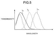
- FIG. 5 is a view illustrating an example of a characteristic of each filter of the color filter 202a_1 according to this embodiment, the view illustrating relationship between a wavelength of the light and transmissivity of each filter.
- a transmissivity curve is standardized such that maximum values of the transmissivity of respective filters are the same.
- a curve L b (solid line), a curve Lg (broken line), and a curve L m (dashed line) illustrated in FIG. 5 indicate the transmissivity curves of the B filter, the G filter, and the Mg filter, respectively.
- the B filter transmits the light of the wavelength band H B .
- the Mg filter transmits the light of a wavelength band of magenta being a complementary color of green.
- the Mg filter absorbs the light of the wavelength band H G and transmits the light of the wavelength bands H B and H R .
- the G filter transmits the light of the wavelength band H G .
- the complementary color refers to the color formed of the light including at least two wavelength bands out of the wavelength bands H B , H G , and H R .
- FIG. 6 is a schematic diagram illustrating another example of the configuration (configuration 2) of the color filter 202a according to this embodiment.
- a color filter 202a_2 illustrated in FIG. 6 is such that filter units U2 each of which is formed of four filters arranged in a 2 ⁇ 2 lattice pattern, for example, are arranged in a two-dimensional manner in this embodiment.
- the filter unit U2 is formed of one B filter which transmits the light of the wavelength band H B , two Cy filters which transmit the light of the wavelength bands H B and H G , and one R filter which transmits the light of the wavelength band H R .
- the Cy filter transmits the light of a wavelength band of cyan being a complementary color of red.
- the Cy filter absorbs the light of the wavelength band H R and transmits the light of the wavelength bands H B and H G .
- the filter unit U2 includes two filters which transmit the light of the wavelength band H G (Cy filters) and three filters which transmit the light of the wavelength band H B (B filter and Cy filters).
- FIG. 7 is a schematic diagram illustrating another example of the configuration (configuration 3) of the color filter 202a according to this embodiment.
- a color filter 202a_3 illustrated in FIG. 7 is such that filter units U3 each of which is formed of four filters arranged in a 2 ⁇ 2 lattice pattern, for example, are arranged in a two-dimensional manner in this embodiment.
- the filter unit U3 is formed of one B filter which transmits the light of the wavelength band H B , two Cy filters which transmit the light of the wavelength bands H B and H G , and one Mg filter which transmits the light of the wavelength bands H B and H R .
- the filter unit U3 includes two filters which transmit the light of the wavelength band H G (Cy filters) and four filters which transmit the light of the wavelength band H B (B filter, Cy filters, and Mg filter).
- FIG. 8 is a schematic diagram illustrating another example of the configuration (configuration 4) of the color filter 202a according to this embodiment.
- a color filter 202a_4 illustrated in FIG. 8 is such that filter units U4 each of which is formed of four filters arranged in a 2 ⁇ 2 lattice pattern, for example, are arranged in a two-dimensional manner in this embodiment.
- the filter unit U4 is formed of one B filter which transmits the light of the wavelength band H B , two Cy filters which transmit the light of the wavelength bands H B and H G , and one W filter which transmits the light of the wavelength bands H B , H G , and H R .
- the W filter transmits the light of a white wavelength band.
- the W filter transmits the light of the wavelength bands H B , H G , and H R (white light). Meanwhile, it is also possible not to provide the W filter but make this region a vacant (transparent) filter region.
- the filter unit U4 includes three filters which transmit the light of the wavelength band H G (Cy filters and W filter) and four filters which transmit the light of the wavelength band H B (B filter, Cy filters, and W filter).
- FIG. 9 is a schematic diagram illustrating another example of the configuration (configuration 5) of the color filter 202a according to this embodiment.
- a color filter 202a_5 illustrated in FIG. 9 is such that filter units U5 each of which is formed of 16 filters arranged in a 4 ⁇ 4 matrix pattern, for example, are arranged in a two-dimensional manner in this embodiment.
- the filter unit U5 includes a plurality of the above-described B filters, G filters, and Mg filters in which the G filters are arranged on an orthogonal line.
- the filter unit U5 includes eight filters which transmit the light of the wavelength band H G (G filters) and eight filters which transmit the light of the wavelength band H B (B filters and Mg filters).
- FIG. 10 is a schematic diagram illustrating another example of the configuration (configuration 6) of the color filter according to this embodiment.
- a color filter 202a_6 illustrated in FIG. 10 is such that filter units U6 each of which is formed of 16 filters arranged in a 4 ⁇ 4 lattice pattern, for example, are arranged in a two-dimensional manner in this embodiment.
- the filter unit U6 includes a plurality of the above-described B filters, Mg filters, and W filters in which the W filters are arranged on an orthogonal line.
- the filter unit U6 includes eight filters which transmit the light of the wavelength band H G (W filters) and 16 filters which transmit the light of the wavelength band H B (B filters, Mg filters, and W filters).
- any one of the above-described six types of color filters 202a is provided on the light receiving surface of the imaging device 202 in this embodiment.
- Any color filter in which the number of filters which transmit the light of the wavelength band H G is equal to or larger than half the number of filters which form the filter unit and the number of filters which transmit the light of the wavelength band H B is equal to or larger than the number of filters which transmit the light of the wavelength band H G in the filter unit may serve as the color filter 202a according to the above-described embodiment; arrangement satisfying the above-described condition is also applicable in addition to the above-described arrangement.
- the pixel P ij which receives the light of the wavelength band H G the pixel P ij which receives the light of the wavelength band H R
- the pixel P ij which receives the light of the wavelength bands H B and H G the pixel P ij which receives the light of the wavelength band H B and H R
- the pixel P ij which receives the light of the wavelength bands H B , H G , and H R are described as the G pixel, the R pixel, the Cy pixel, the Mg pixel, and the W pixel, respectively.
- the light guide 203 formed of a glass fiber and the like serves as a light guide path of the light emitted from the light source unit 3.
- the lens for illumination 204 provided at a distal end of the light guide 203 diffuses the light guided by the light guide 203 to emit from the distal end 24 to outside.
- the A/D converter 205 A/D converts the image signal generated by the imaging device 202 and outputs digital-converted image signal (electric signal) to the processor unit 4.
- the imaging information recording unit 206 stores data including various programs for operating the endoscope 2, various parameters required for operating the endoscope 2, identification information D of the endoscope 2 and the like.
- the identification information D includes a scope ID being specific information (ID) of the endoscope 2, a model year, specification information, a transmission system, a transmission rate, arrangement information of the transmission filters regarding the color filter 202a associated with the scope ID and the like.
- the imaging information recording unit 206 is realized by using a semiconductor memory such as a flash memory.
- the light source unit 3 is provided with an illuminating unit 31 and an illumination control unit 32.
- the illuminating unit 31 switches between a plurality of types of illumination light of different wavelength bands to emit under the control of the illumination control unit 32.
- the illuminating unit 31 switches between a plurality of types of illumination light of different wavelength bands to emit.
- the illuminating unit 31 includes a light source 31a, a light source driver 31b, a switching filter 31c, a driving unit 31d, a driving driver 31e, and a condenser lens 31f.
- the light source 31a emits the white illumination light including the light of the red, green, and blue wavelength bands H B , H G , and H R under the control of the illumination control unit 32.
- the white illumination light emitted by the light source 31a is emitted from the distal end 24 to outside through the switching filter 31c, the condenser lens 31f, and the light guide 203.
- the light source 31a is realized by using the light source which emits the white light such as a white LED and a xenon lamp.
- the light source driver 31b supplies the light source 31a with current to allow the light source 31a to emit the white illumination light under the control of the illumination control unit 32.
- the switching filter 31c transmits only the blue narrow band light and the green narrow band light out of the white illumination light emitted by the light source 31a.
- the switching filter 31c is removably put on an optical path of the white illumination light emitted by the light source 31a under the control of the illumination control unit 32.
- the switching filter 31c is put on the optical path of the white illumination light to transmit only the two types of narrow band light. Specifically, the switching filter 31c transmits the narrow band illumination light formed of light of a narrow band T B included in the wavelength band H B (for example, 390 nm to 445 nm) and light of a narrow band T G included in the wavelength band H G (for example, 530 nm to 550 nm).
- the narrow bands T B and T G are the wavelength bands of blue light and green light easily absorbed by hemoglobin in blood.
- Light limited to the band to be emitted is referred to as the narrow band illumination light and observation of the image by using the narrow band illumination light is referred to as a narrow band imaging (NBI) system.
- NBI narrow band imaging
- the driving unit 31d puts/removes the switching filter 31c on/from the optical path of the light source 31a.
- the driving unit 31d is formed of a stepping motor, a DC motor and the like.
- the driving driver 31e supplies the driving unit 31d with predetermined current under the control of the illumination control unit 32.
- the condenser lens 31f condenses the white illumination light emitted by the light source 31a or the narrow band illumination light transmitted through the switching filter 31c to emit out of the light source unit 3 (light guide 203).
- the illumination control unit 32 controls the light source driver 31b to turn on/off the light source 31a.
- the illumination control unit 32 controls the type (band) of the illumination light emitted by the illuminating unit 31 by putting/removing the switching filter 31c on/from the optical path of the light source 31a by controlling the driving driver 31e.
- the illumination control unit 32 controls to switch the illumination light emitted by the illuminating unit 31 to the white illumination light or the narrow band illumination light by putting/removing the switching filter 31c on/from the optical path of the light source 31a.
- the illumination control unit 32 controls to switch to a white light imaging (WLI) system in which the white illumination light including the light of the wavelength bands H B , H G , and H R is used or the narrow band imaging (NBI) system in which the narrow band illumination light formed of the light of the narrow bands T B and T G is used.
- WLI white light imaging
- NBI narrow band imaging
- the processor unit 4 is provided with a noise reducing unit 41, a frame memory 42, an image processing unit 43, a display image generating unit 44, a recording unit 45, an input unit 46, and a control unit 47.
- the noise reducing unit 41 performs NR processing of reducing a noise component included in the image signal input from the A/D converter 205 to output to the image processing unit 43 and the frame memory 42.
- the noise reducing unit 41 includes a motion compensating unit 411 and a pixel adding unit 412.
- the motion compensating unit 411 selects a pixel of interest based on used filter information determined according to the light emitted by the light source unit 3 and the characteristic of each filter forming the color filter 202a recorded in a used filter information recording unit 451 to be described later and detects motion between the images which the imaging device 202 captures at different times to generate by using the electric signal (pixel value) output by the pixel of interest, thereby reducing the noise component included in the image signal generated by the imaging device 202. Specifically, the motion compensating unit 411 performs motion compensating processing of compensating motion between two images (frames) corresponding to the image signals temporally adjacent to each other generated by the imaging device 202.
- the pixel adding unit 412 adds the pixel value of each pixel of a previous frame (compensated image) corresponding to the image signal on which the motion compensation of the image is performed input from the motion compensating unit 411 to the pixel value (electric signal) of each pixel of a current frame (latest frame) corresponding to a latest image signal input from the A/D converter 205 or takes an average of them, thereby reducing the noise component included in the current frame (latest image) corresponding to the image signal of the latest image and outputs the current frame (latest image) corresponding to the image signal from which the noise component is reduced to the frame memory 42 and the image processing unit 43.
- the frame memory 42 stores the image signal (current frame) from which the noise component is reduced input from the noise reducing unit 41.
- the frame memory 42 is formed of a semiconductor memory such as an SDRAM.
- the image processing unit 43 performs various types of image processing on the current frame (latest image) corresponding to the latest image signal input from the noise reducing unit 41 to output to the display image generating unit 44.
- the image processing performed by the image processing unit 43 includes OB clamping processing of correcting an offset amount of a black level, demosaicing processing of interpolating a lacking color component based on a correlation value of color information of a plurality of pixels, and gain adjusting processing of performing gradation processing of a brightness level and color image generating processing of generating a color image signal of the image signal on which the demosaicing processing is applied.
- the display image generating unit 44 performs gradation converting processing, enlarging processing and/or structure emphasis processing of a capillary, a mucosal fine pattern or the like on a mucous membrane surface on the current frame (latest image) corresponding to the image signal of the latest image input from the image processing unit 43 to output to the display unit 5.
- the recording unit 45 records data including various programs for operating the endoscope device 1, various parameters required for operating the endoscope device 1 and the like.
- the recording unit 45 is realized by using a semiconductor memory such as a flash memory and an SDRAM.
- the recording unit 45 includes the used filter information recording unit 451.
- the used filter information recording unit 451 records the used filter information regarding the filter used when the motion compensating unit 411 performs the motion compensation on the image signal generated by the imaging device 202.
- FIG. 11 is a view illustrating an example of the used filter information which the used filter information recording unit 451g records.
- Used filter information T1 illustrated in FIG. 11 records the type of filter used by the motion compensating unit 411 in the motion compensating processing according to the type of illumination light for each color filter.
- the color filter 202a provided on the imaging device 202 is basically fixed and may not be changed, the endoscope 2 (scope) itself may be changed in this embodiment. Therefore, "type of color filter” is associated with “used filter information T1" illustrated in FIG. 11 to be managed as the "scope ID" in actual usage; however, this is represented herein as "color filter type” for making the description simple. Under this precondition, conditions when the motion compensating unit 411 sets the filter used in the motion compensating processing is described.
- the motion compensating unit 411 sets the filter used in the motion compensating processing, this first sets the filter based on condition 1 out of following two conditions 1 and 2, and when there is a plurality of candidates with condition 1, this narrows the candidates to set the used filter based on condition 2:
- the color filter 202a_1 is described.
- the G filter serves as the filter for the motion compensating processing based on condition 1.
- the Mg filter transmits only the light of the wavelength band H B , so that this is substantially regarded as the B filter. Therefore, based on condition 1, the number of filters which transmit the light of the wavelength band H B and the number of filters which transmit the light of the wavelength band H G are the same. Then, condition 2 is applied and the B filter (including the Mg filter) serves as the filter for the motion compensating processing because the B filter has higher sensitivity than the G filter.
- the color filter 202a_2 is described.
- the Cy filter serves as the filter for the motion compensating processing based on condition 1.
- the illumination light is the narrow band light, since the Cy filter directly transmits a cyan color component, so that the Cy filter serves as the filter for the motion compensating processing based on condition 1 in this case also.
- the color filter 202a_3 is described.
- the Cy filter serves as the filter for the motion compensating processing based on condition 1.
- the Mg filter transmits only the light of the wavelength band H B , so that this is substantially regarded as the B filter. Therefore, based on condition 1, the number of filters which transmit only the light of the wavelength band H B and the number of filters which transmit the cyan color component are the same. Then, condition 2 is applied and the Cy filter serves as the filter for the motion compensating processing when the illumination light is the narrow band light because the Cy filter has higher sensitivity than the B filter.
- the color filter 202a_4 is described.
- the Cy filter serves as the filter for the motion compensating processing based on condition 1.
- the W filter transmits the light of the wavelength band H B and the light of the wavelength band H G , so that this is substantially regarded as the Cy filter. Therefore, the Cy filter (including the W filter) serves as the filter for the motion compensating processing also when the illumination light is the narrow band light.
- the color filter 202a_5 is described.
- the G filter serves as the filter for the motion compensating processing based on condition 1.
- the Mg filter transmits only the light of the wavelength band H B , so that this is substantially regarded as the B filter. Therefore, based on condition 1, the number of substantial B filters and the number of G filters are the same. Then, condition 2 is applied and the B filter (including the Mg filter) serves as the filter for the motion compensating processing because the B filter has higher sensitivity than the G filter.
- the color filter 202a_6 is described.
- the W filter serves as the filter for the motion compensating processing based on condition 1.
- the W filter is substantially regarded as the Cy filter and the Mg filter is substantially regarded as the B filter. Therefore, based on condition 1, the number of filters which transmit the cyan color component and the number of filter which transmit only the light of the wavelength band H B are the same. Then, condition 2 is applied and the W filter which is substantially the Cy filter serves as the filter for the motion compensating processing because the Cy filter has higher sensitivity than the B filter.
- the motion compensating unit 411 specifies the filter which should be used in the motion compensating processing with reference to the type information of the illumination light and the used filter information T1 (scope ID) and performs the motion compensating processing of the images captured at different times by using the electric signal output by the pixel (pixel of interest) corresponding to the specified filter.
- the input unit 46 being an interface for inputting to the endoscope device 1 by the user includes a power switch for turning on/off the power, a mode switching button for switching a shooting mode and various other modes, an illumination light switching button for switching the illumination light of the light source unit 3 and the like.
- the control unit 47 controls driving of each component including the endoscope 2 and the light source unit 3 and controls input/output of information to/from each component.
- the control unit 47 outputs setting data for imaging control stored in the recording unit 45 (for example, the pixel to be read), a timing signal indicating imaging timing, an emitting timing signal indicating an emitting timing by the light source unit 3 and the like to the endoscope 2 and the light source unit 3 through a predetermined signal line and bus.
- the control unit 47 outputs the type information of the illumination light and the color filter information (identification information D) obtained through the imaging information recording unit 206 to the noise reducing unit 41.
- the display unit 5 displays an image corresponding to a display image signal input from the processor unit 4.
- the display unit 5 is formed of a liquid crystal, organic EL (electro luminescence) or the like.
- FIG. 12 is a flowchart illustrating an overview of the process executed by the endoscope device 1. Meanwhile, an example of the color filter 202a_1 (filter unit U1) is described in the following process.
- the control unit 47 first obtains the color filter information (scope ID) from an identification information recording unit 206a of the imaging information recording unit 206 of the endoscope 2 connected to the processor unit 4 (step S101). In this case, the control unit 47 outputs the color filter information obtained from the identification information recording unit 206a to the motion compensating unit 411.
- step S102 when the imaging system of the endoscope device 1 is the white illumination light imaging system (step S102: Yes), if the switching filter 31c is put on the optical path of the white light emitted by the light source 31a (step S103: Yes), the illumination control unit 32 retracts the switching filter 31c from the optical path of the light source 31a by controlling the driving unit 31d (step S104).
- the illumination control unit 32 allows the light source 31a to emit the white light toward biological tissue in the subject (step S105).
- the illumination control unit 32 allows the light source 31a to continuously emit the white light until an instruction signal to give an instruction to finish examining the subject or the instruction signal to give an instruction to emit the narrow band illumination light is input from the operating unit 22.
- the illumination control unit 32 outputs the type information of the illumination light to the motion compensating unit 411 through the control unit 47.
- control unit 47 allows the imaging device 202 to image the biological tissue in the subject on which the light source unit 3 emits the white light (step S106).
- the motion compensating unit 411 obtains the current frame corresponding to the image signal of the latest image generated by the imaging device 202 through the A/D converter 205, the previous frame corresponding to a previous image signal from which the noise component is reduced from the frame memory 42, and the used filter information from the used filter information recording unit 451 (step S107).
- the motion compensating unit 411 executes the motion compensating processing to compensate the motion between the previous frame and the current frame based on the color filter information, the type information of the illumination light, and the used filter information input from the control unit 47 (step S108).
- FIG. 13 is a view schematically illustrating a method of selecting the pixel used in the motion compensating processing executed by the motion compensating unit 411 on the previous frame and the current frame.
- the motion compensating unit 411 performs the motion compensating processing to compensate the motion between a previous frame F1 and a current frame F2 by using a block matching method on the previous frame F1 corresponding to the previous image signal.
- the block matching method detects a position in the current frame F2 to which a target pixel M1' of the previous frame F1 moves, for example.
- the motion compensating unit 411 makes a block B1 (small region) around the target pixel M1' a template and scans the current frame F2 by using the template of the block B1 around a pixel f 2 in the same position as the position of the target pixel M1' of the previous frame F1 in the current frame F2 to make a central pixel in a position in which a difference absolute value sum between the templates is the smallest a target pixel M1. That is to say, the motion compensating unit 411 detects a motion amount Y1 (motion vector) from the target pixel M1' to the target pixel M1 in the current frame F2 and performs the process on all the pixels of the previous frame F1.
- a motion amount Y1 motion vector
- the motion compensating unit 411 selects the pixel of interest based on the color filter information, the type information of the illumination light, and the used filter information. Specifically, as illustrated in FIG. 14 , when the color filter 202a is the color filter 202a_1 (filter unit U1) and the illumination light is the white light, if the target pixel M1 is the pixel of interest and a pixel P 43 , the motion compensating unit 411 scans the previous frame F1 for the pixel of interest by using the block B1 formed of the pixels adjacent to the pixel P 43 around the pixel P 43 the template according to the used filter information. Meanwhile, in FIG. 14 , the filter corresponding to the pixel ij is described in parentheses.
- the motion compensating unit 411 scans the previous frame F1 by using the block B1 formed of pixels P 23 , P 32 , P 34 , and P 43 around the pixel P 33 being the pixels of interest in place of the pixel P 33 as the template according to the used filter information. According to this, the motion compensation according to a characteristic of the illumination light may be performed, so that the motion amount Y1 generated between the previous frame F1 and the current frame F2 may be correctly detected.
- step S109 are continuously described.
- the pixel adding unit 412 performs pixel adding processing to add the pixel value of each pixel of the current frame (latest image) corresponding to the latest image signal on which the motion compensating unit 411 performs the motion compensation to the pixel value of each pixel of the current frame (latest image) corresponding to the latest image signal or takes an average of them to output to the image processing unit 43.
- the image processing unit 43 performs the image processing of performing the demosaicing processing, color component generating processing, the color image generating processing and the like on the image signal input from the noise reducing unit 41 to output to the display image generating unit 44 (step S110).
- the display image generating unit 44 performs display image generating processing of generating the display image signal for display on the image signal input from the image processing unit 43 to output to the display unit 5 (step S111).
- the endoscope device 1 shifts to step S121 to be described later.
- step S103 when the switching filter 31c is not put on the optical path of the white light emitted by the light source 31a (step S103: No), the endoscope device 1 shifts to step S105.
- the imaging system of the endoscope device 1 is not the white illumination light imaging system, that is to say, the narrow band imaging at step S102 (step S102: No) is described.
- the illumination control unit 32 allows the illuminating unit 31 to emit the narrow band light to the biological tissue in the subject (step S114).
- the illumination control unit 32 allows the light source 31a to continuously emit the white light until the instruction signal to give an instruction to finish examining the subject or the instruction signal to give an instruction to emit the narrow band illumination light is input from the operating unit 22.
- the illumination control unit 32 outputs the type information of the illumination light to the motion compensating unit 411 through the control unit 47.
- control unit 47 allows the imaging device 202 to image the biological tissue in the subject irradiated with the narrow band light emitted by the illuminating unit 31 (step S115).
- the motion compensating unit 411 obtains the current frame corresponding to the latest image signal generated by the imaging device 202 through the A/D converter 205, the previous frame corresponding to the previous image signal from which the noise component is reduced from the frame memory 42, and the used filter information from the used filter information recording unit 451 (step S116).
- the motion compensating unit 411 executes the motion compensating processing to compensate the motion between the previous image signal and the latest image signal based on the used filter information obtained from the used filter information recording unit 451 (step S117).
- the pixel adding unit 412 performs the pixel adding processing to add the pixel value of each pixel of the current frame corresponding to the latest image signal on which the motion compensating unit 411 performs the motion compensation to the pixel value of each pixel of the current frame corresponding to the latest image signal to output to the image processing unit 43 (step S118).
- the image processing unit 43 performs the image processing of performing the demosaicing processing, the color component generating processing, the color image generating processing and the like on the image signal input from the noise reducing unit 41 to output to the display image generating unit 44 (step S119).
- the display image generating unit 44 performs the display image generating processing of allocating the pixel value of the B pixel and a component of the capillary input from the image processing unit 43 to a B channel and a G channel of the display unit 5 and allocating a component of a deep blood vessel to an R channel to output to the display unit 5 (step S120).
- a site of the capillary on a surface is colored to reddish-blown and other sites are colored to cyan to green and an emphasized image in which the capillary on the mucous membrane surface is emphasized is displayed on the display unit 5.
- the endoscope device 1 shifts to step S121.
- step S111 or step S120 when the instruction signal to finish examining the subject is input through the operating unit 22 (step S121: Yes), the endoscope device 1 finishes this process. In this case, the illumination control unit 32 stops the light source 31a. On the other hand, when the instruction signal to finish examining the subject is not input through the operating unit 22 (step S121: No), the endoscope device 1 returns to step S102.
- step S112 When the switching filter 31c is not put on the optical path of the white light emitted by the light source 31a at step S112 (step S112: No), the illumination control unit 32 controls the driving unit 31d to put the switching filter 31c on the optical path of the light source 31a (step S113). After step S113, the endoscope device 1 shifts to step S114.
- the endoscope device 1 is described to switch the illumination light emitted by the illuminating unit 31 between the white illumination light and the narrow band illumination light by putting/removing the switching filter 31c regarding the white light emitted from one light source 31a, it is also possible to switch two light sources which emit the white illumination light and the narrow band illumination light to emit any one of the white illumination light and the narrow band illumination light.
- the two light sources are switched to emit any one of the white illumination light and the narrow band illumination light, it is also possible to apply to a capsule endoscope introduced into the subject provided with the light source unit, the color filter, and the imaging device, for example.
- any color filter in which the number of filters which transmit the light of the wavelength band H G is equal to or larger than half the number of filters which form the filter unit and the number of filters which transmit the light of the wavelength band H B is equal to or larger than the number of filters which transmit the light of the wavelength band H G in the filter unit may serve as the color filter according to the present invention; arrangement satisfying the above-described condition is also applicable in addition to the above-described arrangement.
- each transmitting filter may also be individually provided on each pixel of the imaging device.
- the endoscope device may also be applied to an ultrasound endoscope in which the imaging device and an ultrasound transducer are embedded in the distal end thereof and the capsule endoscope which may be introduced into the subject.
- the capsule endoscope if the two light sources are switched to emit any one of the white illumination light and the narrow band illumination light, the light source unit, the color filter, and the imaging device may be provided in a casing of the capsule, for example.
Landscapes
- Health & Medical Sciences (AREA)
- Life Sciences & Earth Sciences (AREA)
- Engineering & Computer Science (AREA)
- Physics & Mathematics (AREA)
- Surgery (AREA)
- Optics & Photonics (AREA)
- Medical Informatics (AREA)
- Public Health (AREA)
- Nuclear Medicine, Radiotherapy & Molecular Imaging (AREA)
- Pathology (AREA)
- Radiology & Medical Imaging (AREA)
- General Health & Medical Sciences (AREA)
- Biomedical Technology (AREA)
- Heart & Thoracic Surgery (AREA)
- Veterinary Medicine (AREA)
- Biophysics (AREA)
- Animal Behavior & Ethology (AREA)
- Molecular Biology (AREA)
- Signal Processing (AREA)
- Multimedia (AREA)
- General Physics & Mathematics (AREA)
- Spectroscopy & Molecular Physics (AREA)
- Astronomy & Astrophysics (AREA)
- Theoretical Computer Science (AREA)
- Endoscopes (AREA)
- Instruments For Viewing The Inside Of Hollow Bodies (AREA)
- Closed-Circuit Television Systems (AREA)
Abstract
Description
- The present invention relates to an endoscope device introduced into a living body to obtain an in-vivo image.
- Technology of detecting a motion amount between frames based on a current frame and a previous frame corresponding to image signals temporally adjacent to each other generated by an imaging device to reduce a noise component of the current frame according to the motion amount is conventionally known as noise reduction processing (hereinafter, referred to as "NR processing)) of reducing the noise component included in the image signal generated by the imaging device such as a CCD (charge coupled device) and a CMOS (complementary metal oxide semiconductor) (see Patent Literature 1).
- Technology of detecting the motion amount between the frames based on a pixel value of a pixel which receives light transmitted through a filter which transmits a specific color component out of the image signal generated by the imaging device to reduce the noise component of the current frame according to the motion amount is known as another NR processing (see Patent Literature 2).
-
- Patent Literature 1: Japanese Patent Application Laid-open No.
2005-150903 - Patent Literature 2: Japanese Patent Application Laid-open No.
2011-029722 - Recently, the endoscope device uses a narrow band imaging (NBI) system in which illumination light formed of two types of narrow band light included in blue and green light wavelength bands (hereinafter, referred to as "narrow band illumination light") is used for observing a capillary, a mucosal fine pattern and the like on a mucous membrane surface of the living body in addition to white light imaging (WLI) system in which white illumination light (hereinafter referred to as "white illumination light") is used.
- However, when the above-described white illumination light imaging system and narrow band imaging system are performed, when the NR processing is performed based on the pixel value output from the pixel on which a specific filter is provided, the pixel value of each pixel differs depending on different characteristics of the imaging system, so that there is a problem that the noise component may be appropriately reduced in one imaging system but the noise component may not be appropriately reduced in the other imaging system.
- The present invention is achieved in view of the above, and an object thereof is to provide the endoscope device capable of appropriately reducing the noise component in both the white illumination light imaging system and the narrow band imaging system.
- To solve the above-described problem and achieve the object, an endoscope device according to the present invention includes: a light source unit configured to emit white illumination light including light of red, green and blue wavelength bands or narrow band illumination light formed of narrow band light included in each of the blue and green wavelength bands; an imaging device configured to perform photoelectric conversion on light received by a plurality of pixels arranged in a lattice pattern to generate an electric signal as an image signal; a color filter in which a filter unit is arranged so as to correspond to the plurality of pixels, the filter unit formed of a plurality of filters including at least a filter which transmits the light of the blue wavelength band and a filter which transmits the light of the blue wavelength band and the light of at least one of the green and red wavelength bands in which the number of filters which transmit the light of the green wavelength band is equal to or larger than half the total number of filters of the filter unit and the number of filters which transmit the light of the blue wavelength band is equal to or larger than the number of filters which transmit the light of the green wavelength band; and a noise reducing unit configured to select a pixel of interest based on used filter information determined according to the light emitted by the light source unit and a characteristic of each filter forming the color filter and detect motion between images captured at different times by using the electric signal output by the pixel of interest, thereby reducing a noise component included in the image signal.
- The endoscope device according to the present invention has an effect of appropriately reducing the noise component in both the white illumination light imaging system and the narrow band imaging system.
-
-
FIG. 1 is a view illustrating a schematic configuration of an endoscope device according to one embodiment of the present invention. -
FIG. 2 is a schematic diagram illustrating the schematic configuration of the endoscope device according to one embodiment of the present invention. -
FIG. 3 is a schematic diagram illustrating a configuration of a pixel of an imaging device of the endoscope device according to one embodiment of the present invention. -
FIG. 4 is a schematic diagram illustrating an example of a configuration of a color filter of the endoscope device according to one embodiment of the present invention. -
FIG. 5 is a view illustrating an example of a characteristic of each filter of the color filter according to one embodiment of the present invention. -
FIG. 6 is a schematic diagram illustrating another example of the configuration of the color filter according to one embodiment of the present invention. -
FIG. 7 is a schematic diagram illustrating another example of the configuration of the color filter according to one embodiment of the present invention. -
FIG. 8 is a schematic diagram illustrating another example of the configuration of the color filter according to one embodiment of the present invention. -
FIG. 9 is a schematic diagram illustrating another example of the configuration of the color filter according to one embodiment of the present invention. -
FIG. 10 is a schematic diagram illustrating another example of the configuration of the color filter according to one embodiment of the present invention. -
FIG. 11 is a view illustrating an example of used filter information recorded by a used filter information recording unit of the endoscope device according to one embodiment of the present invention. -
FIG. 12 is a flowchart illustrating an overview of a process executed by the endoscope device according to one embodiment of the present invention. -
FIG. 13 is a view schematically illustrating motion compensation between images at different imaging timings performed by a motion compensating unit according to one embodiment of the present invention. -
FIG. 14 is a view schematically illustrating a pixel of interest and a block used in motion compensating processing performed by the motion compensating unit according to one embodiment of the present invention. -
FIG. 15 is a view schematically illustrating another pixel of interest and another block used in the motion compensating processing performed by the motion compensating unit according to one embodiment of the present invention. - A mode for carrying out the present invention (hereinafter, referred to as an "embodiment") is hereinafter described. A medical endoscope device which captures an image in a body cavity of a subject such as a patient to display is described in the embodiment. The present invention is not limited by the embodiment. In the drawings, the same part is described with the same reference numeral assigned.
-
FIG. 1 is a view illustrating a schematic configuration of the endoscope device according to one embodiment of the present invention.FIG. 2 is a schematic diagram illustrating the schematic configuration of the endoscope device according to one embodiment of the present invention. - An
endoscope device 1 illustrated inFIGS. 1 and2 is provided with an endoscope 2 (endoscope) which image an observed region in the subject with a distal end inserted in the body cavity of the subject, thereby generating an in-vivo image (image signal) of the observed region, a light source unit 3 (light source device) which emits white illumination light including light of red, green, and blue wavelength bands or narrow band illumination light formed of narrow band light included in each of the above-described blue and green wavelength bands from the distal end of theendoscope 2 toward the observed region through theendoscope 2, a processor unit 4 (processing device) which applies predetermined imaging processing on the in-vivo image generated by animaging device 202 and generally controls operation of anentire endoscope device 1, and adisplay unit 5 which displays the in-vivo image on which theprocessor unit 4 applies the image processing. Theendoscope device 1 obtains the in-vivo image in the body cavity with aninsertion part 21 inserted in the body cavity of the subject such as the patient. A user such as a doctor observes the obtained in-vivo image to examine whether there is a bleeding site and a tumor site (lesion S) being sites to be detected. - A configuration of the
endoscope 2 is first described. - The
endoscope 2 is provided with aflexible insertion part 21 having an elongated shape, anoperating unit 22 connected to a proximal end side of theinsertion part 21 to accept an input of various operating signals, and auniversal code 23 extending in a direction different from a direction in which theinsertion part 21 extends from theoperating unit 22 in which various cables connected to thelight source unit 3 and theprocessor unit 4 are embedded. - The
insertion part 21 includes adistal end 24 in which theimaging device 202 including pixels (photo diodes) which receive light arranged in a lattice (matrix) pattern which generates the image signal by performing photoelectric conversion on the light received by the pixels is embedded, abending part 25 freely bendable formed of a plurality of bending pieces, and an elongatedflexible tube part 26 having flexibility connected to a proximal end side of thebending part 25. - The
operating unit 22 includes abending knob 221 which bends the bendingpart 25 upward/downward and rightward/leftward and a plurality ofswitches 222 being an operation input unit which inputs operation instruction signals of peripheral devices such as air supply means, water supply means, and gas supply means in addition to thelight source unit 3 and the processor unit 4 (seeFIG. 1 ). Theoperating unit 22 also includes a treatmenttool insertion part 223 from which a treatment tool such as in-vivo forceps, a laser scalpel, and an inspection probe is inserted in the body cavity; the treatment tool inserted from the treatmenttool insertion part 223 is exposed from an aperture (not illustrated) through a treatment tool channel (not illustrated) of thedistal end 24. - The
universal code 23 includes at least alight guide 203 and a condenser cable formed of one cable of a plurality of assembled cables embedded therein. The cable assembly being a signal line which transmits and receives a signal between theendoscope 2 and thelight source unit 3 andprocessor unit 4 includes a signal line for transmitting and receiving setting data, a signal line for transmitting and receiving the image signal, a signal line for transmitting and receiving a driving timing signal for driving theimaging device 202 and the like. Theuniversal code 23 includes aconnector unit 27 detachably attached to thelight source unit 3. Theconnector unit 27 from which a coil-shaped coil cable 27a extends includes aconnector unit 28 detachably attached to theprocessor unit 4 on an extended end of thecoil cable 27a. - The
endoscope 2 is at least provided with an imagingoptical system 201, theimaging device 202, thelight guide 203, a lens forillumination 204, an A/D converter 205, and an imaginginformation recording unit 206. - The imaging
optical system 201 provided at the distal end of theendoscope 2 condenses at least the light from the observed region. The imagingoptical system 201 is formed of one or a plurality of lenses. Meanwhile, the imagingoptical system 201 may also be provided with an optical zooming mechanism which changes an angle of view and a focusing mechanism which changes a focal point. - The
imaging device 202 provided so as to be perpendicular to an optical axis of the imagingoptical system 201 performs the photoelectric conversion on an image of the light formed by the imagingoptical system 201 to generate an electric signal (image signal). Theimaging device 202 is realized by using a CCD (charge coupled device) image sensor and a CMOS (complementary metal oxide semiconductor) image sensor. - Here, a configuration of the pixel of the
imaging device 202 is described.FIG. 3 is a schematic diagram illustrating the configuration of the pixel of theimaging device 202. - As illustrated in
FIG. 3 , theimaging device 202 includes a plurality of pixels which receives the light from the imagingoptical system 201 arranged in a lattice (matrix) pattern. Theimaging device 202 performs the photoelectric conversion on the light received by each pixel to generate the electric signal (also referred to as the image signal, a pixel value and the like) as the image signal. The electric signal includes the pixel value (luminance value), positional information of the pixel and the like. InFIG. 3 , the pixel arranged on i-th row j-th column is represented as a pixel Pij. - The
imaging device 202 is provided with acolor filter 202a including a plurality of filters each of which transmits the light of an individually set wavelength band arranged between the imagingoptical system 201 and theimaging device 202. Thecolor filter 202a is provided on a light receiving surface of theimaging device 202. - Here, a configuration of the
color filter 202a is described. In this embodiment, a plurality of types ofcolor filters 202a may be used. Therefore, the configuration of thecolor filter 202a applicable to this embodiment is hereinafter described. -
FIG. 4 is a schematic diagram illustrating an example of the configuration (configuration 1) of thecolor filter 202a. - A color filter 202a_1 illustrated in
FIG. 4 is such that filter units U1 each of which is formed of four filters arranged in a 2 × 2 matrix pattern, for example, are arranged in a two-dimensional manner (matrix pattern) according to arrangement of the pixels Pij in this embodiment. The pixel Pij on which the filter is provided receives the light of the wavelength band which the filter transmits. For example, the pixel Pij on which the filter which transmits the light of the blue wavelength band is provided receives the light of the blue wavelength band. Hereinafter, the pixel Pij which receives the light of the blue wavelength band is referred to as a B pixel. Similarly, the pixel Pij which receives the light of the green wavelength band is referred to as a G pixel, and the pixel Pij which receives the light of the red wavelength band is referred to as an R pixel. - Here, the filter unit U1 transmits the light of a blue (B) wavelength band HB, a green (G) wavelength band HG, and a red (R) wavelength band HR. In addition, in the filter unit U1, a plurality of filters is selected to be arranged such that the number of filters which transmit the light of the wavelength band HG is equal to or larger than half the total number of filters forming the filter unit U1 and the number of filters which transmit the light of the wavelength band HB is equal to or larger than the number of filters which transmit the light of the wavelength band HG. The blue, green, and red wavelength bands HB, HG, and HR are such that the wavelength band HB is 390 nm to 500 nm, the wavelength band HG is 500 nm to 600 nm, and the wavelength band HR is 600 nm to 700 nm, for example.
- As illustrated in
FIG. 4 , the filter unit U1 according to this embodiment is formed of one B filter which transmits the light of the wavelength band HB, two G filters which transmit the light of the wavelength band HG, and one Mg filter which transmits the light of the wavelength bands HB and HR. Hereinafter, when the B filter is provided in a position corresponding to the pixel Pij, the B filter is represented as Bij. Similarly, when the G filter is provided in a position corresponding to the pixel Pij, the G filter is represented as Gij, and when the Mg filter is provided in a position corresponding to the pixel Pij, the Mg filter is represented as Mgij. - The filter unit U1 includes two filters which transmit the light of the wavelength band HG (G filters) and two filters which transmit the light of the wavelength band HB (B filter and Mg filter).
-
FIG. 5 is a view illustrating an example of a characteristic of each filter of the color filter 202a_1 according to this embodiment, the view illustrating relationship between a wavelength of the light and transmissivity of each filter. InFIG. 5 , a transmissivity curve is standardized such that maximum values of the transmissivity of respective filters are the same. A curve Lb (solid line), a curve Lg (broken line), and a curve Lm (dashed line) illustrated inFIG. 5 indicate the transmissivity curves of the B filter, the G filter, and the Mg filter, respectively. - As illustrated in
FIG. 5 , the B filter transmits the light of the wavelength band HB. The Mg filter transmits the light of a wavelength band of magenta being a complementary color of green. In other words, the Mg filter absorbs the light of the wavelength band HG and transmits the light of the wavelength bands HB and HR. The G filter transmits the light of the wavelength band HG. Meanwhile, in this specification, the complementary color refers to the color formed of the light including at least two wavelength bands out of the wavelength bands HB, HG, and HR. -
FIG. 6 is a schematic diagram illustrating another example of the configuration (configuration 2) of thecolor filter 202a according to this embodiment. - A color filter 202a_2 illustrated in
FIG. 6 is such that filter units U2 each of which is formed of four filters arranged in a 2 × 2 lattice pattern, for example, are arranged in a two-dimensional manner in this embodiment. The filter unit U2 is formed of one B filter which transmits the light of the wavelength band HB, two Cy filters which transmit the light of the wavelength bands HB and HG, and one R filter which transmits the light of the wavelength band HR. - The Cy filter transmits the light of a wavelength band of cyan being a complementary color of red. In other words, the Cy filter absorbs the light of the wavelength band HR and transmits the light of the wavelength bands HB and HG.
- The filter unit U2 includes two filters which transmit the light of the wavelength band HG (Cy filters) and three filters which transmit the light of the wavelength band HB (B filter and Cy filters).
-
FIG. 7 is a schematic diagram illustrating another example of the configuration (configuration 3) of thecolor filter 202a according to this embodiment. - A color filter 202a_3 illustrated in
FIG. 7 is such that filter units U3 each of which is formed of four filters arranged in a 2 × 2 lattice pattern, for example, are arranged in a two-dimensional manner in this embodiment. The filter unit U3 is formed of one B filter which transmits the light of the wavelength band HB, two Cy filters which transmit the light of the wavelength bands HB and HG, and one Mg filter which transmits the light of the wavelength bands HB and HR. - The filter unit U3 includes two filters which transmit the light of the wavelength band HG (Cy filters) and four filters which transmit the light of the wavelength band HB (B filter, Cy filters, and Mg filter).
-
FIG. 8 is a schematic diagram illustrating another example of the configuration (configuration 4) of thecolor filter 202a according to this embodiment. - A color filter 202a_4 illustrated in
FIG. 8 is such that filter units U4 each of which is formed of four filters arranged in a 2 × 2 lattice pattern, for example, are arranged in a two-dimensional manner in this embodiment. The filter unit U4 is formed of one B filter which transmits the light of the wavelength band HB, two Cy filters which transmit the light of the wavelength bands HB and HG, and one W filter which transmits the light of the wavelength bands HB, HG, and HR. - The W filter transmits the light of a white wavelength band. In other words, the W filter transmits the light of the wavelength bands HB, HG, and HR (white light). Meanwhile, it is also possible not to provide the W filter but make this region a vacant (transparent) filter region.
- The filter unit U4 includes three filters which transmit the light of the wavelength band HG (Cy filters and W filter) and four filters which transmit the light of the wavelength band HB (B filter, Cy filters, and W filter).
-
FIG. 9 is a schematic diagram illustrating another example of the configuration (configuration 5) of thecolor filter 202a according to this embodiment. - A color filter 202a_5 illustrated in
FIG. 9 is such that filter units U5 each of which is formed of 16 filters arranged in a 4×4 matrix pattern, for example, are arranged in a two-dimensional manner in this embodiment. The filter unit U5 includes a plurality of the above-described B filters, G filters, and Mg filters in which the G filters are arranged on an orthogonal line. - The filter unit U5 includes eight filters which transmit the light of the wavelength band HG (G filters) and eight filters which transmit the light of the wavelength band HB (B filters and Mg filters).
-
FIG. 10 is a schematic diagram illustrating another example of the configuration (configuration 6) of the color filter according to this embodiment. - A color filter 202a_6 illustrated in
FIG. 10 is such that filter units U6 each of which is formed of 16 filters arranged in a 4×4 lattice pattern, for example, are arranged in a two-dimensional manner in this embodiment. The filter unit U6 includes a plurality of the above-described B filters, Mg filters, and W filters in which the W filters are arranged on an orthogonal line. - The filter unit U6 includes eight filters which transmit the light of the wavelength band HG (W filters) and 16 filters which transmit the light of the wavelength band HB (B filters, Mg filters, and W filters).
- In this manner, any one of the above-described six types of
color filters 202a is provided on the light receiving surface of theimaging device 202 in this embodiment. Any color filter in which the number of filters which transmit the light of the wavelength band HG is equal to or larger than half the number of filters which form the filter unit and the number of filters which transmit the light of the wavelength band HB is equal to or larger than the number of filters which transmit the light of the wavelength band HG in the filter unit may serve as thecolor filter 202a according to the above-described embodiment; arrangement satisfying the above-described condition is also applicable in addition to the above-described arrangement. Meanwhile, hereinafter, the pixel Pij which receives the light of the wavelength band HG, the pixel Pij which receives the light of the wavelength band HR, the pixel Pij which receives the light of the wavelength bands HB and HG, the pixel Pij which receives the light of the wavelength band HB and HR, and the pixel Pij which receives the light of the wavelength bands HB, HG, and HR are described as the G pixel, the R pixel, the Cy pixel, the Mg pixel, and the W pixel, respectively. - With reference to
FIGS. 1 and2 again, the configuration of theendoscope 2 is continuously described. - The
light guide 203 formed of a glass fiber and the like serves as a light guide path of the light emitted from thelight source unit 3. - The lens for
illumination 204 provided at a distal end of thelight guide 203 diffuses the light guided by thelight guide 203 to emit from thedistal end 24 to outside. - The A/D converter 205 A/D converts the image signal generated by the
imaging device 202 and outputs digital-converted image signal (electric signal) to theprocessor unit 4. - The imaging
information recording unit 206 stores data including various programs for operating theendoscope 2, various parameters required for operating theendoscope 2, identification information D of theendoscope 2 and the like. The identification information D includes a scope ID being specific information (ID) of theendoscope 2, a model year, specification information, a transmission system, a transmission rate, arrangement information of the transmission filters regarding thecolor filter 202a associated with the scope ID and the like. The imaginginformation recording unit 206 is realized by using a semiconductor memory such as a flash memory. - Next, a configuration of the
light source unit 3 is described. - The
light source unit 3 is provided with an illuminatingunit 31 and anillumination control unit 32. - The illuminating
unit 31 switches between a plurality of types of illumination light of different wavelength bands to emit under the control of theillumination control unit 32. The illuminatingunit 31 switches between a plurality of types of illumination light of different wavelength bands to emit. The illuminatingunit 31 includes alight source 31a, alight source driver 31b, a switchingfilter 31c, adriving unit 31d, a drivingdriver 31e, and acondenser lens 31f. - The
light source 31a emits the white illumination light including the light of the red, green, and blue wavelength bands HB, HG, and HR under the control of theillumination control unit 32. The white illumination light emitted by thelight source 31a is emitted from thedistal end 24 to outside through the switchingfilter 31c, thecondenser lens 31f, and thelight guide 203. Thelight source 31a is realized by using the light source which emits the white light such as a white LED and a xenon lamp. - The
light source driver 31b supplies thelight source 31a with current to allow thelight source 31a to emit the white illumination light under the control of theillumination control unit 32. - The switching
filter 31c transmits only the blue narrow band light and the green narrow band light out of the white illumination light emitted by thelight source 31a. The switchingfilter 31c is removably put on an optical path of the white illumination light emitted by thelight source 31a under the control of theillumination control unit 32. The switchingfilter 31c is put on the optical path of the white illumination light to transmit only the two types of narrow band light. Specifically, the switchingfilter 31c transmits the narrow band illumination light formed of light of a narrow band TB included in the wavelength band HB (for example, 390 nm to 445 nm) and light of a narrow band TG included in the wavelength band HG (for example, 530 nm to 550 nm). The narrow bands TB and TG are the wavelength bands of blue light and green light easily absorbed by hemoglobin in blood. Light limited to the band to be emitted is referred to as the narrow band illumination light and observation of the image by using the narrow band illumination light is referred to as a narrow band imaging (NBI) system. - The driving
unit 31d puts/removes the switchingfilter 31c on/from the optical path of thelight source 31a. The drivingunit 31d is formed of a stepping motor, a DC motor and the like. - The driving
driver 31e supplies thedriving unit 31d with predetermined current under the control of theillumination control unit 32. - The
condenser lens 31f condenses the white illumination light emitted by thelight source 31a or the narrow band illumination light transmitted through the switchingfilter 31c to emit out of the light source unit 3 (light guide 203). - The
illumination control unit 32 controls thelight source driver 31b to turn on/off thelight source 31a. Theillumination control unit 32 controls the type (band) of the illumination light emitted by the illuminatingunit 31 by putting/removing the switchingfilter 31c on/from the optical path of thelight source 31a by controlling the drivingdriver 31e. Specifically, theillumination control unit 32 controls to switch the illumination light emitted by the illuminatingunit 31 to the white illumination light or the narrow band illumination light by putting/removing the switchingfilter 31c on/from the optical path of thelight source 31a. In other words, theillumination control unit 32 controls to switch to a white light imaging (WLI) system in which the white illumination light including the light of the wavelength bands HB, HG, and HR is used or the narrow band imaging (NBI) system in which the narrow band illumination light formed of the light of the narrow bands TB and TG is used. - Next, a configuration of the
processor unit 4 is described. - The
processor unit 4 is provided with anoise reducing unit 41, aframe memory 42, an image processing unit 43, a displayimage generating unit 44, arecording unit 45, aninput unit 46, and acontrol unit 47. - The
noise reducing unit 41 performs NR processing of reducing a noise component included in the image signal input from the A/D converter 205 to output to the image processing unit 43 and theframe memory 42. Thenoise reducing unit 41 includes a motion compensating unit 411 and a pixel adding unit 412. - The motion compensating unit 411 selects a pixel of interest based on used filter information determined according to the light emitted by the
light source unit 3 and the characteristic of each filter forming thecolor filter 202a recorded in a used filterinformation recording unit 451 to be described later and detects motion between the images which theimaging device 202 captures at different times to generate by using the electric signal (pixel value) output by the pixel of interest, thereby reducing the noise component included in the image signal generated by theimaging device 202. Specifically, the motion compensating unit 411 performs motion compensating processing of compensating motion between two images (frames) corresponding to the image signals temporally adjacent to each other generated by theimaging device 202. - The pixel adding unit 412 adds the pixel value of each pixel of a previous frame (compensated image) corresponding to the image signal on which the motion compensation of the image is performed input from the motion compensating unit 411 to the pixel value (electric signal) of each pixel of a current frame (latest frame) corresponding to a latest image signal input from the A/
D converter 205 or takes an average of them, thereby reducing the noise component included in the current frame (latest image) corresponding to the image signal of the latest image and outputs the current frame (latest image) corresponding to the image signal from which the noise component is reduced to theframe memory 42 and the image processing unit 43. - The
frame memory 42 stores the image signal (current frame) from which the noise component is reduced input from thenoise reducing unit 41. Theframe memory 42 is formed of a semiconductor memory such as an SDRAM. - The image processing unit 43 performs various types of image processing on the current frame (latest image) corresponding to the latest image signal input from the
noise reducing unit 41 to output to the displayimage generating unit 44. Here, the image processing performed by the image processing unit 43 includes OB clamping processing of correcting an offset amount of a black level, demosaicing processing of interpolating a lacking color component based on a correlation value of color information of a plurality of pixels, and gain adjusting processing of performing gradation processing of a brightness level and color image generating processing of generating a color image signal of the image signal on which the demosaicing processing is applied. - The display
image generating unit 44 performs gradation converting processing, enlarging processing and/or structure emphasis processing of a capillary, a mucosal fine pattern or the like on a mucous membrane surface on the current frame (latest image) corresponding to the image signal of the latest image input from the image processing unit 43 to output to thedisplay unit 5. - The
recording unit 45 records data including various programs for operating theendoscope device 1, various parameters required for operating theendoscope device 1 and the like. Therecording unit 45 is realized by using a semiconductor memory such as a flash memory and an SDRAM. Therecording unit 45 includes the used filterinformation recording unit 451. - The used filter
information recording unit 451 records the used filter information regarding the filter used when the motion compensating unit 411 performs the motion compensation on the image signal generated by theimaging device 202. -
FIG. 11 is a view illustrating an example of the used filter information which the used filter information recording unit 451g records. Used filter information T1 illustrated inFIG. 11 records the type of filter used by the motion compensating unit 411 in the motion compensating processing according to the type of illumination light for each color filter. Although thecolor filter 202a provided on theimaging device 202 is basically fixed and may not be changed, the endoscope 2 (scope) itself may be changed in this embodiment. Therefore, "type of color filter" is associated with "used filter information T1" illustrated inFIG. 11 to be managed as the "scope ID" in actual usage; however, this is represented herein as "color filter type" for making the description simple. Under this precondition, conditions when the motion compensating unit 411 sets the filter used in the motion compensating processing is described. When the motion compensating unit 411 sets the filter used in the motion compensating processing, this first sets the filter based oncondition 1 out of following twoconditions condition 1, this narrows the candidates to set the used filter based on condition 2: - condition 1: filter of the greatest number of filters which transmit the same type of color component in the filter unit, and
- condition 2: when there is a plurality of
filters satisfying condition 1, the filter having higher sensitivity to the narrow band illumination light. Here, order of sensitivity is as follows: W filter > Cy filter > B filter > Mg filter > G filter. - Meanwhile, it is sufficient to consider
conditions - First, the color filter 202a_1 is described. When the illumination light is the white light, the G filter serves as the filter for the motion compensating processing based on
condition 1. When the illumination light is the narrow band light, the Mg filter transmits only the light of the wavelength band HB, so that this is substantially regarded as the B filter. Therefore, based oncondition 1, the number of filters which transmit the light of the wavelength band HB and the number of filters which transmit the light of the wavelength band HG are the same. Then,condition 2 is applied and the B filter (including the Mg filter) serves as the filter for the motion compensating processing because the B filter has higher sensitivity than the G filter. - The color filter 202a_2 is described. When the illumination light is the white light, the Cy filter serves as the filter for the motion compensating processing based on
condition 1. When the illumination light is the narrow band light, since the Cy filter directly transmits a cyan color component, so that the Cy filter serves as the filter for the motion compensating processing based oncondition 1 in this case also. - The color filter 202a_3 is described. When the illumination light is the white light, the Cy filter serves as the filter for the motion compensating processing based on
condition 1. When the illumination light is the narrow band light, the Mg filter transmits only the light of the wavelength band HB, so that this is substantially regarded as the B filter. Therefore, based oncondition 1, the number of filters which transmit only the light of the wavelength band HB and the number of filters which transmit the cyan color component are the same. Then,condition 2 is applied and the Cy filter serves as the filter for the motion compensating processing when the illumination light is the narrow band light because the Cy filter has higher sensitivity than the B filter. - The color filter 202a_4 is described. When the illumination light is the white light, the Cy filter serves as the filter for the motion compensating processing based on
condition 1. When the illumination light is the narrow band light, the W filter transmits the light of the wavelength band HB and the light of the wavelength band HG, so that this is substantially regarded as the Cy filter. Therefore, the Cy filter (including the W filter) serves as the filter for the motion compensating processing also when the illumination light is the narrow band light. - The color filter 202a_5 is described. When the illumination light is the white light, the G filter serves as the filter for the motion compensating processing based on
condition 1. When the illumination light is the narrow band light, the Mg filter transmits only the light of the wavelength band HB, so that this is substantially regarded as the B filter. Therefore, based oncondition 1, the number of substantial B filters and the number of G filters are the same. Then,condition 2 is applied and the B filter (including the Mg filter) serves as the filter for the motion compensating processing because the B filter has higher sensitivity than the G filter. - The color filter 202a_6 is described. When the illumination light is the white light, the W filter serves as the filter for the motion compensating processing based on
condition 1. When the illumination light is the narrow band light, the W filter is substantially regarded as the Cy filter and the Mg filter is substantially regarded as the B filter. Therefore, based oncondition 1, the number of filters which transmit the cyan color component and the number of filter which transmit only the light of the wavelength band HB are the same. Then,condition 2 is applied and the W filter which is substantially the Cy filter serves as the filter for the motion compensating processing because the Cy filter has higher sensitivity than the B filter. - In this manner, the motion compensating unit 411 specifies the filter which should be used in the motion compensating processing with reference to the type information of the illumination light and the used filter information T1 (scope ID) and performs the motion compensating processing of the images captured at different times by using the electric signal output by the pixel (pixel of interest) corresponding to the specified filter.
- With reference to
FIGS. 1 and2 again, the configuration of theprocessor unit 4 is continuously described. - The
input unit 46 being an interface for inputting to theendoscope device 1 by the user includes a power switch for turning on/off the power, a mode switching button for switching a shooting mode and various other modes, an illumination light switching button for switching the illumination light of thelight source unit 3 and the like. - The
control unit 47 controls driving of each component including theendoscope 2 and thelight source unit 3 and controls input/output of information to/from each component. Thecontrol unit 47 outputs setting data for imaging control stored in the recording unit 45 (for example, the pixel to be read), a timing signal indicating imaging timing, an emitting timing signal indicating an emitting timing by thelight source unit 3 and the like to theendoscope 2 and thelight source unit 3 through a predetermined signal line and bus. Thecontrol unit 47 outputs the type information of the illumination light and the color filter information (identification information D) obtained through the imaginginformation recording unit 206 to thenoise reducing unit 41. - Next, the
display unit 5 is described. - The
display unit 5 displays an image corresponding to a display image signal input from theprocessor unit 4. Thedisplay unit 5 is formed of a liquid crystal, organic EL (electro luminescence) or the like. - A process executed by the
endoscope device 1 having the above-described configuration is described.FIG. 12 is a flowchart illustrating an overview of the process executed by theendoscope device 1. Meanwhile, an example of the color filter 202a_1 (filter unit U1) is described in the following process. - As illustrated in
FIG. 12 , thecontrol unit 47 first obtains the color filter information (scope ID) from an identificationinformation recording unit 206a of the imaginginformation recording unit 206 of theendoscope 2 connected to the processor unit 4 (step S101). In this case, thecontrol unit 47 outputs the color filter information obtained from the identificationinformation recording unit 206a to the motion compensating unit 411. - Subsequently, when the imaging system of the
endoscope device 1 is the white illumination light imaging system (step S102: Yes), if the switchingfilter 31c is put on the optical path of the white light emitted by thelight source 31a (step S103: Yes), theillumination control unit 32 retracts the switchingfilter 31c from the optical path of thelight source 31a by controlling thedriving unit 31d (step S104). - Thereafter, the
illumination control unit 32 allows thelight source 31a to emit the white light toward biological tissue in the subject (step S105). In this case, theillumination control unit 32 allows thelight source 31a to continuously emit the white light until an instruction signal to give an instruction to finish examining the subject or the instruction signal to give an instruction to emit the narrow band illumination light is input from the operatingunit 22. At that time, theillumination control unit 32 outputs the type information of the illumination light to the motion compensating unit 411 through thecontrol unit 47. - Subsequently, the
control unit 47 allows theimaging device 202 to image the biological tissue in the subject on which thelight source unit 3 emits the white light (step S106). - Thereafter, the motion compensating unit 411 obtains the current frame corresponding to the image signal of the latest image generated by the
imaging device 202 through the A/D converter 205, the previous frame corresponding to a previous image signal from which the noise component is reduced from theframe memory 42, and the used filter information from the used filter information recording unit 451 (step S107). - Subsequently, the motion compensating unit 411 executes the motion compensating processing to compensate the motion between the previous frame and the current frame based on the color filter information, the type information of the illumination light, and the used filter information input from the control unit 47 (step S108).
-
FIG. 13 is a view schematically illustrating a method of selecting the pixel used in the motion compensating processing executed by the motion compensating unit 411 on the previous frame and the current frame. - As illustrated in
FIG. 13 , the motion compensating unit 411 performs the motion compensating processing to compensate the motion between a previous frame F1 and a current frame F2 by using a block matching method on the previous frame F1 corresponding to the previous image signal. The block matching method detects a position in the current frame F2 to which a target pixel M1' of the previous frame F1 moves, for example. For this purpose, the motion compensating unit 411 makes a block B1 (small region) around the target pixel M1' a template and scans the current frame F2 by using the template of the block B1 around a pixel f2 in the same position as the position of the target pixel M1' of the previous frame F1 in the current frame F2 to make a central pixel in a position in which a difference absolute value sum between the templates is the smallest a target pixel M1. That is to say, the motion compensating unit 411 detects a motion amount Y1 (motion vector) from the target pixel M1' to the target pixel M1 in the current frame F2 and performs the process on all the pixels of the previous frame F1. - Under conditions illustrated in
FIG. 13 , the motion compensating unit 411 selects the pixel of interest based on the color filter information, the type information of the illumination light, and the used filter information. Specifically, as illustrated inFIG. 14 , when thecolor filter 202a is the color filter 202a_1 (filter unit U1) and the illumination light is the white light, if the target pixel M1 is the pixel of interest and a pixel P43, the motion compensating unit 411 scans the previous frame F1 for the pixel of interest by using the block B1 formed of the pixels adjacent to the pixel P43 around the pixel P43 the template according to the used filter information. Meanwhile, inFIG. 14 , the filter corresponding to the pixel ij is described in parentheses. - In contrast, as illustrated in
FIG. 15 , when thecolor filter 202a is the color filter 202a_1 (filter unit U1) and the illumination light is the white light, if the target pixel M1 is not the pixel of interest but a pixel P33, the motion compensating unit 411 scans the previous frame F1 by using the block B1 formed of pixels P23, P32, P34, and P43 around the pixel P33 being the pixels of interest in place of the pixel P33 as the template according to the used filter information. According to this, the motion compensation according to a characteristic of the illumination light may be performed, so that the motion amount Y1 generated between the previous frame F1 and the current frame F2 may be correctly detected. - With reference to
FIG. 12 again, steps after step S109 are continuously described. - At step S109, the pixel adding unit 412 performs pixel adding processing to add the pixel value of each pixel of the current frame (latest image) corresponding to the latest image signal on which the motion compensating unit 411 performs the motion compensation to the pixel value of each pixel of the current frame (latest image) corresponding to the latest image signal or takes an average of them to output to the image processing unit 43.
- Subsequently, the image processing unit 43 performs the image processing of performing the demosaicing processing, color component generating processing, the color image generating processing and the like on the image signal input from the
noise reducing unit 41 to output to the display image generating unit 44 (step S110). - Thereafter, the display
image generating unit 44 performs display image generating processing of generating the display image signal for display on the image signal input from the image processing unit 43 to output to the display unit 5 (step S111). After step S111, theendoscope device 1 shifts to step S121 to be described later. - At step S103, when the switching
filter 31c is not put on the optical path of the white light emitted by thelight source 31a (step S103: No), theendoscope device 1 shifts to step S105. - Next, a case in which the imaging system of the
endoscope device 1 is not the white illumination light imaging system, that is to say, the narrow band imaging at step S102 (step S102: No) is described. In this case, when the switchingfilter 31c is put on the optical path of the white light emitted by thelight source 31a (step S112: Yes), theillumination control unit 32 allows the illuminatingunit 31 to emit the narrow band light to the biological tissue in the subject (step S114). At that time, theillumination control unit 32 allows thelight source 31a to continuously emit the white light until the instruction signal to give an instruction to finish examining the subject or the instruction signal to give an instruction to emit the narrow band illumination light is input from the operatingunit 22. Furthermore, theillumination control unit 32 outputs the type information of the illumination light to the motion compensating unit 411 through thecontrol unit 47. - Subsequently, the
control unit 47 allows theimaging device 202 to image the biological tissue in the subject irradiated with the narrow band light emitted by the illuminating unit 31 (step S115). - Thereafter, the motion compensating unit 411 obtains the current frame corresponding to the latest image signal generated by the
imaging device 202 through the A/D converter 205, the previous frame corresponding to the previous image signal from which the noise component is reduced from theframe memory 42, and the used filter information from the used filter information recording unit 451 (step S116). - Subsequently, the motion compensating unit 411 executes the motion compensating processing to compensate the motion between the previous image signal and the latest image signal based on the used filter information obtained from the used filter information recording unit 451 (step S117).
- Thereafter, the pixel adding unit 412 performs the pixel adding processing to add the pixel value of each pixel of the current frame corresponding to the latest image signal on which the motion compensating unit 411 performs the motion compensation to the pixel value of each pixel of the current frame corresponding to the latest image signal to output to the image processing unit 43 (step S118).
- Subsequently, the image processing unit 43 performs the image processing of performing the demosaicing processing, the color component generating processing, the color image generating processing and the like on the image signal input from the
noise reducing unit 41 to output to the display image generating unit 44 (step S119). - Thereafter, the display
image generating unit 44 performs the display image generating processing of allocating the pixel value of the B pixel and a component of the capillary input from the image processing unit 43 to a B channel and a G channel of thedisplay unit 5 and allocating a component of a deep blood vessel to an R channel to output to the display unit 5 (step S120). According to this, a site of the capillary on a surface is colored to reddish-blown and other sites are colored to cyan to green and an emphasized image in which the capillary on the mucous membrane surface is emphasized is displayed on thedisplay unit 5. After step S120, theendoscope device 1 shifts to step S121. - After step S111 or step S120, when the instruction signal to finish examining the subject is input through the operating unit 22 (step S121: Yes), the
endoscope device 1 finishes this process. In this case, theillumination control unit 32 stops thelight source 31a. On the other hand, when the instruction signal to finish examining the subject is not input through the operating unit 22 (step S121: No), theendoscope device 1 returns to step S102. - When the switching
filter 31c is not put on the optical path of the white light emitted by thelight source 31a at step S112 (step S112: No), theillumination control unit 32 controls thedriving unit 31d to put the switchingfilter 31c on the optical path of thelight source 31a (step S113). After step S113, theendoscope device 1 shifts to step S114. - According to one embodiment described above, it is possible to appropriately reduce the noise component in both the white illumination light imaging system and the narrow band imaging system.
- Meanwhile, although the
endoscope device 1 according to the above-described embodiment is described to switch the illumination light emitted by the illuminatingunit 31 between the white illumination light and the narrow band illumination light by putting/removing the switchingfilter 31c regarding the white light emitted from onelight source 31a, it is also possible to switch two light sources which emit the white illumination light and the narrow band illumination light to emit any one of the white illumination light and the narrow band illumination light. When the two light sources are switched to emit any one of the white illumination light and the narrow band illumination light, it is also possible to apply to a capsule endoscope introduced into the subject provided with the light source unit, the color filter, and the imaging device, for example. - Any color filter in which the number of filters which transmit the light of the wavelength band HG is equal to or larger than half the number of filters which form the filter unit and the number of filters which transmit the light of the wavelength band HB is equal to or larger than the number of filters which transmit the light of the wavelength band HG in the filter unit may serve as the color filter according to the present invention; arrangement satisfying the above-described condition is also applicable in addition to the above-described arrangement.
- Although it is described that the color filter including a plurality of transmitting filters each of which transmits the light of a predetermined wavelength band is provided on the light receiving surface of the imaging device in the present invention, each transmitting filter may also be individually provided on each pixel of the imaging device.
- The endoscope device according to the present invention may also be applied to an ultrasound endoscope in which the imaging device and an ultrasound transducer are embedded in the distal end thereof and the capsule endoscope which may be introduced into the subject. When this is applied to the capsule endoscope, if the two light sources are switched to emit any one of the white illumination light and the narrow band illumination light, the light source unit, the color filter, and the imaging device may be provided in a casing of the capsule, for example.
- Meanwhile, in the description of the flowchart in this specification, although anteroposterior relation of the processes between the steps is specified by using representations such as "first", "thereafter", and "subsequently", order of the processes required for carrying out the present invention is not uniquely determined by the representations. That is to say, the order of processes in the flowchart described in this specification may be changed without contradiction.
- In this manner, the present invention may include various embodiments not described herein and various design changes and the like may be made within the scope of the technical idea specified by claims.
-
- 1
- ENDOSCOPE DEVICE
- 2
- ENDOSCOPE
- 3
- LIGHT SOURCE DEVICE
- 4
- PROCESSING DEVICE
- 5
- DISPLAY UNIT
- 21
- INSERTION PART
- 22
- OPERATING UNIT
- 23
- UNIVERSAL CODE
- 24
- DISTAL END
- 31
- ILLUMINATING UNIT
- 31a
- LIGHT SOURCE
- 31b
- LIGHT SOURCE DRIVER
- 31c
- SWITCHING FILTER
- 31d
- DRIVING UNIT
- 31e
- DRIVING DRIVER
- 31f
- CONDENSER LENS
- 32
- ILLUMINATION CONTROL UNIT
- 41
- NOISE REDUCING UNIT
- 42
- FRAME MEMORY
- 43
- IMAGE PROCESSING UNIT
- 44
- DISPLAY IMAGE GENERATING UNIT
- 45
- RECORDING UNIT
- 46
- INPUT UNIT
- 47
- CONTROL UNIT
- 201
- IMAGING OPTICAL SYSTEM
- 202
- IMAGING DEVICE
- 202a
- COLOR FILTER
- 203
- LIGHT GUIDE
- 204
- LENS FOR ILLUMINATION
- 205
- A/D CONVERTER
- 206
- IMAGING INFORMATION STORAGE UNIT
- 411
- MOTION COMPENSATING UNIT
- 412
- PIXEL ADDING UNIT
- 451
- USED FILTER INFORMATION RECORDING UNIT
- U1 to U6
- FILTER UNITS
Claims (5)
- An endoscope device comprising:a light source unit configured to emit white illumination light including light of red, green and blue wavelength bands or narrow band illumination light formed of narrow band light included in each of the blue and green wavelength bands;an imaging device configured to perform photoelectric conversion on light received by a plurality of pixels arranged in a lattice pattern to generate an electric signal as an image signal;a color filter in which a filter unit is arranged so as to correspond to the plurality of pixels, the filter unit formed of a plurality of filters including at least a filter which transmits the light of the blue wavelength band and a filter which transmits the light of the blue wavelength band and the light of at least one of the green and red wavelength bands in which the number of filters which transmit the light of the green wavelength band is equal to or larger than half the total number of filters of the filter unit and the number of filters which transmit the light of the blue wavelength band is equal to or larger than the number of filters which transmit the light of the green wavelength band; anda noise reducing unit configured to select a pixel of interest based on used filter information determined according to the light emitted by the light source unit and a characteristic of each filter forming the color filter and detect motion between images captured at different times by using the electric signal output by the pixel of interest, thereby reducing a noise component included in the image signal.
- The endoscope device according to claim 1, wherein the used filter information is such that the filter corresponding to the pixel of interest is set for each light emitted by the light source unit based on following conditions:condition 1: the filter of the greatest number of filters which transmit the same type of color component in the filter unit; andcondition 2: when there is a plurality of filters satisfying condition 1, the filter having higher sensitivity to the narrow band illumination light.
- The endoscope device according to claim 1 or 2, further comprising a used filter information recording unit configured to record the used filter information.
- The endoscope device according to any one of claims 1 to 3, wherein the filter unit includes a filter which transmits the light of the blue wavelength band and any one of the light of the green wavelength band and the light of the red wavelength band.
- The endoscope device according to any one of claims 1 to 4, wherein the filter unit includes a filter which transmits the light of the red, green, and blue wavelength bands.
Applications Claiming Priority (2)
| Application Number | Priority Date | Filing Date | Title |
|---|---|---|---|
| JP2013264121A JP6230409B2 (en) | 2013-12-20 | 2013-12-20 | Endoscope device |
| PCT/JP2014/074641 WO2015093114A1 (en) | 2013-12-20 | 2014-09-18 | Endoscopic device |
Publications (2)
| Publication Number | Publication Date |
|---|---|
| EP3085299A1 true EP3085299A1 (en) | 2016-10-26 |
| EP3085299A4 EP3085299A4 (en) | 2017-09-27 |
Family
ID=53402471
Family Applications (1)
| Application Number | Title | Priority Date | Filing Date |
|---|---|---|---|
| EP14871004.9A Withdrawn EP3085299A4 (en) | 2013-12-20 | 2014-09-18 | Endoscopic device |
Country Status (5)
| Country | Link |
|---|---|
| US (1) | US10264948B2 (en) |
| EP (1) | EP3085299A4 (en) |
| JP (1) | JP6230409B2 (en) |
| CN (1) | CN105828692B (en) |
| WO (1) | WO2015093114A1 (en) |
Families Citing this family (9)
| Publication number | Priority date | Publication date | Assignee | Title |
|---|---|---|---|---|
| WO2016117036A1 (en) * | 2015-01-20 | 2016-07-28 | オリンパス株式会社 | Image processing device, image processing device operation method, image processing device operation program and endoscope device |
| WO2017056537A1 (en) * | 2015-09-30 | 2017-04-06 | オリンパス株式会社 | Imaging element and imaging device |
| WO2017158692A1 (en) * | 2016-03-14 | 2017-09-21 | オリンパス株式会社 | Endoscope device, image processing device, image processing method, and program |
| CN109195502B (en) * | 2016-05-19 | 2021-03-09 | 奥林巴斯株式会社 | Living body observation system |
| JP6800664B2 (en) * | 2016-09-08 | 2020-12-16 | オリンパス株式会社 | Endoscope device |
| JP7140113B2 (en) * | 2017-05-15 | 2022-09-21 | ソニーグループ株式会社 | Endoscope |
| JP2018192043A (en) * | 2017-05-18 | 2018-12-06 | オリンパス株式会社 | Endoscope and endoscope system |
| WO2020100184A1 (en) * | 2018-11-12 | 2020-05-22 | オリンパス株式会社 | Light source device for endoscope, endoscope device, and method for operating light source device for endoscope |
| WO2021162450A1 (en) * | 2020-02-13 | 2021-08-19 | 엘지이노텍 주식회사 | Camera module |
Family Cites Families (15)
| Publication number | Priority date | Publication date | Assignee | Title |
|---|---|---|---|---|
| JPS6089187A (en) * | 1983-10-21 | 1985-05-20 | Matsushita Electronics Corp | Color solid-state image pickup device |
| JP3268891B2 (en) * | 1992-08-14 | 2002-03-25 | オリンパス光学工業株式会社 | Endoscope imaging device |
| US6366319B1 (en) * | 1997-07-03 | 2002-04-02 | Photronics Corp. | Subtractive color processing system for digital imaging |
| JP2001186534A (en) * | 1999-12-22 | 2001-07-06 | Toshiba Corp | Solid-state imaging device |
| JP2005150903A (en) | 2003-11-12 | 2005-06-09 | Matsushita Electric Ind Co Ltd | Image processing apparatus, noise removal method, and noise removal program |
| JP5401191B2 (en) | 2009-07-21 | 2014-01-29 | 富士フイルム株式会社 | Imaging apparatus and signal processing method |
| JP5452242B2 (en) * | 2010-01-15 | 2014-03-26 | オリンパス株式会社 | Image processing apparatus, endoscope system, program, and operation method of image processing apparatus |
| JP5346856B2 (en) * | 2010-03-18 | 2013-11-20 | オリンパス株式会社 | ENDOSCOPE SYSTEM, ENDOSCOPE SYSTEM OPERATING METHOD, AND IMAGING DEVICE |
| JP2011234844A (en) * | 2010-05-10 | 2011-11-24 | Olympus Corp | Controller, endoscope system, and program |
| JP2012005512A (en) * | 2010-06-22 | 2012-01-12 | Olympus Corp | Image processor, endoscope apparatus, endoscope system, program, and image processing method |
| JP5603676B2 (en) * | 2010-06-29 | 2014-10-08 | オリンパス株式会社 | Image processing apparatus and program |
| JP5856733B2 (en) * | 2010-11-02 | 2016-02-10 | オリンパス株式会社 | Imaging device |
| JP2012170640A (en) * | 2011-02-22 | 2012-09-10 | Fujifilm Corp | Endoscope system, and method for displaying emphasized image of capillary of mucous membrane surface layer |
| JP5864880B2 (en) * | 2011-04-07 | 2016-02-17 | オリンパス株式会社 | Endoscope apparatus and method for operating endoscope apparatus |
| JP5648010B2 (en) * | 2012-03-30 | 2015-01-07 | 富士フイルム株式会社 | Device operating method, photographing apparatus and electronic endoscope apparatus |
-
2013
- 2013-12-20 JP JP2013264121A patent/JP6230409B2/en not_active Expired - Fee Related
-
2014
- 2014-09-18 EP EP14871004.9A patent/EP3085299A4/en not_active Withdrawn
- 2014-09-18 CN CN201480068172.0A patent/CN105828692B/en active Active
- 2014-09-18 WO PCT/JP2014/074641 patent/WO2015093114A1/en not_active Ceased
-
2016
- 2016-06-06 US US15/173,868 patent/US10264948B2/en active Active
Also Published As
| Publication number | Publication date |
|---|---|
| EP3085299A4 (en) | 2017-09-27 |
| CN105828692A (en) | 2016-08-03 |
| WO2015093114A1 (en) | 2015-06-25 |
| JP6230409B2 (en) | 2017-11-15 |
| JP2015119765A (en) | 2015-07-02 |
| CN105828692B (en) | 2018-01-23 |
| US20160278613A1 (en) | 2016-09-29 |
| US10264948B2 (en) | 2019-04-23 |
Similar Documents
| Publication | Publication Date | Title |
|---|---|---|
| EP3085299A1 (en) | Endoscopic device | |
| US10362930B2 (en) | Endoscope apparatus | |
| JP6435275B2 (en) | Endoscope device | |
| US11045079B2 (en) | Endoscope device, image processing apparatus, image processing method, and program | |
| JP6401800B2 (en) | Image processing apparatus, operation method of image processing apparatus, operation program for image processing apparatus, and endoscope apparatus | |
| US20190246875A1 (en) | Endoscope system and endoscope | |
| US11463668B2 (en) | Medical image processing device, medical observation system, and image processing method | |
| US11571111B2 (en) | Endoscope scope, endoscope processor, and endoscope adaptor | |
| US12121219B2 (en) | Medical image processing device, medical imaging device, medical observation system, image processing method, and computer-readable recording medium | |
| US20170251915A1 (en) | Endoscope apparatus | |
| WO2016104386A1 (en) | Dimmer, imaging system, method for operating dimmer, and operating program for dimmer | |
| US20210290035A1 (en) | Medical control device and medical observation system | |
| US10462440B2 (en) | Image processing apparatus | |
| JP6301041B1 (en) | Processing apparatus, setting method, and program | |
| US9517002B2 (en) | Solid state image sensor, endoscope, and endoscope system | |
| JP7224963B2 (en) | Medical controller and medical observation system | |
| WO2022208629A1 (en) | Fluorescence observation device, photoimmunotherapy system, and fluorescence endoscope |
Legal Events
| Date | Code | Title | Description |
|---|---|---|---|
| PUAI | Public reference made under article 153(3) epc to a published international application that has entered the european phase |
Free format text: ORIGINAL CODE: 0009012 |
|
| 17P | Request for examination filed |
Effective date: 20160718 |
|
| AK | Designated contracting states |
Kind code of ref document: A1 Designated state(s): AL AT BE BG CH CY CZ DE DK EE ES FI FR GB GR HR HU IE IS IT LI LT LU LV MC MK MT NL NO PL PT RO RS SE SI SK SM TR |
|
| AX | Request for extension of the european patent |
Extension state: BA ME |
|
| DAX | Request for extension of the european patent (deleted) | ||
| A4 | Supplementary search report drawn up and despatched |
Effective date: 20170825 |
|
| RIC1 | Information provided on ipc code assigned before grant |
Ipc: A61B 1/04 20060101AFI20170821BHEP Ipc: A61B 1/06 20060101ALI20170821BHEP Ipc: A61B 1/00 20060101ALI20170821BHEP Ipc: H04N 5/232 20060101ALI20170821BHEP Ipc: G02B 23/24 20060101ALI20170821BHEP Ipc: A61B 1/05 20060101ALN20170821BHEP |
|
| STAA | Information on the status of an ep patent application or granted ep patent |
Free format text: STATUS: THE APPLICATION HAS BEEN WITHDRAWN |
|
| 18W | Application withdrawn |
Effective date: 20171110 |