JP5603676B2 - Image processing apparatus and program - Google Patents
Image processing apparatus and program Download PDFInfo
- Publication number
- JP5603676B2 JP5603676B2 JP2010147197A JP2010147197A JP5603676B2 JP 5603676 B2 JP5603676 B2 JP 5603676B2 JP 2010147197 A JP2010147197 A JP 2010147197A JP 2010147197 A JP2010147197 A JP 2010147197A JP 5603676 B2 JP5603676 B2 JP 5603676B2
- Authority
- JP
- Japan
- Prior art keywords
- motion vector
- normal light
- light image
- image
- special light
- Prior art date
- Legal status (The legal status is an assumption and is not a legal conclusion. Google has not performed a legal analysis and makes no representation as to the accuracy of the status listed.)
- Active
Links
- 238000012545 processing Methods 0.000 title claims description 159
- 239000013598 vector Substances 0.000 claims description 300
- 230000009467 reduction Effects 0.000 claims description 95
- 238000004364 calculation method Methods 0.000 claims description 73
- 238000000034 method Methods 0.000 claims description 50
- 238000012937 correction Methods 0.000 claims description 41
- 230000008569 process Effects 0.000 claims description 41
- 238000001727 in vivo Methods 0.000 claims description 11
- 102000001554 Hemoglobins Human genes 0.000 claims description 6
- 108010054147 Hemoglobins Proteins 0.000 claims description 6
- 239000008280 blood Substances 0.000 claims description 3
- 210000004369 blood Anatomy 0.000 claims description 3
- 239000000463 material Substances 0.000 claims description 3
- 238000012935 Averaging Methods 0.000 claims description 2
- 238000006243 chemical reaction Methods 0.000 description 26
- 238000001514 detection method Methods 0.000 description 22
- 238000012986 modification Methods 0.000 description 12
- 230000004048 modification Effects 0.000 description 12
- 238000011946 reduction process Methods 0.000 description 11
- 230000003287 optical effect Effects 0.000 description 10
- 238000012546 transfer Methods 0.000 description 8
- 230000003595 spectral effect Effects 0.000 description 7
- 238000003780 insertion Methods 0.000 description 6
- 230000037431 insertion Effects 0.000 description 6
- 230000000694 effects Effects 0.000 description 5
- 238000003384 imaging method Methods 0.000 description 5
- 238000010521 absorption reaction Methods 0.000 description 4
- 125000004122 cyclic group Chemical group 0.000 description 4
- 239000003814 drug Substances 0.000 description 4
- 229940079593 drug Drugs 0.000 description 4
- 230000003902 lesion Effects 0.000 description 4
- 238000002156 mixing Methods 0.000 description 4
- 239000002344 surface layer Substances 0.000 description 4
- 239000002775 capsule Substances 0.000 description 3
- 230000001678 irradiating effect Effects 0.000 description 3
- 238000002834 transmittance Methods 0.000 description 3
- 102000008186 Collagen Human genes 0.000 description 2
- 108010035532 Collagen Proteins 0.000 description 2
- 238000012327 Endoscopic diagnosis Methods 0.000 description 2
- 206010047571 Visual impairment Diseases 0.000 description 2
- 230000015572 biosynthetic process Effects 0.000 description 2
- 210000004204 blood vessel Anatomy 0.000 description 2
- 229920001436 collagen Polymers 0.000 description 2
- 239000000470 constituent Substances 0.000 description 2
- 238000010586 diagram Methods 0.000 description 2
- 230000005284 excitation Effects 0.000 description 2
- 230000006870 function Effects 0.000 description 2
- MOFVSTNWEDAEEK-UHFFFAOYSA-M indocyanine green Chemical compound [Na+].[O-]S(=O)(=O)CCCCN1C2=CC=C3C=CC=CC3=C2C(C)(C)C1=CC=CC=CC=CC1=[N+](CCCCS([O-])(=O)=O)C2=CC=C(C=CC=C3)C3=C2C1(C)C MOFVSTNWEDAEEK-UHFFFAOYSA-M 0.000 description 2
- 229960004657 indocyanine green Drugs 0.000 description 2
- 210000004400 mucous membrane Anatomy 0.000 description 2
- 239000000126 substance Substances 0.000 description 2
- 206010028980 Neoplasm Diseases 0.000 description 1
- 208000005718 Stomach Neoplasms Diseases 0.000 description 1
- 230000002411 adverse Effects 0.000 description 1
- 230000017531 blood circulation Effects 0.000 description 1
- 230000008859 change Effects 0.000 description 1
- 238000004891 communication Methods 0.000 description 1
- 230000007423 decrease Effects 0.000 description 1
- 238000011161 development Methods 0.000 description 1
- 210000003238 esophagus Anatomy 0.000 description 1
- 206010017758 gastric cancer Diseases 0.000 description 1
- 238000005286 illumination Methods 0.000 description 1
- 238000010253 intravenous injection Methods 0.000 description 1
- 210000002429 large intestine Anatomy 0.000 description 1
- 210000004877 mucosa Anatomy 0.000 description 1
- 238000012634 optical imaging Methods 0.000 description 1
- 230000035945 sensitivity Effects 0.000 description 1
- 206010041823 squamous cell carcinoma Diseases 0.000 description 1
- 210000002784 stomach Anatomy 0.000 description 1
- 201000011549 stomach cancer Diseases 0.000 description 1
Images


Classifications
-
- H—ELECTRICITY
- H04—ELECTRIC COMMUNICATION TECHNIQUE
- H04N—PICTORIAL COMMUNICATION, e.g. TELEVISION
- H04N5/00—Details of television systems
- H04N5/14—Picture signal circuitry for video frequency region
- H04N5/21—Circuitry for suppressing or minimising disturbance, e.g. moiré or halo
- H04N5/213—Circuitry for suppressing or minimising impulsive noise
-
- G—PHYSICS
- G06—COMPUTING; CALCULATING OR COUNTING
- G06T—IMAGE DATA PROCESSING OR GENERATION, IN GENERAL
- G06T5/00—Image enhancement or restoration
- G06T5/50—Image enhancement or restoration by the use of more than one image, e.g. averaging, subtraction
-
- G06T5/70—
-
- G—PHYSICS
- G06—COMPUTING; CALCULATING OR COUNTING
- G06T—IMAGE DATA PROCESSING OR GENERATION, IN GENERAL
- G06T7/00—Image analysis
- G06T7/20—Analysis of motion
- G06T7/223—Analysis of motion using block-matching
- G06T7/231—Analysis of motion using block-matching using full search
-
- H—ELECTRICITY
- H04—ELECTRIC COMMUNICATION TECHNIQUE
- H04N—PICTORIAL COMMUNICATION, e.g. TELEVISION
- H04N23/00—Cameras or camera modules comprising electronic image sensors; Control thereof
- H04N23/56—Cameras or camera modules comprising electronic image sensors; Control thereof provided with illuminating means
-
- H—ELECTRICITY
- H04—ELECTRIC COMMUNICATION TECHNIQUE
- H04N—PICTORIAL COMMUNICATION, e.g. TELEVISION
- H04N23/00—Cameras or camera modules comprising electronic image sensors; Control thereof
- H04N23/60—Control of cameras or camera modules
- H04N23/68—Control of cameras or camera modules for stable pick-up of the scene, e.g. compensating for camera body vibrations
- H04N23/681—Motion detection
- H04N23/6811—Motion detection based on the image signal
-
- G—PHYSICS
- G06—COMPUTING; CALCULATING OR COUNTING
- G06T—IMAGE DATA PROCESSING OR GENERATION, IN GENERAL
- G06T2207/00—Indexing scheme for image analysis or image enhancement
- G06T2207/10—Image acquisition modality
- G06T2207/10016—Video; Image sequence
-
- G—PHYSICS
- G06—COMPUTING; CALCULATING OR COUNTING
- G06T—IMAGE DATA PROCESSING OR GENERATION, IN GENERAL
- G06T2207/00—Indexing scheme for image analysis or image enhancement
- G06T2207/10—Image acquisition modality
- G06T2207/10024—Color image
-
- G—PHYSICS
- G06—COMPUTING; CALCULATING OR COUNTING
- G06T—IMAGE DATA PROCESSING OR GENERATION, IN GENERAL
- G06T2207/00—Indexing scheme for image analysis or image enhancement
- G06T2207/10—Image acquisition modality
- G06T2207/10068—Endoscopic image
-
- G—PHYSICS
- G06—COMPUTING; CALCULATING OR COUNTING
- G06T—IMAGE DATA PROCESSING OR GENERATION, IN GENERAL
- G06T2207/00—Indexing scheme for image analysis or image enhancement
- G06T2207/20—Special algorithmic details
- G06T2207/20021—Dividing image into blocks, subimages or windows
-
- G—PHYSICS
- G06—COMPUTING; CALCULATING OR COUNTING
- G06T—IMAGE DATA PROCESSING OR GENERATION, IN GENERAL
- G06T2207/00—Indexing scheme for image analysis or image enhancement
- G06T2207/20—Special algorithmic details
- G06T2207/20172—Image enhancement details
- G06T2207/20182—Noise reduction or smoothing in the temporal domain; Spatio-temporal filtering
-
- G—PHYSICS
- G06—COMPUTING; CALCULATING OR COUNTING
- G06T—IMAGE DATA PROCESSING OR GENERATION, IN GENERAL
- G06T2207/00—Indexing scheme for image analysis or image enhancement
- G06T2207/20—Special algorithmic details
- G06T2207/20212—Image combination
-
- G—PHYSICS
- G06—COMPUTING; CALCULATING OR COUNTING
- G06T—IMAGE DATA PROCESSING OR GENERATION, IN GENERAL
- G06T2207/00—Indexing scheme for image analysis or image enhancement
- G06T2207/20—Special algorithmic details
- G06T2207/20212—Image combination
- G06T2207/20221—Image fusion; Image merging
Description
本発明は、画像処理装置及びプログラム等に関する。 The present invention relates to an image processing apparatus, a program, and the like.
一般に、動画画像信号にはノイズ成分が含まれ、そのノイズ成分を低減させる手法としては、フレーム巡回型ノイズ低減処理が知られている。1フレーム前の出力画像と現在の入力画像から、動画画像信号の動き量を検出し、動き量に応じて時間平均の程度を制御するものである。このフレーム巡回型ノイズ低減処理の性能は、上述の動き検出の精度によって大きく左右される。ここで、一般的な動き検出アルゴリズムとしては、動画画像信号の輝度の差分絶対値を算出し、この差分絶対値と、動き判定閾値とを比較することが知られている。例えば、特許文献1においては差分絶対値が動き判定閾値よりも大きい場合には動きと判定する方法が開示されている。
In general, a moving image signal includes a noise component, and frame recursive noise reduction processing is known as a technique for reducing the noise component. The amount of motion of the moving image signal is detected from the output image one frame before and the current input image, and the degree of time average is controlled according to the amount of motion. The performance of this frame recursive noise reduction process is greatly influenced by the accuracy of motion detection described above. Here, as a general motion detection algorithm, it is known that an absolute difference value of luminance of a moving image signal is calculated and the difference absolute value is compared with a motion determination threshold value. For example,
内視鏡診断において、病変部などへの視認能力を高めるため、特定の波長帯域を有する特殊光で撮像した画像信号を用いる場合は多い。しかし、通常光より狭い波長帯域を持つ特殊光で撮影した画像信号は通常光画像に比べて暗いため、ノイズの影響は相対的に大きくなる。従って、前記の一般的な動き検出アルゴリズムでは、このノイズの影響により、動き検出精度も落ちる。このため、従来のフレーム巡回型ノイズ低減処理では、前後二つの特殊光画像信号から動きベクトルを検出してノイズ低減処理を行うため、残像などのアーティファクトが発生するという問題があった。 In endoscopic diagnosis, an image signal captured with special light having a specific wavelength band is often used in order to enhance the ability to visually recognize a lesion or the like. However, since the image signal captured with the special light having a narrower wavelength band than the normal light is darker than the normal light image, the influence of noise becomes relatively large. Therefore, in the general motion detection algorithm described above, the motion detection accuracy also decreases due to the influence of this noise. For this reason, the conventional frame recursive noise reduction processing has a problem that artifacts such as afterimages occur because the noise reduction processing is performed by detecting motion vectors from the two front and rear special light image signals.
本実施形態の幾つかの態様によれば、複数の通常光画像から通常光動きベクトルを求め、通常光動きベクトルを特殊光画像にも用いることで、適切なノイズ低減処理を行うことが可能な画像処理装置及びプログラム等を提供できる。 According to some aspects of the present embodiment, it is possible to perform an appropriate noise reduction process by obtaining a normal light motion vector from a plurality of normal light images and using the normal light motion vector also for a special light image. An image processing apparatus and a program can be provided.
また、本実施形態の幾つかの態様によれば、複数の通常光画像から通常光動きベクトルを求め、通常光動きベクトルに基づいて、特殊光画像における特殊光動きベクトルを求めることで、特殊光においても正確な動き量を算出でき、適切なノイズ低減処理を行うことが可能な画像処理装置及びプログラム等を提供できる。 In addition, according to some aspects of the present embodiment, the special light motion vector is obtained from the plurality of normal light images, and the special light motion vector in the special light image is obtained based on the normal light motion vector. Also, it is possible to provide an image processing apparatus, a program, and the like that can calculate an accurate motion amount and can perform an appropriate noise reduction process.
本発明の一態様は、白色光の波長帯域における情報を含む画像を通常光画像として取得する通常光画像取得部と、特定の波長帯域における情報を含む画像を特殊光画像として取得する特殊光画像取得部と、前記通常光画像内の特徴量に基づいて、複数の通常光画像間の動きベクトルを示す通常光動きベクトル情報を算出する通常光動きベクトル情報算出部と、算出された前記通常光動きベクトル情報に基づいて、前記特殊光画像中のノイズ量を低減するノイズ低減部と、を含む画像処理装置に関係する。 One aspect of the present invention is a normal light image acquisition unit that acquires an image including information in a wavelength band of white light as a normal light image, and a special light image that acquires an image including information in a specific wavelength band as a special light image An acquisition unit; a normal light motion vector information calculation unit that calculates normal light motion vector information indicating a motion vector between a plurality of normal light images based on a feature amount in the normal light image; and the calculated normal light The present invention relates to an image processing apparatus including a noise reduction unit that reduces a noise amount in the special light image based on motion vector information.
本発明の一態様では、通常光画像と特殊光画像を取得し、通常光画像から通常光動きベクトル情報を算出し、算出した通常光動きベクトル情報を用いて特殊光画像中のノイズ量を低減する。これにより、特殊光画像に比べて明るい通常光画像を用いて、より正確な動きベクトル情報を算出できるため、フレーム巡回型ノイズ低減処理において、効率的なノイズ低減を行うこと等が可能になる。 In one aspect of the present invention, a normal light image and a special light image are acquired, normal light motion vector information is calculated from the normal light image, and the amount of noise in the special light image is reduced using the calculated normal light motion vector information. To do. As a result, more accurate motion vector information can be calculated using a normal light image that is brighter than the special light image, so that efficient noise reduction can be performed in the frame cyclic noise reduction processing.
また、本発明の他の態様は、白色光の波長帯域における情報を含む画像を通常光画像として取得する通常光画像取得部と、特定の波長帯域における情報を含む画像を特殊光画像として取得する特殊光画像取得部と、前記通常光画像内の特徴量に基づいて、複数の通常光画像間の動きベクトルを示す通常光動きベクトル情報を算出する通常光動きベクトル情報算出部と、算出された前記通常光動きベクトル情報に基づいて、前記特殊光画像中のノイズ量を低減するノイズ低減部として、コンピュータを機能させるプログラムに関係する。 In another aspect of the present invention, a normal light image acquisition unit that acquires an image including information in a white light wavelength band as a normal light image, and an image including information in a specific wavelength band is acquired as a special light image. A special light image acquisition unit, a normal light motion vector information calculation unit that calculates normal light motion vector information indicating a motion vector between a plurality of normal light images, based on the feature amount in the normal light image, and The present invention relates to a program that causes a computer to function as a noise reduction unit that reduces the amount of noise in the special light image based on the normal light motion vector information.
以下、本実施形態について説明する。なお、以下に説明する本実施形態は、特許請求の範囲に記載された本発明の内容を不当に限定するものではない。また本実施形態で説明される構成の全てが、本発明の必須構成要件であるとは限らない。 Hereinafter, this embodiment will be described. In addition, this embodiment demonstrated below does not unduly limit the content of this invention described in the claim. In addition, all the configurations described in the present embodiment are not necessarily essential configuration requirements of the present invention.
1.本実施形態の手法 1. Method of this embodiment
まず、本実施形態の手法について説明する。動画画像信号のノイズ成分を低減させる手法として、フレーム巡回型ノイズ低減処理が知られている。フレーム巡回型ノイズ低減処理においては、3次元ノイズ除去(時系列的に異なるフレームの画像を用いたノイズ除去)を行う。 First, the method of this embodiment will be described. As a technique for reducing the noise component of a moving image signal, frame cyclic noise reduction processing is known. In the frame recursive noise reduction processing, three-dimensional noise removal (noise removal using images of frames that differ in time series) is performed.
このフレーム巡回型ノイズ低減処理では、異なるフレーム間において対応する画素の情報に基づいてノイズを除去するため、被写体が静止している場合には対応する画素の情報に基づくノイズ低減処理による弊害は生じないが、被写体が移動する場合には、ノイズ除去後の画像に残像が生じてしまう。そのため、効果的にノイズ低減を行うためには、被写体の移動量(動き量)を正確に求める必要がある。 In this frame recursive noise reduction process, noise is removed based on information on corresponding pixels between different frames. Therefore, when the subject is stationary, the noise reduction process based on the information on the corresponding pixels causes an adverse effect. However, when the subject moves, an afterimage is generated in the image after noise removal. Therefore, in order to effectively reduce noise, it is necessary to accurately determine the amount of movement (movement amount) of the subject.
しかし、通常光画像に加えて、特殊光画像(狭帯域の光に対応する情報を持つ画像)を取得する内視鏡システムにおいて、特殊光画像のノイズ低減を行う際には問題が生じうる。なぜなら、特殊光画像は、狭帯域光による画像であるため、通常光画像に比べて画像全体が暗く、ノイズ成分の影響が大きいため、動き量の正確な導出が困難だからである。 However, in an endoscope system that acquires a special light image (an image having information corresponding to narrowband light) in addition to the normal light image, there may be a problem when noise reduction of the special light image is performed. This is because the special light image is an image by narrowband light, and the entire image is darker than the normal light image, and the influence of the noise component is large, so that it is difficult to accurately derive the motion amount.
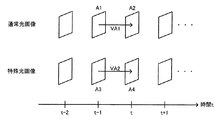
そのため、本出願人は、通常光画像の情報を用いて、特殊光画像における動き量(動きベクトル)を求める手法を提案する。図1のように、通常光画像と特殊光画像を同時に取得できる構成(例えば図3に示すような2板の撮像素子を持つ構成)であれば、通常光画像の過去フレームの画像(例えば図1のA1)と、通常光画像の現フレームの画像(図1のA2)とから通常光画像における動きベクトルである通常光動きベクトルVA1を取得する。この場合、特殊光画像の過去フレームの画像A3は通常光画像A1と同時に撮られたものであり、特殊光画像の現フレームの画像A4は通常光画像A2と同時に撮られたものであるから、求めたい特殊光動きベクトルVA2はVA1と基本的にほぼ一致することになる。よって、直接VA2を求めるのではなく、特殊光画像に比べて明るい通常光画像を用いてVA1を求めることで、より正確に特殊光動きベクトルVA2を求めることが可能になる。 Therefore, the present applicant proposes a method for obtaining a motion amount (motion vector) in a special light image using information on a normal light image. As shown in FIG. 1, if the configuration can acquire a normal light image and a special light image simultaneously (for example, a configuration having two image sensors as shown in FIG. 3), an image of a past frame of the normal light image (for example, FIG. 1). The normal light motion vector VA1, which is the motion vector in the normal light image, is acquired from A1) of 1 and the current frame image of the normal light image (A2 in FIG. 1). In this case, the image A3 of the past frame of the special light image was taken at the same time as the normal light image A1, and the image A4 of the current frame of the special light image was taken at the same time as the normal light image A2. The special light motion vector VA2 to be obtained basically coincides substantially with VA1. Therefore, instead of directly obtaining VA2, it is possible to obtain the special light motion vector VA2 more accurately by obtaining VA1 using a normal light image brighter than the special light image.
以上の本実施形態の基本的な手法について、まず第1の実施形態で説明する。また、第2の実施形態では、図2に示すように、通常光画像と特殊光画像を交互に取得する構成(例えば図14に示すような単板の撮像素子を持つ構成)の例を説明する。この場合、B4とB5の間の特殊光動きベクトルVB3を求めるにあたって、B1とB2の間の動きベクトルVB1と、B2とB3の間の動きベクトルVB2を求め、VB1とVB2を適当な形で合成する(例えば平均をとる)ことになる。 The basic method of the present embodiment will be described in the first embodiment. Further, in the second embodiment, as shown in FIG. 2, an example of a configuration that alternately obtains a normal light image and a special light image (for example, a configuration having a single-plate image sensor as shown in FIG. 14) will be described. To do. In this case, when obtaining the special light motion vector VB3 between B4 and B5, the motion vector VB1 between B1 and B2 and the motion vector VB2 between B2 and B3 are obtained, and VB1 and VB2 are combined in an appropriate form. (For example, take an average).
このような手法をとることで、暗くノイズが多い特殊光画像をそのまま用いるのではなく、明るくノイズが少ない通常光画像を用いて特殊光動きベクトルを求めることができる。従って、特殊光画像でも被写体の動き量を正確に求めることが可能になり、フレーム巡回型ノイズ低減処理において効率的なノイズ除去ができる。 By adopting such a method, it is possible to obtain a special light motion vector using a normal light image that is bright and has little noise, instead of using a dark and noisy special light image as it is. Accordingly, the amount of motion of the subject can be accurately obtained even in the special light image, and efficient noise removal can be performed in the frame cyclic noise reduction processing.
2.第1の実施形態 2. First embodiment
図3は、本実施形態にかかる画像処理装置を含む内視鏡システムの構成図である。内視鏡システムは、通常光光源101、挿入部102、ライトガイド103、レンズ201、ハーフミラー202、通常光撮像素子203、フィルタ204、特殊光撮像素子205、通常光画像A/D変換部211、特殊光画像A/D変換部212、通常光画像取得部213、特殊光画像取得部214、通常光動きベクトル情報算出部215、通常光ノイズ低減部217、特殊光ノイズ低減部218、出力部219、外部I/F220、制御部221、通常光画像保存部222、特殊光画像保存部223を含む。なお、構成はこれに限定されず、これらの構成要素の一部を省略するなどの種々の変形実施が可能である。
FIG. 3 is a configuration diagram of an endoscope system including the image processing apparatus according to the present embodiment. The endoscope system includes a
この画像処理装置は内視鏡用に適用するため、挿入部102は体内に挿入できるように湾曲が可能で細長い形状になっており、通常光光源101が照射する光は湾曲可能なライトガイド103を経由して、被写体100へ照射される。挿入部102の先端部には、レンズ201が配置されており、被写体100からの反射光はこのレンズ201を介して、ハーフミラー202により、二つの反射光に分離される。
Since this image processing apparatus is applied to an endoscope, the
1つの反射光は通常光撮像素子203に入る。この通常光撮像素子203は通常光画像を形成するためのベイヤ配列の色フィルタを持つ撮像素子である。本実施例では、図4に示す分光特性を持つRGBの色フィルタを持つ撮像素子を適用する(R(580nm〜700nm)、G(480nm〜600nm)、B(400nm〜500nm))。通常光撮像素子203は、光電変換により反射光を通常光アナログ画像信号へ変換する。
One reflected light enters the normal
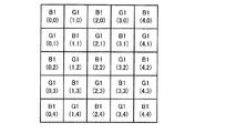
一方、もう1つの反射光は、狭帯域の色フィルタをもつ特殊光撮像素子205へ入る。本実施例では、図5に示す所定の狭帯域の透過率特性を持つ(G1(530nm〜550nm)、B1(390nm〜445nm))。特殊光撮像素子205は、図6に示すような特殊光画像を形成するための市松状配列の2種類の色フィルタを持つ撮像素子であり、狭帯域光を光電変換により特殊光アナログ画像信号(NBI画像信号)へ変換する。内視鏡診断の分野では、前記の狭帯域分光特性を持つ光は、血液中のヘモグロビンに吸収されやすいため、粘膜表層の毛細血管、粘膜微細模様の強調表示が実現できる。NBI画像信号は食道や大腸、胃などのがんの診断に効果が高い。
On the other hand, the other reflected light enters the special
通常光撮像素子203により変換された通常光アナログ画像信号は通常光画像A/D変換部211へ、特殊光撮像素子205により変換された特殊光アナログ画像信号は特殊光画像A/D変換部212へ出力される。
The normal light analog image signal converted by the normal
通常光画像A/D変換部211は、通常光画像取得部213、通常光動きベクトル情報算出部215、通常光ノイズ低減部217を介して出力部219へ接続している。通常光ノイズ低減部217は通常光画像保存部222と双方向に接続している。通常光画像保存部222は通常光動きベクトル情報算出部215へ接続している。特殊光画像A/D変換部212は、特殊光画像取得部214、特殊光ノイズ低減部218を介して出力部219へ接続している。特殊光ノイズ低減部218は、特殊光画像保存部223と双方向に接続している。通常光動きベクトル情報算出部215は特殊光ノイズ低減部218へ接続している。制御部221は、通常光画像A/D変換部211、特殊光画像A/D変換部212、通常光画像取得部213、特殊光画像取得部214、通常光動きベクトル情報算出部215、通常光ノイズ低減部217、特殊光ノイズ低減部218、出力部219、通常光画像保存部222、特殊光画像保存部223と双方向に接続している。外部I/F220は制御部221へ接続している。
The normal light image A /
通常光画像A/D変換部211は、通常光撮像素子203からの通常光アナログ画像信号をデジタル化して通常光デジタル画像信号(以下通常光画像信号と呼ぶ)として通常光画像取得部213へ転送する。一方、特殊光画像A/D変換部212は特殊光撮像素子205からの特殊光アナログ画像信号をデジタル化して特殊光デジタル画像信号(以下特殊光画像信号と呼ぶ)として特殊光画像取得部214へ転送する。
The normal light image A /
通常光画像取得部213は、制御部221の制御に基づき、通常光画像A/D変換部211からの通常光画像信号に対して画像処理を行う。本実施例では、公知のベイヤ補間処理(ベイヤ画像信号から3板画像信号へ変換する処理)、ホワイトバランス処理、カラーマネージメント処理、階調変換処理などを行う。処理後のRGB信号からなる通常光画像信号を通常光動きベクトル情報算出部215へ転送する。
The normal light
一方、特殊光画像取得部214は、制御部221の制御に基づき、特殊光画像A/D変換部212からの特殊光画像信号に対して画像処理を行う。本実施例では、まず図6に示す市松状配列のG1及びB1の2種類の色フィルタをもつ特殊光撮像素子により生成された特殊光画像信号を用いて、欠落画素の補間処理を行う。具体的には、同種類フィルタの欠落画素の周囲画素の平均信号値を算出し、信号値として欠落画素を補間する。例えば、下式(1)を用いて図6に示すG1(1,1)及びB1(2,1)を算出する。
On the other hand, the special light
G1(1,1)=(G1(1,0)+G1(0,1)+G1(2,1)+G1(1,2))/4
B1(2,1)=(B1(2,0)+B1(1,1)+B1(3,1)+B1(2,2))/4 ・・・・・(1)
G1 (1,1) = (G1 (1,0) + G1 (0,1) + G1 (2,1) + G1 (1,2)) / 4
B1 (2,1) = (B1 (2,0) + B1 (1,1) + B1 (3,1) + B1 (2,2)) / 4 (1)
前記の補間処理により全画素の2信号(G1、B1)の画像信号を生成する。次に、下式(2)を用いてNBI特殊光画像(NBI疑似カラー画像)を生成する。 An image signal of two signals (G1, B1) of all pixels is generated by the interpolation process. Next, an NBI special light image (NBI pseudo color image) is generated using the following equation (2).
Rch_v(x,y)=p1*G1(x,y)
Gch_v(x,y)=p2*B1(x,y)
Bch_v(x,y)=p3*B1(x,y) ・・・・・(2)
Rch_v (x, y) = p1 * G1 (x, y)
Gch_v (x, y) = p2 * B1 (x, y)
Bch_v (x, y) = p3 * B1 (x, y) (2)
上式(2)中のRch_v(x,y)はNBI特殊光画像信号のRチャンネルの信号値、Gch_v(x,y)はNBI特殊光画像信号のGチャンネルの信号値、Bch_v(x,y)はNBI特殊光画像信号のBチャンネルの信号値、B1(x,y)は前記補間処理後の全画素の2信号(G1、B1)の画像信号中のB1(狭帯域)画像の画素値、G1(x,y)は前記補間処理後の全画素の2信号(G1、B1)の画像信号中のG1(狭帯域)画像の画素値、(x,y)は画素が画像信号内の横軸と縦軸の座標位置、p1、p2、p3は所定係数である。 In the above equation (2), Rch_v (x, y) is the R channel signal value of the NBI special light image signal, Gch_v (x, y) is the G channel signal value of the NBI special light image signal, and Bch_v (x, y) ) Is the B channel signal value of the NBI special light image signal, and B1 (x, y) is the pixel value of the B1 (narrowband) image in the image signal of the two signals (G1, B1) of all the pixels after the interpolation processing. , G1 (x, y) is the pixel value of the G1 (narrowband) image in the image signal of the two signals (G1, B1) of all pixels after the interpolation processing, and (x, y) is the pixel value in the image signal The coordinate positions on the horizontal axis and the vertical axis, p1, p2, and p3 are predetermined coefficients.
続いて、前記NBI特殊光画像信号に対して、階調変換処理などを行う。処理後のRGB信号からなる特殊光画像信号(Rch_v,Gch_v,Bch_v)を特殊光ノイズ低減部218へ転送する。
Subsequently, gradation conversion processing or the like is performed on the NBI special light image signal. The special light image signals (Rch_v, Gch_v, Bch_v) composed of the processed RGB signals are transferred to the special light
図7は、通常光動きベクトル情報算出部215の構成の一例を示すもので、第1バッファー部301、第2バッファー部302、分割部303、類似度検出部304を含む。通常光画像取得部213は、第2バッファー部302、分割部303、類似度検出部304を介して、通常光ノイズ低減部217及び特殊光ノイズ低減部218へ接続している。通常光画像保存部222は、第1バッファー部301を介して類似度検出部304へ接続している。制御部221は、第1バッファー部301、第2バッファー部302、分割部303、類似度検出部304と双方向に接続している。
FIG. 7 shows an example of the configuration of the normal light motion vector
通常光画像取得部213は、制御部221の制御に基づき、画像処理済みの通常光画像信号を第2バッファー部302へ転送して、一時保存する。
Based on the control of the
通常光画像保存部222は、制御部221の制御により、保存しているノイズ低減済みの過去の通常光画像信号を第1バッファー部301へ転送して、一時保存する。この過去の通常光画像信号は、第2バッファー部302に保存されている通常光画像信号より時間的に直前に撮影され、時間距離が一番短い過去の通常光画像信号を指す。本実施例では、第1バッファー部301に保存されている過去の通常光画像信号を過去フレーム通常光画像信号と呼び、第2バッファー部302に保存されている通常光画像信号を現フレーム通常光画像信号と呼ぶ。
Under the control of the
分割部303は、制御部221の制御に基づき、第2バッファー部302にある現フレーム通常光画像信号を読み込んで分割処理を行う。具体的には、所定サイズを用いて現フレーム通常光画像信号に対して、複数のブロック領域に分割する。例えば、現フレーム通常光画像信号を同所定サイズのM×N(8×8、16×16、32×32など)の矩形領域に分割する。分割した複数のブロック領域の現フレーム通常光画像信号を類似度検出部304へ転送する。ブロック領域に関しては、矩形以外に多角形に設定してもよい。また、ユーザは外部I/F220を介して分割領域の形状を任意に指定してもよい。
Based on the control of the
類似度検出部304は、制御部221の制御に基づき、分割部303からの現フレーム通常光画像信号の各ブロック領域の通常光画像信号を用い、第1バッファー部301からのノイズ低減済みの過去フレーム通常光画像信号に対してテンプレートマッチング処理を行い、もっとも類似度の高いブロック領域を検出する。本実施例では、現フレーム通常光画像信号の各分割ブロック領域の通常光画像信号を用いて、ラスタスキャン順で公知のテンプレートマッチング処理を行い、対応する過去フレーム通常光画像信号の処理対象ブロック領域を抽出する。過去フレーム通常光画像信号の処理対象ブロック領域と、現フレーム通常光画像信号の処理対象ブロック領域の座標差(U,V)を通常光動きベクトル情報とする。
Based on the control of the
テンプレートとなる現フレーム画像信号のすべてのブロック領域のマッチング処理が完了後、通常光動きベクトル情報、現フレーム通常光画像信号を通常光ノイズ低減部217へ転送する。さらに、通常光動きベクトル情報を特殊光ノイズ低減部218へも転送する。
After the matching processing of all the block areas of the current frame image signal as a template is completed, the normal light motion vector information and the current frame normal light image signal are transferred to the normal light
本実施例では、図8の上段に示したように、過去フレーム通常光画像信号もブロック単位に分割し、ブロック領域ごとにテンプレートマッチング処理を行っているが、この構成に限定する必要がない。図8の下段に示したように、画素単位でブロックマッチング処理してもよい。例えば、処理対象画素を中心とする所定サイズのブロック領域の通常光画像信号を用いて、公知のテンプレートマッチング処理を行い、対応する過去フレーム通常光画像信号の処理対象ブロック領域を抽出する。続いて、当該処理対象画素とマッチングした過去フレーム通常光画像信号の処理対象ブロック領域の中心にある画素との座標差を処理対象画素の通常光動きベクトル情報とする。そうすることによって、マッチングの精度を向上させることができる。 In the present embodiment, as shown in the upper part of FIG. 8, the past frame normal light image signal is also divided into blocks, and the template matching process is performed for each block area. However, the present invention is not limited to this configuration. As shown in the lower part of FIG. 8, block matching processing may be performed on a pixel basis. For example, a known template matching process is performed using a normal light image signal of a block area of a predetermined size centered on the processing target pixel, and a processing target block area of the corresponding past frame normal light image signal is extracted. Subsequently, the coordinate difference from the pixel in the center of the processing target block area of the past frame normal light image signal matched with the processing target pixel is set as the normal light motion vector information of the processing target pixel. By doing so, the matching accuracy can be improved.
本実施例では、通常光ノイズ低減部217は、制御部221の制御に基づき、上記のマッチング結果(通常光動きベクトル)に応じて、輝度信号に対してノイズ低減処理を行う。通常光動きベクトルを用いて通常光画像信号のノイズ低減を行う手法については公知であるため、詳細な説明は省略する。また、通常光ノイズ低減部217は、公知の変換式でRGB信号から輝度信号及び色差信号に変換するため、色差信号に対しても、輝度信号に対するものと同様の方法でノイズ低減処理を行う。
In the present embodiment, the normal light
また、本実施例では、輝度信号を特徴量として、通常光動きベクトル情報を算出する構成となっているが、上述した式(2)で補間処理後のGch_v画像信号(図4に示すGの分光特性をもつ)を利用してもよい。 In the present embodiment, the normal light motion vector information is calculated using the luminance signal as a feature quantity. However, the Gch_v image signal (G of FIG. (Having spectral characteristics) may be used.
次に、特殊光ノイズ低減部218における、特殊光画像信号に対するノイズ低減処理について説明する。本実施例では、通常光画像信号と特殊光画像信号の解像度(画像サイズ)が同じ場合に対応する構成となっている。そのため、制御部221の制御により、通常光動きベクトル情報算出部215からの通常光動きベクトル情報をそのまま特殊光動きベクトル情報として、特殊光ノイズ低減部218へ転送し、前記通常光ノイズ低減部217と同じ内部構成で特殊光画像信号に対してノイズ低減処理してもよい。
Next, the noise reduction process for the special light image signal in the special light
この場合、特殊光ノイズ低減部218は、通常光動きベクトル情報算出部215からの通常光動きベクトル情報に基づき、特殊光画像保存部223からのノイズ低減済みの過去フレーム特殊光画像信号に対して、現フレーム特殊光画像信号の画素ごとの差分値(類似差分値)を算出する。続いて、図9に示している特殊光ノイズモデルを用いて、画素ごとに類似差分値を基に下式(3)を用いてノイズ量を算出し、下式(4)を用いてノイズ除去処理を行う。
In this case, the special light
S(x,y)=C(x,y)-B(x,y)
If(|S(x,y)|<S(T)) NS(x,y)=|S(x,y)|*Ka
Else NS(x,y)=NS(T) ・・・・・(3)
S (x, y) = C (x, y) -B (x, y)
If (| S (x, y) | <S (T)) NS (x, y) = | S (x, y) | * Ka
Else NS (x, y) = NS (T) (3)
ただし、C(x,y)は、過去フレーム特殊光画像信号の処理対象ブロック領域中の画素信号値、B(x,y)は、現フレーム特殊光画像信号の処理対象ブロック領域中の画素信号値、S(x,y)は画素ごとの類似差分値(マッチングした過去フレーム特殊光画像信号の処理対象ブロック領域と現フレーム特殊光画像信号の処理対象ブロック領域において、対応する画素ごとの差分値)、NS(x,y)は処理対象画素のノイズ量、Kaは類似差分値とノイズ成分の傾き係数、S(T)は類似差分閾値、NS(T)はノイズの閾値、S(Max)は類似差分最大値を表す。 However, C (x, y) is a pixel signal value in the processing target block area of the past frame special light image signal, and B (x, y) is a pixel signal in the processing target block area of the current frame special light image signal. The value S (x, y) is a similar difference value for each pixel (a difference value for each corresponding pixel in the processing target block region of the matched past frame special light image signal and the processing target block region of the current frame special light image signal) NS (x, y) is the amount of noise of the pixel to be processed, Ka is the similarity difference value and the slope coefficient of the noise component, S (T) is the similarity difference threshold, NS (T) is the noise threshold, and S (Max) Represents the maximum similarity difference.
ここで、S(x,y)は、動きベクトルも考慮した上での、過去フレーム特殊光画像信号(ノイズ除去済)と現フレーム特殊光画像信号(ノイズ未除去)の差分値であるため、理想的には、現フレーム特殊光画像信号に含まれるノイズ値となるはずである。しかし、過去フレーム特殊光画像信号のノイズが100パーセント除去されているわけではない上に、その他の要因(例えば照明の変化、被写体の変形等)により値が変動してしまい、S(x,y)をそのままノイズ値NS(x,y)とすることができない。 Here, since S (x, y) is a difference value between the past frame special light image signal (with noise removed) and the current frame special light image signal (with no noise removed) in consideration of the motion vector, Ideally, the noise value should be included in the current frame special light image signal. However, the noise of the special light image signal in the past frame is not 100% removed, and the value fluctuates due to other factors (for example, change in illumination, deformation of the subject, etc.), and S (x, y ) Cannot be directly used as the noise value NS (x, y).
そこで、図9に示した特殊光ノイズモデルを用いる。図9は、類似差分値と、類似差分値に含まれるノイズ量の関係をモデル化したものである。類似差分値がある閾値S(T)以下の場合には、ノイズ量は直線的に増加する。そして、類似差分値がS(T)より大きい場合には、ノイズ量は一定値NS(T)をとることになる。なお、類似差分値内のノイズ以外の成分とは、被写体の変形に起因する成分や、光源の変化に起因する成分等が考えられる。 Therefore, the special optical noise model shown in FIG. 9 is used. FIG. 9 models the relationship between the similarity difference value and the amount of noise included in the similarity difference value. When the similarity difference value is equal to or less than a certain threshold value S (T), the noise amount increases linearly. When the similarity difference value is larger than S (T), the noise amount takes a certain value NS (T). Note that components other than noise in the similarity difference value may be components resulting from subject deformation, components resulting from changes in the light source, and the like.
ノイズ量を求めることができたら、下式(4)を用いてノイズ低減処理を行う。 If the amount of noise can be obtained, noise reduction processing is performed using the following equation (4).
If(S(x,y)>0) E’(x,y)=B(x,y)+NS(x,y)
Else E’(x,y)=B(x,y)-NS(x,y) ・・・・・(4)
ただし、E’(x,y)はノイズ低減処理後の特殊光画像信号値を表す。
If (S (x, y)> 0) E '(x, y) = B (x, y) + NS (x, y)
Else E '(x, y) = B (x, y) -NS (x, y) (4)
However, E ′ (x, y) represents the special light image signal value after the noise reduction processing.
上述したようにS(x,y)=過去フレーム−現フレームであるから、S(x,y)>0の場合とは、過去フレーム>現フレームとなり、現フレームにマイナスのノイズが含まれている可能性が高い。よって式(3)で求めたノイズ値NS(x,y)を現フレーム特殊光画像信号B(x,y)に加算する。逆にS(x,y)≦0の場合は、過去フレーム≦現フレームとなり、現フレームにプラスのノイズが含まれている可能性が高い。よって、B(x,y)からNS(x,y)を減算する。 As described above, since S (x, y) = past frame-current frame, when S (x, y)> 0, the past frame> current frame, and the current frame includes negative noise. There is a high possibility. Therefore, the noise value NS (x, y) obtained by Expression (3) is added to the current frame special light image signal B (x, y). Conversely, when S (x, y) ≦ 0, the past frame ≦ the current frame, and there is a high possibility that positive noise is included in the current frame. Therefore, NS (x, y) is subtracted from B (x, y).
以上の処理により、特殊光画像(現フレーム特殊光画像信号)に対して適度な強さでノイズ低減処理を行うことができる。 With the above processing, it is possible to perform noise reduction processing with an appropriate strength on the special light image (current frame special light image signal).
しかし、特殊光画像信号と通常光画像信号の解像度は異なることは普通である。この場合、上述したように通常光画像信号から算出した通常光動きベクトル情報をそのまま特殊光画像信号のノイズ低減処理に適用することはできない。 However, it is normal that the resolutions of the special light image signal and the normal light image signal are different. In this case, as described above, the normal light motion vector information calculated from the normal light image signal cannot be directly applied to the noise reduction process of the special light image signal.
図10は、本願の第1の実施形態の変形例の構成図である。内視鏡システムは、通常光光源101、挿入部102、ライトガイド103、レンズ201、ハーフミラー202、通常光撮像素子203、フィルタ204、特殊光撮像素子205、通常光画像A/D変換部211、特殊光画像A/D変換部212、通常光画像取得部213、特殊光画像取得部214、通常光動きベクトル情報算出部215、特殊光動きベクトル情報算出部216、通常光ノイズ低減部217、特殊光ノイズ低減部218、出力部219、外部I/F220、制御部221、通常光画像保存部222、特殊光画像保存部223を含む。
FIG. 10 is a configuration diagram of a modification of the first embodiment of the present application. The endoscope system includes a
通常光撮像素子203により変換された通常光アナログ画像信号は通常光画像A/D変換部211へ、特殊光撮像素子205により変換された特殊光アナログ画像信号は特殊光画像A/D変換部212へ出力される。
The normal light analog image signal converted by the normal
通常光画像A/D変換部211は、通常光画像取得部213、通常光動きベクトル情報算出部215、通常光ノイズ低減部217を介して出力部219へ接続している。通常光ノイズ低減部217は通常光画像保存部222と双方向に接続している。通常光画像保存部222は通常光動きベクトル情報算出部215へ接続している。特殊光画像A/D変換部212は、特殊光画像取得部214、特殊光動きベクトル情報算出部216、特殊光ノイズ低減部218を介して出力部219へ接続している。特殊光ノイズ低減部218は、特殊光画像保存部223と双方向に接続している。特殊光画像保存部223は特殊光動きベクトル情報算出部216へ接続している。通常光動きベクトル情報算出部215は特殊光動きベクトル情報算出部216へ接続している。制御部221は、通常光画像A/D変換部211、特殊光画像A/D変換部212、通常光画像取得部213、特殊光画像取得部214、通常光動きベクトル情報算出部215、特殊光動きベクトル情報算出部216、通常光ノイズ低減部217、特殊光ノイズ低減部218、出力部219、通常光画像保存部222、特殊光画像保存部223と双方向に接続している。外部I/F220は制御部221へ接続している。
The normal light image A /
本変形例において、第1の実施形態と同じ構成に関する内容を省略し、異なる部分のみを説明する。 In this modification, the content regarding the same structure as 1st Embodiment is abbreviate | omitted, and only a different part is demonstrated.
本変形例では、制御部221の制御に基づき通常光動きベクトル情報算出部215からの通常光動きベクトル情報と通常光画像信号の画像サイズ(I,J)を特殊光動きベクトル情報算出部216へ転送する。
In the present modification, the normal light motion vector information from the normal light motion vector
続いて、特殊光画像信号と通常光画像信号の解像度の比較情報に基づき、通常光画像信号から算出した動きベクトルを補正し、特殊光動きベクトルとして特殊光画像信号からノイズ低減処理する構成となっている。 Subsequently, based on the comparison information of the resolution of the special light image signal and the normal light image signal, the motion vector calculated from the normal light image signal is corrected, and noise reduction processing is performed from the special light image signal as the special light motion vector. ing.
図11は、特殊光動きベクトル情報算出部216の構成の一例を示すもので、第3バッファー部501、補正係数算出部502、補正部503、及びRAM504を含む。特殊光画像取得部214は、補正係数算出部502及び補正部503を介して特殊光ノイズ低減部218へ接続している。通常光動きベクトル情報算出部215は、RAM504を介して、補正係数算出部502及び補正部503へ接続している。特殊光画像保存部223は、第3バッファー部501を介して補正部503へ接続している。通常光動きベクトル情報算出部215はRAM504へ接続している。制御部221は、第3バッファー部501、補正係数算出部502、補正部503及びRAM504と双方向に接続している。
FIG. 11 shows an example of the configuration of the special light motion vector
特殊光画像取得部214は、制御部221の制御に基づき、画像処理済みの特殊光画像信号を補正係数算出部502へ、特殊光画像信号の画像サイズ(K,L)をRAM504へ転送して、一時保存する。また、通常光動きベクトル情報算出部215からの通常光動きベクトル情報と通常光画像信号の画像サイズ(I,J)をもRAM504へ転送して、一時保存する。
Based on the control of the
特殊光画像保存部223は、制御部221の制御に基づき、保存しているノイズ低減済みの過去の特殊光画像信号を第3バッファー部501へ転送して、一時保存する。この過去の特殊光画像信号は、特殊光画像取得部214からの特殊光画像信号より時間的に直前に撮影され、時間距離が一番短い過去の特殊光画像信号を指す。本実施例では、第3バッファー部501に保存されている過去の特殊光画像信号を過去フレーム特殊光画像信号と呼び、特殊光画像取得部214からの特殊光画像信号を現フレーム特殊光画像信号と呼ぶ。
Based on the control of the
補正係数算出部502は、制御部221の制御に基づき、RAM504からの通常光画像信号の画像サイズ(I,J)と特殊光画像取得部214からの特殊画像信号の画像サイズ(K,L)を用いて、下式(5)により補正係数を算出し、現フレーム特殊光画像信号と一緒に補正部503へ転送する。
Based on the control of the
PowerX=K/I
PowerY=L/J ・・・・・(5)
PowerX = K / I
PowerY = L / J (5)
本実施例では、補正部503は、制御部221の制御により、上式(5)により算出した補正係数PowerX及びPowerYを用いて、RAM504からの通常光動きベクトル情報に基づき、下式(6)で特殊光動きベクトルを算出する。
In this embodiment, the
u=U*PowerX
v=V*PowerY ・・・・・(6)
u = U * PowerX
v = V * PowerY (6)
ただし、(u,v)は特殊光画像信号のあるブロック領域に対応する動きベクトル(特殊光動きベクトル情報)、(U,V)はこの特殊光画像信号のブロック領域に対応する通常光画像信号のブロック領域の動きベクトル(通常光動きベクトル情報)である。 However, (u, v) is a motion vector (special light motion vector information) corresponding to a block area having a special light image signal, and (U, V) is a normal light image signal corresponding to the block area of the special light image signal. The motion vector of the block area (normal light motion vector information).
すべての特殊光画像信号のブロック領域の特殊光動きベクトルを算出した後、特殊光ノイズ低減部218へ転送する。
After calculating the special light motion vector in the block area of all the special light image signals, it is transferred to the special light
特殊光ノイズ低減部218は、制御部221の制御に基づき、前記現フレーム特殊光画像信号、過去フレーム特殊光画像信号及ぶ特殊光画像信号のブロック領域の動きベクトル情報を用いて、特殊光ノイズ低減処理を行う。特殊光ノイズ低減処理の構成は、上述した第1の実施形態と同様のため、ここでの説明は省略する。
The special light
このように、通常光画像信号から通常光動きベクトルを算出し、それを補正した上で特殊光動きベクトルを取得してノイズ低減処理を行うことが可能となり、特殊光画像信号のノイズ低減効果を高めることができるため、特殊光画像信号での診断能力を向上することにつながる。 In this way, it is possible to calculate the normal light motion vector from the normal light image signal, correct it, acquire the special light motion vector, and perform the noise reduction processing, and to reduce the noise reduction effect of the special light image signal. Therefore, it is possible to improve the diagnostic ability with the special light image signal.
以上説明した本実施形態における画像信号処理は、ハードウェアにより実現しているが、このような構成に限定される必要がない。例えば、A/D変換処理後の画像信号を未処理のままのロー(RAW)データとしてメモリカードなどの記録媒体に記録するとともに、制御部221からの撮像時の情報(AGC感度やホワイトバランス係数など)をヘッダ情報として記録媒体に記録しておく。そして、別途のソフトウェアである画像信号処理プログラムをコンピュータに実行させて、記録媒体の情報をコンピュータに読み取らせ、処理することも可能である。なお、撮像部からコンピュータへの各種情報の転送は、上述と同様に、記録媒体を介して行うものに限定されず、通信回線などを介して行うようにしても構わない。
Although the image signal processing in the present embodiment described above is realized by hardware, it need not be limited to such a configuration. For example, the image signal after A / D conversion processing is recorded as unprocessed raw (RAW) data on a recording medium such as a memory card, and information (AGC sensitivity and white balance coefficient) at the time of imaging from the
図12は、本実施形態における画像信号処理プログラムによる処理を示すフローチャートである。 FIG. 12 is a flowchart showing processing by the image signal processing program in the present embodiment.
この処理を開始すると、まず、S1にて、通常光画像信号および特殊光画像信号のローデータ、画像信号のサイズを含むヘッダ情報などを読み込むとともに、該画像信号処理プログラムが予め備えている階調特性係数などの情報も読み込んで、S2へ進む。また、ヘッダ情報や階調特性係数などの情報をメモリ上に一時保存する。この処理は、撮像装置である画像処理装置において、被写体を撮影した通常光画像信号および特殊光画像信号を取得する処理に相当している。 When this process is started, first, in S1, the raw data of the normal light image signal and the special light image signal, header information including the size of the image signal, and the like are read, and the gradation provided in advance in the image signal processing program. Information such as a characteristic coefficient is also read, and the process proceeds to S2. Also, information such as header information and gradation characteristic coefficients is temporarily stored in the memory. This process corresponds to a process of acquiring a normal light image signal and a special light image signal obtained by photographing an object in an image processing apparatus that is an imaging apparatus.
次に、S2にて、読み込んだ画像信号の種類を判別する。通常光画像信号の場合、S3へ進む。特殊光画像信号の場合、S6へ進む。そして、S3にて、通常光画像信号に対して、公知のベイヤ補間処理(ベイヤ画像信号から三板画像信号へ変換)、ホワイトバランス処理、カラーマネージメント処理、階調変換処理などを行う。処理後、S4へ進む。これは、図3の通常光画像取得部213の処理に相当する。
Next, in S2, the type of the read image signal is determined. In the case of a normal light image signal, the process proceeds to S3. In the case of a special light image signal, the process proceeds to S6. In S3, a known Bayer interpolation process (conversion from a Bayer image signal to a three-plate image signal), a white balance process, a color management process, a gradation conversion process, and the like are performed on the normal light image signal. After processing, the process proceeds to S4. This corresponds to the processing of the normal light
続いて、S4にて、時系列的に過去フレームの通常光画像信号と現フレームの通常光画像信号を用いて、通常光動きベクトル情報を算出する。この通常光動きベクトル情報を一時メモリに保存する。処理後、S5へ進む。これは、図3の通常光動きベクトル情報算出部215の処理に相当する。それから、S5にて、通常光画像信号及び通常光動きベクトル情報を用いて通常光ノイズ低減処理を行う。処理後、ノイズ低減処理後の通常光画像信号をメモリに保存する。これは、図3の通常光ノイズ低減部217の処理に相当する。処理後、ノイズ低減処理後の通常光画像信号をメモリに保存する。
Subsequently, in S4, the normal light motion vector information is calculated using the normal light image signal of the past frame and the normal light image signal of the current frame in time series. The normal light motion vector information is stored in a temporary memory. After processing, the process proceeds to S5. This corresponds to the processing of the normal light motion vector
一方、S6にて、特殊光画像信号に対して画像処理を行う。特殊光画像信号が図6に示す市松状配列のG1及びB1の構成となっているため、式(1),(2)に基づき補間処理を実施し、公知の階調変換処理などを行う。処理終了後、S7へ進む。これは、図3の特殊光画像取得部214の処理に相当する。続いて、S7にて、メモリから通常光動きベクトル情報を読み込んで、S8へ進む。そして、S8にて、通常光動きベクトル情報を用いて特殊光動きベクトルを算出する。処理後、S9へ進む。これは、図10の特殊光動きベクトル情報算出部216の処理に相当する。
On the other hand, in S6, image processing is performed on the special light image signal. Since the special light image signal has the checkered arrangement G1 and B1 shown in FIG. 6, interpolation processing is performed based on the formulas (1) and (2), and known gradation conversion processing is performed. After the process is completed, the process proceeds to S7. This corresponds to the processing of the special light
次に、S9にて、特殊光画像信号及び特殊光動きベクトル情報を用いて特殊光ノイズ低減処理を行う。処理後、ノイズ低減処理後の特殊光画像信号をメモリに保存する。これは、図3の特殊光ノイズ低減部218の処理に相当する。
Next, in S9, special light noise reduction processing is performed using the special light image signal and the special light motion vector information. After the processing, the special light image signal after the noise reduction processing is stored in the memory. This corresponds to the processing of the special light
続いて、図13を用いて、図12のS8における特殊光動きベクトルの算出処理の詳細について説明する。 Next, the details of the special light motion vector calculation process in S8 of FIG. 12 will be described with reference to FIG.
この処理を開始すると、まず、S16にて、メモリから通常光画像信号の画像サイズ(I,J)と特殊画像信号の画像サイズ(K,L)を読み込み、補正係数を算出して(式(5))、S17へ進む。これは、図11の補正係数算出部502の処理に相当する。次に、S17にて、S16にて算出された補正係数を用いて、特殊光動きベクトルを算出する(式(6))。処理終了後、図12に示した処理へ復帰する。これは、図11の補正部503の処理に相当する。
When this process is started, first, in S16, the image size (I, J) of the normal light image signal and the image size (K, L) of the special image signal are read from the memory, and a correction coefficient is calculated (formula ( 5)), Proceed to S17. This corresponds to the processing of the correction
さらに、本実施例では、リアルタイムに画像信号処理を行うため、現フレーム通常光/特殊光画像信号及び過去フレーム通常光/特殊光画像信号を用いて、動きベクトルを算出し、それを補正した上でノイズ低減処理を行う構成となっているが、この構成に限定する必要がない。例えば、カプセル内視鏡画像信号処理の場合、一旦カプセル内視鏡で撮像した画像信号を記録媒体に保存する。その後、別途のソフトウェアで記録媒体から画像信号を読み込み、現像処理を行う。この場合、用いる画像信号は、現フレーム通常光/特殊光画像信号及び過去フレーム通常光/特殊光画像信号に限定されず、時系列的に現フレーム通常光/特殊光画像信号より遅く撮像された、将来フレーム通常光/特殊光画像信号を用いて動きベクトルを算出し、ノイズ低減処理を行うように構成してもよい。また、本実施例では、現フレーム通常光/特殊光画像信号及び1枚の過去フレーム通常光/特殊光画像信号を用いて動きベクトルを算出し、ノイズ低減処理を行うが、複数枚の過去フレーム(または将来フレーム)通常光/特殊光画像信号を用いて動きベクトルを算出し、ノイズ低減処理を行う構成にしてもよい。 Further, in this embodiment, since image signal processing is performed in real time, a motion vector is calculated and corrected using the current frame normal light / special light image signal and the past frame normal light / special light image signal. However, the present invention is not limited to this configuration. For example, in the case of capsule endoscope image signal processing, an image signal once captured by a capsule endoscope is stored in a recording medium. Thereafter, the image signal is read from the recording medium with separate software, and development processing is performed. In this case, the image signal to be used is not limited to the current frame normal light / special light image signal and the past frame normal light / special light image signal, but is imaged later than the current frame normal light / special light image signal in time series. The motion vector may be calculated using the future frame normal light / special light image signal, and noise reduction processing may be performed. In this embodiment, the motion vector is calculated using the current frame normal light / special light image signal and one past frame normal light / special light image signal, and noise reduction processing is performed. (Or future frame) A motion vector may be calculated using a normal light / special light image signal, and a noise reduction process may be performed.
以上の本実施形態では、画像処理装置は、図3に示すように、通常光画像を取得する通常光画像取得部213と、特殊光画像を取得する特殊光画像取得部214と、通常光画像内の特徴量に基づいて、複数の通常光画像間の動きベクトル情報を算出する通常光動きベクトル情報算出部215と、通常光動きベクトル情報に基づいて特殊光画像中のノイズ量を低減するノイズ低減部(図3における特殊光ノイズ低減部218)と、を含む。
In the above embodiment, as shown in FIG. 3, the image processing apparatus includes a normal light
ここで、通常光画像とは、図4に示すようなRGBの信号に対応する白色光の波長帯域における情報を含む画像であり、特殊光画像とは、図5に示すような、特定の波長帯域における情報を含む画像である。また、通常光動きベクトル情報とは、複数の通常光画像の間の動きベクトルそのものであってもよいし、動きベクトルと等価な情報であってもよい。例えば通常光動きベクトル情報は、通常光動きベクトルそのものを用いた場合と同等の作用・効果を得ることができる情報であればよい。 Here, the normal light image is an image including information in the wavelength band of white light corresponding to the RGB signal as shown in FIG. 4, and the special light image is a specific wavelength as shown in FIG. It is an image including information in a band. The normal light motion vector information may be a motion vector itself between a plurality of normal light images, or may be information equivalent to a motion vector. For example, the normal light motion vector information may be information that can obtain the same operation and effect as when the normal light motion vector itself is used.
これにより、通常光画像及び特殊光画像を取得し、通常光画像から通常光動きベクトル情報を算出することで、特殊光画像中のノイズ量を低減する画像処理装置を実現できる。よって、複数の特殊光画像間の動きベクトル情報を用いたノイズ低減処理(例えば、過去フレーム特殊光画像と、現フレーム特殊光画像の差分をとるフレーム巡回型ノイズ低減処理等)において発生する、特殊光画像が暗いため、正確な動きベクトル情報(特殊光動きベクトル情報)を求められないという問題を、明るい通常光画像による通常光動きベクトル情報を利用することで解決すること等が可能になる。そのため、効率的にノイズ低減を行うことができる。 Accordingly, an image processing apparatus that reduces the amount of noise in the special light image can be realized by acquiring the normal light image and the special light image and calculating the normal light motion vector information from the normal light image. Therefore, special noise that occurs in noise reduction processing using motion vector information between multiple special light images (for example, frame cyclic noise reduction processing that takes the difference between past frame special light images and current frame special light images) The problem that accurate motion vector information (special light motion vector information) cannot be obtained because the light image is dark can be solved by using normal light motion vector information from a bright normal light image. Therefore, noise can be reduced efficiently.
また、通常光画像取得部213は、第1のタイミングにおいて第1通常光画像を取得し、第2のタイミングにおいて第2通常光画像を取得する。そして、通常光動きベクトル情報算出部215は、第1通常光画像内の特徴量と、第2通常光画像内の特徴量とに基づいて、第1通常光画像と第2通常光画像との間の通常光動きベクトル情報を算出してもよい。具体的には、第1通常光画像内の特徴量と、第2通常光画像内の特徴量を用いて図8に示すようなマッチング処理を行うことで、通常光動きベクトル情報を算出してもよい。
The normal light
これにより、タイミング(例えばフレーム)の異なる通常光画像を用いて通常光動きベクトル情報を算出することが可能になる。具体的には、図8に示したように、ブロック単位・画素単位でのマッチング処理を行うことで、通常光動きベクトル情報を算出することができる。 This makes it possible to calculate normal light motion vector information using normal light images with different timing (for example, frames). Specifically, as shown in FIG. 8, the normal light motion vector information can be calculated by performing matching processing in units of blocks and pixels.
また、画像処理装置は、図10に示すように、通常光動きベクトル情報に基づいて特殊光動きベクトル情報を算出する特殊光動きベクトル情報算出部216を含んでもよい。そして特殊光動きベクトル情報算出部216は、図11に示すように、通常光動きベクトル情報を、通常光画像及び特殊光画像に基づいて補正する補正部503を含んでもよい。具体的には、補正部503は、通常光画像の解像度と特殊光画像の解像度との比較結果に基づいて補正を行ってもよい。さらに具体的には、通常光画像の解像度と特殊光画像の解像度の比較結果により特定される拡大率又は縮小率を、通常光動きベクトル情報に乗算することで補正を行ってもよい。
In addition, as illustrated in FIG. 10, the image processing apparatus may include a special light motion vector
ここで、特殊光動きベクトル情報とは、複数の特殊光画像の間の動きベクトルそのものであってもよいし、動きベクトルと等価な情報であってもよい。例えば特殊光動きベクトル情報は、特殊光動きベクトルそのものを用いた場合と同等の作用・効果を得ることができる情報であればよい。 Here, the special light motion vector information may be a motion vector itself between a plurality of special light images, or may be information equivalent to a motion vector. For example, the special light motion vector information may be information that can obtain the same operation and effect as when the special light motion vector itself is used.
これにより、通常光動きベクトル情報をそのまま利用するのではなく、適切な補正処理を施した上で利用することが可能になる。具体的には例えば、図10に示したように2板の撮像素子を持つような構成では、通常光画像の解像度と特殊光画像の解像度が異なる可能性がある。そのようなときには、解像度の比に応じた補正を行う。具体的には例えば、上述した式(5)、(6)のような補正を行えばよい。 As a result, the normal light motion vector information is not used as it is, but can be used after appropriate correction processing is performed. Specifically, for example, in a configuration having two image sensors as shown in FIG. 10, the resolution of the normal light image and the resolution of the special light image may be different. In such a case, correction according to the resolution ratio is performed. Specifically, for example, the corrections described in the above formulas (5) and (6) may be performed.
また、特殊光画像取得部214は、第1のタイミングで第1特殊光画像を取得し、第2のタイミングで第2特殊光画像を取得する。そして、ノイズ低減部(図3における特殊光ノイズ低減部218)は、第1特殊光画像内に第1の処理対象領域を設定するとともに、通常光動きベクトル情報に基づいて第2特殊光画像内に第1の処理対象領域に対応する第2の処理対象領域を設定する。その上で、第1の処理対象領域の特徴量と、第2の処理対象領域の特徴量とに基づいて、第1の処理対象領域又は第2の処理対象領域のノイズ量を低減する。
The special light
これにより、タイミング(例えばフレーム)の異なる特殊光画像を取得した上で、通常光動きベクトル情報に基づいて、それぞれの画像内に対応する領域を設定することが可能となる。そして、対応する2つの領域の特徴量を用いて、どちらかの領域のノイズ低減処理を行うことができる。ノイズ低減処理が可能となるのは、2つの領域は動きベクトル情報に基づいて対応付けられたものである以上、撮像されている被写体は理想的には同一のものであり、特徴量の比較結果とは、被写体に起因する成分が抑止され、ノイズに起因する成分が主に含まれていると考えられることによる。 As a result, after acquiring special light images with different timings (for example, frames), it is possible to set a corresponding region in each image based on the normal light motion vector information. And the noise reduction process of either area | region can be performed using the feature-value of two corresponding areas. The noise reduction processing is possible because the two areas are associated based on the motion vector information, so that the captured subject is ideally the same, and the comparison result of the feature amount This is because the component due to the subject is suppressed and the component due to noise is mainly included.
また、ノイズ低減部(特殊光ノイズ低減部218)は、第1の処理対象領域の特徴量と、第2の処理対象領域の特徴量の差分値に基づいて、第2の処理対象領域に含まれるべき第2ノイズ量を推定するノイズ量推定部を含んでもよい。そして、ノイズ低減部は、ノイズ量推定部が推定した第2ノイズ量と、第2の処理対象領域の特徴量との差分を求めることで、第2の処理対象領域のノイズ量を低減してもよい。 The noise reduction unit (special light noise reduction unit 218) is included in the second processing target region based on the difference value between the feature amount of the first processing target region and the feature amount of the second processing target region. You may include the noise amount estimation part which estimates the 2nd noise amount which should be performed. The noise reduction unit reduces the noise amount in the second processing target region by obtaining a difference between the second noise amount estimated by the noise amount estimation unit and the feature amount of the second processing target region. Also good.
ここで、ノイズ量推定部は、第1の処理対象領域の特徴量と第2の処理対象領域の特徴量との差分値と、推定すべき第2ノイズ量との対応関係を示す、対応関係情報(例えば図9に示すようなノイズモデルであってもよいし、テーブルデータであってもよい)を取得し、取得した対応関係情報に基づいてノイズ量を推定する。 Here, the noise amount estimation unit indicates a correspondence relationship between the difference value between the feature amount of the first processing target region and the feature amount of the second processing target region and the second noise amount to be estimated. Information (for example, a noise model as shown in FIG. 9 or table data) may be acquired, and the amount of noise is estimated based on the acquired correspondence information.
これにより、ノイズ低減部は、特徴量の差分値からノイズ量を推定し、推定したノイズ量と処理対象領域の特徴量の差分を求めることで、ノイズ低減処理を行うことが可能となる。特徴量の差分値からのノイズ量の推定には、図9に示したようなノイズモデル等を使うことで、より適切なノイズ低減を行うことができる。 Thereby, the noise reduction unit can perform the noise reduction process by estimating the noise amount from the difference value of the feature amount and obtaining the difference between the estimated noise amount and the feature amount of the processing target region. For the estimation of the noise amount from the difference value of the feature amount, a more appropriate noise reduction can be performed by using a noise model as shown in FIG.
また、ノイズ低減部(特殊光ノイズ低減部218)は、第1の処理対象領域の特徴量と第2の処理対象領域の特徴量との差分値を、ゼロに近づけることで、第1の処理対象領域又は第2の処理対象領域のノイズ量を低減してもよい。 In addition, the noise reduction unit (special light noise reduction unit 218) performs the first processing by bringing the difference value between the feature amount of the first processing target region and the feature amount of the second processing target region close to zero. The amount of noise in the target region or the second processing target region may be reduced.
これにより、上述したノイズモデル等を使わなくても、ノイズ量を低減することが可能となる。この場合は、特徴量の差分値は全てノイズ成分であるという、理想的な状況を仮定していることになる。 As a result, the amount of noise can be reduced without using the noise model described above. In this case, an ideal situation is assumed in which all the difference values of the feature amounts are noise components.
また、特定の波長帯域とは、白色光の波長帯域よりも狭い帯域である。具体的には特殊光画像は生体内画像であり、特定の波長帯域とは、血液中のヘモグロビンに吸収される波長の波長帯域である。さらに具体的には、390nm〜445nmまたは530nm〜550nmの波長帯域である。 The specific wavelength band is a band narrower than the wavelength band of white light. Specifically, the special light image is an in-vivo image, and the specific wavelength band is a wavelength band of a wavelength that is absorbed by hemoglobin in blood. More specifically, the wavelength band is 390 nm to 445 nm or 530 nm to 550 nm.
これにより、生体の表層部及び、深部に位置する血管の構造を観察することが可能になる。また得られた信号を特定のチャンネル(R,G,B)に入力することで、扁平上皮癌等の通常光では視認が難しい病変などを褐色等で表示することができ、病変部の見落としを抑止することができる。なお、390nm〜445nmまたは530nm〜550nmとはヘモグロビンに吸収されるという特性及び、それぞれ生体の表層部または深部まで到達するという特性から得られた波長である。ただし、この場合の波長帯域はこれに限定されず、例えばヘモグロビンによる吸収と生体の表層部又は深部への到達に関する実験結果等の変動要因により、波長帯域の下限値が0〜10%程度減少し、上限値が0〜10%程度上昇することも考えられる。 Thereby, it becomes possible to observe the structure of the blood vessel located in the surface layer part and the deep part of the living body. In addition, by inputting the obtained signals to specific channels (R, G, B), lesions that are difficult to see with normal light such as squamous cell carcinoma can be displayed in brown, etc. Can be deterred. Note that 390 nm to 445 nm or 530 nm to 550 nm are wavelengths obtained from the characteristic of being absorbed by hemoglobin and the characteristic of reaching the surface layer or the deep part of the living body, respectively. However, the wavelength band in this case is not limited to this. For example, the lower limit of the wavelength band is reduced by about 0 to 10% due to the variation factors such as the absorption by hemoglobin and the experimental results regarding the arrival of the living body on the surface layer or the deep part. It is also conceivable that the upper limit value increases by about 0 to 10%.
また、特殊光画像は生体内を写した生体内画像であってもよい。そして生体内画像に含まれる特定の波長帯域とは、蛍光物質が発する蛍光の波長帯域であってもよい。具体的には490nm〜625nmの波長帯域である。 Further, the special light image may be an in-vivo image obtained by copying the inside of the living body. The specific wavelength band included in the in-vivo image may be a wavelength band of fluorescence emitted from the fluorescent material. Specifically, the wavelength band is 490 nm to 625 nm.
これにより、AFIと呼ばれる蛍光観察が可能となる。励起光(390nm〜470nm)を照射することで、コラーゲンなどの蛍光物質からの自家蛍光を観察することができる。このような観察では病変を正常粘膜とは異なった色調で強調表示することができ、病変部の見落としを抑止すること等が可能になる。なお490nm〜625nmという波長は、前述の励起光を照射した際、コラーゲンなどの蛍光物質が発する自家蛍光の波長帯域を示したものである。ただし、この場合の波長帯域はこれに限定されず、例えば蛍光物質が発する蛍光の波長帯域に関する実験結果等の変動要因により、波長帯域の下限値が0〜10%程度減少し、上限値が0〜10%程度上昇することも考えられる。また、ヘモグロビンに吸収される波長帯域(540nm〜560nm)を同時に照射し、擬似カラー画像を生成してもよい。 This enables fluorescence observation called AFI. By irradiating with excitation light (390 nm to 470 nm), autofluorescence from a fluorescent substance such as collagen can be observed. In such observation, the lesion can be highlighted with a color tone different from that of the normal mucous membrane, and the oversight of the lesion can be suppressed. The wavelength of 490 nm to 625 nm indicates the wavelength band of autofluorescence emitted from a fluorescent substance such as collagen when irradiated with the excitation light described above. However, the wavelength band in this case is not limited to this. For example, the lower limit of the wavelength band is reduced by about 0 to 10% and the upper limit is 0 due to a variation factor such as an experimental result regarding the wavelength band of the fluorescence emitted by the fluorescent material. A rise of about 10% is also conceivable. Alternatively, a pseudo color image may be generated by simultaneously irradiating a wavelength band (540 nm to 560 nm) absorbed by hemoglobin.
また、特殊光画像は生体内を写した生体内画像であってもよい。そして生体内画像に含まれる特定の波長帯域とは、赤外光の波長帯域であってもよい。具体的には790nm〜820nmまたは905nm〜970nmの波長帯域である。 Further, the special light image may be an in-vivo image obtained by copying the inside of the living body. The specific wavelength band included in the in-vivo image may be a wavelength band of infrared light. Specifically, the wavelength band is 790 nm to 820 nm or 905 nm to 970 nm.
これにより、IRIと呼ばれる赤外光観察が可能となる。赤外光が吸収されやすい赤外指標薬剤であるICG(インドシアニングリーン)を静脈注射した上で、上記波長帯域の赤外光を照射することで、人間の目では視認が難しい粘膜深部の血管や血流情報を強調表示することができ、胃癌の深達度診断や治療方針の判定などが可能になる。なお790nm〜820nmという波長は赤外指標薬剤の吸収がもっとも強いという特性から、905nm〜970nmという波長は赤外指標薬剤の吸収がもっとも弱いという特性から求められたものである。ただし、この場合の波長帯域はこれに限定されず、例えば赤外指標薬剤の吸収に関する実験結果等の変動要因により、波長帯域の下限値が0〜10%程度減少し、上限値が0〜10%程度上昇することも考えられる。 Thereby, infrared light observation called IRI becomes possible. Intravenous injection of ICG (Indocyanine Green), an infrared index drug that easily absorbs infrared light, and then irradiating with infrared light in the above wavelength band, it is difficult to visually recognize the blood vessels in the deep mucosa And blood flow information can be highlighted, making it possible to diagnose the depth of gastric cancer and determine the treatment policy. The wavelength of 790 nm to 820 nm is obtained from the characteristic that the absorption of the infrared index drug is the strongest, and the wavelength of 905 nm to 970 nm is determined from the characteristic that the absorption of the infrared index drug is the weakest. However, the wavelength band in this case is not limited to this. For example, the lower limit of the wavelength band is reduced by about 0 to 10% and the upper limit is 0 to 10 due to a variation factor such as an experimental result regarding absorption of the infrared index drug. It can also be expected to increase by about%.
また、本実施形態は、通常光画像取得部213と、特殊光画像取得部214と、通常光動きベクトル情報算出部215と、ノイズ低減部(特殊光ノイズ低減部218)としてコンピュータを機能させるプログラムに関係する。
Further, the present embodiment is a program that causes a computer to function as a normal light
これにより、例えばカプセル型内視鏡などのように、まず画像データを蓄積し、その後、蓄積された画像データに対してPC等のコンピューターシステムでソフトウェア的に処理を行うことが可能になる。 As a result, for example, as in a capsule endoscope, image data is first stored, and then the stored image data can be processed in software by a computer system such as a PC.
3.第2の実施形態 3. Second embodiment
図14は、本実施形態にかかる画像処理装置を含む内視鏡システムの構成例である。内視鏡システムは、光源部601、挿入部102、ライトガイド103、レンズ201、撮像素子203、発光制御部603、A/D変換部604、通常光画像取得部213、特殊光画像取得部605、通常光動きベクトル情報算出部215、特殊光動きベクトル情報算出部606、通常光ノイズ低減部217、特殊光ノイズ低減部218、出力部219、外部I/F220、制御部221、通常光画像保存部222、特殊光画像保存部223を含む。
FIG. 14 is a configuration example of an endoscope system including the image processing apparatus according to the present embodiment. The endoscope system includes a
本実施形態例において、第1の実施の形態例と同じ構成に関する内容を省略し、異なる部分のみを説明する。 In the present embodiment example, the contents relating to the same configuration as the first embodiment example are omitted, and only different portions will be described.
図15は、光源部601の構成の一例であり、通常光光源701、回転フィルタ702及び集光レンズ703を含む。通常光光源701からの光は回転フィルタ702に照射され、集光レンズ703を通してライトガイド103へ光を転送するように構成される。発光制御部603は回転フィルタ702へ接続している。制御部221は発光制御部603と双方向に接続している。
FIG. 15 shows an example of the configuration of the
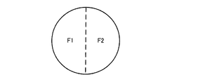
図16は、回転フィルタ702の構成の一例を示している。この回転フィルタはF1、F2色フィルタを備え、均等に2領域に分けられている。F1フィルタは、図4に示しているR+G+Bの透過率特性(400nm〜700nm)に対応し、F2フィルタは、図5に示している所定の狭帯域のB1+G1の透過率特性(G1(530nm〜550nm)、B1(390nm〜445nm))に対応している。通常光光源701からの白色光は、F1フィルタに照射されることにより白色光を形成するのに対し、F2フィルタに照射されることにより特殊光(NBI)を形成することになる。
FIG. 16 shows an example of the configuration of the
本実施例では、発光制御部603の制御に基づき、所定の速度で回転フィルタ702を回転させる。この回転フィルタ702の回転により、通常光光源701からの白色光は、F1−>F2−>F1−>F2−>F1−>F2・・・に順次に照射することで、白色光−>特殊光−>白色光−>特殊光−>白色光−>特殊光−>・・・を形成することになる。形成した白色光と特殊光を順次に集光レンズ703を経由し、ライトガイド103へ転送して被写体100へ照射する。結果的に、所定の時間間隔で白色光と特殊光が順次に繰り返して被写体100へ照射し、その反射光はレンズ201を経由して撮像素子203へ照射する。
In this embodiment, based on the control of the light
本実施例において、撮像素子203は通常光画像を形成するためのベイヤ配列の色フィルタを持つ撮像素子である。撮像素子203は、光電変換により白色光及び特殊光の反射光を順次に繰り返して通常光アナログ画像信号及び特殊光アナログ画像信号へ変換する。変換された通常光アナログ画像信号と特殊アナログ画像信号は順次に繰り返してA/D変換部604へ転送される。
In this embodiment, the
続いて、制御部221の制御に基づき、通常光アナログ画像信号をデジタル化して通常光デジタル画像信号(以下通常光画像信号と略称)として通常光画像取得部213へ転送する。一方、特殊光アナログ画像信号をデジタル化して特殊光デジタル画像信号(以下特殊光画像信号と略称)として特殊光画像取得部605へ転送する。
Subsequently, based on the control of the
特殊光画像取得部605は、制御部221の制御に基づき、特殊光画像信号に対して画像処理を行う。本実施例では、まず、公知のベイヤ補間処理(ベイヤ画像信号から三板画像信号へ変換)、ただし、この場合、特殊光画像信号は所定の狭帯域のB1+G1の(G1(530nm〜550nm)、B1(390nm〜445nm))分光特性を持つ反射光から形成した画像信号のため、補間処理後形成したRGBチャンネル中のRチャンネル画像信号を使わない。そして、式(2)を用いてNBI特殊光画像(NBI疑似カラー画像)を生成する。
The special light
続いて、カラーマネージメント処理、階調変換処理などを行う。処理後のRGB信号からなる特殊光画像信号を特殊光動きベクトル情報算出部606へ転送する。
Subsequently, color management processing, gradation conversion processing, and the like are performed. The special light image signal composed of the processed RGB signals is transferred to the special light motion vector
特殊光動きベクトル情報算出部606は、制御部221の制御に基づき、通常光動きベクトル情報算出部215からの通常光動きベクトルを用いて特殊光動きベクトル情報を算出する。具体的に処理構成は以下のようになっている。本実施例では、所定の均等時間間隔で順次に繰り返して通常光画像信号及び特殊光画像信号を形成するため、通常光画像信号と特殊光画像信号の形成タイミングはずれていることが特徴である。そのため、通常光画像信号からなる通常光動きベクトルを用いて、ずれたタイミングで形成した特殊光画像信号の動きを予測し特殊光動きベクトルの補正量を推定する。例えば、通常光画像信号1−>特殊光画像信号1−>通常光画像信号2−>特殊光画像信号2−>通常光画像信号3・・・の場合、通常光画像信号と特殊光画像信号の形成時間間隔は同じのため、通常光画像信号1、通常光画像信号2および通常光画像信号3から算出した通常光動きベクトルを用いて、式(7)で特殊光画像信号1と特殊光画像信号2の間の特殊光動きベクトルを算出する。
The special light motion vector
u=(U1+U2)/2
v=(V1+V2)/2 ・・・・・(7)
u = (U1 + U2) / 2
v = (V1 + V2) / 2 (7)
ただし、(u,v)は特殊光画像信号1と特殊光画像信号2の特殊光動きベクトル、(U1,V1)は通常光画像信号1と通常光画像信号2の通常光動きベクトル、(U2,V2)は通常光画像信号2と通常光画像信号3の通常光動きベクトルである。
However, (u, v) is a special light motion vector of the special
図17は、特殊光動きベクトル情報算出部606の構成の一つの変形例を示すもので、第3バッファー部501、動きベクトル検出部512、動きベクトル補正部513、RAM504を備えている。特殊光画像取得部605は、動きベクトル検出部512及び動きベクトル補正部513を介して特殊光ノイズ低減部218へ接続している。特殊光画像保存部223は、第3バッファー部501を介して、動きベクトル検出部512へ接続している。通常光動きベクトル情報算出部215は、RAM504を介して動きベクトル補正部513へ接続している。制御部221は、第3バッファー部501、動きベクトル検出部512、動きベクトル補正部513及びRAM504と双方向に接続している。
FIG. 17 shows a modification of the configuration of the special light motion vector
本実施例では、同じ解像度(画像サイズ)をもつ通常光画像信号と特殊光画像信号を処理することを設定する。通常光動きベクトル情報算出部215からの通常光動きベクトル情報をRAM504へ保存する。
In this embodiment, it is set to process a normal light image signal and a special light image signal having the same resolution (image size). The normal light motion vector information from the normal light motion vector
動きベクトル検出部512は、制御部221の制御に基づき、特殊光画像取得部605からの現フレーム特殊光画像信号を用いて特殊光画像保存部223から時間的に一番近い過去フレーム特殊光画像信号に対し、前記通常光画像信号の処理と同様に公知のテンプレートマッチング処理を行い、特殊光動きベクトルを検出する。
The motion
しかし、上述したように、通常光より狭い波長帯域を持つ特殊光で撮影した画像信号は通常光画像に比べて暗いため、ノイズの影響は相対的に大きくなる。従って、特殊光画像信号のみから特殊光動きベクトルを検出した場合、ノイズの影響により、動き検出精度も落ちる可能性がある。 However, as described above, since the image signal captured with the special light having a narrower wavelength band than the normal light is darker than the normal light image, the influence of noise becomes relatively large. Therefore, when the special light motion vector is detected only from the special light image signal, there is a possibility that the motion detection accuracy may be lowered due to the influence of noise.
そこで、動きベクトル補正部513は、通常光動きベクトル情報を用いて、特殊光動きベクトルを補正する。
Therefore, the motion
図18は、動きベクトル補正部513の構成の一例を示すもので、判定部801、動きベクトル更新部802およびRAM803を備えている。動きベクトル検出部512は、判定部801及び動きベクトル更新部802を介して特殊光ノイズ低減部218へ接続している。RAM803およびRAM504は、動きベクトル更新部802へ接続している。制御部221は、判定部801、動きベクトル更新部802およびRAM803と双方向に接続している。
FIG. 18 shows an example of the configuration of the motion
判定部801は、制御部221の制御に基づき、動きベクトル検出部512からの現フレーム特殊光画像信号に対して判定を行う。具体的には、RAM803からの所定の閾値を用いて画素ごとに特殊光画像信号のRch_v画像信号値(図5に示すG1の分光特性をもつ)と大きさで比較する。比較情報、現フレーム特殊光画像信号および特殊光動きベクトル情報を動きベクトル更新部802へ転送する。RAM803中の所定の閾値は、制御部221の制御に基づき、ユーザが外部I/F222を介して指定してもよいし、ユーザが外部I/F222を介して事前に保存されている複数の閾値候補から選択してもよい。
The
動きベクトル更新部802は、制御部221の制御に基づき、判定部801からの閾値比較情報、特殊光動きベクトル情報およびRAM504から通常光動きベクトル情報を用いて、特殊光動きベクトルを補正する。具体的には、現フレーム特殊光画像信号値が閾値より大きい場合、特殊光動きベクトルを補正しない。一方、現フレーム特殊光画像信号値が閾値より小さい場合、前記式(15)により計算した時間的に現フレーム特殊光画像の前後フレームの通常光動きベクトルを特殊光動きベクトルとして入れ替える。そうすることによって、特殊光動き検出に関しては、特殊光画像信号中の明るい領域においては、特殊光動きベクトル情報を用いるのに対し、暗い領域においては、通常光動きベクトルを適用する。これにより、できる限り特殊光画像信号から特殊光動きベクトルを検出することになるため、特殊光動きベクトルの検出精度を高めることが可能となる。
The motion
また、以上の説明では、特殊光動きベクトルとして、特殊光画像から求めた動きベクトル(ここでは(XN,YN)とする)もしくは通常光動きベクトル((XW,YW)とする)のどちらか一方を用いるものとしたが、これに限定されるものではない。特殊光画像から求めた動きベクトルと、通常光動きベクトルとを所定の混合割合で混合して用いてもよい。 In the above description, either the motion vector obtained from the special light image (here, (XN, YN)) or the normal light motion vector ((XW, YW)) is used as the special light motion vector. However, the present invention is not limited to this. The motion vector obtained from the special light image and the normal light motion vector may be mixed and used at a predetermined mixing ratio.
例えば、特殊光画像の画素の明るさ情報について2つの閾値TH1及びTH2(TH1<TH2、つまりTH1が暗くTH2が明るい)を用意しておき、特殊光画像の明るさ情報により表される値がTH1よりも小さい場合には、(XW,YW)を特殊光動きベクトルとして用い、TH2よりも大きい場合には、(XN,YN)を特殊光動きベクトルとして用いる。そして、TH1とTH2の間の値の時には、明るさ情報の値に応じて混合割合αを設定し、下式(8)により特殊光動きベクトル(X,Y)を求めてもよい。 For example, two threshold values TH1 and TH2 (TH1 <TH2, that is, TH1 is dark and TH2 is bright) are prepared for the brightness information of the pixels of the special light image, and a value represented by the brightness information of the special light image is obtained. When it is smaller than TH1, (XW, YW) is used as a special light motion vector, and when it is larger than TH2, (XN, YN) is used as a special light motion vector. When the value is between TH1 and TH2, the mixing ratio α may be set according to the value of the brightness information, and the special light motion vector (X, Y) may be obtained by the following equation (8).
(X,Y)=(XN×(1−α)+XW×α,YN×(1−α)+YW×α)
・・・・・(8)
(X, Y) = (XN × (1−α) + XW × α, YN × (1−α) + YW × α)
(8)
本実施形態においても、第1の実施形態と同様に、画像処理装置をソフトウェア的に実現することが可能である。本実施形態における処理の詳細を示すフローチャートは、第1の実施形態と同様に図12である。 Also in the present embodiment, the image processing apparatus can be realized by software, as in the first embodiment. The flowchart showing the details of the processing in the present embodiment is FIG. 12 as in the first embodiment.
第1の実施形態と同様の処理が行われるステップについては説明を省略し、異なる部分について述べる。まずS1〜S6までのステップは第1の実施形態と同様である。 A description of steps in which processing similar to that of the first embodiment is performed will be omitted, and only different portions will be described. First, the steps from S1 to S6 are the same as those in the first embodiment.
S7にて、通常光動きベクトルを取得する。上述したように(または図2に示したように)、特殊光動きベクトルに相当する動きベクトルを求めるためには、本実施形態においては2つの通常光動きベクトルが必要である。よって、第1の実施形態とは異なり、2つの通常光動きベクトルを取得する。図2に示したように、VB3を求めるためには、VB1とVB2の両方が必要であるため、B5を取得した段階ではVB3を求めることができない。よって厳密には、B6に相当する特殊光画像(図2には不図示)を取得するタイミングで、VB3を取得することになる。 In S7, a normal light motion vector is acquired. As described above (or as shown in FIG. 2), in order to obtain a motion vector corresponding to the special light motion vector, two normal light motion vectors are required in this embodiment. Therefore, unlike the first embodiment, two normal light motion vectors are acquired. As shown in FIG. 2, in order to obtain VB3, both VB1 and VB2 are required. Therefore, VB3 cannot be obtained when B5 is obtained. Therefore, strictly speaking, VB3 is acquired at the timing of acquiring a special light image (not shown in FIG. 2) corresponding to B6.
次にS8にて、特殊光動きベクトルを算出する。S8における処理を図示したものが図19である。図19の処理が開始されると、まず、S21にて、取得した2つの通常光動きベクトルの平均をとることで、特殊光動きベクトルに対応する通常光動きベクトル(XW,YW)を取得する。 Next, in S8, a special light motion vector is calculated. FIG. 19 illustrates the processing in S8. When the processing of FIG. 19 is started, first, in S21, the normal light motion vector (XW, YW) corresponding to the special light motion vector is acquired by averaging the two acquired normal light motion vectors. .
次に、特殊光画像において、過去フレーム特殊光画像信号と、現フレーム特殊光画像信号とのマッチングをとることで、特殊光画像に基づく動きベクトル(XN,YN)を取得する。 Next, in the special light image, the motion vector (XN, YN) based on the special light image is acquired by matching the past frame special light image signal with the current frame special light image signal.
そして、S23にて、特殊光画像の明るさと閾値TH1を比較して、TH1よりも小さい場合には、S25にて、特殊光動きベクトルを(XW,YW)に設定する。TH1以上の場合には、S24にて、特殊光画像の明るさと閾値TH2を比較して、TH2よりも大きい場合には、S26にて、特殊光動きベクトルを(XN,YN)に設定する。 In S23, the brightness of the special light image is compared with the threshold value TH1, and if it is smaller than TH1, the special light motion vector is set to (XW, YW) in S25. If it is greater than TH1, the brightness of the special light image is compared with the threshold value TH2 in S24. If it is greater than TH2, the special light motion vector is set to (XN, YN) in S26.
S24において、TH2以下の場合には、上述した式(8)により、(XW,YW)と(XN,YN)をブレンドしたベクトルを特殊光動きベクトルとする。 In S24, if TH2 or less, a vector obtained by blending (XW, YW) and (XN, YN) is set as the special light motion vector according to the above-described equation (8).
また、第1の実施形態の変形例と同様に、通常光画像の解像度と特殊光画像の解像度が異なる場合には、上述した式(5)、(6)を用いて、(XW,YW)の補正処理が行われる。この補正処理は例えば、S21の後等に行われてもよい。 Similarly to the modification of the first embodiment, when the resolution of the normal light image and the resolution of the special light image are different, the above equations (5) and (6) are used to (XW, YW) The correction process is performed. This correction process may be performed after S21, for example.
特殊光動きベクトルが求められた後のS9の処理は第1の実施形態と同様である。 The processing of S9 after the special light motion vector is obtained is the same as in the first embodiment.
このように、時系列に順次に繰り返して撮像した通常光画像信号と特殊光画像信号を取り扱う画像処理装置において、まず一の特殊光画像信号に対して時系列に前後に位置する通常光動きベクトルを平均化、あるいは通常光動きベクトルと特殊光動きベクトルを混合して撮像タイミングがずれる特殊光画像信号の動きを予測してこの特殊光動きベクトルを推定することが可能となり、その特殊光動きベクトルを用いて特殊光画像信号のノイズ低減効果を高めることができるため、特殊光画像信号での診断能力を向上することにつながる。 In this way, in an image processing apparatus that handles a normal light image signal and a special light image signal that are repeatedly and sequentially imaged in time series, first, a normal light motion vector that is positioned before and after the one special light image signal in time series It is possible to estimate the special light motion vector by predicting the motion of the special light image signal whose imaging timing is shifted by mixing the normal light motion vector and the special light motion vector. Since the noise reduction effect of the special light image signal can be enhanced by using, the diagnostic ability of the special light image signal is improved.
以上の本実施形態では、画像処理装置は、図14に示したように、通常光動きベクトル情報に基づいて特殊光動きベクトル情報を算出する特殊光動きベクトル情報算出部606を含む。そして、ノイズ低減部(図14における特殊光ノイズ低減部218)は、特殊光動きベクトル情報に基づいて、特殊光画像中のノイズ量を低減する。
In the present embodiment described above, the image processing apparatus includes the special light motion vector
これにより、図2に示したように、通常光画像と特殊光画像とが同時に取得されないようなケースにおいても、通常光動きベクトル情報に基づいて特殊光動きベクトル情報を算出することができ、効率的なノイズ低減処理が可能になる。 As a result, as shown in FIG. 2, even in the case where the normal light image and the special light image are not acquired simultaneously, the special light motion vector information can be calculated based on the normal light motion vector information, and the efficiency Noise reduction processing becomes possible.
また、特殊光画像取得部605は、第1のタイミングにおいて第1特殊光画像を取得し、第2のタイミングにおいて第2特殊光画像を取得する。そして、特殊光動きベクトル情報算出部606は、通常光動きベクトル情報に基づいて第1特殊光画像と第2特殊光画像との間の特殊光動きベクトル情報を算出する。そして、ノイズ低減部は、特殊光動きベクトル情報を用いて、第1特殊光画像又は第2特殊光画像中のノイズ量を低減してもよい。
The special light
これにより、タイミング(フレーム)の異なる特殊光画像間の特殊光動きベクトル情報を算出することが可能になる。具体的には例えば図2に示すような、B4とB5の間の特殊光動きベクトル情報VB3を求めることに相当する。 This makes it possible to calculate special light motion vector information between special light images with different timings (frames). Specifically, for example, this corresponds to obtaining special light motion vector information VB3 between B4 and B5 as shown in FIG.
また、通常光画像取得部213は、複数の通常光画像を時系列的に取得し、特殊光画像取得部605は、複数の特殊光画像を時系列的に取得する。そして、通常光動きベクトル情報算出部215は、複数の特殊光画像のうちの第k(kは自然数)の特殊光画像に対して時系列的に前後の通常光画像に基づいて、第1の通常光動きベクトル情報を求める。それとともに、第k+1の特殊光画像に対して時系列的に前後の通常光画像に基づいて、第2の通常光動きベクトル情報を求める。さらに、特殊光動きベクトル情報算出部606は、第1の通常光動きベクトル情報と第2の通常光動きベクトル情報とに基づいて、第kの特殊光画像と第k+1の特殊光画像の間の特殊光動きベクトル情報を算出してもよい。
Further, the normal light
これにより、図2に示したように、通常光画像と特殊光画像とが同時に取得されないようなケースにおいては、特殊光動きベクトル情報を算出したい複数(ここでは2つ)の特殊光画像のそれぞれに対して、時系列的に前後の通常光画像を用いて通常光動きベクトル情報を算出する。そして、算出した通常光動きベクトル情報を利用することで、特殊光動きベクトル情報を算出することが可能になる。図2の例で言えば、B4の前後であるB1及びB2から通常光動きベクトル情報VB1が求められる。このとき、VB1の前半部分は求めるべき特殊光動きベクトル情報には関係しないが、VB1の後半部分は、特殊光動きベクトル情報と重複する部分である。同様に、B5の前後であるB2及びB3から求められるVB2の前半部分は、求めるべき特殊光動きベクトル情報と重複する。この重複部分を用いることで、特殊光動きベクトル情報を推測することが可能となる。 Thereby, as shown in FIG. 2, in the case where the normal light image and the special light image are not acquired simultaneously, each of a plurality of (here, two) special light images for which special light motion vector information is to be calculated. On the other hand, the normal light motion vector information is calculated using the normal light images before and after in time series. Then, the special light motion vector information can be calculated by using the calculated normal light motion vector information. In the example of FIG. 2, the normal light motion vector information VB1 is obtained from B1 and B2 before and after B4. At this time, the first half of VB1 is not related to the special light motion vector information to be obtained, but the second half of VB1 is a portion overlapping with the special light motion vector information. Similarly, the first half of VB2 obtained from B2 and B3 before and after B5 overlaps with the special light motion vector information to be obtained. By using this overlapping portion, it is possible to estimate special light motion vector information.
具体的には、第kの特殊光画像に対して時系列的に前後の通常光画像とは、第p(pは自然数)の通常光画像と第p+1の通常光画像であってもよく、第k+1の特殊光画像に対して時系列的に前後の通常光画像とは、第q(qは自然数)の通常光画像と第q+1の通常光画像であってもよい。ここで、第pの通常光画像と第p+1の通常光画像は、第kの特殊光画像の直前、直後の通常光画像であってもよいし、そうでなくてもよい。同様に、第qの通常光画像と第q+1の通常光画像は、第k+1の特殊光画像の直前、直後の通常光画像であってもよいし、そうでなくてもよい。 Specifically, the normal light images before and after the k-th special light image in time series may be a p-th (p is a natural number) normal light image and a (p + 1) -th normal light image. The normal light images before and after the k + 1th special light image in time series may be the qth (q is a natural number) normal light image and the q + 1th normal light image. Here, the p-th normal light image and the p + 1-th normal light image may or may not be normal light images immediately before and immediately after the k-th special light image. Similarly, the q-th normal light image and the q + 1-th normal light image may or may not be normal light images immediately before and after the k + 1-th special light image.
ここで、第p、p+1の通常光画像が第kの特殊光画像の直前、直後であり、かつ、第q、q+1の通常光画像が第k+1の特殊光画像の直前、直後であるという条件を満たし、さらにp+1=qの場合が、図2に示したケースであり、本実施形態で例示した構成に相当する。つまり、通常光画像と特殊光画像が1枚ずつ交互に取得される。このような場合には、特殊光動きベクトル情報算出部606は、第1の通常光動きベクトル情報と第2の通常光動きベクトル情報の平均を求めることで、第kの特殊光画像と、第k+1の特殊光画像の間の特殊光動きベクトル情報を算出することができる。これは、図2に示したように、VB1の後半部分と、VB2の前半部分をあわせたものがVB3に等しいことから、明らかである。
Here, the p and p + 1 ordinary light images are immediately before and immediately after the kth special light image, and the q and q + 1 ordinary light images are immediately before and immediately after the k + 1 special light image. 2 and p + 1 = q is the case shown in FIG. 2, which corresponds to the configuration exemplified in this embodiment. That is, the normal light image and the special light image are alternately acquired one by one. In such a case, the special light motion vector
以上、本発明を適用した2つの実施の形態1〜2およびその変形例について説明したが、本発明は、各実施の形態1〜2やその変形例そのままに限定されるものではなく、実施段階では、発明の要旨を逸脱しない範囲内で構成要素を変形して具体化することができる。また、上記した各実施の形態1〜2や変形例に開示されている複数の構成要素を適宜組み合わせることによって、種々の発明を形成することができる。例えば、各実施の形態1〜2や変形例に記載した全構成要素からいくつかの構成要素を削除してもよい。さらに、異なる実施の形態や変形例で説明した構成要素を適宜組み合わせてもよい。このように、発明の主旨を逸脱しない範囲内において種々の変形や応用が可能である。
The two
100 被写体、101 通常光光源、102 挿入部、103 ライトガイド、
201 レンズ、202 ハーフミラー、203 通常光撮像素子、204 フィルタ、
205 特殊光撮像素子、211 通常光画像A/D変換部、
212 特殊光画像A/D変換部、213 通常光画像取得部、
214 特殊光画像取得部、215 通常光動きベクトル情報算出部、
216 特殊光動きベクトル情報算出部、217 通常光ノイズ低減部、
218 特殊光ノイズ低減部、219 出力部、221 制御部、
222 通常光画像保存部、223 特殊光画像保存部、301 第1バッファー部、
302 第2バッファー部、303 分割部、304 類似度検出部、
501 第3バッファー部、502 補正係数算出部、503 補正部、
512 動きベクトル検出部、513 動きベクトル補正部、601 光源部、
603 発光制御部、604 A/D変換部、605 特殊光画像取得部、
606 特殊光動きベクトル情報算出部、701 通常光光源、702 回転フィルタ、
703 集光レンズ、801 判定部、802 動きベクトル更新部、803 RAM
100 subject, 101 normal light source, 102 insertion section, 103 light guide,
201 lens, 202 half mirror, 203 normal optical image sensor, 204 filter,
205 Special optical image sensor, 211 Normal light image A / D converter,
212 special light image A / D conversion unit, 213 normal light image acquisition unit,
214 special light image acquisition unit, 215 normal light motion vector information calculation unit,
216 special light motion vector information calculation unit, 217 normal light noise reduction unit,
218 special light noise reduction unit, 219 output unit, 221 control unit,
222 normal light image storage unit, 223 special light image storage unit, 301 first buffer unit,
302 second buffer unit, 303 dividing unit, 304 similarity detection unit,
501 third buffer unit, 502 correction coefficient calculation unit, 503 correction unit,
512 motion vector detection unit, 513 motion vector correction unit, 601 light source unit,
603 light emission control unit, 604 A / D conversion unit, 605 special light image acquisition unit,
606 special light motion vector information calculation unit, 701 normal light source, 702 rotation filter,
703 Condensing lens, 801 determination unit, 802 motion vector update unit, 803 RAM
Claims (19)
特定の波長帯域における情報を含む画像を特殊光画像として取得する特殊光画像取得部と、
前記通常光画像内の特徴量に基づいて、複数の通常光画像間の動きベクトルを示す通常光動きベクトル情報を算出する通常光動きベクトル情報算出部と、
前記通常光画像の解像度と前記特殊光画像の解像度との比較結果に基づいて、算出された前記通常光動きベクトル情報を補正する補正部と、
補正された前記通常光動きベクトル情報に基づいて、前記特殊光画像間の動きベクトルを示す特殊光動きベクトル情報を算出する特殊光動きベクトル情報算出部と、
前記特殊光動きベクトル情報に基づいて、前記特殊光画像中のノイズ量を低減するノイズ低減部と、
を含むことを特徴とする画像処理装置。 A normal light image acquisition unit that acquires an image including information in the wavelength band of white light as a normal light image;
A special light image acquisition unit that acquires an image including information in a specific wavelength band as a special light image;
A normal light motion vector information calculation unit that calculates normal light motion vector information indicating a motion vector between a plurality of normal light images based on the feature amount in the normal light image;
A correction unit that corrects the calculated normal light motion vector information based on a comparison result between the resolution of the normal light image and the resolution of the special light image;
A special light motion vector information calculating unit that calculates special light motion vector information indicating a motion vector between the special light images based on the corrected normal light motion vector information;
A noise reduction unit that reduces the amount of noise in the special light image based on the special light motion vector information ;
An image processing apparatus comprising:
前記通常光画像取得部は、
第1のタイミングにおいて第1通常光画像を取得するとともに、第2のタイミングにおいて第2通常光画像を取得し、
前記通常光動きベクトル情報算出部は、
前記第1通常光画像内の特徴量と、前記第2通常光画像内の特徴量とに基づいて、前記第1通常光画像と前記第2通常光画像間の前記通常光動きベクトル情報を算出することを特徴とする画像処理装置。 In claim 1,
The normal light image acquisition unit
Acquiring a first normal light image at a first timing and acquiring a second normal light image at a second timing;
The normal light motion vector information calculation unit includes:
Based on the feature amount in the first normal light image and the feature amount in the second normal light image, the normal light motion vector information between the first normal light image and the second normal light image is calculated. An image processing apparatus.
前記通常光動きベクトル情報算出部は、
前記第1通常光画像内の特徴量と、前記第2通常光画像内の特徴量とを用いてマッチング処理を行うことで、前記通常光動きベクトル情報を算出することを特徴とする画像処理装置。 In claim 2,
The normal light motion vector information calculation unit includes:
An image processing apparatus that calculates the normal light motion vector information by performing a matching process using a feature amount in the first normal light image and a feature amount in the second normal light image. .
前記補正部は、
前記通常光画像の解像度と前記特殊光画像の解像度との比較結果により特定される、前記通常光動きベクトル情報の拡大率又は縮小率を、算出された前記通常光動きベクトル情報に対して乗算することで、前記通常光動きベクトル情報を補正することを特徴とする画像処理装置。 In claim 1 ,
The correction unit is
The calculated normal light motion vector information is multiplied by the enlargement ratio or the reduction ratio of the normal light motion vector information specified by the comparison result between the resolution of the normal light image and the resolution of the special light image. Thus, the normal light motion vector information is corrected.
前記通常光画像取得部は、
前記通常光画像として、複数の通常光画像を時系列的に取得し、
前記特殊光画像取得部は、
前記特殊光画像として、複数の特殊光画像を時系列的に取得し、
前記通常光動きベクトル情報算出部は、
前記複数の特殊光画像のうちの第k(kは自然数)の特殊光画像に対して時系列的に前後の複数の通常光画像に基づいて、第1の通常光動きベクトル情報を求めるとともに、第k+1の特殊光画像に対して時系列的に前後の複数の通常光画像に基づいて、第2の通常光動きベクトル情報を求め、
前記特殊光動きベクトル情報算出部は、
前記第1の通常光動きベクトル情報と前記第2の通常光動きベクトル情報とに基づいて、前記第kの特殊光画像と前記第k+1の特殊光画像との間の特殊光動きベクトル情報を算出することを特徴とする画像処理装置。 In claim 1,
The normal light image acquisition unit
As the normal light image, a plurality of normal light images are acquired in time series,
The special light image acquisition unit
As the special light image, a plurality of special light images are acquired in time series,
The normal light motion vector information calculation unit includes:
Obtaining first normal light motion vector information based on a plurality of normal light images before and after the kth (k is a natural number) special light image of the plurality of special light images in time series; Obtaining second normal light motion vector information based on a plurality of normal light images before and after the k + 1th special light image in time series;
The special light motion vector information calculation unit includes:
Based on the first normal light motion vector information and the second normal light motion vector information, special light motion vector information between the kth special light image and the k + 1th special light image is calculated. An image processing apparatus.
前記通常光動きベクトル情報算出部は、
前記複数の特殊光画像のうちの第k(kは自然数)の特殊光画像に対して時系列的に前である第p(pは自然数)の通常光画像と、時系列的に後である第p+1の通常光画像とに基づいて、前記第1の通常光動きベクトル情報を求めるとともに、第k+1の特殊光画像に対して時系列的に前である第q(qは自然数)の通常光画像と、時系列的に後である第q+1の通常光画像とに基づいて、前記第2の通常光動きベクトル情報を求め、
前記特殊光動きベクトル情報算出部は、
前記第1の通常光動きベクトル情報と前記第2の通常光動きベクトル情報とに基づいて、前記第kの特殊光画像と前記第k+1の特殊光画像との間の特殊光動きベクトル情報を算出することを特徴とする画像処理装置。 In claim 5 ,
The normal light motion vector information calculation unit includes:
Of the plurality of special light images, the p-th (p is a natural number) normal light image that is chronologically preceding and chronologically later than the kth (k is a natural number) special light image. The first normal light motion vector information is obtained based on the (p + 1) th normal light image, and the qth (q is a natural number) normal light that is chronologically preceding the k + 1th special light image. Obtaining the second normal light motion vector information based on the image and the q + 1th normal light image later in time series,
The special light motion vector information calculation unit includes:
Based on the first normal light motion vector information and the second normal light motion vector information, special light motion vector information between the kth special light image and the k + 1th special light image is calculated. An image processing apparatus.
前記特殊光動きベクトル情報算出部は、
前記第1の通常光動きベクトル情報と、前記第2の通常光動きベクトル情報とを平均した動きベクトル情報を、前記第kの特殊光画像と前記第k+1の特殊光画像との間の前記特殊光動きベクトル情報として算出することを特徴とする画像処理装置。 In claim 5 ,
The special light motion vector information calculation unit includes:
The motion vector information obtained by averaging the first normal light motion vector information and the second normal light motion vector information is used as the special vector between the kth special light image and the k + 1th special light image. An image processing apparatus characterized by calculating as light motion vector information.
前記特殊光画像取得部は、
第1のタイミングにおいて第1特殊光画像を取得するとともに、第2のタイミングにおいて第2特殊光画像を取得し、
前記ノイズ低減部は、
前記通常光動きベクトル情報に基づいて、前記第1特殊光画像内の第1の処理対象領域に対応する領域である第2の処理対象領域を前記第2特殊光画像内において設定し、
前記第1の処理対象領域の特徴量と前記第2の処理対象領域の特徴量に基づいて、前記第1の処理対象領域または前記第2の処理対象領域中のノイズ量を低減することを特徴とする画像処理装置。 In claim 1,
The special light image acquisition unit
Obtaining a first special light image at a first timing and obtaining a second special light image at a second timing;
The noise reduction unit is
Based on the normal light motion vector information, a second processing target region that is a region corresponding to the first processing target region in the first special light image is set in the second special light image;
A noise amount in the first processing target region or the second processing target region is reduced based on a feature amount of the first processing target region and a feature amount of the second processing target region. An image processing apparatus.
前記ノイズ低減部は、
前記第1の処理対象領域の特徴量と前記第2の処理対象領域の特徴量との差分量に基づいて、前記第2の処理対象領域中に含まれるべき第2ノイズ量を推定するノイズ量推定部を含み、
前記ノイズ低減部は、
前記ノイズ量推定部が推定した前記第2ノイズ量と、前記第2の処理対象領域の特徴量との差分を求めることで、前記第2の処理対象領域中のノイズ量を低減することを特徴とする画像処理装置。 In claim 8 ,
The noise reduction unit is
A noise amount for estimating a second noise amount to be included in the second processing target region based on a difference amount between the feature amount of the first processing target region and the feature amount of the second processing target region Including an estimator,
The noise reduction unit is
The noise amount in the second processing target region is reduced by obtaining a difference between the second noise amount estimated by the noise amount estimation unit and the feature amount of the second processing target region. An image processing apparatus.
前記ノイズ量推定部は、
第1の処理対象領域の特徴量と第2の処理対象領域の特徴量との差分量と、推定すべきノイズ量との対応関係情報を取得し、取得した前記対応関係情報に基づいて、前記第2のノイズ量を推定することを特徴とする画像処理装置。 In claim 9 ,
The noise amount estimation unit
Obtaining correspondence information between the difference amount between the feature amount of the first processing target region and the feature amount of the second processing target region and the noise amount to be estimated, and based on the obtained correspondence relationship information, An image processing apparatus that estimates a second noise amount.
前記ノイズ低減部は、
前記第1の処理対象領域の特徴量と前記第2の処理対象領域の特徴量との差をゼロに近づける制御をすることで、前記第1の処理対象領域または前記第2の処理対象領域中のノイズ量を低減することを特徴とする画像処理装置。 In claim 8 ,
The noise reduction unit is
By controlling the difference between the feature amount of the first processing target region and the feature amount of the second processing target region to be close to zero, the first processing target region or the second processing target region An image processing apparatus that reduces the amount of noise.
前記特定の波長帯域は、
前記白色光の波長帯域よりも狭い帯域であることを特徴とする画像処理装置。 In claim 1,
The specific wavelength band is
An image processing apparatus having a band narrower than a wavelength band of the white light.
前記通常光画像および前記特殊光画像は生体内を写した生体内画像であり、
前記生体内画像に含まれる前記特定の波長帯域は、血液中のヘモグロビンに吸収される波長の波長帯域であることを特徴とする画像処理装置。 In claim 12 ,
The normal light image and the special light image are in-vivo images obtained by copying the inside of the living body,
The image processing apparatus according to claim 1, wherein the specific wavelength band included in the in-vivo image is a wavelength band of a wavelength absorbed by hemoglobin in blood.
前記波長帯域は、390ナノメータ〜445ナノメータ、または530ナノメータ〜550ナノメータであることを特徴とする画像処理装置。 In claim 13 ,
The image processing apparatus according to claim 1, wherein the wavelength band is 390 nanometers to 445 nanometers, or 530 nanometers to 550 nanometers.
前記通常光画像および前記特殊光画像は生体内を写した生体内画像であり、
前記生体内画像に含まれる前記特定の波長帯域は、蛍光物質が発する蛍光の波長帯域であることを特徴とする画像処理装置。 In claim 1,
The normal light image and the special light image are in-vivo images obtained by copying the inside of the living body,
The image processing apparatus according to claim 1, wherein the specific wavelength band included in the in-vivo image is a wavelength band of fluorescence emitted from a fluorescent material.
前記特定の波長帯域は、490ナノメータ〜625ナノメータの波長帯域であることを特徴とする画像処理装置。 In claim 15 ,
The image processing apparatus according to claim 1, wherein the specific wavelength band is a wavelength band of 490 nanometers to 625 nanometers.
前記通常光画像および前記特殊光画像は生体内を写した生体内画像であり、
前記生体内画像に含まれる前記特定の波長帯域は、赤外光の波長帯域であることを特徴とする画像処理装置。 In claim 1,
The normal light image and the special light image are in-vivo images obtained by copying the inside of the living body,
The image processing apparatus, wherein the specific wavelength band included in the in-vivo image is a wavelength band of infrared light.
前記波長帯域は、790ナノメータ〜820ナノメータ、または905ナノメータ〜970ナノメータの波長帯域であることを特徴とする画像処理装置。 In claim 17 ,
The image processing apparatus according to claim 1, wherein the wavelength band is a wavelength band of 790 nanometers to 820 nanometers, or 905 nanometers to 970 nanometers.
特定の波長帯域における情報を含む画像を特殊光画像として取得する特殊光画像取得部と、
前記通常光画像内の特徴量に基づいて、複数の通常光画像間の動きベクトルを示す通常光動きベクトル情報を算出する通常光動きベクトル情報算出部と、
前記通常光画像の解像度と前記特殊光画像の解像度との比較結果に基づいて、算出された前記通常光動きベクトル情報を補正する補正部と、
補正された前記通常光動きベクトル情報に基づいて、前記特殊光画像間の動きベクトルを示す特殊光動きベクトル情報を算出する特殊光動きベクトル情報算出部と、
前記特殊光動きベクトル情報に基づいて、前記特殊光画像中のノイズ量を低減するノイズ低減部として、
コンピュータを機能させることを特徴とするプログラム。 A normal light image acquisition unit that acquires an image including information in the wavelength band of white light as a normal light image;
A special light image acquisition unit that acquires an image including information in a specific wavelength band as a special light image;
A normal light motion vector information calculation unit that calculates normal light motion vector information indicating a motion vector between a plurality of normal light images based on the feature amount in the normal light image;
A correction unit that corrects the calculated normal light motion vector information based on a comparison result between the resolution of the normal light image and the resolution of the special light image;
A special light motion vector information calculating unit that calculates special light motion vector information indicating a motion vector between the special light images based on the corrected normal light motion vector information;
As a noise reduction unit that reduces the amount of noise in the special light image based on the special light motion vector information ,
A program characterized by causing a computer to function.
Priority Applications (3)
| Application Number | Priority Date | Filing Date | Title |
|---|---|---|---|
| JP2010147197A JP5603676B2 (en) | 2010-06-29 | 2010-06-29 | Image processing apparatus and program |
| CN201110177083.8A CN102316247B (en) | 2010-06-29 | 2011-06-28 | Image processing apparatus |
| US13/171,741 US8711252B2 (en) | 2010-06-29 | 2011-06-29 | Image processing device and information storage medium including motion vector information calculation |
Applications Claiming Priority (1)
| Application Number | Priority Date | Filing Date | Title |
|---|---|---|---|
| JP2010147197A JP5603676B2 (en) | 2010-06-29 | 2010-06-29 | Image processing apparatus and program |
Publications (3)
| Publication Number | Publication Date |
|---|---|
| JP2012010730A JP2012010730A (en) | 2012-01-19 |
| JP2012010730A5 JP2012010730A5 (en) | 2013-08-08 |
| JP5603676B2 true JP5603676B2 (en) | 2014-10-08 |
Family
ID=45352203
Family Applications (1)
| Application Number | Title | Priority Date | Filing Date |
|---|---|---|---|
| JP2010147197A Active JP5603676B2 (en) | 2010-06-29 | 2010-06-29 | Image processing apparatus and program |
Country Status (3)
| Country | Link |
|---|---|
| US (1) | US8711252B2 (en) |
| JP (1) | JP5603676B2 (en) |
| CN (1) | CN102316247B (en) |
Cited By (1)
| Publication number | Priority date | Publication date | Assignee | Title |
|---|---|---|---|---|
| WO2020050187A1 (en) * | 2018-09-06 | 2020-03-12 | ソニー株式会社 | Medical system, information processing device, and information processing method |
Families Citing this family (21)
| Publication number | Priority date | Publication date | Assignee | Title |
|---|---|---|---|---|
| JP5507376B2 (en) * | 2010-07-28 | 2014-05-28 | 三洋電機株式会社 | Imaging device |
| US9332239B2 (en) * | 2012-05-31 | 2016-05-03 | Apple Inc. | Systems and methods for RGB image processing |
| JP6041561B2 (en) * | 2012-07-19 | 2016-12-07 | キヤノン株式会社 | Image processing apparatus and control method thereof |
| US8717457B2 (en) * | 2012-08-14 | 2014-05-06 | Canon Kabushiki Kaisha | Adaptive spectral imaging for video capture |
| JP6112291B2 (en) * | 2012-12-11 | 2017-04-12 | パナソニックIpマネジメント株式会社 | Diagnosis support apparatus and diagnosis support method |
| JP6230409B2 (en) * | 2013-12-20 | 2017-11-15 | オリンパス株式会社 | Endoscope device |
| JP2015171450A (en) * | 2014-03-12 | 2015-10-01 | ソニー株式会社 | Image processing device, image processing method, program, and endoscope apparatus |
| US20150346115A1 (en) * | 2014-05-30 | 2015-12-03 | Eric J. Seibel | 3d optical metrology of internal surfaces |
| CN105160628B (en) * | 2015-09-07 | 2018-09-14 | 努比亚技术有限公司 | A kind of method and apparatus obtaining RGB data |
| JP6556076B2 (en) * | 2016-03-10 | 2019-08-07 | 富士フイルム株式会社 | Endoscopic image signal processing apparatus and method, and program |
| JP6522539B2 (en) * | 2016-03-18 | 2019-05-29 | 富士フイルム株式会社 | Endoscope system and method of operating the same |
| WO2018016002A1 (en) * | 2016-07-19 | 2018-01-25 | オリンパス株式会社 | Image processing device, endoscope system, program, and image processing method |
| JP6581952B2 (en) * | 2016-09-30 | 2019-09-25 | 富士フイルム株式会社 | Endoscope system and operating method thereof |
| WO2018180631A1 (en) * | 2017-03-30 | 2018-10-04 | 富士フイルム株式会社 | Medical image processing device, endoscope system, and method for operating medical image processing device |
| JP2019136269A (en) * | 2018-02-09 | 2019-08-22 | 株式会社島津製作所 | Fluorescent imaging device |
| JP7068438B2 (en) * | 2018-03-13 | 2022-05-16 | オリンパス株式会社 | Image processing equipment, endoscope systems, image processing methods and programs |
| WO2020203164A1 (en) * | 2019-03-29 | 2020-10-08 | ソニー株式会社 | Medical system, information processing device, and information processing method |
| CN110334331A (en) * | 2019-05-30 | 2019-10-15 | 重庆金融资产交易所有限责任公司 | Method, apparatus and computer equipment based on order models screening table |
| CN110866883B (en) * | 2019-11-29 | 2023-03-17 | 上海联影医疗科技股份有限公司 | Dual-energy CT image denoising method, device, terminal and storage medium |
| JP2021196656A (en) * | 2020-06-09 | 2021-12-27 | キヤノン株式会社 | Processing device, processing system, photographing device, processing method, and program |
| CN116269155B (en) * | 2023-03-22 | 2024-03-22 | 新光维医疗科技(苏州)股份有限公司 | Image diagnosis method, image diagnosis device, and image diagnosis program |
Family Cites Families (25)
| Publication number | Priority date | Publication date | Assignee | Title |
|---|---|---|---|---|
| JPH01212077A (en) * | 1986-12-26 | 1989-08-25 | Olympus Optical Co Ltd | Signal processing circuit for electronic endoscope |
| KR930006669B1 (en) * | 1991-07-08 | 1993-07-22 | 삼성전자 주식회사 | Motion adaptive noise reducer for tv image system |
| JPH07193791A (en) * | 1993-12-25 | 1995-07-28 | Sony Corp | Picture information converter |
| JPH07246184A (en) * | 1994-03-09 | 1995-09-26 | Fuji Photo Optical Co Ltd | Frame sequential imaging device |
| US6448545B1 (en) * | 2000-01-18 | 2002-09-10 | Syncrotronics Corp. | Precision endoscopic imaging system |
| US6826424B1 (en) * | 2000-12-19 | 2004-11-30 | Haishan Zeng | Methods and apparatus for fluorescence and reflectance imaging and spectroscopy and for contemporaneous measurements of electromagnetic radiation with multiple measuring devices |
| JP4343594B2 (en) * | 2003-06-23 | 2009-10-14 | オリンパス株式会社 | Endoscope device |
| JP4294440B2 (en) * | 2003-10-30 | 2009-07-15 | オリンパス株式会社 | Image processing device |
| KR100994768B1 (en) * | 2003-12-08 | 2010-11-16 | 삼성전자주식회사 | Motion estimation method for encoding motion image, and recording medium storing a program to implement thereof |
| US7901348B2 (en) * | 2003-12-12 | 2011-03-08 | University Of Washington | Catheterscope 3D guidance and interface system |
| US7346109B2 (en) * | 2003-12-23 | 2008-03-18 | Genesis Microchip Inc. | Motion vector computation for video sequences |
| CN1282132C (en) * | 2004-05-20 | 2006-10-25 | 上海交通大学 | Infra-red and visible light dynamic image interfusion method based on moving target detection |
| CN1768715A (en) * | 2004-11-01 | 2006-05-10 | 中国科学院福建物质结构研究所 | Laser therapeutic machine |
| JP5114024B2 (en) * | 2005-08-31 | 2013-01-09 | オリンパス株式会社 | Optical imaging device |
| JP4814667B2 (en) * | 2006-03-24 | 2011-11-16 | Hoya株式会社 | Electronic endoscope device |
| JP4857916B2 (en) * | 2006-06-06 | 2012-01-18 | ソニー株式会社 | Noise suppression method, noise suppression method program, recording medium recording noise suppression method program, and noise suppression device |
| US20110169960A1 (en) * | 2006-11-13 | 2011-07-14 | Redshift Systems Corporation | Video enhancement system |
| JP2008229024A (en) * | 2007-03-20 | 2008-10-02 | Olympus Corp | Fluorescence observation device |
| JP5038027B2 (en) * | 2007-06-13 | 2012-10-03 | オリンパス株式会社 | Image processing apparatus and endoscope apparatus provided with the same |
| JP5329177B2 (en) * | 2007-11-07 | 2013-10-30 | 富士フイルム株式会社 | Imaging system and program |
| JP5052301B2 (en) * | 2007-11-21 | 2012-10-17 | オリンパス株式会社 | Image processing apparatus and image processing method |
| KR101442153B1 (en) * | 2008-01-15 | 2014-09-25 | 삼성전자 주식회사 | Method and system for processing for low light level image. |
| JP2009290827A (en) * | 2008-06-02 | 2009-12-10 | Sony Corp | Image processing apparatus, and image processing method |
| JP5250342B2 (en) * | 2008-08-26 | 2013-07-31 | 富士フイルム株式会社 | Image processing apparatus and program |
| JP5545612B2 (en) * | 2009-01-14 | 2014-07-09 | 富士フイルム株式会社 | Image processing system, image processing method, and program |
-
2010
- 2010-06-29 JP JP2010147197A patent/JP5603676B2/en active Active
-
2011
- 2011-06-28 CN CN201110177083.8A patent/CN102316247B/en active Active
- 2011-06-29 US US13/171,741 patent/US8711252B2/en active Active
Cited By (1)
| Publication number | Priority date | Publication date | Assignee | Title |
|---|---|---|---|---|
| WO2020050187A1 (en) * | 2018-09-06 | 2020-03-12 | ソニー株式会社 | Medical system, information processing device, and information processing method |
Also Published As
| Publication number | Publication date |
|---|---|
| CN102316247A (en) | 2012-01-11 |
| US20110317043A1 (en) | 2011-12-29 |
| JP2012010730A (en) | 2012-01-19 |
| US8711252B2 (en) | 2014-04-29 |
| CN102316247B (en) | 2016-08-17 |
Similar Documents
| Publication | Publication Date | Title |
|---|---|---|
| JP5603676B2 (en) | Image processing apparatus and program | |
| US9154745B2 (en) | Endscope apparatus and program | |
| US9629525B2 (en) | Image processing device, image processing method, and program | |
| JP5864880B2 (en) | Endoscope apparatus and method for operating endoscope apparatus | |
| US8681208B2 (en) | Image processing device and program | |
| JP5541914B2 (en) | Image processing apparatus, electronic apparatus, program, and operation method of endoscope apparatus | |
| US20150294463A1 (en) | Image processing device, endoscope apparatus, image processing method, and information storage device | |
| US20140046131A1 (en) | Endoscope system and method for operating endoscope system | |
| JP5462084B2 (en) | Image processing apparatus and program | |
| US20120241620A1 (en) | Optical control device, control device, and optical scope | |
| JP2011234844A (en) | Controller, endoscope system, and program | |
| WO2016136700A1 (en) | Image processing device | |
| Suman et al. | Image enhancement using geometric mean filter and gamma correction for WCE images | |
| US9826884B2 (en) | Image processing device for correcting captured image based on extracted irregularity information and enhancement level, information storage device, and image processing method | |
| JP2012005512A (en) | Image processor, endoscope apparatus, endoscope system, program, and image processing method | |
| JP6150554B2 (en) | Image processing apparatus, endoscope apparatus, operation method of image processing apparatus, and image processing program | |
| US20150363929A1 (en) | Endoscope apparatus, image processing method, and information storage device | |
| JP6377171B2 (en) | Image processing apparatus, endoscope apparatus, and image processing method | |
| JP5038027B2 (en) | Image processing apparatus and endoscope apparatus provided with the same | |
| US9323978B2 (en) | Image processing device, endoscope apparatus, and image processing method | |
| JP6242230B2 (en) | Image processing apparatus, endoscope apparatus, operation method of image processing apparatus, and image processing program | |
| JP6585623B2 (en) | Biological information measuring device, biological information measuring method, and biological information measuring program | |
| WO2019003285A1 (en) | Image processing device, image processing method, and program | |
| US20150003700A1 (en) | Image processing device, endoscope apparatus, and image processing method | |
| JP2022090759A (en) | Medical image processing system and operation method of medical image processing system |
Legal Events
| Date | Code | Title | Description |
|---|---|---|---|
| A621 | Written request for application examination |
Free format text: JAPANESE INTERMEDIATE CODE: A621 Effective date: 20130502 |
|
| A521 | Request for written amendment filed |
Free format text: JAPANESE INTERMEDIATE CODE: A523 Effective date: 20130621 |
|
| A977 | Report on retrieval |
Free format text: JAPANESE INTERMEDIATE CODE: A971007 Effective date: 20131031 |
|
| A131 | Notification of reasons for refusal |
Free format text: JAPANESE INTERMEDIATE CODE: A131 Effective date: 20131126 |
|
| A521 | Request for written amendment filed |
Free format text: JAPANESE INTERMEDIATE CODE: A523 Effective date: 20140120 |
|
| TRDD | Decision of grant or rejection written | ||
| A01 | Written decision to grant a patent or to grant a registration (utility model) |
Free format text: JAPANESE INTERMEDIATE CODE: A01 Effective date: 20140812 |
|
| A61 | First payment of annual fees (during grant procedure) |
Free format text: JAPANESE INTERMEDIATE CODE: A61 Effective date: 20140822 |
|
| R151 | Written notification of patent or utility model registration |
Ref document number: 5603676 Country of ref document: JP Free format text: JAPANESE INTERMEDIATE CODE: R151 |
|
| S531 | Written request for registration of change of domicile |
Free format text: JAPANESE INTERMEDIATE CODE: R313531 |
|
| R350 | Written notification of registration of transfer |
Free format text: JAPANESE INTERMEDIATE CODE: R350 |
|
| R250 | Receipt of annual fees |
Free format text: JAPANESE INTERMEDIATE CODE: R250 |
|
| R250 | Receipt of annual fees |
Free format text: JAPANESE INTERMEDIATE CODE: R250 |
|
| R250 | Receipt of annual fees |
Free format text: JAPANESE INTERMEDIATE CODE: R250 |
|
| R250 | Receipt of annual fees |
Free format text: JAPANESE INTERMEDIATE CODE: R250 |
|
| R250 | Receipt of annual fees |
Free format text: JAPANESE INTERMEDIATE CODE: R250 |