EP3085187B1 - Enhanced random access procedure for air-to-ground communications - Google Patents
Enhanced random access procedure for air-to-ground communications Download PDFInfo
- Publication number
- EP3085187B1 EP3085187B1 EP14816548.3A EP14816548A EP3085187B1 EP 3085187 B1 EP3085187 B1 EP 3085187B1 EP 14816548 A EP14816548 A EP 14816548A EP 3085187 B1 EP3085187 B1 EP 3085187B1
- Authority
- EP
- European Patent Office
- Prior art keywords
- ground station
- location
- message
- module
- timing offset
- Prior art date
- Legal status (The legal status is an assumption and is not a legal conclusion. Google has not performed a legal analysis and makes no representation as to the accuracy of the status listed.)
- Active
Links
Images


Classifications
-
- H—ELECTRICITY
- H04—ELECTRIC COMMUNICATION TECHNIQUE
- H04W—WIRELESS COMMUNICATION NETWORKS
- H04W56/00—Synchronisation arrangements
- H04W56/004—Synchronisation arrangements compensating for timing error of reception due to propagation delay
-
- H—ELECTRICITY
- H04—ELECTRIC COMMUNICATION TECHNIQUE
- H04B—TRANSMISSION
- H04B7/00—Radio transmission systems, i.e. using radiation field
- H04B7/14—Relay systems
- H04B7/15—Active relay systems
- H04B7/185—Space-based or airborne stations; Stations for satellite systems
- H04B7/18502—Airborne stations
- H04B7/18506—Communications with or from aircraft, i.e. aeronautical mobile service
-
- H—ELECTRICITY
- H04—ELECTRIC COMMUNICATION TECHNIQUE
- H04W—WIRELESS COMMUNICATION NETWORKS
- H04W56/00—Synchronisation arrangements
- H04W56/0005—Synchronisation arrangements synchronizing of arrival of multiple uplinks
-
- H—ELECTRICITY
- H04—ELECTRIC COMMUNICATION TECHNIQUE
- H04W—WIRELESS COMMUNICATION NETWORKS
- H04W56/00—Synchronisation arrangements
- H04W56/004—Synchronisation arrangements compensating for timing error of reception due to propagation delay
- H04W56/0045—Synchronisation arrangements compensating for timing error of reception due to propagation delay compensating for timing error by altering transmission time
-
- H—ELECTRICITY
- H04—ELECTRIC COMMUNICATION TECHNIQUE
- H04W—WIRELESS COMMUNICATION NETWORKS
- H04W74/00—Wireless channel access
- H04W74/002—Transmission of channel access control information
- H04W74/004—Transmission of channel access control information in the uplink, i.e. towards network
-
- H—ELECTRICITY
- H04—ELECTRIC COMMUNICATION TECHNIQUE
- H04W—WIRELESS COMMUNICATION NETWORKS
- H04W74/00—Wireless channel access
- H04W74/08—Non-scheduled access, e.g. ALOHA
- H04W74/0833—Random access procedures, e.g. with 4-step access
-
- H—ELECTRICITY
- H04—ELECTRIC COMMUNICATION TECHNIQUE
- H04W—WIRELESS COMMUNICATION NETWORKS
- H04W84/00—Network topologies
- H04W84/02—Hierarchically pre-organised networks, e.g. paging networks, cellular networks, WLAN [Wireless Local Area Network] or WLL [Wireless Local Loop]
- H04W84/04—Large scale networks; Deep hierarchical networks
- H04W84/06—Airborne or Satellite Networks
-
- H—ELECTRICITY
- H04—ELECTRIC COMMUNICATION TECHNIQUE
- H04W—WIRELESS COMMUNICATION NETWORKS
- H04W74/00—Wireless channel access
- H04W74/002—Transmission of channel access control information
Definitions
- the following relates generally to wireless communication, and more specifically to an access procedure for an air-to-ground wireless communication system.
- Wireless communications systems are widely deployed to provide various types of communication content such as voice, video, packet data, messaging, broadcast, and so on.
- These systems may be multiple-access systems capable of supporting communication with multiple users by sharing the available system resources (e.g., time, frequency, and power).
- Examples of such multiple-access systems include code-division multiple access (CDMA) systems, time-division multiple access (TDMA) systems, frequency-division multiple access (FDMA) systems, and orthogonal frequency-division multiple access (OFDMA) systems.
- CDMA code-division multiple access
- TDMA time-division multiple access
- FDMA frequency-division multiple access
- OFDMA orthogonal frequency-division multiple access
- a wireless multiple-access communications system may include a number of ground stations, each simultaneously supporting communication for multiple mobile devices.
- Ground stations may communicate with an aircraft terminal (AT) on downstream and upstream links.
- Each ground station has a coverage range, which may be referred to as the coverage area of the cell.
- the distance between the AT and a ground station may be larger than the distance between a mobile device and a base station in other wireless communications systems. This separation may result in a significant delay between a transmission and a reception of the transmission. Such a delay may result in a transmission being lost if it is not received during the time slot allocated for reception of the transmission.
- a large distance between the AT and the ground station may also make it difficult to achieve a high signal-to-noise ratio (SNR).
- SNR signal-to-noise ratio
- One way to improve the SNR is for a transmitter to use beamforming techniques to direct more energy towards the receiver.
- a ground station to use beamforming techniques to transmit data to an AT, it may be necessary for the ground station to have additional information about the AT.
- EP 2 077 692 A2 discloses a method including transmitting a random access preamble, receiving a random access response as a response of the random access preamble, wherein the random access response comprises an uplink resource assignment and a request for transmission of a Channel Quality Indicator (CQI), and transmitting the CQI in the uplink resource assignment.
- CQI Channel Quality Indicator
- WO 2006/105316 A2 providing various schemes that facilitate a communication handoff from a current base station to a target base station.
- One feature provides for reducing the search space that a base station searches by providing it with the position/location and/or velocity of an access terminal with which it attempts to communicate. Having the position and/or velocity of the access terminal, a current or target base station is able to reduce its search space (e.g., direction, frequency range, and/or time window) for the access terminal.
- Another feature provides for selectively and gradually increasing the power of a pilot signal originating from the access terminal during the handoff acquisition period to a target base station. By increasing the pilot signal power, the base station has a better chance of acquiring the signal and do so more quickly.
- the described features generally relate to one or more improved systems, methods, and/or apparatuses for establishing a wireless communications link at an aircraft terminal (AT).
- An AT may determine a timing offset based on the propagation delay between the AT and a ground station, which in some cases may be more than 100 kilometers away. The AT may then transmit an initial access message to the ground station based on the determined timing offset. In some embodiments, the AT may receive an access response message from the ground station that includes a timing alignment value. The AT may adjust the timing offset based on this value. The AT may transmit a connection message to the ground station that includes location information. This information may be used by the ground station to facilitate beamforming.
- a method is described of establishing a wireless communications link at an aircraft terminal (AT), comprising determining a timing offset based at least in part on a propagation delay between the AT and a ground station, transmitting an initial access message to the ground station based at least in part on the determined timing offset, receiving an access response message from the ground station that includes a timing alignment value and adjusting the timing offset based at least in part on the timing alignment value.
- the distance between the AT and the ground station is at least 100 kilometers
- determining the timing offset further comprises identifying an AT location and comparing the AT location to a ground station location.
- the AT may identify the AT location from a Global Positioning System (GPS) device and access the ground station location from a stored set of ground station locations.
- GPS Global Positioning System
- the access response message may comprise at least a radio network temporary identifier (RNTI) and an uplink grant resource; wherein the uplink grant resource should reserve resources sufficient for an uplink transmission of a connection message with an AT location information; and the RNTI may be either a cell-RNTI (C-RNTI) or a temporary cell RNTI (TEMP-CRNTI).
- RNTI radio network temporary identifier
- C-RNTI cell-RNTI
- TCP-CRNTI temporary cell RNTI
- the method may further comprise transmitting a connection message that includes location information.
- the location information may comprise at least a longitude value, a latitude value, and an altitude value indicating a location of the AT. Transmitting the connection message may be based at least in part on the adjusted timing offset.
- the method may further comprise transmitting the initial access message to be received at the ground station by a subset of ground station antenna elements comprising one or more widely-spaced elements configured to achieve wide coverage and antenna diversity.
- An apparatus for establishing a wireless communications link at an AT, comprising means for determining a timing offset based at least in part on a propagation delay between the AT and a ground station, means for transmitting an initial access message to the ground station based at least in part on the determined timing offset, means for receiving an access response message from the ground station that includes a timing alignment value and means for adjusting the timing offset based at least in part on the timing alignment value.
- An apparatus for establishing a wireless communications link at an AT, comprising a processor, memory in electronic communication with the processor, and instructions stored in the memory, the instructions being executable by the processor to transmit an initial access message to a ground station, receive an access response message, and transmit an RRC connection request message to the ground station, the RRC connection request message comprising location information of the AT.
- a computer program product for establishing a wireless communications link at an AT, the computer program product comprising a non-transitory computer-readable medium storing instructions executable by a processor to transmit an initial access message to a ground station, receive an access response message, and transmit an RRC connection request message to the ground station, the RRC connection request message comprising location information of the AT.
- An AT may determine a timing offset based on the propagation delay between the AT and a ground station, which in some cases may be more than 100 kilometers away.
- the AT may then transmit an initial access message to the ground station based on the determined timing offset.
- the initial access message may be a random access preamble.
- the AT may receive an access response message from the ground station.
- the access response message may include a timing alignment value.
- the AT may adjust the timing offset based on the timing alignment value.
- the AT may transmit a connection message to the ground station.
- the connection message may include location information for the AT. The location information may be used by the ground station to facilitate beamforming.
- Transmitting an initial access message based on a timing offset may result in the ground station being able to receive the transmission within a period allotted for receiving the initial access message. This may result in a more reliable access procedure. Furthermore, transmitting location information together with a connection request may allow the ground station to use beamforming to direct in the direction of the AT for subsequent downlink and uplink communications. This may enable a higher signal-to-noise ratio radio link, more reliable transmission, and higher data rates.
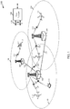
- the air-to-ground wireless communication system 100 includes a number of ground stations (or cells) 105, ATs 115, and a core network 130.
- the ground stations 105 may communicate with the ATs 115 under the control of a ground station controller (not shown), which may be part of the core network 130 or the ground stations 105 in various embodiments.
- Ground stations 105 may communicate control information and/or user data with the core network 130 through backhaul links 120.
- the ground stations 105 may communicate, either directly or indirectly, with each other over backhaul links 135, which may be wired or wireless communication links.
- the air-to-ground wireless communication system 100 may support operation on multiple carriers (waveform signals of different frequencies).
- Multi-carrier transmitters can transmit modulated signals simultaneously on the multiple carriers.
- each communication link 125 may be a multi-carrier signal modulated according to various radio technologies.
- Each modulated signal may be sent on a different carrier and may carry control information (e.g., reference signals, control channels, etc.), overhead information, data, etc.
- the ground stations 105 may wirelessly communicate with an AT 115 via one or more ground station antennas. Each of the ground station 105 sites may provide communication coverage for a respective geographic coverage area 110.
- the geographic coverage area 110 may be large compared to the cell size of a ground-to-ground wireless system. In some cases the geographic area may have a radius of hundreds of kilometers. Due to the large geographic coverage area, the distance between an AT and a serving ground station may be larger than 100 kilometers. The distance may be larger than the distance between a traditional mobile device and base station. In some cases a subset of ground station antenna elements including one or more widely spaced elements may be configured to achieve wide coverage and antenna diversity.
- a ground station 105 may be referred to as a base station, a base transceiver station, a radio ground station, an access point, a radio transceiver, a basic service set (BSS), an extended service set (ESS), a NodeB, eNodeB (eNB), or some other suitable terminology.
- the geographic coverage area 110 for a ground station 105 may be divided into sectors making up only a portion of the coverage area (not shown). There may be overlapping coverage areas for different technologies.
- the core network 130 may communicate with the ground stations 105 via a backhaul links 120 (e.g., S1, etc.).
- the ground stations 105 may also communicate with one another, e.g., directly or indirectly via backhaul links 135 (e.g., X2, etc.) and/or via backhaul links 120 (e.g., through core network 130).
- the air-to-ground wireless communication system 100 may support synchronous or asynchronous operation. For synchronous operation, the ground stations 105 may have similar frame timing, and transmissions from different ground stations 105 may be approximately aligned in time. For asynchronous operation, the ground stations 105 may have different frame timing, and transmissions from different ground stations 105 may not be aligned in time.
- the techniques described herein may be used for either synchronous or asynchronous operations.
- the ATs 115 are dispersed throughout the air-to-ground wireless communication system 100.
- An AT may be located on an airborne vehicle such as an airplane, helicopter, or balloon. In some cases the AT 115 may also be located on the ground.
- An AT 115 may also be referred to as a mobile device, a user equipment, a mobile station, a subscriber station, a mobile unit, a subscriber unit, a wireless unit, a remote unit, a mobile device, a wireless device, a wireless communications device, a remote device, a mobile subscriber station, an access terminal, a mobile terminal, a wireless terminal, a remote terminal, a user agent, a mobile client, a client, or some other suitable terminology.
- An AT 115 may be a two-way radio, a radio cellular phone, a wireless modem, a wireless communication device, a handheld device, a wireless local loop (WLL) station, or the like.
- WLL wireless local loop
- the communication links 125 shown in the air-to-ground wireless communication system 100 may include uplink (UL) transmissions from an AT 115 to a ground station 105, and/or downlink (DL) transmissions, from a ground station 105 to an AT 115.
- the downlink transmissions may also be called forward link transmissions, while the uplink transmissions may also be called reverse link transmissions.
- the communication links 125 may involve a significant propagation delay.
- a ground station 105 or AT 115 may utilize beamforming techniques to improve the signal-to-noise ratio for a communication link 125.
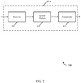
- a block diagram 200 illustrates an exemplary AT 115-a for establishing a wireless communications link with a ground station 105 in accordance with various embodiments.
- the AT 115-a may be an example of one or more aspects of an AT 115 described with reference to FIG. 1 .
- the AT 115-a may include a receiver 205, an access module 210, and/or a transmitter 215.
- the AT 115-a may also include a processor (not shown). Each of these components may be in communication with each other.
- These components of the AT 115-a may, individually or collectively, be implemented with one or more application-specific integrated circuits (ASICs) adapted to perform some or all of the applicable functions in hardware.
- ASICs application-specific integrated circuits
- the functions may be performed by one or more other processing units (or cores), on one or more integrated circuits.
- other types of integrated circuits may be used (e.g ., Structured/Platform ASICs, Field Programmable Gate Arrays (FPGAs), and other Semi-Custom ICs), which may be programmed in any manner known in the art.
- the functions of each unit may also be implemented, in whole or in part, with instructions embodied in a memory, formatted to be executed by one or more general or application-specific processors.
- Each of the noted modules may be a means for performing one or more functions related to operation of the AT 115-a.
- the receiver 205 may receive information such as packets, user data, and/or control information including synchronization signals and access messages.
- the received information may be demodulated, descrambled, de-interleaved, and decoded.
- the information may be passed on to the access module 210, and to other components of the AT 115-a.
- the receiver 205 may include a single antenna, or it may include a plurality of antennas.
- the access module 210 may perform steps to establish a communication link 125 with a ground station 105 including determining a timing offset. This timing offset may enable the ground station 105 to receive access messages within a time period allotted to receiving such messages. Information and instructions may be passed to a processor (not shown), the receiver 205, the transmitter 215, or other components of the AT 115-a.
- the transmitter 215 may transmit the one or more signals received from the access module 210 or other components of the AT 115-a. For example, the transmitter 215 may transmit an initial access message to a ground station 105 based at least in part on the determined timing offset. In some embodiments, the transmitter 215 may be collocated with the receiver 205 in a transceiver module (not shown). The transmitter 215 may include a single antenna, or it may include a plurality of antennas.
- a block diagram 300 illustrates an exemplary AT 115-b for establishing a wireless communications link with a ground station 105 in accordance with various embodiments.
- the AT 115-b may be an example of one or more aspects of an AT 115 described with reference to FIGs. 1 and/or 2.
- the AT 115-b may include a receiver 205, an access module 210-a, and/or a transmitter 215.
- the access module 210-a may be an example of the access module 210 described with reference to FIG. 2 .
- the access module 210-a may include an access message module 305, a timing module 310, and a location module 315.
- These components of the AT 115-b may, individually or collectively, be implemented with one or more application-specific integrated circuits (ASICs) adapted to perform some or all of the applicable functions in hardware.
- ASICs application-specific integrated circuits
- the functions may be performed by one or more other processing units (or cores), on one or more integrated circuits.
- other types of integrated circuits may be used (e.g ., Structured/Platform ASICs, Field Programmable Gate Arrays (FPGAs), and other Semi-Custom ICs), which may be programmed in any manner known in the art.
- the functions of each unit may also be implemented, in whole or in part, with instructions embodied in a memory, formatted to be executed by one or more general or application-specific processors.
- Each of the noted modules may be a means for performing one or more functions related to operation of the AT 115-b.
- the receiver 205 may perform the functions described above. In particular, it may receive an access response message from a ground station, which may include a timing alignment value. It may also receive a contention resolution message. In some cases, the receiver 205 may also receive data on a downlink from the ground station, the data being transmitted on the downlink via a beamforming configuration at the ground station.
- the transmitter 215 may perform the functions described above. Additionally, the transmitter 215 may transmit a connection message that includes location information. In particular, the transmitter 215 may transmit a Radio Resource Control (RRC) connection request message to the ground station 105, the RRC connection request message comprising location information of the AT. The transmitting of the connection message may be based at least in part on an adjusted timing offset. In some cases, the transmitter 215 may transmit an initial access message to be received at the ground station by a subset of ground station antenna elements comprising one or more widely spaced elements configured to achieve wide coverage and antenna diversity. In one embodiment, the transmitter 215 may transmit data on an uplink to the ground station 105, the data being received on the uplink via a beamforming configuration at the ground station 105.
- RRC Radio Resource Control
- the initial access message module 305 may send and receive messages relating to an access procedure in order to establish a communication link 125 with a ground station 105. These messages include, but are not limited to an initial access message, an access response message, a connection message, and a contention resolution message.
- the initial access message and the connection message may be sent with the transmitter 215.
- the access response message and the contention resolution message may be received in coordination with the receiver 205.
- the timing module 310 may determine a timing offset based at least in part on a round trip propagation delay between the AT 115 and a ground station 105. Since the propagation delay may depend in part on the location of the AT, the timing module 310 may determine the timing offset in coordination with the location module 315.
- the location module may identify the AT location and compare the AT location to a ground station location.
- a block diagram 400 illustrates an exemplary access module 210-b for establishing a wireless communications link with a ground station 105 in accordance with various embodiments.
- the access module 210-b may be an example of one or more aspects of an access module 210 described with reference to FIGs. 2 and/or 3.
- the access module 210-b may include an access message module 305-a, a timing module 310-a, and a location module 315-a, which may perform the functions described above with reference to FIG. 3 .
- the access message module 305-a may include an initial access message module 405, a response message module 410, a connection message module 415, and a contention resolution module 420.
- the timing module 310-a may include an offset module 425 and an offset adjustment module 430.
- the location module 315-a may include an AT location module 435 and a ground station (GS) location module 440.
- GS ground station
- These components of the access module 210-b may, individually or collectively, be implemented with one or more application-specific integrated circuits (ASICs) adapted to perform some or all of the applicable functions in hardware.
- ASICs application-specific integrated circuits
- the functions may be performed by one or more other processing units (or cores), on one or more integrated circuits.
- other types of integrated circuits may be used (e.g ., Structured/Platform ASICs, Field Programmable Gate Arrays (FPGAs), and other Semi-Custom ICs), which may be programmed in any manner known in the art.
- the functions of each unit may also be implemented, in whole or in part, with instructions embodied in a memory, formatted to be executed by one or more general or application-specific processors.
- Each of the noted modules may be a means for performing one or more functions related to operation of the access module 210-b.
- the initial access message module 405 may, in coordination with the transmitter 215, transmit an initial access message to the ground station 105 based at least in part on a determined timing offset in coordination with the offset module 425.
- the initial access message transmission may convey a Random Access Radio Network Temporary Identifier (RA-RNTI).
- RA-RNTI Random Access Radio Network Temporary Identifier
- the RA-RNTI may be determined by the PRACH transmission time and frequency, and in some cases does not depend on the initial access message.
- the initial access message may comprise 6 bits of information.
- the initial access module may select at random one of 64 available Random Access Channel (RACH) preambles. There is a chance that this selection may result in the selection of a RACH preamble that is the same as the preamble selected by another AT during the same period, resulting in colliding requests.
- RACH Random Access Channel
- the response message module 410 may, in coordination with the receiver 205, receive an access response message from the ground station which may include a timing alignment value.
- the response message module 410 may pass this timing alignment value on to the offset adjustment module 430.
- the access response message may comprise at least a radio network temporary identifier (RNTI) and an uplink grant resource, wherein the uplink grant resource should reserve resources sufficient for an uplink transmission of a connection message with AT location information described below; and the RNTI may be, for example, a cell-RNTI (C-RNTI) or a temporary cell RNTI (TEMP-CRNTI).
- the response message module 410 may process this information to coordinate future communications with the ground station 105 over a communication link 125. In some cases this includes determining which uplink shared channel (UL-SCH) resources the AT 115 may use.
- UL-SCH uplink shared channel
- the connection message module 415 may, in coordination with the transmitter 215, transmit a connection message to a ground station 105.
- the connection message may be transmitted based at least in part on an adjusted timing offset in coordination with the offset adjustment module 430.
- the connection message may include location information from the AT location module 435.
- the connection message may be an RRC connection request message, and may include one or more of an RRC connection request, an RRC re-establishment request, a random value, a Temporary Mobile Subscriber Identity (TMSI), or a connection establishment cause.
- TMSI Temporary Mobile Subscriber Identity
- the connection message may be based at least in part on whether the AT is establishing a new communication link 125 with a ground station 105, or re-establishing a previously existing connection.
- the contention resolution module 420 may, in coordination with the receiver 205, receive a contention resolution message.
- a contention resolution message may be addressed to an AT 115 with a specific TMSI or random number. It may include a C-RNTI to be used for further communications.
- a contention resolution message may be addressed to an AT 115 with a specific TMSI or random number. It may include a C-RNTI to be used for further communications.
- one or more ATs 115 may not receive a contention resolution message.
- an AT 115 that did not receive a contention resolution message may send another initial access message.
- the offset module 425 may determine a timing offset which may be based at least in part on a propagation delay between the AT 115 and the ground station 105.
- the propagation delay may be based on the distance between the AT and the ground station. In one example, the distance may be larger than 100 kilometers. Due to the large distance, the propagation delay may be sufficiently long that without an offset the initial access message may be received at the ground station 105 outside a detection window for initial access messages.
- the timing offset may be determined prior to receiving any messages from the ground station.
- the timing offset may be determined in coordination with the AT location module 435 and the GS location module 440. Transmitting according to the timing offset may result in the initial access message being received within the detection window, but it may not be synchronized at the beginning of the detection window.
- An initial access message may include a cyclic prefix and/or a guard time so that the message may be correctly received in cases when the transmission is not synchronized with the detection window.
- the offset adjustment module 430 may adjust the timing offset based at least in part on a timing alignment value received as part of an access response message from a ground station 105.
- the adjusted timing offset may result in communications that are synchronized or approximately synchronized between an AT 115 and a ground station 105.
- the timing offset may need to be adjusted one or more times based on changes in the location of the AT 115. These adjustments may be made based on one or more timing alignment messages received from a ground station 105. In some embodiments, adjustments may be made independent of timing alignment messages.
- the AT location module 435 may identify an AT location.
- the AT location may be identified from a Global Positioning System (GPS) device.
- GPS Global Positioning System
- the AT location may also be determined in coordination with other aircraft navigation equipment.
- the AT location module 435 may contain components that may determine the location of the AT 115 independent of information received from other aircraft navigation units, including aircraft GPs devices.
- the AT location information may comprise one or more or as latitude, longitude, altitude, heading velocity or a time stamp. It may be configured to facilitate beamforming between an AT 115 and a ground station 105 on the uplink or downlink.
- the AT location may coordinate with the GS location module 440 and pass information to the offset module 425.
- the GS location module 440 may identify a ground station location.
- the location module 315-a may compare the AT location to the ground station location and pass information to the offset module 425.
- the ground station module may be determined prior to receiving any communication from the ground station, or it may be received from the ground station 105. In the case that the ground station location is determined prior to receiving location information from the ground station 105, the GS location module 440 may access the ground station location from a stored set of ground station locations.
- a stored set of ground station locations may be stored in a memory located on the AT 115.
- a ground station location may also be entered by an AT operator. The ground station location may be selected based on information about the coverage area 110 of a ground station 105, in comparison to an AT location received from the AT location module 435.
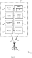
- a block diagram 500 illustrates an exemplary AT 115-c in communication with a ground station 105.
- the AT 115-c and its components may be an example of one or more aspects of a AT 115 described with reference to FIGs. 1 , 2 , and/or 3.
- the components of AT 115-c may also have similar functionality to the components of discussed above.
- the access module 210 may be an example of the access module 210 with reference to FIGs. 2 , 3 , and/or 4.
- the receiver 205 and the transmitter 215 may perform the functions previously described with reference to FIG. 2-3 .
- the AT 115-c may also include a processor module 505, a memory 510, software 515, a modem 520, a network interface module 525, and a GPS interface module 530, which each may be in communication, directly or indirectly, with each other ( e.g., over one or more buses).
- the receiver 205 and transmitter 215 may be configured to communicate bidirectionally with a core network 130 through one or more ground stations 105.
- the AT 115-c may also include a non-transitory computer-readable medium storing instructions executable by a processor that may be included in the processor module 505.
- the memory 510 in particular may also be in electronic communication with the processor module 505.
- the memory 510 may include random access memory (RAM) and read-only memory (ROM).
- the memory 510 may also store computer-readable, computer-executable software code 515 containing instructions that are configured to, when executed, cause the processor module 505 to perform various functions described herein (e.g ., call processing, database management, message routing, etc.).
- the software code 515 may not be directly executable by the processor module 505 but may be configured to cause the computer, e . g ., when compiled and executed, to perform functions described herein.
- the processor module 505 may include an intelligent hardware device, e.g ., a central processing unit (CPU), a microcontroller, an application-specific integrated circuit (ASIC), etc.
- the AT 115-c may communicate with the ground station 105 using the modem 520 according to an interface managed by the network interface module 525.
- the modem in coordination with receiver 205 may demodulate, descramble, de-interleave, and/or decode information received from the ground station 105.
- the modem may also encode, interleave, scramble and modulate data to be transmitted in coordination with the network interface module 525 and transmitter 215.
- the modulation/demodulation scheme may be determined based on the technology of the air-to-ground wireless communication system 100, and it may also be based on the quality of the communication link 125.
- the GPS interface module 530 may receive location information from an aircraft GPS unit. It may also coordinate with other aircraft navigation units and send location information to the AT location module 435. The GPS interface module 530 may coordinate with the AT location module 435 to determine the reliability of location information. A reliability determination may depend on the availability of information from different AT navigation units.
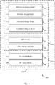
- a diagram 600 illustrates an access procedure that may be used to establish a communication link 125 with a ground station 105.
- the ground station 105, geographic coverage area 110, AT 115, and communication link 125 may be examples of the components of the air-to-ground wireless communication system 100 with reference to FIGs. 1 , 2 , 3 , 4 , and/or 5.
- the procedure may be initiated when the AT 115 enters the geographic coverage area 110 of the ground station 105.
- the initial access message 605 may be generated by the initial access module 405 and transmitted by transmitter 215 to a ground station 105. It may comprise a random number selected by the AT 115 to distinguish it from other ATs 115 that may be attempting to initiate communications with the ground station 105. In some cases, the initial access may be the first indication that a ground station 105 receives indicating that an AT 115 is about to request a communication link 125. In other cases, the ground station 105 may have received an indication from the core network 130 that the AT 115 is entering its coverage area 110. The initial access message may be transmitted according to a timing offset determined by offset module 425.
- the access response message 610 may be transmitted by a ground station 105 and received by AT 115 through the coordination of a receiver 205 and a response message module 410.
- the access response message 610 may be sent by the ground station 105 after receiving an initial access message 605.
- the access response message 610 may include a timing alignment value.
- connection message 615 may be generated by the connection message module 415 and transmitted by transmitter 215 to a ground station 105. It may include a request to establish an RRC interface with the ground station 105. The connection message 615 may be transmitted according to an adjusted timing offset based on the timing alignment value received in the access response message 610.
- the contention resolution message 620 may be transmitted by a ground station 105 and received by AT 115 through the coordination of a receiver 205 and a contention resolution module 420. It may be used to resolve collisions caused by selection of a non-unique initial access message 605. In some cases, reception of a contention resolution message 620 addressed to an AT 115 may be an indication to proceed with communications over link 125.
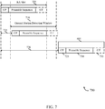
- a diagram 700 illustrates the relation between a received initial access message and a ground station detection window 710.
- a transmission from an AT 115 such as the initial access message 605 with reference to FIG. 6 , may be associated with a random access (RA) transmission slot 705. Due to propagation delay between an AT 115 and a ground station 105, the ground station detection window 710 for the initial access message may begin after a delay.
- RA random access
- the initial access message 605 may comprise a cyclic prefix (CP) 725, a preamble sequence 730, and a guard time (GT) 735.
- CP cyclic prefix
- GT guard time
- the geographic coverage area of a cell may be small enough so that any mobile device within the coverage area will transmit with a short propagation delay 715 so that the preamble sequence 730 falls within the detection window 710.
- An initial access message 605 transmitted with a timing offset may approximate a transmission with a short propagation delay 715, so that the preamble sequence 730 falls within the ground station detection window 710 regardless of the location of the AT 115.
- An adjusted timing offset may be even more precise than the initial timing offset, and may result in even more reliable reception of transmissions.
- the ground station 105 may be able to successfully receive an initial access message if the CP 725 or the GT 735 fall outside of the detection window.
- the offset module 425 may determine a timing offset.
- the timing offset may be based at least in part on a propagation delay between an AT 115 and a ground station 105.
- the offset module 425 may be means for determining a timing offset based at least in part on a propagation delay between the AT 115 and a ground station 105.
- the initial access module 405, in coordination with the transmitter 215, may transmit an initial access message based at least in part on a determined timing offset in coordination with the offset module 425.
- the initial access message transmission may convey an RA-RNTI.
- the initial access module 405 may be means for transmitting an initial access message to the ground station 105 based at least in part on the determined timing offset.
- the transmitter 215 may also be means for transmitting the initial access message to be received at the ground station by a subset of ground station antenna elements comprising one or more widely-spaced elements configured to achieve wide coverage and antenna diversity.
- the response message module 410 may, in coordination with the receiver 205, receive an access response message that includes a timing alignment value.
- the response message module 410 may pass this timing alignment value on to the offset adjustment module 430.
- the access response message may comprise at least a RNTI (e.g., either a cell-RNTI or a temporary cell-RNTI) and an uplink grant resource.
- the response message module 410 may be the means for receiving an access response message from the ground station that includes a timing alignment value.
- the offset adjustment module 430 may adjust the timing offset based at least in part on the timing advance value. This may be done in coordination with the offset module 425. Thus, the offset adjustment module 430 may be means for adjusting the timing offset based at least in part on the timing alignment value.
- the offset module 425 may determine a timing offset.
- the offset module 425 may determine the timing offset based on location information from the location module 315.
- the AT location module 435 may be the means for identifying an AT location, and in one embodiment, means for identifying the AT location from a GPS device.
- the GS location module may be means for accessing the ground station location from a stored set of ground station locations.
- the location module 315 may be means for comparing the AT location to a ground station location.
- the initial access module 405 may, in coordination with the transmitter 215, transmit an initial access message based at least in part on the determined timing offset in coordination with the offset module 425.
- the response message module 410 may, in coordination with the receiver 205, receive an access response message that includes a timing alignment value.
- the response message module 410 may pass this timing alignment value on to the offset adjustment module 430.
- the access response message may comprise at least a RNTI (e.g., either a cell-RNTI or a temporary cell-RNTI) and an uplink grant resource.
- the response message module 410 may be the means for receiving an access response message from the ground station that includes a timing alignment value.
- the offset adjustment module 430 may adjust the timing offset based at least in part on the timing advance value. This may be done in coordination with the offset module 425. Thus, the offset adjustment module 430 may be means for adjusting the timing offset based at least in part on the timing alignment value.
- the connection message module 415 may, in coordination with the transmitter 215, transmit a connection message to a ground station 105 that includes AT location information.
- the connection message may be transmitted based at least in part on an adjusted timing offset in coordination with the offset adjustment module 430.
- the location information may be received from the AT location module 435.
- the connection message may be an RRC connection request message or an RRC re-establishment request message, and may include one or more of a random value, a TMSI, or a connection establishment cause.
- the connection message module 415 may be means for transmitting a connection message that includes AT location information.
- the contention resolution module 420 may, in coordination with the receiver 205, receive a contention resolution message.
- a contention resolution message may be addressed to an AT 115 with a specific TMSI or random number. It may include a C-RNTI to be used for further communications.
- the contention resolution module 420 may means for receiving a contention resolution message.
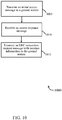
- FIG. 10 a flowchart shows a method 1000 for transmitting location information with an RRC connection request message.
- the method 1000 is described below with reference to one of the ATs 115 described with reference to FIGs. 1 , 2 , 3 , 4 , 5 , and/or 6.
- the initial access module 405 may, in coordination with the transmitter 215, transmit an initial access message to a ground station. In one embodiment, the transmission is based on a timing offset, but in another embodiment there is no initial timing offset. Thus, the initial access module 405 may be means for transmitting an initial access message to the ground station 105.
- the response message module 410 may, in coordination with the receiver 205, receive an access response message from the ground station 105.
- the connection message module 415 may, in coordination with the transmitter 215, transmit an RRC connection request message with AT location information to the ground station 105. The information location may be received from the AT location module 435.
- the connection message module 415 may be means for transmitting an RRC connection request message to the ground station, the RRC connection request message comprising location information of the AT.
- FIG. 11 a flowchart shows a method 1100 for establishing a wireless communications link at an AT.
- the method 1100 is described below with reference to one of the ATs 115 described with reference to FIGs. 1 , 2 , 3 , 4 , 5 , and/or 6.
- the initial access module 405 may, in coordination with the transmitter 215, transmit an initial access message to a ground station.
- the response message module 410 may, in coordination with the receiver 205, receive an access response message from the ground station 105.
- the connection message module 415 may, in coordination with the transmitter 215, transmit an RRC connection request message with location information to the ground station 105.
- the receiver 205 may receive data on a downlink from the ground station 105.
- the data may be received in coordination with the modem 520 and the network interface module 525.
- the receiver 205 may be means for receiving data on a downlink from the ground station 105, the data being transmitted on the downlink via a beamforming configuration at the ground station 105.
- the transmitter 215 may transmit data on an uplink to the ground station 105.
- the data may be transmitted in coordination with the modem 520 and the network interface module 525.
- the transmitter 215 may be means for transmitting data on an uplink to the ground station 105, the data being received on the uplink via a beamforming configuration at the ground station 105.
- a CDMA system may implement a radio technology such as CDMA2000, Universal Terrestrial Radio Access (UTRA), etc.
- CDMA2000 covers IS-2000, IS-95, and IS-856 standards.
- IS-2000 Releases 0 and A are commonly referred to as CDMA2000 IX, IX, etc.
- IS-856 (TIA-856) is commonly referred to as CDMA2000 1xEV-DO, High Rate Packet Data (HRPD), etc.
- UTRA includes Wideband CDMA (WCDMA) and other variants of CDMA.
- a TDMA system may implement a radio technology such as Global System for Mobile Communications (GSM).
- GSM Global System for Mobile Communications
- An OFDMA system may implement a radio technology such as Ultra Mobile Broadband (UMB), Evolved UTRA (E-UTRA), IEEE 802.11 (Wi-Fi), IEEE 802.16 (WiMAX), IEEE 802.20, Flash-OFDM, etc.
- UMB Ultra Mobile Broadband
- E-UTRA Evolved UTRA
- Wi-Fi Wi-Fi
- WiMAX IEEE 802.16
- IEEE 802.20 Flash-OFDM
- UTRA and E-UTRA are part of Universal Mobile Telecommunication System (UMTS).
- 3GPP Long Term Evolution (LTE) and LTE-Advanced (LTE-A) are new releases of UMTS that use E-UTRA.
- UTRA, E-UTRA, UMTS, LTE, LTE-A, and GSM are described in documents from an organization named "3rd Generation Partnership Project" (3GPP).
- CDMA2000 and UMB are described in documents from an organization named "3rd Generation Partnership Project 2" (3GPP2).
- 3GPP2 3rd Generation Partnership Project 2
- the techniques described herein may be used for the systems and radio technologies mentioned above as well as other systems and radio technologies.
- the description above describes an LTE system for purposes of example, and LTE terminology is used in much of the description above, although the techniques are applicable beyond LTE applications.
- Information and signals may be represented using any of a variety of different technologies and techniques.
- data, instructions, commands, information, signals, bits, symbols, and chips that may be referenced throughout the above description may be represented by voltages, currents, electromagnetic waves, magnetic fields or particles, optical fields or particles, or any combination thereof.
- DSP digital signal processor
- ASIC application specific integrated circuit
- FPGA field programmable gate array
- a general-purpose processor may be a microprocessor, but in the alternative, the processor may be any conventional processor, controller, microcontroller, or state machine.
- a processor may also be implemented as a combination of computing devices, e.g., a combination of a DSP and a microprocessor, multiple microprocessors, one or more microprocessors in conjunction with a DSP core, or any other such configuration.
- the functions described herein may be implemented in hardware, software executed by a processor, firmware, or any combination thereof. If implemented in software executed by a processor, the functions may be stored on or transmitted over as one or more instructions or code on a computer-readable medium. Other examples and implementations are within the scope of the appended claims. For example, due to the nature of software, functions described above can be implemented using software executed by a processor, hardware, firmware, hardwiring, or combinations of any of these. Features implementing functions may also be physically located at various positions, including being distributed such that portions of functions are implemented at different physical locations.
- Computer-readable media includes both computer storage media and communication media including any medium that facilitates transfer of a computer program from one place to another.
- a storage medium may be any available medium that can be accessed by a general purpose or special purpose computer.
- computer-readable media can comprise RAM, ROM, EEPROM, CD-ROM or other optical disk storage, magnetic disk storage or other magnetic storage devices, or any other medium that can be used to carry or store desired program code means in the form of instructions or data structures and that can be accessed by a general-purpose or special-purpose computer, or a general-purpose or special-purpose processor.
- any connection is properly termed a computer-readable medium.
- Disk and disc include compact disc (CD), laser disc, optical disc, digital versatile disc (DVD), floppy disk and blu-ray disc where disks usually reproduce data magnetically, while discs reproduce data optically with lasers. Combinations of the above are also included within the scope of computer-readable media.
Landscapes
- Engineering & Computer Science (AREA)
- Computer Networks & Wireless Communication (AREA)
- Signal Processing (AREA)
- Physics & Mathematics (AREA)
- Astronomy & Astrophysics (AREA)
- General Physics & Mathematics (AREA)
- Aviation & Aerospace Engineering (AREA)
- Mobile Radio Communication Systems (AREA)
- Synchronisation In Digital Transmission Systems (AREA)
- Radio Transmission System (AREA)
Applications Claiming Priority (3)
| Application Number | Priority Date | Filing Date | Title |
|---|---|---|---|
| US201361918437P | 2013-12-19 | 2013-12-19 | |
| US14/265,123 US9615344B2 (en) | 2013-12-19 | 2014-04-29 | Enhanced random access procedure for air-to-ground communications |
| PCT/US2014/069326 WO2015094815A1 (en) | 2013-12-19 | 2014-12-09 | Enhanced random access procedure for air-to-ground communications |
Publications (2)
| Publication Number | Publication Date |
|---|---|
| EP3085187A1 EP3085187A1 (en) | 2016-10-26 |
| EP3085187B1 true EP3085187B1 (en) | 2020-04-01 |
Family
ID=53401657
Family Applications (1)
| Application Number | Title | Priority Date | Filing Date |
|---|---|---|---|
| EP14816548.3A Active EP3085187B1 (en) | 2013-12-19 | 2014-12-09 | Enhanced random access procedure for air-to-ground communications |
Country Status (6)
Families Citing this family (26)
| Publication number | Priority date | Publication date | Assignee | Title |
|---|---|---|---|---|
| US9929794B2 (en) | 2015-10-15 | 2018-03-27 | Honeywell International Inc. | Long term evolution (LTE) air to ground communication enhancements associated with uplink synchronization |
| US11140715B2 (en) * | 2016-10-26 | 2021-10-05 | Qualcomm Incorporated | Waveform-dependent random access channel procedure |
| KR102317192B1 (ko) * | 2016-11-04 | 2021-10-26 | 한국전자통신연구원 | 열차 통신 네트워크의 상향링크 신호 수신 방법 및 장치 |
| CN107425892B (zh) * | 2017-06-22 | 2019-02-26 | 清华大学 | 基于多波束组播的空地协同通信方法和装置 |
| WO2019019164A1 (zh) * | 2017-07-28 | 2019-01-31 | 北京小米移动软件有限公司 | 无人机管理方法及装置、通信连接建立方法及装置 |
| US11514801B2 (en) * | 2017-08-28 | 2022-11-29 | Beijing Xiaomi Mobile Software Co., Ltd. | Flight control method, device and system |
| WO2019041125A1 (zh) * | 2017-08-29 | 2019-03-07 | 北京小米移动软件有限公司 | 执行接入控制的方法、装置和系统 |
| CN107749883B (zh) * | 2017-10-20 | 2020-10-23 | 广州海格通信集团股份有限公司 | 基于窄带波束定向天线的飞行器地空宽带通信链路方法 |
| US11553527B2 (en) | 2018-06-01 | 2023-01-10 | Samsung Electronics Co., Ltd. | Method and system for handling random access procedure in non-terrestrial communication system |
| US11963237B2 (en) | 2018-10-30 | 2024-04-16 | Interdigital Patent Holdings, Inc. | Methods, apparatus, systems and procedures for distance dependent random access channel (RACH) preamble selection in non-terrestrial networks (NTNS) |
| WO2020146506A2 (en) * | 2019-01-08 | 2020-07-16 | Apple Inc. | Random access procedure for nr based satellite communication |
| US11553542B2 (en) * | 2019-01-11 | 2023-01-10 | Qualcomm Incorporated | Device-to-device signaling |
| GB2582136B (en) | 2019-03-11 | 2022-08-03 | Airspan Ip Holdco Llc | Timing adjustment within a wireless communication system for a moving vehicle |
| US11653350B2 (en) | 2019-05-03 | 2023-05-16 | Qualcomm Incorporated | Variable uplink response and/or scheduling delays for non-terrestrial networks |
| JP7554187B2 (ja) * | 2019-05-13 | 2024-09-19 | パナソニック インテレクチュアル プロパティ コーポレーション オブ アメリカ | 送信装置、受信装置、送信方法及び受信方法 |
| US11540324B2 (en) | 2019-06-18 | 2022-12-27 | Qualcomm Incorporated | Variable random access channel contention resolution window in a non-terrestrial network |
| CN118612889A (zh) * | 2019-09-30 | 2024-09-06 | 中兴通讯股份有限公司 | 在无线通信网络中配置传输资源并执行rach的系统和方法 |
| CN112751603B (zh) * | 2019-10-29 | 2022-09-16 | 华为技术有限公司 | 用于卫星通信的方法和装置 |
| CN110996329A (zh) * | 2019-11-26 | 2020-04-10 | 北京长焜科技有限公司 | 在地空覆盖中增强lte fdd系统接入距离的方法 |
| US12335892B2 (en) | 2020-04-01 | 2025-06-17 | Qualcomm Incorporated | Data channel timelines in wireless communications systems |
| US11937193B2 (en) * | 2020-04-01 | 2024-03-19 | Qualcomm Incorporated | Timing improvements for wireless communications systems |
| US11659599B2 (en) * | 2020-04-28 | 2023-05-23 | Qualcomm Incorporated | Random access preamble transmission timing offset |
| KR102781524B1 (ko) * | 2020-06-01 | 2025-03-17 | 엘지전자 주식회사 | 패스트 빔 스티어링 시스템 기반 주파수 그래디언트 메타서페이스 장치 및 이에 대한 방법 |
| US12034582B2 (en) | 2021-03-05 | 2024-07-09 | Peraton Labs Inc. | Adaptive radio frequency communication |
| US11658755B2 (en) | 2021-03-05 | 2023-05-23 | Perspecta Labs Inc. | Interference mitigation in multi-antenna system |
| US20240048227A1 (en) * | 2022-08-05 | 2024-02-08 | Samsung Electronics Co., Ltd. | Triggering timing synchronization in non-terrestrial networks |
Family Cites Families (29)
| Publication number | Priority date | Publication date | Assignee | Title |
|---|---|---|---|---|
| JP2000022618A (ja) * | 1998-07-03 | 2000-01-21 | Hitachi Ltd | 基地局およびアンテナビームの制御方法 |
| AR052957A1 (es) | 2005-03-29 | 2007-04-11 | Qualcomm Inc | Tecnicas para facilitar la transferencia de comunicacion |
| US8036205B2 (en) | 2005-06-13 | 2011-10-11 | Qualcomm Incorporated | Methods and apparatus for supporting uplinks with remote base stations |
| CN101268631A (zh) * | 2005-07-20 | 2008-09-17 | 高通股份有限公司 | 用于提供基站位置信息和利用位置信息来支持时基和/或频率校正的方法和装置 |
| US7991362B2 (en) * | 2005-07-20 | 2011-08-02 | Qualcomm Incorporated | Methods and apparatus for supporting timing and/or frequency corrections in a wireless communications system |
| US8798638B2 (en) * | 2005-07-20 | 2014-08-05 | Qualcomm Incorporated | Methods and apparatus for providing base station position information and using position information to support timing and/or frequency corrections |
| US7912471B2 (en) * | 2006-01-04 | 2011-03-22 | Wireless Technology Solutions Llc | Initial connection establishment in a wireless communication system |
| US20070161347A1 (en) * | 2006-01-10 | 2007-07-12 | Lucent Technologies, Inc. | Enabling a digital wireless service for a mobile station across two different wireless communications environments |
| US8682357B2 (en) * | 2006-05-02 | 2014-03-25 | Intellectual Ventures Holding 81 Llc | Paging in a wireless network |
| US8295243B2 (en) * | 2006-08-21 | 2012-10-23 | Qualcomm Incorporated | Method and apparatus for random access in an orthogonal multiple-access communication system |
| WO2008104098A1 (en) | 2007-02-28 | 2008-09-04 | Huawei Technologies Co., Ltd. | System and method for determining a transmit timing for sommunication in a radio communication system |
| WO2009022881A2 (en) * | 2007-08-15 | 2009-02-19 | Lg Electronics Inc. | Dedicated signature allocation and choice |
| KR101447750B1 (ko) | 2008-01-04 | 2014-10-06 | 엘지전자 주식회사 | 랜덤 액세스 과정을 수행하는 방법 |
| WO2010047545A2 (ko) | 2008-10-22 | 2010-04-29 | 엘지전자 주식회사 | 광대역 지원을 위한 다중 캐리어 결합 상황에서 효과적인 초기 접속 방식 |
| EP2400674A4 (en) | 2009-02-18 | 2017-03-22 | LG Electronics Inc. | Signal transmitting/receiving method for a relay node, and relay node using the method |
| US8634313B2 (en) * | 2009-06-19 | 2014-01-21 | Qualcomm Incorporated | Method and apparatus that facilitates a timing alignment in a multicarrier system |
| WO2011043711A1 (en) | 2009-10-09 | 2011-04-14 | Telefonaktiebolaget L M Ericsson (Publ) | Extended cell range |
| US8442518B2 (en) * | 2010-02-01 | 2013-05-14 | ADS-B Technologies, LLC | ADS-B link augmentation system (ALAS) |
| US8917593B2 (en) * | 2010-03-18 | 2014-12-23 | Qualcomm Incorporated | Random access design in a multiple component carrier communication network |
| EP2427018B1 (en) * | 2010-09-07 | 2016-02-17 | Alcatel Lucent | Access to a wireless communications network by a transceiver equipment selecting a non-zero timing advance value used for sending a Random Access Channel preamble to a LTE base station |
| JP2012065198A (ja) * | 2010-09-16 | 2012-03-29 | Toshiba Corp | 移動通信システム、無線基地局、無線端末および通信制御方法 |
| US8819264B2 (en) | 2011-07-18 | 2014-08-26 | Verizon Patent And Licensing Inc. | Systems and methods for dynamically switching between unicast and multicast delivery of media content in a wireless network |
| US8824408B2 (en) * | 2011-08-11 | 2014-09-02 | Industrial Technology Research Institute | Method of handling random access procedure associated to cell deactivation |
| CN102938931B (zh) * | 2011-08-15 | 2016-05-18 | 重庆航讯时代科技有限责任公司 | 大范围非同步上行接入方法及装置 |
| CN102938670B (zh) * | 2011-08-15 | 2015-02-11 | 航通互联网信息服务有限责任公司 | 用于飞机的地空宽带无线通信系统及方法 |
| US9301323B2 (en) * | 2011-09-16 | 2016-03-29 | Telefonaktiebolaget Lm Ericsson (Publ) | Contention-free random access procedure in wireless networks |
| WO2013063789A1 (en) | 2011-11-04 | 2013-05-10 | Beijing Weibang Yuanhang Wireless Technology Co., Ltd | Data communication methods and apparatus |
| US20130201910A1 (en) | 2012-02-08 | 2013-08-08 | Telefonaktiebolaget Lm Ericsson (Publ) | Uplink Timing Alignment |
| US8971280B2 (en) * | 2012-04-20 | 2015-03-03 | Ofinno Technologies, Llc | Uplink transmissions in a wireless device |
-
2014
- 2014-04-29 US US14/265,123 patent/US9615344B2/en active Active
- 2014-12-09 JP JP2016541381A patent/JP2017502590A/ja not_active Withdrawn
- 2014-12-09 CN CN201480068718.2A patent/CN105830519B/zh not_active Expired - Fee Related
- 2014-12-09 WO PCT/US2014/069326 patent/WO2015094815A1/en active Application Filing
- 2014-12-09 KR KR1020167018905A patent/KR101821318B1/ko not_active Expired - Fee Related
- 2014-12-09 EP EP14816548.3A patent/EP3085187B1/en active Active
-
2018
- 2018-11-28 JP JP2018222242A patent/JP6585270B2/ja not_active Expired - Fee Related
Non-Patent Citations (1)
| Title |
|---|
| None * |
Also Published As
| Publication number | Publication date |
|---|---|
| US20150181544A1 (en) | 2015-06-25 |
| KR101821318B1 (ko) | 2018-01-23 |
| JP6585270B2 (ja) | 2019-10-02 |
| CN105830519B (zh) | 2019-10-01 |
| JP2019071616A (ja) | 2019-05-09 |
| CN105830519A (zh) | 2016-08-03 |
| KR20160101033A (ko) | 2016-08-24 |
| US9615344B2 (en) | 2017-04-04 |
| WO2015094815A1 (en) | 2015-06-25 |
| JP2017502590A (ja) | 2017-01-19 |
| EP3085187A1 (en) | 2016-10-26 |
Similar Documents
| Publication | Publication Date | Title |
|---|---|---|
| EP3085187B1 (en) | Enhanced random access procedure for air-to-ground communications | |
| US11596001B2 (en) | Method and apparatus for performing multiple RACH procedures | |
| US9572121B2 (en) | Methods and apparatus for timing synchronization during a wireless uplink random access procedure | |
| EP3053366B1 (en) | Sequence generation for shared spectrum | |
| US8681701B2 (en) | Mobile communications devices and transmission methods for transmitting machine type communication data thereof | |
| KR20200052885A (ko) | 동기화 신호 블록 및 제어 리소스 세트 멀티플렉싱 | |
| KR102744380B1 (ko) | 디바이스-투-디바이스 통신들에서 스케줄링 할당 송신들 | |
| US12395861B2 (en) | Methods and apparatus for reducing overhead in a random access procedure | |
| US20220132586A1 (en) | Method and apparatus for performing enhanced random access procedure | |
| EP4316155A1 (en) | Random access channel preamble transmission parameters based on coverage enhancement level | |
| US11523438B2 (en) | Determining device locations based on random access channel signaling | |
| US20120122466A1 (en) | Method and Arrangement in a Communications Network | |
| CN117083975A (zh) | 基于覆盖增强等级的随机接入信道前导码的跳频模式 | |
| KR20130125075A (ko) | 반 이중 단말 및 반 이중 단말의 랜덤 억세스 방법 | |
| EP4568414A2 (en) | Sidelink positioning resource conflict management | |
| US20220330328A1 (en) | Random access method, device, and medium | |
| WO2024019813A1 (en) | Sidelink positioning resource selection and reselection based on sidelink discontinuous reception (sl-drx) configuration |
Legal Events
| Date | Code | Title | Description |
|---|---|---|---|
| PUAI | Public reference made under article 153(3) epc to a published international application that has entered the european phase |
Free format text: ORIGINAL CODE: 0009012 |
|
| 17P | Request for examination filed |
Effective date: 20160512 |
|
| AK | Designated contracting states |
Kind code of ref document: A1 Designated state(s): AL AT BE BG CH CY CZ DE DK EE ES FI FR GB GR HR HU IE IS IT LI LT LU LV MC MK MT NL NO PL PT RO RS SE SI SK SM TR |
|
| AX | Request for extension of the european patent |
Extension state: BA ME |
|
| DAX | Request for extension of the european patent (deleted) | ||
| RIC1 | Information provided on ipc code assigned before grant |
Ipc: H04W 56/00 20090101ALI20190613BHEP Ipc: H04W 74/00 20090101AFI20190613BHEP Ipc: H04B 7/185 20060101ALI20190613BHEP Ipc: H04W 74/08 20090101ALI20190613BHEP |
|
| GRAP | Despatch of communication of intention to grant a patent |
Free format text: ORIGINAL CODE: EPIDOSNIGR1 |
|
| STAA | Information on the status of an ep patent application or granted ep patent |
Free format text: STATUS: GRANT OF PATENT IS INTENDED |
|
| INTG | Intention to grant announced |
Effective date: 20190828 |
|
| GRAS | Grant fee paid |
Free format text: ORIGINAL CODE: EPIDOSNIGR3 |
|
| GRAJ | Information related to disapproval of communication of intention to grant by the applicant or resumption of examination proceedings by the epo deleted |
Free format text: ORIGINAL CODE: EPIDOSDIGR1 |
|
| GRAL | Information related to payment of fee for publishing/printing deleted |
Free format text: ORIGINAL CODE: EPIDOSDIGR3 |
|
| STAA | Information on the status of an ep patent application or granted ep patent |
Free format text: STATUS: REQUEST FOR EXAMINATION WAS MADE |
|
| INTC | Intention to grant announced (deleted) | ||
| GRAR | Information related to intention to grant a patent recorded |
Free format text: ORIGINAL CODE: EPIDOSNIGR71 |
|
| STAA | Information on the status of an ep patent application or granted ep patent |
Free format text: STATUS: GRANT OF PATENT IS INTENDED |
|
| GRAA | (expected) grant |
Free format text: ORIGINAL CODE: 0009210 |
|
| STAA | Information on the status of an ep patent application or granted ep patent |
Free format text: STATUS: THE PATENT HAS BEEN GRANTED |
|
| INTG | Intention to grant announced |
Effective date: 20200219 |
|
| AK | Designated contracting states |
Kind code of ref document: B1 Designated state(s): AL AT BE BG CH CY CZ DE DK EE ES FI FR GB GR HR HU IE IS IT LI LT LU LV MC MK MT NL NO PL PT RO RS SE SI SK SM TR |
|
| REG | Reference to a national code |
Ref country code: GB Ref legal event code: FG4D |
|
| REG | Reference to a national code |
Ref country code: AT Ref legal event code: REF Ref document number: 1253038 Country of ref document: AT Kind code of ref document: T Effective date: 20200415 Ref country code: CH Ref legal event code: EP |
|
| REG | Reference to a national code |
Ref country code: DE Ref legal event code: R096 Ref document number: 602014063249 Country of ref document: DE |
|
| REG | Reference to a national code |
Ref country code: IE Ref legal event code: FG4D |
|
| PG25 | Lapsed in a contracting state [announced via postgrant information from national office to epo] |
Ref country code: BG Free format text: LAPSE BECAUSE OF FAILURE TO SUBMIT A TRANSLATION OF THE DESCRIPTION OR TO PAY THE FEE WITHIN THE PRESCRIBED TIME-LIMIT Effective date: 20200701 |
|
| REG | Reference to a national code |
Ref country code: NL Ref legal event code: MP Effective date: 20200401 |
|
| REG | Reference to a national code |
Ref country code: LT Ref legal event code: MG4D |
|
| PG25 | Lapsed in a contracting state [announced via postgrant information from national office to epo] |
Ref country code: NL Free format text: LAPSE BECAUSE OF FAILURE TO SUBMIT A TRANSLATION OF THE DESCRIPTION OR TO PAY THE FEE WITHIN THE PRESCRIBED TIME-LIMIT Effective date: 20200401 Ref country code: CZ Free format text: LAPSE BECAUSE OF FAILURE TO SUBMIT A TRANSLATION OF THE DESCRIPTION OR TO PAY THE FEE WITHIN THE PRESCRIBED TIME-LIMIT Effective date: 20200401 Ref country code: LT Free format text: LAPSE BECAUSE OF FAILURE TO SUBMIT A TRANSLATION OF THE DESCRIPTION OR TO PAY THE FEE WITHIN THE PRESCRIBED TIME-LIMIT Effective date: 20200401 Ref country code: PT Free format text: LAPSE BECAUSE OF FAILURE TO SUBMIT A TRANSLATION OF THE DESCRIPTION OR TO PAY THE FEE WITHIN THE PRESCRIBED TIME-LIMIT Effective date: 20200817 Ref country code: FI Free format text: LAPSE BECAUSE OF FAILURE TO SUBMIT A TRANSLATION OF THE DESCRIPTION OR TO PAY THE FEE WITHIN THE PRESCRIBED TIME-LIMIT Effective date: 20200401 Ref country code: GR Free format text: LAPSE BECAUSE OF FAILURE TO SUBMIT A TRANSLATION OF THE DESCRIPTION OR TO PAY THE FEE WITHIN THE PRESCRIBED TIME-LIMIT Effective date: 20200702 Ref country code: IS Free format text: LAPSE BECAUSE OF FAILURE TO SUBMIT A TRANSLATION OF THE DESCRIPTION OR TO PAY THE FEE WITHIN THE PRESCRIBED TIME-LIMIT Effective date: 20200801 Ref country code: NO Free format text: LAPSE BECAUSE OF FAILURE TO SUBMIT A TRANSLATION OF THE DESCRIPTION OR TO PAY THE FEE WITHIN THE PRESCRIBED TIME-LIMIT Effective date: 20200701 Ref country code: SE Free format text: LAPSE BECAUSE OF FAILURE TO SUBMIT A TRANSLATION OF THE DESCRIPTION OR TO PAY THE FEE WITHIN THE PRESCRIBED TIME-LIMIT Effective date: 20200401 |
|
| REG | Reference to a national code |
Ref country code: AT Ref legal event code: MK05 Ref document number: 1253038 Country of ref document: AT Kind code of ref document: T Effective date: 20200401 |
|
| PG25 | Lapsed in a contracting state [announced via postgrant information from national office to epo] |
Ref country code: RS Free format text: LAPSE BECAUSE OF FAILURE TO SUBMIT A TRANSLATION OF THE DESCRIPTION OR TO PAY THE FEE WITHIN THE PRESCRIBED TIME-LIMIT Effective date: 20200401 Ref country code: HR Free format text: LAPSE BECAUSE OF FAILURE TO SUBMIT A TRANSLATION OF THE DESCRIPTION OR TO PAY THE FEE WITHIN THE PRESCRIBED TIME-LIMIT Effective date: 20200401 Ref country code: LV Free format text: LAPSE BECAUSE OF FAILURE TO SUBMIT A TRANSLATION OF THE DESCRIPTION OR TO PAY THE FEE WITHIN THE PRESCRIBED TIME-LIMIT Effective date: 20200401 |
|
| PG25 | Lapsed in a contracting state [announced via postgrant information from national office to epo] |
Ref country code: AL Free format text: LAPSE BECAUSE OF FAILURE TO SUBMIT A TRANSLATION OF THE DESCRIPTION OR TO PAY THE FEE WITHIN THE PRESCRIBED TIME-LIMIT Effective date: 20200401 |
|
| REG | Reference to a national code |
Ref country code: DE Ref legal event code: R097 Ref document number: 602014063249 Country of ref document: DE |
|
| PG25 | Lapsed in a contracting state [announced via postgrant information from national office to epo] |
Ref country code: RO Free format text: LAPSE BECAUSE OF FAILURE TO SUBMIT A TRANSLATION OF THE DESCRIPTION OR TO PAY THE FEE WITHIN THE PRESCRIBED TIME-LIMIT Effective date: 20200401 Ref country code: AT Free format text: LAPSE BECAUSE OF FAILURE TO SUBMIT A TRANSLATION OF THE DESCRIPTION OR TO PAY THE FEE WITHIN THE PRESCRIBED TIME-LIMIT Effective date: 20200401 Ref country code: ES Free format text: LAPSE BECAUSE OF FAILURE TO SUBMIT A TRANSLATION OF THE DESCRIPTION OR TO PAY THE FEE WITHIN THE PRESCRIBED TIME-LIMIT Effective date: 20200401 Ref country code: DK Free format text: LAPSE BECAUSE OF FAILURE TO SUBMIT A TRANSLATION OF THE DESCRIPTION OR TO PAY THE FEE WITHIN THE PRESCRIBED TIME-LIMIT Effective date: 20200401 Ref country code: IT Free format text: LAPSE BECAUSE OF FAILURE TO SUBMIT A TRANSLATION OF THE DESCRIPTION OR TO PAY THE FEE WITHIN THE PRESCRIBED TIME-LIMIT Effective date: 20200401 Ref country code: SM Free format text: LAPSE BECAUSE OF FAILURE TO SUBMIT A TRANSLATION OF THE DESCRIPTION OR TO PAY THE FEE WITHIN THE PRESCRIBED TIME-LIMIT Effective date: 20200401 Ref country code: EE Free format text: LAPSE BECAUSE OF FAILURE TO SUBMIT A TRANSLATION OF THE DESCRIPTION OR TO PAY THE FEE WITHIN THE PRESCRIBED TIME-LIMIT Effective date: 20200401 |
|
| PLBE | No opposition filed within time limit |
Free format text: ORIGINAL CODE: 0009261 |
|
| STAA | Information on the status of an ep patent application or granted ep patent |
Free format text: STATUS: NO OPPOSITION FILED WITHIN TIME LIMIT |
|
| PG25 | Lapsed in a contracting state [announced via postgrant information from national office to epo] |
Ref country code: SK Free format text: LAPSE BECAUSE OF FAILURE TO SUBMIT A TRANSLATION OF THE DESCRIPTION OR TO PAY THE FEE WITHIN THE PRESCRIBED TIME-LIMIT Effective date: 20200401 Ref country code: PL Free format text: LAPSE BECAUSE OF FAILURE TO SUBMIT A TRANSLATION OF THE DESCRIPTION OR TO PAY THE FEE WITHIN THE PRESCRIBED TIME-LIMIT Effective date: 20200401 |
|
| 26N | No opposition filed |
Effective date: 20210112 |
|
| PG25 | Lapsed in a contracting state [announced via postgrant information from national office to epo] |
Ref country code: SI Free format text: LAPSE BECAUSE OF FAILURE TO SUBMIT A TRANSLATION OF THE DESCRIPTION OR TO PAY THE FEE WITHIN THE PRESCRIBED TIME-LIMIT Effective date: 20200401 |
|
| REG | Reference to a national code |
Ref country code: CH Ref legal event code: PL |
|
| PG25 | Lapsed in a contracting state [announced via postgrant information from national office to epo] |
Ref country code: MC Free format text: LAPSE BECAUSE OF FAILURE TO SUBMIT A TRANSLATION OF THE DESCRIPTION OR TO PAY THE FEE WITHIN THE PRESCRIBED TIME-LIMIT Effective date: 20200401 |
|
| REG | Reference to a national code |
Ref country code: BE Ref legal event code: MM Effective date: 20201231 |
|
| PG25 | Lapsed in a contracting state [announced via postgrant information from national office to epo] |
Ref country code: LU Free format text: LAPSE BECAUSE OF NON-PAYMENT OF DUE FEES Effective date: 20201209 Ref country code: IE Free format text: LAPSE BECAUSE OF NON-PAYMENT OF DUE FEES Effective date: 20201209 |
|
| PG25 | Lapsed in a contracting state [announced via postgrant information from national office to epo] |
Ref country code: CH Free format text: LAPSE BECAUSE OF NON-PAYMENT OF DUE FEES Effective date: 20201231 Ref country code: LI Free format text: LAPSE BECAUSE OF NON-PAYMENT OF DUE FEES Effective date: 20201231 |
|
| PG25 | Lapsed in a contracting state [announced via postgrant information from national office to epo] |
Ref country code: TR Free format text: LAPSE BECAUSE OF FAILURE TO SUBMIT A TRANSLATION OF THE DESCRIPTION OR TO PAY THE FEE WITHIN THE PRESCRIBED TIME-LIMIT Effective date: 20200401 Ref country code: MT Free format text: LAPSE BECAUSE OF FAILURE TO SUBMIT A TRANSLATION OF THE DESCRIPTION OR TO PAY THE FEE WITHIN THE PRESCRIBED TIME-LIMIT Effective date: 20200401 Ref country code: CY Free format text: LAPSE BECAUSE OF FAILURE TO SUBMIT A TRANSLATION OF THE DESCRIPTION OR TO PAY THE FEE WITHIN THE PRESCRIBED TIME-LIMIT Effective date: 20200401 |
|
| PG25 | Lapsed in a contracting state [announced via postgrant information from national office to epo] |
Ref country code: MK Free format text: LAPSE BECAUSE OF FAILURE TO SUBMIT A TRANSLATION OF THE DESCRIPTION OR TO PAY THE FEE WITHIN THE PRESCRIBED TIME-LIMIT Effective date: 20200401 |
|
| PG25 | Lapsed in a contracting state [announced via postgrant information from national office to epo] |
Ref country code: BE Free format text: LAPSE BECAUSE OF NON-PAYMENT OF DUE FEES Effective date: 20201231 |
|
| PGFP | Annual fee paid to national office [announced via postgrant information from national office to epo] |
Ref country code: GB Payment date: 20221109 Year of fee payment: 9 Ref country code: FR Payment date: 20221110 Year of fee payment: 9 Ref country code: DE Payment date: 20221109 Year of fee payment: 9 |
|
| REG | Reference to a national code |
Ref country code: DE Ref legal event code: R119 Ref document number: 602014063249 Country of ref document: DE |
|
| GBPC | Gb: european patent ceased through non-payment of renewal fee |
Effective date: 20231209 |
|
| PG25 | Lapsed in a contracting state [announced via postgrant information from national office to epo] |
Ref country code: DE Free format text: LAPSE BECAUSE OF NON-PAYMENT OF DUE FEES Effective date: 20240702 |
|
| PG25 | Lapsed in a contracting state [announced via postgrant information from national office to epo] |
Ref country code: GB Free format text: LAPSE BECAUSE OF NON-PAYMENT OF DUE FEES Effective date: 20231209 |
|
| PG25 | Lapsed in a contracting state [announced via postgrant information from national office to epo] |
Ref country code: FR Free format text: LAPSE BECAUSE OF NON-PAYMENT OF DUE FEES Effective date: 20231231 |
|
| PG25 | Lapsed in a contracting state [announced via postgrant information from national office to epo] |
Ref country code: GB Free format text: LAPSE BECAUSE OF NON-PAYMENT OF DUE FEES Effective date: 20231209 Ref country code: FR Free format text: LAPSE BECAUSE OF NON-PAYMENT OF DUE FEES Effective date: 20231231 Ref country code: DE Free format text: LAPSE BECAUSE OF NON-PAYMENT OF DUE FEES Effective date: 20240702 |