EP3084935B1 - Verfahren zum herstellen einer elektrisch leitfähigen und mechanisch festen verbindung zwischen leitern einer rotorwicklung und einer lamelle eines kommutators - Google Patents
Verfahren zum herstellen einer elektrisch leitfähigen und mechanisch festen verbindung zwischen leitern einer rotorwicklung und einer lamelle eines kommutators Download PDFInfo
- Publication number
- EP3084935B1 EP3084935B1 EP14805588.2A EP14805588A EP3084935B1 EP 3084935 B1 EP3084935 B1 EP 3084935B1 EP 14805588 A EP14805588 A EP 14805588A EP 3084935 B1 EP3084935 B1 EP 3084935B1
- Authority
- EP
- European Patent Office
- Prior art keywords
- conductor
- commutator
- conductors
- embossing
- core
- Prior art date
- Legal status (The legal status is an assumption and is not a legal conclusion. Google has not performed a legal analysis and makes no representation as to the accuracy of the status listed.)
- Not-in-force
Links
- 239000004020 conductor Substances 0.000 title claims description 178
- 238000004804 winding Methods 0.000 title claims description 16
- 238000000034 method Methods 0.000 title claims description 13
- 238000004519 manufacturing process Methods 0.000 title claims description 7
- 238000004049 embossing Methods 0.000 claims description 92
- 241000446313 Lamella Species 0.000 claims description 26
- 238000003825 pressing Methods 0.000 claims description 8
- 230000005540 biological transmission Effects 0.000 claims 1
- 239000007858 starting material Substances 0.000 description 11
- 238000003466 welding Methods 0.000 description 10
- 238000002485 combustion reaction Methods 0.000 description 4
- 238000006073 displacement reaction Methods 0.000 description 4
- XEEYBQQBJWHFJM-UHFFFAOYSA-N Iron Chemical group [Fe] XEEYBQQBJWHFJM-UHFFFAOYSA-N 0.000 description 3
- 230000006978 adaptation Effects 0.000 description 3
- 239000000463 material Substances 0.000 description 2
- 230000007704 transition Effects 0.000 description 2
- 150000001875 compounds Chemical class 0.000 description 1
- 230000001419 dependent effect Effects 0.000 description 1
- 230000000994 depressogenic effect Effects 0.000 description 1
- 238000000605 extraction Methods 0.000 description 1
- 238000003780 insertion Methods 0.000 description 1
- 230000037431 insertion Effects 0.000 description 1
- 229910052742 iron Inorganic materials 0.000 description 1
- 238000003475 lamination Methods 0.000 description 1
- 230000004048 modification Effects 0.000 description 1
- 238000012986 modification Methods 0.000 description 1
- 230000006641 stabilisation Effects 0.000 description 1
- 238000011105 stabilization Methods 0.000 description 1
Images



Classifications
-
- H—ELECTRICITY
- H01—ELECTRIC ELEMENTS
- H01R—ELECTRICALLY-CONDUCTIVE CONNECTIONS; STRUCTURAL ASSOCIATIONS OF A PLURALITY OF MUTUALLY-INSULATED ELECTRICAL CONNECTING ELEMENTS; COUPLING DEVICES; CURRENT COLLECTORS
- H01R39/00—Rotary current collectors, distributors or interrupters
- H01R39/02—Details for dynamo electric machines
- H01R39/32—Connections of conductor to commutator segment
-
- H—ELECTRICITY
- H01—ELECTRIC ELEMENTS
- H01R—ELECTRICALLY-CONDUCTIVE CONNECTIONS; STRUCTURAL ASSOCIATIONS OF A PLURALITY OF MUTUALLY-INSULATED ELECTRICAL CONNECTING ELEMENTS; COUPLING DEVICES; CURRENT COLLECTORS
- H01R43/00—Apparatus or processes specially adapted for manufacturing, assembling, maintaining, or repairing of line connectors or current collectors or for joining electric conductors
-
- H—ELECTRICITY
- H01—ELECTRIC ELEMENTS
- H01R—ELECTRICALLY-CONDUCTIVE CONNECTIONS; STRUCTURAL ASSOCIATIONS OF A PLURALITY OF MUTUALLY-INSULATED ELECTRICAL CONNECTING ELEMENTS; COUPLING DEVICES; CURRENT COLLECTORS
- H01R43/00—Apparatus or processes specially adapted for manufacturing, assembling, maintaining, or repairing of line connectors or current collectors or for joining electric conductors
- H01R43/28—Apparatus or processes specially adapted for manufacturing, assembling, maintaining, or repairing of line connectors or current collectors or for joining electric conductors for wire processing before connecting to contact members, not provided for in groups H01R43/02 - H01R43/26
-
- H—ELECTRICITY
- H01—ELECTRIC ELEMENTS
- H01R—ELECTRICALLY-CONDUCTIVE CONNECTIONS; STRUCTURAL ASSOCIATIONS OF A PLURALITY OF MUTUALLY-INSULATED ELECTRICAL CONNECTING ELEMENTS; COUPLING DEVICES; CURRENT COLLECTORS
- H01R2201/00—Connectors or connections adapted for particular applications
- H01R2201/10—Connectors or connections adapted for particular applications for dynamoelectric machines
Definitions
- a method for producing an electrically conductive and mechanically fixed connection between conductors of a rotor winding and a lamination of a commutator is known.
- displacements may occur on a commutator blade in connection with making the cohesive connection of the two conductors.
- a displacement of the wire forming the base against the commutator occur.
- the same thing can happen with respect to the top layer - the wire lying on the base - with respect to the base.
- a method for cohesive connection between a commutator and conductors by means of embossing tools are eg in the publications EP0632934 and DE4002106 described.
- the measures proposed here aim to avoid such changes in the manufacturing process.
- the conductor which is to be materially connected to the lamella, ie the base is first pressed against an embossing core, wherein the conductor is thereby deformed.
- an area of the surface is adapted at least to a portion of a contour of the embossing core.
- the embossing core is then removed and replaced by the commutator.
- the conductor with the adapted surface is placed on a lamella and connected or firmly bonded with it.
- This has the advantage that thereby the surface of the conductor, here the pad, the surface of the commutator can be adjusted. Functionally, this means that a kind of positive engagement between the pad and the commutator can be made possible.
- the commutator likewise has a cylindrical surface or if each individual lamella has a section-wise cylindrical surface at the intended place for the integral connection, the corresponding pairing on the lamella of the commutator results in a certain degree of correspondence.
- lateral forces in the circumferential direction
- the fact that the base is displaced relative to the lamella corresponds to the contour of the embossing core of the contour of the commutator, which corresponds to the contour of the pad, which faces the blade, the contour of the blade and thus the commutator after adjusting.
- the pressing takes place at the embossing core by means of a stamping die.
- the die presses the other conductor, ie the top layer, on the conductor, which represents the base, whereby the conductor or the base is adapted to the contour of the embossing core.
- a further contour is impressed in the conductor pressed against the embossing core, which is positioned on the side facing away from the lamella. This has the advantage that thereby adaptation to the pad facing side of the top layer is possible.
- an intermediate embossing core is used, which consists of a harder material than the ladder, so that the intermediate embossing core, the further contour in the head, ie the pad, presses. It is provided here that the intermediate embossing core on the side facing the blade or the embossing core convex and concave on the side facing away from the lamella or the embossing core.
- the conductors are arranged one above the other and are guided in a guide device in the direction of the embossing core.
- the superposed conductors are arranged in a starting position at a position corresponding to a groove position of the rotor winding. Furthermore, it is provided that by pressing against the embossing core, an electrical contact resistance between the conductor on the lamella (base) and the lamella is increased.
- FIG. 1 shows a schematic longitudinal section through a starter, which is shown here as a specific embodiment of an electrical machine 1 according to the invention.
- electric machine 1 for an internal combustion engine has as a drive element by way of example a starter pinion 2, which is brought to start the internal combustion engine 4 in engagement with a ring gear 3 of the internal combustion engine.
- the starter pinion is mounted on a drive shaft 5, as indicated by the double arrow, axially displaceable.
- the starter pinion 2 is rotatably coupled to the drive shaft 5.
- the starter pinion 2 is between a retracted out-of-position position and an advanced engagement position with the ring gear third of the internal combustion engine 4 adjusted via an engagement relay 6.
- the engagement relay 6 is an electromagnetic drive and comprises at least one energizable relay winding 7 and a lifting armature 8, which is pulled axially in energizing the relay winding 7 in this.
- the lifting armature 8 is kinematically coupled to the starter pinion 2 via an engaging lever 9, so that the axial adjusting movement of the lifting armature 8 between a rest position and an adjustment or working position in a corresponding axial adjusting movement of the starter pinion 2 between the non-functional position and the engaged position is used.
- a control unit controls the relay winding 7.
- the rotating drive movement to the drive shaft 5 and the starter pinion 2 is generated by means of an electric motor 11, which is coupled via a gear, which is designed as a planetary gear 12, with the shaft 5.
- a gear which is designed as a planetary gear 12
- the drive shaft 5 and thus also the starter pinion 2 is rotated.
- the electric motor 11 is energized by means of a commutator 13 and brushes 14 and 15 sliding thereon.
- a rotor winding 63 of the rotor 60 is traversed by the electric current via the commutator 13.
- FIG. 2 shows in a sectional side view of the commutator 13 with a commutator 20.
- This commutator is on its outer circumference substantially cylindrical.
- At one axial end in the FIG. 2 on the left is shown how two conductors 23 and 26 are positioned.
- On the Kommutatorlamelle 20 is initially the end of the conductor 23.
- On this end of the conductor 23, the end of the conductor 26 is located.
- the conductor 23 is connected via a cohesive connection 28 with the commutator blade 20 and the conductor 26 via a cohesive connection 29 with the conductor 23.
- FIG. 3a a first step is shown.
- the embossing core 32 here has a cylindrical outer contour which, for example, corresponds to the outer diameter of the outer diameter of the commutator 13, on which this conductor 23 is to be positioned later.
- Above the conductor 23 is indicated in a dashed line representation that the conductor 23 emerges from a different radius position than shown by the solid line from a groove of an anchor.
- FIG. 3b is shown as an embossing stamp is brought to the conductor 23 (arrow).
- the conductor 23 is guided or held in place by a guide device 38, and here in the example by the two guide jaws 40 and 41, which are arranged in the circumferential direction on both sides of the conductor 23.
- the punch 35 is fed to the conductor 23 at a certain speed v to the conductor 23 in the radial direction, which is represented by a dotted line.
- the radial direction corresponds to a radial of the circular outer contour of the embossing core 32.
- 3a to 3c is not shown that all documents and all upper layers or all conductors 23 and all conductors 26 are arranged around the embossing core 32.
- a rotor as shown here has twenty-one fins, and accordingly, twenty-one conductors 23 and twenty-one conductors 26 are disposed on the outer circumference.
- the embossing of the conductor 23, as for example in FIGS. 3b and 3c is provided, for example, according to a conventional and known to those skilled lateral against each other moving the top layer and the conductor 26 instead.
- each conductor element which is known to have approximately U-shaped configuration and at one end is designed as a base and at the other end as a top layer, separately for themselves, as in FIGS.
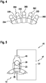
- FIG. 4 shows an end view of the commutator 13 and arranged on the individual Kommutatorlamellen 20 ends of the conductors 23 and 26, that of the pad and top layer.
- Such conductors 23 and 26 are usually bent in such machines (starter) in an approximately U-shaped (coil elements) and bent the electromagnetic properties or requirements.
- starter in an approximately U-shaped (coil elements)
- coil elements are arranged on the outer circumference of the commutator 13.
- These coil elements integrally comprise two coil sides, which are each arranged in a different groove of the iron core of the rotor.
- each two coil sides are at one end, ie at the end of the rotor iron, which faces away from the commutator 13, usually integrally connected to each other (winding head).
- the two coil sides occur in the form of confined elements and finally axially aligned ends, which in here FIG. 4 are shown out.
- each two ends of a one-piece conductor element recognizable.
- the conductors 23A and 26A are a one-piece conductor which is arranged with the corresponding ends as a base and top layer on the commutator or commutator bars 20. So after the ends of the conductors 23 and 26 as in FIG.
- the commutator blade 20 is connected to a welding power source 47.
- a top layer ie here a conductor 26, contacted by a welding electrode 49.
- the welding process initiated by switching on the welding power source 47 and ultimately by the welding current in the Transition area between the conductor 26 and the conductor 23 and in the transition area between the conductor 23 and the commutator 20 so welded together, as in FIG. 2 is indicated by the cohesive compounds 28 and 29.
- the welding device 45 is removed and the rotor can be further processed in a further step.
- FIGS. 1 to 5 a method for producing an electrically conductive and mechanically fixed connection 28 and 29 between conductors 23 and 26 of a rotor winding and a commutator 20 of a commutator 13 is shown.
- the conductors 23 and 26 are arranged such that one of the conductors 23 is arranged between the other conductor 26 and the commutator lamella 20. Thereafter, the one conductor 23 with a portion of its surface with the commutator 20 is firmly bonded.
- the conductor 23 is thereby formed and thereby adapted the mentioned area of the surface at least to a portion of an outer contour 43 of the embossing core 32. Thereafter, the embossing core 32 is removed and replaced by the commutator 13. The conductor 23 with the adapted surface is placed on a Kommutatorlamelle 20 and fastened cohesively with her. The pressing of the embossing core 32 by means of an embossing punch 35, wherein the stamper 35 presses the conductor 23 on the side facing away from the embossing core 32 side and impresses there a contour.
- the conductor 26 is inserted into the embossed contour on the side facing away from the commutator 20 of the conductor 23 and then the conductor 26 to the conductor 23 and the conductor 23 to the commutator 20 is firmly bonded.
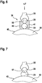
- FIG. 6 an alternative embodiment is shown.
- a conductor 23 is positioned directly on the outer circumference, ie the outer contour 43 of the embossing core 32.
- the conductor 26 In the radial direction (see. FIG. 3b ) is positioned on the conductor 23, the conductor 26 so that in a radial line between the conductor 26 and the embossing core 32 of the conductor 23rd is arranged.
- the embossing punch 35 is moved toward the conductor 26 (v, F). This stamp 35 engages the conductor 26 with a concavity and pushes it onto the conductor 23, FIG.
- the two conductors 23 and 26 may also be analogous to the above-mentioned embodiment by a guide device 38 so that the introduction of the concavity 57 and the adjustment of the conductor 23 to the outer contour 43 of the die 32 passes as unhindered.
- the embossing core 32 from the totality of all conductors 23 and 26, which are arranged, for example, annularly around the embossing core 32, pulled out and the commutator 13 is inserted.
- FIG. 4 It then results in an arrangement as they are already in FIG. 4 is shown.
- the connections are the same as already for FIG. 4 described.
- the conductor 26 is connected to the conductor 23 by cohesive connection 29 with this and the conductor 23 is connected by cohesive connection 28 with a commutator 20.
- the process of connecting is as already for FIG. 5 described.
- a method for producing an electrically conductive and mechanically fixed connection 28, 29 between conductors 23, 26, a rotor winding and a commutator blade 20 of a commutator 13 is also provided here.
- the conductors 23 and 26 are arranged in such a way that one of the conductors 23 is arranged between the other conductor 26 and the lamella 20.
- the conductor 23 is materially connected to a portion of its surface with the blade 20.
- the conductor 23, which is to be materially bonded to the lamella 20, is first pressed against an embossing core 32, wherein the conductor 32 is thereby deformed such that thereby the area of the surface is adapted at least to a portion of an outer contour 43 of the embossing core 32.
- the embossing core 32 is removed and replaced by the commutator 13.
- the conductor 23 is placed with the adapted surface on a blade 20 and fastened with it cohesively.
- the pressing takes place on the embossing core 32 by means of an embossing punch 35, wherein the embossing punch 35 presses the conductor 26 on the conductor 23, which is adapted to the contour of the embossing core 32.
- conductor 23 is a further contour 55 impressed, which is positioned on the side facing away from the blade 20.
- FIG. 8 a first step of a third embodiment is shown.
- the conductor 23 is positioned on the outer contour 43 of the embossing core 32.
- guide jaws 40, 41 of a guide device 38 may be arranged to prevent lateral deflection of the conductor 23.
- an intermediate embossing core 61 is positioned.
- the conductor 26 is set on the intermediate embossing core 61, which is gripped radially outwardly by an embossing punch 35.
- the conductor 23 is thus arranged between the embossing core 32 and the intermediate embossing core 61 and the conductor 26 between the intermediate embossing core 61 and the die 35.
- the intermediate embossing core preferably has a cylindrical contour 64 on its side facing the conductor 23. On the side of the intermediate embossing core 61, which faces away from the conductor 23, this also has a cylindrical contour 66. Both cylindrical contours 64 and 66 can have the same radius. the radius of the conductor 26 - if this is circular - corresponds.
- the conductor 23 is adapted to the embossing core 32 side facing the outer contour 43.
- a contour is impressed, which corresponds substantially to the cylindrical contour 64 of the intermediate embossing core 61.
- the conductor 26 is pressed into the cylindrical contour 66. Due to the preferred characteristics of the cylindrical contour 64 described above, the conductor 23 is impressed with a cylindrical contour that essentially corresponds to the radius of the conductor 26.
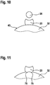
- FIG. 10 After pulling out the intermediate embossing core 61, FIG. 10 , And the removal of the stamping die 35 results in an arrangement as there is shown.
- FIG. 4 After the extraction of the embossing core 32 and the insertion of a commutator 13 results in a very similar representation as in FIG. 4 already shown. The difference is that there will be a slight gap between the conductors 23 and 26 since the intermediate embossing core 61 will cause a greater distance between both conductors.
- FIG. 10 in the situation, as they are very similar to analogously FIG. 4 arises, then, as already in FIG. 5 shown, the corresponding connection between the commutator bars and the conductor 23 and the conductor 23 and the conductor 26 are made.
- This embodiment also shows a method for producing an electrically conductive, mechanically fixed connection between conductors 23 and 26 of a rotor winding and a commutator blade 20 of a commutator 13.
- the conductors 23 and 26 are arranged such that one of the conductors 23 between the other conductor 26 and the lamella 20 is arranged. Thereafter, the one conductor 23 with a portion of its surface with the blade 20 is firmly bonded.
- the conductor 23, which is to be materially bonded to the lamella 20, is first pressed against an embossing core 32, wherein the conductor 23 is deformed and then the area of the surface is adapted at least to a portion of an outer contour 43 of the embossing core 32.
- the embossing core is removed and replaced by the commutator 13.
- the conductor 23 with the adapted surface is placed on a blade 20 and fastened with it cohesively.
- Pressing against the embossing core 32 is again effected by means of an embossing punch 35, wherein the embossing punch 35 presses the conductor 26 at least indirectly on the conductor 23, which is adapted to the contour of the embossing core 32.
- conductor 23 In the depressed to the embossing core 32 conductor 23 a further contour is impressed, which is positioned on the side facing away from the blade 20.
- an intermediate embossing core 61 is used, which consists of a harder material than the conductors 23 and 26, so that the intermediate embossing core 61 presses the further contour into the conductor 23.
- the intermediate embossing core 61 is convex on the side facing the lamella 20 and concave on the side facing away from the lamella 20.
- the conductors 23 and 26 are arranged one above the other and at least one of the two conductors - the conductor 23 and possibly both conductors - are guided in the direction of the embossing core 32 and commutator 13.
- the superimposed conductors are arranged in a starting position at a radial position corresponding to a slot position of the rotor winding.
- the superposed conductors 23 and 26 are arranged in a starting position at a position which corresponds between a slot position of the rotor winding and a position on the blade. Accordingly, in a modification of FIG. 3a the upper layer not the position immediately below the slot slot 70, but radially further inside, ie closer to the embossing core 32.
- the position of the conductor 23 would not be on the position that corresponds directly to the groove bottom of the groove shown there, but radially further inside so that the groove bottom in side view intersects the conductor cross-section. It is envisaged that by pressing against the embossing core, an electrical contact resistance between the conductor on the blade and the blade is increased.
- the adaptation of the conductor 23 to the contour of the embossing core 32 be designed so that not a cylindrical portion on the conductor 23 is formed, which corresponds to a cylindrical contour of the commutator 13, but it may for example also be provided that the contour of the conductor 23 has only a few points of contact with the commutator 20.
- the adaptation of the outer surface of the conductor 23 to the embossing core 32 can also lead, for example, to the fact that in the conductor 23 strips 75 arise, FIG. 11 .
- the conductor 23 on the commutator 13 and the Kommutatorlamelle 20 results in a significantly reduced Aufsitzquerrough leading to a higher electrical contact resistance between the conductor 23 on the blade 20 and the blade 20.
Landscapes
- Engineering & Computer Science (AREA)
- Manufacturing & Machinery (AREA)
- Manufacture Of Motors, Generators (AREA)
- Motor Or Generator Current Collectors (AREA)
Description
- Aus der
DE 4002106 ist ein Verfahren zum Herstellen einer elektrisch leitfähigen und mechanisch festen Verbindung zwischen Leitern einer Rotorwicklung und einer Lamelle eines Kommutators bekannt. Bei dem dort offenbarten Verfahren können im Zusammenhang mit dem Vornehmen der stoffschlüssigen Verbindung der beiden Leiter auf einer Kommutatorlamelle Verschiebungen eintreten. So kann beim Schweißen - d. h. beim Beaufschlagen mit radialen Schweißkräften auf den Kommutator und dessen Lamelle - und eventuellen in Umfangsrichtung wirkenden Kraftkomponenten eine Verschiebung des die Unterlage bildenden Drahtes gegenüber der Kommutatorlamelle eintreten. Gleiches kann bezüglich der Oberlage - dem auf der Unterlage liegenden Draht - in Bezug auf die Unterlage passieren. Verfahren zur stoffschlüssigen Verbindung zwischen einem Kommutator und Leitern mit Hilfe von Prägewerkzeugen werden z.B. in den DruckschriftenEP0632934 undDE4002106 beschrieben. - Mit den hier vorgeschlagenen Maßnahmen wird angestrebt, derartige Veränderungen beim Fertigungsprozess zu vermeiden.
- Gemäß den Merkmalen des unabhängigen Anspruchs 1 ist vorgesehen, dass der Leiter, der mit der Lamelle stoffschlüssig verbunden werden soll, also die Unterlage, zuerst an einen Prägekern gepresst wird, wobei der Leiter dabei umgeformt wird. Dabei wird ein Bereich der Oberfläche zumindest an einen Abschnitt einer Kontur des Prägekerns angepasst. Der Prägekern wird dann entfernt und durch den Kommutator ersetzt. Der Leiter mit der angepassten Oberfläche wird auf eine Lamelle aufgesetzt und mit ihr stoffschlüssig verbunden bzw. befestigt. Dies hat den Vorteil, dass dadurch die Oberfläche des Leiters, hier der Unterlage, der Oberfläche des Kommutators angepasst werden kann. Funktional bedeutet dies, dass dadurch eine Art Formschluss zwischen der Unterlage und dem Kommutator ermöglicht werden kann. So ist es möglich, die Kontur des Prägekerns zylindrisch auszuführen. Wenn der Kommutator ebenfalls eine zylindrische Oberfläche hat bzw. eine jede einzelne Lamelle an dem vorgesehenen Platz für die stoffschlüssige Verbindung eine abschnittweise zylindrische Oberfläche aufweist, ergibt sich durch die entsprechende Paarung auf der Lamelle des Kommutators eine gewissen Formentsprechung. Dies führt dazu, dass Querkräfte (in Umfangsrichtung) nicht oder nur deutlich vermindert dazu führen, dass die Unterlage gegenüber der Lamelle verschoben wird. Im einfachsten Fall entspricht somit die Kontur des Prägekerns der Kontur des Kommutators, wodurch nach dem Anpassen die Kontur der Unterlage, die der Lamelle zugewandt ist, der Kontur der Lamelle und damit dem Kommutator entspricht.
- Weitere Vorteile der Erfindung ergeben sich aus den Unteransprüchen. So ist beispielsweise vorgesehen, dass das Pressen an den Prägekern mittels eines Prägestempels erfolgt. Der Prägestempel drückt dabei den anderen Leiter, d. h. die Oberlage, auf den Leiter, der die Unterlage darstellt, wodurch der Leiter bzw. die Unterlage an die Kontur des Prägekerns angepasst wird. Gemäß einem weiteren Unteranspruch ist vorgesehen, dass in den an den Prägekern gedrückten Leiter eine weitere Kontur eingeprägt wird, die auf der Seite positioniert ist, die der Lamelle abgewandt ist. Dies hat den Vorteil, dass dadurch eine Anpassung an die der Unterlage zugewandte Seite der Oberlage möglich ist. Es wird dadurch erreicht, dass Umfangskräfte auf die Unterlage oder Oberlage nicht ohne Weiteres oder eine bestimmte Größe erreicht zu haben zu einem Verschieben der beiden Leiterenden auf der Lamelle führen. Gemäß einer weiteren Ausbildung der Erfindung ist vorgesehen, dass zum Prägen der weiteren Kontur ein Zwischenprägekern verwendet wird, der aus härterem Material als die Leiter besteht, sodass der Zwischenprägekern die weitere Kontur in den Leiter, d. h. die Unterlage, eindrückt. Es ist hierbei vorgesehen, dass der Zwischenprägekern auf der der Lamelle bzw. dem Prägekern zugewandten Seite konvex und auf der der Lamelle bzw. dem Prägekern abgewandten Seite konkav ausgebildet ist. Zum weiteren Stabilisieren beim Verfahren ist vorgesehen, dass die Leiter übereinander angeordnet sind und in einer Führungsvorrichtung in Richtung zum Prägekern geführt werden.
- Nach einer weiteren Ausgestaltung der Erfindung ist vorgesehen, dass die übereinander angeordneten Leiter in einer Ausgangsposition auf einer Position angeordnet sind, die einer Nutposition der Rotorwicklung entspricht. Desweiteren ist vorgesehen, dass durch das Pressen an den Prägekern ein elektrischer Übergangswiderstand zwischen dem Leiter auf der Lamelle (Unterlage) und der Lamelle erhöht wird.
- Die Erfindung ist in mehreren Figuren dargestellt. Es zeigen:
-
Figur 1 einen Längsschnitt durch eine elektrische Maschine mit einem Kommutator, -
Figur 3a bis 3c zeigt einen Verfahrensablauf zum Umformen eines Leiters, -
Figur 4 die Anordnung der Leiterelemente am Außenumfang eines Kommutators, -
Figur 6 eine erste Darstellung eines zweiten Ausführungsbeispiels des erfindungsgemäßen Verfahrens, -
Figur 7 einen zweiten Schritt des zweiten Ausführungsbeispiels, -
Figur 8 mit denFiguren 9 und10 ein drittes Ausführungsbeispiel. - Die
Figur 1 zeigt einen schematischen Längsschnitt durch einen Starter, der hier als spezielles Ausführungsbeispiel einer erfindungsgemäßen elektrischen Maschine 1 gezeigt ist. Die inFigur 1 dargestellte elektrische Maschine 1 (Starter) für eine Brennkraftmaschine weist als Antriebselement beispielhaft ein Starterritzel 2 auf, das zum Starten der Brennkraftmaschine 4 in Eingriff mit einem Zahnkranz 3 der Brennkraftmaschine gebracht wird. Das Starterritzel ist auf einer Antriebswelle 5, wie mit dem Doppelpfeil gekennzeichnet, axial verschieblich gelagert. Das Starterritzel 2 ist dabei drehfest mit der Antriebswelle 5 gekoppelt. Das Starterritzel 2 wird zwischen einer zurückgezogenen Außer-Funktions-Position und einer vorgerückten Eingriffsposition mit dem Zahnkranz 3 der Brennkraftmaschine 4 über ein Einrückrelais 6 verstellt. Das Einrückrelais 6 ist ein elektromagnetischer Antrieb und umfasst zumindest eine bestrombare Relaiswicklung 7 sowie einen Hubanker 8, der bei Bestromung der Relaiswicklung 7 in diese axial hineingezogen wird. Der Hubanker 8 ist über einen Einrückhebel 9 kinematisch mit dem Starterritzel 2 gekoppelt, sodass die axiale Verstellbewegung des Hubankers 8 zwischen einer Ruheposition und einer Verstell- bzw. Arbeitsposition in eine korrespondierende axiale Stellbewegung des Starterritzels 2 zwischen der Außer-Funktions-Position und der Eingriffsposition eingesetzt wird. Ein Steuergerät steuert die Relaiswicklung 7 an. - Die drehende Antriebsbewegung auf die Antriebswelle 5 bzw. das Starterritzel 2 wird mit Hilfe eines elektrischen Motors 11 erzeugt, der über eine Getriebe, welches als Planetengetriebe 12 ausgeführt ist, mit der Welle 5 gekoppelt ist. Bei einer Betätigung des elektrischen Motors 11 wird die Antriebswelle 5 und damit auch das Starterritzel 2 in Drehung versetzt.
- Der elektrische Motor 11 wird mittels eines Kommutators 13 sowie darauf gleitenden Bürsten 14 und 15 bestromt. Dazu wird eine Rotorwicklung 63 des Rotors 60 über den Kommutator 13 von elektrischem Strom durchflossen.
-
Figur 2 zeigt in einer ausschnittweisen Seitenansicht den Kommutator 13 mit einer Kommutatorlamelle 20. Diese Kommutatorlamelle ist an ihrem Außenumfang im Wesentlichen zylindrisch. An einem axialen Ende in derFigur 2 links ist dargestellt, wie zwei Leiter 23 und 26 positioniert sind. Auf der Kommutatorlamelle 20 liegt zunächst das Ende des Leiters 23 auf. Auf diesem Ende des Leiters 23 liegt das Ende des Leiters 26 auf. Der Leiter 23 wird, da er direkt auf der Kommutatorlamelle 20 angeordnet ist, üblicherweise als sogenannte "Unterlage" bezeichnet, während der Leiter 26, da er über der Unterlage angeordnet ist, dagegen als sogenannte "Oberlage" bezeichnet wird. Der Leiter 23 ist über eine stoffschlüssige Verbindung 28 mit der Kommutatorlamelle 20 und der Leiter 26 über eine stoffschlüssige Verbindung 29 mit dem Leiter 23 verbunden. - In
Figur 3a ist ein erster Schritt dargestellt. Hier ist dargestellt, wie der Leiter 23 auf einem Prägekern 32 positioniert wird. Der Prägekern 32 hat hier eine zylindrische Außenkontur, die beispielsweise vom Außendurchmesser her dem Außendurchmesser des Kommutators 13 entspricht, auf dem dieser Leiter 23 später positioniert werden soll. Oberhalb des Leiters 23 ist in einer strichlinierten Darstellung angedeutet, dass der Leiter 23 von einer anderen Radiusposition als mit der durchgezogenen Linie dargestellt aus einer Nut eines Ankers heraustritt. - In
Figur 3b ist dargestellt, wie ein Prägestempel an den Leiter 23 herangeführt wird (Pfeilrichtung). Der Leiter 23 wird durch eine Führungsvorrichtung 38, und hier im Beispiel durch deren beide Führungsbacken 40 und 41, die in Umfangsrichtung beidseitig des Leiters 23 angeordnet sind, an Ort und Stelle geführt bzw. gehalten. Der Prägestempel 35 wird mit einer bestimmten Geschwindigkeit v an den Leiter 23 in radialer Richtung, die durch eine punktierte Linie dargestellt ist, auf den Leiter 23 zugeführt. Die radiale Richtung entspricht einer Radialen der hier kreisförmigen Außenkontur des Prägekerns 32. - Wie
Figur 3c ohne weiteres entnommen werden kann, wird der Prägestempel 35 in den Leiter 23 eingedrückt. Dadurch nimmt der Leiter 23 auf seiner zum Prägekern 32 gerichteten Seite die Außenkontur des Prägekerns an. Auf der gegenüberliegenden und damit dem Prägekern 32 abgewandten Seite des Leiters 23 nimmt der Leiter 23 die Kontur des Prägestempels 35 an. Die später auf diesen Leiter 23 aufzulegende Oberlage bzw. der Leiter 26 eines anderen Leiterelements wird in diesem Ausführungsbeispiel nicht bearbeitet. Dies bedeutet, dass der Außenumfang des Leiters 26 nicht umgeformt wird. Allerdings kann es sein, dass der Leiter 26 und auch der Leiter 23 an der jeweiligen Verbindungsstelle 28 bzw. 29 vor dem Verbinden abisoliert wird. In denFiguren 3a bis 3c ist nicht dargestellt, dass alle Unterlagen und alle Oberlagen bzw. alle Leiter 23 und alle Leiter 26 rund um den Prägekern 32 angeordnet sind. Ein Rotor, wie er hier beispielsweise dargestellt ist, hat beispielsweise einundzwanzig Lamellen und dementsprechend sind einundzwanzig Leiter 23 und einundzwanzig Leiter 26 am Außenumfang angeordnet. Das Prägen des Leiters 23, wie es beispielsweise inFigur 3b und 3c vorgesehen ist, findet beispielsweise nach einem üblichen und dem Fachmann bekannten seitlichen gegeneinander Verschieben der Oberlage bzw. des Leiters 26 statt. Alternativ kann auch vorgesehen sein, dass ein jedes Leiterelement, das bekanntermaßen in etwa U-förmige Gestalt aufweist und an dem einen Ende als Unterlage ausgeführt ist und am anderen Ende als Oberlage, separat für sich, wie inFigur 3a bis 3c dargestellt, umgeformt wird. Wird nun dieser Leiter 23 aus der Prägevorrichtung entfernt bzw. der Prägekern aus der Gesamtheit der Leiter 23 bzw. 26 herausgezogen und stattdessen ein Kommutator 20 eingefügt, so ergibt sich in vereinfachter Darstellung die Darstellung gemäßFigur 4 . -
Figur 4 zeigt eine Stirnansicht auf den Kommutator 13 und die auf den einzelnen Kommutatorlamellen 20 angeordneten Enden der Leiter 23 und 26, d. h. von Unterlage und Oberlage. Derartige Leiter 23 und 26 werden üblicherweise bei derartigen Maschinen (Starter) in etwa U-förmig gebogen (Spulenelemente) und den elektromagnetischen Eigenschaften bzw. Erfordernissen angepasst gebogen. Dies führt dazu, dass bei einem Kommutator 13 mit einundzwanzig Kommutatorlamellen 20 insgesamt einundzwanzig Spulenelemente am Außenumfang des Kommutators 13 angeordnet sind. Diese Spulenelemente umfassen einstückig zwei Spulenseiten, die in je einer anderen Nut des Eisenpakets des Rotors angeordnet sind. Diese beiden Spulenseiten sind an einem Ende, d. h. an dem Ende des Rotoreisens, das vom Kommutator 13 abgewandt ist, üblicherweise einstückig miteinander verbunden (Wickelkopf). Auf der Kommutatorseite,Figur 4 , treten die beiden Spulenseiten in Gestalt von geschränkten Elementen und schließlich in Axialrichtung ausgerichteten Enden, die hier inFigur 4 dargestellt sind, heraus. Dementsprechend sind inFigur 4 je zwei Enden eines einstückigen Leiterelements erkennbar. So sind beispielsweise die Leiter 23A und 26A ein einstückiger Leiter, der mit den entsprechenden Enden als Unterlage und Oberlage auf dem Kommutator bzw. den Kommutatorlamellen 20 angeordnet ist. Nachdem also die Enden der Leiter 23 und 26 wie inFigur 4 gezeigt angeordnet sind, werden die beiden Enden der Leiter 23 und 26,Figur 5 , durch eine elektrische Schweißvorrichtung 45 verschweißt. Hierzu wird einerseits die Kommutatorlamelle 20 mit einer Schweißstromquelle 47 verbunden. Andererseits wird eine Oberlage, d. h. hier ein Leiter 26, durch eine Schweißelektrode 49 kontaktiert. Zwischen der Kommutatorlamelle 20 und der Schweißelektrode 49 werden die beiden Leiter 23 und 26 eingespannt, der Schweißvorgang durch Einschalten der Schweißstromquelle 47 eingeleitet und letztlich durch den Schweißstrom in der Übergangsfläche zwischen dem Leiter 26 und dem Leiter 23 sowie in der Übergangsfläche zwischen dem Leiter 23 und der Kommutatorlamelle 20 so miteinander verschweißt, wie es inFigur 2 durch die stoffschlüssigen Verbindungen 28 und 29 angegeben ist. Nach dem Herstellen der stoffschlüssigen Verbindungen 28 und 29 wird die Schweißvorrichtung 45 entfernt und der Rotor kann in einem weiteren Schritt weiterverarbeitet werden. - Wie in den
Figuren 1 bis 5 dargestellt, ist hier ein Verfahren zum Herstellen einer elektrisch leitfähigen und mechanisch festen Verbindung 28 bzw. 29 zwischen Leitern 23 und 26 einer Rotorwicklung und einer Kommutatorlamelle 20 eines Kommutators 13 dargestellt. Die Leiter 23 und 26 werden dabei derart angeordnet, dass einer der Leiter 23 zwischen dem anderen Leiter 26 und der Kommutatorlamelle 20 angeordnet ist. Danach wird der eine Leiter 23 mit einem Bereich seiner Oberfläche mit der Kommutatorlamelle 20 stoffschlüssig befestigt. Hierzu wird der Leiter 23, der mit der Kommutatorlamelle stoffschlüssig verbunden werden soll, zunächst an einen Prägekern 32 gepresst. Der Leiter 23 wird dabei umgeformt und dadurch der erwähnte Bereich der Oberfläche zumindest an einen Abschnitt einer Außenkontur 43 des Prägekerns 32 angepasst. Danach wird der Prägekern 32 entfernt und durch den Kommutator 13 ersetzt. Der Leiter 23 mit der angepassten Oberfläche wird auf eine Kommutatorlamelle 20 aufgesetzt und mit ihr stoffschlüssig befestigt. Das Pressen an den Prägekern 32 erfolgt mittels eines Prägestempels 35, wobei der Prägestempel 35 den Leiter 23 auf der dem Prägekern 32 abgewandten Seite drückt und dort eine Kontur einprägt. - Danach wird in die eingeprägte Kontur auf der dem Kommutator 20 abgewandten Seite des Leiters 23 der Leiter 26 eingesetzt und danach der Leiter 26 mit dem Leiter 23 und der Leiter 23 mit der Kommutatorlamelle 20 stoffschlüssig verbunden.
- In
Figur 6 ist ein alternatives Ausführungsbeispiel dargestellt. So wird am Außenumfang des Prägekerns 32 ein Leiter 23 direkt auf dem Außenumfang, d. h. der Außenkontur 43 des Prägekerns 32 positioniert. In radialer Richtung (vgl.Figur 3b ) wird auf dem Leiter 23 der Leiter 26 positioniert, sodass in einer radialen Linie zwischen dem Leiter 26 und dem Prägekern 32 der Leiter 23 angeordnet ist. In einem weiteren Schritt wird der Prägestempel 35 auf den Leiter 26 zubewegt (v, F). Dieser Prägestempel 35 ergreift mit einer Konkavität den Leiter 26 und drückt diesen auf den Leiter 23,Figur 7 . Dabei ist vorgesehen, dass auf der dem Prägestempel 35 abgewandten Seite des Leiters 23 ebenfalls eine Konkavität 57 entsteht. Bei diesem Vorgang können die beiden Leiter 23 und 26 analog wie beim vorgenannten Ausführungsbeispiel ebenfalls durch eine Führungsvorrichtung 38 so geführt sein, dass das Einbringen der Konkavität 57 und das Anpassen des Leiters 23 an die Außenkontur 43 des Prägestempels 32 möglichst ungehindert passiert. Die nach dem Anpassen des Leiters 23 und ggf. nach einem leichten radialen Wegebewegen des Prägestempels 35 wird der Prägekern 32 aus der Gesamtheit aller Leiter 23 und 26, die beispielsweise ringförmig um den Prägekern 32 angeordnet sind, herausgezogen und der Kommutator 13 eingesetzt. Es ergibt sich dann eine Anordnung, wie sie bereits inFigur 4 dargestellt ist. Die Zusammenhänge sind dabei genauso wie bereits zurFigur 4 beschrieben. Im Anschluss daran wird der Leiter 26 mit dem Leiter 23 per stoffschlüssiger Verbindung 29 mit diesem verbunden und der Leiter 23 per stoffschlüssiger Verbindung 28 mit einer Kommutatorlamelle 20 verbunden. Der Vorgang des Verbindens ist so, wie bereits zurFigur 5 beschrieben. Dementsprechend ist auch hier ein Verfahren zum Herstellen einer elektrisch leitfähigen und mechanisch festen Verbindung 28, 29 zwischen Leitern 23, 26, einer Rotorwicklung und einer Kommutatorlamelle 20 eines Kommutators 13 vorgesehen. Die Leiter 23 und 26 werden dabei derart angeordnet, dass einer der Leiter 23 zwischen dem anderen Leiter 26 und der Lamelle 20 angeordnet ist. Danach wird der Leiter 23 mit einem Bereich seiner Oberfläche mit der Lamelle 20 stoffschlüssig verbunden. Der Leiter 23, der mit der Lamelle 20 stoffschlüssig verbunden werden soll, wird zunächst an einen Prägekern 32 gepresst, wobei der Leiter 32 dabei derart umgeformt wird, dass dadurch der Bereich der Oberfläche zumindest an einen Abschnitt einer Außenkontur 43 des Prägekerns 32 angepasst wird. Danach wird der Prägekern 32 entfernt und durch den Kommutator 13 ersetzt. Dann wird der Leiter 23 mit der angepassten Oberfläche auf eine Lamelle 20 aufgesetzt und mit ihr stoffschlüssig befestigt. In einem Zwischenschritt erfolgt das Pressen an den Prägekern 32 mittels eines Prägestempels 35, wobei der Prägestempel 35 den Leiter 26 auf den Leiter 23 drückt, der dabei an die Kontur des Prägekerns 32 angepasst wird. Vorzugsweise wird dabei in den an den Prägekern 32 gedrückten Leiter 23 eine weitere Kontur 55 eingeprägt, die auf der Seite positioniert wird, die der Lamelle 20 abgewandt ist. - In
Figur 8 ist ein erster Schritt eines dritten Ausführungsbeispiels dargestellt. Wie bereits bei den zuvor angegebenen Ausführungsbeispielen wird der Leiter 23 auf der Außenkontur 43 des Prägekerns 32 positioniert. Beiderseits des Leiters 23 können Führungsbacken 40, 41 einer Führungsvorrichtung 38 angeordnet sein, um ein seitliches Ausweichen des Leiters 23 zu vermeiden. Radial oberhalb des Leiters 23 und damit auf der Seite des Leiters 23, die der Außenkontur 43 des Prägekerns 32 abgewandt ist, wird ein Zwischenprägekern 61 positioniert. Auf den Zwischenprägekern 61 wiederum wird der Leiter 26 gesetzt, welcher radial außerhalb von einem Prägestempel 35 gegriffen wird. Der Leiter 23 ist damit zwischen dem Prägekern 32 und dem Zwischenprägekern 61 und der Leiter 26 zwischen dem Zwischenprägekern 61 und dem Prägestempel 35 angeordnet. - Der Zwischenprägekern hat vorzugsweise auf seiner dem Leiter 23 zugewandten Seite eine zylindrische Kontur 64. Auf der Seite des Zwischenprägekerns 61, die dem Leiter 23 abgewandt ist, hat dieser ebenfalls eine zylindrische Kontur 66. Beide zylindrischen Konturen 64 und 66 können den gleichen Radius aufweisen, der dem Radius des Leiters 26 - sofern dieser kreisförmig ist - entspricht.
- Wird nun, wie in
Figur 9 dargestellt, mittels des Prägestempels 35 in radialer Richtung eine Prägekraft auf den Leiter 26, den Zwischenprägekern 61 und den Leiter 23 sowie den Prägekern 32 aufgebracht, so passiert Folgendes: Der Leiter 23 wird auf seiner dem Prägekern 32 zugewandten Seite an dessen Außenkontur 43 angepasst. Auf der Außenseite des Leiters 23, die dem Prägekern 32 abgewandt ist, wird eine Kontur eingeprägt, die im Wesentlichen der zylindrischen Kontur 64 des Zwischenprägekerns 61 entspricht. Der Leiter 26 wird in die zylindrische Kontur 66 eingedrückt. Aufgrund der zuvor beschriebenen bevorzugten Eigenschaften der zylindrischen Kontur 64 wird dabei dem Leiter 23 eine zylindrische Kontur eingeprägt, die im Wesentlichen dem Radius des Leiters 26 entspricht. - Nach dem Herausziehen des Zwischenprägekerns 61,
Figur 10 , und dem Entfernen des Prägestempels 35 ergibt sich eine Anordnung, wie sie dort dargestellt ist. Nach dem Herausziehen des Prägekerns 32 und dem Einsetzen eines Kommutators 13 ergibt sich eine sehr ähnliche Darstellung wie inFigur 4 bereits gezeigt. Der Unterschied besteht darin, dass sich zwischen den Leitern 23 und 26 ein leichter Abstand einstellen wird, da der Zwischenprägekern 61 einen größeren Abstand zwischen beiden Leitern hervorrufen wird. Ausgehend vonFigur 10 in der Situation, wie sie quasi sehr ähnlich analog zuFigur 4 entsteht, kann dann, wie bereits inFigur 5 dargestellt, die entsprechende Verbindung zwischen den Kommutatorlamellen und dem Leiter 23 sowie dem Leiter 23 und dem Leiter 26 hergestellt werden. - Auch dieses Ausführungsbeispiel zeigt ein Verfahren zum Herstellen einer elektrisch leitfähigen, mechanisch festen Verbindung zwischen Leitern 23 und 26 einer Rotorwicklung und einer Kommutatorlamelle 20 eines Kommutators 13. Die Leiter 23 und 26 werden derart angeordnet, dass einer der Leiter 23 zwischen dem anderen Leiter 26 und der Lamelle 20 angeordnet ist. Danach wird der eine Leiter 23 mit einem Bereich seiner Oberfläche mit der Lamelle 20 stoffschlüssig befestigt. Der Leiter 23, der mit der Lamelle 20 stoffschlüssig verbunden werden soll, wird zunächst an einen Prägekern 32 gepresst, wobei der Leiter 23 dabei umgeformt wird und danach der Bereich der Oberfläche zumindest an einen Abschnitt einer Außenkontur 43 des Prägekerns 32 angepasst wird. Danach wird der Prägekern entfernt und durch den Kommutator 13 ersetzt. Der Leiter 23 mit der angepassten Oberfläche wird auf eine Lamelle 20 aufgesetzt und mit ihr stoffschlüssig befestigt. Das Pressen an den Prägekern 32 erfolgt wiederum mittels eines Prägestempels 35, wobei der Prägestempel 35 den Leiter 26 zumindest mittelbar auf den Leiter 23 drückt, der an die Kontur des Prägekerns 32 angepasst wird. In den an den Prägekern 32 gedrückten Leiter 23 wird eine weitere Kontur eingeprägt, die auf der Seite positioniert wird, die der Lamelle 20 abgewandt ist. Zum Prägen der weiteren Kontur wird ein Zwischenprägekern 61 verwendet, der aus härterem Material als die Leiter 23 und 26 besteht, sodass der Zwischenprägekern 61 die weitere Kontur in den Leiter 23 eindrückt. Der Zwischenprägekern 61 ist auf der der Lamelle 20 zugewandten Seite konvex und auf der der Lamelle 20 abgewandten Seite konkav ausgebildet.
- In allen Ausführungsbeispielen ist vorgesehen, dass die Leiter 23 und 26 übereinander angeordnet sind und zumindest einer der beiden Leiter - der Leiter 23 und ggf. beide Leiter - in Richtung zum Prägekern 32 bzw. Kommutator 13 geführt werden.
- Wie in
Figur 3a angedeutet ist vorgesehen, dass die übereinander angeordneten Leiter in einer Ausgangsposition auf einer radialen Position angeordnet sind, die einer Nutposition der Rotorwicklung entspricht. Alternativ kann auch vorgesehen sein, dass die übereinander angeordneten Leiter 23 und 26 in einer Ausgangsposition auf einer Position angeordnet sind, die zwischen einer Nutposition der Rotorwicklung und einer Position auf der Lamelle entspricht. Dementsprechend hätte in Abwandlung derFigur 3a die Oberlage nicht die Position unmittelbar unterhalb des Nutschlitzes 70, sondern radial weiter innen, d. h. näher zum Prägekern 32. Analog dazu wäre die Position des Leiters 23 auch nicht auf der Position, die unmittelbar dem Nutgrund der dort dargestellten Nut entspricht, sondern radial weiter innen, sodass der Nutgrund in der Seitenansicht den Leiterquerschnitt schneidet. Es ist vorgesehen, dass durch das Pressen an den Prägekern ein elektrischer Übergangswiderstand zwischen dem Leiter auf der Lamelle und der Lamelle erhöht wird. So kann beispielsweise die Anpassung des Leiters 23 an die Kontur des Prägekerns 32 so ausgeführt sein, dass nicht ein zylindrischer Abschnitt am Leiter 23 entsteht, der einer zylindrischen Kontur des Kommutators 13 entspricht, sondern es kann beispielsweise auch vorgesehen sein, dass die Kontur des Leiters 23 nur wenige Berührungspunkte mit der Kommutatorlamelle 20 aufweist. So kann das Anpassen der Außenoberfläche des Leiters 23 an den Prägekern 32 auch beispielsweise dazu führen, dass im Leiter 23 Leisten 75 entstehen,Figur 11 . Beim Aufsetzen des Leiters 23 auf den Kommutator 13 bzw. die Kommutatorlamelle 20 ergibt sich dann ein deutlich sehr reduzierter Aufsitzquerschnitt, der zu einem höheren elektrischen Übergangswiderstand zwischen dem Leiter 23 auf der Lamelle 20 und der Lamelle 20 führt.
Claims (5)
- Verfahren zum Herstellen einer elektrisch leitfähigen und mechanisch festen Verbindung (28, 29) zwischen den Leitern (23, 26) einer Rotorwicklung und einer Kommutatorlamelle eines Kommutators (13), wobei die Leiter (23, 26) derart angeordnet werden, dass einer der Leiter (23) zwischen dem anderen Leiter (26) und der Kommutatorlamelle (20) angeordnet ist, und danach der eine Leiter (23) mit einem Bereich seiner Oberfläche mit der Kommutatorlamelle (20) stoffschlüssig befestigt wird,
dadurch gekennzeichnet, dass
der eine Leiter (23), der mit der Kommutatorlamelle (20) stoffschlüssig verbunden werden soll, zunächst an einen Prägekern (32) gepresst wird, wobei der eine Leiter (23) dabei umgeformt wird und dadurch der Bereich seiner Oberfläche zumindest an einen Abschnitt einer Außenkontur (43) des Prägekerns (32) und damit einer Oberfläche des Kommutators (13) angepasst wird und danach der Prägekern (32) entfernt und durch den Kommutator (13) ersetzt wird und dann der eine Leiter (23) mit seiner angepassten Oberfläche auf eine Kommutatorlamelle aufgesetzt und mit ihr stoffschlüssig befestigt wird,
wobei das Pressen an den Prägekern (32) mittels eines Prägestempels (35) erfolgt, wobei der Prägestempel (35) den einen Leiter (23) auf der dem Prägekern (32) abgewandten Seite drückt und dort eine Kontur einprägt und wobei in die eingeprägte Kontur auf der dem Kommutator abgewandten Seite des einen Leiters (23) der andere Leiter (26) eingesetzt wird und danach der andere Leiter (26) mit dem einen Leiter (23) und der eine Leiter (23) mit der Kommutatorlamelle (20) stoffschlüssig verbunden werden. - Verfahren nach Anspruch 1, dadurch gekennzeichnet, dass die Leiter (23, 26) übereinander angeordnet sind und in einer Führungsvorrichtung (38) in Richtung zum Prägekern (32) geführt werden.
- Verfahren nach Anspruch 1 oder 2, dadurch gekennzeichnet, dass die übereinander angeordneten Leiter (23, 26) in einer Ausgangsposition auf einer Position angeordnet sind, die einer Nutposition der Rotorwicklung entspricht.
- Verfahren nach Anspruch 1 oder 2, dadurch gekennzeichnet, dass die übereinander angeordneten Leiter (23, 26) in einer Ausgangsposition auf einer Position angeordnet sind, die zwischen einer Nutposition der Rotorwicklung und einer Position auf der Lamelle entspricht.
- Verfahren nach einem der vorstehenden Ansprüche, dadurch gekennzeichnet, dass durch das Pressen an den Prägekern (32) ein elektrischer Übergangswiderstand zwischen dem einen Leiter (23) auf der Kommutatorlamelle (20) und der Kommutatorlamelle (20) erhöht wird.
Applications Claiming Priority (2)
| Application Number | Priority Date | Filing Date | Title |
|---|---|---|---|
| DE102013226176.4A DE102013226176A1 (de) | 2013-12-17 | 2013-12-17 | Verfahren zum Herstellen einer elektrisch leitfähigen und mechanisch festen Verbindung zwischen Leitern einer Rotorwicklung und einer Lamelle eines Kommutators |
| PCT/EP2014/076015 WO2015090909A2 (de) | 2013-12-17 | 2014-11-28 | Verfahren zum herstellen einer elektrisch leitfähigen und mechanisch festen verbindung zwischen leitern einer rotorwicklung und einer lamelle eines kommutators |
Publications (2)
| Publication Number | Publication Date |
|---|---|
| EP3084935A2 EP3084935A2 (de) | 2016-10-26 |
| EP3084935B1 true EP3084935B1 (de) | 2019-10-09 |
Family
ID=52000851
Family Applications (1)
| Application Number | Title | Priority Date | Filing Date |
|---|---|---|---|
| EP14805588.2A Not-in-force EP3084935B1 (de) | 2013-12-17 | 2014-11-28 | Verfahren zum herstellen einer elektrisch leitfähigen und mechanisch festen verbindung zwischen leitern einer rotorwicklung und einer lamelle eines kommutators |
Country Status (6)
| Country | Link |
|---|---|
| EP (1) | EP3084935B1 (de) |
| CN (1) | CN105830288B (de) |
| BR (1) | BR112016013394B1 (de) |
| DE (1) | DE102013226176A1 (de) |
| HU (1) | HUE047149T2 (de) |
| WO (1) | WO2015090909A2 (de) |
Citations (4)
| Publication number | Priority date | Publication date | Assignee | Title |
|---|---|---|---|---|
| DE4002106A1 (de) * | 1990-01-25 | 1991-08-01 | Bosch Gmbh Robert | Kommutator fuer eine elektrische maschine |
| CH681836A5 (en) * | 1990-11-09 | 1993-05-28 | Ulrich Blecher | Crimping tool with crimper and cooperating anvil - with cooperating crimping profiles having three=dimensional curvature obtained via depth erosion process. |
| DE102007034322A1 (de) * | 2007-07-24 | 2009-01-29 | Robert Bosch Gmbh | Verfahren zur Herstellung einer vorzugsweise mehrphasigen Wicklung für den Stator einer elektrischen Maschine |
| DE112011102799T5 (de) * | 2010-08-25 | 2013-06-13 | Yazaki Corporation | Verfahren zum Formen eines Elektrodrahtendes und Form zum Formen eines Elektrodrahtendes |
Family Cites Families (6)
| Publication number | Priority date | Publication date | Assignee | Title |
|---|---|---|---|---|
| DE3328527A1 (de) * | 1983-08-06 | 1985-02-21 | Robert Bosch Gmbh, 7000 Stuttgart | Verbindung zwischen ankerwicklungsenden und zugeordneten segmenten eines kommutators |
| JPS60162452A (ja) * | 1984-02-03 | 1985-08-24 | Hitachi Ltd | 直流電動機用電機子のコンミユテ−タとア−マチヤコイルとの接続方法 |
| GB9206637D0 (en) * | 1992-03-26 | 1992-05-06 | Watliff Co Ltd | Armature |
| GB9208980D0 (en) * | 1992-04-25 | 1992-06-10 | Johnson Electric Sa | An assembled commutator |
| CN1208986A (zh) * | 1997-08-20 | 1999-02-24 | 博山电机厂 | 直流电机绕组与换向器的冷冲压联接方法 |
| SE523214C2 (sv) * | 2002-01-11 | 2004-04-06 | Elpress Ab | Sätt att förena ett kontaktdon med en flertrådig ledares ena ändparti och ett pressverktyg anpassat härför |
-
2013
- 2013-12-17 DE DE102013226176.4A patent/DE102013226176A1/de not_active Withdrawn
-
2014
- 2014-11-28 WO PCT/EP2014/076015 patent/WO2015090909A2/de not_active Ceased
- 2014-11-28 BR BR112016013394-3A patent/BR112016013394B1/pt not_active IP Right Cessation
- 2014-11-28 CN CN201480068584.4A patent/CN105830288B/zh not_active Expired - Fee Related
- 2014-11-28 HU HUE14805588A patent/HUE047149T2/hu unknown
- 2014-11-28 EP EP14805588.2A patent/EP3084935B1/de not_active Not-in-force
Patent Citations (4)
| Publication number | Priority date | Publication date | Assignee | Title |
|---|---|---|---|---|
| DE4002106A1 (de) * | 1990-01-25 | 1991-08-01 | Bosch Gmbh Robert | Kommutator fuer eine elektrische maschine |
| CH681836A5 (en) * | 1990-11-09 | 1993-05-28 | Ulrich Blecher | Crimping tool with crimper and cooperating anvil - with cooperating crimping profiles having three=dimensional curvature obtained via depth erosion process. |
| DE102007034322A1 (de) * | 2007-07-24 | 2009-01-29 | Robert Bosch Gmbh | Verfahren zur Herstellung einer vorzugsweise mehrphasigen Wicklung für den Stator einer elektrischen Maschine |
| DE112011102799T5 (de) * | 2010-08-25 | 2013-06-13 | Yazaki Corporation | Verfahren zum Formen eines Elektrodrahtendes und Form zum Formen eines Elektrodrahtendes |
Also Published As
| Publication number | Publication date |
|---|---|
| EP3084935A2 (de) | 2016-10-26 |
| HUE047149T2 (hu) | 2020-04-28 |
| CN105830288A (zh) | 2016-08-03 |
| WO2015090909A3 (de) | 2015-11-19 |
| WO2015090909A2 (de) | 2015-06-25 |
| DE102013226176A1 (de) | 2015-07-02 |
| BR112016013394A8 (pt) | 2018-08-14 |
| CN105830288B (zh) | 2019-04-23 |
| BR112016013394A2 (de) | 2017-08-08 |
| BR112016013394B1 (pt) | 2022-03-03 |
Similar Documents
| Publication | Publication Date | Title |
|---|---|---|
| EP3345288B1 (de) | Verfahren und montagevorrichtung zur montage einer elektrischen maschine | |
| EP3542379B1 (de) | Verfahren und vorrichtung zur herstellung eines windungskörpers | |
| DE112015000605T5 (de) | Rotor, Verfahren zur Herstellung des Rotors und elektrische Rotationsmaschine mit dem Rotor | |
| DE102018130471A1 (de) | Rotor mit einem Leiter für einen Elektromotor | |
| DE102014216743B4 (de) | Elektrische Maschine | |
| DE69712393T2 (de) | Verfahren zum Herstellen eines bewickelten Läufers einer elektrischen Maschine | |
| EP2059974B1 (de) | Elektrischer kontakt zwischen einem anschlussstift und einem anschlussdraht sowie verfahren zur herstellung | |
| DE3027457A1 (de) | Vorrichtung und verfahren zum einfuehren zuvor gewickelter spulen in die nuten eines stators einer drehbaren elektrischen maschine | |
| DE102014220589A1 (de) | Verfahren zur Verformung einer Wicklung in einer elektrischen Maschine | |
| EP3084935A2 (de) | Verfahren zum herstellen einer elektrisch leitfähigen und mechanisch festen verbindung zwischen leitern einer rotorwicklung und einer lamelle eines kommutators | |
| EP2814122A2 (de) | Verfahren zur Herstellung eines Kollektors für eine Kommutierungseinrichtung | |
| EP3089329A1 (de) | Verfahren zur herstellung einer zahnspule für eine elektrische maschine | |
| DE102014210687A1 (de) | Elektromagnetisches Relais, insbesondere Starterrelais für eine Startvorrichtung | |
| WO2013087441A1 (de) | Elektrische maschine und verfahren zur herstellung einer elektrischen maschine | |
| DE102008041685A1 (de) | Elektrische Maschine | |
| WO2021180269A1 (de) | Verfahren zur herstellung einer statorzahnspule für einen segmentiert aufgebauten stator, statorzahnspule, stator und presswerkzeug | |
| EP0139882B1 (de) | Verbindung zwischen Ankerwicklungsenden und zugeordneten Segmenten eines Kommutators | |
| WO2016062439A1 (de) | Vorrichtung zur befestigung eines stators in einem gehäuse | |
| DE102004032370A1 (de) | Elektrische Maschine und Kalibrierverfahren für einen Kommutatorläufer der elektrischen Maschine | |
| EP3534513A1 (de) | Verfahren und vorrichtung zum herstellen einer anordnung für eine spule mit einer verteilten spulenwicklung einer elektrodynamischen maschine, anordnung und spule | |
| DE102015225737A1 (de) | Elektrische Maschine mit einer Sicherungseinrichtung und Verfahren zum Betreiben einer Sicherungseinrichtung | |
| DE102017220790A1 (de) | Elektrische Maschine | |
| EP4704246A1 (de) | Werkzeug zum umformen eines vorformlings zu einem stromschienen-rohling und umformvorrichtung mit einem derartigen werkzeug | |
| DE102024204642A1 (de) | Verfahren zur Herstellung eines Stators, Elektromaschine und Kraftfahrzeug | |
| EP4730612A1 (de) | Statorvorrichtung, elektromotor, antriebssystem, zweiradfahrzeug und montageverfahren eines derartigen elektromotors |
Legal Events
| Date | Code | Title | Description |
|---|---|---|---|
| PUAI | Public reference made under article 153(3) epc to a published international application that has entered the european phase |
Free format text: ORIGINAL CODE: 0009012 |
|
| 17P | Request for examination filed |
Effective date: 20160718 |
|
| AK | Designated contracting states |
Kind code of ref document: A2 Designated state(s): AL AT BE BG CH CY CZ DE DK EE ES FI FR GB GR HR HU IE IS IT LI LT LU LV MC MK MT NL NO PL PT RO RS SE SI SK SM TR |
|
| AX | Request for extension of the european patent |
Extension state: BA ME |
|
| STAA | Information on the status of an ep patent application or granted ep patent |
Free format text: STATUS: REQUEST FOR EXAMINATION WAS MADE |
|
| DAX | Request for extension of the european patent (deleted) | ||
| STAA | Information on the status of an ep patent application or granted ep patent |
Free format text: STATUS: EXAMINATION IS IN PROGRESS |
|
| 17Q | First examination report despatched |
Effective date: 20170817 |
|
| RAP1 | Party data changed (applicant data changed or rights of an application transferred) |
Owner name: SEG AUTOMOTIVE GERMANY GMBH |
|
| GRAP | Despatch of communication of intention to grant a patent |
Free format text: ORIGINAL CODE: EPIDOSNIGR1 |
|
| STAA | Information on the status of an ep patent application or granted ep patent |
Free format text: STATUS: GRANT OF PATENT IS INTENDED |
|
| INTG | Intention to grant announced |
Effective date: 20190429 |
|
| GRAS | Grant fee paid |
Free format text: ORIGINAL CODE: EPIDOSNIGR3 |
|
| GRAA | (expected) grant |
Free format text: ORIGINAL CODE: 0009210 |
|
| STAA | Information on the status of an ep patent application or granted ep patent |
Free format text: STATUS: THE PATENT HAS BEEN GRANTED |
|
| AK | Designated contracting states |
Kind code of ref document: B1 Designated state(s): AL AT BE BG CH CY CZ DE DK EE ES FI FR GB GR HR HU IE IS IT LI LT LU LV MC MK MT NL NO PL PT RO RS SE SI SK SM TR |
|
| REG | Reference to a national code |
Ref country code: GB Ref legal event code: FG4D Free format text: NOT ENGLISH |
|
| REG | Reference to a national code |
Ref country code: CH Ref legal event code: EP |
|
| REG | Reference to a national code |
Ref country code: IE Ref legal event code: FG4D Free format text: LANGUAGE OF EP DOCUMENT: GERMAN |
|
| REG | Reference to a national code |
Ref country code: DE Ref legal event code: R096 Ref document number: 502014012841 Country of ref document: DE |
|
| REG | Reference to a national code |
Ref country code: AT Ref legal event code: REF Ref document number: 1189979 Country of ref document: AT Kind code of ref document: T Effective date: 20191115 |
|
| REG | Reference to a national code |
Ref country code: NL Ref legal event code: MP Effective date: 20191009 |
|
| REG | Reference to a national code |
Ref country code: LT Ref legal event code: MG4D |
|
| REG | Reference to a national code |
Ref country code: HU Ref legal event code: AG4A Ref document number: E047149 Country of ref document: HU |
|
| PG25 | Lapsed in a contracting state [announced via postgrant information from national office to epo] |
Ref country code: BG Free format text: LAPSE BECAUSE OF FAILURE TO SUBMIT A TRANSLATION OF THE DESCRIPTION OR TO PAY THE FEE WITHIN THE PRESCRIBED TIME-LIMIT Effective date: 20200109 Ref country code: FI Free format text: LAPSE BECAUSE OF FAILURE TO SUBMIT A TRANSLATION OF THE DESCRIPTION OR TO PAY THE FEE WITHIN THE PRESCRIBED TIME-LIMIT Effective date: 20191009 Ref country code: NO Free format text: LAPSE BECAUSE OF FAILURE TO SUBMIT A TRANSLATION OF THE DESCRIPTION OR TO PAY THE FEE WITHIN THE PRESCRIBED TIME-LIMIT Effective date: 20200109 Ref country code: NL Free format text: LAPSE BECAUSE OF FAILURE TO SUBMIT A TRANSLATION OF THE DESCRIPTION OR TO PAY THE FEE WITHIN THE PRESCRIBED TIME-LIMIT Effective date: 20191009 Ref country code: LT Free format text: LAPSE BECAUSE OF FAILURE TO SUBMIT A TRANSLATION OF THE DESCRIPTION OR TO PAY THE FEE WITHIN THE PRESCRIBED TIME-LIMIT Effective date: 20191009 Ref country code: PL Free format text: LAPSE BECAUSE OF FAILURE TO SUBMIT A TRANSLATION OF THE DESCRIPTION OR TO PAY THE FEE WITHIN THE PRESCRIBED TIME-LIMIT Effective date: 20191009 Ref country code: PT Free format text: LAPSE BECAUSE OF FAILURE TO SUBMIT A TRANSLATION OF THE DESCRIPTION OR TO PAY THE FEE WITHIN THE PRESCRIBED TIME-LIMIT Effective date: 20200210 Ref country code: ES Free format text: LAPSE BECAUSE OF FAILURE TO SUBMIT A TRANSLATION OF THE DESCRIPTION OR TO PAY THE FEE WITHIN THE PRESCRIBED TIME-LIMIT Effective date: 20191009 Ref country code: SE Free format text: LAPSE BECAUSE OF FAILURE TO SUBMIT A TRANSLATION OF THE DESCRIPTION OR TO PAY THE FEE WITHIN THE PRESCRIBED TIME-LIMIT Effective date: 20191009 Ref country code: LV Free format text: LAPSE BECAUSE OF FAILURE TO SUBMIT A TRANSLATION OF THE DESCRIPTION OR TO PAY THE FEE WITHIN THE PRESCRIBED TIME-LIMIT Effective date: 20191009 Ref country code: GR Free format text: LAPSE BECAUSE OF FAILURE TO SUBMIT A TRANSLATION OF THE DESCRIPTION OR TO PAY THE FEE WITHIN THE PRESCRIBED TIME-LIMIT Effective date: 20200110 |
|
| PG25 | Lapsed in a contracting state [announced via postgrant information from national office to epo] |
Ref country code: IS Free format text: LAPSE BECAUSE OF FAILURE TO SUBMIT A TRANSLATION OF THE DESCRIPTION OR TO PAY THE FEE WITHIN THE PRESCRIBED TIME-LIMIT Effective date: 20200224 Ref country code: RS Free format text: LAPSE BECAUSE OF FAILURE TO SUBMIT A TRANSLATION OF THE DESCRIPTION OR TO PAY THE FEE WITHIN THE PRESCRIBED TIME-LIMIT Effective date: 20191009 Ref country code: HR Free format text: LAPSE BECAUSE OF FAILURE TO SUBMIT A TRANSLATION OF THE DESCRIPTION OR TO PAY THE FEE WITHIN THE PRESCRIBED TIME-LIMIT Effective date: 20191009 |
|
| PG25 | Lapsed in a contracting state [announced via postgrant information from national office to epo] |
Ref country code: AL Free format text: LAPSE BECAUSE OF FAILURE TO SUBMIT A TRANSLATION OF THE DESCRIPTION OR TO PAY THE FEE WITHIN THE PRESCRIBED TIME-LIMIT Effective date: 20191009 |
|
| REG | Reference to a national code |
Ref country code: CH Ref legal event code: PL |
|
| REG | Reference to a national code |
Ref country code: DE Ref legal event code: R097 Ref document number: 502014012841 Country of ref document: DE |
|
| PG2D | Information on lapse in contracting state deleted |
Ref country code: IS |
|
| PG25 | Lapsed in a contracting state [announced via postgrant information from national office to epo] |
Ref country code: MC Free format text: LAPSE BECAUSE OF FAILURE TO SUBMIT A TRANSLATION OF THE DESCRIPTION OR TO PAY THE FEE WITHIN THE PRESCRIBED TIME-LIMIT Effective date: 20191009 Ref country code: CH Free format text: LAPSE BECAUSE OF NON-PAYMENT OF DUE FEES Effective date: 20191130 Ref country code: LI Free format text: LAPSE BECAUSE OF NON-PAYMENT OF DUE FEES Effective date: 20191130 Ref country code: DK Free format text: LAPSE BECAUSE OF FAILURE TO SUBMIT A TRANSLATION OF THE DESCRIPTION OR TO PAY THE FEE WITHIN THE PRESCRIBED TIME-LIMIT Effective date: 20191009 Ref country code: LU Free format text: LAPSE BECAUSE OF NON-PAYMENT OF DUE FEES Effective date: 20191128 Ref country code: EE Free format text: LAPSE BECAUSE OF FAILURE TO SUBMIT A TRANSLATION OF THE DESCRIPTION OR TO PAY THE FEE WITHIN THE PRESCRIBED TIME-LIMIT Effective date: 20191009 Ref country code: CZ Free format text: LAPSE BECAUSE OF FAILURE TO SUBMIT A TRANSLATION OF THE DESCRIPTION OR TO PAY THE FEE WITHIN THE PRESCRIBED TIME-LIMIT Effective date: 20191009 Ref country code: RO Free format text: LAPSE BECAUSE OF FAILURE TO SUBMIT A TRANSLATION OF THE DESCRIPTION OR TO PAY THE FEE WITHIN THE PRESCRIBED TIME-LIMIT Effective date: 20191009 Ref country code: IS Free format text: LAPSE BECAUSE OF FAILURE TO SUBMIT A TRANSLATION OF THE DESCRIPTION OR TO PAY THE FEE WITHIN THE PRESCRIBED TIME-LIMIT Effective date: 20200209 |
|
| PLBE | No opposition filed within time limit |
Free format text: ORIGINAL CODE: 0009261 |
|
| STAA | Information on the status of an ep patent application or granted ep patent |
Free format text: STATUS: NO OPPOSITION FILED WITHIN TIME LIMIT |
|
| REG | Reference to a national code |
Ref country code: BE Ref legal event code: MM Effective date: 20191130 |
|
| PG25 | Lapsed in a contracting state [announced via postgrant information from national office to epo] |
Ref country code: IT Free format text: LAPSE BECAUSE OF FAILURE TO SUBMIT A TRANSLATION OF THE DESCRIPTION OR TO PAY THE FEE WITHIN THE PRESCRIBED TIME-LIMIT Effective date: 20191009 Ref country code: SM Free format text: LAPSE BECAUSE OF FAILURE TO SUBMIT A TRANSLATION OF THE DESCRIPTION OR TO PAY THE FEE WITHIN THE PRESCRIBED TIME-LIMIT Effective date: 20191009 Ref country code: SK Free format text: LAPSE BECAUSE OF FAILURE TO SUBMIT A TRANSLATION OF THE DESCRIPTION OR TO PAY THE FEE WITHIN THE PRESCRIBED TIME-LIMIT Effective date: 20191009 |
|
| 26N | No opposition filed |
Effective date: 20200710 |
|
| GBPC | Gb: european patent ceased through non-payment of renewal fee |
Effective date: 20200109 |
|
| PG25 | Lapsed in a contracting state [announced via postgrant information from national office to epo] |
Ref country code: IE Free format text: LAPSE BECAUSE OF NON-PAYMENT OF DUE FEES Effective date: 20191128 Ref country code: GB Free format text: LAPSE BECAUSE OF NON-PAYMENT OF DUE FEES Effective date: 20200109 |
|
| PG25 | Lapsed in a contracting state [announced via postgrant information from national office to epo] |
Ref country code: SI Free format text: LAPSE BECAUSE OF FAILURE TO SUBMIT A TRANSLATION OF THE DESCRIPTION OR TO PAY THE FEE WITHIN THE PRESCRIBED TIME-LIMIT Effective date: 20191009 Ref country code: BE Free format text: LAPSE BECAUSE OF NON-PAYMENT OF DUE FEES Effective date: 20191130 |
|
| REG | Reference to a national code |
Ref country code: AT Ref legal event code: MM01 Ref document number: 1189979 Country of ref document: AT Kind code of ref document: T Effective date: 20191128 |
|
| PG25 | Lapsed in a contracting state [announced via postgrant information from national office to epo] |
Ref country code: AT Free format text: LAPSE BECAUSE OF NON-PAYMENT OF DUE FEES Effective date: 20191128 |
|
| PG25 | Lapsed in a contracting state [announced via postgrant information from national office to epo] |
Ref country code: CY Free format text: LAPSE BECAUSE OF FAILURE TO SUBMIT A TRANSLATION OF THE DESCRIPTION OR TO PAY THE FEE WITHIN THE PRESCRIBED TIME-LIMIT Effective date: 20191009 |
|
| PG25 | Lapsed in a contracting state [announced via postgrant information from national office to epo] |
Ref country code: MT Free format text: LAPSE BECAUSE OF FAILURE TO SUBMIT A TRANSLATION OF THE DESCRIPTION OR TO PAY THE FEE WITHIN THE PRESCRIBED TIME-LIMIT Effective date: 20191009 |
|
| REG | Reference to a national code |
Ref country code: DE Ref legal event code: R082 Ref document number: 502014012841 Country of ref document: DE Representative=s name: DEHNSGERMANY PARTNERSCHAFT VON PATENTANWAELTEN, DE Ref country code: DE Ref legal event code: R082 Ref document number: 502014012841 Country of ref document: DE Representative=s name: DEHNS GERMANY PARTNERSCHAFT MBB, DE |
|
| PG25 | Lapsed in a contracting state [announced via postgrant information from national office to epo] |
Ref country code: TR Free format text: LAPSE BECAUSE OF FAILURE TO SUBMIT A TRANSLATION OF THE DESCRIPTION OR TO PAY THE FEE WITHIN THE PRESCRIBED TIME-LIMIT Effective date: 20191009 |
|
| PG25 | Lapsed in a contracting state [announced via postgrant information from national office to epo] |
Ref country code: MK Free format text: LAPSE BECAUSE OF FAILURE TO SUBMIT A TRANSLATION OF THE DESCRIPTION OR TO PAY THE FEE WITHIN THE PRESCRIBED TIME-LIMIT Effective date: 20191009 |
|
| PGFP | Annual fee paid to national office [announced via postgrant information from national office to epo] |
Ref country code: FR Payment date: 20221117 Year of fee payment: 9 Ref country code: DE Payment date: 20220623 Year of fee payment: 9 |
|
| PGFP | Annual fee paid to national office [announced via postgrant information from national office to epo] |
Ref country code: HU Payment date: 20221114 Year of fee payment: 9 |
|
| REG | Reference to a national code |
Ref country code: DE Ref legal event code: R119 Ref document number: 502014012841 Country of ref document: DE |
|
| PG25 | Lapsed in a contracting state [announced via postgrant information from national office to epo] |
Ref country code: HU Free format text: LAPSE BECAUSE OF NON-PAYMENT OF DUE FEES Effective date: 20231129 |
|
| PG25 | Lapsed in a contracting state [announced via postgrant information from national office to epo] |
Ref country code: DE Free format text: LAPSE BECAUSE OF NON-PAYMENT OF DUE FEES Effective date: 20240601 |
|
| PG25 | Lapsed in a contracting state [announced via postgrant information from national office to epo] |
Ref country code: FR Free format text: LAPSE BECAUSE OF NON-PAYMENT OF DUE FEES Effective date: 20231130 |
|
| PG25 | Lapsed in a contracting state [announced via postgrant information from national office to epo] |
Ref country code: FR Free format text: LAPSE BECAUSE OF NON-PAYMENT OF DUE FEES Effective date: 20231130 Ref country code: DE Free format text: LAPSE BECAUSE OF NON-PAYMENT OF DUE FEES Effective date: 20240601 |